BRAKES - GIANECRI.IT WJ/ewj_5.pdfature grease to lubricate caliper slide pins. Use multi-mileage...
40
BRAKES CONTENTS page page ANTILOCK BRAKES ...................... 34 BASE BRAKE SYSTEM ..................... 1 BASE BRAKE SYSTEM INDEX page page DESCRIPTION AND OPERATION BRAKE HOSES AND LINES ................. 5 BRAKE LAMP SWITCH .................... 2 BRAKE PEDAL ........................... 2 BRAKE SYSTEM ......................... 2 ELECTRONIC BRAKE DISTRIBUTION ......... 2 FRONT DISC BRAKES ..................... 4 MASTER CYLINDER ...................... 4 PARKING BRAKES ........................ 5 POWER BRAKE BOOSTER ................. 3 REAR DISC BRAKES ...................... 4 RED BRAKE WARNING LAMP ............... 3 SERVICE WARNINGS & CAUTIONS .......... 2 DIAGNOSIS AND TESTING BASE BRAKE SYSTEM .................... 5 BRAKE FLUID CONTAMINATION ............ 10 BRAKE LAMP SWITCH .................... 7 BRAKE LINE AND HOSES ................. 10 FRONT DISC BRAKE ROTOR ............... 9 MASTER CYLINDER/POWER BOOSTER ....... 8 PARKING BRAKE ........................ 10 REAR DISC BRAKE ROTOR ................ 9 RED BRAKE WARNING LAMP ............... 8 SERVICE PROCEDURES BASE BRAKE BLEEDING .................. 11 BRAKE FLUID LEVEL ..................... 11 BRAKE TUBE FLARING ................... 12 DISC ROTOR MACHINING ................. 12 MASTER CYLINDER BLEEDING ............. 11 REMOVAL AND INSTALLATION BRAKE FLUID LEVEL SENSOR ............. 14 BRAKE LAMP SWITCH ................... 13 BRAKE PEDAL .......................... 14 FRONT DISC BRAKE CALIPER ............. 16 FRONT DISC BRAKE ROTOR .............. 19 FRONT DISC BRAKE SHOES .............. 17 FRONT PARKING BRAKE CABLE ........... 23 MASTER CYLINDER ..................... 15 MASTER CYLINDER RESERVOIR ........... 14 PARKING BRAKE LEVER .................. 22 PARKING BRAKE SHOES ................. 26 POWER BRAKE BOOSTER ................ 15 REAR DISC BRAKE CALIPER .............. 19 REAR DISC BRAKE ROTOR ............... 22 REAR DISC BRAKE SHOES ................ 20 REAR PARKING BRAKE CABLES ........... 24 DISASSEMBLY AND ASSEMBLY FRONT DISC BRAKE CALIPER ............. 27 REAR DISC BRAKE CALIPER .............. 29 CLEANING AND INSPECTION CALIPER .............................. 31 ADJUSTMENTS BRAKE LAMP SWITCH ................... 31 PARKING BRAKE SHOE .................. 32 SPECIFICATIONS BRAKE COMPONENTS ................... 32 BRAKE FLUID .......................... 32 TORQUE CHART ........................ 33 SPECIAL TOOLS BASE BRAKES .......................... 33 WJ BRAKES 5-1
Transcript of BRAKES - GIANECRI.IT WJ/ewj_5.pdfature grease to lubricate caliper slide pins. Use multi-mileage...
A
D
D
S
R
WJ BRAKES 5 - 1
BRAKES
CONTENTS
page page
NTILOCK BRAKES . . . . . . . . . . . . . . . . . . . . . . 34
page
D
C
A
S
S
BASE BRAKE SYSTEM . . . . . . . . . . . . . . . . . . . . . 1
BASE BRAKE SYSTEM
INDEX
page
ESCRIPTION AND OPERATIONBRAKE HOSES AND LINES . . . . . . . . . . . . . . . . . 5BRAKE LAMP SWITCH . . . . . . . . . . . . . . . . . . . . 2BRAKE PEDAL . . . . . . . . . . . . . . . . . . . . . . . . . . . 2BRAKE SYSTEM . . . . . . . . . . . . . . . . . . . . . . . . . 2ELECTRONIC BRAKE DISTRIBUTION . . . . . . . . . 2FRONT DISC BRAKES . . . . . . . . . . . . . . . . . . . . . 4MASTER CYLINDER . . . . . . . . . . . . . . . . . . . . . . 4PARKING BRAKES . . . . . . . . . . . . . . . . . . . . . . . . 5POWER BRAKE BOOSTER . . . . . . . . . . . . . . . . . 3REAR DISC BRAKES . . . . . . . . . . . . . . . . . . . . . . 4RED BRAKE WARNING LAMP . . . . . . . . . . . . . . . 3SERVICE WARNINGS & CAUTIONS . . . . . . . . . . 2IAGNOSIS AND TESTINGBASE BRAKE SYSTEM . . . . . . . . . . . . . . . . . . . . 5BRAKE FLUID CONTAMINATION . . . . . . . . . . . . 10BRAKE LAMP SWITCH . . . . . . . . . . . . . . . . . . . . 7BRAKE LINE AND HOSES . . . . . . . . . . . . . . . . . 10FRONT DISC BRAKE ROTOR . . . . . . . . . . . . . . . 9MASTER CYLINDER/POWER BOOSTER . . . . . . . 8PARKING BRAKE . . . . . . . . . . . . . . . . . . . . . . . . 10REAR DISC BRAKE ROTOR . . . . . . . . . . . . . . . . 9RED BRAKE WARNING LAMP . . . . . . . . . . . . . . . 8ERVICE PROCEDURESBASE BRAKE BLEEDING . . . . . . . . . . . . . . . . . . 11BRAKE FLUID LEVEL . . . . . . . . . . . . . . . . . . . . . 11BRAKE TUBE FLARING . . . . . . . . . . . . . . . . . . . 12DISC ROTOR MACHINING . . . . . . . . . . . . . . . . . 12MASTER CYLINDER BLEEDING . . . . . . . . . . . . . 11EMOVAL AND INSTALLATIONBRAKE FLUID LEVEL SENSOR . . . . . . . . . . . . . 14
BRAKE LAMP SWITCH . . . . . . . . . . . . . . . . . . . 13BRAKE PEDAL . . . . . . . . . . . . . . . . . . . . . . . . . . 14FRONT DISC BRAKE CALIPER . . . . . . . . . . . . . 16FRONT DISC BRAKE ROTOR . . . . . . . . . . . . . . 19FRONT DISC BRAKE SHOES . . . . . . . . . . . . . . 17FRONT PARKING BRAKE CABLE . . . . . . . . . . . 23MASTER CYLINDER . . . . . . . . . . . . . . . . . . . . . 15MASTER CYLINDER RESERVOIR . . . . . . . . . . . 14PARKING BRAKE LEVER . . . . . . . . . . . . . . . . . . 22PARKING BRAKE SHOES . . . . . . . . . . . . . . . . . 26POWER BRAKE BOOSTER . . . . . . . . . . . . . . . . 15REAR DISC BRAKE CALIPER . . . . . . . . . . . . . . 19REAR DISC BRAKE ROTOR . . . . . . . . . . . . . . . 22REAR DISC BRAKE SHOES . . . . . . . . . . . . . . . . 20REAR PARKING BRAKE CABLES . . . . . . . . . . . 24ISASSEMBLY AND ASSEMBLYFRONT DISC BRAKE CALIPER . . . . . . . . . . . . . 27REAR DISC BRAKE CALIPER . . . . . . . . . . . . . . 29LEANING AND INSPECTIONCALIPER . . . . . . . . . . . . . . . . . . . . . . . . . . . . . . 31DJUSTMENTSBRAKE LAMP SWITCH . . . . . . . . . . . . . . . . . . . 31PARKING BRAKE SHOE . . . . . . . . . . . . . . . . . . 32PECIFICATIONSBRAKE COMPONENTS . . . . . . . . . . . . . . . . . . . 32BRAKE FLUID . . . . . . . . . . . . . . . . . . . . . . . . . . 32TORQUE CHART . . . . . . . . . . . . . . . . . . . . . . . . 33PECIAL TOOLSBASE BRAKES . . . . . . . . . . . . . . . . . . . . . . . . . . 33

D
B
w
ftf
atact
bfsrfu
sp
S
WBTLTOSBDCAIAWGIDTTEOTADC
5 - 2 BRAKES WJ
ESCRIPTION AND OPERATION
RAKE SYSTEMAll vehicles are equipped with power assist four-heel disc Antilock Brakes (ABS).Dual piston disc brake calipers are used on the
ront. Single piston disc brake calipers are used onhe rear. Ventilated disc brake rotors are used on theront and solid rotors are used on the rear.
Power brake assist is supplied by a vacuum oper-ted, dual diaphragm power brake booster. The mas-er cylinder used for all applications has anluminum body and nylon reservoir with single fillerap. A fluid level indicator is mounted to the side ofhe reservoir.
The braking force of the rear wheels is controlledy electronic brake distribution (EBD). The EBDunctions like a rear proportioning valve. The EBDystem uses the ABS system to control the slip of theear wheels in partial braking range. The brakingorce of the rear wheels is controlled electronically bysing the inlet and outlet valves located in the HCU.Factory installed brake linings on all models con-
ists of organic base material combined with metallicarticles.
ERVICE WARNINGS & CAUTIONS
ARNING: DUST AND DIRT ACCUMULATING ONRAKE PARTS DURING NORMAL USE MAY CON-AIN ASBESTOS FIBERS FROM AFTERMARKETININGS. BREATHING EXCESSIVE CONCENTRA-IONS OF ASBESTOS FIBERS CAN CAUSE SERI-US BODILY HARM. EXERCISE CARE WHENERVICING BRAKE PARTS. DO NOT CLEANRAKE PARTS WITH COMPRESSED AIR OR BYRY BRUSHING. USE A VACUUM CLEANER SPE-IFICALLY DESIGNED FOR THE REMOVAL OFSBESTOS FIBERS FROM BRAKE COMPONENTS.
F A SUITABLE VACUUM CLEANER IS NOT AVAIL-BLE, CLEANING SHOULD BE DONE WITH AATER DAMPENED CLOTH. DO NOT SAND, ORRIND BRAKE LINING UNLESS EQUIPMENT USED
S DESIGNED TO CONTAIN THE DUST RESIDUE.ISPOSE OF ALL RESIDUE CONTAINING ASBES-OS FIBERS IN SEALED BAGS OR CONTAINERSO MINIMIZE EXPOSURE TO YOURSELF AND OTH-RS. FOLLOW PRACTICES PRESCRIBED BY THECCUPATIONAL SAFETY AND HEALTH ADMINIS-RATION AND THE ENVIRONMENTAL PROTECTIONGENCY FOR THE HANDLING, PROCESSING, ANDISPOSITION OF DUST OR DEBRIS THAT MAYONTAIN ASBESTOS FIBERS.
CAUTION: Never use gasoline, kerosene, alcohol,motor oil, transmission fluid, or any fluid containingmineral oil to clean the system components. Thesefluids damage rubber cups and seals. Use onlyfresh brake fluid or Mopar brake cleaner to clean orflush brake system components. These are the onlycleaning materials recommended. If system contam-ination is suspected, check the fluid for dirt, discol-oration, or separation into distinct layers. Alsocheck the reservoir cap seal for distortion. Drainand flush the system with new brake fluid if con-tamination is suspected.
CAUTION: Use Mopar brake fluid, or an equivalentquality fluid meeting SAE/DOT standards J1703 andDOT 3. Brake fluid must be clean and free of con-taminants. Use fresh fluid from sealed containersonly to ensure proper antilock component opera-tion.
CAUTION: Use Mopar multi-mileage or high temper-ature grease to lubricate caliper slide pins. Usemulti-mileage grease or Dow G807 silicone greaseon caliper slide pins to ensure proper operation.
BRAKE PEDALA suspended-type brake pedal is used, the pedal
pivots on a shaft mounted in the pedal supportbracket. The bracket is attached to the dash panel.
The brake pedal is a serviceable component. Thepedal, pedal, pad bushings, shaft and pedal bracketare all replaceable parts.
BRAKE LAMP SWITCHThe plunger type brake lamp switch is mounted on
a bracket attached to the brake pedal support. Theswitch can be adjusted when necessary.
ELECTRONIC BRAKE DISTRIBUTIONThe electronic brake distribution (EBD) functions
like a rear proportioning valve. The EBD system usesthe ABS system to control the slip of the rear wheelsin partial braking range. The braking force of therear wheels is controlled electronically by using theinlet and outlet valves located in the HCU.
Upon entry into EBD the inlet valve for the rearbrake circuit is switched on so that the fluid supplyfrom the master cylinder is shut off. In order todecrease the rear brake pressure the outlet valve forthe rear brake circuit is pulsed. This allows fluid toenter the low pressure accumulator (LPA) in theHCU resulting in a drop in fluid pressure to the rearbrakes. In order to increase the rear brake pressurethe outlet valve is switched off and the inlet valve is
pbfbtato
fi
R
piai
WJ BRAKES 5 - 3
DESCRIPTION AND OPERATION (Continued)
ulsed. This increases the pressure to the rearrakes. This will continue until the required slip dif-erence is obtained. At the end of EBD braking (norake application) the fluid in the LPA drains back tohe master cylinder by switching on the outlet valvend draining through the inlet valve check valve. Athe same time the inlet valve is switched on in casef another brake application.The EBD will remain functional during many ABS
ault modes. If the red and amber warning lamps arelluminated the EBD may have a fault.
ED BRAKE WARNING LAMPA red warning lamp is used for the service brake
ortion of the hydraulic system. The lamp is locatedn the instrument cluster. The red warning lightlerts the driver if the fluid level is low or the park-ng brakes are applied.
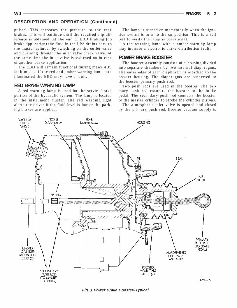
Fig. 1 Power Brake B
The lamp is turned on momentarily when the igni-tion switch is turn to the on position. This is a selftest to verify the lamp is operational.
A red warning lamp with a amber warning lampmay indicate a electronic brake distribution fault.
POWER BRAKE BOOSTERThe booster assembly consists of a housing divided
into separate chambers by two internal diaphragms.The outer edge of each diaphragm is attached to thebooster housing. The diaphragms are connected tothe booster primary push rod.
Two push rods are used in the booster. The pri-mary push rod connects the booster to the brakepedal. The secondary push rod connects the boosterto the master cylinder to stroke the cylinder pistons.
The atmospheric inlet valve is opened and closedby the primary push rod. Booster vacuum supply is
ooster–Typical
taoi
daafth
pmps
rtse
b
M
abbirret
F
ft
esma
tsbttsd
ta
5 - 4 BRAKES WJ
DESCRIPTION AND OPERATION (Continued)
hrough a hose attached to an intake manifold fittingt one end and to the booster check valve at thether. The vacuum check valve in the booster housings a one-way device that prevents vacuum leak back.
Power assist is generated by utilizing the pressureifferential between normal atmospheric pressurend a vacuum. The vacuum needed for booster oper-tion is taken directly from the engine intake mani-old. The entry point for atmospheric pressure ishrough a filter and inlet valve at the rear of theousing (Fig. 1).The chamber areas forward of the booster dia-
hragms are exposed to vacuum from the intakeanifold. The chamber areas to the rear of the dia-
hragms, are exposed to normal atmospheric pres-ure of 101.3 kilopascals (14.7 pounds/square in.).Brake pedal application causes the primary push
od to open the atmospheric inlet valve. This exposeshe area behind the diaphragms to atmospheric pres-ure. The resulting pressure differential provides thextra apply force for power assist.The booster check valve, check valve grommet and
ooster seals are serviceable.
ASTER CYLINDERThe master cylinder body is made of aluminum
nd contains a primary and secondary piston assem-ly. The cylinder body including the piston assem-lies are not serviceable. If diagnosis indicates annternal problem with the cylinder body, it must beeplaced as an assembly. The master cylinder has aemovable reservoir and fluid level indicator. The res-rvoir, reservoir grommets and fluid level switch arehe only replaceable parts on the master cylinder.
RONT DISC BRAKESThe calipers are twin piston type. The calipers are
ree to slide laterally on the anchor, this allows con-inuous compensation for lining wear.
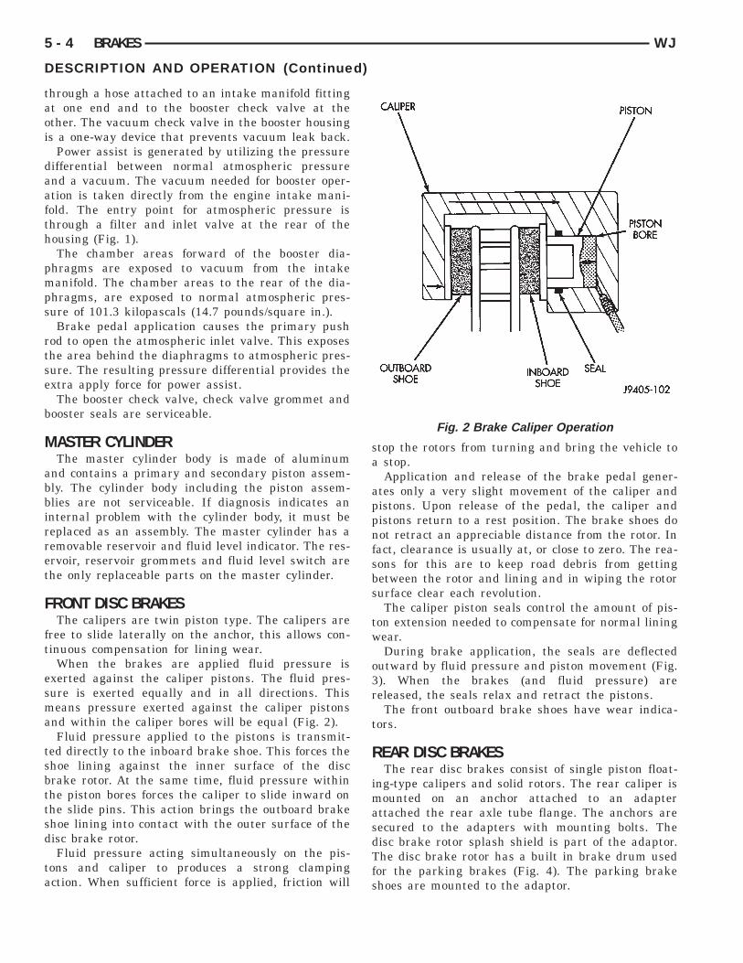
When the brakes are applied fluid pressure isxerted against the caliper pistons. The fluid pres-ure is exerted equally and in all directions. Thiseans pressure exerted against the caliper pistons
nd within the caliper bores will be equal (Fig. 2).Fluid pressure applied to the pistons is transmit-
ed directly to the inboard brake shoe. This forces thehoe lining against the inner surface of the discrake rotor. At the same time, fluid pressure withinhe piston bores forces the caliper to slide inward onhe slide pins. This action brings the outboard brakehoe lining into contact with the outer surface of theisc brake rotor.Fluid pressure acting simultaneously on the pis-
ons and caliper to produces a strong clampingction. When sufficient force is applied, friction will
stop the rotors from turning and bring the vehicle toa stop.
Application and release of the brake pedal gener-ates only a very slight movement of the caliper andpistons. Upon release of the pedal, the caliper andpistons return to a rest position. The brake shoes donot retract an appreciable distance from the rotor. Infact, clearance is usually at, or close to zero. The rea-sons for this are to keep road debris from gettingbetween the rotor and lining and in wiping the rotorsurface clear each revolution.
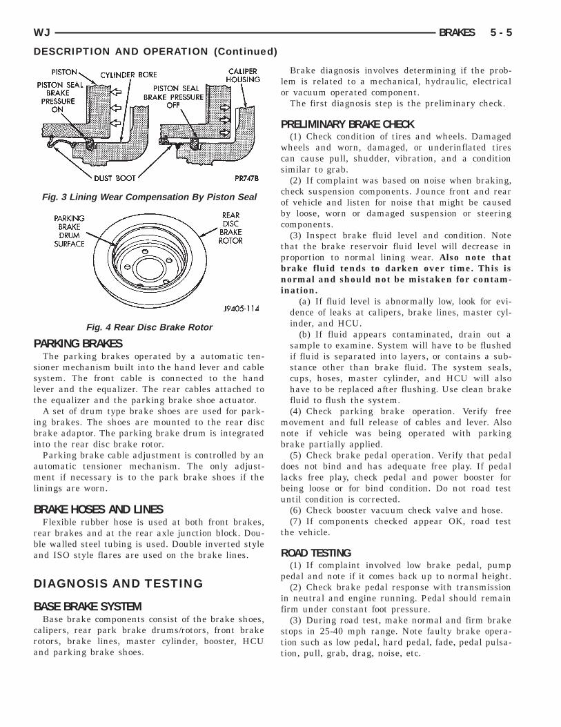
The caliper piston seals control the amount of pis-ton extension needed to compensate for normal liningwear.
During brake application, the seals are deflectedoutward by fluid pressure and piston movement (Fig.3). When the brakes (and fluid pressure) arereleased, the seals relax and retract the pistons.
The front outboard brake shoes have wear indica-tors.
REAR DISC BRAKESThe rear disc brakes consist of single piston float-
ing-type calipers and solid rotors. The rear caliper ismounted on an anchor attached to an adapterattached the rear axle tube flange. The anchors aresecured to the adapters with mounting bolts. Thedisc brake rotor splash shield is part of the adaptor.The disc brake rotor has a built in brake drum usedfor the parking brakes (Fig. 4). The parking brakeshoes are mounted to the adaptor.
Fig. 2 Brake Caliper Operation
P
sslt
ibi
aml
B
rba
D
B
cra
WJ BRAKES 5 - 5
DESCRIPTION AND OPERATION (Continued)
ARKING BRAKESThe parking brakes operated by a automatic ten-
ioner mechanism built into the hand lever and cableystem. The front cable is connected to the handever and the equalizer. The rear cables attached tohe equalizer and the parking brake shoe actuator.
A set of drum type brake shoes are used for park-ng brakes. The shoes are mounted to the rear discrake adaptor. The parking brake drum is integratednto the rear disc brake rotor.
Parking brake cable adjustment is controlled by anutomatic tensioner mechanism. The only adjust-ent if necessary is to the park brake shoes if the
inings are worn.
RAKE HOSES AND LINESFlexible rubber hose is used at both front brakes,
ear brakes and at the rear axle junction block. Dou-le walled steel tubing is used. Double inverted stylend ISO style flares are used on the brake lines.
IAGNOSIS AND TESTING
ASE BRAKE SYSTEMBase brake components consist of the brake shoes,
alipers, rear park brake drums/rotors, front brakeotors, brake lines, master cylinder, booster, HCUnd parking brake shoes.
Fig. 3 Lining Wear Compensation By Piston Seal
Fig. 4 Rear Disc Brake Rotor
Brake diagnosis involves determining if the prob-lem is related to a mechanical, hydraulic, electricalor vacuum operated component.
The first diagnosis step is the preliminary check.
PRELIMINARY BRAKE CHECK(1) Check condition of tires and wheels. Damaged
wheels and worn, damaged, or underinflated tirescan cause pull, shudder, vibration, and a conditionsimilar to grab.
(2) If complaint was based on noise when braking,check suspension components. Jounce front and rearof vehicle and listen for noise that might be causedby loose, worn or damaged suspension or steeringcomponents.
(3) Inspect brake fluid level and condition. Notethat the brake reservoir fluid level will decrease inproportion to normal lining wear. Also note thatbrake fluid tends to darken over time. This isnormal and should not be mistaken for contam-ination.
(a) If fluid level is abnormally low, look for evi-dence of leaks at calipers, brake lines, master cyl-inder, and HCU.
(b) If fluid appears contaminated, drain out asample to examine. System will have to be flushedif fluid is separated into layers, or contains a sub-stance other than brake fluid. The system seals,cups, hoses, master cylinder, and HCU will alsohave to be replaced after flushing. Use clean brakefluid to flush the system.(4) Check parking brake operation. Verify free
movement and full release of cables and lever. Alsonote if vehicle was being operated with parkingbrake partially applied.
(5) Check brake pedal operation. Verify that pedaldoes not bind and has adequate free play. If pedallacks free play, check pedal and power booster forbeing loose or for bind condition. Do not road testuntil condition is corrected.
(6) Check booster vacuum check valve and hose.(7) If components checked appear OK, road test
the vehicle.
ROAD TESTING(1) If complaint involved low brake pedal, pump
pedal and note if it comes back up to normal height.(2) Check brake pedal response with transmission
in neutral and engine running. Pedal should remainfirm under constant foot pressure.
(3) During road test, make normal and firm brakestops in 25-40 mph range. Note faulty brake opera-tion such as low pedal, hard pedal, fade, pedal pulsa-tion, pull, grab, drag, noise, etc.
bd
P
plco
da
t
L
elnaa
S
sabb
H
lbvh
P
l
rap
NA
B
cw
Dl
5 - 6 BRAKES WJ
DIAGNOSIS AND TESTING (Continued)
(4) Attempt to stop the vehicle with the parkingrake only (do not exceed 25 mph) and note grab,rag, noise, etc.
EDAL FALLS AWAYA brake pedal that falls away under steady foot
ressure is generally the result of a system leak. Theeak point could be at a brake line, fitting, hose, oraliper. If leakage is severe, fluid will be evident atr around the leaking component.Internal leakage (seal by-pass) in the master cylin-
er caused by worn or damaged piston cups, maylso be the problem cause.An internal leak in the ABS system may also be
he problem with no visual fluid leak.
OW PEDALIf a low pedal is experienced, pump the pedal sev-
ral times. If the pedal comes back up, the mostikely causes are worn linings, rotors, or calipers areot sliding on the slide pins. The proper course ofction is to inspect and replace all worn componentnd make the proper adjustments.
PONGY PEDALA spongy pedal is most often caused by air in the
ystem. However substandard brake hoses can causespongy pedal. The proper course of action is to
leed the system, and replace substandard qualityrake hoses if suspected.
ARD PEDAL OR HIGH PEDAL EFFORTA hard pedal or high pedal effort may be due to
ining that is water soaked, contaminated, glazed, oradly worn. The power booster, check valve, checkalve seal/grommet or low vacuum could also cause aard pedal or high pedal effort.
EDAL PULSATIONPedal pulsation is caused by components that are
oose, or beyond tolerance limits.The primary cause of pulsation are disc brake
otors with excessive lateral runout or thickness vari-tion. Other causes are loose wheel bearings or cali-ers and worn, damaged tires.
OTE: Some pedal pulsation may be felt duringBS activation.
RAKE DRAGBrake drag occurs when the lining is in constant
ontact with the rotor or drum. Drag can occur at oneheel, all wheels, fronts only, or rears only.Drag is a product of incomplete brake release.rag can be minor or severe enough to overheat the
inings, rotors and park brake drums.
Minor drag will usually cause slight surface char-ring of the lining. It can also generate hard spots inrotors and park brake drums from the overheat-cooldown process. In most cases, the rotors, wheels andtires are quite warm to the touch after the vehicle isstopped.
Severe drag can char the brake lining all the waythrough. It can also distort and score rotors to thepoint of replacement. The wheels, tires and brakecomponents will be extremely hot. In severe cases,the lining may generate smoke as it chars from over-heating.
Common causes of brake drag are:• Parking brake partially applied.• Loose/worn wheel bearing.• Seized caliper.• Caliper binding.• Loose caliper mounting.• Mis-assembled components.• Damaged brake lines.If brake drag occurs at the front, rear or all
wheels, the problem may be related to a blocked mas-ter cylinder return port, faulty power booster (binds-does not release) or the ABS system.
BRAKE FADEBrake fade is usually a product of overheating
caused by brake drag. However, brake overheatingand resulting fade can also be caused by riding thebrake pedal, making repeated high deceleration stopsin a short time span, or constant braking on steepmountain roads. Refer to the Brake Drag informationin this section for causes.
BRAKE PULLFront brake pull condition could result from:• Contaminated lining in one caliper• Seized caliper piston• Binding caliper• Loose caliper• Rusty caliper slide surfaces• Improper brake shoes• Damaged rotor• Wheel alignment.• Tire pressure.A worn, damaged wheel bearing or suspension
component are further causes of pull. A damagedfront tire (bruised, ply separation) can also causepull.
A common and frequently misdiagnosed pull condi-tion is where direction of pull changes after a fewstops. The cause is a combination of brake drag fol-lowed by fade at one of the brake units.
As the dragging brake overheats, efficiency is soreduced that fade occurs. Since the opposite brakeunit is still functioning normally, its braking effect is
mf
ptdn
R
acilHm
BW
ldmdb
B
lwwil
W
m
p
Ns
prtTt
B
dpts
WJ BRAKES 5 - 7
DIAGNOSIS AND TESTING (Continued)
agnified. This causes pull to switch direction inavor of the normally functioning brake unit.
An additional point when diagnosing a change inull condition concerns brake cool down. Rememberhat pull will return to the original direction, if theragging brake unit is allowed to cool down (and isot seriously damaged).
EAR BRAKE DRAG OR PULLRear drag or pull may be caused by improperly
djusted park brake shoes or seized parking brakeables, contaminated lining, bent or binding shoes ormproperly assembled components. This is particu-arly true when only one rear wheel is involved.owever, when both rear wheels are affected, theaster cylinder or ABS system could be at fault.
RAKES DO NOT HOLD AFTER DRIVING THROUGH DEEPATER PUDDLESThis condition is generally caused by water soaked
ining. If the lining is only wet, it can be dried byriving with the brakes very lightly applied for aile or two. However, if the lining is both soaked and
irt contaminated, cleaning and or replacement wille necessary.
RAKE LINING CONTAMINATIONBrake lining contamination is mostly a product of
eaking calipers or worn seals, driving through deepater puddles, or lining that has become coveredith grease and grit during repair. Contaminated lin-
ng should be replaced to avoid further brake prob-ems.
HEEL AND TIRE PROBLEMSSome conditions attributed to brake componentsay actually be caused by a wheel or tire problem.A damaged wheel can cause shudder, vibration and
ull. A worn or damaged tire can also cause pull.
OTE: Propshaft angle can also cause vibration/hudder.
Severely worn tires with very little tread left canroduce a grab-like condition as the tire loses andecovers traction. Flat-spotted tires can cause vibra-ion and generate shudder during brake operation.ire damage such as a severe bruise, cut, ply separa-ion, low air pressure can cause pull and vibration.
RAKE NOISESSome brake noise is common on some disc brakes
uring the first few stops after a vehicle has beenarked overnight or stored. This is primarily due tohe formation of trace corrosion (light rust) on metalurfaces. This light corrosion is typically cleared from
the metal surfaces after a few brake applicationscausing the noise to subside.
BRAKE SQUEAK/SQUEALBrake squeak or squeal may be due to linings that
are wet or contaminated with brake fluid, grease, oroil. Glazed linings and rotors with hard spots canalso contribute to squeak. Dirt and foreign materialembedded in the brake lining will also cause squeak/squeal.
A very loud squeak or squeal is frequently a sign ofseverely worn brake lining. If the lining has wornthrough to the brake shoes in spots, metal-to-metalcontact occurs. If the condition is allowed to continue,rotors may become so scored that replacement is nec-essary.
NOTE: The front outer brake shoes are equippedwith a wear indicator. The indicator will produce anaudible noise when it contacts the rotor surface.
BRAKE CHATTERBrake chatter is usually caused by loose or worn
components, or glazed/burnt lining. Rotors with hardspots can also contribute to chatter. Additional causesof chatter are out-of-tolerance rotors, brake lining notsecurely attached to the shoes, loose wheel bearingsand contaminated brake lining.
THUMP/CLUNK NOISEThumping or clunk noises during braking are fre-
quently not caused by brake components. In manycases, such noises are caused by loose or damagedsteering, suspension, or engine components.
BRAKE LAMP SWITCHBrake lamp switch operation can be tested with an
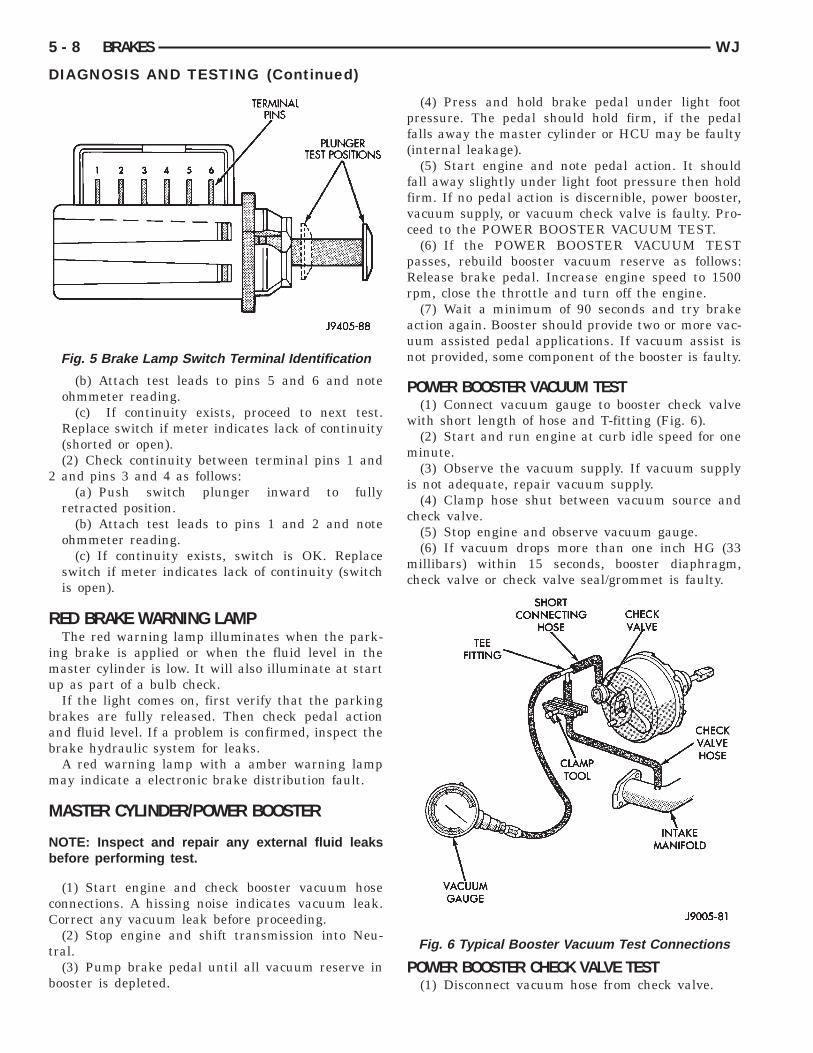
ohmmeter. The ohmmeter is used to check continuitybetween the pin terminals at different plunger posi-tions (Fig. 5).
NOTE: The switch wire harness must be discon-nected before testing switch continuity.
SWITCH CIRCUIT IDENTIFICATION• Terminals 1 and 2 are for brake sensor circuit.• Terminals 5 and 6 are for the stop lamp circuit.• Terminals 3 and 4 are for the speed control cir-
cuit.
SWITCH CONTINUITY TEST(1) Check continuity between terminal pins 5 and
6 as follows:(a) Pull plunger all the way out to fully extended
position.
2
R
imu
bab
m
M
Nb
cC
t
b
5 - 8 BRAKES WJ
DIAGNOSIS AND TESTING (Continued)
(b) Attach test leads to pins 5 and 6 and noteohmmeter reading.
(c) If continuity exists, proceed to next test.Replace switch if meter indicates lack of continuity(shorted or open).(2) Check continuity between terminal pins 1 andand pins 3 and 4 as follows:
(a) Push switch plunger inward to fullyretracted position.
(b) Attach test leads to pins 1 and 2 and noteohmmeter reading.
(c) If continuity exists, switch is OK. Replaceswitch if meter indicates lack of continuity (switchis open).
ED BRAKE WARNING LAMPThe red warning lamp illuminates when the park-
ng brake is applied or when the fluid level in theaster cylinder is low. It will also illuminate at startp as part of a bulb check.If the light comes on, first verify that the parking
rakes are fully released. Then check pedal actionnd fluid level. If a problem is confirmed, inspect therake hydraulic system for leaks.A red warning lamp with a amber warning lampay indicate a electronic brake distribution fault.
ASTER CYLINDER/POWER BOOSTER
OTE: Inspect and repair any external fluid leaksefore performing test.
(1) Start engine and check booster vacuum hoseonnections. A hissing noise indicates vacuum leak.orrect any vacuum leak before proceeding.(2) Stop engine and shift transmission into Neu-
ral.(3) Pump brake pedal until all vacuum reserve in
ooster is depleted.
Fig. 5 Brake Lamp Switch Terminal Identification
(4) Press and hold brake pedal under light footpressure. The pedal should hold firm, if the pedalfalls away the master cylinder or HCU may be faulty(internal leakage).
(5) Start engine and note pedal action. It shouldfall away slightly under light foot pressure then holdfirm. If no pedal action is discernible, power booster,vacuum supply, or vacuum check valve is faulty. Pro-ceed to the POWER BOOSTER VACUUM TEST.
(6) If the POWER BOOSTER VACUUM TESTpasses, rebuild booster vacuum reserve as follows:Release brake pedal. Increase engine speed to 1500rpm, close the throttle and turn off the engine.
(7) Wait a minimum of 90 seconds and try brakeaction again. Booster should provide two or more vac-uum assisted pedal applications. If vacuum assist isnot provided, some component of the booster is faulty.
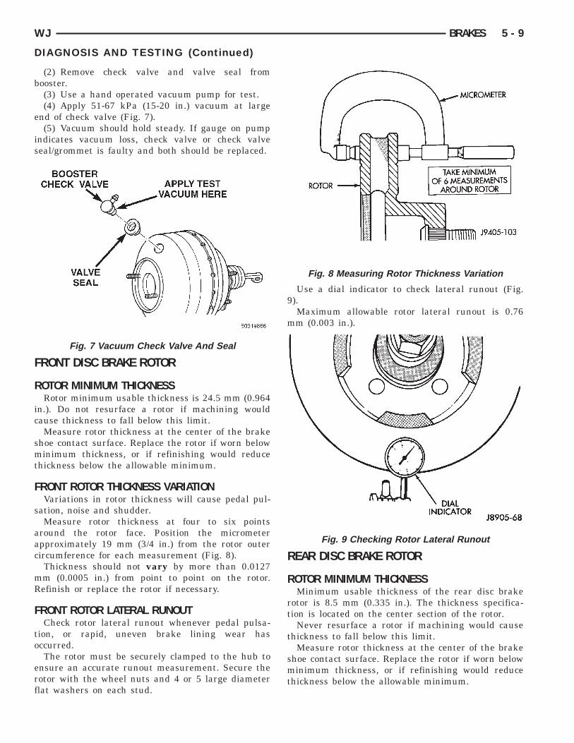
POWER BOOSTER VACUUM TEST(1) Connect vacuum gauge to booster check valve
with short length of hose and T-fitting (Fig. 6).(2) Start and run engine at curb idle speed for one
minute.(3) Observe the vacuum supply. If vacuum supply
is not adequate, repair vacuum supply.(4) Clamp hose shut between vacuum source and
check valve.(5) Stop engine and observe vacuum gauge.(6) If vacuum drops more than one inch HG (33
millibars) within 15 seconds, booster diaphragm,check valve or check valve seal/grommet is faulty.
POWER BOOSTER CHECK VALVE TEST(1) Disconnect vacuum hose from check valve.
Fig. 6 Typical Booster Vacuum Test Connections
b
e
is
F
R
ic
smt
F
s
aac
mR
F
to
erf
WJ BRAKES 5 - 9
DIAGNOSIS AND TESTING (Continued)
(2) Remove check valve and valve seal fromooster.(3) Use a hand operated vacuum pump for test.(4) Apply 51-67 kPa (15-20 in.) vacuum at large
nd of check valve (Fig. 7).(5) Vacuum should hold steady. If gauge on pump
ndicates vacuum loss, check valve or check valveeal/grommet is faulty and both should be replaced.
RONT DISC BRAKE ROTOR
OTOR MINIMUM THICKNESSRotor minimum usable thickness is 24.5 mm (0.964
n.). Do not resurface a rotor if machining wouldause thickness to fall below this limit.Measure rotor thickness at the center of the brake
hoe contact surface. Replace the rotor if worn belowinimum thickness, or if refinishing would reduce
hickness below the allowable minimum.
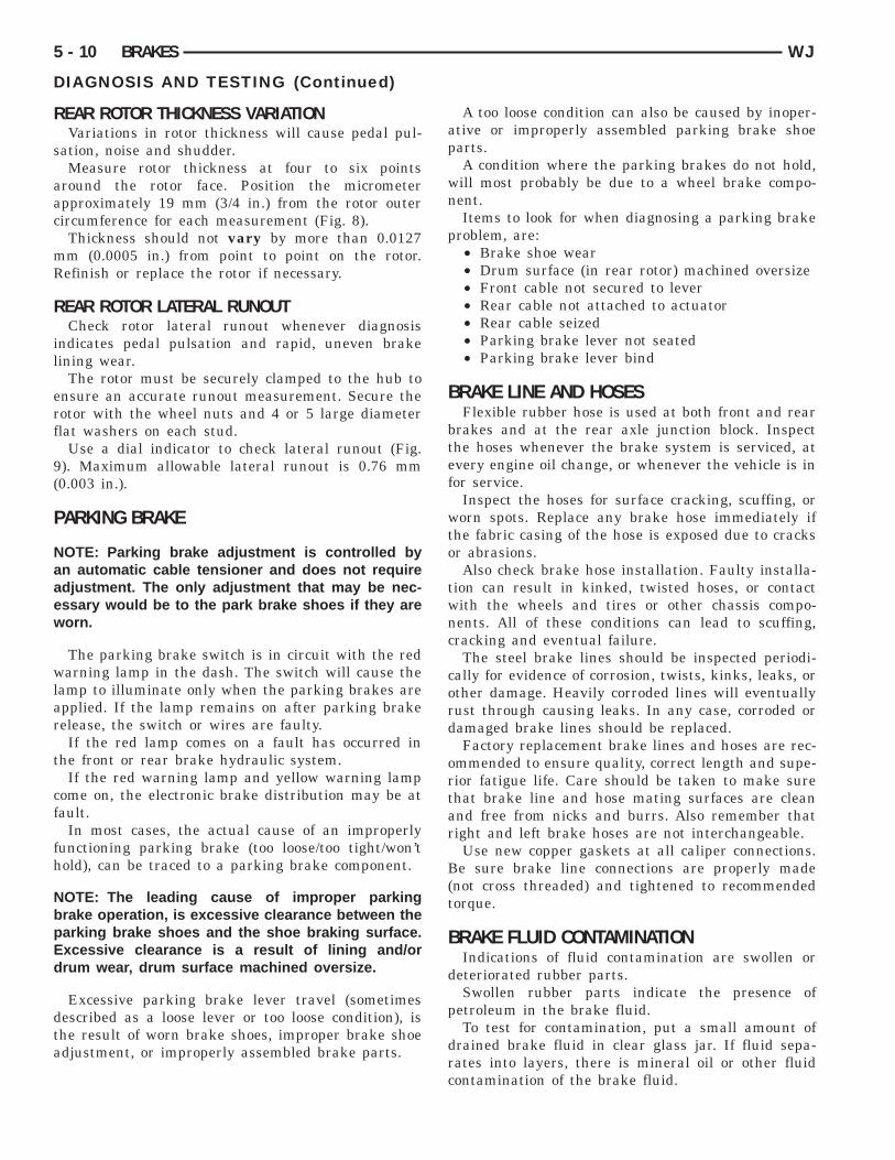
RONT ROTOR THICKNESS VARIATIONVariations in rotor thickness will cause pedal pul-
ation, noise and shudder.Measure rotor thickness at four to six points
round the rotor face. Position the micrometerpproximately 19 mm (3/4 in.) from the rotor outerircumference for each measurement (Fig. 8).Thickness should not vary by more than 0.0127m (0.0005 in.) from point to point on the rotor.efinish or replace the rotor if necessary.
RONT ROTOR LATERAL RUNOUTCheck rotor lateral runout whenever pedal pulsa-
ion, or rapid, uneven brake lining wear hasccurred.The rotor must be securely clamped to the hub to
nsure an accurate runout measurement. Secure theotor with the wheel nuts and 4 or 5 large diameterlat washers on each stud.
Fig. 7 Vacuum Check Valve And Seal
Use a dial indicator to check lateral runout (Fig.9).
Maximum allowable rotor lateral runout is 0.76mm (0.003 in.).
REAR DISC BRAKE ROTOR
ROTOR MINIMUM THICKNESSMinimum usable thickness of the rear disc brake
rotor is 8.5 mm (0.335 in.). The thickness specifica-tion is located on the center section of the rotor.
Never resurface a rotor if machining would causethickness to fall below this limit.
Measure rotor thickness at the center of the brakeshoe contact surface. Replace the rotor if worn belowminimum thickness, or if refinishing would reducethickness below the allowable minimum.
Fig. 8 Measuring Rotor Thickness Variation
Fig. 9 Checking Rotor Lateral Runout
R
s
aac
mR
R
il
erf
9(
P
Naaew
wlar
t
cf
fh
NbpEd
dta
5 - 10 BRAKES WJ
DIAGNOSIS AND TESTING (Continued)
EAR ROTOR THICKNESS VARIATIONVariations in rotor thickness will cause pedal pul-
ation, noise and shudder.Measure rotor thickness at four to six points
round the rotor face. Position the micrometerpproximately 19 mm (3/4 in.) from the rotor outerircumference for each measurement (Fig. 8).Thickness should not vary by more than 0.0127m (0.0005 in.) from point to point on the rotor.efinish or replace the rotor if necessary.
EAR ROTOR LATERAL RUNOUTCheck rotor lateral runout whenever diagnosis
ndicates pedal pulsation and rapid, uneven brakeining wear.
The rotor must be securely clamped to the hub tonsure an accurate runout measurement. Secure theotor with the wheel nuts and 4 or 5 large diameterlat washers on each stud.
Use a dial indicator to check lateral runout (Fig.). Maximum allowable lateral runout is 0.76 mm0.003 in.).
ARKING BRAKE
OTE: Parking brake adjustment is controlled byn automatic cable tensioner and does not requiredjustment. The only adjustment that may be nec-ssary would be to the park brake shoes if they areorn.
The parking brake switch is in circuit with the redarning lamp in the dash. The switch will cause the
amp to illuminate only when the parking brakes arepplied. If the lamp remains on after parking brakeelease, the switch or wires are faulty.If the red lamp comes on a fault has occurred in
he front or rear brake hydraulic system.If the red warning lamp and yellow warning lamp
ome on, the electronic brake distribution may be atault.
In most cases, the actual cause of an improperlyunctioning parking brake (too loose/too tight/won’told), can be traced to a parking brake component.
OTE: The leading cause of improper parkingrake operation, is excessive clearance between thearking brake shoes and the shoe braking surface.xcessive clearance is a result of lining and/orrum wear, drum surface machined oversize.
Excessive parking brake lever travel (sometimesescribed as a loose lever or too loose condition), ishe result of worn brake shoes, improper brake shoedjustment, or improperly assembled brake parts.
A too loose condition can also be caused by inoper-ative or improperly assembled parking brake shoeparts.
A condition where the parking brakes do not hold,will most probably be due to a wheel brake compo-nent.
Items to look for when diagnosing a parking brakeproblem, are:
• Brake shoe wear• Drum surface (in rear rotor) machined oversize• Front cable not secured to lever• Rear cable not attached to actuator• Rear cable seized• Parking brake lever not seated• Parking brake lever bind
BRAKE LINE AND HOSESFlexible rubber hose is used at both front and rear
brakes and at the rear axle junction block. Inspectthe hoses whenever the brake system is serviced, atevery engine oil change, or whenever the vehicle is infor service.
Inspect the hoses for surface cracking, scuffing, orworn spots. Replace any brake hose immediately ifthe fabric casing of the hose is exposed due to cracksor abrasions.
Also check brake hose installation. Faulty installa-tion can result in kinked, twisted hoses, or contactwith the wheels and tires or other chassis compo-nents. All of these conditions can lead to scuffing,cracking and eventual failure.
The steel brake lines should be inspected periodi-cally for evidence of corrosion, twists, kinks, leaks, orother damage. Heavily corroded lines will eventuallyrust through causing leaks. In any case, corroded ordamaged brake lines should be replaced.
Factory replacement brake lines and hoses are rec-ommended to ensure quality, correct length and supe-rior fatigue life. Care should be taken to make surethat brake line and hose mating surfaces are cleanand free from nicks and burrs. Also remember thatright and left brake hoses are not interchangeable.
Use new copper gaskets at all caliper connections.Be sure brake line connections are properly made(not cross threaded) and tightened to recommendedtorque.
BRAKE FLUID CONTAMINATIONIndications of fluid contamination are swollen or
deteriorated rubber parts.Swollen rubber parts indicate the presence of
petroleum in the brake fluid.To test for contamination, put a small amount of
drained brake fluid in clear glass jar. If fluid sepa-rates into layers, there is mineral oil or other fluidcontamination of the brake fluid.

orh
S
B
bif
s
M
lbB
B
Tr
Tsa
B
foa
WJ BRAKES 5 - 11
DIAGNOSIS AND TESTING (Continued)
If brake fluid is contaminated, drain and thor-ughly flush system. Replace master cylinder witheservoir, caliper seals, HCU and all hydraulic fluidoses.
ERVICE PROCEDURES
RAKE FLUID LEVELAlways clean the master cylinder reservoir and cap
efore adding fluid. This will prevent dirt from fall-ng in the reservoir and contaminating the brakeluid.
The reservoir has a MIN and a MAX mark on theide (Fig. 10) fill to the MAX mark.
ASTER CYLINDER BLEEDINGA new master cylinder should be bled before instal-
ation on the vehicle. Required bleeding tools includeleed tubes and a wood dowel to stroke the pistons.leed tubes can be fabricated from brake line.
LEEDING PROCEDURE(1) Mount master cylinder in vise with brass jaws.(2) Attach bleed tubes to cylinder outlet ports.
hen position each tube end into the bottom of theeservoir (Fig. 11).(3) Fill reservoir with fresh brake fluid.(4) Press cylinder pistons inward with wood dowel.
hen release pistons and allow them to return underpring pressure. Continue bleeding operations untilir bubbles are no longer visible in fluid.
ASE BRAKE BLEEDINGUse Mopar brake fluid, or an equivalent quality
luid meeting SAE J1703-F and DOT 3 standardsnly. Use fresh, clean fluid from a sealed container atll times.
Fig. 10 Master Cylinder Fluid Level
Do not pump the brake pedal at any time whilebleeding. Air in the system will be compressed intosmall bubbles that are distributed throughout thehydraulic system. This will make additional bleedingoperations necessary.
Do not allow the master cylinder to run out of fluidduring bleed operations. An empty cylinder will allowadditional air to be drawn into the system. Check thecylinder fluid level frequently and add fluid asneeded.
Bleed only one brake component at a time in thefollowing sequence:
• Master Cylinder• Right Rear Wheel• Left Rear Wheel• Right Front Wheel• Left Front Wheel
MANUAL BLEEDING(1) Fill the master cylinder reservoir with brake
fluid.(2) If calipers are overhauled, open all caliper
bleed screws. Then close each bleed screw as fluidstarts to drip from it. Top off master cylinder reser-voir once more before proceeding.
(3) Attach one end of bleed hose to bleed screwand insert opposite end in glass container partiallyfilled with brake fluid (Fig. 12). Be sure end of bleedhose is immersed in fluid.
(4) Open up bleeder, then have a helper pressdown the brake pedal. Once the pedal is down closethe bleeder. Repeat bleeding until fluid stream isclear and free of bubbles. Then move to the nextwheel.
PRESSURE BLEEDINGFollow the manufacturers instructions carefully
when using pressure equipment. Do not exceed thetank manufacturers pressure recommendations. Gen-
Fig. 11 Master Cylinder Bleeding
ef
p
iaa6
D
wsmlamo
Ctm
B
ptr
oaf
5 - 12 BRAKES WJ
SERVICE PROCEDURES (Continued)
rally, a tank pressure of 51-67 kPa (15-20 psi) is suf-icient for bleeding.
Fill the bleeder tank with recommended fluid andurge air from the tank lines before bleeding.Do not pressure bleed without a proper master cyl-
nder adapter. The wrong adapter can lead to leak-ge, or drawing air back into the system. Usedapter provided with the equipment or Adapter921.
ISC ROTOR MACHININGThe disc brake rotor can be machined if scored ororn. The lathe must machine both sides of the rotor
imultaneously with dual cutter heads. The rotorounting surface must be clean before placing on the
athe. Equipment capable of machining only one sidet a time may produce a tapered rotor. A hubounted on-vehicle lathe is recommended. This type
f lathe trues the rotor to the vehicles hub/bearing.
AUTION: Brake rotors that do not meet minimumhickness specifications before or after machiningust be replaced.
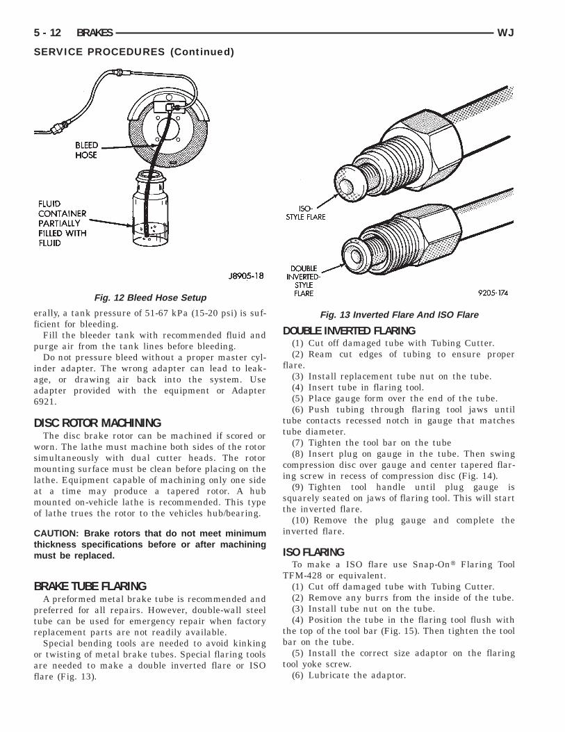
RAKE TUBE FLARINGA preformed metal brake tube is recommended and
referred for all repairs. However, double-wall steelube can be used for emergency repair when factoryeplacement parts are not readily available.Special bending tools are needed to avoid kinking
r twisting of metal brake tubes. Special flaring toolsre needed to make a double inverted flare or ISOlare (Fig. 13).
Fig. 12 Bleed Hose Setup
DOUBLE INVERTED FLARING(1) Cut off damaged tube with Tubing Cutter.(2) Ream cut edges of tubing to ensure proper
flare.(3) Install replacement tube nut on the tube.(4) Insert tube in flaring tool.(5) Place gauge form over the end of the tube.(6) Push tubing through flaring tool jaws until
tube contacts recessed notch in gauge that matchestube diameter.
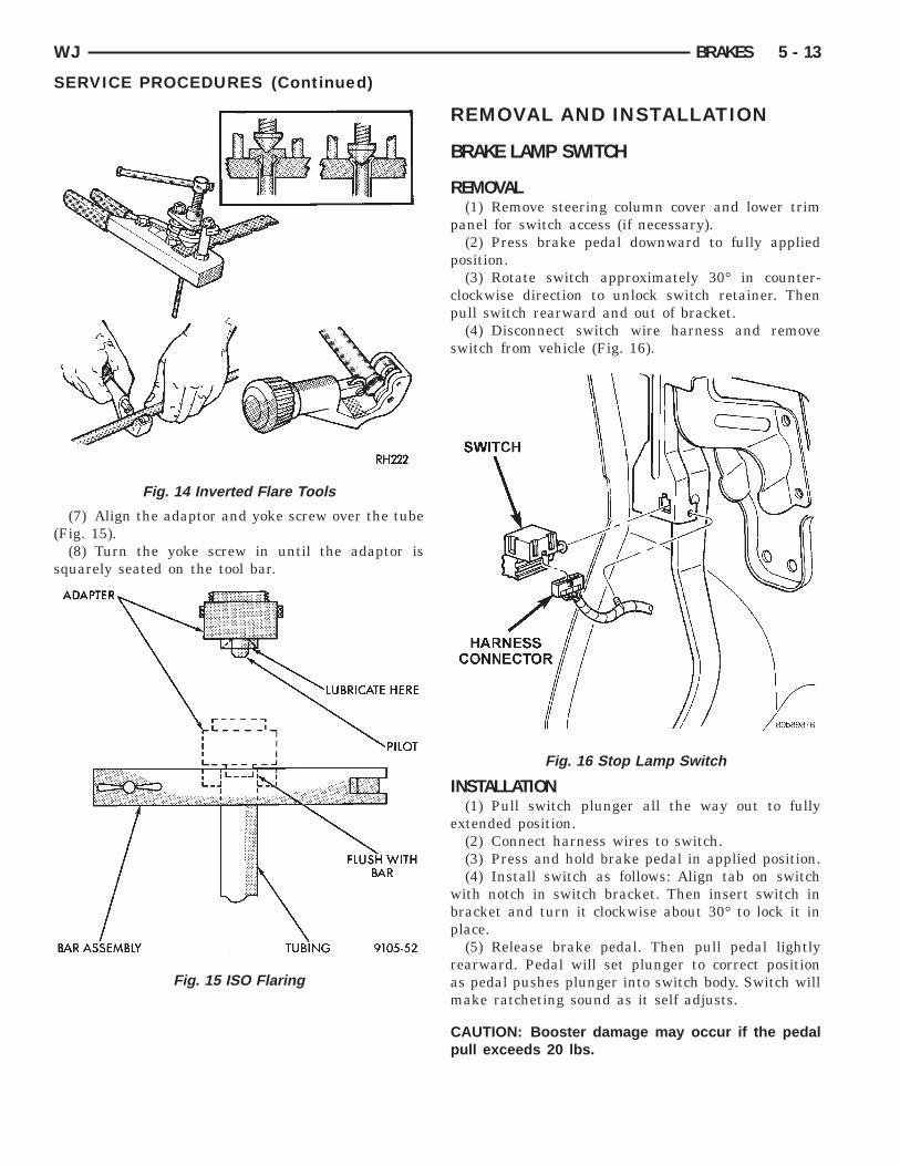
(7) Tighten the tool bar on the tube(8) Insert plug on gauge in the tube. Then swing
compression disc over gauge and center tapered flar-ing screw in recess of compression disc (Fig. 14).
(9) Tighten tool handle until plug gauge issquarely seated on jaws of flaring tool. This will startthe inverted flare.
(10) Remove the plug gauge and complete theinverted flare.
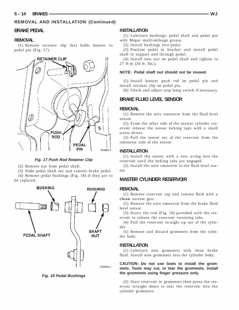
ISO FLARINGTo make a ISO flare use Snap-Ont Flaring Tool
TFM-428 or equivalent.(1) Cut off damaged tube with Tubing Cutter.(2) Remove any burrs from the inside of the tube.(3) Install tube nut on the tube.(4) Position the tube in the flaring tool flush with
the top of the tool bar (Fig. 15). Then tighten the toolbar on the tube.
(5) Install the correct size adaptor on the flaringtool yoke screw.
(6) Lubricate the adaptor.
Fig. 13 Inverted Flare And ISO Flare
(
s
WJ BRAKES 5 - 13
SERVICE PROCEDURES (Continued)
(7) Align the adaptor and yoke screw over the tubeFig. 15).
(8) Turn the yoke screw in until the adaptor isquarely seated on the tool bar.
Fig. 14 Inverted Flare Tools
Fig. 15 ISO Flaring
REMOVAL AND INSTALLATION
BRAKE LAMP SWITCH
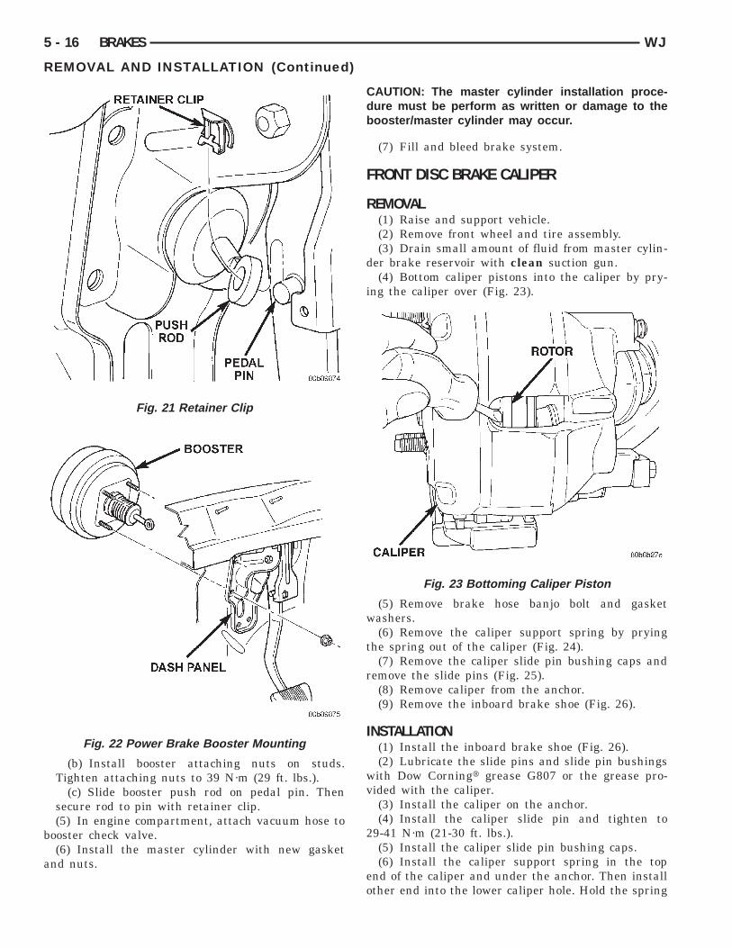
REMOVAL(1) Remove steering column cover and lower trim
panel for switch access (if necessary).(2) Press brake pedal downward to fully applied
position.(3) Rotate switch approximately 30° in counter-
clockwise direction to unlock switch retainer. Thenpull switch rearward and out of bracket.
(4) Disconnect switch wire harness and removeswitch from vehicle (Fig. 16).
INSTALLATION(1) Pull switch plunger all the way out to fully
extended position.(2) Connect harness wires to switch.(3) Press and hold brake pedal in applied position.(4) Install switch as follows: Align tab on switch
with notch in switch bracket. Then insert switch inbracket and turn it clockwise about 30° to lock it inplace.
(5) Release brake pedal. Then pull pedal lightlyrearward. Pedal will set plunger to correct positionas pedal pushes plunger into switch body. Switch willmake ratcheting sound as it self adjusts.
CAUTION: Booster damage may occur if the pedalpull exceeds 20 lbs.
Fig. 16 Stop Lamp Switch
B
R
p
b
5 - 14 BRAKES WJ
REMOVAL AND INSTALLATION (Continued)
RAKE PEDAL
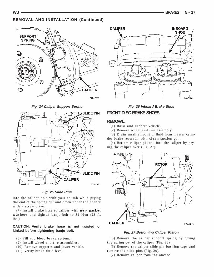
EMOVAL(1) Remove retainer clip that holds booster to
edal pin (Fig. 17).
(2) Remove nut from pedal shaft.(3) Slide pedal shaft out and remove brake pedal.(4) Remove pedal bushings (Fig. 18) if they are to
e replaced.
Fig. 17 Push Rod Retainer Clip
Fig. 18 Pedal Bushings
INSTALLATION(1) Lubricate bushings, pedal shaft and pedal pin
with Mopar multi-mileage grease.(2) Install bushings into pedal.(3) Position pedal in bracket and install pedal
shaft in support and through pedal.(4) Install new nut on pedal shaft and tighten to
27 N·m (20 ft. lbs.).
NOTE: Pedal shaft nut should not be reused.
(5) Install booster push rod on pedal pin andinstall retainer clip on pedal pin.
(6) Check and adjust stop lamp switch if necessary.
BRAKE FLUID LEVEL SENSOR
REMOVAL(1) Remove the wire connector from the fluid level
sensor.(2) From the other side of the master cylinder res-
ervoir release the sensor locking taps with a smallscrew driver.
(3) Pull the sensor out of the reservoir from theconnector side of the sensor.
INSTALLATION(1) Install the sensor with a new o-ring into the
reservoir until the locking tabs are engaged.(2) Install the wire connector to the fluid level sen-
sor.
MASTER CYLINDER RESERVOIR
REMOVAL(1) Remove reservoir cap and remove fluid with a
clean suction gun.(2) Remove the wire connector from the brake fluid
level sensor.(3) Insert the tool (Fig. 19) provided with the res-
ervoir to release the reservoir retaining tabs.(4) Pull the reservoir straight up out of the cylin-
der.(5) Remove and discard grommets from the cylin-
der body.
INSTALLATION(1) Lubricate new grommets with clean brake
fluid. Install new grommets into the cylinder body.
CAUTION: Do not use tools to install the grom-mets. Tools may cut, or tear the grommets. Installthe grommets using finger pressure only.
(2) Start reservoir in grommets then press the res-ervoir straight down to seat the reservoir into thecylinder grommets.

Cl
l
M
R
l
b
I
Ni
wa
Capo
t
WJ BRAKES 5 - 15
REMOVAL AND INSTALLATION (Continued)
AUTION: Do not rock the reservoir during instal-ation.
(3) Verify retaining tabs are seated.(4) Install the wire connector to the brake fluid
evel sensor.(5) Fill master cylinder.
ASTER CYLINDER
EMOVAL(1) Remove the wire connector from the brake fluid
evel sensor.(2) Remove brake lines from master cylinder.(3) Remove nuts that attach master cylinder to
ooster studs (Fig. 20).(4) Remove master cylinder from booster.
NSTALLATION
OTE: Bleed new master cylinder on bench beforenstallation, refer to Service Procedures.
(1) Have an assistant depress the brake pedalhile guiding the master cylinder on the booster rodnd mounting studs.
AUTION: Do not depress brake pedal too hardnd ensure the booster rod is in the master cylinderiston or booster/master cylinder damage willccur.
(2) Install master cylinder mounting nuts andighten nuts to 25 N·m (18 lb. lbs.).
Fig. 19 Release Tool
NOTE: Use original or factory replacement nutsonly.
(3) Install brake lines and tighten to 16 N·m (144in. lbs.).
(4) Install fluid level sensor connector.(5) Fill and bleed brake system.
POWER BRAKE BOOSTER
REMOVAL(1) Remove the master cylinder.(2) Disconnect vacuum hose at booster check valve.(3) Remove retainer clip (Fig. 21) that holds
booster push rod on pedal pin. Then slide push rodoff pin.
(4) Remove four nuts (Fig. 22) that attach boosterto dash panel.
(5) In engine compartment, slide booster forward,tilt it upward slightly, and remove it from enginecompartment.
INSTALLATION(1) Check condition of grommet that secures check
valve in booster. Replace grommet if cut, torn, orloose.
(2) Install new booster dash seal.(3) Align and position booster on engine compart-
ment side of dash panel.(4) Inside passenger compartment:
(a) Lubricate pedal pin Mopar multi-mileagegrease.
Fig. 20 Master Cylinder Mounting
b
a
i
w
t
r
v
2
eo
5 - 16 BRAKES WJ
REMOVAL AND INSTALLATION (Continued)
(b) Install booster attaching nuts on studs.Tighten attaching nuts to 39 N·m (29 ft. lbs.).
(c) Slide booster push rod on pedal pin. Thensecure rod to pin with retainer clip.(5) In engine compartment, attach vacuum hose to
ooster check valve.(6) Install the master cylinder with new gasket
nd nuts.
Fig. 21 Retainer Clip
Fig. 22 Power Brake Booster Mounting
CAUTION: The master cylinder installation proce-dure must be perform as written or damage to thebooster/master cylinder may occur.
(7) Fill and bleed brake system.
FRONT DISC BRAKE CALIPER
REMOVAL(1) Raise and support vehicle.(2) Remove front wheel and tire assembly.(3) Drain small amount of fluid from master cylin-
der brake reservoir with clean suction gun.(4) Bottom caliper pistons into the caliper by pry-
ng the caliper over (Fig. 23).
(5) Remove brake hose banjo bolt and gasketashers.(6) Remove the caliper support spring by prying
he spring out of the caliper (Fig. 24).(7) Remove the caliper slide pin bushing caps and
emove the slide pins (Fig. 25).(8) Remove caliper from the anchor.(9) Remove the inboard brake shoe (Fig. 26).
INSTALLATION(1) Install the inboard brake shoe (Fig. 26).(2) Lubricate the slide pins and slide pin bushings
with Dow Corningt grease G807 or the grease pro-ided with the caliper.(3) Install the caliper on the anchor.(4) Install the caliper slide pin and tighten to
9-41 N·m (21-30 ft. lbs.).(5) Install the caliper slide pin bushing caps.(6) Install the caliper support spring in the top
nd of the caliper and under the anchor. Then installther end into the lower caliper hole. Hold the spring
Fig. 23 Bottoming Caliper Piston
itw
wl
Ck
i
t
r
WJ BRAKES 5 - 17
REMOVAL AND INSTALLATION (Continued)
nto the caliper hole with your thumb while pryinghe end of the spring out and down under the anchorith a screw drive.(7) Install brake hose to caliper with new gasketashers and tighten banjo bolt to 31 N·m (23 ft.
bs.).
AUTION: Verify brake hose is not twisted orinked before tightening banjo bolt.
(8) Fill and bleed brake system.(9) Install wheel and tire assemblies.(10) Remove supports and lower vehicle.(11) Verify brake fluid level.
Fig. 24 Caliper Support Spring
Fig. 25 Slide Pins
FRONT DISC BRAKE SHOES
REMOVAL(1) Raise and support vehicle.(2) Remove wheel and tire assembly.(3) Drain small amount of fluid from master cylin-
der brake reservoir with clean suction gun.(4) Bottom caliper pistons into the caliper by pry-
ng the caliper over (Fig. 27).
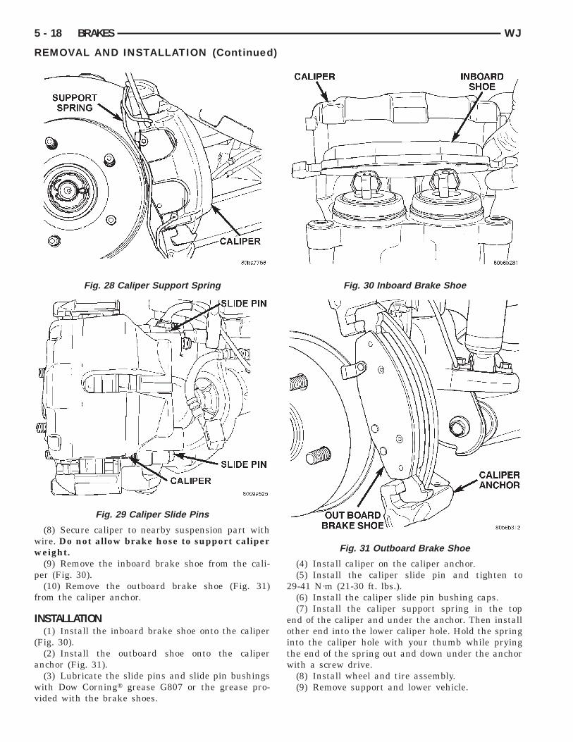
(5) Remove the caliper support spring by pryinghe spring out of the caliper (Fig. 28).
(6) Remove the caliper slide pin bushing caps andemove the slide pins (Fig. 29).(7) Remove caliper from the anchor.
Fig. 26 Inboard Brake Shoe
Fig. 27 Bottoming Caliper Piston
ww
p
f
I
(
a
wv
5 - 18 BRAKES WJ
REMOVAL AND INSTALLATION (Continued)
(8) Secure caliper to nearby suspension part withire. Do not allow brake hose to support calipereight.(9) Remove the inboard brake shoe from the cali-
er (Fig. 30).(10) Remove the outboard brake shoe (Fig. 31)
rom the caliper anchor.
NSTALLATION(1) Install the inboard brake shoe onto the caliper
Fig. 30).(2) Install the outboard shoe onto the caliper
nchor (Fig. 31).(3) Lubricate the slide pins and slide pin bushingsith Dow Corningt grease G807 or the grease pro-ided with the brake shoes.
Fig. 28 Caliper Support Spring
Fig. 29 Caliper Slide Pins
(4) Install caliper on the caliper anchor.(5) Install the caliper slide pin and tighten to
29-41 N·m (21-30 ft. lbs.).(6) Install the caliper slide pin bushing caps.(7) Install the caliper support spring in the top
end of the caliper and under the anchor. Then installother end into the lower caliper hole. Hold the springinto the caliper hole with your thumb while pryingthe end of the spring out and down under the anchorwith a screw drive.
(8) Install wheel and tire assembly.(9) Remove support and lower vehicle.
Fig. 30 Inboard Brake Shoe
Fig. 31 Outboard Brake Shoe
b
F
R
rt
pt
I
kN
bp
R
R
WJ BRAKES 5 - 19
REMOVAL AND INSTALLATION (Continued)
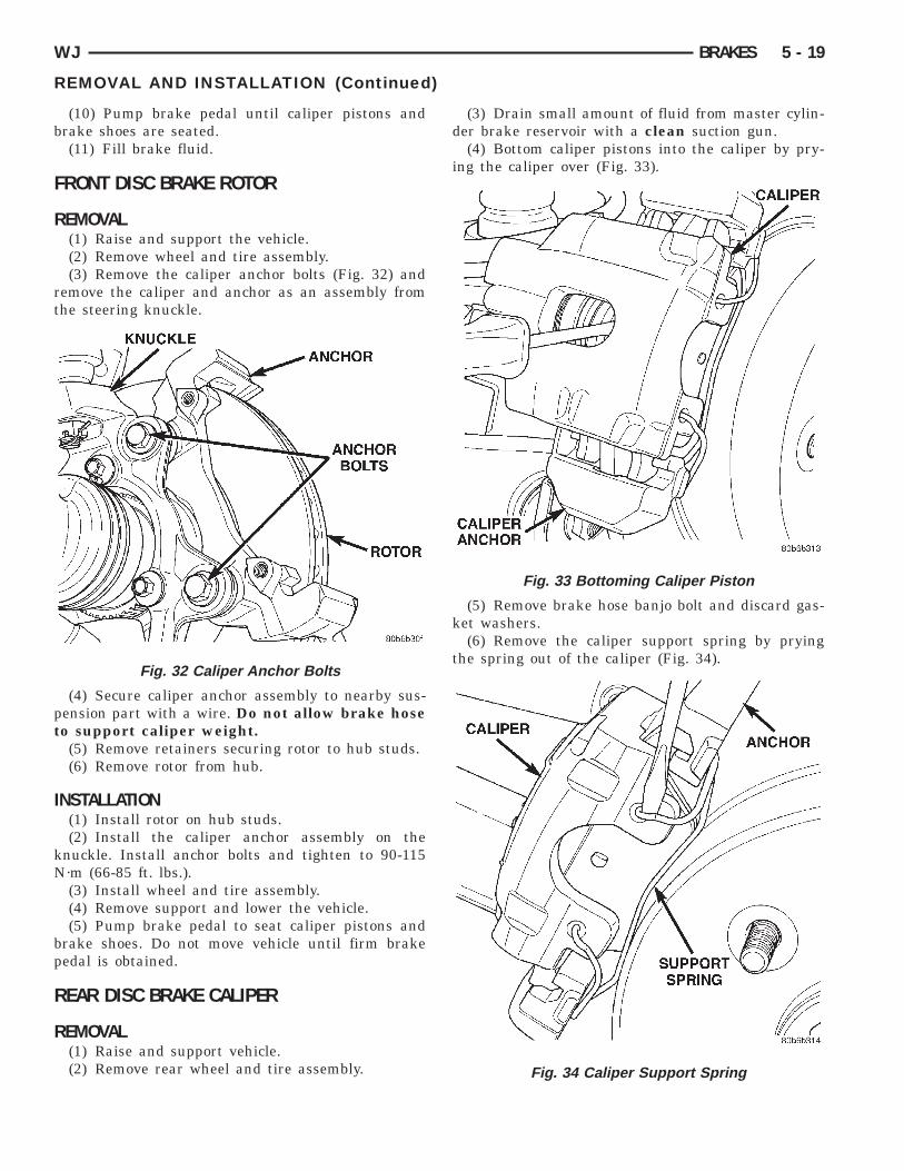
(10) Pump brake pedal until caliper pistons andrake shoes are seated.(11) Fill brake fluid.
RONT DISC BRAKE ROTOR
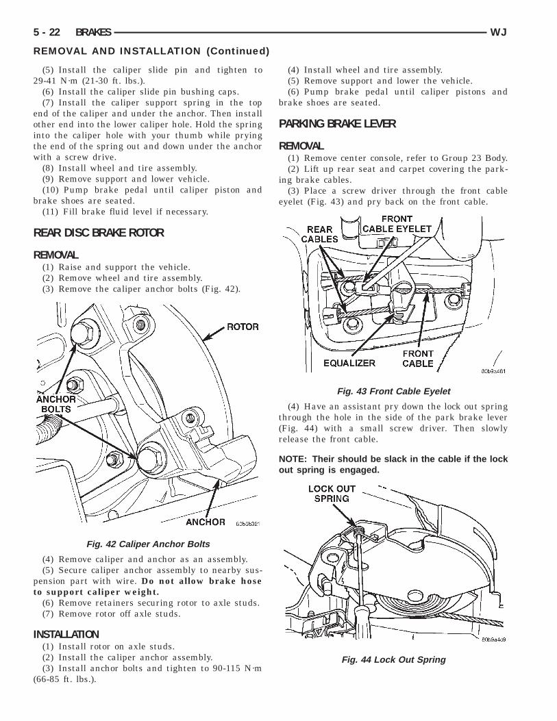
EMOVAL(1) Raise and support the vehicle.(2) Remove wheel and tire assembly.(3) Remove the caliper anchor bolts (Fig. 32) and
emove the caliper and anchor as an assembly fromhe steering knuckle.
(4) Secure caliper anchor assembly to nearby sus-ension part with a wire. Do not allow brake hoseo support caliper weight.
(5) Remove retainers securing rotor to hub studs.(6) Remove rotor from hub.
NSTALLATION(1) Install rotor on hub studs.(2) Install the caliper anchor assembly on the
nuckle. Install anchor bolts and tighten to 90-115·m (66-85 ft. lbs.).(3) Install wheel and tire assembly.(4) Remove support and lower the vehicle.(5) Pump brake pedal to seat caliper pistons and
rake shoes. Do not move vehicle until firm brakeedal is obtained.
EAR DISC BRAKE CALIPER
EMOVAL(1) Raise and support vehicle.(2) Remove rear wheel and tire assembly.
Fig. 32 Caliper Anchor Bolts
(3) Drain small amount of fluid from master cylin-der brake reservoir with a clean suction gun.
(4) Bottom caliper pistons into the caliper by pry-ing the caliper over (Fig. 33).
(5) Remove brake hose banjo bolt and discard gas-ket washers.
(6) Remove the caliper support spring by pryingthe spring out of the caliper (Fig. 34).
Fig. 33 Bottoming Caliper Piston
Fig. 34 Caliper Support Spring
r
I
wv
i
t
r
5 - 20 BRAKES WJ
REMOVAL AND INSTALLATION (Continued)
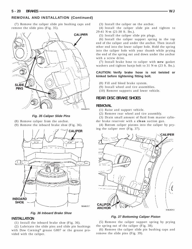
(7) Remove the caliper slide pin bushing caps andemove the slide pins (Fig. 35).
(8) Remove caliper from the anchor.(9) Remove the inboard brake shoe (Fig. 36).
NSTALLATION(1) Install the inboard brake shoe (Fig. 36).(2) Lubricate the slide pins and slide pin bushingsith Dow Corningt grease G807 or the grease pro-ided with the caliper.
Fig. 35 Caliper Slide Pins
Fig. 36 Inboard Brake Shoe
(3) Install the caliper on the anchor.(4) Install the caliper slide pin and tighten to
29-41 N·m (21-30 ft. lbs.).(5) Install the caliper slide pin plugs.(6) Install the caliper support spring in the top
end of the caliper and under the anchor. Then installother end into the lower caliper hole. Hold the springinto the caliper hole with your thumb while pryingthe end of the spring out and down under the anchorwith a screw drive.
(7) Install brake hose to caliper with new gasketwashers and tighten banjo bolt to 31 N·m (23 ft. lbs.).
CAUTION: Verify brake hose is not twisted orkinked before tightening fitting bolt.
(8) Fill and bleed brake system.(9) Install wheel and tire assemblies.(10) Remove supports and lower vehicle.
REAR DISC BRAKE SHOES
REMOVAL(1) Raise and support vehicle.(2) Remove rear wheel and tire assembly.(3) Drain small amount of fluid from master cylin-
der brake reservoir with a clean suction gun.(4) Bottom caliper pistons into the caliper by pry-
ng the caliper over (Fig. 37).
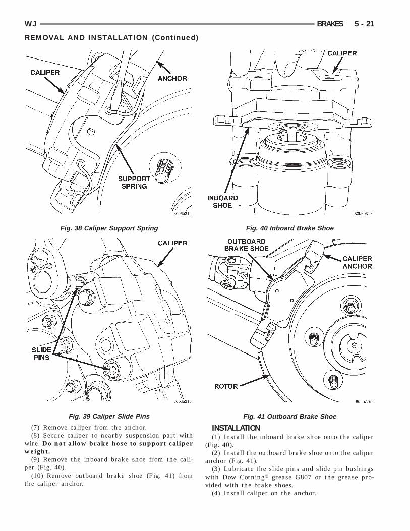
(5) Remove the caliper support spring by pryinghe spring out of the caliper (Fig. 38).
(6) Remove the caliper slide pin bushing caps andemove the slide pins (Fig. 39).
Fig. 37 Bottoming Caliper Piston
ww
p
t v
WJ BRAKES 5 - 21
REMOVAL AND INSTALLATION (Continued)
(7) Remove caliper from the anchor.(8) Secure caliper to nearby suspension part withire. Do not allow brake hose to support calipereight.(9) Remove the inboard brake shoe from the cali-
er (Fig. 40).(10) Remove outboard brake shoe (Fig. 41) from
he caliper anchor.
Fig. 38 Caliper Support Spring
Fig. 39 Caliper Slide Pins
INSTALLATION(1) Install the inboard brake shoe onto the caliper
(Fig. 40).(2) Install the outboard brake shoe onto the caliper
anchor (Fig. 41).(3) Lubricate the slide pins and slide pin bushings
with Dow Corningt grease G807 or the grease pro-ided with the brake shoes.(4) Install caliper on the anchor.
Fig. 40 Inboard Brake Shoe
Fig. 41 Outboard Brake Shoe
2
eoitw
b
R
R
pt
I
(
5 - 22 BRAKES WJ
REMOVAL AND INSTALLATION (Continued)
(5) Install the caliper slide pin and tighten to9-41 N·m (21-30 ft. lbs.).(6) Install the caliper slide pin bushing caps.(7) Install the caliper support spring in the top
nd of the caliper and under the anchor. Then installther end into the lower caliper hole. Hold the springnto the caliper hole with your thumb while pryinghe end of the spring out and down under the anchorith a screw drive.(8) Install wheel and tire assembly.(9) Remove support and lower vehicle.(10) Pump brake pedal until caliper piston and
rake shoes are seated.(11) Fill brake fluid level if necessary.
EAR DISC BRAKE ROTOR
EMOVAL(1) Raise and support the vehicle.(2) Remove wheel and tire assembly.(3) Remove the caliper anchor bolts (Fig. 42).
(4) Remove caliper and anchor as an assembly.(5) Secure caliper anchor assembly to nearby sus-
ension part with wire. Do not allow brake hoseo support caliper weight.
(6) Remove retainers securing rotor to axle studs.(7) Remove rotor off axle studs.
NSTALLATION(1) Install rotor on axle studs.(2) Install the caliper anchor assembly.(3) Install anchor bolts and tighten to 90-115 N·m
Fig. 42 Caliper Anchor Bolts
66-85 ft. lbs.).
(4) Install wheel and tire assembly.(5) Remove support and lower the vehicle.(6) Pump brake pedal until caliper pistons and
brake shoes are seated.
PARKING BRAKE LEVER
REMOVAL(1) Remove center console, refer to Group 23 Body.(2) Lift up rear seat and carpet covering the park-
ing brake cables.(3) Place a screw driver through the front cable
eyelet (Fig. 43) and pry back on the front cable.
(4) Have an assistant pry down the lock out springthrough the hole in the side of the park brake lever(Fig. 44) with a small screw driver. Then slowlyrelease the front cable.
NOTE: Their should be slack in the cable if the lockout spring is engaged.
Fig. 43 Front Cable Eyelet
Fig. 44 Lock Out Spring

n
l
wi
a
a
I
sb
i
WJ BRAKES 5 - 23
REMOVAL AND INSTALLATION (Continued)
(5) Disconnect parking brake switch wiring con-ector.(6) Disengage front cable end from parking brake
ever.(7) Compress the cable retainer with a 13 mmrench (Fig. 45) and remove the cable from the park-
ng brake lever bracket.
(8) Remove the park brake lever mounting nutsnd console bracket. (Fig. 46).(9) Lift the lever assembly off the mounting studs
nd pull the front cable out of the lever bracket.
NSTALLATION(1) Install the lever assembly on the mounting
tuds while feeding the front cable into the leverracket.(2) Install the console bracket (Fig. 46) and mount-
ng nuts.(3) Engage the front cable end to the lever.(4) Connect parking brake switch wire connector.(5) Pull on the lever to release the lock out spring.(6) Install center console, refer to Group 23 Body.(7) Fold down the rear carpet cover and rear seat.
Fig. 45 Parking Brake Lever Bracket
Fig. 46 Parking Brake Lever Mounting
FRONT PARKING BRAKE CABLE
REMOVAL(1) Remove center console, refer to Group 23 Body.(2) Lift up rear seat and carpet covering the park-
ing brake cables.(3) Place a screw driver through the front cable
eyelet (Fig. 47) and pry back on the front cable.
(4) Have an assistant pry down the lock out springthrough the hole in the side of the park brake lever(Fig. 48) with a small screw driver. Then slowlyrelease the front cable.
NOTE: Their should be slack in the cable if the lockout spring is engaged.
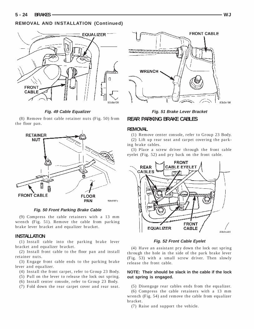
(5) Disengage front cable end from the equalizer(Fig. 49).
(6) Disengage front cable end from the parkingbrake lever.
(7) Remove the front carpet, refer to Group 23Body.
Fig. 47 Front Cable Eyelet
Fig. 48 Lock Out Spring
t
wb
I
b
r
l
5 - 24 BRAKES WJ
REMOVAL AND INSTALLATION (Continued)
(8) Remove front cable retainer nuts (Fig. 50) fromhe floor pan.
(9) Compress the cable retainers with a 13 mmrench (Fig. 51). Remove the cable from parkingrake lever bracket and equalizer bracket.
NSTALLATION(1) Install cable into the parking brake lever
racket and equalizer bracket.(2) Install front cable to the floor pan and install
etainer nuts.(3) Engage front cable ends to the parking brake
ever and equalizer.(4) Install the front carpet, refer to Group 23 Body.(5) Pull on the lever to release the lock out spring.(6) Install center console, refer to Group 23 Body.(7) Fold down the rear carpet cover and rear seat.
Fig. 49 Cable Equalizer
Fig. 50 Front Parking Brake Cable
REAR PARKING BRAKE CABLES
REMOVAL(1) Remove center console, refer to Group 23 Body.(2) Lift up rear seat and carpet covering the park-
ing brake cables.(3) Place a screw driver through the front cable
eyelet (Fig. 52) and pry back on the front cable.
(4) Have an assistant pry down the lock out springthrough the hole in the side of the park brake lever(Fig. 53) with a small screw driver. Then slowlyrelease the front cable.
NOTE: Their should be slack in the cable if the lockout spring is engaged.
(5) Disengage rear cables ends from the equalizer.(6) Compress the cable retainers with a 13 mm
wrench (Fig. 54) and remove the cable from equalizerbracket.
(7) Raise and support the vehicle.
Fig. 51 Brake Lever Bracket
Fig. 52 Front Cable Eyelet

r
5
t
a
wt
I
me
b
b
WJ BRAKES 5 - 25
REMOVAL AND INSTALLATION (Continued)
(8) Remove the wheel and tire assemblies.(9) Remove the brake calipers, caliper anchors and
otors.(10) Remove the ABS sensor wiring harness (Fig.
5) from the rear brake cables.(11) Remove the cable retainer bolts (Fig. 55) from
he rear spring pads.(12) Pull the cables out of the upper suspension
rm brackets.(13) Push the cable in and lift up the end of cableith a small screw driver to disengage the cable from
he parking brake actuator (Fig. 56).(14) Remove the cable from the vehicle.
NSTALLATION(1) Install the cables through the caliper anchorount. Then push the end of cable strand in to
ngage the cable end to the parking brake actuator.(2) Feed the other end of the cables through the
ody and into the equalizer bracket (Fig. 57).(3) Push the cables into the upper suspension arm
rackets.
Fig. 53 Lock Out Spring
Fig. 54 Cable Retainers
(4) Install the cable retainer bolts to the rearspring pads.
(5) Install the ABS sensor wiring harness to therear brake cables.
(6) Install the rotors, caliper anchors and brakecalipers.
(7) Install the wheel and tire assemblies.(8) Remove support and lower the vehicle.(9) Engage the cable ends into the parking brake
equalizer.(10) Pull on the lever to release the lock out
spring.(11) Install center console, refer to Group 23 Body.(12) Fold down the rear carpet cover and rear seat.(13) Verify parking brake operation.
Fig. 55 Left Rear Parking Brake Cable
Fig. 56 Parking Brake Actuator

P
R
d
bsd
s
s
6n
Fig. 59 Retracting Parking Brake Shoes
Fig. 61 Upper Spring
5 - 26 BRAKES WJ
REMOVAL AND INSTALLATION (Continued)
ARKING BRAKE SHOES
EMOVAL(1) Lock out park brake lever (Fig. 58).
(2) Raise vehicle.(3) Remove rear wheel and tire assembly.(4) Remove caliper and anchor as an assembly.(5) Remove rubber access plug from back of rear
isc brake splash shield.(6) If necessary retract parking brake shoes with
rake adjuster tool (Fig. 59). Position tool at top oftar wheel and rotate wheel downward in clockwiseirection (while facing front of vehicle).(7) Remove rotor from axle hub flange.(8) Remove the lower shoe to shoe spring/adjuster
pring with needle nose pliers (Fig. 60).(9) Remove the upper shoe to shoe spring/return
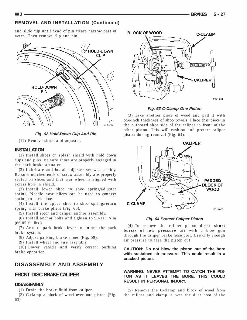
pring with brake pliers (Fig. 61).(10) Remove shoe hold-down clips and pins (Fig.
2). Clip is held in place by pin which fits in clipotch. To remove clip, first push clip ends together
Fig. 57 Equalizer Bracket
Fig. 58 Lock Out Spring
Fig. 60 Lower Spring
an
I
ct
Bsa
ss
s
(
b
b
D
F
D
6
WJ BRAKES 5 - 27
REMOVAL AND INSTALLATION (Continued)
nd slide clip until head of pin clears narrow part ofotch. Then remove clip and pin.
(11) Remove shoes and adjuster.
NSTALLATION(1) Install shoes on splash shield with hold down
lips and pins. Be sure shoes are properly engaged inhe park brake actuator.
(2) Lubricate and install adjuster screw assembly.e sure notched ends of screw assembly are properlyeated on shoes and that star wheel is aligned withccess hole in shield.(3) Install lower shoe to shoe spring/adjuster
pring. Needle nose pliers can be used to connectpring to each shoe.(4) Install the upper shoe to shoe spring/return
pring with brake pliers (Fig. 60).(5) Install rotor and caliper anchor assembly.(6) Install anchor bolts and tighten to 90-115 N·m
66-85 ft. lbs.).(7) Actuate park brake lever to unlock the park
rake system.(8) Adjust parking brake shoes (Fig. 59).(9) Install wheel and tire assembly.(10) Lower vehicle and verify correct parking
rake operation.
ISASSEMBLY AND ASSEMBLY
RONT DISC BRAKE CALIPER
ISASSEMBLY(1) Drain the brake fluid from caliper.(2) C-clamp a block of wood over one piston (Fig.
3).
Fig. 62 Hold-Down Clip And Pin
(3) Take another piece of wood and pad it withone-inch thickness of shop towels. Place this piece inthe outboard shoe side of the caliper in front of theother piston. This will cushion and protect caliperpiston during removal (Fig. 64).
(4) To remove the caliper piston direct shortbursts of low pressure air with a blow gunthrough the caliper brake hose port. Use only enoughair pressure to ease the piston out.
CAUTION: Do not blow the piston out of the borewith sustained air pressure. This could result in acracked piston.
WARNING: NEVER ATTEMPT TO CATCH THE PIS-TON AS IT LEAVES THE BORE. THIS COULDRESULT IN PERSONAL INJURY.
(5) Remove the C-clamp and block of wood fromthe caliper and clamp it over the dust boot of the
Fig. 63 C-Clamp One Piston
Fig. 64 Protect Caliper Piston
fb
o
c
t
d
Ci
A
Cp
5 - 28 BRAKES WJ
DISASSEMBLY AND ASSEMBLY (Continued)
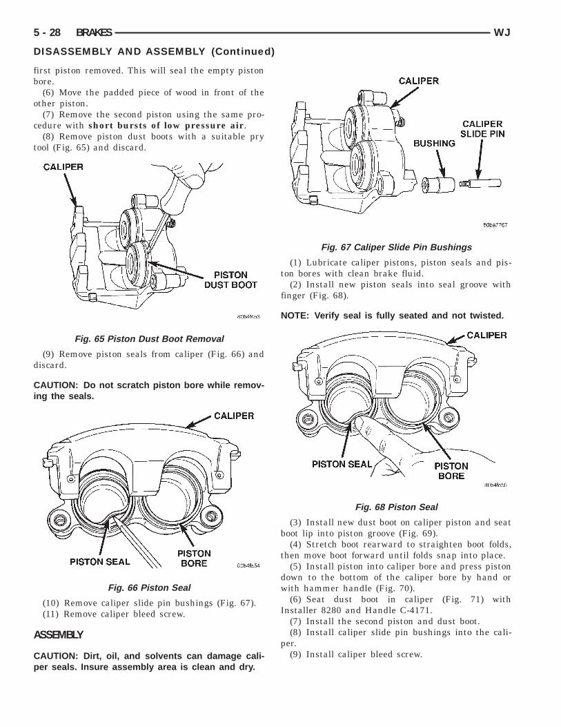
irst piston removed. This will seal the empty pistonore.(6) Move the padded piece of wood in front of the
ther piston.(7) Remove the second piston using the same pro-
edure with short bursts of low pressure air.(8) Remove piston dust boots with a suitable pry
ool (Fig. 65) and discard.
(9) Remove piston seals from caliper (Fig. 66) andiscard.
AUTION: Do not scratch piston bore while remov-ng the seals.
(10) Remove caliper slide pin bushings (Fig. 67).(11) Remove caliper bleed screw.
SSEMBLY
AUTION: Dirt, oil, and solvents can damage cali-er seals. Insure assembly area is clean and dry.
Fig. 65 Piston Dust Boot Removal
Fig. 66 Piston Seal
(1) Lubricate caliper pistons, piston seals and pis-ton bores with clean brake fluid.
(2) Install new piston seals into seal groove withfinger (Fig. 68).
NOTE: Verify seal is fully seated and not twisted.
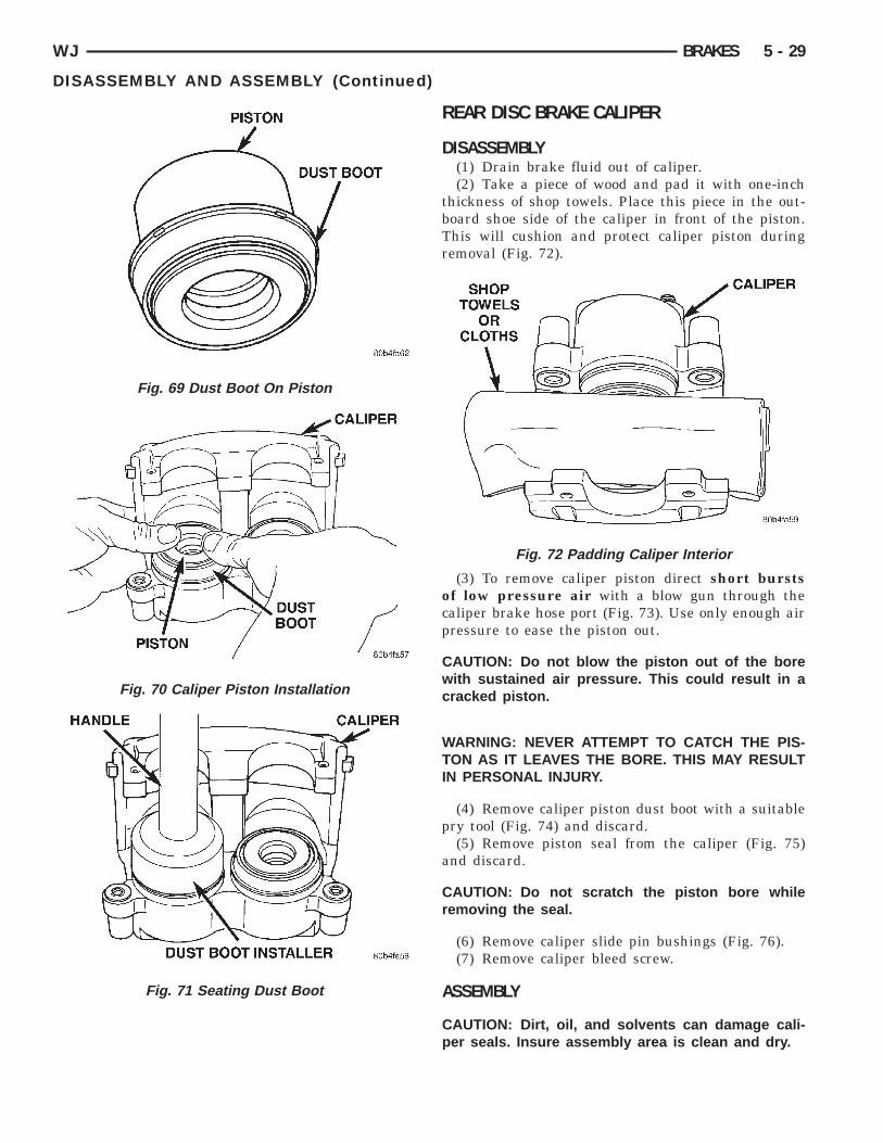
(3) Install new dust boot on caliper piston and seatboot lip into piston groove (Fig. 69).
(4) Stretch boot rearward to straighten boot folds,then move boot forward until folds snap into place.
(5) Install piston into caliper bore and press pistondown to the bottom of the caliper bore by hand orwith hammer handle (Fig. 70).
(6) Seat dust boot in caliper (Fig. 71) withInstaller 8280 and Handle C-4171.
(7) Install the second piston and dust boot.(8) Install caliper slide pin bushings into the cali-
per.(9) Install caliper bleed screw.
Fig. 67 Caliper Slide Pin Bushings
Fig. 68 Piston Seal
WJ BRAKES 5 - 29
DISASSEMBLY AND ASSEMBLY (Continued)
Fig. 69 Dust Boot On Piston
Fig. 70 Caliper Piston Installation
Fig. 71 Seating Dust Boot
REAR DISC BRAKE CALIPER
DISASSEMBLY(1) Drain brake fluid out of caliper.(2) Take a piece of wood and pad it with one-inch
thickness of shop towels. Place this piece in the out-board shoe side of the caliper in front of the piston.This will cushion and protect caliper piston duringremoval (Fig. 72).
(3) To remove caliper piston direct short burstsof low pressure air with a blow gun through thecaliper brake hose port (Fig. 73). Use only enough airpressure to ease the piston out.
CAUTION: Do not blow the piston out of the borewith sustained air pressure. This could result in acracked piston.
WARNING: NEVER ATTEMPT TO CATCH THE PIS-TON AS IT LEAVES THE BORE. THIS MAY RESULTIN PERSONAL INJURY.
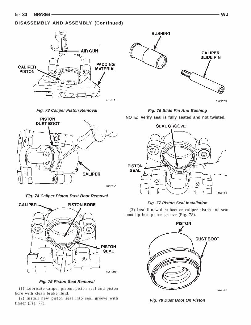
(4) Remove caliper piston dust boot with a suitablepry tool (Fig. 74) and discard.
(5) Remove piston seal from the caliper (Fig. 75)and discard.
CAUTION: Do not scratch the piston bore whileremoving the seal.
(6) Remove caliper slide pin bushings (Fig. 76).(7) Remove caliper bleed screw.
ASSEMBLY
CAUTION: Dirt, oil, and solvents can damage cali-per seals. Insure assembly area is clean and dry.
Fig. 72 Padding Caliper Interior
b
f
5 - 30 BRAKES WJ
DISASSEMBLY AND ASSEMBLY (Continued)
(1) Lubricate caliper piston, piston seal and pistonore with clean brake fluid.(2) Install new piston seal into seal groove with
inger (Fig. 77).
Fig. 73 Caliper Piston Removal
Fig. 74 Caliper Piston Dust Boot Removal
Fig. 75 Piston Seal Removal
NOTE: Verify seal is fully seated and not twisted.
(3) Install new dust boot on caliper piston and seatboot lip into piston groove (Fig. 78).
Fig. 76 Slide Pin And Bushing
Fig. 77 Piston Seal Installation
Fig. 78 Dust Boot On Piston
t
dw
a
p
C
C
C
fdp
WJ BRAKES 5 - 31
DISASSEMBLY AND ASSEMBLY (Continued)
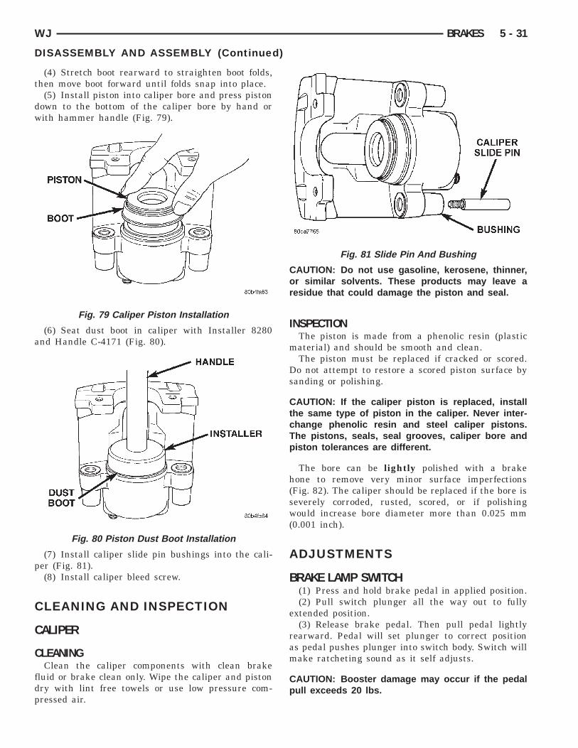
(4) Stretch boot rearward to straighten boot folds,hen move boot forward until folds snap into place.
(5) Install piston into caliper bore and press pistonown to the bottom of the caliper bore by hand orith hammer handle (Fig. 79).
(6) Seat dust boot in caliper with Installer 8280nd Handle C-4171 (Fig. 80).
(7) Install caliper slide pin bushings into the cali-er (Fig. 81).(8) Install caliper bleed screw.
LEANING AND INSPECTION
ALIPER
LEANINGClean the caliper components with clean brake
luid or brake clean only. Wipe the caliper and pistonry with lint free towels or use low pressure com-ressed air.
Fig. 79 Caliper Piston Installation
Fig. 80 Piston Dust Boot Installation
CAUTION: Do not use gasoline, kerosene, thinner,or similar solvents. These products may leave aresidue that could damage the piston and seal.
INSPECTIONThe piston is made from a phenolic resin (plastic
material) and should be smooth and clean.The piston must be replaced if cracked or scored.
Do not attempt to restore a scored piston surface bysanding or polishing.
CAUTION: If the caliper piston is replaced, installthe same type of piston in the caliper. Never inter-change phenolic resin and steel caliper pistons.The pistons, seals, seal grooves, caliper bore andpiston tolerances are different.
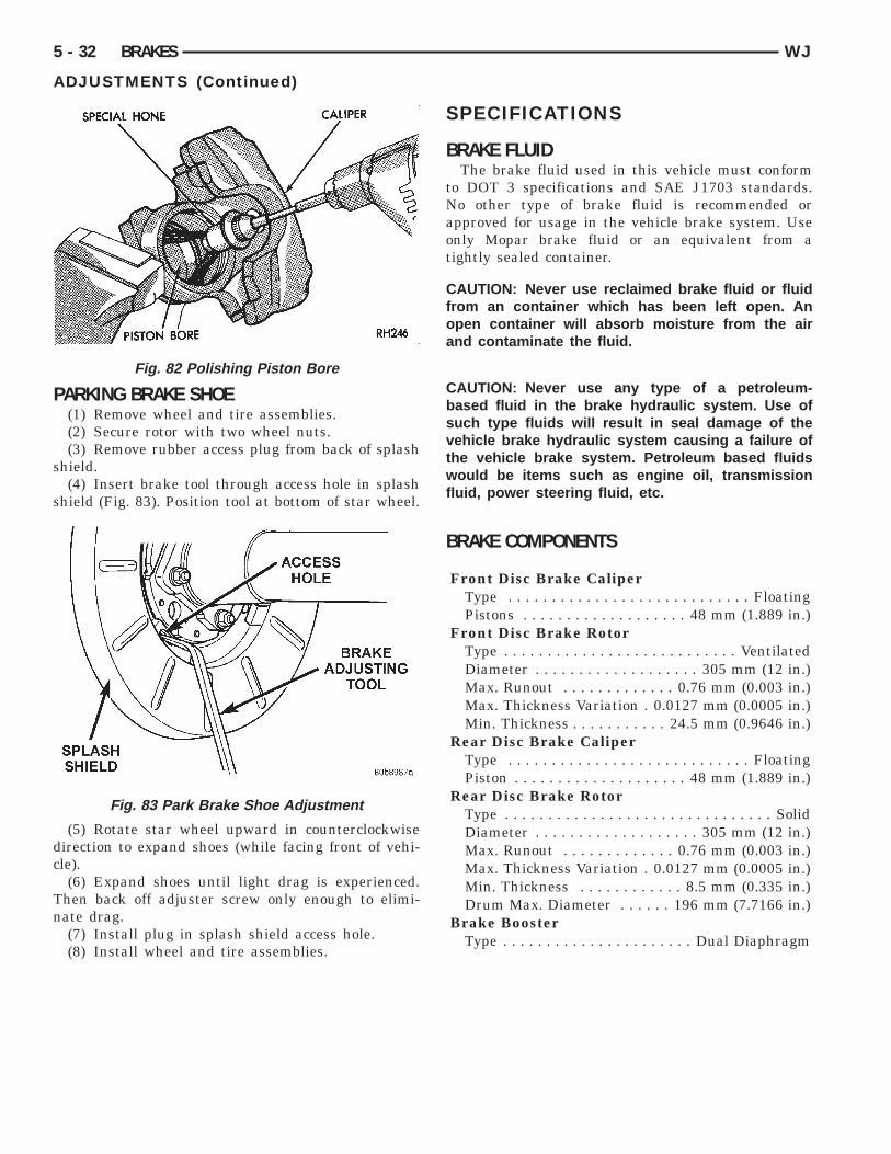
The bore can be lightly polished with a brakehone to remove very minor surface imperfections(Fig. 82). The caliper should be replaced if the bore isseverely corroded, rusted, scored, or if polishingwould increase bore diameter more than 0.025 mm(0.001 inch).
ADJUSTMENTS
BRAKE LAMP SWITCH(1) Press and hold brake pedal in applied position.(2) Pull switch plunger all the way out to fully
extended position.(3) Release brake pedal. Then pull pedal lightly
rearward. Pedal will set plunger to correct positionas pedal pushes plunger into switch body. Switch willmake ratcheting sound as it self adjusts.
CAUTION: Booster damage may occur if the pedalpull exceeds 20 lbs.
Fig. 81 Slide Pin And Bushing
P
s
s
dc
Tn
5 - 32 BRAKES WJ
ADJUSTMENTS (Continued)
ARKING BRAKE SHOE(1) Remove wheel and tire assemblies.(2) Secure rotor with two wheel nuts.(3) Remove rubber access plug from back of splash
hield.(4) Insert brake tool through access hole in splash
hield (Fig. 83). Position tool at bottom of star wheel.
(5) Rotate star wheel upward in counterclockwiseirection to expand shoes (while facing front of vehi-le).(6) Expand shoes until light drag is experienced.
hen back off adjuster screw only enough to elimi-ate drag.(7) Install plug in splash shield access hole.(8) Install wheel and tire assemblies.
Fig. 82 Polishing Piston Bore
Fig. 83 Park Brake Shoe Adjustment
SPECIFICATIONS
BRAKE FLUIDThe brake fluid used in this vehicle must conform
to DOT 3 specifications and SAE J1703 standards.No other type of brake fluid is recommended orapproved for usage in the vehicle brake system. Useonly Mopar brake fluid or an equivalent from atightly sealed container.
CAUTION: Never use reclaimed brake fluid or fluidfrom an container which has been left open. Anopen container will absorb moisture from the airand contaminate the fluid.
CAUTION: Never use any type of a petroleum-based fluid in the brake hydraulic system. Use ofsuch type fluids will result in seal damage of thevehicle brake hydraulic system causing a failure ofthe vehicle brake system. Petroleum based fluidswould be items such as engine oil, transmissionfluid, power steering fluid, etc.
BRAKE COMPONENTS
Front Disc Brake CaliperType . . . . . . . . . . . . . . . . . . . . . . . . . . . . FloatingPistons . . . . . . . . . . . . . . . . . . . 48 mm (1.889 in.)
Front Disc Brake RotorType . . . . . . . . . . . . . . . . . . . . . . . . . . . VentilatedDiameter . . . . . . . . . . . . . . . . . . . 305 mm (12 in.)Max. Runout . . . . . . . . . . . . . 0.76 mm (0.003 in.)Max. Thickness Variation . 0.0127 mm (0.0005 in.)Min. Thickness . . . . . . . . . . . 24.5 mm (0.9646 in.)
Rear Disc Brake CaliperType . . . . . . . . . . . . . . . . . . . . . . . . . . . . FloatingPiston . . . . . . . . . . . . . . . . . . . . 48 mm (1.889 in.)
Rear Disc Brake RotorType . . . . . . . . . . . . . . . . . . . . . . . . . . . . . . . SolidDiameter . . . . . . . . . . . . . . . . . . . 305 mm (12 in.)Max. Runout . . . . . . . . . . . . . 0.76 mm (0.003 in.)Max. Thickness Variation . 0.0127 mm (0.0005 in.)Min. Thickness . . . . . . . . . . . . 8.5 mm (0.335 in.)Drum Max. Diameter . . . . . . 196 mm (7.7166 in.)
Brake BoosterType . . . . . . . . . . . . . . . . . . . . . . Dual Diaphragm

T
WJ BRAKES 5 - 33
SPECIFICATIONS (Continued)
ORQUE CHART
DESCRIPTION TORQUEBrake Pedal
Support Bolt . . . . . . . . . 23-34 N·m (17-25 ft. lbs.)Pivot Nut . . . . . . . . . . . . 27-35 N·m (20-26 ft. lbs.)
Brake BoosterMounting Nuts . . . . . . . . . . . . 39 N·m (29 ft. lbs.)
Master CylinderMounting Nuts . . . . . . . . . . . . 25 N·m (18 ft. lbs.)Primary Brake Line . . . . . . . 16 N·m (144 in. lbs.)Secondary Brake Line . . . . . 16 N·m (144 in. lbs.)
Front CaliperSlide Pins . . . . . . . . . . . 29-41 N·m (21-30 ft. lbs.)Anchor Bolts . . . . . . . . 90-115 N·m (66-85 ft. lbs.)Brake Hose Banjo Bolt . . . . . . 31 N·m (23 ft. lbs.)Bleed Screw . . . . . . . . . . . . . 16 N·m (144 in. lbs.)
Rear CaliperSlide Pins . . . . . . . . . . . 29-41 N·m (21-30 ft. lbs.)Anchor Bolts . . . . . . . . 90-115 N·m (66-85 ft. lbs.)Brake Hose Banjo Bolt . . . . . . 31 N·m (23 ft. lbs.)Bleed Screw . . . . . . . . . . . . . 16 N·m (144 in. lbs.)
SPECIAL TOOLS
BASE BRAKES
Installer Caliper Dust Boot 8280
Handle C-4171
Adapter Pressure Bleeder 6921

D
D
D
A
c
TaAccc
5 - 34 BRAKES WJ
ANTILOCK BRAKES
INDEX
page page
S
R
S
ESCRIPTION AND OPERATIONABS WARNING LAMP . . . . . . . . . . . . . . . . . . . . 36ANTILOCK BRAKE SYSTEM . . . . . . . . . . . . . . . 34CONTROLLER ANTILOCK BRAKES . . . . . . . . . . 35G-SWITCH . . . . . . . . . . . . . . . . . . . . . . . . . . . . . 36HYDRAULIC CONTROL UNIT . . . . . . . . . . . . . . . 35WHEEL SPEED SENSORS AND
TONE WHEEL . . . . . . . . . . . . . . . . . . . . . . . . . 36IAGNOSIS AND TESTINGANTILOCK BRAKES . . . . . . . . . . . . . . . . . . . . . . 36
ERVICE PROCEDURESBLEEDING ABS BRAKE SYSTEM . . . . . . . . . . . 37EMOVAL AND INSTALLATIONCONTROLLER ANTILOCK BRAKES . . . . . . . . . . 37FRONT WHEEL SPEED SENSOR . . . . . . . . . . . 38G-SWITCH . . . . . . . . . . . . . . . . . . . . . . . . . . . . . 39HYDRAULIC CONTROL UNIT/CONTROLLER
ANTILOCK BRAKES . . . . . . . . . . . . . . . . . . . . 37REAR WHEEL SPEED SENSOR . . . . . . . . . . . . 38PECIFICATIONS
TORQUE CHART . . . . . . . . . . . . . . . . . . . . . . . . 40ESCRIPTION AND OPERATION
NTILOCK BRAKE SYSTEMThe antilock brake system (ABS) is an electroni-
ally operated, all wheel brake control system.The hydraulic system is a three channel design.
he front wheel brakes are controlled individuallynd the rear wheel brakes in tandem (Fig. 1). TheBS electrical system is separate from other electri-al circuits in the vehicle. A specially programmedontroller antilock brake unit operates the systemomponents.
ABS system major components include:• Controller Antilock Brakes (CAB)• Hydraulic Control Unit (HCU)
Fig. 1 Antilock Brake System
• Wheel Speed Sensors (WSS)• G-Switch• ABS Warning LampThe purpose of the antilock system is to prevent
wheel lockup during periods of high wheel slip. Pre-venting lockup helps maintain vehicle braking actionand steering control.
The antilock CAB activates the system wheneversensor signals indicate periods of high wheel slip.High wheel slip can be described as the point wherewheel rotation begins approaching 20 to 30 percent ofactual vehicle speed during braking. Periods of highwheel slip occur when brake stops involve high pedalpressure and rate of vehicle deceleration.
Battery voltage is supplied to the CAB ignition ter-minal when the ignition switch is turned to Run posi-tion. The CAB performs a system initializationprocedure at this point. Initialization consists of astatic and dynamic self check of system electricalcomponents.
The static check occurs after the ignition switch isturned to Run position. The dynamic check occurswhen vehicle road speed reaches approximately 30kph (18 mph). During the dynamic check, the CABbriefly cycles the pump and solenoids to verify oper-ation.
If an ABS component exhibits a fault during ini-tialization, the CAB illuminates the amber warninglamp and registers a fault code in the microprocessormemory.
ELECTRONIC BRAKE DISTRIBUTIONThe electronic brake distribution (EBD) functions
like a rear proportioning valve. The EBD system usesthe ABS system to control the slip of the rear wheelsin partial braking range. The braking force of therear wheels is controlled electronically by using the
inlet and outlet valves located in the HCU.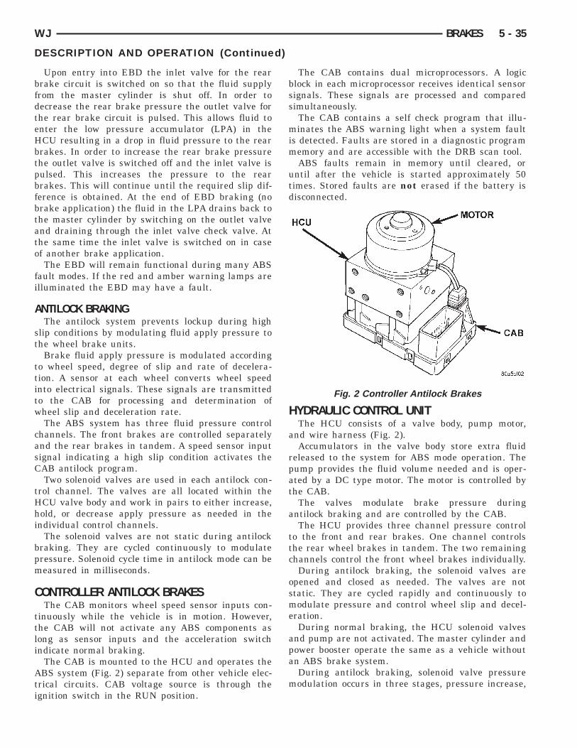
bfdteHbtpbfbtato
fi
A
st
ttitw
casC
tHhi
bpm
C
ttli
Ati
WJ BRAKES 5 - 35
DESCRIPTION AND OPERATION (Continued)
Upon entry into EBD the inlet valve for the rearrake circuit is switched on so that the fluid supplyrom the master cylinder is shut off. In order toecrease the rear brake pressure the outlet valve forhe rear brake circuit is pulsed. This allows fluid tonter the low pressure accumulator (LPA) in theCU resulting in a drop in fluid pressure to the rearrakes. In order to increase the rear brake pressurehe outlet valve is switched off and the inlet valve isulsed. This increases the pressure to the rearrakes. This will continue until the required slip dif-erence is obtained. At the end of EBD braking (norake application) the fluid in the LPA drains back tohe master cylinder by switching on the outlet valvend draining through the inlet valve check valve. Athe same time the inlet valve is switched on in casef another brake application.The EBD will remain functional during many ABS
ault modes. If the red and amber warning lamps arelluminated the EBD may have a fault.
NTILOCK BRAKINGThe antilock system prevents lockup during high
lip conditions by modulating fluid apply pressure tohe wheel brake units.
Brake fluid apply pressure is modulated accordingo wheel speed, degree of slip and rate of decelera-ion. A sensor at each wheel converts wheel speednto electrical signals. These signals are transmittedo the CAB for processing and determination ofheel slip and deceleration rate.The ABS system has three fluid pressure control
hannels. The front brakes are controlled separatelynd the rear brakes in tandem. A speed sensor inputignal indicating a high slip condition activates theAB antilock program.Two solenoid valves are used in each antilock con-
rol channel. The valves are all located within theCU valve body and work in pairs to either increase,old, or decrease apply pressure as needed in the
ndividual control channels.The solenoid valves are not static during antilock
raking. They are cycled continuously to modulateressure. Solenoid cycle time in antilock mode can beeasured in milliseconds.
ONTROLLER ANTILOCK BRAKESThe CAB monitors wheel speed sensor inputs con-
inuously while the vehicle is in motion. However,he CAB will not activate any ABS components asong as sensor inputs and the acceleration switchndicate normal braking.
The CAB is mounted to the HCU and operates theBS system (Fig. 2) separate from other vehicle elec-
rical circuits. CAB voltage source is through thegnition switch in the RUN position.
The CAB contains dual microprocessors. A logicblock in each microprocessor receives identical sensorsignals. These signals are processed and comparedsimultaneously.
The CAB contains a self check program that illu-minates the ABS warning light when a system faultis detected. Faults are stored in a diagnostic programmemory and are accessible with the DRB scan tool.
ABS faults remain in memory until cleared, oruntil after the vehicle is started approximately 50times. Stored faults are not erased if the battery isdisconnected.
HYDRAULIC CONTROL UNITThe HCU consists of a valve body, pump motor,
and wire harness (Fig. 2).Accumulators in the valve body store extra fluid
released to the system for ABS mode operation. Thepump provides the fluid volume needed and is oper-ated by a DC type motor. The motor is controlled bythe CAB.
The valves modulate brake pressure duringantilock braking and are controlled by the CAB.
The HCU provides three channel pressure controlto the front and rear brakes. One channel controlsthe rear wheel brakes in tandem. The two remainingchannels control the front wheel brakes individually.
During antilock braking, the solenoid valves areopened and closed as needed. The valves are notstatic. They are cycled rapidly and continuously tomodulate pressure and control wheel slip and decel-eration.
During normal braking, the HCU solenoid valvesand pump are not activated. The master cylinder andpower booster operate the same as a vehicle withoutan ABS brake system.
During antilock braking, solenoid valve pressuremodulation occurs in three stages, pressure increase,
Fig. 2 Controller Antilock Brakes
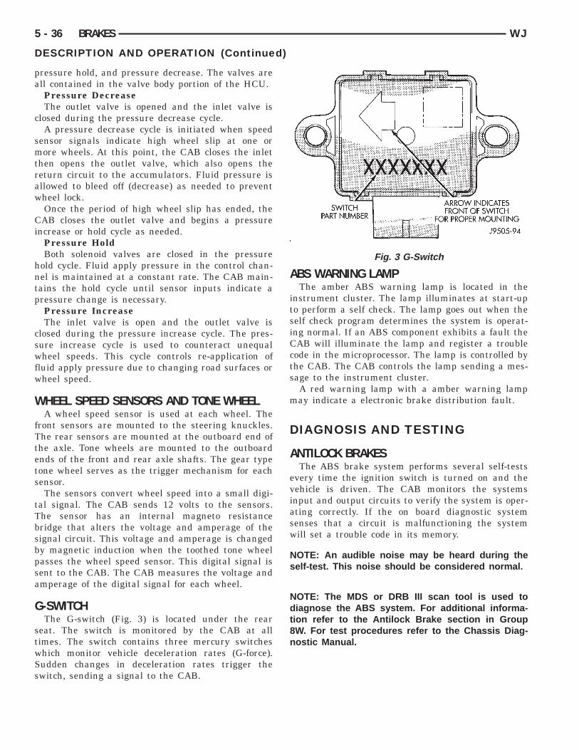
pa
c
smtraw
Ci
hntp
cswfw
W
fTtets
tTbsbpsa
G
stwSs
5 - 36 BRAKES WJ
DESCRIPTION AND OPERATION (Continued)
ressure hold, and pressure decrease. The valves arell contained in the valve body portion of the HCU.Pressure DecreaseThe outlet valve is opened and the inlet valve is
losed during the pressure decrease cycle.A pressure decrease cycle is initiated when speed
ensor signals indicate high wheel slip at one orore wheels. At this point, the CAB closes the inlet
hen opens the outlet valve, which also opens theeturn circuit to the accumulators. Fluid pressure isllowed to bleed off (decrease) as needed to preventheel lock.Once the period of high wheel slip has ended, theAB closes the outlet valve and begins a pressure
ncrease or hold cycle as needed.Pressure HoldBoth solenoid valves are closed in the pressure
old cycle. Fluid apply pressure in the control chan-el is maintained at a constant rate. The CAB main-ains the hold cycle until sensor inputs indicate aressure change is necessary.Pressure IncreaseThe inlet valve is open and the outlet valve is
losed during the pressure increase cycle. The pres-ure increase cycle is used to counteract unequalheel speeds. This cycle controls re-application of
luid apply pressure due to changing road surfaces orheel speed.
HEEL SPEED SENSORS AND TONE WHEELA wheel speed sensor is used at each wheel. The
ront sensors are mounted to the steering knuckles.he rear sensors are mounted at the outboard end ofhe axle. Tone wheels are mounted to the outboardnds of the front and rear axle shafts. The gear typeone wheel serves as the trigger mechanism for eachensor.The sensors convert wheel speed into a small digi-
al signal. The CAB sends 12 volts to the sensors.he sensor has an internal magneto resistanceridge that alters the voltage and amperage of theignal circuit. This voltage and amperage is changedy magnetic induction when the toothed tone wheelasses the wheel speed sensor. This digital signal isent to the CAB. The CAB measures the voltage andmperage of the digital signal for each wheel.
-SWITCHThe G-switch (Fig. 3) is located under the rear
eat. The switch is monitored by the CAB at allimes. The switch contains three mercury switcheshich monitor vehicle deceleration rates (G-force).udden changes in deceleration rates trigger thewitch, sending a signal to the CAB.
ABS WARNING LAMPThe amber ABS warning lamp is located in the
instrument cluster. The lamp illuminates at start-upto perform a self check. The lamp goes out when theself check program determines the system is operat-ing normal. If an ABS component exhibits a fault theCAB will illuminate the lamp and register a troublecode in the microprocessor. The lamp is controlled bythe CAB. The CAB controls the lamp sending a mes-sage to the instrument cluster.
A red warning lamp with a amber warning lampmay indicate a electronic brake distribution fault.
DIAGNOSIS AND TESTING
ANTILOCK BRAKESThe ABS brake system performs several self-tests
every time the ignition switch is turned on and thevehicle is driven. The CAB monitors the systemsinput and output circuits to verify the system is oper-ating correctly. If the on board diagnostic systemsenses that a circuit is malfunctioning the systemwill set a trouble code in its memory.
NOTE: An audible noise may be heard during theself-test. This noise should be considered normal.
NOTE: The MDS or DRB III scan tool is used todiagnose the ABS system. For additional informa-tion refer to the Antilock Brake section in Group8W. For test procedures refer to the Chassis Diag-nostic Manual.
Fig. 3 G-Switch

S
B
icfHir
b
CiC
R
p
R
C
R
t
F
r
r
WJ BRAKES 5 - 37
ERVICE PROCEDURES
LEEDING ABS BRAKE SYSTEMABS system bleeding requires conventional bleed-
ng methods plus use of the DRB scan tool. The pro-edure involves performing a base brake bleeding,ollowed by use of the scan tool to cycle and bleed theCU pump and solenoids. A second base brake bleed-
ng procedure is then required to remove any airemaining in the system.(1) Perform base brake bleeding. Refer to base
rake section for procedure.(2) Connect scan tool to the Data Link Connector.(3) Select ANTILOCK BRAKES, followed by MIS-ELLANEOUS, then ABS BRAKES. Follow the
nstructions displayed. When scan tool displays TESTOMPLETE, disconnect scan tool and proceed.(4) Perform base brake bleeding a second time.efer to base brake section for procedure.(5) Top off master cylinder fluid level and verify
roper brake operation before moving vehicle.
EMOVAL AND INSTALLATION
ONTROLLER ANTILOCK BRAKES
EMOVAL(1) Remove negative battery cable from the bat-
ery.(2) Remove air cleaner housing refer to Group 14
uel System.(3) Pull CAB harness connector release up and
emove connector (Fig. 4).
(4) Remove pump motor connector.(5) Remove CAB mounting bolts (Fig. 5) and
emove the CAB from the HCU.
Fig. 4 CAB Connector Release
INSTALLATION(1) Install the CAB onto the HCU and tighten
mounting bolts to 1.8 N·m (16 in. lbs.).(2) Install pump motor connector.(3) Install CAB harness connector and push down
connector release.(4) Install air cleaner housing.(5) Install negative battery cable to the battery.
HYDRAULIC CONTROL UNIT/CONTROLLERANTILOCK BRAKES
REMOVAL(1) Remove negative battery cable from the bat-
tery.(2) Remove air cleaner housing refer to Group 14
Fuel System.(3) Pull CAB harness connector release up and
remove connector (Fig. 6).(4) Remove the brake lines from the HCU.(5) Remove HCU/CAB side mounting bolt and two
rear mounting bolts (Fig. 7).(6) Remove HCU/CAB assembly from the vehicle.
INSTALLATION(1) Install HCU/CAB assembly into the mounting
bracket and tighten mounting bolts to 12 N·m (9 ft.lbs.).
(2) Install the brake lines to the HCU and tightento 16 N·m (12 ft. lbs.).
(3) Install CAB harness connector and push downconnector release.
(4) Install air cleaner housing.(5) Install negative battery cable to the battery.(6) Bleed base and ABS brake systems.
Fig. 5 CAB Mounting Bolts

F
R
8
8
(
I
sb
b
5 - 38 BRAKES WJ
REMOVAL AND INSTALLATION (Continued)
RONT WHEEL SPEED SENSOR
EMOVAL(1) Raise and support vehicle.(2) Remove front wheel sensor mounting bolt (Fig.
).(3) Remove the sensor from the steering knuckle.(4) Disengage sensor wire from the brackets (Fig.
) on the steering knuckle.(5) Disconnect the sensor from the sensor harness
Fig. 9) and (Fig. 10).(6) Remove sensor and wire.
NSTALLATION(1) Install the sensor on the steering knuckle.(2) Apply Mopar Lock N’ Seal or Loctitet 242 to
ensor mounting bolt. Use new sensor bolt if originalolt is worn or damaged.(3) Install the sensor mounting bolt and tighten
olt to 12-14 N·m (106-124 in. lbs.).
Fig. 6 CAB Connector Release
Fig. 7 HCU/CAB Assembly
(4) Engage grommets on sensor wire to the steer-ing knuckle brackets.
(5) Connect sensor wire to harness connector.(6) Check sensor wire routing. Be sure wire is
clear of all chassis components and is not twisted orkinked at any spot.
(7) Remove support and lower vehicle.
REAR WHEEL SPEED SENSOR
REMOVAL(1) Raise and fold rear seat forward. Then move
carpeting aside for access to rear sensor connectors.(2) Disconnect rear sensor wire at harness connec-
tors (Fig. 11).
Fig. 8 Sensor Location
Fig. 9 Left Sensor Connector
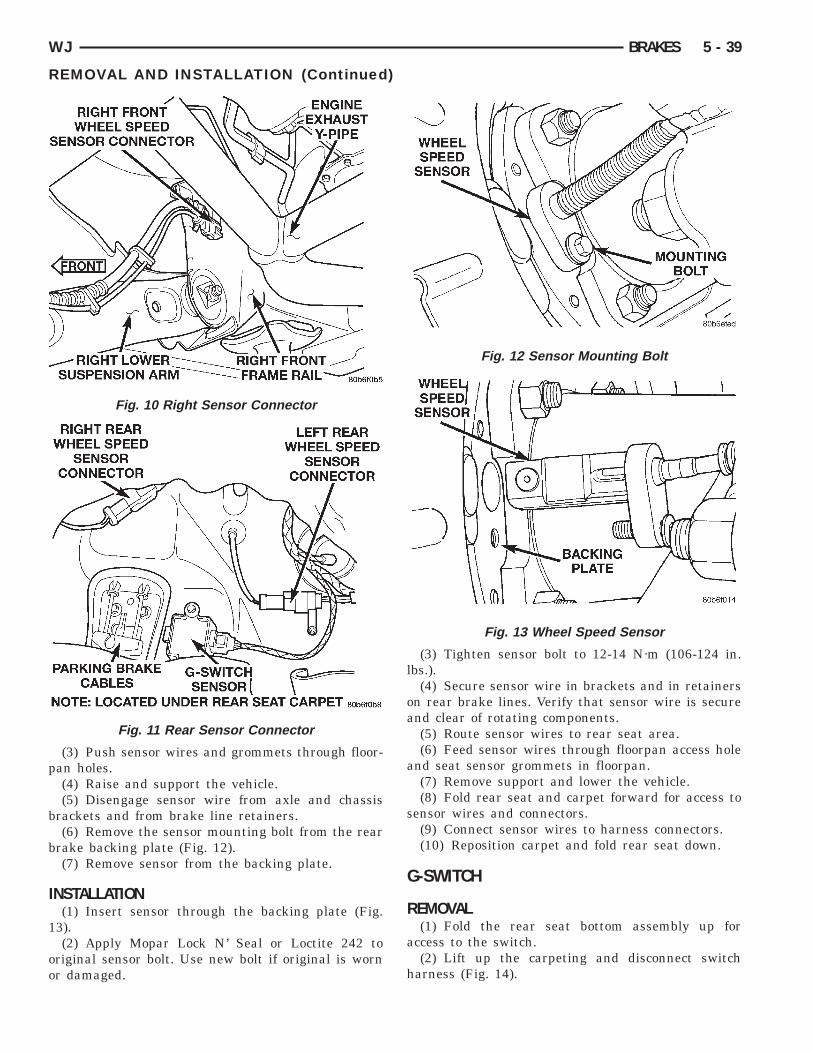
p
b
b
I
1
oo
WJ BRAKES 5 - 39
REMOVAL AND INSTALLATION (Continued)
(3) Push sensor wires and grommets through floor-an holes.(4) Raise and support the vehicle.(5) Disengage sensor wire from axle and chassis
rackets and from brake line retainers.(6) Remove the sensor mounting bolt from the rear
rake backing plate (Fig. 12).(7) Remove sensor from the backing plate.
NSTALLATION(1) Insert sensor through the backing plate (Fig.
3).(2) Apply Mopar Lock N’ Seal or Loctite 242 to
riginal sensor bolt. Use new bolt if original is wornr damaged.
Fig. 10 Right Sensor Connector
Fig. 11 Rear Sensor Connector
(3) Tighten sensor bolt to 12-14 N·m (106-124 in.lbs.).
(4) Secure sensor wire in brackets and in retainerson rear brake lines. Verify that sensor wire is secureand clear of rotating components.
(5) Route sensor wires to rear seat area.(6) Feed sensor wires through floorpan access hole
and seat sensor grommets in floorpan.(7) Remove support and lower the vehicle.(8) Fold rear seat and carpet forward for access to
sensor wires and connectors.(9) Connect sensor wires to harness connectors.(10) Reposition carpet and fold rear seat down.
G-SWITCH
REMOVAL(1) Fold the rear seat bottom assembly up for
access to the switch.(2) Lift up the carpeting and disconnect switch
harness (Fig. 14).
Fig. 12 Sensor Mounting Bolt
Fig. 13 Wheel Speed Sensor

t
I
CGia1
t
t
c
s
5 - 40 BRAKES WJ
REMOVAL AND INSTALLATION (Continued)
(3) Remove the switch mounting bolts and removehe switch.
NSTALLATION
AUTION: The mercury switch (inside the-Switch), will not function properly if the switch is
nstalled incorrectly. Verify that the switch locatingrrow is pointing to the front of the vehicle (Fig.5).
(1) Note position of locating arrow on switch. Posi-ion switch so arrow faces forward.
(2) Install the switch and tighten mounting boltso 5.6 N·m (50 in. lbs.).
(3) Connect harness to switch. Be sure harnessonnector is firmly seated.(4) Place the carpet in position and fold the rear
eat back down.
Fig. 14 G-Switch Mounting
SPECIFICATIONS
TORQUE CHART
DESCRIPTION TORQUEG-Sensor
Sensor Bolt . . . . . . . . . . . . . . 5.6 N·m (50 in. lbs.)Hydraulic Control Unit/Controller Antilock
BrakesMounting Bolts . . . . . . . . . . . . . 12 N·m (9 ft. lbs.)Brake Lines . . . . . . . . . . . . . 16 N·m (144 in. lbs.)CAB Screws . . . . . . . . . . . . . . 1.8 N·m (16 in. lbs.)
Wheel Speed SensorsFront Sensor Bolt . . . 12-14 N·m (106-124 in. lbs.)Rear Sensor Bolt . . . . 12-14 N·m (106-124 in. lbs.)
Fig. 15 G-Switch