Brakes - University of Babylon
27
38 Brakes Caliper disk brakes are commonly used disk brakes. Bicycle brakes are the best-known examples. The wheel rim constitutes the disk. Friction lining on the caliper contacts only a small portion of the disk surface, leaving the remainder exposed to dissipate heat. Figure (1) shows a hydraulically actuated caliper disk brake that uses a ventilated disk. Air circulation through the interior passages provides substantial additional cooling. Disk brakes can conveniently be examined on the front wheel of larger motorcycles. The cooling or heat dissipating characteristics of brakes are discussed her in. Fig.(1) Caliper disk brake, hydraulically operated Energy Absorption and Cooling The basic function of a brake is to absorb energy, that is, to convert kinetic and potential energy into friction heat, and to dissipate the resulting heat without developing destructively high temperatures . Where brakes are used more or less continuously for extended periods of time, provision must be made for rapid transfer of heat to the surrounding
Transcript of Brakes - University of Babylon

38
Brakes
Caliper disk brakes are commonly used disk brakes. Bicycle brakes are
the best-known examples. The wheel rim constitutes the disk. Friction
lining on the caliper contacts only a small portion of the disk surface,
leaving the remainder exposed to dissipate heat. Figure (1) shows a
hydraulically actuated caliper disk brake that uses a ventilated disk. Air
circulation through the interior passages provides substantial additional
cooling. Disk brakes can conveniently be examined on the front wheel of
larger motorcycles. The cooling or heat dissipating characteristics of
brakes are discussed her in.
Fig.(1) Caliper disk brake, hydraulically operated
Energy Absorption and Cooling
The basic function of a brake is to absorb energy, that is, to convert
kinetic and potential energy into friction heat, and to dissipate the
resulting heat without developing destructively high temperatures.
Where brakes are used more or less continuously for extended periods of
time, provision must be made for rapid transfer of heat to the surrounding
38
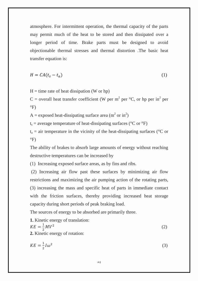
atmosphere. For intermittent operation, the thermal capacity of the parts
may permit much of the heat to be stored and then dissipated over a
longer period of time. Brake parts must be designed to avoid
objectionable thermal stresses and thermal distortion .The basic heat
transfer equation is:
(1)
H = time rate of heat dissipation (W or hp)
C = overall heat transfer coefficient (W per m2 per °C, or hp per in
2 per
°F)
A = exposed heat-dissipating surface area (m2 or in
2)
ts = average temperature of heat-dissipating surfaces (°C or °F)
ta = air temperature in the vicinity of the heat-dissipating surfaces (°C or
°F)
The ability of brakes to absorb large amounts of energy without reaching
destructive temperatures can be increased by
(1) Increasing exposed surface areas, as by fins and ribs.
(2) Increasing air flow past these surfaces by minimizing air flow
restrictions and maximizing the air pumping action of the rotating parts,
(3) increasing the mass and specific heat of parts in immediate contact
with the friction surfaces, thereby providing increased heat storage
capacity during short periods of peak braking load.
The sources of energy to be absorbed are primarily three.
1. Kinetic energy of translation:
(2)
2. Kinetic energy of rotation:
(3)
38
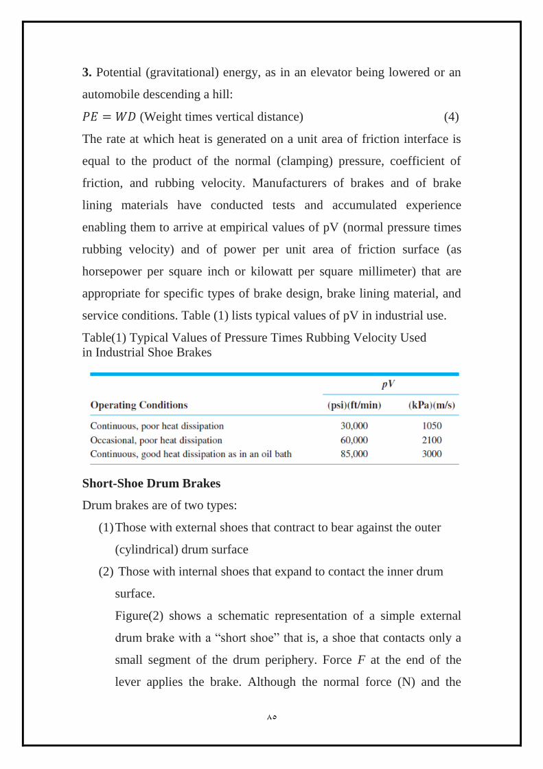
3. Potential (gravitational) energy, as in an elevator being lowered or an
automobile descending a hill:
(Weight times vertical distance) (4)
The rate at which heat is generated on a unit area of friction interface is
equal to the product of the normal (clamping) pressure, coefficient of
friction, and rubbing velocity. Manufacturers of brakes and of brake
lining materials have conducted tests and accumulated experience
enabling them to arrive at empirical values of pV (normal pressure times
rubbing velocity) and of power per unit area of friction surface (as
horsepower per square inch or kilowatt per square millimeter) that are
appropriate for specific types of brake design, brake lining material, and
service conditions. Table (1) lists typical values of pV in industrial use.
Table(1) Typical Values of Pressure Times Rubbing Velocity Used
in Industrial Shoe Brakes
Short-Shoe Drum Brakes
Drum brakes are of two types:
(1) Those with external shoes that contract to bear against the outer
(cylindrical) drum surface
(2) Those with internal shoes that expand to contact the inner drum
surface.
Figure(2) shows a schematic representation of a simple external
drum brake with a “short shoe” that is, a shoe that contacts only a
small segment of the drum periphery. Force F at the end of the
lever applies the brake. Although the normal force (N) and the
38
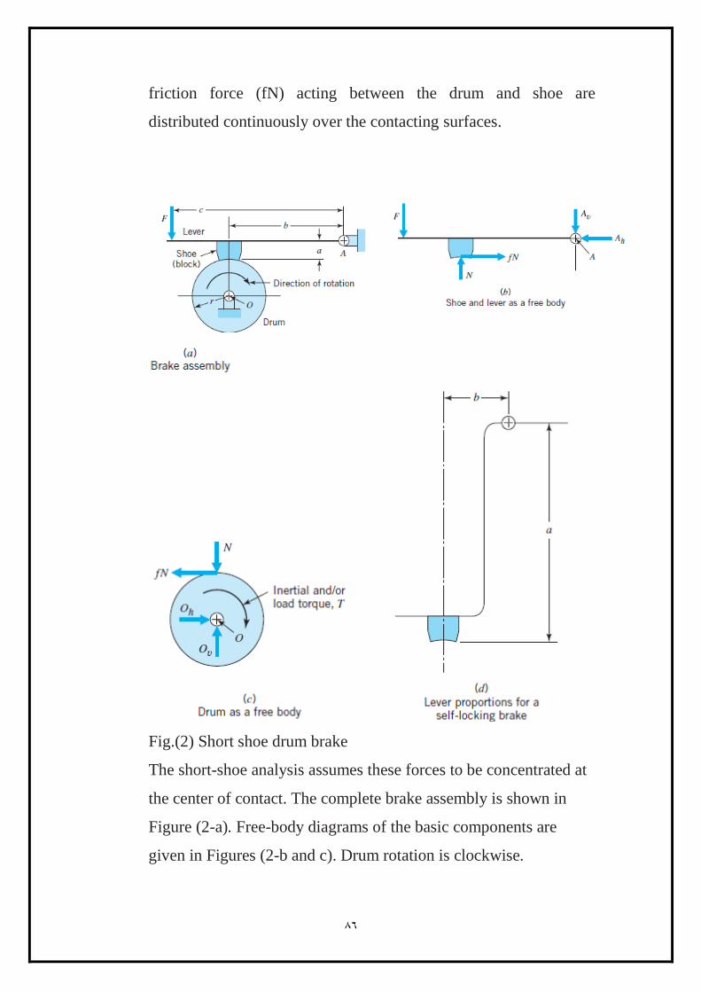
friction force (fN) acting between the drum and shoe are
distributed continuously over the contacting surfaces.
Fig.(2) Short shoe drum brake
The short-shoe analysis assumes these forces to be concentrated at
the center of contact. The complete brake assembly is shown in
Figure (2-a). Free-body diagrams of the basic components are
given in Figures (2-b and c). Drum rotation is clockwise.
38
Taking moments about pivot A for the shoe and lever assembly, we
have :
(5)
From summation of moments about O for the drum,
(6)
Solving equation (5) for N and substituting in equation (6) gives
(7)
(self energizing) (8)
Torque T is the inertial and load torque required for equilibrium, and it is
numerically equal to the friction torque developed by the brake.
Equation (8) is labeled “self-energizing” because the moment of the
friction force ( fNa) assists the applied force (F) in applying the brake.
For counter-clockwise drum rotation, the direction of the friction force
would be reversed. This would cause it to oppose the application of the
brake, making the brake self-de energizing. The derivation of the
equation for the de energizing brake is the same as for the self-energizing
brake, except that the signs of the friction force terms are reversed:
(self- de energizing) (9)
Returning now to self-energized braking (clockwise drum rotation), note
that the brake is self-locking if the denominator of Eq. (8) is zero or
negative. Thus, for self-locking,
(10)
For example, if f = 0.3, self-locking (for clockwise drum rotation) is
obtained if b 0.3a. This is illustrated in Figure (2-d). A self-locking
brake requires only that the shoe be brought in contact with the drum
(with F = 0) for the drum to be “locked” against rotation in one direction.
Because the brake in Figure (2)has only one shoe (block), the entire force
exerted on the drum by the shoe must be reacted by the shaft bearings.
Partly for this reason, two opposing shoes are almost always used.

33
Ex:
The two-shoe external drum brake shown in Figure(3) has shoes 80 mm
wide that contact 90° of drum surface. For a coefficient of friction of 0.20
and an allowable contact pressure of 400 kN per square meter of
projected area, estimate:
(a) The maximum lever force F that can be used, (b) the resulting braking
torque.
(c) The radial load imposed on the shaft bearings.
Assume short-shoe drum brake.
(a)

38
Fig.(3) Two shoe drum brake
The free body diagram for all the components of the two shoe drum brake
can be shown in figures (3-b) to (3-f).
1- The force analysis begins with floating lever 5 because it receives
the applied force F.
Taking moments about O25 establishes
2- For the link 4 ,
but in opposite direction.
89
3- Link (3)
On the left shoe (link 3), the applied force is H43 (which is equal and
opposite to H34). The short-shoe analysis assumes that the normal and
friction forces applied by drum 6 act at the center of the shoe as shown.
The normal force is H63 and the friction force is H63 multiplied by the
given friction coefficient of 0.2.
Summation of moments about O13 gives:
0.08)=0
Or
Normal and friction forces H62 and V62 acting on shoe 2 are determined in
the same manner. The moment equation has an additional term because
both horizontal and vertical forces are applied by link 2:
89
Or
Horizontal and vertical forces applied to drum 6 are equal and opposite to
corresponding forces applied to the shoes. If as assumed the drum angular
acceleration is zero, the load torque T (which tends to continue the
clockwise direction of rotation) is equal to (2.11F + 1.41F) times the
drum radius, or 0.880F N.m.
Forces applied at fixed pivot O16 are H16 = 3.46F and V16 = 0.70F.
The allowable value of F is governed by the allowable pressure on the
self-energized shoe. The projected area of the shoe is the 80-mm width
multiplied by the chord length subtended by a 90° arc of the 250-mm-
radius drum:
A = 80[2(250 sin 45°)] = 28,284 mm2
The normal pressure on shoe 3 is
Equating this to the allowable value of pmax = 0.40 N/mm2 gives
The corresponding brake torque is
From figure (3-f)
The braking torque can be calculated as:
Or
The resultant radial load transmitted to the bearing is
√ F=3.53F=3791N
89
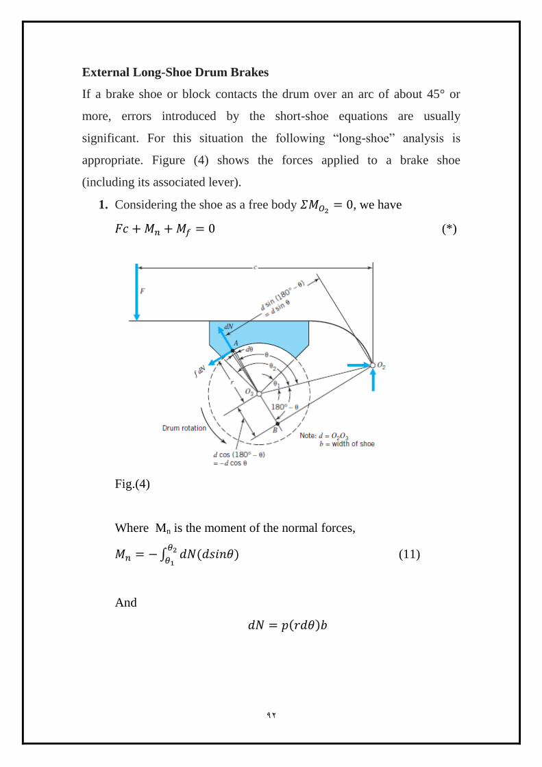
External Long-Shoe Drum Brakes
If a brake shoe or block contacts the drum over an arc of about 45° or
more, errors introduced by the short-shoe equations are usually
significant. For this situation the following “long-shoe” analysis is
appropriate. Figure (4) shows the forces applied to a brake shoe
(including its associated lever).
1. Considering the shoe as a free body , we have
(*)
Fig.(4)
Where Mn is the moment of the normal forces,
∫
(11)
And
88
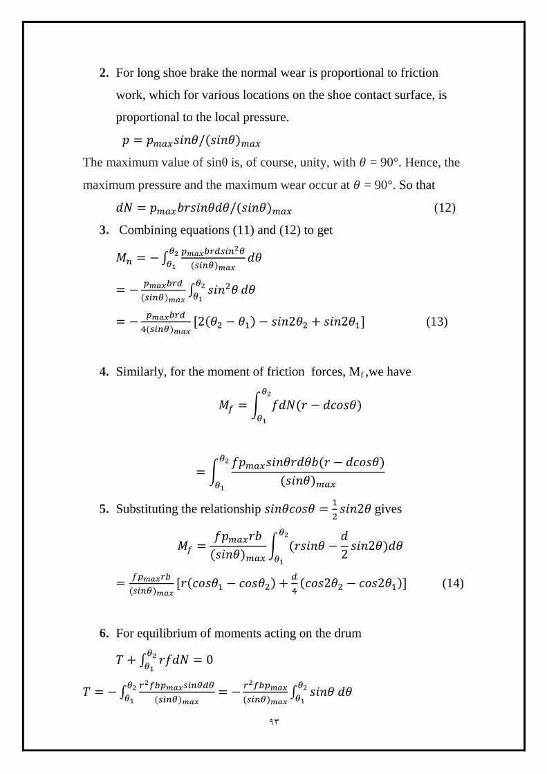
2. For long shoe brake the normal wear is proportional to friction
work, which for various locations on the shoe contact surface, is
proportional to the local pressure.
The maximum value of sinθ is, of course, unity, with = 90°. Hence, the
maximum pressure and the maximum wear occur at = 90°. So that
(12)
3. Combining equations (11) and (12) to get
∫
∫
(13)
4. Similarly, for the moment of friction forces, Mf ,we have
∫
∫
5. Substituting the relationship
gives
∫
(14)
6. For equilibrium of moments acting on the drum
∫
∫
∫

88
(15)
7. Reaction forces at O2 and O3 can readily be obtained from
horizontal and vertical force equilibrium equations.
With reference to Eq.(*),
it is evident that a self-energizing brake is self- locking if Mf ≥ Mn. It is
often desired to make a brake shoe strongly self-energizing while staying
safely away from a self-locking condition. This can be done by designing
the brake so that the value of Mf , as calculated using a value of (f) that is
25 to 50 percent greater than the true value, is equal to the value of Mn.
88
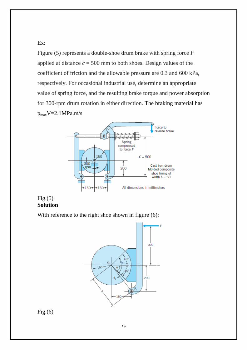
Ex:
Figure (5) represents a double-shoe drum brake with spring force F
applied at distance c = 500 mm to both shoes. Design values of the
coefficient of friction and the allowable pressure are 0.3 and 600 kPa,
respectively. For occasional industrial use, determine an appropriate
value of spring force, and the resulting brake torque and power absorption
for 300-rpm drum rotation in either direction. The braking material has
pmaxV=2.1MPa.m/s
Fig.(5)
Solution
With reference to the right shoe shown in figure (6):
Fig.(6)
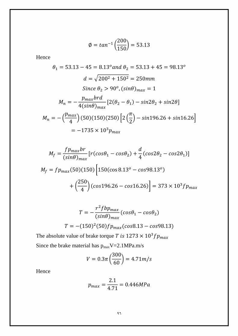
88
(
)
Hence
√
(
) * (
) +
[
(
) ]
The absolute value of brake torque
Since the brake material has pmaxV=2.1MPa.m/s
(
)
Hence
88
Or
(Spring force)
The appropriate spring force was determined above on the basis of
allowable pressure on the right shoe, which proved to be mildly self-
energizing. This same spring force will produce a lower value of pmax on
the left shoe. Applying the following equation to the left shoe, the only
change is the sign of the friction moment term:
The total brake torque is the brake torque of the right plus the brake
torque of the left shoe
Since
Hence
The power can be calculated as
Band Brakes
Perhaps the simplest of the many braking devices is the band brake,
shown in Figure (7). The band itself is usually made of steel, lined with a
woven friction material for flexibility. For the clockwise drum rotation
shown, friction forces acting on the band serve to increase P1 and

83
decrease P2. With the drum and band portion above the cutting plane
Figure (7) considered as a free body, brake torque T is equal to
Fig.(7) Band brake
(16)
With the lever and band portions below the cutting plane considered as a
free body, the applied lever force F is
(17)
Figure (8) shows the forces acting on an element of the band. For small
angle d .
Fig.(8) Element of band brake
(18)
(
) (19)

88
Also by definition
(20)
where p is the local contact pressure between drum and band. Substituting
Eq.(19) into Eq.(18) gives:
(21)
Or
(22)
Band force P varies from P1 to P2 over the band portion between = 0
and = . Hence, integrating Eq.(22) over the length of contact gives
∫
∫
(23)
(24)
Fig.(9)
(25)

999
The maximum normal pressure pmax acting on the band occurs at
where P = P1.
and
Hence
(26)
The brake in Figure(7) is self-energized for clockwise drum rotation.
Greater self-energizing action can be obtained by attaching the previously
fixed end of the band to the lever at the opposite side of the pivot, as
shown in Figure (9). The tensile force of this attachment now serves to
assist in the application of the brake. Note also that distance s must be
less than distance a so that rotating the lever with force F tightens the end
of the band attached at distance a more than it loosens the end attached at
distance s. A study of the motion and forces involved at the two band
attachment points shows why the name differential band brake is
appropriate. For a differential band brake, Eq.(17) is replaced by
(27)
Ex:
A differential band brake shown in Figure (10) uses a woven lining
having a design value of f = 0.20. Dimensions are b = 80 mm, r = 250
mm, c = 700 mm, a = 150 mm, s = 35 mm, and = 240°. Find
(a) The brake torque if the maximum lining pressure is 0.5 MPa.
(b) The corresponding actuating force F.
(c) The values of dimension s that would cause the brake to be self-
locking.

999
Fig.(10) Differential band break
Solution
From equation (26)
From equation (25)
From equation (16)
From equation (27)
From equation (27)
For F=0,
The brake self-locked for (f=0.2)

999
Supplementary Problems(brakes)
(Q1) Consider the following dimensions for the short-shoe drum brake of
Figure (11) radius of drum = 5 in., shoe width = 2 in., shoe length = 4 in.,
c = 10 in., b = 6 in., a = 1.5 in., p = 100 psi, and f = 0.3. Determine the
value of the actuating force F.
Fig.(11)
998
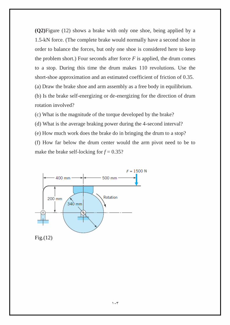
(Q2)Figure (12) shows a brake with only one shoe, being applied by a
1.5-kN force. (The complete brake would normally have a second shoe in
order to balance the forces, but only one shoe is considered here to keep
the problem short.) Four seconds after force F is applied, the drum comes
to a stop. During this time the drum makes 110 revolutions. Use the
short-shoe approximation and an estimated coefficient of friction of 0.35.
(a) Draw the brake shoe and arm assembly as a free body in equilibrium.
(b) Is the brake self-energizing or de-energizing for the direction of drum
rotation involved?
(c) What is the magnitude of the torque developed by the brake?
(d) What is the average braking power during the 4-second interval?
(e) How much work does the brake do in bringing the drum to a stop?
(f) How far below the drum center would the arm pivot need to be to
make the brake self-locking for f = 0.35?
Fig.(12)

998
998
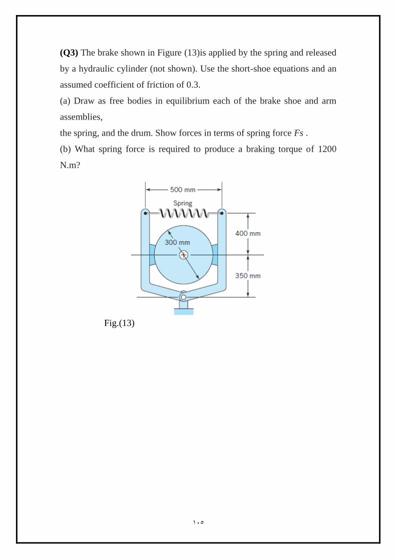
(Q3) The brake shown in Figure (13)is applied by the spring and released
by a hydraulic cylinder (not shown). Use the short-shoe equations and an
assumed coefficient of friction of 0.3.
(a) Draw as free bodies in equilibrium each of the brake shoe and arm
assemblies,
the spring, and the drum. Show forces in terms of spring force Fs .
(b) What spring force is required to produce a braking torque of 1200
N.m?
Fig.(13)
998
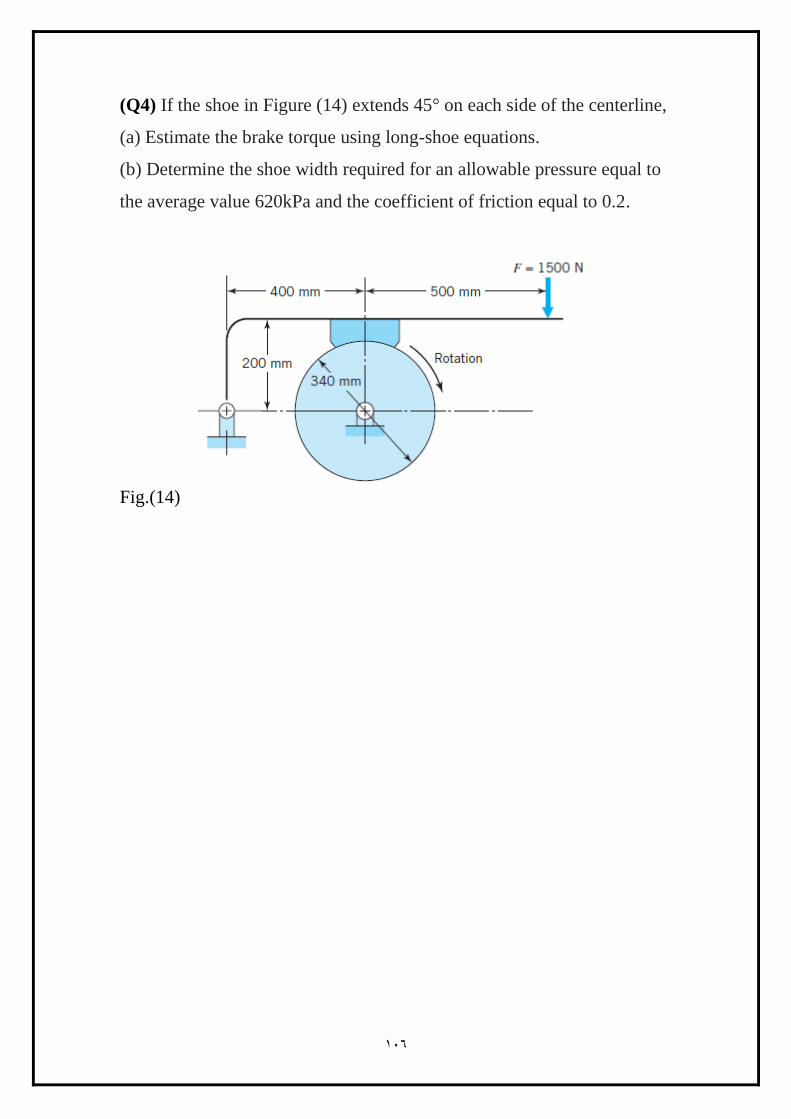
(Q4) If the shoe in Figure (14) extends 45° on each side of the centerline,
(a) Estimate the brake torque using long-shoe equations.
(b) Determine the shoe width required for an allowable pressure equal to
the average value 620kPa and the coefficient of friction equal to 0.2.
Fig.(14)

998
(Q5) The brake shown in Fig. (15) is 300 mm in diameter and is actuated
by a mechanism that exerts the same force F on each shoe. The shoes are
identical and have a face width of 32 mm. The lining is a molded asbestos
having a coefficient of friction of 0.32 and a pressure limitation of 1000
kPa. Estimate the maximum
(a) Actuating force F.
(b) Braking capacity.
.
Fig.(15)
Solution:
(a) The right-hand shoe is self-energizing, and so the force F is found on
the basis that the maximum pressure will occur on this shoe. Here θ1 = 0◦,
θ2 = 126◦, θa = 90◦, and
(sin θ)max = 1. Also,
√
993
[
]
Or
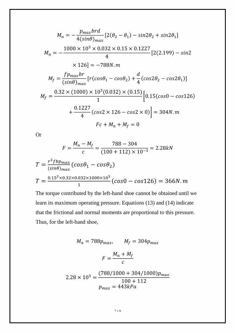
The torque contributed by the left-hand shoe cannot be obtained until we
learn its maximum operating pressure. Equations (13) and (14) indicate
that the frictional and normal moments are proportional to this pressure.
Thus, for the left-hand shoe,
998
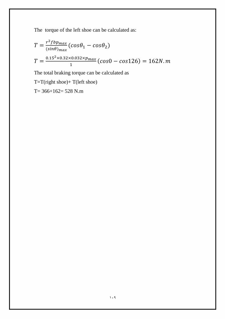
The torque of the left shoe can be calculated as:
The total braking torque can be calculated as
T=T(right shoe)+ T(left shoe)
T= 366+162= 528 N.m