Brake Engineering Technical Bulletins 2014
38
TECHNICAL BULLETIN 2014
-
Upload
brake-engineering -
Category
Documents
-
view
220 -
download
3
description
Â
Transcript of Brake Engineering Technical Bulletins 2014

Brake EngineeringRedwither Road, Wrexham Industrial Estate, Wrexham LL13 9RDT +44 (0) 1978 667800 F +44 (0) 1978 667801 E [email protected]
Technical BulleTin 2014

For over 30 years Brake Engineering has produced precision-engineered brake discs and drums using the very latest in CNC technology with ever improving levels of unrivalled quality. Coupled with an excellent worldwide sourcing strategy, the company now offer a flexible range that not only has an enviable reputation as the major benchmark in the aftermarket but also enables the product group to remain competitive in the global marketplace.The Brake Engineering brake discs and drums programme is noted as being the front-runner in range coverage
throughout the aftermarket and this is undoubtedly one of the key contributors to the success, development and progression of this product group today.The company’s market leading disc and drum catalogue is widely recognised as being number one for the aftermarket user with excellent range development as the main focus.A consistent new parts introduction programme ensures that the company continue to achieve market leader status striving towards 100% vehicle parc coverage.
www.brake-eng.com
Brake Discs & Drums
Technical Document Reference Product
2 Inlet risk assessment - Ford, Land Rover, LDV BE014 Brake Calipers
Audi rear caliper identification BE015 Brake Calipers
CA2287 - Citroen C5 Oldcore return guide BE016 Brake Calipers
Leading & Trailing caliper guide BE017 Brake Calipers
Citroen C5 front caliper identification BE018 Brake Calipers
Core acceptance guide BE019 Brake Calipers
Handbrake caliper fitting procedure BE021 Brake Calipers
Handbrake caliper reset procedure BE022 Brake Calipers
LDV front caliper identification BE023 Brake Calipers
Standard mechanical caliper check BE010 Brake Calipers
Volvo S40/V40 real caliper identification BE025 Brake Calipers
Brake disc wear guide BE011 Brake Discs
Loose wheel retaining bolts BE012 Brake Discs
Brake disc with intergrated wheel bearing BE037 Brake Discs
Bedding the brake pads BE013 Brake Pads
Fitting Kits BE032 Brake Pads
Concentric slave cylinder fitting instructions BE028 Hydraulics
Dangers of conductivity type brake fluid testers BE029 Hydraulics
Dot 4 material safety data sheet BE026 Hydraulics
Ford Mondeo master cylinder warning BE027 Hydraulics
Block exemption regulator BE036 General
Technical BulleTin 2014

TechnicalBulletin
2 inlet calipers - Risk assessment
www.brake-eng.com Technical Helpline:+44 (0) 1978 667811
TRW UK Aftermarket,Redwither Road, Wrexham Industrial Estate, Wrexham LL13 9RD http://www.brake-eng.com/Tech-Talk/
Vehicles: Ford Transit - Land Rover - LDV
Calipers concerned: CA14/R - CA327/R - CA394/R - CA462/R - CA752/R - CA1065/R - CA1219/R - CA1587/R
Warning: Do not block these inlets
The above calipers are all 2 inlet fitting and must NOT be fitted to 1 inlet applications. By blocking one of the inlets braking efficiency will be considerably reduced, as only two of the four pistons will be working.
BACK TO InDEx

Audi Rear Caliper Identification - Audi A4
www.brake-eng.com Technical Helpline:+44 (0) 1978 667811
TRW UK Aftermarket,Redwither Road, Wrexham Industrial Estate, Wrexham LL13 9RD http://www.brake-eng.com/Tech-Talk/
TechnicalBulletin
CA1498 / CA1498RInlet: 10mm (Std)Piston: 38mmDisc: SolidCasting No:LH-6142 RH-6143
Std = Standard inlet pipe fittingBan = Banjo inlet pipe fitting
Inlet next to bleed screw
CA1514 / CA1514RInlet: 10mm (Std)Piston: 38mmDisc: SolidCasting No:LH-4061 RH-4062
Inlet 90 degrees to bleed screw
CA1987 / CA1987RInlet: 12mm (Ban)Piston: 38mmDisc: SolidCasting No:LH-877 RH-878
Inlet opposite to bleed screw
CA2441 / CA2441RInlet: 12mm (Ban)Piston: 43mmDisc: VentedCasting No:LH-542 RH-543
Inlet opposite to bleed screw
CA2447 / CA2447RInlet: 12mm (Ban)Piston: 38mmDisc: SolidCasting No:LH-737 RH-738
Inlet next to bleed screw
CA2583 / CA2583RInlet: 10mm (Std)Piston: 43mmDisc: VentedCasting No:LH-542 RH-543
Inlet opposite to bleed screw
Page 1 of 3
BACK TO InDEx

Audi Rear Caliper Identification - Audi A6
www.brake-eng.com Technical Helpline:+44 (0) 1978 667811
TRW UK Aftermarket,Redwither Road, Wrexham Industrial Estate, Wrexham LL13 9RD http://www.brake-eng.com/Tech-Talk/
TechnicalBulletin
CA1195 / CA1195RInlet: 10mm (Std)Piston: 38mmDisc: SolidCasting No:LH-2624 RH-2625
Std = Standard inlet pipe fittingBan = Banjo inlet pipe fitting
Inlet next to bleed screw
CA1237 / CA1237RInlet: 10mm (Std)Piston: 43mmDisc: VentedCasting No:LH-32322392 RH-32322393
Inlet next to bleed screw
CA1474 / CA1474RInlet: 10mm (Std)Piston: 38mmDisc: SolidCasting No:LH-4060 RH-4061
Inlet opposite to bleed screw
CA2026 / CA2026RInlet: 12mm (Ban)Piston: 38mmDisc: SolidCasting No:LH-046 RH-047
Inlet opposite to bleed screw
CA2441 / CA2441RInlet: 12mm (Ban)Piston: 43mmDisc: VentedCasting No:LH-542 RH-543
Inlet opposite to bleed screw
Page 2 of 3
BACK TO InDEx

Audi Rear Caliper Identification - Audi A8
www.brake-eng.com Technical Helpline:+44 (0) 1978 667811
TRW UK Aftermarket,Redwither Road, Wrexham Industrial Estate, Wrexham LL13 9RD http://www.brake-eng.com/Tech-Talk/
TechnicalBulletin
CA1195 / CA1195RInlet: 10mm (Std)Piston: 38mmDisc: SolidCasting No:LH-2624 RH-2625
Std = Standard inlet pipe fittingBan = Banjo inlet pipe fitting
Inlet next to bleed screw
CA1510 / CA1510RInlet: 10mm (Std)Piston: 43mmDisc: VentedCasting No:LH-4921 RH-4922
Inlet next to bleed screw
CA2315 / CA2315RInlet: 10mm (Std)Piston: 38mmDisc: SolidCasting No:N/A
Inlet opposite to bleed screw
CA2328 / CA2328RInlet: 12mm (Ban)Piston: 43mmDisc: VentedCasting No:LH-559 RH-560
Inlet next to bleed screw
Page 3 of 3
BACK TO InDEx

TechnicalBulletin
Citroen C5Oldcore Return Guide
www.brake-eng.com Technical Helpline:+44 (0) 1978 667811
TRW UK Aftermarket,Redwither Road, Wrexham Industrial Estate, Wrexham LL13 9RD http://www.brake-eng.com/Tech-Talk/
CA2287 & CA2287RPiston Diameter: 32 mm
Pad Gap: 49.5 mm
Casting Numbers: 9629086010
Beware of broken pad pin holes !
Beware of damaged pad pin holes when returning CA2287 & CA2287R, all old units returned like this will be
rejected for surcharge credit
BACK TO InDEx

TechnicalBulletin
Leading & Trailing Calipers
www.brake-eng.com Technical Helpline:+44 (0) 1978 667811
TRW UK Aftermarket,Redwither Road, Wrexham Industrial Estate, Wrexham LL13 9RD http://www.brake-eng.com/Tech-Talk/
Brake
Trailing Caliper
The caliper is mounted on the rear of the disc
Leading Caliper
The caliper is mounted on the front of the disc
Please note: On some applications it is possible to have eiither a leading ot trailing caliper positions using the same caliper
For example: Caliper N/S Caliper O/S Make Model Year Axle MAN LD/TRCA1243 CA1243R Ford Mondeo 03/93>10/00 F ATE LDCA1243R CA1243 Ford Scorpio 01/95>07/98 F ATE TR
BACK TO InDEx

TechnicalBulletin
Citroen C5 Front Calipers
www.brake-eng.com Technical Helpline:+44 (0) 1978 667811
TRW UK Aftermarket,Redwither Road, Wrexham Industrial Estate, Wrexham LL13 9RD http://www.brake-eng.com/Tech-Talk/
There are 2 options of front calipers for 2.0 & 2.2 HDi
CA2115 & CA2115RDisc Diameter: 283 mm
Disc Thickness: 26 mm
Casting Numbers: 1083 (LH) 1084 (RH)
Mounting Holes (Centre to Centre): 175 mm
CA2116 & CA2116RDisc Diameter: 288 mm
Disc Thickness: 28 mm
Casting Numbers: 1086 (LH) 1087 (RH)
Mounting Holes (Centre to Centre): 188 mm
BACK TO InDEx

At Brake Engineering we have strict guidelines when it comes to core returns.Please follow these acceptance criteria when returning old core.Core will not be eligible for refund if it has any of these faults.
Caliper Core Acceptance CriteriaBleed ScrewBleed Screw should not be excessively damaged
xx PP
Bracket ArmBracket arm should not be damaged
xx PP
Brake DiscCasting should not be worn due to brake disc
xx PP
Carrier GuideCarrier guide should not be damaged
xx PP
Entry PortEntry port should not be snapped or damaged
xx PP
Handbrake CableHandbrake cable guide should not be damaged
xx PP
Mounting FeetMounting feet should not be damaged
xx PP
Pad Pin HolesPad pin holes should not be broken
xx PP
xx PP
Scan this QR code, and take this poster wherever you go
TRW UK AftermarketRedwither Road, Wrexham Ind Estate,Wrexham LL13 9RDTechnical Helpline: +44 (0)1978 667811www.brake-eng.com/Tech-Talk/
Corroded End FacesAluminium split calipers end faces should not be corroded
BBE019 - Core Acceptance Guide_Layout 1 14/06/2013 16:26 Page 1
BACK TO InDEx

Hand Brake Caliper Fitting Procedure
www.brake-eng.com Technical Helpline:+44 (0) 1978 667811
TRW UK Aftermarket,Redwither Road, Wrexham Industrial Estate, Wrexham LL13 9RD http://www.brake-eng.com/Tech-Talk/
DO NOT operate handbrake lever before fitting to the vehicle. The unit has been preset at the factory, if you have to,go to the last paragraph.
Adjust the pad gap on the brake caliper using the adjusting procedures below to ensure there is no more than 1mmclearance between both brake pads and disc.
ADJUSTING PAD GAP BRAKE CALIPER TYPE A (LUCAS, AKEBONO, BENDIX)
Using an Allen key or pair of long nose pliers in the dedicated slots on the front of the piston.
Rotate piston anti-clockwise to move the piston ‘out’.
If the piston is rotated in it must be rotated at least half a turn out to ensure the internal mechanism has reset beforeyou proceed any further.
Fit the brake caliper and brake pads but do not fit the handbrake cable.
Fully bleed the hydraulic system.
Fit the handbrake cable and adjust to remove any slack. Make sure that the gap between the lever-to-stop does notexceed 1mm.
ADJUSTING PAD GAP BRAKE CALIPER TYPE B (ATE & NBK)
Remove plug on rear caliper.
Using 4mm Allen key adjust piston, do not use excessive force as this can cause damage.
Rotate Allen key clockwise to move the piston ‘out’.
If the piston is wound in at any stage it must be wound out again by at least half a turn of the adjuster to ensure theinternal mechanism has reset before you proceed any further.
Fit the brake caliper and brake pads but do not fit the handbrake cable.
Fully bleed the hydraulic system.
Fit the handbrake cable and adjust to remove any slack. Make sure that the gap between thelever-to-stop does not exceed 1mm.
To reset the handbrake mechanism if the lever has been operated before fitting then the pistonshould be turned ‘in’ using the above methods. When the piston is fully ‘IN’ then the piston should beturned ‘OUT’ half to 1 turn. The handbrake mechanism is now set.
CAUTION: DO NOT OVER ADJUST CALIPER OR SPLINES WILL STRIP ON ADJUSTER
TechnicalBulletin
BACK TO InDEx

Hand Brake Caliper Reset Procedure
www.brake-eng.com Technical Helpline:+44 (0) 1978 667811
TRW UK Aftermarket,Redwither Road, Wrexham Industrial Estate, Wrexham LL13 9RD http://www.brake-eng.com/Tech-Talk/
If the hand brake lever is moved prior to fitting and adjustment to the vehicle.It will throw the automatic hand brake adjustment out. If this happens, the hand brake mechanism will have to be reset by the following methods.
FOR TYPE A CALIPERS (SLOTS IN PISTON TYPE)
If the caliper has not been fitted to the vehicle.
Using a suitable tool, locate the slots in the piston and turn it in clockwise (Take care! later calipers can have a left hand thread) Until it stops. Turn the piston back out between ¼ and ½ turn. This resets the mechanism back to the lever. Continue to turn the piston out until you reach the neccessary adjustment of 1 mm clearance between the disc and the pads.
If there is alocating peg on the back of the pads, you will need to line this peg up with a slot in the piston. The easiest way is to mount the pads in the caliper and then slide the whole assembly over the disc. Bleed the caliper through, then operate the pedal a few times to centralise the assembly. Finally connect the hand brake cable and adjust accordingly.If the caliper has been fitted to the vehicle and the adjustment has been lost.
You will need to start the reset procedure by first taking off the hand brake cable, then clamping off the hydraulic flexi pipe, then open up the bleed screw. Then follow the above procedure.
FOR TYPE B CALIPERS (THREADED PLUG ON BACK OF CALIPER)
Remove the threaded plug to reveal an allen headed bolt type adjuster. Using a 4 mm allen key, turn it anti-clockwise to wind the piston in until it stops. Turn the allen key clockwise to wind the piston back out between ¼ and ½ turn.Then follow the above instructions for (Type A) caliper, but using the allen keyto turn the piston.
DON’T FORGET TO REPLACE THE THREADED PLUG.
TechnicalBulletin
BACK TO InDEx

LDV Front Caliper Identification
www.brake-eng.com Technical Helpline:+44 (0) 1978 667811
TRW UK Aftermarket,Redwither Road, Wrexham Industrial Estate, Wrexham LL13 9RD http://www.brake-eng.com/Tech-Talk/
TechnicalBulletin
CA462 / CA462R
Discs: SolidInlet: TwinPad Pin Holes: 5mm
CA778 / CA778R
Discs: VentedInlet: SinglePad Pin Holes: 5mm
CA846 / CA846R
Discs: SolidInlet: SinglePad Pin Holes: 5mm
CA937 / CA937R
Discs: SolidInlet: SinglePad Pin Holes: 7mm
CA1065 / CA1065R
Discs: VentedInlet: TwinPad Pin Holes: 5mm
CA1216 / CA1216R
Discs: VentedInlet: SinglePad Pin Holes: 7mm
Once these criteria have been matched, we then need to know whether the calipers are leading or trailing on the vehicle.
BACK TO InDEx

BrakeE N G I N E E R I N G
“Tech-Talk“
What is a standard mechanical Caliper check?
The standard check of a Caliper should consist of the mechanical function check ofall the Caliper parts.
As a second part this test should include the visual inspection (leaking, crackingand wear of the parts)
Sticking Brake Pads as a example (see picture) are often the reason for noise occurrence, judder and / or overheated Brakes.
Guide Pins have to move smoothly.
Wheel hubs and centre rings of Disc should be free of corrosion and without damage otherwise judder could occur
Handbrake cable moves free
www.brake-eng.com
TRW UK Aftermarket, Redwither Road, Wrexham Industrial Estate, Wrexham LL13 9RD http://www.brake-eng.com/Tech-Talk/
TechnicalBulletin
Technical Helpline:+44 (0) 1978 667811
PP
xxGuide Pins
BACK TO InDEx

Volvo S40 / V40 Rear Caliper Identification
www.brake-eng.com Technical Helpline:+44 (0) 1978 667811
TRW UK Aftermarket,Redwither Road, Wrexham Industrial Estate, Wrexham LL13 9RD http://www.brake-eng.com/Tech-Talk/
TechnicalBulletin
CA1746 / CA1746R
Without external hand brake return spring
CA1746 / CA1746R
With external hand brake return spring
There are 2 options of rear calipers for the Volvo S40/V40, these calipers are not interchangeable.
BACK TO InDEx

BrakeE N G I N E E R I N G
“Tech-Talk“
Brake Disc Wear
Blue coloured brake disc
The cause of the blue colour is continuous braking during driving downhill or hard brakingfrom a high speed.The blue colour has no direct impact to the brake efficiency. If there are cracks or deformations, change as an axle set.
www.brake-eng.com
TRW UK Aftermarket, Redwither Road, Wrexham Industrial Estate, Wrexham LL13 9RD http://www.brake-eng.com/Tech-Talk/
TechnicalBulletin
Technical Helpline:+44 (0) 1978 667811
Cracked disc
Continuous braking during downhill driving or hard braking from a high speed causes extreme temperature differences. This could lead to cracks. Brake discs have tobe changed as an axle set.
Page 1 of 2 u
BACK TO InDEx

BrakeE N G I N E E R I N G
“Tech-Talk“
Brake Disc Wear
Ridged disc
The surface of the disc should be smooth
Slight grooves are acceptable
A heavily scored disc must be replaced
www.brake-eng.com
TRW UK Aftermarket, Redwither Road, Wrexham Industrial Estate, Wrexham LL13 9RD http://www.brake-eng.com/Tech-Talk/
TechnicalBulletin
Technical Helpline:+44 (0) 1978 667811
Corroded disc
Any corrosion of a brake disc might be for thefollowing reasons:
Malfunction of hydraulic parts•LCRV / PCRV problem•Soft use of braking system•Low car mileage•
Page 2 of 2
BACK TO InDEx

BrakeE N G I N E E R I N G
“Tech-Talk“
Loose Wheel Retaining Bolts
The reason identified for this problem is corrosion betweenthe disc and hub mounting faces.
www.brake-eng.com
TRW UK Aftermarket, Redwither Road, Wrexham Industrial Estate, Wrexham LL13 9RD http://www.brake-eng.com/Tech-Talk/
TechnicalBulletin
Technical Helpline:+44 (0) 1978 667811
Corroded Material
Step 1:Remove the brake disc
Step 2:Scrub hub face with a wire brush, removing all corroded material
Step 3:Sand down the hub face, removing any remaining corrosion
Step 4:Measure the contact area of hub andwheel
The hub couldbe out of shapeby using an impact wrench.
Check the hubwith a ruler.
Step 5: Re-install retaining bolts and replace disc onto the clean hub, PP
BACK TO InDEx

Brake disc with integrated wheel bearing
www.brake-eng.com Technical Helpline:+44 (0) 1978 667811
TRW UK Aftermarket,Redwither Road, Wrexham Industrial Estate, Wrexham LL13 9RD http://www.brake-eng.com/Tech-Talk/
TechnicalBulletin
Page 1 of 5
Never compromise on safetyOur bearing discs with integrated bearing are manufactured to the highest standards. Never compromise on safety, fit Brake Engineering.
Advantages:
• Complete kit, including all the necessary replacement parts for mounting brake disc with integrated wheel bearing, washer, ASB®-magnetic encoder (Active Sensor Bearing) nut and cover.
• Simple, quick and precise mounting.• No special tools necessary to press the wheel bearing.• Avoids wrong mounting. Assembling loose components to one unit often causes problems
with the fitting, aligning and the clearance.• Perfect fitting to avoid complaints about vibrations and noise, caused by the brakes.• 100% identical to the original product. Therefore, it meets the high demands of the car
manufacturers.
Beware of imitations!
There are also some copies on the market which can be dangerous for the safety of the driver. Intensive tests have been performed and here are the main findings:
• The integrated bearings do not follow the OE-specifications, in particular for what concerns their lifespan and quality. Reduced lifespan can lead to premature failure of the brake and even loss of the wheel!
• The magnetic encoder (the patented ASB®-sensor ring) doesn’t have the necessary OE-quality. Some of them do not even have the same number of poles! This causes almost every time a malfunction in the ABS-and ESP-system.
DamagedMagneticPole
NormalMagneticPole
PX
BACK TO InDEx

Brake disc with integrated wheel bearing
www.brake-eng.com Technical Helpline:+44 (0) 1978 667811
TRW UK Aftermarket,Redwither Road, Wrexham Industrial Estate, Wrexham LL13 9RD http://www.brake-eng.com/Tech-Talk/
TechnicalBulletin
Page 2 of 5
Why risk your safety?
A premium product is not only the guarantee of quality and durability, it is also the best way to ensure safety reliability of your vehicle.You wouldn’t make any economies with your life. So why risk you life by buying counterfeit products?
Mounting Tips
Brake discs are safety parts. Install the part carefully and always work in a clean working place. Although mounting a brake disc with integrated bearing is simple, a few points you have to pay attention to.
1. The nut and cover always have to be replaced. If the old nut and cover are used, the risk exists that these can get loose again.
2. Clean the axle journal.3. Clean the ASB®-sensor and check with the ASB®-test card.4. Install the brake disc with integrated bearing without force on the axle journal (loose fit) and
don’t forget to degrease.5. Make sure that the disc doesn’t tilt. The inner ring can easily be pushed. Tools are not nec-
essary and should not be used.6. Place the washer (if present) in the right position and turn the new nut to the stop with the
hand. The brake disc has to be turned continuously in the meantime to guarantee an exact centering of the bearing components. An impact drive should not be used.
7. Pull the axle nut to the correct torque. Take into account the torque specifications of the car manufacturer. The torque should be exact. The vehicle should not stand on the wheels and also here, the brake disc has to be turned continuously in the meantime.
8. Don’t expose the wheel bearing to magnetic fields. Otherwise, the ASB®-sensor ring may be damaged.
9. Grease the contact surface of the nut cap before mounting. Use a wooden hammer to avoid deformation.
BACK TO InDEx

Brake disc with integrated wheel bearing
www.brake-eng.com Technical Helpline:+44 (0) 1978 667811
TRW UK Aftermarket,Redwither Road, Wrexham Industrial Estate, Wrexham LL13 9RD http://www.brake-eng.com/Tech-Talk/
TechnicalBulletin
Page 3 of 5
Remarks
The ASB ®-Magnetic encoder ring is not sold separately in the aftermarket because this ring cannot be removed or replaced without damaging. Using a screwdriver as a “removal tool”, only a small part of the ring can be lifted. This can result in a deformation of the ring. Using a hammer to mount the magnetic ring can cause visible and invisible damage. A system failure can appear quickly as soon as the magnetic ring is mounted on the new brake disc. This can lead to a failure in the ABS-system and the consequences can be fatal.
The European Law forbids the mounting and use of brake discs with uneven wear on the same axle. Therefore, both brake discs should be replaced at the same time.
BACK TO InDEx

Brake disc with integrated wheel bearing
www.brake-eng.com Technical Helpline:+44 (0) 1978 667811
TRW UK Aftermarket,Redwither Road, Wrexham Industrial Estate, Wrexham LL13 9RD http://www.brake-eng.com/Tech-Talk/
TechnicalBulletin
Page 4 of 5
The advantages of an ASB®-bearing
The ASB®-bearing measures the rotation and speed of the wheel and sends the data to the considered systems in the vehicle. The active sensor sends a digital signal to the vehicle computer and has many advantages, among which:
• The possibility of measuring wheel speed down to zero.• Saving in space and weight.• Simplified assembly of wheel.• Standardisation of the components.
BACK TO InDEx

Brake disc with integrated wheel bearing
www.brake-eng.com Technical Helpline:+44 (0) 1978 667811
TRW UK Aftermarket,Redwither Road, Wrexham Industrial Estate, Wrexham LL13 9RD http://www.brake-eng.com/Tech-Talk/
TechnicalBulletin
Page 5 of 5
Part No Make Model Start Year
End Year
Axle Bearing/ABS Info
OE Numbers
DI956714S CITROEN / PEUGEOT C3 / C3 PICASSO 2001 2009 R +Bearing +ABS 424919, 424932
DI956396S CITROEN / PEUGEOT C4 / 307 2003 2006 R +Bearing -ABS 4246Z9
DI956700S CITROEN / PEUGEOT C4 / 307 2001 2006 R +Bearing -ABS 4246Z9, 424934
DI956856S CITROEN / PEUGEOT C4 / 308 2007 R +Bearing +ABS 424965, 424966
DI956618S NISSAN / RENAULT / VAUXHALL PRIMASTAR / TRAFIC / VIVARO
2001 2008 R +Bearing +ABS 7711130076
DI956936S RENAULT CLIO 1991 1997 R +Bearing +ABS 7701207611
DI956425S RENAULT CLIO / GRAND MODUS / MEGANE / MODUS / TWINGO / WIND
2002 2011 R +Bearing -ABS 7701207823
DI956648S RENAULT CLIO / GRAND MODUS / MEGANE / MODUS / TWINGO / WIND
2002 2012 R +Bearing +ABS 8867108106
DI956937S RENAULT CLIO / MEGANE 1996 2005 R +Bearing +ABS 7701204901
DI956940S RENAULT ESPACE / GRAND ESPACE / VEL SATIS
2002 R +Bearing +ABS 8200018407, 7701206924, 8200663193
DI956672S RENAULT ESPACE / GRANDE ESPACE / VEL SATIS
2002 2006 R +Bearing +ABS 8200244108
DI956532S RENAULT GRAND SCENIC / MEGANE / SCENIC
2003 2009 R +Bearing +ABS 7701207898
DI956971S RENAULT GRAND SCENIC / SCENIC 2009 R +Bearing +ABS 432000007R
DI956713S RENAULT GRAND SCENIC / SCENIC (LWB)
2003 2009 R +Bearing +ABS 7701208230
DI956924S RENAULT KANGOO 2008 R +Bearing +ABS 8200381148
DI956264S RENAULT LAGUNA 1998 2008 R +Bearing +ABS 7701472838, 7701713008, 8200367094
DI956402S RENAULT LAGUNA 2001 2008 R +Bearing -ABS 7701713008, 7701472838, 8200367094
DI956728 RENAULT LAGUNA 2008 2012 R +Bearing +ABS 402020005R
DI956923S RENAULT LAGUNA 2007 R +Bearing +ABS 402020003R
DI956889 RENAULT MEGANE 2008 R +Bearing +ABS 432001539R
DI956906S RENAULT MEGANE 2005 2009 R +Bearing +ABS 7701208850
DI956979 RENAULT MEGANE 2005 R +Bearing +ABS 8200266043
DI956136S RENAULT MEGANE / SCENIC 1997 2003 R +Bearing +ABS 7701206328
BACK TO InDEx

BrakeE N G I N E E R I N G
“Tech-Talk“
Bedding the Brake PadsNew brake pads must be bedded. Thesurface area of the disc and pad must beeven for optimal braking performance, thisis why it is important during the bedding inprocess to avoid heavy braking, to allowthe pad and disc surface to even-up witheach other.
www.brake-eng.com
TRW UK Aftermarket, Redwither Road, Wrexham Industrial Estate, Wrexham LL13 9RD http://www.brake-eng.com/Tech-Talk/
TechnicalBulletin
Technical Helpline:+44 (0) 1978 667811
Bring the brake pads in their operatingposition by pressing the brake pedaldown (half of normal pedal travel) severaltimes until there is resistance.
Check the brake fluid level, and top up to‘Max’ mark if necessary.
Note:In order to bed the brake pads to the brake disc and ensureperformance and endurance, the vehicle user must be instructed to avoid heavy braking or sustained periods with the brakes applied, for the first 200 miles after installing new pads.
0Miles
200Miles
Brake P
ad
Brake P
ad
Brake D
isc
DiscSurface
BACK TO InDEx
TechnicalBulletin
Fitting Kits
www.brake-eng.com Technical Helpline:+44 (0) 1978 667811
TRW UK Aftermarket,Redwither Road, Wrexham Industrial Estate, Wrexham LL13 9RD http://www.brake-eng.com/Tech-Talk/
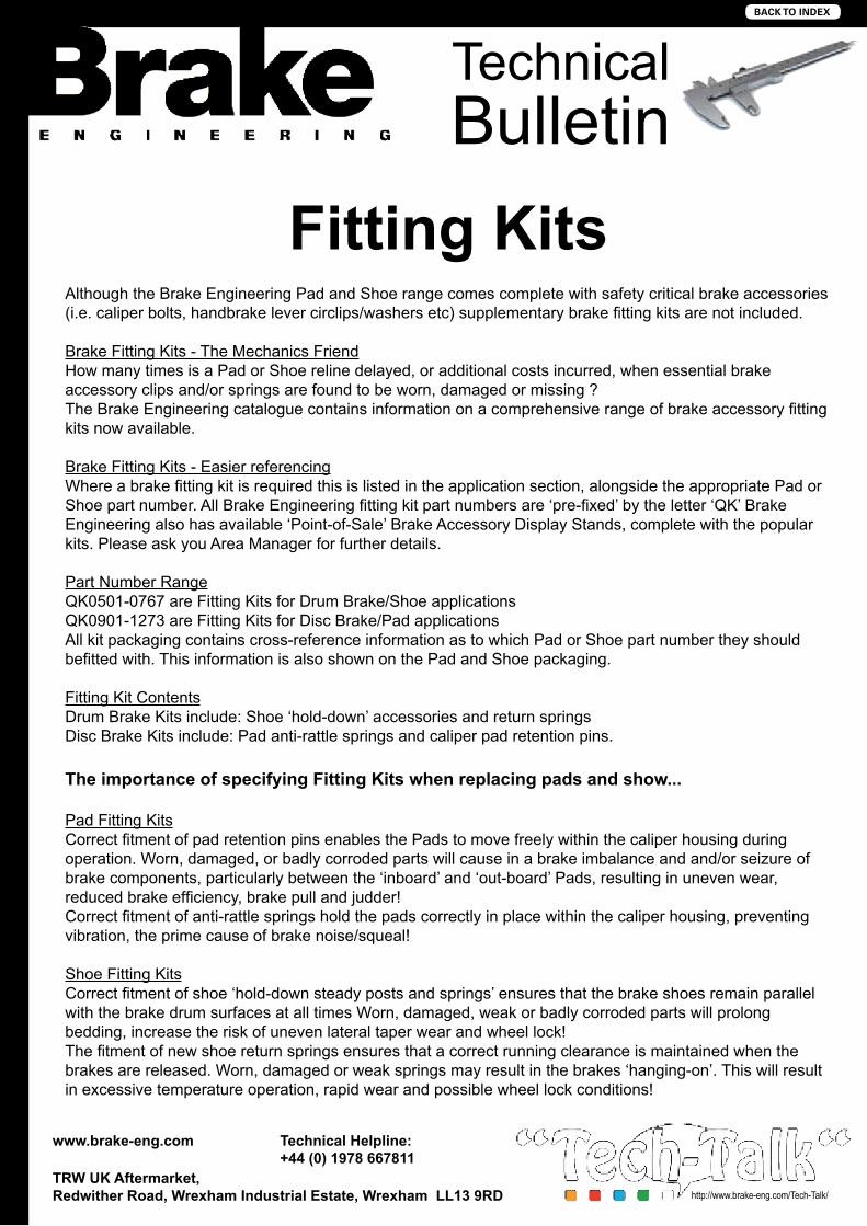
Although the Brake Engineering Pad and Shoe range comes complete with safety critical brake accessories (i.e. caliper bolts, handbrake lever circlips/washers etc) supplementary brake fitting kits are not included.
Brake Fitting Kits - The Mechanics FriendHow many times is a Pad or Shoe reline delayed, or additional costs incurred, when essential brake accessory clips and/or springs are found to be worn, damaged or missing ?The Brake Engineering catalogue contains information on a comprehensive range of brake accessory fitting kits now available.
Brake Fitting Kits - Easier referencingWhere a brake fitting kit is required this is listed in the application section, alongside the appropriate Pad or Shoe part number. All Brake Engineering fitting kit part numbers are ‘pre-fixed’ by the letter ‘QK’ Brake Engineering also has available ‘Point-of-Sale’ Brake Accessory Display Stands, complete with the popular kits. Please ask you Area Manager for further details.
Part Number RangeQK0501-0767 are Fitting Kits for Drum Brake/Shoe applicationsQK0901-1273 are Fitting Kits for Disc Brake/Pad applicationsAll kit packaging contains cross-reference information as to which Pad or Shoe part number they should befitted with. This information is also shown on the Pad and Shoe packaging.
Fitting Kit ContentsDrum Brake Kits include: Shoe ‘hold-down’ accessories and return springsDisc Brake Kits include: Pad anti-rattle springs and caliper pad retention pins.
The importance of specifying Fitting Kits when replacing pads and show...
Pad Fitting KitsCorrect fitment of pad retention pins enables the Pads to move freely within the caliper housing during operation. Worn, damaged, or badly corroded parts will cause in a brake imbalance and and/or seizure of brake components, particularly between the ‘inboard’ and ‘out-board’ Pads, resulting in uneven wear, reduced brake efficiency, brake pull and judder!Correct fitment of anti-rattle springs hold the pads correctly in place within the caliper housing, preventing vibration, the prime cause of brake noise/squeal!
Shoe Fitting KitsCorrect fitment of shoe ‘hold-down steady posts and springs’ ensures that the brake shoes remain parallel with the brake drum surfaces at all times Worn, damaged, weak or badly corroded parts will prolong bedding, increase the risk of uneven lateral taper wear and wheel lock!The fitment of new shoe return springs ensures that a correct running clearance is maintained when thebrakes are released. Worn, damaged or weak springs may result in the brakes ‘hanging-on’. This will result in excessive temperature operation, rapid wear and possible wheel lock conditions!
BACK TO InDEx

TechnicalBulletin
Concentric Slave Cylinder Fitting Instructions
www.brake-eng.com Technical Helpline:+44 (0) 1978 667811
TRW UK Aftermarket,Redwither Road, Wrexham Industrial Estate, Wrexham LL13 9RD http://www.brake-eng.com/Tech-Talk/
SERVICE INFORMATION01/2010 rev. 07/2010rev. 07/2010
Fitting instructions for the Concentric Slave Cylinder (CSC)The concentric slave cylinder (CSC) is subjected to just as much natural wear as the clutch or flywheeland should be replaced every time the clutch is changed.
There are a few important things to consider during installation in order to preserve the functionalityand service life of the components.
Critical points when fitting the CSC:
• Do not repeatedly pump the clutch pedal when bleeding; depress just once and wait for hydraulicsystem to stabilize before pumping again. (Risk of over pressure inside CSC)
• Do not use any lubricants or cleaning agents as they may damage the gaskets or entire cylinder.• A high level of cleanliness is critical at all times.• Only use brake fluid approved by the car manufacturer.• Gaskets, seals and the connection areas must be totally clean.• Clean the transmission input shaft and ensure that there is no damage or excessive wear on shaft seal
area.• Make sure the slave cylinder is installed flat against the transmission-mounting surface • Fit the slave cylinder fixing bolts and tighten per the vehicle manufacturer requirements.
Always read the specifications of the vehicle manufacturer! !
FOR FURTHER INFORMATION:[email protected]
Subject to technical changes©2010 LPR s.r.l.S-info_01/2010 – rev. 07/2010
cy g g p q• Flush the connecting hose through with clean fluid before assembly to prevent contamination of the
new cylinder.• Fill the reservoir with an approved DOT 3 or 4 brake fluid.• NEVER bleed the CSC if the clutch and flywheel are not yet assembled.• Make sure the CSC is not tilted during installation. Failure may lead to damage of the fixing lugs or
reduced service life.• Do not over tighten bleed screw.• Bleed screw torque for Plastic housing (3 to 5 Nm) - for Aluminum housing (15 to 20 Nm)
THE ENTIRE CLUTCH MECHANISM SHOULD BE CHANGED WHEN FITTING ANEW CONCENTRIC SLAVE CYLINDER,
PAGE 1 of 4
DAMAGE CAUSED BY INCORRECT OR POOR FITTING PRACTISE WILL NOT BE HONOURED UNDER WARRANTY.! !
Dispose of the waste oil and used parts according to proper country and/or state disposal regulations
CSC001 Brake Engineering Technical Support
Concentric Slave Cylinder
Fitting Instructions
01978 6
67811
www.brake-eng.com
Page 1 of 4
Page 1 of 4
BACK TO InDEx

TechnicalBulletin
Concentric Slave Cylinder Fitting Instructions
www.brake-eng.com Technical Helpline:+44 (0) 1978 667811
TRW UK Aftermarket,Redwither Road, Wrexham Industrial Estate, Wrexham LL13 9RD http://www.brake-eng.com/Tech-Talk/
SERVICE INFORMATION01/2010 rev. 07/2010rev. 07/2010
2 - OVER STROKERepeated pumping of the clutch during bleeding can cause the clutch slave to over stroke This will
ASSEMBLY ERRORS1 - FRICTION PLATE WRONG WAY AROUND
If the friction plate is assembled the wrong wayaround, it will damage the retaining ring and causeleakage.
Retaining ring damage
ASSY
ASSY ����
����
FOR FURTHER INFORMATION:[email protected]
Subject to technical changes©2010 LPR s.r.l.S-info_01/2010 – rev. 07/2010
PAGE 2 of 6
Repeated pumping of the clutch during bleeding can cause the clutch slave to over stroke. This willresult in the damage of the retaining ring or primary seal as the sliding sleeve can slip out of the bore.The main seal will also be damaged if it attempts are made to re-fit it.
Typical Over-stroke seal damageOver-stroke retaining ring damage
CSC001 Brake Engineering Technical Support
Concentric Slave Cylinder
Fitting Instructions
01978 6
67811
Page 2 of 4
Page 2 of 4
BACK TO InDEx

TechnicalBulletin
Concentric Slave Cylinder Fitting Instructions
www.brake-eng.com Technical Helpline:+44 (0) 1978 667811
TRW UK Aftermarket,Redwither Road, Wrexham Industrial Estate, Wrexham LL13 9RD http://www.brake-eng.com/Tech-Talk/
SERVICE INFORMATION01/2010 rev. 07/2010rev. 07/2010
3 - AXIAL AND ANGULAR SHAFT/ENGINE MISALIGNMENT
The transmission shaft must be perfectly aligned during fitment, as excessive axial or angularmisalignment will stress the primary seal causing a reduction in the life of the unit.
If there is excessive axial or angular misalignment, when the transmission shaft rotates it can generatemineral oil mist which can contaminate the primary seal leading to failure of the cylinder.
4 – INCORRECT FLUID USE
The clutch hydraulic system MUST only be filled with the manufacturers recommended fluid.Never use mineral oil
1: parallel offset ; 2: Angular offset
Possible causes of misalignment are:• Centering between engine and gear box is notcorrect (deformation, heavy dirt or wear);• Other parts (e.g. grounding straps) trappedbetween engine and gear box during installation);• Flange bolts loose or not properly tightened;• Close-tolerance sleeves or pins missing /damaged;• Pilot bearing in the flywheel is absent or badly worn;• Clutch bell housing warped due to unevenly or over torqued fixing bolts• Clutch bell housing deformed due to dropping or striking hard when fitting.
FOR FURTHER INFORMATION:[email protected]
Subject to technical changes©2010 LPR s.r.l.S-info_01/2010 – rev. 07/2010
PAGE 3 of 6
Never use mineral oil.
!If the wrong hydraulic fluid is used, the seals in the system will be damaged.
In systems which are combined with the brake system, seals in the brake system may arise.POTENTIAL FOR ACCIDENTS!
Volume change - contact with mineral fluid
STD dimension
seal after contact
with mineraloil
CSC001 Brake Engineering Technical Support
Concentric Slave Cylinder
Fitting Instructions
01978 6
67811
Page 3 of 4
Page 3 of 4
BACK TO InDEx

TechnicalBulletin
Concentric Slave Cylinder Fitting Instructions
www.brake-eng.com Technical Helpline:+44 (0) 1978 667811
TRW UK Aftermarket,Redwither Road, Wrexham Industrial Estate, Wrexham LL13 9RD http://www.brake-eng.com/Tech-Talk/
SERVICE INFORMATION01/2010 rev. 07/2010rev. 07/2010
5 - BLEEDING ERROR – OVER PRESSURE
DO NOT USE POWER ASSISTED BLEEDING DEVICES ON THE CLUTCH SYSTEM
Use of these systems can over pressurize the concentric slave cylinder. If this occurs, it will causepermanent damage to the cylinder and it will need to be replaced!Manual bleeding should be carried out using the following process:1. Depress clutch pedal2. Open bleed valve3. Keep clutch pedal depressed until fluid appears – Do not release!4. Close bleed valve5. Release clutch pedal slowly6. Do not repeatedly pump the clutch
The clutch bleeding cycle must be repeated 20 to 25 times to guarantee complete bleeding. Top upthe level of the fluid in the reservoir between the cycles. The level of the fluid must not drop below theminimum mark on the reservoir during bleeding!
6 - CONTAMINATION – GEAR SHAFTEnsure that all contamination is removed during the disassembly and re-assembly processes. Any
FOR FURTHER INFORMATION:[email protected]
Subject to technical changes©2010 LPR s.r.l.S-info_01/2010 – rev. 07/2010
PAGE 4 of 6
debris or swarf can contaminate the main seal and cause leakage..
Aluminum swarf causing leakage from gear side
!
CSC001 Brake Engineering Technical Support
Concentric Slave Cylinder
Fitting Instructions
01978 6
67811
Page 4 of 4
Page 4 of 4
BACK TO InDEx

TechnicalBulletin
Dangers of Conductivity Type Brake Fluid Testers
www.brake-eng.com Technical Helpline:+44 (0) 1978 667811
TRW UK Aftermarket,Redwither Road, Wrexham Industrial Estate, Wrexham LL13 9RD http://www.brake-eng.com/Tech-Talk/
HYD001 Brake Engineering Technical Support
Dangers of conductivity
type brake fluid testers
01978 6
67811
www.brake-eng.com
Electronic devices to test automotive brake fluid when in service are becoming increasingly popular. Correctly
designed and used, they can make a real contribution to road safety, while providing profit opportunities for
garages.
However, customers should be aware that these testers are not all of the same design and some are very
much better than others. We are aware of many incidents where electronic brake fluid testers have incorrectly
failed new product straight out of a bottle, while under different circumstances passing product as acceptable
which had become dangerous for use.
In our experience any brake fluid tester which does not actually heat the fluid is likely to give misleading or
even dangerous results. Such testers will estimate the water content electronically by measuring the
conductivity (or occasionally the capacitance) of the fluid, which in theory increases as water is absorbed.
The tester then converts this measurement to supposed boiling point and indicates the result commonly as a
display of green, yellow or red lights, depending on the conductivity.
Unfortunately, this measurement principle is fatally flawed as the
conductivity of new brake fluids varies substantially, from not only
between DOT 3, DOT 4 or DOT 5.1 types but also from formulation
to formulations within a DOT grade depending on the additives used.
This means that unless a conductivity tester is calibrated on one
manufacturer’s product and then used for that product only, it is likely
to give very inaccurate results.
In contrast to this type of equipment testers are available which
actually heat a sample of the fluid to establish the boiling point,
thereby getting away from the problem of varying conductivities. In
our experience these provide the best balance of performance and economy currently available. Even so
caution is needed, careful handling and regular calibration being required if results are to be reliable.
In cases where customers require totally accurate water contents or boiling points, it is recommended that
they return samples to Brake Engineering so that laboratory tests can be conducted to ensure that the fluid
meets the required standards using industry standard techniques such as the well known Karl Fischer
method for water content.
For further information please contact our
Technical Department on (01978) 667811
Example of a
conductivity type
Brake Fluid Tester
BACK TO InDEx

Dot 4 Brake FluidMaterial Safety Data Sheet
www.brake-eng.com Technical Helpline:+44 (0) 1978 667811
TRW UK Aftermarket,Redwither Road, Wrexham Industrial Estate, Wrexham LL13 9RD http://www.brake-eng.com/Tech-Talk/
TechnicalBulletin
Page 1 of 5
1. IDENTIFICATION1.1 Product NameBrake Engineering DOT 4 Brake Fluid 2. COMPOSITION/INFORMATION ON INGREDIENTS2.1 GeneralBlend of polyglycol ethers, glycol ether borate esters and polyglycols with added corrosion and oxidation inhibitors.
3. HAZARDS IDENTIFICATION3.1 Physical HazardsNot significant.3.2 Health Hazards R 36: Irritating to eyes. Mildly irritating to skin. When ingested it may be absorbed and cause renal damageat high dosage.3.3 Environmental Hazards : Low4.FIRST AID MEASURES4.1 Inhalation - Remove to fresh air. If recovery is not rapid, seek medical attention.4.2 Skin Contact - Remove contaminated clothing. Wash affected skin with soap and water.If irritation persists seek medical at-tention.4.3 Eye Contact - Flush eye with water for at least 10 mins. If irritation persists seek medical attention.4.4 Ingestion - Obtain medical advice immediately.If patient is fully conscious,wash out mouth with water and give plenty of water to drink.Induce vomiting only under medical supervision.4.5 Note to Physicians - Medical personnel seeking to administer first aid are referred to the services of the Poisons Information Centre,who can advise in such instances. There is no specific antidote and treatment of over exposure should be directed at control of symptoms and the patient’s clinical condition.5.FIRE FIGHTING MEASURES5.1 Suitable Extinguishing MediaAlcohol resistant foam,dry powder or water (fog or fine spray).5.2 Unsuitable Extinguishing MediaWater jets (although these may be used to cool adjacent containers).5.3 Exposure HazardsNo special risk – combustion products may contain harmful or irritant fumes.5.4 Special Protective EquipmentIn extreme conditions self-contained breathing apparatus should be worn.6. ACCIDENTAL RELEASE MEASURES6.1 Personal PrecautionsAvoid contact with eyes, skin, and clothing. When cleaning up large spillages, suitable protective clothing should be worn including eye protection and impervious gloves.
Hazardous Ingredients Einecs / Eilincs No.
CAS-Number Concentration in %
Hazard Classification
Risk Phrases
Butyl tri glycol 205-592-6 143-22-6 >20 Xi R36Di ethylene glycol 203-872-2 111-46-6 <25 Xn R22Methyl di glycol 203-906-6 111-77-3 <5 Xn R63
BACK TO InDEx

Dot 4 Brake FluidMaterial Safety Data Sheet
www.brake-eng.com Technical Helpline:+44 (0) 1978 667811
TRW UK Aftermarket,Redwither Road, Wrexham Industrial Estate, Wrexham LL13 9RD http://www.brake-eng.com/Tech-Talk/
TechnicalBulletin
Page 2 of 5
6.2 Environmental PrecautionPrevent from entering drains, ditches or rivers. If this happens inform relevant authorities. Prevent gross contamination of soil.6.3 Methods for Cleaning UpContain spillage using sand or earth. Remove all material to a suitable container for subsequent disposal. Label Salvage Container appropriately. Flush contaminated area with plenty of water.7. HANDLING AND STORAGE7.1 StorageSuitable bulk storage vessels are mild/stainless steel tanks fitted with a dry air breathing system or tight head steel drums. Do not store in lined tanks or drums. Brake fluid absorbs water from the atmosphere - always keep containers tightly closed. Avoid contamination with any other substances and in particular with mineral oils which are incompatible.7.2 HandlingNo specific handling precautions are necessary.7.3 Specific Use Users are referred to the Specification SAE J1707 “Service Maintenance of Brake Fluids”8. EXPOSURE CONTROLS/PERSONAL PROTECTION8.1 Exposure ControlsNo official TLV/OEL figures available for the entire preparation. However,8 h TWA limits of 100 mg/m3 vapour or 10 mg/m3 particulate should be adhered to and this will ensure no limits for ingredients are exceeded.Due to the low vapour pressure of the preparation,vapour is not generally a problem at ambient temperature. Handling equipment should minimise the formation of mists.8.2 Respiratory ProtectionNo specific precautions at ambient temperature. If fluid is being heated or atomised, use suitable engineering control measures.8.3 Hand ProtectionWear suitable impervious gloves to avoid prolonged or repeated contact. Polyethylene natural or butyl rubber and PVC are suitable materials.8.4 Eye ProtectionWear close-fitting goggles where there is a risk of splashing. Eye baths should be provided at locations where accidental expo-sure may occur.8.5 Skin ProtectionWhere significant exposure is possible wear impervious body covering.It is recommended that showers are provided at locationswhere accidental exposure may occur.8.6 Environmental Exposure ControlsNo special measures required.
BACK TO InDEx

Dot 4 Brake FluidMaterial Safety Data Sheet
www.brake-eng.com Technical Helpline:+44 (0) 1978 667811
TRW UK Aftermarket,Redwither Road, Wrexham Industrial Estate, Wrexham LL13 9RD http://www.brake-eng.com/Tech-Talk/
TechnicalBulletin
Page 3 of 5
Physical Chemical Properties Tested in accordance with9.1 - Appearance Clear liquid - Usually colourless to
amber although some grades of brake fluid may be highly dyed.
9.2 - Odour Bland9.3 - pH 7.0 to 10.50 SAE J 17039.4 - Boiling point >205 Deg.C. SAE J 17039.5 - Melting point <-50 Deg.C. SAE J 17039.6 - Flash point >80 Deg.C. DOT 3, 90 Deg.C. DOT 4 IP 359.7 - Auto ignition temp. >300 Deg.C. ASTM D 2869.8 - Flammability limits in the air Not established9.9 - Density @ 20°C 1.010 - 1.070 g/ml9.10 - Solubility In water: miscible in any ratio
In ethanol: miscible in any ratio9.11 - Partition Coefficient n-Octanol/Water (log POW)
<2.0 (all main ingredients) OECD 117
9.12 - Viscosity @ 20°C Approx. 5-10 cSt ASTM D 4459.13 - Vapour pressure 20°C < 2 milibars Reid9.14 - Vapour Density Not established9.15 - Evaporation Rate Negligible
10. STABILITY AND REACTIVITY10.1 Conditions to AvoidProduct is stable under normal conditions.Glycol Ethers can form peroxide on storage – do not distil to dryness.10.2 Materials to AvoidStrong oxidising agents. For user safety, brake fluid should never be contaminated with any other substance.10.3 Hazardous Decomposition ProductsNone known.
9. PHYSICAL AND CHEMICAL PROPERTIES
BACK TO InDEx

Dot 4 Brake FluidMaterial Safety Data Sheet
www.brake-eng.com Technical Helpline:+44 (0) 1978 667811
TRW UK Aftermarket,Redwither Road, Wrexham Industrial Estate, Wrexham LL13 9RD http://www.brake-eng.com/Tech-Talk/
TechnicalBulletin
Page 4 of 5
11. TOXICOLOGICAL INFORMATION (comments may be based on analogy with similar products).11.1 Eye ContactProduct has an irritating effect on the eye. (Test Method OECD 405).11.2 Skin ContactNot classified as irritant (Test Method OECD 404) although some sensitive individuals may be affected.Repeated contact may de-fat the skin and cause dermatitis.Product does not contain any known sensitisers. Acute percutaneous toxicity is low LD50 (sk) Rat = > 2000 mg/kg.11.3 IngestionProduct is of relatively low acute oral toxicity – however,if any significant amount is ingested there is a risk of renal damage which in extreme cases could lead to kidney failure,coma and death.LD50 (oral) Rat = > 5000 mg/kg. Sparse experience indicates lethal dose in man could be considerably less.11.4 InhalationUnlikely to be hazardous by inhalation at ambient due to low vapour pressure.If product is inhaled at elevated temperatures or as an aerosol it may irritate respiratory tract and may cause systemic effects similar to ingestion (see above).11.5 Chronic or Long Term ToxicityGeneral – There are no reports of long term adverse affects in man.Carcinogenicity Not known to be carcinogenic.Mutagenicity Not known to be mutagenic.Reproductive ToxicityMajor ingredients have not been shown to cause significant fertility or development problems at levels which are not themselvestoxic to the animal concerned.One minor ingredient – Methyl di glycol – has been shown to affect foetus development in some studies and is classified as R63 – possible risk of harm to the unborn child.
12. ECOLOGICAL INFORMATION12.1 Ecotoxicity – Product is of low acute ecotoxicity.Fish 96h LC50 = > 100 mg/l (Oncorhynchus Mykiss)Daphnia 48h EC50 = Not Determined but expected to be virtually non toxic.Algae 72h EC50 = Not Determined but expected to be virtually non toxic.12.2 MobilitySoluble in water and will partition to aqueous phase. Volatilisation from water to air not expected. Mobile in soil until degraded.12.3 Persistence/DegradabilityProduct is inherently biodegradable and is expected to be readily biodegradable.OECD 302B (Zahn Wellans/EMPA) = 100% elimination at 21 days.If admitted into adapted biological water treatment plants,no adverse effects on the degrading action of the live sludge are expected.12.4 Bioaccumulative PotentialNot expected to bioaccumulate. Log POW for all main ingredients = < 2.0
BACK TO InDEx

Dot 4 Brake FluidMaterial Safety Data Sheet
www.brake-eng.com Technical Helpline:+44 (0) 1978 667811
TRW UK Aftermarket,Redwither Road, Wrexham Industrial Estate, Wrexham LL13 9RD http://www.brake-eng.com/Tech-Talk/
TechnicalBulletin
Page 5 of 5
13. DISPOSAL CONSIDERATIONS13.1 Disposal DangersNot significant. As for spillages - avoid liquid entering drains, rivers etc.13.2 Disposal MethodsControlled incineration or recycling is recommended.13.3 RegulationsDispose of in accordance with local and national regulations. In the E.U. used brake fluids are covered by the Hazardous Waste Directive (91/689/EEC) while the Waste Framework Directive (75/442/EEC) also applies.
14. TRANSPORT INFORMATION14.1 - UK / EU Regulations Not classified14.2 - UN No./Class None14.3 - ADR/RID Not classified14.4 - IMO/IMDG Not classified as hazardous14.5 - Marine Pollutant No14.6 - IATA/IACO Class Not classified
15. REGULATORY INFORMATION15.1 - E.U. Classification (U.K. CHIP 3)
Risk PhrasesR36 - Irritating to eyes.
Safety PhrasesS2 - Keep out of reach of children.S26 (Modified) - In case of contact with eyes, rinse immediately with water for 10 mins. If irritation persists seek medical advice.S46 - If swallowed seek medical advice immediately and show the container or label
15.2 Restrictions on use or ExposureTo be in accord with local and national regulations. In the U.K. this would include the HSWA and COSHH.
16. OTHER INFORMATION16.1 Legal DisclaimerThe information contained herein is based on the present knowledge and experience of Brake engineering. It in no way constitutes the users own assessment of work place risk as required by other Health and Safety legislation.Brake engineering does not, by supplying this information, guarantee or warrant any specific properties or qualities of goods supplied.It is the responsibility of the purchaser to determine whether the goods ordered are fit for any purpose for which they may be required. This information is provided subject to Brake engineering’s Conditions of Sale, and in particular Conditions 9 and 14 thereof.
BACK TO InDEx

TechnicalBulletin
Ford Mondeo Master Cylinder Warning
www.brake-eng.com Technical Helpline:+44 (0) 1978 667811
TRW UK Aftermarket,Redwither Road, Wrexham Industrial Estate, Wrexham LL13 9RD http://www.brake-eng.com/Tech-Talk/
Part Number: MC1455BEVehicle: Ford Mondeo (with ABS)Year: 02/93 > 02/96
This master cylinder is 98mm long when measured from face of mounting flange to the end by the last outlet. Some models have a longer cylinder of appoximately 120mm in length (MC1043BE). MC1455BE is not to be confused or fitted in place of this longer cylinder.
IF FITTED INCORRECTLY, IT WILL ALTER PEDAL TRAVEL AND CAUSE THE BRAKES TO LOCK UP.
98mm
BACK TO InDEx
Block Exemption Regulation
www.brake-eng.com Technical Helpline:+44 (0) 1978 667811
TRW UK Aftermarket,Redwither Road, Wrexham Industrial Estate, Wrexham LL13 9RD http://www.brake-eng.com/Tech-Talk/
Brake Engineering is an original equipment manufacturer of brake components for various UK & European vehicle manufacturers. Where products produced and distributed by Brake Engineering are not manufactured specifically for the vehicle manufacturers these products are produced to the same stringent quality standards.
Brake Engineering manufacturers all products under the control of ISO9001:2008 quality system, all parts supplied by Brake Engineering are compliant with EEC Commission Regulation 461/2010 which came into force on 1st June 2010.
Brake Engineering prides its self in offering the most comprehensive range of quality braking components to the independent aftermarket. All parts sold are a direct replacement for those fitted to the vehicle by the vehicle manufacturer and in some applications exceed the performance of the original part.
Our range of asbestos free brake pads and shoes are also manufactured to the same stringent quality standards and, comply with the latest ECE Regulation R90 directive where applicable (vehicles registered on or after 1999).
BACK TO InDEx

Brake EngineeringRedwither Road, Wrexham Industrial Estate, Wrexham LL13 9RDT +44 (0) 1978 667800 F +44 (0) 1978 667801 E [email protected]