Brain Book ENGINE TORQUE GEARBOX OIL … contribution to this project is the assembling of ... needs...
30
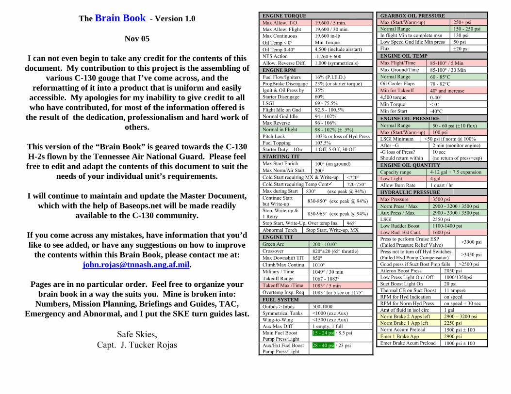
The Brain Book - Version 1.0 Nov 05 I can not even begin to take any credit for the contents of this document. My contribution to this project is the assembling of various C-130 gouge that I’ve come across, and the reformatting of it into a product that is uniform and easily accessible. My apologies for my inability to give credit to all who have contributed, for most of the information offered is the result of the dedication, professionalism and hard work of others. This version of the “Brain Book” is geared towards the C-130 H-2s flown by the Tennessee Air National Guard. Please feel free to edit and adapt the contents of this document to suit the needs of your individual unit’s requirements. I will continue to maintain and update the Master Document, which with the help of Baseops.net will be made readily available to the C-130 community. If you come across any mistakes, have information that you’d like to see added, or have any suggestions on how to improve the contents within this Brain Book, please contact me at: [email protected] . Pages are in no particular order. Feel free to organize your brain book in a way the suits you. Mine is broken into: Numbers, Mission Planning, Briefings and Guides, TAC, Emergency and Abnormal, and I put the SKE turn guides last. Safe Skies, Capt. J. Tucker Rojas GEARBOX OIL PRESSURE Max (Start/Warm-up) 250+ psi Normal Range 150 - 250 psi In flight Min to complete msn 130 psi Low Speed Gnd Idle Min press 50 psi Flux ±20 psi ENGINE OIL TEMP Max Flight/Time 85-100° / 5 Min Max Ground/Time 85-100° / 30 Min Normal Range 60 - 85°C Oil Cooler Flaps 78 - 82°C Min for Takeoff 40° and increase 4,500 torque 0-40° Min Torque < 0° Min for Start -40°C ENGINE OIL PRESSURE Normal Range 50 - 60 psi (±10 flux) Max (Start/Warm-up) 100 psi LSGI Minimum <50 psi if norm @ 100% After –G 2 min (monitor engine) -G loss of Press? Should return within 10 sec (no return of press=esp) ENGINE OIL QUANTITY Capacity range 4-12 gal + 7.5 expansion Low Light 4 gal Allow Burn Rate 1 quart / hr HYDRAULIC PRESSURE Max Pressure 3500 psi Norm Press / Max 2900 - 3200 / 3500 psi Aux Press / Max 2900 - 3300 / 3500 psi LSGI 2550 psi Low Rudder Boost 1100-1400 psi Low Rud. Bst Caut. 1600 psi Press to perform Cruise ESP (Failed Pressure Relief Valve) >3900 psi Press not to turn off Hyd Switches (Failed Hyd Pump Compensator) >3450 psi Good press if Suct Bost Pmp fails >2500 psi Aileron Boost Press 2050 psi Low Press Light On / Off 1000/1350psi Suct Boost Light On 20 psi Thermal CB on Suct Boost 11 ampere RPM for Hyd Indication on speed RPM for Norm Hyd Press on speed + 30 sec Amt of fluid in isol circ 1 gal Norm Brake 2 Apps left 2900 – 3200 psi Norm Brake 1 App left 2250 psi Norm Accum Preload 1500 psi ± 100 Emer 1 Brake App 2900 psi Emer Brake Acum Preload 1000 psi ± 100 ENGINE TORQUE Max Allow. T/O 19,600 / 5 min. Max Allow. Flight 19,600 / 30 min. Max Continuous 19,600 in-lb Oil Temp < 0° Min Torque Oil Temp 0-40° 4,500 (include airstart) NTS Action -1,260 ± 600 Allow. Reverse Diff. 1,000 (symmetricals) ENGINE RPM Fuel Flow/Igniters 16% (P.I.E.D.) PropBrake Disengage 23% (or starter torque) Ignit & Oil Press by 35% Starter Disengage 60% LSGI 69 - 75.5% Flight Idle on Gnd 92.5 - 100.5% Normal Gnd Idle 94 - 102% Max Reverse 96 - 106% Normal in Flight 98 - 102% (± .5%) Pitch Lock 103% or loss of Hyd Press Fuel Topping 103.5% Starter Duty – 1On 1 Off, 5 Off, 30 Off STARTING TIT Max Start Enrich 100° (on ground) Max Norm/Air Start 200° Cold Start requiring MX & Write-up <720° Cold Start requiring Temp Cont9 720-750° Max during Start 830° (exc peak @ 94%) Continue Start but Write-up 830-850° (exc peak @ 94%) Stop, Write-up & 1 Retry 850-965° (exc peak @ 94%) Stop Start, Write-Up, Over temp Ins. 965° Abnormal Torch Stop Start, Write-up, MX ENGINE TIT Green Arc 200 - 1010° Crossover 820°±20 (65° throttle) Max Downshift TIT 850° Climb/Max Continu 1010° Military / Time 1049° / 30 min Takeoff Range 1067 - 1083° Takeoff Max /Time 1083° / 5 min Overtemp Insp. Req 1083° for 5 sec or 1175° FUEL SYSTEM Outbds > Inbds 500-1000 Symmetrical Tanks <1000 (exc Aux) Wing-to-Wing <1500 (exc Aux) Aux Max Diff 1 empty, 1 full Main Fuel Boost Pump Press/Light 15 - 24 psi / 8.5 psi Aux/Ext Fuel Boost Pump Press/Light 28 - 40 psi / 23 psi
Transcript of Brain Book ENGINE TORQUE GEARBOX OIL … contribution to this project is the assembling of ... needs...
The Brain Book - Version 1.0
Nov 05
I can not even begin to take any credit for the contents of this document. My contribution to this project is the assembling of
various C-130 gouge that I’ve come across, and the reformatting of it into a product that is uniform and easily
accessible. My apologies for my inability to give credit to all who have contributed, for most of the information offered is
the result of the dedication, professionalism and hard work of others.
This version of the “Brain Book” is geared towards the C-130 H-2s flown by the Tennessee Air National Guard. Please feel free to edit and adapt the contents of this document to suit the
needs of your individual unit’s requirements.
I will continue to maintain and update the Master Document, which with the help of Baseops.net will be made readily
available to the C-130 community.
If you come across any mistakes, have information that you’d like to see added, or have any suggestions on how to improve
the contents within this Brain Book, please contact me at: [email protected].
Pages are in no particular order. Feel free to organize your
brain book in a way the suits you. Mine is broken into: Numbers, Mission Planning, Briefings and Guides, TAC,
Emergency and Abnormal, and I put the SKE turn guides last.
Safe Skies, Capt. J. Tucker Rojas
GEARBOX OIL PRESSURE Max (Start/Warm-up) 250+ psi Normal Range 150 - 250 psi In flight Min to complete msn 130 psi Low Speed Gnd Idle Min press 50 psi Flux ±20 psi ENGINE OIL TEMP Max Flight/Time 85-100° / 5 Min Max Ground/Time 85-100° / 30 Min Normal Range 60 - 85°C Oil Cooler Flaps 78 - 82°C Min for Takeoff 40° and increase 4,500 torque 0-40° Min Torque < 0° Min for Start -40°C ENGINE OIL PRESSURE Normal Range 50 - 60 psi (±10 flux) Max (Start/Warm-up) 100 psi LSGI Minimum <50 psi if norm @ 100% After –G 2 min (monitor engine) -G loss of Press? Should return within
10 sec (no return of press=esp)
ENGINE OIL QUANTITY Capacity range 4-12 gal + 7.5 expansion Low Light 4 gal Allow Burn Rate 1 quart / hr HYDRAULIC PRESSURE Max Pressure 3500 psi Norm Press / Max 2900 - 3200 / 3500 psi Aux Press / Max 2900 - 3300 / 3500 psi LSGI 2550 psi Low Rudder Boost 1100-1400 psi Low Rud. Bst Caut. 1600 psi Press to perform Cruise ESP (Failed Pressure Relief Valve) >3900 psi
Press not to turn off Hyd Switches (Failed Hyd Pump Compensator) >3450 psi
Good press if Suct Bost Pmp fails >2500 psi Aileron Boost Press 2050 psi Low Press Light On / Off 1000/1350psi Suct Boost Light On 20 psi Thermal CB on Suct Boost 11 ampere RPM for Hyd Indication on speed RPM for Norm Hyd Press on speed + 30 sec Amt of fluid in isol circ 1 gal Norm Brake 2 Apps left 2900 – 3200 psi Norm Brake 1 App left 2250 psi Norm Accum Preload 1500 psi ± 100 Emer 1 Brake App 2900 psi Emer Brake Acum Preload 1000 psi ± 100
ENGINE TORQUE Max Allow. T/O 19,600 / 5 min. Max Allow. Flight 19,600 / 30 min. Max Continuous 19,600 in-lb Oil Temp < 0° Min Torque Oil Temp 0-40° 4,500 (include airstart) NTS Action -1,260 ± 600 Allow. Reverse Diff. 1,000 (symmetricals) ENGINE RPM Fuel Flow/Igniters 16% (P.I.E.D.) PropBrake Disengage 23% (or starter torque) Ignit & Oil Press by 35% Starter Disengage 60% LSGI 69 - 75.5% Flight Idle on Gnd 92.5 - 100.5% Normal Gnd Idle 94 - 102% Max Reverse 96 - 106% Normal in Flight 98 - 102% (± .5%) Pitch Lock 103% or loss of Hyd Press Fuel Topping 103.5% Starter Duty – 1On 1 Off, 5 Off, 30 Off STARTING TIT Max Start Enrich 100° (on ground) Max Norm/Air Start 200° Cold Start requiring MX & Write-up <720° Cold Start requiring Temp Cont 720-750° Max during Start 830° (exc peak @ 94%) Continue Start but Write-up 830-850° (exc peak @ 94%)
Stop, Write-up & 1 Retry 850-965° (exc peak @ 94%)
Stop Start, Write-Up, Over temp Ins. 965° Abnormal Torch Stop Start, Write-up, MX ENGINE TIT Green Arc 200 - 1010° Crossover 820°±20 (65° throttle) Max Downshift TIT 850° Climb/Max Continu 1010° Military / Time 1049° / 30 min Takeoff Range 1067 - 1083° Takeoff Max /Time 1083° / 5 min Overtemp Insp. Req 1083° for 5 sec or 1175° FUEL SYSTEM Outbds > Inbds 500-1000 Symmetrical Tanks <1000 (exc Aux) Wing-to-Wing <1500 (exc Aux) Aux Max Diff 1 empty, 1 full Main Fuel Boost Pump Press/Light
15 - 24 psi / 8.5 psi
Aux/Ext Fuel Boost Pump Press/Light
28 - 40 psi / 23 psi

BLEED AIR Diffuser temp/press 600°F / 125 psi Eng Min Press 70 psi Eng Bleed Leak 65-35 psi in ≥ 16 sec Regulated Norm Press 40 – 50 psi Regulators w/in 3 psi of each other APU Min Press 35 psi APU Bleed Leak 30-15 psi in ≥ 16 sec PRESSURIZATION Gauge Range -1.2 to 15.8 in/HG Safety Valve Open -0.76 to 15.9 in/HG Nominal Press 15.16 in/HG Rate Cont Min/Max 30-200 / 1600-2900 fpm Crew door Jettison press < 3.1 in/HG Cockpit (1or2) or Cargo (1Only) Cracked Pane 10 in/HG
Cargo Pane Cracked (2pane) 0 in/HG AC ELECTRICAL Gen Capacity 40 Kva Voltage range/Norm 110 - 125 / 115 Vac Freq Range / Norm 380 - 420 / 400Hz Max Load in Flight 1.05 AC I&EFC 115 Vac / 400Hz / 1Ø I&EFC steepdown trans 26v / 1Ø (for #1 & #2) CP Instrument 115 Vac / 400Hz / 1Ø DC ELECTRIC Voltage range/Norm 25 - 30 / 28 VDC Max Load 1.03 Battery Voltage/Min 24 VDC / 21 VDC AC I&EFC Inverter 2500 Volt/Amps CP Inverter Rating 250 Volt/Amps LEADING EDGE ANTI-ICE Max Ground Ops 30 Sec Normal range 75° – 200°F Control valve range 158° - 180°F Overheat Lights 200°F aprox Clear Leading Edge >5000’ agl / or < 20°C PROP DE-ICING / ANTI-ICING De/Anti Ice Load 65 - 90 Amps Timing Cycle - DeIce 15 sec on/ 45 sec off Max Gnd Ops - DeIce 2 Cycles (2 Minutes) WINDSHIELD ANTI-ICING Cold Start Procedure 5s on, 10s off, till -43°C Max OAT operations 81°F (27°C) APU APU Starter Limit 1 min on, 4 min off RPM Normal 95 – 105% RPM Max 106% Exhaust Gas Temp 260 -650° Warm-up 1 min prior to bleed air Door open gnd / flt 35° - 15° Start / Operate ↓ 20,000’
PROPS Prop Brake Engage <23% Prop Brake Diseng. >23% or Starter Torque Feather Blade Angle 92.5° Reverse Blade Angle -6 to -8° Pitchlock Engages 103% or loss of hyd pressPitchlock Range 25 to 55° P-lock Desired RPM 96 - 98% Low pitch stop 23° Low pitch stop >200 lbs/Torque increaseProp Oil Qty 26 qts (6.5 gallons) Pressurize sump/light 6.5 qts / 2 qts Low Safety Coupling -6,000 lbs/Torque NTS operates at -1260 ± 600 lbs/Torque Aux Feather Limits 1 Min On, 1 Min Off
2 min in 30 min period Static Feather 25sec R to F / 6 sec pull
feather overide button RPM Acceptable Flux + or - .05% OXYGEN SYSTEM Fully Serviced 25 liters Low Light 2.5 liters Min O2 for Mission ETP to landing / 5ltrs minPress No Flow 270 - 455 psi Press Continuous 270 - 340 psi AIRSPEEDS / GROUND SPEEDS Max Speed 0.64 Mach ↓ 15,000’ 316 KIAS ↓ 20,000’ 290 KIAS Severe Turbulence Penetration
65 above Power-Off Stall not over 180
Flaps10 / 50 / 100 220 / 180/ 145 Cargo Door Only 185 KIAS Ramp and Door 150 KIAS Air Deflector Doors 150 KIAS Crew Door Bailout 150 KIAS Windshield Wipers 150 KIAS Paratroop 150 KIAS Paratroop up and Locked 250 KIAS Gear and Lights 165 KIAS Holding 170 KIAS Prop Malfunction 150 KTAS 2 Eng Speeds 170/160/150 or approachX-winds for Taxi 30kts norm / 60kts max Ditching Power off stall +10 KIASRecommend Airstart 180 KIAS / 200° TIT Airstart (No NTS) 130 KIAS / below 5000’ Nose wheel 0-20° 20kts Nose wheel 20 to 60° 5kts Nose wheel @ 155k 10kts / 20° Max Tire Rotation Nose 139 Ground Speed Tire Rotation Main 174 Ground Speed
THROTTLE POSITIONS LSGI range 9 - 30° Reverse Range 0 - 18° Ground Idle detent 18° Flight Idle Gate 34° Beta Throttle Range 0 - 34° Alpha Throttle Rnge 34 - 90° Crossover 65° (820° ± 20 TIT) Temp. Limiting 0 - 65° Temp. Controlling 65 - 90° CARGO COMPARTMENT R.H. Locks Restraint 20,000 fwd/10,000 aft L.H Locks Restraint 20,000 fwd/250to4000 aftRamp Locks Restraint 5,000lbs at 8 G’s Ramp Weight w/stool 5,000lbs (4,664 w/ rails) Ramp Unsupported 2,000lbs Ground troops 90 plus 2 loadmasters Over water max 80 (4 x 20/life raft) Litters 74 with 2 attendants or
70 with 6 attendants Paratroopers 64 Tie downs 5000lbs 11-sidewalls 33-ramp Tie downs 10000lbs 175-floor & top of rails Tie downs 25000lbs 10 under rails/2@FS 737MISCELLANEOUS Fire Exting Press 600 - 640 psi (@ 70° F) Cold Wx Ops ≤32°F or 0 °C Hot Wx Ops >95°F or 35°C T/O Weight/EWP 155,000 / 175,000 Max Landing Wt 155,000 @ 300 fpm Normal Ldg Wt 130,000 @ 540 fpm G’s -1 to 3 G’s > 25,000lbs cargo 0 to 2.5 (see fig 5-5) <10 or >40 fuel 0 to 2.5 (see fig 5-5) Max Bank Angle 60° / 2 g Max Bank w/Flaps 45° / 1.4 g Max Effort Fuel <6,200 out; 5,700 in
Ext empty, 130,000 lbs AIRDROP Max Air Drop 42,000 over ramp CDS Buffer stop >500lbs Buffer stop max 26,650lbs (4 locks @ 3Gs)CDS max number 2 sticks of 8 CDS max weight CDS Aft Weight <104k not recommended Paratrooper out ramp 20 max Max Paratroopers 20 per static line Wind Limit Heavy 17kts Wind Limit SATB 25kts Wind Limit CDS 13kts (G12), 20 (G13/14)Wind Limit Paratroop 13kts Static line Land
INSTRUMENTS and FLIGHT RULES Category A <91 1.3NM Category B ≥91 but <121 1.5NM Category C ≥121 but <141 1.7NM Category D ≥141 but <166 2.3NM Category E ≥166 4.5NM Holding Speeds 0-6000’MSL - 200KIAS
6000-14,000’ - 230KIASabove 14,000’- 265KIAS
Holding Time 90sec above 14,000’ 60sec @ or ↓ 14,000’
Airspeed and Altitude No limit @ or ↑10,000’ 250KIAS ↓ 10,000’
Airspeed ↓ Class B 200KIAS Airspeed ↓ 2500’ w/ in 4NM of Class C/D Primary Apt
200KIAS
Non PT side 20° correction if >180ktasTacan ground 1/2 Nm or 3%, and 4° Altimeter ±70’ of field elevation VOR ground ± 4° Screen Height USAF & Navy
0 feet All others = 35 feet
Divers Departure 400’, turn, the 200’/NM Min Climb Gradient 158’/NM 3eng / 200 4engBottle to Throttle 12 hours Scuba/Chamber/Blod 24/12 if ↑25k/72 hours Congested Areas 1000’ AGL/2000’ RadiusNon Congested Areas Recreation/Wildlife 2000’ AGL Landing Lights ↓ 10’000 within
operational constraints 45/180 @ Start turn 1:15min (technique only)Diverse Departure 400’ turn then 200/nm WEATHER Class A N/A IFR Only Class B 3SM / C;ear of Clouds Class C 3SM/500↓/1000↑/2000→Class D 3SM/500↓/1000↑/2000→Class E&G ↓ 10,000’ 3SM/500↓/1000↑/2000→Class E&G ↑ 10,000’ 5SM/500↓/1000↑/2000→VFR Filing 1500/3 @ Destinat ±1hr IFR Filing Approach Mins ±1hr Take Off WX 1/2SM or 1600 RVR
1000 RVR w/dual RVR Destination WX 3000&3 / 2 ↑Appr Vis Alternate WX 1000&2 / 500&1 ↑Appr Partial Instruments 300&3/4 min DH/MDA Approach Lts Out Add 1/2sm to vis Correct DH when ≤0˚ C (FIH) Percision Approach DH must be ≥ 200&1/2
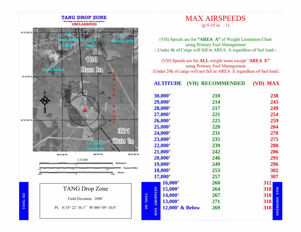
MAX AIRSPEEDS (p 5-15 in –1)
(VH) Speeds are for “AREA A” of Weight Limitation Chart
using Primary Fuel Management :::Under 4k of Cargo will fall in AREA A regardless of fuel load:::
(VD) Speeds are for ALL weight areas except “AREA E”
using Primary Fuel Management ::Under 24k of cargo will not fall in AREA E regardless of fuel load:: ALTITUDE (VH) RECOMMENDED (VD) MAX 30,000’ 210 238 29,000’ 214 243 28,000’ 217 249 27,000’ 221 254 26,000’ 225 259 25,000’ 228 264 24,000’ 231 270 23,000’ 235 275 22,000’ 239 280 21,000’ 242 286 20,000’ 246 291 19,000’ 249 296 18,000’ 253 302 17,000’ 257 307
16,000’ 260 312 15,000’ 264 318 14,000’ 267 318 13,000’ 271 318 12,000’ & Below 269 318
TA
NG
DZ
TA
NG
DZ
TANG Drop Zone
Field Elevation: 1090’
PI: N 35° 22’ 36.1” W 086° 09’ 10.0”
MA
X A
IRSPE
ED
S MA
X A
IRSP
EE
DS
To Space Institute
To Tullahoma
To Arnold AFB To 1750’
Tower
To Tims Ford
Lake
S A L V O
E A S T
1:25,000
86°9’30”W 86°9’0”W 86°8’30”W
35°23’0”N
35°22’30”N
35°23’30”N
Meters
Kilometers
Nautical Miles

mini 1801 E3Fiend
PRIORITY
<≡FF → ADDRESSEE(S)
<≡ FILING TIME ORIGINATOR SPECIFIC IDENTIFICATION OF ADDRESSEE(S) AND/OR ORIGINATOR 3. MESSAGE TYPE 7. AIRCRAFT IDENTIFICATION 8. FLIGHT RULES TYPE OF FLIGHT
<≡(FPL ⎯ M U S I C 8 7 ⎯ I M <≡9. NUMBER TYPE OF AIRCRAFT WAKE TURBULENCE CAT. 10. EQUIPMENT
⎯ C 1 3 0 / M ⎯ SHIRT DUK/C <≡ 13. DEPARTURE AERODROME TIME (Surveillance Equip: Mode S w/ Aircraft ID & Press Alt use: “/S”)
K B N A 0 4 2 015. CRUISING SPEED LEVEL ROUTE
⎯ N 0 3 0 0 F 1 3 0 → DCT MEM V123 LIT (note: use “DCT” to denote direct) (If Latitude and Longitude is required use format: 55N020W) <≡ 16. DESTINATION AERODROME
TOTAL EET HR/MIN
ALTN AERODROME 2ND ALTN AERODROME
⎯ K L I T 0 1 1 5 → T I S T → K E Y W <≡18. OTHER INFORMATION ⎯ EET/ MMFR 0051 KZMA 0252 (FIR Boundary Estimated Elapsed Times) REG/ 91187 (Aircraft Registration if Different From Item 7) OPR/ DOD (Name of Operator) NAV/ NON-FM IMMUNE VOR/ILS (If Non-Fm Immune, Item 10: ZHLOVDIRTFUK/C) RMK/ MDCN MM USA01 (Start w/ MDCN followed by: First 2 letters of FIR + DIP Number (Don’t Use ;:-/ in #)) RMK/ TIST PPR 1234 Requesting Fuel/RON RMK/ RCH designates Reach call sign (as per 6.13.2.2 p.74 11-2C-130 Vol 3)
NOT FOR TRANSMISSION 19. SUPPLEMENTARY INFORMATION
ENDURANCE PERSONS ON BOARD EMERGENCY AND SURVIVAL EQUIPMENT — FUEL / 8+00 → POB / 7 → RDO / 121.5 → 243 → 500 → 8364 <≡
TYPE OF EQUIPMENT LIFE JACKETS RADIO FREQUENCY
POLAR → DESERT → MARITIME → JUNGLE → GLOBAL → JACKETS → LIGHT → FLUORESCENT → 282.8 <≡ DINGHIES COLOR NUMBER TOTAL CAPACITY OTHER EQUIPMENT
DINGHIES → COVER CERISE 4/80 → RMK / SMOKE, MIRROR, FLARES, ELT ) <≡ REMARKS WX Briefed by _____ @ _____ (Initials @ Location)
AIRCRAFT SERIAL NUMBERS AND TYPE OF AIRCRAFT IN FLIGHT
CREW LIST ATTACHED LOCATED AT: KBNA AIR GUARD OPS 91187PASSENGER MANIFEST
ATTACHED LOCATED AT: KBNA AIR GUARD OPS C-130 NAME OF PILOT IN COMMAND SIGNATURE OF APPROVING AUTHORITY AIRCRAFT HOME STATION OR ORGANIZATION MAJ. MEHOGOFF KBNA
DD Form 1801, MAY 87 (COMPUTER GENERATED) DOD INTERNATIONAL FLIGHT PLAN
▐▐▐▐EFFECTIVE 15 APR 04▐▐▐▐ NASHVILLE INTL, TN (KBNA)
Rwy 20L, 20C, 20R, 1500-3* Rwy 31, 1500-3**
* Or Standard with minimum climb of 240/NM to 2600.
**Or Standard with minimum climb of 230/NM to 2600. Use TITAN DEPARTURE. TAKE-OFF OBSTACLES Rwy 31: Tower, 1472’ from DER, 916’ left of centerline, 143’ AGL/646’ MSL.
CHATTANOOGA, TN LOVELL FIELD (KCHA)
..Rwy 15, 300-1*
..Rwy 33, 500-1 * Or standard with minimum climb of
230/NM to 1700. Rwys 2, 15, 20, climb rwy hdg to 1700 before turning. Rwy 33, climb right turn to 2300 on hdg 020° before proceeding on course.
CAMBELL, AAF (KHOP) FORT CAMBELL, KY None.
HUNTSVILLE INTL-CARL T. JONES FLD (KHSV), AL
Rwys 36L and 36R climb rwy heading to 800 before turning
LEXINGTON, KY BLUE GRASS (KLEX) Rwy 4 and 8, climb rwy hdg to 1400 before turning.
KNOXVILLE, TN McGHEE TYSON (KTYS)
Comply with SID or RADAR vectors, or; climb rwy heading to 4000 before turning on curse
JACKSON, TN JACKSON / McKELLAR-SIPES REGIONAL (MKL) None.
IFR 3 ENGINE CLIMB
TR
OU
BL
E T
’s
1801 FLIG
HT
PLA
N 18
01 F
LIG
HT
PL
AN
TLocal Trouble ’s
Meets or exceeds highest of 200 Ft/NM or published departure climb gradient on 3 Eng.
YES
NO
3-engiene climb remains above Obstacle Intrusion Space -48’/NM
Compute 4-engine climb gradient
YES
DEPART
NO
YES
CAN’T
Meets or exceeds highest of 200 Ft/NM or published departure climb
di
At discretion of AC, all of the following apply (Guard requires home unit OG/CC Approval before exercising this option): ▪ Mission requirements dictate ▪ Day VFR on entire departure and planned emergency return route ▪ 4 engine climb meets highest of required climb gradient or 200 Ft/NM. ▪ AC determined through a review of charts that 3 eng Departure and Emer. Return will allow for obstacle avoidance.▪ Emer. return route is briefed to crew.
Reduce GW/FUEL, delay for WX, or Coord.
Alt DP w/ATC (Radar Vector must meet trouble T. 11-217 9.24)
XX
TR
OU
BL
E T
’s
VFR Depart (VFR Flt. Plan) ▪ 4 engine ensures obstacle clearance along Departure Route. Use 4eng Flt Path Chart -1-1 p3-88 ▪ 3 engine obstacle clearance on the planned departure & emer return. (minimum 300’/min & 152/nm)

FLT PLANNING WX REQRMTS
YES
NO
YES NO NO YES NO YES
YES
NO NO YES NO NO YES NO YES
WE
AT
HE
R W
EA
TH
ER
E
ME
R E
QU
IPME
NT
EM
ER
EQ
UIP
ME
NT
Departure Aircraft Is ceiling or visibility below
landing minimums for an available approach at
departure airport? (200-½min)
ISLAND OR REMOTE FORECAST WEATHER
(no alt w/in 2 hours) ▪Winds within limits corrected for RCR. If precision approach is available, ceiling and visibility may temporarily or intermittently drop below non-precision minimums (excluding ASR) but not below precision minimums. ▪If non-precision approach is available (except ASR) prevailing ceiling & visibility must be > published mins.
11 2C 130V3 81 6 20 3
IS DESTINATION AN ISLAND OR REMOTE?
File IFR to a point enroute where VMC conditions exist, or to a published approach, descend to VMC then VFR
to destination. REMINDERS: Check NOTAMS & TCN for changes.
C-130 X-wind limits: (p.9-8 in 1-1)
Dry: 35kts above 100lbsWet: 21kts above 100lbsAslts: 18kts@90˚ 28@30˚
DOES DEST REQUIRE AN ALTERNATE?
Alternate required if the worst WX (ETA + 1 hr)
is forecast to be less than:
Ceiling: 3000 ft
Visibility: 3 miles or 2 miles above lowest approach minimums whichever is higher.
Note: Tempo for thunder storms and/or rain showers is OK.
ALTERNATE REQUIRED: Worst forecast wx ETA + 1 hr must be: at least 1000ft or 500ft above
lowest approach minimums.- AND -
Visibility of 2 mi or 1 mi above lowest approach
minimums.
NO ALTERNATE REQUIRED
EXCEPTION: IS FLIGHT INTRA-THEATER AND LESS THAN THREE HOURS?
DESTINATION APPROACHES
▪Precision approaches may use vis only if fuel permits.
½ SM minimum. ▪All other approaches require
both ceiling and visibility.
11-2C-130V3 p98 6.42.1
Departure Alternate Required
Weather Mins for Takeoff: ▪ RVR > 1600 ▪ 1/2 mile if no RVR
This can be reduced to: ▪ RVR > 1000
If operational mission, runway has dual RVR
readouts & centerline lighting is operational.
WX at departure alternates:Within 30 mins flying time:
Wx must be > approach mins(in no case < 200-1/2(RVR 24)) for one hour after takeoff.
Within 2 hrs flying time:
Wx must be > 500-1 above approach mins but not <600-2 for a precision or <800-2 for a
non-precision approach (ETA + 1 hour)
Must be able to maintain MEA to alternate if an engine fails.
Is a published approachavailable?
DOES DESTINATION REQUIRE TWO ALTERNATES?
Is forecast weather (prevailing or intermittent) below visibility approach
minimums? - or -
Does wind exceed limits corrected for RCR?
DEPARTURE ALTERNATE NOT
REQUIRED
Weather Required For Takeoff: 1/2mile or >1600 RVR or >1000 w/ dual RVR Destination: 3000’ & 3 (or 2 above approach mins) Alternate: 1000’ & 2 (or 500’ & 1 above mins) If Approach Lighting Inop: add 1/2mile 2C-130V3 6.42.1.2 If < Full Flight Instrumentation: add 300 and 3/4miles 6.42.1.3
OCONUS flights requires an Alternate. IS DESTINATION OUTSIDE CONUS?
Is radar required? GPS only NAVAID? No WX Reporting?
NAVAID Unmonitored?
Must have enough O2 to continue mission from ETP (Equal Time Point). 5 liters min. POKs are required for PAX when ALT. exceeds FL250. EPOS are required regardless of ALT. You can’t mix POKs & EPOS. Crewmembers who do not have access to O2 will have either a POK or EEBD within arms reach 10,000’. On over water flights the max # of PAX is 80 due to Rafts. LPUs are required when outside gliding distance of land. You must wear LPUs ↓ 2000’ except takeoffs, landings, & approaches. LMs must wear a restraining harness or chute when doors are open. Harness only when 800’ agl

COCKPIT INSTRUMENT CHECK (AT BNA) 1. GENERAL a. Check alignment of attitude indicator
b. All steering bars/flags out of view c. Altimeter setting set - ± 70 field elevation
2. FLIGHT SELECTOR PANEL - HDG a. Set heading bug to airplane heading, steering bar should center. b. Rotate bug left/right, check proper steering bar deflection. 3. MODE SEL switch - TAC (Tune/Ident) BNA TACAN Channel 88X: − • • •, • −, − • Allow 90 sec for warm up a. MANUAL CHECK (1) FLT DIR switch - NORMAL (2) Ensure bearing pointer (BP) points to station. Check other TAC to be within ± 4° (3) Center CDI. Rotate course knob, check for proper displacement (Use 5° left/right
as a guide) (4) Check TO-FROM indicator changes at ~90° position. (5) Confirm Bearing/distance indications at TACAN checkpoint prior to flight. BP/CDI ±
4°, DME within ½mile or 3%. whichever greater (3% only applies when > 16nm DME)
b. SELF TEST (1) Set in 180° course and press TEST button (2) 7 sec: DME & NAV warning flags in view, BP=270° (3) 15 sec: Warning flags out of view, BP=180° (±3°), CDI ±½ dot, “TO” indicated,
DME 000 (±½ mile) 6. MODE SEL switch - VOR/ILS (Tune/Ident) BNA VOR Channel 114.1: − • • •, • −, − • a. Set 315 course and check for proper VOR identification b. Initiate TEST cycle (TUNE 5-5, VOR 1-1, Test “ON”) c. HSI BP indicates 315° ±3°, CDI centers, TO-FROM indicator displays “TO” d. Applicable bearing pointers indicates 315° ±3° e. All three marker beacon lights on pilot instrument panel illuminate steady (#1 VOR only) f. Press SCNS TEST button “OFF” 7. TUNE ADF Opery NDB Channel 344: • • • −, • •
a. Mode switch to “ADF”. b. Take Command switch to “Take Command”. c. Frequency Control switch to “MAN” and tune and identify the desired frequency. d. Test/Tone switch to “Test” and hold. e. ADF pointer advances 90° from original position. f. Release Test/Tone switch. g. ADF pointer returns to original position.
8. RADAR ALTIMITER a. Set altitude reference to 400΄ b. Press & release the SET control knob.
(1) Height Indicator Test Display (a) Alt pointer positioned at 500΄ (b) Digital display shows 88888 (c) R/T light illuminated (2) Receiver-Transmitter Test Display (a) Alt pointer positioned at 300΄ (b) Digital display 300΄ (±10΄) (c) R/T light off (d) LO light illuminated (e) System returns to normal ops after ~3 sec.Digital display shows 0΄ (±2΄)
DEPARTURE BRIEFING 1. TOLD Airspeeds Runway required for Takeoff vs Runway Available
Vref < Vto -- acceleration check time 50 % flap ground roll (E) 2. EMERGENCY PROCEDURES Prior to refusal speed -- “reject prop/eng/sys/load (brief description)” - Prop - (2 of top 3, prop low oil light, directional control) Flight idle / ESP / reverse symetricals - anything else (no rush) Gnd idle / reverse all 4 (if necessary) / wait ‘til safe taxi speed After refusal speed - Treat as an airborne emergency //// option if on long runway - Advisory call Prop / engine failure -- Gear , FX, Flaps Obstacles : gear w/i 3 // fx w/i 6 // 3 eng climb speed to MSA (N) keep us clear of obstacles No obstacles : try for 150 KTAS -- Vmca2 (E) - clear to go MECH Engine fire / overheat -- keep it running Anything else we’ll handle after clear from ground Fuel dumping / bleeds (> 120k 2 eng min performance) (E) Recovery base ? (wx bad -- IAP) Copilot & Flight Engineer coordinate Emergency Actions. 3. SIGNALS FOR GEAR AND FLAP RETRACTION 4. DEPARTURE SID / RV / Clearance ALT / HDG Nav Aids SCNS - overview of plan Radar Alt - (400’ or HAT) Hazardous terrain / obstacles (N) Radar Monitoring for WX (N)
ITO-select heading, pitch sync, rotate speed – MCS or 5 kts prior, pitch 7°, two positive rates – gear, climb > 300 fpm, flaps +20,
5. SKE / FORMATION PROCEDURES SKE - (CP) Abort Calls - (CP - ATC / N - interplane)
6. SCNS PROCEDURES Fly in SCNS // Radial/ DME
7. Defensive/ECM Systems
8. Notes/Unit/MAJCOM Items
BR
IEFIN
G: D
epartureBR
IEFI
NG
: D
epar
ture
ATIS: DEP 135.675 ARR 135.1
CLNC DEL: 126.05 GND CON: 121.9 TWR: 118.6
INSTR
UM
ENT C
HEC
K
INST
RU
MEN
T C
HEC
K

ARRIVAL BRIEFING VFR CHART 1. WEATHER -- ATIS // METRO // FSS 2. APPROACH TO BE USED Flap setting // type landing // speeds//runway available vs. desired ldg dis. Navaids // Obstacles // ESA//MSA? Course Descent rate Precision : drift / gnd speed (N) Non-precision : 1500 fpm (CP) backup // Drift (N)
Altitudes -- FAF / HAT/MDA/DH/Radar Altimeter? Timing -- calculate and backup “hack” (N)
Touchdown point and Landing Distance (E) - “speed good” // “props good”
3. BACKUP APPROACH Vis // Loc // anything close // missed approach 4. MISSED APPROACH Initial hdg / alt // (N) read the rest (E) - call 7,8,9 or 15,16,17
FUEL PLANNING (Explanation of Fuel Items on AF Form 4116, C-130 Flight Plan and Record)
En Route Fuel for flight time from departure overhead destination or initial penetration fix at cruise altitude (including time for planned orbit, escort, search, recovery, appropriate climb, weather recon, etc. when applicable).
En Route Reserve
10% of flight time over a Category I remote/segment, not to exceed 0+45 minutes. For orbit/search missions, 10% of flight time for that portion with inadequate NAVAIDS from the orbit/search point to destination. Compute at Terminal Fuel Flow (TTF is the fuel flow rate expected during the last hour at cruise altitude 11-2C-130V3 p.428).
Alternate and Missed
Approach
Alternate: Fuel for flight time from overhead destination or initial penetration fix to alternate, or most distant alternate when two are required. Compute at terminal fuel flow. Add 10% reserve when time to an alternate exceeds 1+30. Required whenever an alternate must be filed. Missed Approach: 2200 lbs. Required if destination is below ceiling minimums but above visibility minimums for planned destination approach.
Holding Entry required. Minimum 2000 lbs. If flight time over a Category II route is greater than 3+20, when an alternate is located in Alaska, is not available or located at latitudes greater than 59o N/S, use 3500 lbs. These holding fuel calculations meet or exceed the fuel requirements of AFI 11-202V3 2.2.3. Fuel Reserve.
Approach/ Landing
Approach: 1,000 lbs. (2,000 lbs for high altitude approach). Entry always required. Minimum Landing Fuel: 4,000 lbs. Entry always required.
Pressurization Loss
Additional fuel for pressure loss at ETP (Equal Time Point) - used when pressurized, carrying passengers, and aircraft oxygen is not available to the passengers. Compute at 1000 lbs/hr for time from ETP to FSAF (First Suitable Airfield) or LSAF (Last Suitable Airfield) or “T” time . If computed fuel reserve for pressurization loss is less than total of items 2, 4, 5, and 12, no additional entry required in item 7. If computed fuel exceeds the total of items 2, 4, 5, and 12, add the difrence in item 7.
Stored Fuel Ramp fuel for succeeding legs without refueling.
Off-Course Maneuvers
Fuel for anticipated off-course maneuvering for terrain clearance, thunderstorm avoidance, ATC requirements. Compute at 100 lbs/min for departure, 50 lbs/min for en route
Icing 500 lbs for each hour of anticipated icing.
Known Holding Delays
Fuel for anticipated/planned excess holding time. Compute at terminal fuel flow.
Taxi and Takeoff
Normally 1300 lbs. For known taxi delays or additional engine-running ground time in excess of 20 minutes, add 50 lbs/min.
Unidentified Extra
Difference between ramp and actual ramp fuel. Should not exceed 2200 lbs (for fuel conservation purpose).
Minimum Diversion
Total of ALTERNATE AND MISSED APPROACH, HOLDING, and APPROACH/LANDING. Will never be less than 7000 lbs.
Min Fuel Declare when aircraft will land at the intended destination with less than the required fuel reserve.
Balance: Outboards 500-1,000lbs > inboards; 1,000lbs between symmetricals; 1,500 between wings. Assault Fuels: <6,200 in outboards, 0 in externals, <23,500 total in mains, 130,000lbs max gross weight Primary Fuel Management: Main tanks are full and in balance (see above) and the external and / or auxiliary
tanks contain usable fuel. Main tanks are considered full with > 7,500 lbs in the outboards; > 6,900 lbs in the inboards. This is our chief means of fuel management. Secondary Fuel Management: Any fuel management that fails to meet Primary fuel management. 118AW will not normally operate in Secondary Fuel Management.
Usable Fuel in Level Flight (foam in tanks)
TANK U.S. GALLONS JP-8, POUNDS Outboards 1222 8310 Inboards 1126 7657
Auxiliaries 855 5814 Externals 1309 8901 TOTALS 9024 61,364
FUE
L FU
EL
B
RIE
F: Arrival B
RIE
F: A
rriv
al
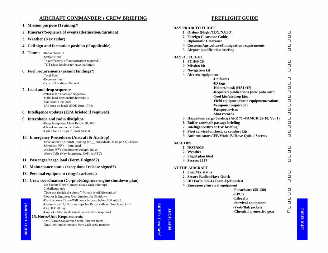
AIRCRAFT COMMANDER's CREW BRIEFING
1. Mission purpose (Training?)
2. Itinerary/Sequence of events (destination/duration)
3. Weather (Nav radar)
4. Call sign and formation position (if applicable)
5. Times: -Radio check-in -Stations time -Takeoff (early off authorization required?) -TOT (does loadmaster have the times)
6. Fuel requirements (assault landings?) -Total Fuel -Recovery Fuel -Type of Landings Planned
7. Load and drop sequence -What is the Load and Sequence -Is the load Jettisonable/hazardous -Nav Marks the loads -JAI done on load? (DOD form 1748)
8. Intelligence updates (EPA briefed if required)
9. Interphone and radio discipline -Keep Interphone Clear Below 10,000ft -Clear/Concise on the Radio -Listen for Callsign if Pilots Miss it
10. Emergency Procedures (Aircraft & Airdrop) -Evacuation of Aircraft (looking for __ individuals, load get O2/Chocks -Simulated EP’s--”simulated” -Airdrop EP’s (loadmaster/cockpit duties) -Abort Calls (Nav-Interplane, CoPilot-ATC)
11. Passenger/cargo load (Form F signed?)
12. Maintenance status (exceptional release signed?)
13. Personal equipment (rings/scarfs/etc.)
14. Crew coordination (Co-pilot/Engineer engine shutdown plan) -No Secrets/Crew Concept (Back each other up) -2 challenge rule -Time-out (inside the aircraft)/Knock-it-off (formation) -Copilot & Engineer Coordination for Shutdown -Preslowdown Times/Will doors be open below 800 AGL? -Engineer call 7,8,9 on run-ups/No Reject calls on Touch and Go’s -Eng; IFF all day -Copilot – Stop mode (most conservative response) 15. Notes/Unit Requirements
-AMC/Group/Squadron Special Interest Items -Questions and comments from each crew member
PREFLIGHT GUIDE
DAY PRIOR TO FLIGHT 1. Orders (Flight/TDY/NATO) 2. Foreign Clearance Guide 3. Diplomatic Clearance 4. Customs/Agriculture/Immigration requirements 5. Airport qualification briefing
DAY OF FLIGHT 1. FCIF/FCB 2. Mission kit 3. Navigation kit 4. Aircrew equipment: -Uniforms -ID tags -Helmet/mask (HALO?) -Required publications (new pubs out?) -Tool kits/airdrop kits -Field equipment/artic equipment/rations -Weapons (required?) -Passports/visas -Shot records 5. Hazardous cargo briefing (AFR 71-4/AMCR 55-18, Vol 1) 6. Buffer zone/safe passage briefing 7. Intelligence/threat/EW briefing 8. Fleet service/lunches/pax comfort kits 9. Authenticators/IFF/Mode IV/Have Quick/ Secrets
BASE OPS 1. NOTAMS 2. Weather 3. Flight plan filed 4. Secrets ????
AT THE AIRCRAFT 1. Fuel/MX status 2. Secure Radios/Have Quick 3. DD Form 365-4 (Form-F)/Manifest 4. Emergency/survival equipment: -Parachutes (55-130) -LPU's -Liferafts -Survival equipment -Vests/flak jackets
-Chemical protective gear
BR
IEF: C
rew B
rief BR
IEF:
Cre
w B
rief
PR
EFL
IGH
T PR
EFL
IGH
T

Airdrop Equipment Info Drop Airspeeds: For combo, use the higher airspeed AFI 11-231 p125
Personnel SL 130 CDS/CRS 130/140* PJs 125 Door Bundle 130 Personnel HALO/HAHO 110min-150max 130 CRRC/RAMZ/HVCDS 130/140*
Heavy Equipment 140 Recovery Kit 130
*Used when GW > 120k Must be operational: Personnel Airdrop Air Deflector& Paratroop Doors (if using paratroop doors) Anchor cables Anchor cable supports Static line retrievers Jump platforms Jump lights Seats (64) Towed Paratroop Retrieval System Container Delivery System (CDS) Static line retriever CDS switch Arming jump lights Ramp & door w/ADS arms Main DC power through TD relay for ADS Operational Aux pump & system Dual rails Chain gate Buffer stop assembly Centerline vertical restraint (CVR) Heavy Equipment Dual rails and locks Extraction parachute ejector (bomb rack) Ramp & door w/ADS arms Operational ADS panel Operational Aux pump & system Jump lights Wind Limits for Personnel: If surface winds unknown, inform JM if alt winds >30kts SL land 13 PJs SL water 22 SL water 17 PJs HGRP water 25 MFF land 18 PJs trees 17 MFF water 20 Non-AF SL User
Wind Limits for Equipment AF Equipment 17 HVCDS NoneCDS G-12 13 SATB 25 CDS G-13/14 20 Non-AF equipment User
Engine Out Information
Engine Shutdown Procedures Squak / Systems / Si multaneous Radios -set TA only on transponder -state fuel in WT (for fire crew) and Time (SAR) Trim- Rudder Neutral on Final (FE backup) Airspeeds- Vmca, Obst clnc, 3 Eng climb Reversing Symmetricals (FE backup) -Pull towards the goods -Put dead engine upwind GO Around Procedures- Inform Crew -Max Power/5° Bank & Rudder -50% Flaps/Gear Up/2 Eng Vmca -Flaps Up/3 Eng Climb
Decent and/or Before Landing
The Patterns 3/4 ENGINES Downwind 150/170 Base 150 or Approach Speed (140 VFR) Final Approach Speed 2 ENGINES Downwind 160 (w/ gear) Base 160 or Approach Speed Dogleg 150 or Approach Speed Final 150 or Approach Speed Short Final Flaps when landing assured WINDS Dead Engine away from the wind for easier approach Dead Engine into wind for easier landing / rollout
2 Engine Out Information Configuration: #1 & #2 Out: Flaps up, Gear down Circuit Breaker: Wing Flap Control CB, Flap Lever 50% Hydraulics (#1 & #2 Out only): Cover NW Steering, Emerg Brakes Electrics: Reduce/Monitor Load on Generators Weight: Dump Fuel / Salvo Load < 120k Bleeds Closed Airspeeds: Review Pattern and Approach Speeds Ground Idle: Inboard First Pumps / Brakes A
IRD
RO
P L
IMIT
S AIR
DR
OP L
IMIT
S
EN
GIN
E O
UT
EN
GIN
E O
UT

Combat Offload Guide PREPARATION: In a hostile environment, the crew briefing may be performed before the combat entry point. (The main purpose is minimal time on the ground) LOADMASTER: »Get a communication check of PA system »Let LM know when cleared to open ramp/door »Taxi route will not cross a runway »Pressurization off »Tell Pilot when preparation checks are complete. ENGINEER: »Runs the Annex A checklist »Have new TOLD completed COPILOT: »Clear right side NAVIGATOR: »Turn PA on and speaker selector switch to all usually positioned at bottom of flightdeck »Safety observer: clearing aft PILOT: »Can I do it? (ATO/SPINS) exception on 2.18.1.1 »Where will I do it? min of 500’/1000’ desired »Which method? (A or B) »A for single, multiple, ramp or married pallets; airdrop platforms; and CDS »B for all else (remember 55 gal drums required) »Consider ACMs (crew chief) as lookout for left side »Select INT/PA on pilot side for PA check (must check with INT not HOT MIKE) »Brief execution duties EXECUTION: LOADMASTER: »Notify P when clear to taxi »Let P know of any malfunction »Tell P when load is clear ENGINEER: »Runs the checklist »Back P up on torques »Monitor engine performance COPILOT: »Clear right side »Back up P on power/brakes NAVIGATOR: »PA on »Notify P when in position (bottom of flight deck) PILOT: »Coordinate with crew of intentions for malfunctions/ran out of space »select INT/PA on pilot side »Tech: P on INT and CP with ATC; both on HOT MIC »Notify LM when parking brake set »Set 5,000# torque (conditions permitting) »Release brakes and listen for LOAD CLEAR »Apply brakes (reverse if space is limited) »PA switch to interphone »Wait for offload checks complete call »Resume mission
LIMITS: »No explosives without MAJCOM/DO approval »500’ min 1000’ desired »If fragile you may lower ramp to 18” »Single airdropped rigged platforms (< 24’) ok if < 12,000lbs »Double or triple pallets ok if < 12,000lbs and height is good »if > 12,000lbs the front of the aircraft will require ballast (note: a 17,000lbs will require 5,000lbs ballast. 17-12=5) »CDS if >12,000lbs & CVR then do 1 side at a time, 1f >12,000lbs & no CVR do <4 bundles at a time.
Engine Out Information Cont.
ENGINE SHUTDOWN CONDITIONS Turbine Overheat Throttle Control Cable Failure TIT (uncontrollable rise) Oil Pressure (uncontrollable drop) Oil Temperature (uncontrollable rise) Power (uncontrollable) Prop Malfunctions (some) Nacelle Overheat Engine Fire Visible Fluid Leak Unusual Vibrations/Roughness Start Valve Open (light illuminated) Hydraulic pressure >3900 (cruise engine shutdown)
ENGINE FIRE HANDLE Engine Fuel Control Shutoff Valve Closed Engine Oil Shutoff Valve Closed Firewall Fuel Shutoff Valve Closed Firewall Hydraulic Shutoff Valves Closed Engine Bleed Air Shut Off Engine Starting Control Circuits Deenergized Prop Feathered Fire Extinguishers Positioned Agent Discharge Switch Armed
APU/GTC FIRE HANDLE Fuel Shutoff Valve Closed Oil Shutoff Valve Closed (GTC) Bleed Air Valve Closed Fire Extinguishers Positioned Agent Discharge Switch Armed Door Closed (APU)/Disarmed (GTC)
BR
IEF: Com
bat OffLoadB
RIE
F: C
omba
t Off
Load
E
NG
INE
OU
T E
NG
INE
OU
T

REVERSE TAXI 1. RESTRICTIONS a. 25 feet from all Obstacles b. Cargo secured and Passengers seated c. Ramp 12 inches above horizontal d. Clear area in front of aircraft 2. PREPARATION/BRIEFING a. Complete After Landing Checklist or Before Taxi Checklist (as appropriate) b. Brief Crewmembers/Loadmaster on Reverse Taxi - “Clear all obstacles for 25 feet/reverse taxi path” - “Turn towards number 1 or 4 engine” - “Use more turn and less turn terminology” - “Countdown to stop 5,4,3,2,1” - “Talk continuously, if stop talking, stop backing”
- “For Emergency Stop use STOP, STOP, STOP” - Try to put aircraft on taxi line if able
- If night, ensure proper illumination 3. EXECUTION
a. Brief crew on direction of turn out b. Ensure all four engines are on-speed c. Confirm all engine oil temperatures 60-85 degrees d. Release brakes and announce “off brakes” (do not let the aircraft roll
forward) e. Pilot and Co-Pilot feet on floor f. Do not use brakes g. LM keep talking, if stop talking, stop backing h. Put all throttles in reverse symmetrically i. Taxi no faster than a brisk walk j. Slow aircraft with forward thrust k. Taxi 5 feet forward to align gear prior to stopping l. Questions
NOTE: 1. If any engine oil temperature exceeds 100 degrees, abort the
reverse taxi by taxiing forward to center the nosewheel and then stop to cool the engines. 2. Although the LM is primary for directing reverse taxi, anyone can call to stop the aircraft for safety, including the marshaller.
Quick-Don Preflight (ref -1 p 1-223)
Static pressure: 270-455 psi, Continuous breathing: 270-340 psi
1. Supply Lever – OFF
2. Diluter Lever – 100%
3. Attempt to Breath (If you can you have a faulty regulator)
4. Supply Lever – ON
5. Emergency Toggle Lever – EMERGENCY
6. Don the goggles and adjust for proper fit. Ensure the eyewash pin is
IN
7. 3 Breathing Cycles – White in, Black out
8. Hold breath and open the eyewash purge valve. The blinker should go
from black to white indicating the ports to the goggles are clear
9. Emergency Toggle Lever – NORMAL
10. 3 Breathing Cycles – White in, Black out
11. Eyewash Pin – OUT for flight
12. Leave in NORMAL, 100%, ON, Oxygen Hose – Connected
Note: For stowage purposes after flight the eyewash pin should be pushed in.
OX
YG
EN
OX
YG
EN
B
RIE
F: Reverse T
axi BR
IEF:
Rev
erse
Tax
i
BR
IEF: E
RO
BR
IEF:
ER
O
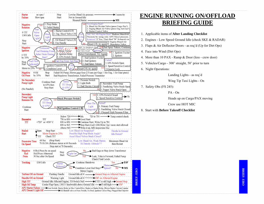
ENGINE RUNNING ON/OFFLOAD BRIEFING GUIDE
1. Applicable items of After Landing Checklist
2. Engines - Low Speed Ground Idle (check SKE & RADAR)
3. Flaps & Air Deflector Doors - as req’d (Up for Dirt Ops)
4. Face into Wind (Dirt Ops)
4. More than 10 PAX - Ramp & Door (less - crew door)
5. Vehicles/Cargo - 300’ straight, 50’ prior to turn
6. Night Operations:
Landing Lights - as req’d
Wing Tip Taxi Lights - On
7. Safety Obs (FS 245):
PA - On
Heads up on Cargo/PAX moving
Crew use HOT MIC
8. Start with Before Takeoff Checklist
BR
IEF: E
RO
BR
IEF:
ER
O
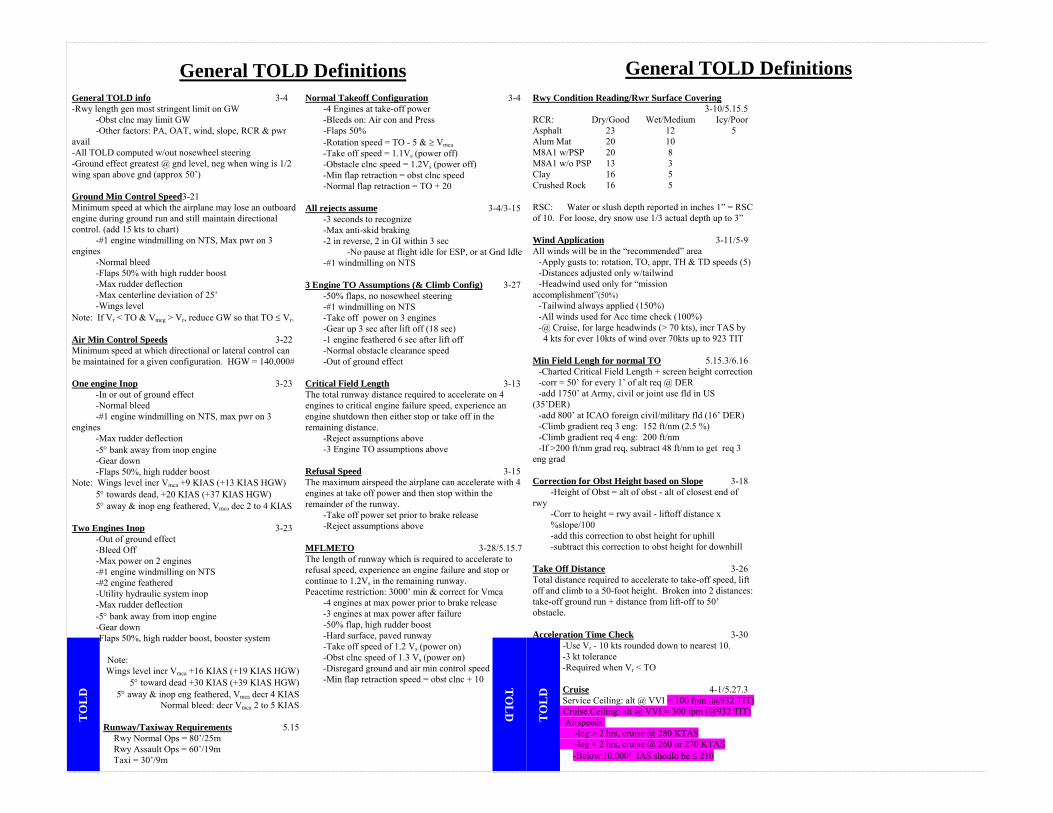
General TOLD info 3-4 -Rwy length gen most stringent limit on GW -Obst clnc may limit GW -Other factors: PA, OAT, wind, slope, RCR & pwr avail -All TOLD computed w/out nosewheel steering -Ground effect greatest @ gnd level, neg when wing is 1/2 wing span above gnd (approx 50’) Ground Min Control Speed3-21 Minimum speed at which the airplane may lose an outboard engine during ground run and still maintain directional control. (add 15 kts to chart) -#1 engine windmilling on NTS, Max pwr on 3 engines -Normal bleed -Flaps 50% with high rudder boost -Max rudder deflection -Max centerline deviation of 25’ -Wings level Note: If Vr < TO & Vmcg > Vr, reduce GW so that TO ≤ Vr. Air Min Control Speeds 3-22 Minimum speed at which directional or lateral control can be maintained for a given configuration. HGW = 140,000# One engine Inop 3-23 -In or out of ground effect -Normal bleed -#1 engine windmilling on NTS, max pwr on 3 engines -Max rudder deflection -5° bank away from inop engine -Gear down -Flaps 50%, high rudder boost Note: Wings level incr Vmca +9 KIAS (+13 KIAS HGW) 5° towards dead, +20 KIAS (+37 KIAS HGW) 5° away & inop eng feathered, Vmca dec 2 to 4 KIAS Two Engines Inop 3-23 -Out of ground effect -Bleed Off -Max power on 2 engines -#1 engine windmilling on NTS -#2 engine feathered -Utility hydraulic system inop -Max rudder deflection -5° bank away from inop engine -Gear down -Flaps 50%, high rudder boost, booster system Note:
Wings level incr Vmca +16 KIAS (+19 KIAS HGW) 5° toward dead +30 KIAS (+39 KIAS HGW)
5° away & inop eng feathered, Vmca decr 4 KIAS Normal bleed: decr Vmca 2 to 5 KIAS
Runway/Taxiway Requirements 5.15
Rwy Normal Ops = 80’/25m Rwy Assault Ops = 60’/19m Taxi = 30’/9m
Normal Takeoff Configuration 3-4 -4 Engines at take-off power -Bleeds on: Air con and Press -Flaps 50% -Rotation speed = TO - 5 & ≥ Vmca -Take off speed = 1.1Vs (power off) -Obstacle clnc speed = 1.2Vs (power off) -Min flap retraction = obst clnc speed -Normal flap retraction = TO + 20 All rejects assume 3-4/3-15 -3 seconds to recognize -Max anti-skid braking -2 in reverse, 2 in GI within 3 sec -No pause at flight idle for ESP, or at Gnd Idle -#1 windmilling on NTS 3 Engine TO Assumptions (& Climb Config) 3-27 -50% flaps, no nosewheel steering -#1 windmilling on NTS -Take off power on 3 engines -Gear up 3 sec after lift off (18 sec) -1 engine feathered 6 sec after lift off -Normal obstacle clearance speed -Out of ground effect Critical Field Length 3-13 The total runway distance required to accelerate on 4 engines to critical engine failure speed, experience an engine shutdown then either stop or take off in the remaining distance. -Reject assumptions above -3 Engine TO assumptions above Refusal Speed 3-15 The maximum airspeed the airplane can accelerate with 4 engines at take off power and then stop within the remainder of the runway. -Take off power set prior to brake release -Reject assumptions above MFLMETO 3-28/5.15.7 The length of runway which is required to accelerate to refusal speed, experience an engine failure and stop or continue to 1.2Vs in the remaining runway. Peacetime restriction: 3000’ min & correct for Vmca -4 engines at max power prior to brake release -3 engines at max power after failure -50% flap, high rudder boost -Hard surface, paved runway -Take off speed of 1.2 Vs (power on) -Obst clnc speed of 1.3 Vs (power on) -Disregard ground and air min control speed -Min flap retraction speed = obst clnc + 10
Rwy Condition Reading/Rwr Surface Covering 3-10/5.15.5 RCR: Dry/Good Wet/Medium Icy/Poor Asphalt 23 12 5 Alum Mat 20 10 M8A1 w/PSP 20 8 M8A1 w/o PSP 13 3 Clay 16 5 Crushed Rock 16 5 RSC: Water or slush depth reported in inches 1” = RSC of 10. For loose, dry snow use 1/3 actual depth up to 3” Wind Application 3-11/5-9 All winds will be in the “recommended” area -Apply gusts to: rotation, TO, appr, TH & TD speeds (5) -Distances adjusted only w/tailwind -Headwind used only for “mission accomplishment”(50%) -Tailwind always applied (150%) -All winds used for Acc time check (100%) -@ Cruise, for large headwinds (> 70 kts), incr TAS by 4 kts for ever 10kts of wind over 70kts up to 923 TIT Min Field Lengh for normal TO 5.15.3/6.16 -Charted Critical Field Length + screen height correction -corr = 50’ for every 1’ of alt req @ DER -add 1750’ at Army, civil or joint use fld in US (35’DER) -add 800’ at ICAO foreign civil/military fld (16’ DER) -Climb gradient req 3 eng: 152 ft/nm (2.5 %) -Climb gradient req 4 eng: 200 ft/nm -If >200 ft/nm grad req, subtract 48 ft/nm to get req 3 eng grad Correction for Obst Height based on Slope 3-18 -Height of Obst = alt of obst - alt of closest end of rwy
-Corr to height = rwy avail - liftoff distance x %slope/100
-add this correction to obst height for uphill -subtract this correction to obst height for downhill Take Off Distance 3-26 Total distance required to accelerate to take-off speed, lift off and climb to a 50-foot height. Broken into 2 distances: take-off ground run + distance from lift-off to 50’ obstacle. Acceleration Time Check 3-30 -Use Vr - 10 kts rounded down to nearest 10. -3 kt tolerance -Required when Vr < TO
Cruise 4-1/5.27.3 Service Ceiling: alt @ VVI = 100 fpm (@932 TIT)
Cruise Ceiling: alt @ VVI = 300 fpm (@932 TIT) Airspeeds: -leg > 2 hrs, cruise @ 280 KTAS -leg < 2 hrs, cruise @ 260 or 270 KTAS
-Below 10,000’ IAS should be ≤ 210
General TOLD Definitions
General TOLD Definitions T
OL
D
TO
LD
TO
LD
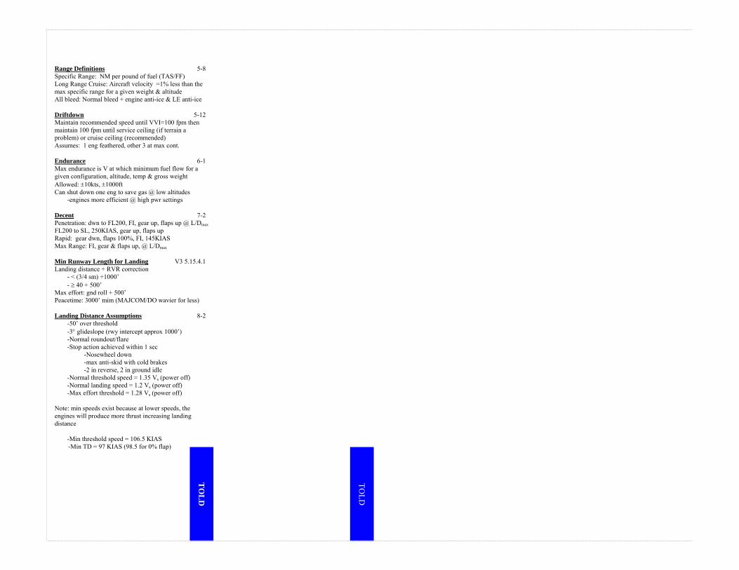
Range Definitions 5-8 Specific Range: NM per pound of fuel (TAS/FF) Long Range Cruise: Aircraft velocity =1% less than the max specific range for a given weight & altitude All bleed: Normal bleed + engine anti-ice & LE anti-ice Driftdown 5-12 Maintain recommended speed until VVI=100 fpm then maintain 100 fpm until service ceiling (if terrain a problem) or cruise ceiling (recommended) Assumes: 1 eng feathered, other 3 at max cont. Endurance 6-1 Max endurance is V at which minimum fuel flow for a given configuration, altitude, temp & gross weight Allowed: ±10kts, ±1000ft Can shut down one eng to save gas @ low altitudes -engines more efficient @ high pwr settings Decent 7-2 Penetration: dwn to FL200, FI, gear up, flaps up @ L/Dmax FL200 to SL, 250KIAS, gear up, flaps up Rapid: gear dwn, flaps 100%, FI, 145KIAS Max Range: FI, gear & flaps up, @ L/Dmax Min Runway Length for Landing V3 5.15.4.1 Landing distance + RVR correction - < (3/4 sm) +1000’ - ≥ 40 + 500’ Max effort: gnd roll + 500’ Peacetime: 3000’ mim (MAJCOM/DO wavier for less) Landing Distance Assumptions 8-2 -50’ over threshold -3° glideslope (rwy intercept approx 1000’) -Normal roundout/flare -Stop action achieved within 1 sec -Nosewheel down -max anti-skid with cold brakes -2 in reverse, 2 in ground idle -Normal threshold speed = 1.35 Vs (power off) -Normal landing speed = 1.2 Vs (power off) -Max effort threshold = 1.28 Vs (power off) Note: min speeds exist because at lower speeds, the engines will produce more thrust increasing landing distance -Min threshold speed = 106.5 KIAS
-Min TD = 97 KIAS (98.5 for 0% flap)
TO
LD
TOLD
DR
OP
EM
ER
GE
NC
IES
TIM
ING
& T
echn
ique
s
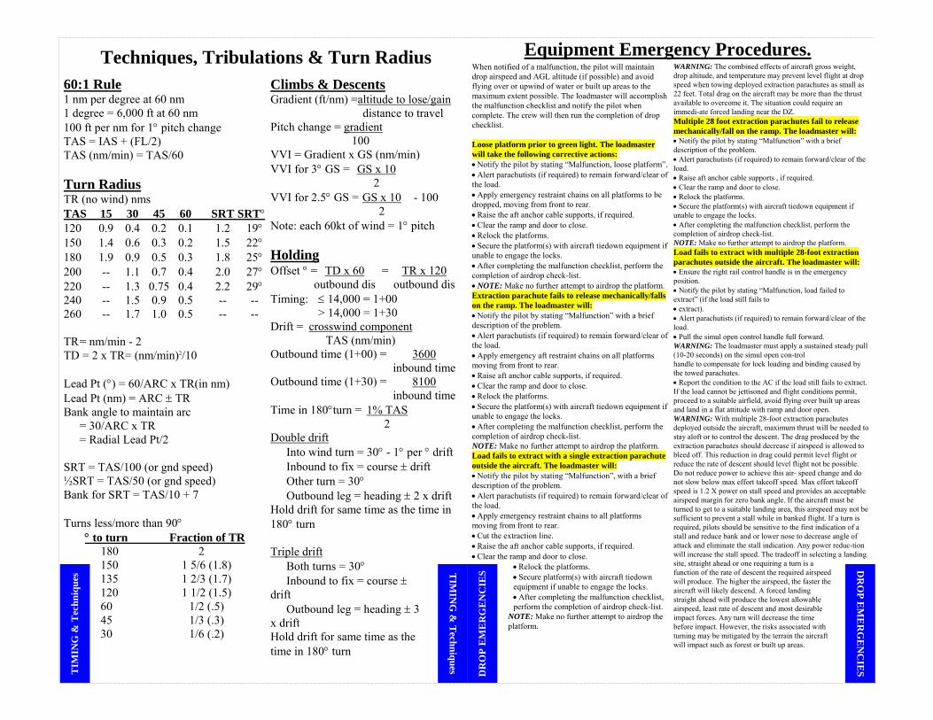
60:1 Rule 1 nm per degree at 60 nm 1 degree = 6,000 ft at 60 nm 100 ft per nm for 1° pitch change TAS = IAS + (FL/2) TAS (nm/min) = TAS/60 Turn Radius TR (no wind) nms TAS 15 30 45 60 SRT SRT° 120 0.9 0.4 0.2 0.1 1.2 19° 150 1.4 0.6 0.3 0.2 1.5 22° 180 1.9 0.9 0.5 0.3 1.8 25° 200 -- 1.1 0.7 0.4 2.0 27° 220 -- 1.3 0.75 0.4 2.2 29° 240 -- 1.5 0.9 0.5 -- -- 260 -- 1.7 1.0 0.5 -- -- TR = nm/min - 2 TD = 2 x TR= (nm/min)2/10 Lead Pt (°) = 60/ARC x TR(in nm) Lead Pt (nm) = ARC ± TR Bank angle to maintain arc = 30/ARC x TR = Radial Lead Pt/2 SRT = TAS/100 (or gnd speed) ½SRT = TAS/50 (or gnd speed) Bank for SRT = TAS/10 + 7 Turns less/more than 90°
° to turn Fraction of TR 180 2 150 1 5/6 (1.8) 135 1 2/3 (1.7) 120 1 1/2 (1.5) 60 1/2 (.5) 45 1/3 (.3) 30 1/6 (.2)
Climbs & Descents Gradient (ft/nm) =altitude to lose/gain distance to travel Pitch change = gradient 100 VVI = Gradient x GS (nm/min) VVI for 3° GS = GS x 10 2 VVI for 2.5° GS = GS x 10 - 100 2 Note: each 60kt of wind = 1° pitch Holding Offset ° = TD x 60 = TR x 120 outbound dis outbound dis Timing: ≤ 14,000 = 1+00 > 14,000 = 1+30 Drift = crosswind component TAS (nm/min) Outbound time (1+00) = 3600 inbound time Outbound time (1+30) = 8100 inbound time Time in 180°turn = 1% TAS 2 Double drift Into wind turn = 30° - 1° per ° drift Inbound to fix = course ± drift Other turn = 30° Outbound leg = heading ± 2 x drift Hold drift for same time as the time in 180° turn Triple drift Both turns = 30° Inbound to fix = course ± drift Outbound leg = heading ± 3 x drift Hold drift for same time as the time in 180° turn
When notified of a malfunction, the pilot will maintain drop airspeed and AGL altitude (if possible) and avoid flying over or upwind of water or built up areas to the maximum extent possible. The loadmaster will accomplish the malfunction checklist and notify the pilot when complete. The crew will then run the completion of drop checklist. Loose platform prior to green light. The loadmaster will take the following corrective actions: • Notify the pilot by stating “Malfunction, loose platform”. • Alert parachutists (if required) to remain forward/clear of the load. • Apply emergency restraint chains on all platforms to be dropped, moving from front to rear. • Raise the aft anchor cable supports, if required. • Clear the ramp and door to close. • Relock the platforms. • Secure the platform(s) with aircraft tiedown equipment if unable to engage the locks. • After completing the malfunction checklist, perform the completion of airdrop check-list. • NOTE: Make no further attempt to airdrop the platform. Extraction parachute fails to release mechanically/falls on the ramp. The loadmaster will: • Notify the pilot by stating “Malfunction” with a brief description of the problem. • Alert parachutists (if required) to remain forward/clear of the load. • Apply emergency aft restraint chains on all platforms moving from front to rear. • Raise aft anchor cable supports, if required. • Clear the ramp and door to close. • Relock the platforms. • Secure the platform(s) with aircraft tiedown equipment if unable to engage the locks. • After completing the malfunction checklist, perform the completion of airdrop check-list. NOTE: Make no further attempt to airdrop the platform. Load fails to extract with a single extraction parachute outside the aircraft. The loadmaster will: • Notify the pilot by stating “Malfunction”, with a brief description of the problem. • Alert parachutists (if required) to remain forward/clear of the load. • Apply emergency restraint chains to all platforms moving from front to rear. • Cut the extraction line. • Raise the aft anchor cable supports, if required. • Clear the ramp and door to close.
• Relock the platforms. • Secure platform(s) with aircraft tiedown equipment if unable to engage the locks. • After completing the malfunction checklist, perform the completion of airdrop check-list.
NOTE: Make no further attempt to airdrop the platform.
WARNING: The combined effects of aircraft gross weight, drop altitude, and temperature may prevent level flight at drop speed when towing deployed extraction parachutes as small as 22 feet. Total drag on the aircraft may be more than the thrust available to overcome it. The situation could require an immedi-ate forced landing near the DZ. Multiple 28 foot extraction parachutes fail to release mechanically/fall on the ramp. The loadmaster will: • Notify the pilot by stating “Malfunction” with a brief description of the problem. • Alert parachutists (if required) to remain forward/clear of the load. • Raise aft anchor cable supports , if required. • Clear the ramp and door to close. • Relock the platforms. • Secure the platform(s) with aircraft tiedown equipment if unable to engage the locks. • After completing the malfunction checklist, perform the completion of airdrop check-list. NOTE: Make no further attempt to airdrop the platform. Load fails to extract with multiple 28-foot extraction parachutes outside the aircraft. The loadmaster will: • Ensure the right rail control handle is in the emergency position. • Notify the pilot by stating “Malfunction, load failed to extract” (if the load still fails to • extract). • Alert parachutists (if required) to remain forward/clear of the load. • Pull the simul open control handle full forward. WARNING: The loadmaster must apply a sustained steady pull (10-20 seconds) on the simul open con-trol handle to compensate for lock loading and binding caused by the towed parachutes. • Report the condition to the AC if the load still fails to extract. If the load cannot be jettisoned and flight conditions permit, proceed to a suitable airfield, avoid flying over built up areas and land in a flat attitude with ramp and door open. WARNING: With multiple 28-foot extraction parachutes deployed outside the aircraft, maximum thrust will be needed to stay aloft or to control the descent. The drag produced by the extraction parachutes should decrease if airspeed is allowed to bleed off. This reduction in drag could permit level flight or reduce the rate of descent should level flight not be possible. Do not reduce power to achieve this air- speed change and do not slow below max effort takeoff speed. Max effort takeoff speed is 1.2 X power on stall speed and provides an acceptable airspeed margin for zero bank angle. If the aircraft must be turned to get to a suitable landing area, this airspeed may not be sufficient to prevent a stall while in banked flight. If a turn is required, pilots should be sensitive to the first indication of a stall and reduce bank and or lower nose to decrease angle of attack and eliminate the stall indication. Any power reduc-tion will increase the stall speed. The tradeoff in selecting a landing site, straight ahead or one requiring a turn is a function of the rate of descent the required airspeed will produce. The higher the airspeed, the faster the aircraft will likely descend. A forced landing straight ahead will produce the lowest allowable airspeed, least rate of descent and most desirable impact forces. Any turn will decrease the time before impact. However, the risks associated with turning may be mitigated by the terrain the aircraft will impact such as forest or built up areas.
Equipment Emergency Procedures.Techniques, Tribulations & Turn RadiusD
RO
P EM
ER
GE
NC
IES
TIM
ING
& T
echniques
DR
OP
EM
ER
GE
NC
IES
DR
OP
EM
ER
GE
NC
IES
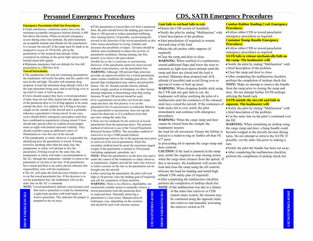
Emergency Parachutist Bail Out Procedures. • Under satisfactory conditions (static-line exit), the minimum acceptable emergency bailout altitude is 400 feet above the terrain. When an aircraft emergency occurs during static-line airdrops, the pilot maintains an acceptable attitude and altitude for the parachutists to evacuate the aircraft. If the jump must be made at an airspeed in excess of 150 KIAS, advise the parachutists of the airspeed and altitude. Order evacuation by turning on the green light and giving the briefed alarm bell signals. • Minimum emergency bail-out altitude for free-fall parachutists is 2,000 feet AGL. Towed Parachutist. • The jumpmaster will stop the remaining parachutists; the loadmaster will notify the pilot; and the copilot will turn on the red light. The pilot will maintain drop airspeed, at least the minimum drop altitude (AGL) for the type parachute being used, and avoid flying over or up wind of water or built up areas. • Crews should suspect they have a towed parachutist if static lines are not fully tucked into the upper corner of the paratroop door or if a D-bag appears to be stuck outside the door. It is unlikely for a D-bag to become caught on the outside of the aircraft and is a probable indicator a parachutist is being towed. In any case, crews should follow emergency procedures until they have confirmed no parachutist is being towed. Crews should take special effort to confirm towed jumper status at night with limited rearward visibility. They should consider using an additional source of illumination to view the rear of the aircraft. • The jumpmaster or safety observer is responsible for identifying how the parachutist is towed. If being towed by anything other than the static line, the jumpmaster or safety will attempt to free the parachutist. If being towed by the static line, the jumpmaster or safety will make a recommendation to the AC, through the loadmaster, whether to retrieve the parachutist or cut him or her free. If all parachutists have exited and there is no safety person onboard, this responsibility rests with the loadmaster. • The AC will make the final decision whether or not to cut the towed parachutist free. If the decision is to cut the parachutist free, the loadmaster will cut the static line on the AC’s command. NOTE: Towed parachutists indicate consciousness and
that reserve parachute is ready by maintaining a tight-body position with both hands on reserve parachute. This indicates the jumper is prepared to be cut away.
• If the parachutist is towed after exit from a paratroop door, the pilot should lower the landing gear and set flaps to 100 percent to reduce parachute buffeting. (See warning below.) If possible, avoid turning the aircraft in the direction of the towed parachutist as this often causes parachutist to swing violently and increases the possibility of injury. All turns should be shallow and coordinated to reduce the severity of parachutist oscillation. During training, the first priority is to retrieve the para-chutist whether he or she is conscious or unconscious. However, if the parachutist cannot be retrieved and indicates consciousness, cut the parachutist free. WARNING: Although 100 percent flaps selection provides an improved airflow for a towed parachutist, under certain conditions the landing gear down, 100 percent flap configuration may reduce aircraft perfor-mance. The AC should consider density altitude, aircraft weight, position in formation, or other factors deemed important in determining what flap setting between 50 and 100 percent should be used. • For a parachutist towed after exit from the cargo ramp and door, the first priority is to cut the parachutist free if consciousness is indicated. Retrieve if the parachutist is unconscious, does not sig-nal, cannot be observed, or if a condition exists that prevents cutting the static line. • There are two methods for the retrieval of towed parachutists from the paratroop doors. The primary method of retrieval is use of the Towed Parachutist Retrieval System (TPRS). The secondary method of retrieval is to rig a 5,000-pound tiedown strap/paratroop retriever bar in the paratroop door prior to retrieval of the towed parachutist. When the secondary method must be used, the maximum rigged weight of the parachutist is limited to 250 pounds (including equipment, parachute, etc.) NOTE: When the parachutist is in the door area and is under the control of the loadmaster or safety observer, or jumpmaster, slightly unwind the static line retriever to relieve tension on the line so the parachutist can be brought into the aircraft. • After retrieving the parachutist, the pilot will reset flaps to 50 percent, raise the landing gear (if required), and call for completion of drop checklist. WARNING: There is no effective, dependable, nor consistently reliable means to manually retrieve a towed parachutist from the paratroop door or ramp and door. Manually retrieving a parachutist is a last resort. Manual retrieval techniques vary, depending on the scenario, and should be used with extreme caution.
Gate fails to cut/load fails to exit. • Dearm the CDS switch (if installed). • Notify the pilot by stating “Malfunction” with a brief description of the problem. • Alert parachutists (if required) to remain forward/clear of the load. • Raise the aft anchor cable supports (if required). • Clear the ramp and door to close. WARNING: When notified of a malfunction, extend additional flaps and lower the nose to maintain as light nose down attitude until the ramp and door are closed and the load is secured. Maintain drop airspeed and AGL altitude (if possible) and avoid flying over or upwind of water or built up areas. WARNING: When dropping double stick using the CVR and one gate fails to cut, the loadmaster will delay notifying the pilot of a malfunction until the containers of the released stick have exited the aircraft. If the containers of both sticks fail to exit, notify the pilot immediately and continue with emergency procedures. WARNING: When the cargo ramp and door cannot be closed from the cockpit, the loadmaster secures the load for aft movement. Ensure the lifeline is locked to a tiedown ring no further aft than FS 677 prior to proceeding aft to operate the cargo ramp and door controls. CAUTION: If the load is jammed in the ramp area, notify the engineer to stop closing action when the cargo door releases from the uplock. If this is necessary, the loadmaster will secure the load and close the ramp using the aft controls. • Secure the load for landing and install high altitude CDS safety pins (if required). • After completing the malfunction checklist, perform the completion of airdrop check-list. NOTE: If the malfunction was due to a failure
of the static-line retriever or CDS remote timer system, the mission may be continued using the opposite static line retriever and manually activating the retriever switch at FS
Combat Rubber Raiding Craft Emergency Procedures. • Follow either CDS or towed parachutist emergency procedures as required. Container Ramp Bundle Emergency Procedures. • Follow either CDS or towed parachutist emergency procedures as required. SATB fails to release mechanically/falls on the ramp. The loadmaster will: • Notify the pilot by stating “Malfunction” with a brief description of the problem. • Clear the ramp and door to close. • After completing the malfunction checklist, perform the completion of airdrop check-list. NOTE: Make no attempt to remove the bundle from the ramp prior to closing the ramp and door. Do not attempt further SATB airdrops utilizing the bomb rack. SATB outside the aircraft and fails to separate. The loadmaster will: • Notify the pilot by stating “Malfunction” with a brief description of the problem. • Cut the static line on the pilot’s command over the DZ. WARNING: When simulating an airdrop using the cargo ramp and door, a hung bundle could become wedged in the aircraft elevator during turns. Do not attempt to retrieve the SATB. If possible, cut the static line prior to making a turn. • Notify the pilot the bundle has been cut away. • After completing the malfunction checklist, perform the completion of airdrop check-list.
Personnel Emergency Procedures CDS, SATB Emergency Procedures
DR
OP E
ME
RG
EN
CIE
S
DR
OP E
ME
RG
EN
CIE
S
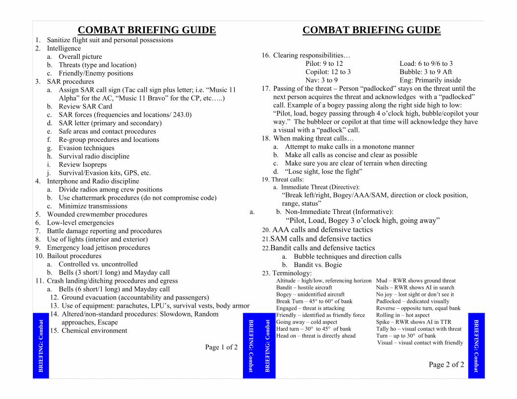
COMBAT BRIEFING GUIDE 1. Sanitize flight suit and personal possessions 2. Intelligence
a. Overall picture b. Threats (type and location) c. Friendly/Enemy positions
3. SAR procedures a. Assign SAR call sign (Tac call sign plus letter; i.e. “Music 11
Alpha” for the AC, “Music 11 Bravo” for the CP, etc…..) b. Review SAR Card c. SAR forces (frequencies and locations/ 243.0) d. SAR letter (primary and secondary) e. Safe areas and contact procedures f. Re-group procedures and locations g. Evasion techniques h. Survival radio discipline i. Review Isopreps j. Survival/Evasion kits, GPS, etc.
4. Interphone and Radio discipline a. Divide radios among crew positions b. Use chattermark procedures (do not compromise code) c. Minimize transmissions
5. Wounded crewmember procedures 6. Low-level emergencies 7. Battle damage reporting and procedures 8. Use of lights (interior and exterior) 9. Emergency load jettison procedures 10. Bailout procedures
a. Controlled vs. uncontrolled b. Bells (3 short/1 long) and Mayday call
11. Crash landing/ditching procedures and egress a. Bells (6 short/1 long) and Mayday call 12. Ground evacuation (accountability and passengers) 13. Use of equipment: parachutes, LPU’s, survival vests, body armor 14. Altered/non-standard procedures: Slowdown, Random
approaches, Escape 15. Chemical environment
Page 1 of 2
COMBAT BRIEFING GUIDE 16. Clearing responsibilities…
Pilot: 9 to 12 Load: 6 to 9/6 to 3 Copilot: 12 to 3 Bubble: 3 to 9 Aft Nav: 3 to 9 Eng: Primarily inside
17. Passing of the threat – Person “padlocked” stays on the threat until the next person acquires the threat and acknowledges with a “padlocked” call. Example of a bogey passing along the right side high to low: “Pilot, load, bogey passing through 4 o’clock high, bubble/copilot your way.” The bubbleer or copilot at that time will acknowledge they have a visual with a “padlock” call.
18. When making threat calls… a. Attempt to make calls in a monotone manner b. Make all calls as concise and clear as possible c. Make sure you are clear of terrain when directing d. “Lose sight, lose the fight”
19. Threat calls: a. Immediate Threat (Directive):
“Break left/right, Bogey/AAA/SAM, direction or clock position, range, status”
a. b. Non-Immediate Threat (Informative): “Pilot, Load, Bogey 3 o’clock high, going away”
20. AAA calls and defensive tactics 21.SAM calls and defensive tactics 22.Bandit calls and defensive tactics
a. Bubble techniques and direction calls b. Bandit vs. Bogie
23. Terminology: Altitude – high/low, referencing horizon Mud – RWR shows ground threat Bandit – hostile aircraft Nails – RWR shows AI in search Bogey – unidentified aircraft No joy – lost sight or don’t see it Break Turn – 45° to 60° of bank Padlocked – dedicated visually Engaged – threat is attacking Reverse – opposite turn, equal bank
Friendly – identified as friendly force Rolling in – hot aspect Going away – cold aspect Spike – RWR shows AI in TTR Hard turn – 30° to 45° of bank Tally ho – visual contact with threat
Head on – threat is directly ahead Turn – up to 30° of bank Visual – visual contact with friendly
Page 2 of 2
BR
IEFIN
G: C
ombat B
RIE
FIN
G: C
omba
t BR
IEFIN
G: C
ombat B
RIE
FIN
G: C
omba
t

General Formation Info Ground Ops: Min taxi interval: 4 eng =1 aircraft length (99’ 6”), 2 eng = 2 aircraft length If SKE will be used/backup - accomplish FCI check, inform lead of any SKE malfunctions ASAP On runway, lead on left, wing alternate sides, nose to tail clearance
Feed-on as briefed. Technique: time 15 seconds when lead crosses hold short, 2 crosses hold short on time, accelerate through turn, maintains runway center line on takeoff roll.
Takeoff: Min interval =15 sec, TECH: FI at -5 sec, don’t advance power until rolling Abort: Nav on interplane, CP on ATC, “Music Flight, #3s aborting, #3’s aborting, #3’s aborting” Airspeeds & As/Des Rates: Fly ↓ table or “As Briefed”. ↑ 15,000’ consider aircraft capabilities. Lead Should Fly: Below 10,000' 10,000' to 15,000' Above 15,000' Climb 180 KIAS 1,500 fpm 170 KIAS 1,500 fpm 160 KIAS 1,500 fpmAssembly 180 KIAS 170 KIAS 160 KIAS Cruise Normally 210 KIAS Normally 210 KIAS Normally 210 KIAS Enroute Altitude Change Enroute airspeed or as briefed 1,000 fpm or as briefed Descending Slowdown 140 KIAS 1,000 fpm As Briefed As Briefed DZ Escape 140 KIAS 1,000 fpm As Briefed As Briefed Airborne Aborts: Notify lead, turn away in safe direction, other aircraft in element move up. No-Drop: Lead notifies using FCI/interplane. Don’t radio individual no-drops to formation. Altitudes: Day VMC: 500’ AGL minimum. Exception: 300’ AGL on approved routes and one time use routes (as per 16.3.9.8.2) Modified Contour, use Visual references and Radar Altimeter. MSA/Night VMC/NVG: 5nm (3nm NVG) of centerline, ↑ of 500’+obst/spot ele, or 400’+1 contour Night VMC run-in: SD to Escape 3nm of CL; highest of: 500’ + obst/spot ele, or 400’ + 1 contour After SD: DZ in sight & remain so or +position known & terain clnc assured may ↓ to drop altitude IFR enroute: 5nm (10nm out-us) of centerline: highest obstacle/spot elevation +1000’ (2000 mts) round up to closest 100’. IFR on MTR in US will be computed MSA unless AP/1B requires higher IMC drop corridor: 3nm of CL: higher of 500’ +obst/spot elev, or 400’+1 contour (may segment) IMC drop: 3nm of CL: at a minimum, the highest of 500’ +obst/spot ele, or 400’ + 1 contour from DZ entry point to DZ exit point. If AFI 11-231 requires higher drop alt than above, use highest. ESA: 22nm of centerline: 1000’ +obs/spot ele (2000 mts). Can trim chart to 10 NM of route CL If next leg alt higher, climb & be at alt by the Turn Point, for decents wait until after the T Point Peacetime Route Restrictions: Thy shall not fly: (as per vol 3 16.3.9) Within 1 nm radius below 2000’ agl from sensitive areas: hospitals, fish hat, ostrich, poultry, etc Within 3 nm from Prohibited space & nuclear plants Through Restricted airspace (unless you have permission) or live fire/impact areas Below 1000’ AGL within 2000’ radius of cities/town magenta on TPC (1:500,000) Below 500’ unless host nation allows or route has been environmentally surveyed for 300’ ops SKE airdrop in uncontrolled space req NOTAM 48 hrs in advance- see V3 p203 Chart Requirements: CHUM out to 22nm, may trim to 10nm after ESA established Individual charts must have: TPs, IP, DZ, course line, course data, CHUM data, ESA Inadvertent Weather Penetration without SKE:
May need to modify due to terrain, geometry, airspace etc. Emergency procedure… may get violated so (if possible) stay VFR… Lead will give base alt (min ESA), heading, and airspeed (at min) Establish base speed & 1,000 fpm then turn 45° R/L for 2 min. Elem leads cont. straight Last element level @ base alt, each element +500’ higher than preceding Inadvertent Weather Penetration with SKE: Lead will give base alt (min ESA), and heading (at min) TECH: airspeed Climb @ cruise speed, 1,000 fpm, select SKE, set XTRK=1000’ When level, lead directs “Assume IFR interval”, wing -15Kts & drift back to 4,000/8,000’ Once in position, reset XTRK Lead may level formation below ESA if VMC Landing: 50% flap, GI and reverse/brakes as briefed desired interval Vis =20 sec, 15 sec minimum, SKE 6000’, 5000’ minimum. Thy shall not perform touch-and-go landings during formation recoveries.
Vis Formation Info Reasons for Formations: Size will be determined by user Mass on DZ Mutual Support Tac & Log support for Army Time efficient Easier to escort Types of Formations: will be determined by the nature of the threat Visual in-trail: 3 aircraft per element #2: 2,000’ back, right side, wing tip overlap out of wake turbulence #3: 4,000’ back, left side, wing tip overlap out of wake turbulence #4 (2nd element lead): 12,000’ back, centered Fluid trail: allows for freedom to evade, most flexibility, optimizes terrain masking, etc… 3 aircraft per element. Spacing will be pre-briefed (ie 2 2000’ to 6000’, 3 8000’ to 12000’) #2 & #3 move in arc from 3-9 o’clock position Line abreast: coastal/open terrain penetration or x-ing lines of communication - allows little flexibility during turns. 2 aircraft per element, wingmen (or elem leads) 4,000-24,000’ abeam lead Box: advantages of line abrest plus has mutual support. Two, 2-ship elements. Element leads fly abeam 4,000-24,000’ (line abreast) with wingmen in trail 2,000-24,000’. Modified V: shortens formation length, good for fighter escort. three 2-ship elements: within element 2,000-4,000’, 2nd element: 9,000’ in trail & right of lead, 3rd element: 18,000’ in trail & left. Inverted Vic: Used when you have a limited # of RVD’s. 3 aircraft elements. First two aircraft fly line abreast, with #3 in trail, spacing as briefed. (3 should be employed with Rear Vision Device) Extended Trail: Modified fluid trail- separation increased as briefed. Followers may have to use own navigation. Used when low visibility or terrain will not permit normal formation. Individual Ingress: Each aircraft navigates own way to join-up point/run-ins Departure & Assembly: After airfield boundary, wingmen adhere to ATC requirements Acceleration: May be based on radio call, time (start of lead’s TO roll), geo pt, DME, etc… Turns: TECH: after lead, #2 turns 5 sec, #3 turns 10 sec, #4 turns 30 sec VIS Rejoin: 500’ above/below formation until formation in sight & cleared to join. Orbit: 1000’ above orbit alt- must be VFR before orbit pt Slow to 180 KIAS (or as briefed) at orbit pt. At 1st turn outbound, descend to 500’ above orbit until form in sight or turn inbound Altitude/Airspeeds: Night VFR: Lead announces speed changes >15kts. Day VFR altitude: Lead follows terrain w/ref to Radar Altimeter. Wing maintain position relative to lead while referencing terrain & Radar Alt. Night VMC: Lead follows Pressure Altimeter. Wing reference lead & monitor PA. (a wingman 2000’ in trail & 175’ low can impact a light weight jumper) Slowdown: elements slow at pre-briefed point to compress formation. At night (unless tactically unsound)include visual/aural signal. Throttles 1,000 inch/lbs, flaps 50%, climb/descend @ 140KIAS. At drop alt, slow to drop airspeed. Airdrop Procedures: each element flies own approach until red light. Wingmen main position, releases on own CARP. Crosswind >3°, wing maintains same ground track as leader. CDS: Min spacing for CDS=6,000’ (12,000’ if IMC) Each aircraft flies to its own CARP. DZ Escape: At red light & load clear, accelerate to 140KIAS & climb/descend as required. Elements will accelerate at pre-briefed time/location/radio call @ 900° TIT Recovery: Complete Decent Checks prior to pattern entry or initial. Downwind: 200KIAS 1,000’ AGL or pattern alt (highest) Wing fly same track as lead, stack slightly, put leads horiz stab ½ up vert stab Lead break ½nm past app end w/45° bank FI, ~10 sec after dep end Wait 10-12 sec for 20 sec interval Level turn until 140KIAS, slow to App on final Roll out >300’ & >¼ mile from runway
Overhead: 200KIAS 1,500’ AGL or pattern alt (highest) Wing fly same track as lead, stack slightly, break 3-5 sec after lead Lead break app end, wing break no earlier than lead, 45° bank, FI, maintain 150KIAS Want 1600-1800’ spacing on downwind, have CP call 160KIAS & 20° to rollout Final turn 12-14 sec for 20 sec interval, 140KIAS until final Roll out >300’ & >¼ mile from runway Landing: Land on centerline, 50% flaps. Ground idle, brakes/Reverse as briefed. Clear at end. Desired interval 20 sec (15 Min) consider more for adverse conditions.
FOR
MA
TIO
N FO
RM
AT
ION
V
IS FOR
MA
TIO
N V
IS F
OR
MA
TIO
N
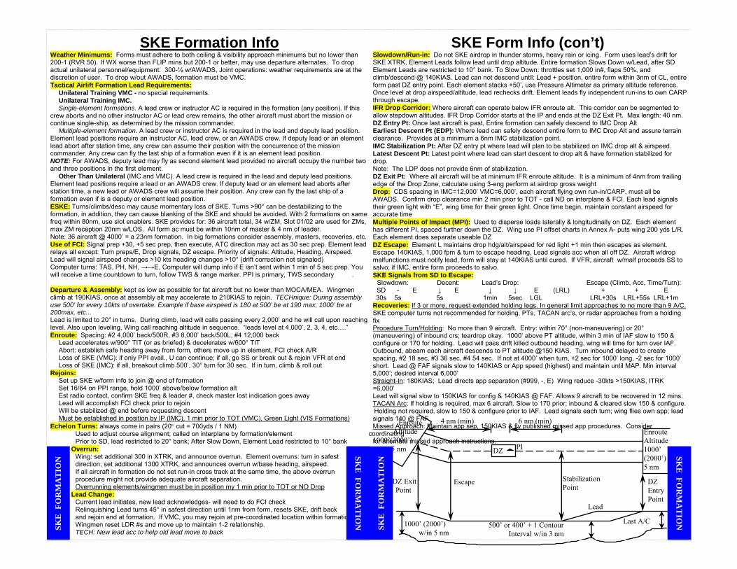
SKE Formation Info Weather Minimums: Forms must adhere to both ceiling & visibility approach minimums but no lower than 200-1 (RVR 50). If WX worse than FLIP mins but 200-1 or better, may use departure alternates. To drop actual unilateral personnel/equipment: 300-½ w/AWADS, Joint operations: weather requirements are at the discretion of user. To drop w/out AWADS, formation must be VMC. Tactical Airlift Formation Lead Requirements: Unilateral Training VMC - no special requirements. Unilateral Training IMC. Single-element formations. A lead crew or instructor AC is required in the formation (any position). If this crew aborts and no other instructor AC or lead crew remains, the other aircraft must abort the mission or continue single-ship, as determined by the mission commander. Multiple-element formation. A lead crew or instructor AC is required in the lead and deputy lead position. Element lead positions require an instructor AC, lead crew, or an AWADS crew. If deputy lead or an element lead abort after station time, any crew can assume their position with the concurrence of the mission commander. Any crew can fly the last ship of a formation even if it is an element lead position. NOTE: For AWADS, deputy lead may fly as second element lead provided no aircraft occupy the number two and three positions in the first element. Other Than Unilateral (IMC and VMC). A lead crew is required in the lead and deputy lead positions. Element lead positions require a lead or an AWADS crew. If deputy lead or an element lead aborts after station time, a new lead or AWADS crew will assume their position. Any crew can fly the last ship of a formation even if is a deputy or element lead position. ESKE: Turns/climbs/desc may cause momentary loss of SKE. Turns >90° can be destabilizing to the formation, in addition, they can cause blanking of the SKE and should be avoided. With 2 formations on same freq within 80nm, use slot enablers. SKE provides for: 36 aircraft total, 34 w/ZM, Slot 01/02 are used for ZMs, max ZM reception 20nm w/LOS. All form ac must be within 10nm of master & 4 nm of leader. Note: 36 aircraft @ 4000’ = a 23nm formation. In big formations consider assembly, masters, recoveries, etc. Use of FCI: Signal prep +30, +5 sec prep, then execute, ATC direction may act as 30 sec prep. Element lead relays all except: Turn preps/E, Drop signals, DZ escape. Priority of signals: Altitude, Heading, Airspeed. Lead will signal airspeed changes >10 kts heading changes >10° (drift correction not signaled) Computer turns: TAS, PH, NH, →→E, Computer will dump info if E isn’t sent within 1 min of 5 sec prep. You will receive a time countdown to turn, follow TWS & range marker. PPI is primary, TWS secondary . Departure & Assembly: kept as low as possible for fat aircraft but no lower than MOCA/MEA. Wingmen climb at 190KIAS, once at assembly alt may accelerate to 210KIAS to rejoin. TECHnique: During assembly use 500’ for every 10kts of overtake. Example if base airspeed is 180 at 500’ be at 190 max, 1000’ be at 200max, etc... Lead is limited to 20° in turns. During climb, lead will calls passing every 2,000’ and he will call upon reaching level. Also upon leveling, Wing call reaching altitude in sequence. “leads level at 4,000’, 2, 3, 4, etc….” Enroute: Spacing: #2 4,000’ back/500R, #3 8,000’ back/500L, #4 12,000 back Lead accelerates w/900° TIT (or as briefed) & decelerates w/600° TIT Abort: establish safe heading away from form, others move up in element, FCI check A/R Loss of SKE (VMC): if only PPI avail., U can continue; if all, go SS or break out & rejoin VFR at end Loss of SKE (IMC): if all, breakout climb 500’, 30° turn for 30 sec. If in turn, climb & roll out Rejoins: Set up SKE w/form info to join @ end of formation Set 16/64 on PPI range, hold 1000’ above/below formation alt Est radio contact, confirm SKE freq & leader #, check master lost indication goes away Lead will accomplish FCI check prior to rejoin Will be stabilized @ end before requesting descent Must be established in position by IP (IMC), 1 min prior to TOT (VMC), Green Light (VIS Formations) Echelon Turns: always come in pairs (20° cut = 700yds / 1 NM) Used to adjust course alignment; called on interplane by formation/element Prior to SD, lead restricted to 20° bank; After Slow Down, Element Lead restricted to 10° bank
Overrun: Wing: set additional 300 in XTRK, and announce overrun. Element overruns: turn in safest direction, set additional 1300 XTRK, and announces overrun w/base heading, airspeed. If all aircraft in formation do not set run-in cross track at the same time, the above overrun procedure might not provide adequate aircraft separation. Overrunning elements/wingmen must be in position my 1 min prior to TOT or NO Drop
Lead Change: Current lead initiates, new lead acknowledges- will need to do FCI check Relinquishing Lead turns 45° in safest direction until 1nm from form, resets SKE, drift back and rejoin end at formation. If VMC, you may rejoin at pre-coordinated location within formation. Wingmen reset LDR #s and move up to maintain 1-2 relationship. TECH: New lead acc to help old lead move to back
SKE Form Info (con’t) Slowdown/Run-in: Do not SKE airdrop in thunder storms, heavy rain or icing. Form uses lead’s drift for SKE XTRK, Element Leads follow lead until drop altitude. Entire formation Slows Down w/Lead, after SD Element Leads are restricted to 10° bank. To Slow Down: throttles set 1,000 in#, flaps 50%, and climb/descend @ 140KIAS. Lead can not descend until: Lead + position, entire form within 3nm of CL, entire form past DZ entry point. Each element stacks +50’, use Pressure Altimeter as primary altitude reference. Once level at drop airspeed/altitude, lead rechecks drift. Element leads fly independent run-ins to own CARP through escape. IFR Drop Corridor: Where aircraft can operate below IFR enroute alt. This corridor can be segmented to allow stepdown altitudes. IFR Drop Corridor starts at the IP and ends at the DZ Exit Pt. Max length: 40 nm. DZ Entry Pt: Once last aircraft is past, Entire formation can safely descend to IMC Drop Alt Earliest Descent Pt (EDP): Where lead can safely descend entire form to IMC Drop Alt and assure terrain clearance. Provides at a minimum a 6nm IMC stabilization point. IMC Stabilization Pt: After DZ entry pt where lead will plan to be stabilized on IMC drop alt & airspeed. Latest Descent Pt: Latest point where lead can start descent to drop alt & have formation stabilized for drop. Note: The LDP does not provide 6nm of stabilization. DZ Exit Pt: Where all aircraft will be at minimum IFR enroute altitude. It is a minimum of 4nm from trailing edge of the Drop Zone, calculate using 3-eng perform at airdrop gross weight Drop: CDS spacing in IMC=12,000’ VMC=6,000’, each aircraft flying own run-in/CARP, must all be AWADS. Confirm drop clearance min 2 min prior to TOT - call ND on interplane & FCI. Each lead signals their green light with “E”, wing time for their green light. Once time begin, maintain constant airspeed for accurate time Multiple Points of Impact (MPI): Used to disperse loads laterally & longitudinally on DZ. Each element has different PI, spaced further down the DZ. Wing use PI offset charts in Annex A- puts wing 200 yds L/R. Each element does separate useable DZ DZ Escape: Element L maintains drop hdg/alt/airspeed for red light +1 min then escapes as element. Escape 140KIAS, 1,000 fpm & turn to escape heading, Lead signals acc when all off DZ. Aircraft w/drop malfunctions must notify lead, form will stay at 140KIAS until cured. If VFR, aircraft w/malf proceeds SS to salvo; if IMC, entire form proceeds to salvo. SKE Signals from SD to Escape: Slowdown: Decent: Lead’s Drop: Escape (Climb, Acc, Time/Turn): SD - E ↓ E ↓ ↓ E (LRL) + + E 30s 5s 5s 1min 5sec LGL LRL+30s LRL+55s LRL+1m Recoveries: If 3 or more, request extended holding legs. In general limit approaches to no more than 9 A/C. SKE computer turns not recommended for holding, PTs, TACAN arc’s, or radar approaches from a holding fix Procedure Turn/Holding: No more than 9 aircraft. Entry: within 70° (non-maneuvering) or 20° (maneuvering) of inbound crs; teardrop okay. 1000’ above PT altitude, within 3 min of IAF slow to 150 & configure or 170 for holding. Lead will pass drift killed outbound heading, wing will time for turn over IAF. Outbound, abeam each aircraft descends to PT altitude @150 KIAS. Turn inbound delayed to create spacing, #2 18 sec, #3 36 sec, #4 54 sec. If not at 4000’ when turn, +2 sec for 1000’ long, -2 sec for 1000’ short. Lead @ FAF signals slow to 140KIAS or App speed (highest) and maintain until MAP. Min interval 5,000’; desired interval 6,000’ Straight-In: 180KIAS; Lead directs app separation (#999, -, E) Wing reduce -30kts >150KIAS, ITRK =6,000’ Lead will signal slow to 150KIAS for config & 140KIAS @ FAF. Allows 9 aircraft to be recovered in 12 mins. TACAN Arc: If holding is required, max 6 aircraft. Slow to 170 prior; inbound & cleared slow 150 & configure.
Holding not required, slow to 150 & configure prior to IAF. Lead signals each turn; wing flies own app; lead signals 140 @ FAF Missed Approach: Maintain app sep, 150KIAS & fly published missed app procedures. Consider coordinating for alternate missed approach instructions.
Enroute Altitude1000’ (2000’) 5 nm
Last A/C
DZ ExitPoint
Enroute Altitude 1000’(2000’) 5 nm DZ
Lead
DZ EntryPoint
StabilizationPoint
Escape
500’ or 400’ + 1 ContourInterval w/in 3 nm
1000’ (2000’) w/in 5 nm
6 nm (min)4 nm (min)
PI
SKE
FO
RM
AT
ION
SKE
FOR
MA
TIO
N SK
E F
OR
MA
TIO
N SK
E FO
RM
AT
ION

MICROWAVE LANDING SYSTEM
MLS Self-Test (Automatic if power interrupted 3 seconds) 1. Autopilot - Disengaged 2. Flight Director Switch-
NORMAL 3. Nav Selectors - MLS 4. HSI Course Window -
Airplane Heading 5. Self Test - Activated MLS Approach Guide 1. MLS and TAC – ON 2. Tune both MLS’s –
Desired Channel 3. TACANs - Tune
Required Frequncy. Tune TACANs manually, don’t use the reference library as per -1 Warning p 4-68
4. MLS 1-2 Page –AUTO Mode Selected (default) 5. MLS 1-2 Page – NON-COMP/COMP Mode (as require)
a. Select COMP for COMPUTED MLS Approach (Select COMP only if approach specifically states to do so)
b. Select NON-COMP for MLS Approach (default) 6. MLS 2-2 Page - Verify 4 Letter Identifier (Mxxx) 7. MLS 2-2 Page - Verify OVRD Not Selected 8. Nav Selectors – MLS
(ensure TAC not selected on either Nav Selector) 9. HSI Course Window – Approach Course 10. MLS 2-2 Page – Confirm TAC on MLS frequency 11. Flight Director Switch – NORMAL 12. Fly the Approach
a. MLS Course - Intercept b. Ident on MLS 2-2 page - Monitor
14. Missed Approach – Retune TACAN as required
ELECTRICAL SYSTEM PILOTS COPILOT “LRAFBI” “MRSEAL” LH AC ESS AC MAIN AC RH AC #1 Main FBP #2 Main FBP #3 Main FBP #4 Main FBP Fwd LH Ext FBP Aux Hyd Pmp Aux FBP Fwd RH Ext FBP Galley Aux Feath Mtr Aft Ext FBP Anti-Ice NESA Heat Suct Bst Pmp Radar Underfloor Heat Trim SKE All of the “Crew Comfort” Compas/HDG Indications “Dump Bus” primary AC are SCNS, Antiskid, GCAS 115/200 Volt Autopilot, Syncrophaser 400 Cycle 3 Phase CP Instruments AC Instruments and Engine Fuel Control Flight Directors Torquemeter Powered by: Inverter from ESS ADIs TIT DC & also ESS AC Powered by: Fuel Flow Has auto-switching from Inverter from Isol DC & LOX Qty Ess DC to ESS AC Txfrmr from Ess AC Fuel Qty 115 V / 400 cycle / single phase 115 Volt 400 Cycle #1 Txfrmr #2 Txfrmr 3 Phase “1 FEB 34” Anti-Skid Test Fuel Press 1&2 Oil Press EmerBrake Press “122-2-122” Boost Hyd Press 2 2 2 1 2 3&4 Oil Press Both are 26V 1 2 Battery Isolated Essential DC Main DC “FAAJIVEEES” GTC Start/Cont Valves Lights Fire Ext. ATM Control Oil Temp Flap Ctrl Valve Alarm Bell Interphone Oil Qty Norm Brakes AC Ext Pwr UHF (Man) Oil Cool Flaps SKE Jump Lights Gen Control Oil Low Qty Lts Static Line Ret Isol DC Bus Bus Off Ind SCNS Winch on Bat Light CP Pitot Ht Fire Detect Anchor Cable Voltmeter (Bat) CP Flood Lts Ignition Control Air Def Doors
Emer Depress Bus Tie Control for: Emer Lt Ext Aux Hyd Pump Aft Fues Jct Box ELT SuctBst Pump Ramp & ADS SKE Batt Aux Feather Moto Tab & Flap Ind Emer Elev Trim More Lights
ML
S LH AC
AC Inst & Eng Fuel Cntrl
RH AC
FUSES for
gyros & press ind.
Ess AC&
Battery
SKE
Ess AC & Isol 9 Comb Cbs & Trim
Ess DC
Start & Ign
Control
Ess DC
Eng Inst
Ess DCAircrft Lndg Gear Cntrl
Main DC
Lights SKE & Flaps
Radio Circuits
Main AC
SKE
Upper Main AC Dist Panel Curr Limiters for Main,
RH, LH AC &AC, 9 Combat wired CB for Ess
AC
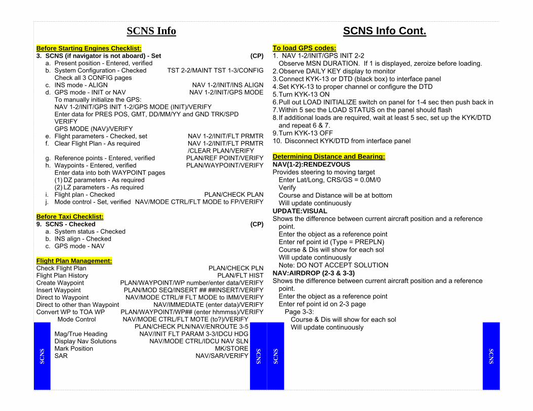
SCNS Info
Before Starting Engines Checklist: 3. SCNS (if navigator is not aboard) - Set (CP) a. Present position - Entered, verified b. System Configuration - Checked TST 2-2/MAINT TST 1-3/CONFIG Check all 3 CONFIG pages c. INS mode - ALIGN NAV 1-2/INIT/INS ALIGN d. GPS mode - INIT or NAV NAV 1-2/INIT/GPS MODE To manually initialize the GPS: NAV 1-2/INIT/GPS INIT 1-2/GPS MODE (INIT)/VERIFY Enter data for PRES POS, GMT, DD/MM/YY and GND TRK/SPD VERIFY GPS MODE (NAV)/VERIFY e. Flight parameters - Checked, set NAV 1-2/INIT/FLT PRMTR f. Clear Flight Plan - As required NAV 1-2/INIT/FLT PRMTR /CLEAR PLAN/VERIFY g. Reference points - Entered, verified PLAN/REF POINT/VERIFY h. Waypoints - Entered, verified PLAN/WAYPOINT/VERIFY Enter data into both WAYPOINT pages (1) DZ parameters - As required (2) LZ parameters - As required i. Flight plan - Checked PLAN/CHECK PLAN j. Mode control - Set, verified NAV/MODE CTRL/FLT MODE to FP/VERIFY Before Taxi Checklist: 9. SCNS - Checked (CP) a. System status - Checked b. INS align - Checked c. GPS mode - NAV Flight Plan Management: Check Flight Plan PLAN/CHECK PLN Flight Plan History PLAN/FLT HIST Create Waypoint PLAN/WAYPOINT/WP number/enter data/VERIFY Insert Waypoint PLAN/MOD SEQ/INSERT ## ##INSERT/VERIFY Direct to Waypoint NAV/MODE CTRL/# FLT MODE to IMM/VERIFY Direct to other than Waypoint NAV/IMMEDIATE (enter data)/VERIFY Convert WP to TOA WP PLAN/WAYPOINT/WP## (enter hhmmss)/VERIFY
Mode Control NAV/MODE CTRL/FLT MOTE (to?)/VERIFY PLAN/CHECK PLN/NAV/ENROUTE 3-5
Mag/True Heading NAV/INIT FLT PARAM 3-3/IDCU HDG Display Nav Solutions NAV/MODE CTRL/IDCU NAV SLN Mark Position MK/STORE SAR NAV/SAR/VERIFY
SCNS Info Cont. To load GPS codes: 1. NAV 1-2/INIT/GPS INIT 2-2 Observe MSN DURATION. If 1 is displayed, zeroize before loading. 2. Observe DAILY KEY display to monitor 3. Connect KYK-13 or DTD (black box) to interface panel 4. Set KYK-13 to proper channel or configure the DTD 5. Turn KYK-13 ON 6. Pull out LOAD INITIALIZE switch on panel for 1-4 sec then push back in 7. Within 5 sec the LOAD STATUS on the panel should flash 8. If additional loads are required, wait at least 5 sec, set up the KYK/DTD
and repeat 6 & 7. 9. Turn KYK-13 OFF 10. Disconnect KYK/DTD from interface panel Determining Distance and Bearing: NAV(1-2):RENDEZVOUS Provides steering to moving target Enter Lat/Long, CRS/GS = 0.0M/0 Verify Course and Distance will be at bottom Will update continuously UPDATE:VISUAL Shows the difference between current aircraft position and a reference
point. Enter the object as a reference point Enter ref point id (Type = PREPLN) Course & Dis will show for each sol Will update continuously Note: DO NOT ACCEPT SOLUTION NAV:AIRDROP (2-3 & 3-3) Shows the difference between current aircraft position and a reference
point. Enter the object as a reference point Enter ref point id on 2-3 page
Page 3-3: Course & Dis will show for each sol Will update continuously
SCN
S SCN
S SCN
S SCN
S

Cargo Compartment Info Cargo Area Cargo floor (from 245 to 737): 41’ x 10’ 3” Ramp: 10’ x 10’ Overhead length: 50’ Height: 9’ (can +1” by removing litter mounting brackets in wheel well) 74 litters with 2 attendants or 70 with 6 92 ground troops (90 w/2 LM) 64 paratroopers w/equipment Overwater limited to 80 people total Ramp slope: open=11.5° closed=159° Tie Down Fittings 5,000#: Ramp floor and cargo comp sidewalls Ramp: 33 fittings Sidewalls: 11 on each wall 10,000#: Cargo floor & rings on dual rails 7 columns- 25 per column, 175 total 25,000#: Cargo floor: 5 each side under dual rails, 2 at FS 737 12 sockets- only 2 usable w/dual rails, plugged when not in use Strength Areas- Heaviest load normally placed in center of aircraft Floor load: max 50 psi (Exception: internal tire pressure <100 psi) Treadways (x2)- 35” wide, 15” from centerline Max inflight weight: 13000# per axel Max weight C,D & K: 6,000# per axel Ramp (L&M comp) max: 2,500# per axel Exception: if single axel is only thing on ramp, max=3,500# Max inflight weight off treadways: 5,000# per axel, ramp: 1,200# per axel Ramp weight max 5,000# including dual rails w/Dual rails, max load=4,664# w/out rollers, max load=4,824# Max tongue loads: floor=2,000# ramp=450# Truck Loading Ramps- 3’ long x 26” wide Max 25,000# per pair Attached to ramp w/hooks & latches Auxiliary Ground Loading Ramps- 66” long x 21” wide Max 13,000# per axel Hook onto ramp but don’t lock Bridge Plates- Used between ramp & truck bed, K loader or flat bed Max 7,500# per plate, ramp must be supported Ramp Support (Milk stool)- May not use chocks… Supports aft end of ramp when horizontal Required when more than 2,000# moved across the ramp Ramp must exert positive pressure against support ADS arms may have to be disconnected May use layers of plywood (18” square) to raise ramp level
Tiedown Equipment 5,000# (GGU-1B)- 20’ nylon webbing 10,000# (MB-1, CGU-3/E)- 34 chains & devices carried 25,000# (MB-2, CGU-4/E)- 6 chains/devices carried for gear tiedown Wheeled Pry Bar- “J” Bar or MA-1 -must have hard rubber/polyurethane wheels Outside =5,000# per bar, In cargo comp =2,000 per bar Snatch Blocks- two ¾” cable blocks per aircraft Cannot be used with any aircraft cargo winch
CA
RG
O C
OM
PAR
T C
AR
GO
CO
MPA
RT
T
UR
N &
BU
RN
TU
RN
& B
UR
N
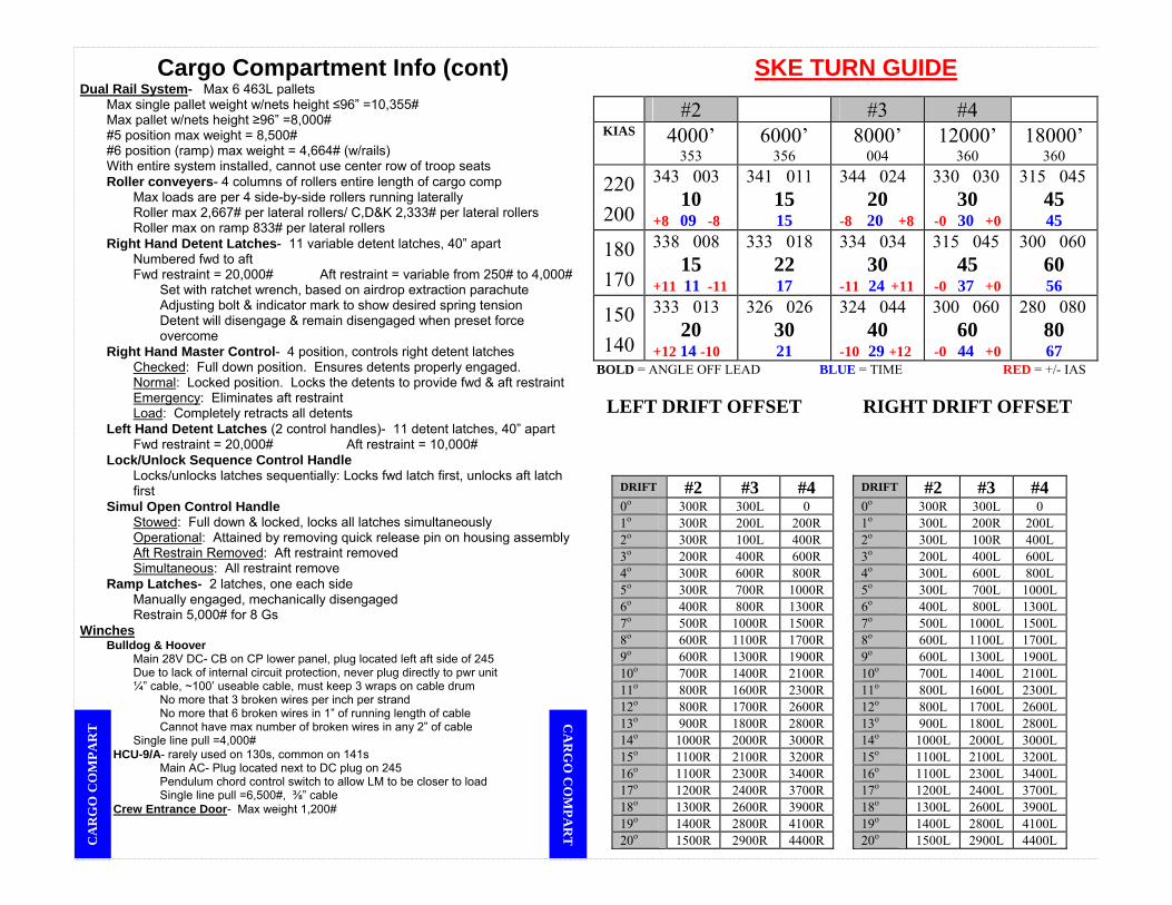
Cargo Compartment Info (cont) Dual Rail System- Max 6 463L pallets Max single pallet weight w/nets height ≤96” =10,355# Max pallet w/nets height ≥96” =8,000# #5 position max weight = 8,500# #6 position (ramp) max weight = 4,664# (w/rails) With entire system installed, cannot use center row of troop seats Roller conveyers- 4 columns of rollers entire length of cargo comp Max loads are per 4 side-by-side rollers running laterally Roller max 2,667# per lateral rollers/ C,D&K 2,333# per lateral rollers Roller max on ramp 833# per lateral rollers Right Hand Detent Latches- 11 variable detent latches, 40” apart Numbered fwd to aft Fwd restraint = 20,000# Aft restraint = variable from 250# to 4,000# Set with ratchet wrench, based on airdrop extraction parachute Adjusting bolt & indicator mark to show desired spring tension
Detent will disengage & remain disengaged when preset force overcome
Right Hand Master Control- 4 position, controls right detent latches Checked: Full down position. Ensures detents properly engaged. Normal: Locked position. Locks the detents to provide fwd & aft restraint Emergency: Eliminates aft restraint Load: Completely retracts all detents Left Hand Detent Latches (2 control handles)- 11 detent latches, 40” apart Fwd restraint = 20,000# Aft restraint = 10,000# Lock/Unlock Sequence Control Handle Locks/unlocks latches sequentially: Locks fwd latch first, unlocks aft latch first Simul Open Control Handle Stowed: Full down & locked, locks all latches simultaneously Operational: Attained by removing quick release pin on housing assembly Aft Restrain Removed: Aft restraint removed Simultaneous: All restraint remove Ramp Latches- 2 latches, one each side Manually engaged, mechanically disengaged Restrain 5,000# for 8 Gs Winches Bulldog & Hoover Main 28V DC- CB on CP lower panel, plug located left aft side of 245 Due to lack of internal circuit protection, never plug directly to pwr unit ¼” cable, ~100’ useable cable, must keep 3 wraps on cable drum No more that 3 broken wires per inch per strand No more that 6 broken wires in 1” of running length of cable Cannot have max number of broken wires in any 2” of cable Single line pull =4,000#
HCU-9/A- rarely used on 130s, common on 141s Main AC- Plug located next to DC plug on 245 Pendulum chord control switch to allow LM to be closer to load Single line pull =6,500#, ⅜” cable Crew Entrance Door- Max weight 1,200#
SKE TURN GUIDE
#2 #3 #4 KIAS 4000’
353 6000’
356 8000’
004 12000’
360 18000’
360
220200
343 003 10
+8 09 -8
341 011 15 15
344 024 20
-8 20 +8
330 030 30
-0 30 +0
315 045 45 45
180170
338 008 15
+11 11 -11
333 018 22 17
334 034 30
-11 24 +11
315 045 45
-0 37 +0
300 060 60 56
150140
333 013 20
+12 14 -10
326 026 30 21
324 044 40
-10 29 +12
300 060 60
-0 44 +0
280 080 80 67
BOLD = ANGLE OFF LEAD BLUE = TIME RED = +/- IAS
LEFT DRIFT OFFSET RIGHT DRIFT OFFSET
DRIFT #2 #3 #4 DRIFT #2 #3 #4 0o 300R 300L 0 0o 300R 300L 0 1o 300R 200L 200R 1o 300L 200R 200L 2o 300R 100L 400R 2o 300L 100R 400L 3o 200R 400R 600R 3o 200L 400L 600L 4o 300R 600R 800R 4o 300L 600L 800L 5o 300R 700R 1000R 5o 300L 700L 1000L 6o 400R 800R 1300R 6o 400L 800L 1300L 7o 500R 1000R 1500R 7o 500L 1000L 1500L 8o 600R 1100R 1700R 8o 600L 1100L 1700L 9o 600R 1300R 1900R 9o 600L 1300L 1900L 10o 700R 1400R 2100R 10o 700L 1400L 2100L 11o 800R 1600R 2300R 11o 800L 1600L 2300L 12o 800R 1700R 2600R 12o 800L 1700L 2600L 13o 900R 1800R 2800R 13o 900L 1800L 2800L 14o 1000R 2000R 3000R 14o 1000L 2000L 3000L 15o 1100R 2100R 3200R 15o 1100L 2100L 3200L 16o 1100R 2300R 3400R 16o 1100L 2300L 3400L 17o 1200R 2400R 3700R 17o 1200L 2400L 3700L 18o 1300R 2600R 3900R 18o 1300L 2600L 3900L 19o 1400R 2800R 4100R 19o 1400L 2800L 4100L 20o 1500R 2900R 4400R 20o 1500L 2900L 4400L C
AR
GO
CO
MPA
RT
CA
RG
O C
OM
PAR
T

WINDMILL TAXI START BRIEFING GUIDE 1. PREPARATION a. After Landing Checklist (if Req’d) b. Ground Stop Downwind Engine (simulated) c. Review Dash-1 (Notes, Warnings, Cautions) 2. BRIEFING a. Pilot/Co-Pilot Call: “Off Nosewheel Steering” “90 kts” “100 kts” “4000′ Remaining” b. Engineer Call: “Rotation” “Light Off” “40 %” “On Speed” c. Any Crewmember “Reject” (as Req’d) (1) Less than 40% - Feather Starting Engine First (2) Greater Than 40% - Allow Starting Engine to Run (3) Starting Engine Malfunction - Feather 3. EXECUTION a. Before Takeoff Checklist b. Lineup Checklist c. Windmilling Engine Throttle - Flight Idle d. Assymetrical Throttle - Start of Torque Curve e. Symmetrical Throttles - Max Power f. Rudder - Toward Good Engine - Release Brakes g. Rudder Effectiveness - Off Nosewheel Steering h. Throttle on Assymetric Engine - Advance as Req’d i. 90 kts - Retard Throttles to Maintain 100 kts j. 40% or 4,000′ Remaining - Throttles Gnd Idle k. Reverse Symmetrical On-Speed Engines as Req’d l. Starting Engines Checklist
Max Effort Takeoff Guide Reasons: Rwy < MFL normal or CFL, whichever is longer; Rwy width < 80’(must be >
60’); or Vmcg > Charted refusal speed that is less than Take Off speed A. Review TOLD 1. Takeoff speed: Vmca vs Vmeto Based on: WX, rwy length, TOLD, Vmeto, Vmcg, Vmca, airfield survey, Review of hazards, obstructions, terrain both laterally and along climb path 2. Decision speed: refusal, Vto. 3. Obstacle Clearance: Vmca + 10 vs Max Effort Obst Clnc 4. Flap retraction: Obstacle clearance speed + 10 5. Ground run/(Stop and go distance) 6. Min runway: Peacetime 3000’, Contingency MFLMETO 7. Winds in recommended zone 8. Gross Weight/Bleed air valves B. Crew Coordination 1. Acc time check required if Vto > Vr 2. As brakes released: Pilot states “HACK”, Nav states “TIMING” 3. At acceleration time: Nav: states “TIME”, Co: if check failed (-3Kts) “REJECT TIME” 4. At decision speed: Copilot states “GO” (Guard the yoke) 5. At takeoff speed: Copilot states “ROTATE” 6. Signals for Gear/Flap retraction C. Emergency Actions During Takeoff 1. Aborted Takeoff a. Prop malfunctions b. Engine malfunctions: Reject for negative torque (power loss) only c. System malfunctions: Continue takeoff d. Malfunctions between Vr and Vto e. Hot brakes if high speed abort/Loss of normal brakes 2. Fuel Dumping/service ceilings 3. Emergency Return D. Departure Procedure 1. Nav aids 2. Radar Altimeter: 50’ vs emergency return 3. Flight director, SID 4. Hazardous terrain/obstacles laterally and in climb path 5. Weather
6. Threats
BR
IEF:
Win
dmill
Sta
rt B
RIE
F: Windm
ill Start BR
IEF:
Max
Eff
ort B
RIE
F: Max E
ffort
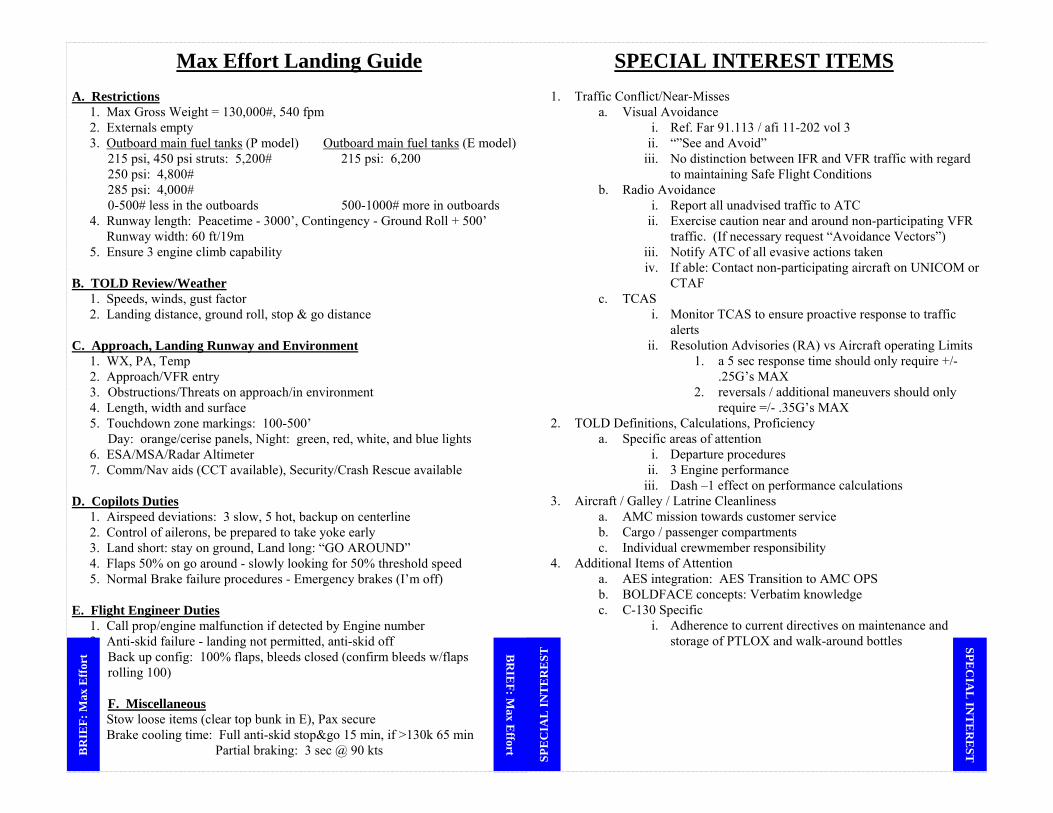
Max Effort Landing Guide A. Restrictions 1. Max Gross Weight = 130,000#, 540 fpm 2. Externals empty 3. Outboard main fuel tanks (P model) Outboard main fuel tanks (E model) 215 psi, 450 psi struts: 5,200# 215 psi: 6,200 250 psi: 4,800# 285 psi: 4,000# 0-500# less in the outboards 500-1000# more in outboards 4. Runway length: Peacetime - 3000’, Contingency - Ground Roll + 500’ Runway width: 60 ft/19m 5. Ensure 3 engine climb capability B. TOLD Review/Weather 1. Speeds, winds, gust factor 2. Landing distance, ground roll, stop & go distance C. Approach, Landing Runway and Environment 1. WX, PA, Temp 2. Approach/VFR entry 3. Obstructions/Threats on approach/in environment 4. Length, width and surface 5. Touchdown zone markings: 100-500’ Day: orange/cerise panels, Night: green, red, white, and blue lights 6. ESA/MSA/Radar Altimeter 7. Comm/Nav aids (CCT available), Security/Crash Rescue available D. Copilots Duties 1. Airspeed deviations: 3 slow, 5 hot, backup on centerline 2. Control of ailerons, be prepared to take yoke early 3. Land short: stay on ground, Land long: “GO AROUND” 4. Flaps 50% on go around - slowly looking for 50% threshold speed 5. Normal Brake failure procedures - Emergency brakes (I’m off) E. Flight Engineer Duties 1. Call prop/engine malfunction if detected by Engine number 2. Anti-skid failure - landing not permitted, anti-skid off
3. Back up config: 100% flaps, bleeds closed (confirm bleeds w/flaps 4. rolling 100)
F. Miscellaneous
1. Stow loose items (clear top bunk in E), Pax secure 2. Brake cooling time: Full anti-skid stop&go 15 min, if >130k 65 min
Partial braking: 3 sec @ 90 kts
SPECIAL INTEREST ITEMS
1. Traffic Conflict/Near-Misses a. Visual Avoidance
i. Ref. Far 91.113 / afi 11-202 vol 3 ii. “”See and Avoid”
iii. No distinction between IFR and VFR traffic with regard to maintaining Safe Flight Conditions
b. Radio Avoidance i. Report all unadvised traffic to ATC
ii. Exercise caution near and around non-participating VFR traffic. (If necessary request “Avoidance Vectors”)
iii. Notify ATC of all evasive actions taken iv. If able: Contact non-participating aircraft on UNICOM or
CTAF c. TCAS
i. Monitor TCAS to ensure proactive response to traffic alerts
ii. Resolution Advisories (RA) vs Aircraft operating Limits 1. a 5 sec response time should only require +/-
.25G’s MAX 2. reversals / additional maneuvers should only
require =/- .35G’s MAX 2. TOLD Definitions, Calculations, Proficiency
a. Specific areas of attention i. Departure procedures
ii. 3 Engine performance iii. Dash –1 effect on performance calculations
3. Aircraft / Galley / Latrine Cleanliness a. AMC mission towards customer service b. Cargo / passenger compartments c. Individual crewmember responsibility
4. Additional Items of Attention a. AES integration: AES Transition to AMC OPS b. BOLDFACE concepts: Verbatim knowledge c. C-130 Specific
i. Adherence to current directives on maintenance and storage of PTLOX and walk-around bottles
BR
IEF:
Max
Eff
ort B
RIE
F: Max E
ffort SPE
CIA
L IN
TE
RE
ST SPE
CIA
L IN
TE
RE
ST

TRA
ININ
G R
ESTR
ICT.
ICA
O
TRAINING RESTRICTIONS
No PAX♦Air drops♦During simulated emergencies♦Touch-and-go landings♦Stop-and-go landings♦Buddy and windmill taxi starts♦Refueling/Concurrent ground ops♦During winching♦During initial crew qualification training♦ SAAM missions requires users permission for Space-As♦Crew chiefs ok for JA/ATTs. Simulated Engine Failure♦Certified 500 PAA hour copilot or above with direct IP supervision♦Prohibited during tactical operations♦Retard one throttle to flight idle at not less than VMCA (one-engine inoperative, out of ground effect) nor less than 300 feet AGL♦Authorized day IMC if WX at or above circling minimums or night if weather is at or above 1,000 foot ceiling and 2 SM visibility♦Crosswind component must be in the recommended zone♦Engine out no flap landings are restricted to ACs and above, and planned go-around are not authorized♦Engine out circling approaches will not be compounded with any other simulated malfunctions. No-Flap Landing♦Authorized for certified copilots with 500 PAA hours, AC candidates, ACs and above♦ Simulated engine-out no-flap approaches authorized for ACs and above♦No-flap circling approaches will not be combined with any other simulated emergencies♦Max gross weight is 120,000 lbs. and crosswind component must be within the recommended range♦Authorized in day IMC if WX is at or above circling minimums, and at night with WX of 1,000 foot ceilings and 2 SM visibility or circling minimum, whichever is higher. Touch-and-Go Landings♦Requires flight evaluation, certification and minimum 100 hours as pilot-in-command♦ACs restricted to flight idle touch and go landings♦Ground and idle performed by any pilot from any seat when a flight evaluator, IP, or IP candidate during upgrade/evaluation occupies a pilot’s seat♦No-flap ground idle touch and go landings not authorized♦Minimum runway length: flaps 50 percent, 5,000 feet - for all other, 6,000 feet♦Crosswind component corrected for RCR is within recommended zone♦Minimum ceiling of 1,000 ft and minimum visibility of 2SM (300-ft and RVR 40 (3/4 SM visibility) if an IP is in either seat) Stop-and –Go Landings♦Authorized only on designated training, evaluation, or currency missions ♦Authorized to be performed by any C-130 qualified pilot♦Runway remaining for takeoff must be sufficient to allow takeoff and refusal speeds to be equal♦Crosswind component corrected for RCR must be in the recommended zone of the landing crosswind chart♦Ceiling and visibility must be at least 300-feet and 3/4 mile (RVR 40). Go-around, Missed Approaches♦Minimum altitude is 500-feet AGL when aircraft, equipment, or personnel are on the runway♦VFR - No lower than 200-feet AGL when practicing simulated emergencies♦Practice instrument approaches - no lower than minimum altitude for the approach. Slow Flight Demonstration♦At or above 5,000 feet AGL♦Fly at approach, threshold, and 1.2 times stall speed with gear down and flaps 0, 50, or 100 per-cent♦Do not exceed 15-degrees of bank Approach to Stalls ♦Authorized during formal upgrade training♦Requires day VMC at a minimum of 5,000 feet AGL or above cloud deck. Steep Turns (not applicable to tactical maneuvers)♦Authorized during day VMC with up to 60-degrees bank♦Restricted to at or above 5,000 feet for bank angles in excess of 45-degrees♦Review stall speeds before performing turns. No-Flap Landing Limitations♦Direct IP supervision required♦Authorized for certified copilots with 500 PAA hours, AC candidates, ACs and above♦No-flap circling approaches authorized for AC upgrades and above♦Engine out no-flap approaches authorized for ACs and above♦Do not combine no-flap circling approaches with any other simulated emergencies♦Maximum gross weight is 120,000 lbs♦Crosswind component must be within the recommended range on the crosswind chart♦Authorized in daylight IMC if the weather is at or above circling minimums and at night with weather at or above 1000 foot ceiling and 2 SM visibility or circling minimums whichever is higher♦Use 50% flaps for a go-around♦Check no-flap landing distance with runway available. Windmill Taxi Start♦Direct IP supervision required♦Authorized during daylight♦Crosswind component must be within the recommended zone of the flight manual takeoff crosswind chart♦Runway must be dry, hard-
surfaced, and at least 147 feet wide♦Dash one recommendations are mandatory♦Requires OG/CC approval when performed at units other than the Formal Training Unit (FTU). Maximum Effort Takeoff♦ACs may accomplish maximum effort takeoffs♦Maximum effort takeoffs should be performed from the main runway when it is available (i.e., safe and practical to taxi from an assault landing zone) ♦Takeoffs from the assault zone are authorized during formal mission qualification training or when approved by the OG/CC for currency or proficiency.
ICAO
TRA
ININ
G R
ESTRIC
T.
ICA
O
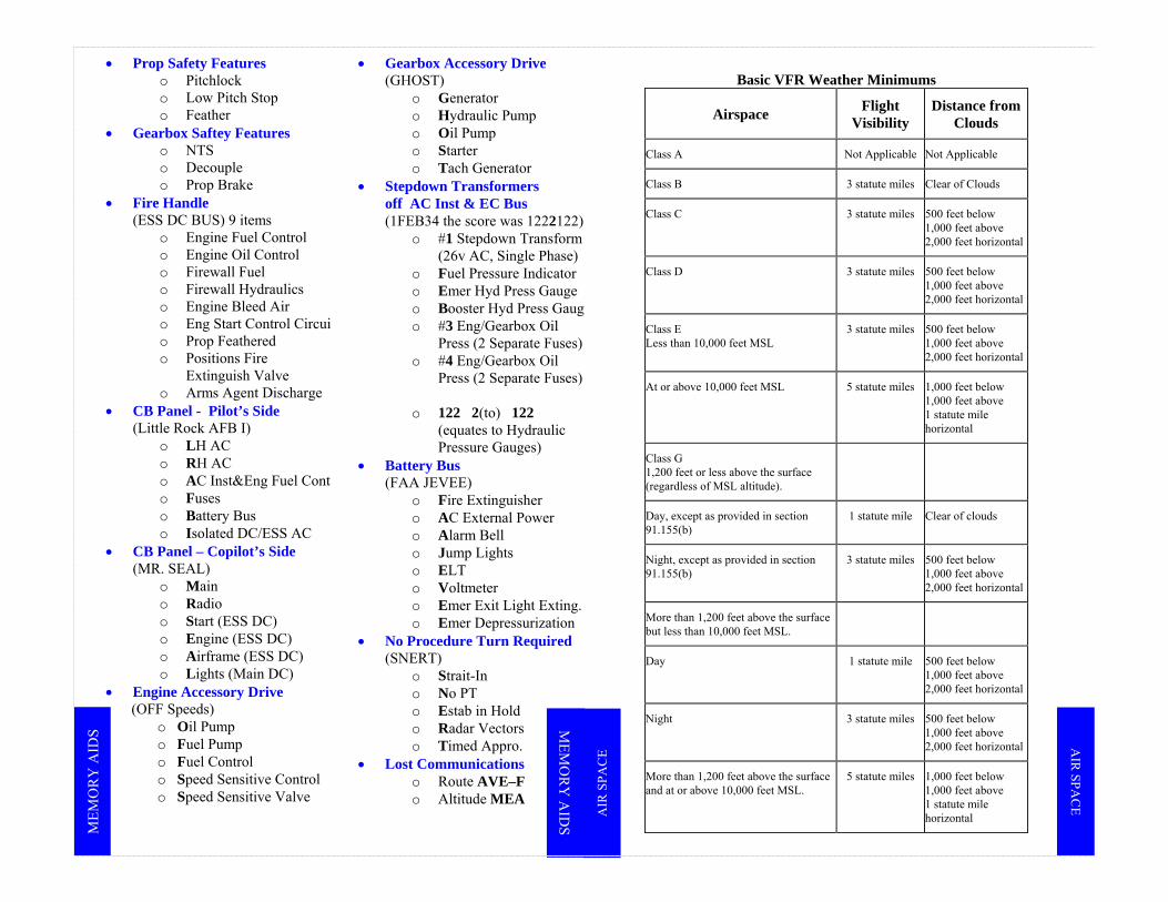
MEM
OR
Y A
IDS
• Prop Safety Features o Pitchlock o Low Pitch Stop o Feather
• Gearbox Saftey Features o NTS o Decouple o Prop Brake
• Fire Handle (ESS DC BUS) 9 items
o Engine Fuel Control o Engine Oil Control o Firewall Fuel o Firewall Hydraulics o Engine Bleed Air o Eng Start Control Circui o Prop Feathered o Positions Fire
Extinguish Valve o Arms Agent Discharge
• CB Panel - Pilot’s Side (Little Rock AFB I)
o LH AC o RH AC o AC Inst&Eng Fuel Cont o Fuses o Battery Bus o Isolated DC/ESS AC
• CB Panel – Copilot’s Side (MR. SEAL)
o Main o Radio o Start (ESS DC) o Engine (ESS DC) o Airframe (ESS DC) o Lights (Main DC)
• Engine Accessory Drive (OFF Speeds)
o Oil Pump o Fuel Pump o Fuel Control o Speed Sensitive Control o Speed Sensitive Valve
• Gearbox Accessory Drive (GHOST)
o Generator o Hydraulic Pump o Oil Pump o Starter o Tach Generator
• Stepdown Transformers off AC Inst & EC Bus (1FEB34 the score was 1222122)
o #1 Stepdown Transform (26v AC, Single Phase)
o Fuel Pressure Indicator o Emer Hyd Press Gauge o Booster Hyd Press Gaug o #3 Eng/Gearbox Oil
Press (2 Separate Fuses) o #4 Eng/Gearbox Oil
Press (2 Separate Fuses)
o 122 2(to) 122 (equates to Hydraulic Pressure Gauges)
• Battery Bus (FAA JEVEE)
o Fire Extinguisher o AC External Power o Alarm Bell o Jump Lights o ELT o Voltmeter o Emer Exit Light Exting. o Emer Depressurization
• No Procedure Turn Required (SNERT)
o Strait-In o No PT o Estab in Hold o Radar Vectors o Timed Appro.
• Lost Communications o Route AVE–F o Altitude MEA
Basic VFR Weather Minimums
Airspace Flight Visibility
Distance from Clouds
Class A Not Applicable Not Applicable
Class B 3 statute miles Clear of Clouds
Class C 3 statute miles 500 feet below 1,000 feet above 2,000 feet horizontal
Class D 3 statute miles 500 feet below 1,000 feet above 2,000 feet horizontal
Class E Less than 10,000 feet MSL
3 statute miles 500 feet below 1,000 feet above 2,000 feet horizontal
At or above 10,000 feet MSL 5 statute miles 1,000 feet below 1,000 feet above 1 statute mile horizontal
Class G 1,200 feet or less above the surface (regardless of MSL altitude).
Day, except as provided in section 91.155(b)
1 statute mile Clear of clouds
Night, except as provided in section 91.155(b)
3 statute miles 500 feet below 1,000 feet above 2,000 feet horizontal
More than 1,200 feet above the surface but less than 10,000 feet MSL.
Day 1 statute mile 500 feet below 1,000 feet above 2,000 feet horizontal
Night 3 statute miles 500 feet below 1,000 feet above 2,000 feet horizontal
More than 1,200 feet above the surface and at or above 10,000 feet MSL.
5 statute miles 1,000 feet below 1,000 feet above 1 statute mile horizontal
MEM
OR
Y A
IDS
AIR
SPA
CE
AIR
SPAC
E

6000’/326°
4000’/333° +12
4000’/013°-10
6000’/026°
150 KTS
180 KTS
210 KTS
All Airspeeds 353°
DOT METHOD - #2 SKE TURN GUIDE 4000’ RANGE RINGS
6000’/333°
4000’/338° +11
4000’/008°-11
6000’/018°
6000’/341°
4000’/343° +8
4000’/003°-8
6000’/011°
4000’: 206000’: 30
4000’: 156000’: 22
4000’: 106000’: 15
RED = ± IAS BLUE = TIME
#1 SKE TU
RN#1
SK
E TU
RN
150 KTS
180 KTS
210 KTS
DOT METHOD - #3 SKE TURN GUIDE 4000’ RANGE RINGS
12000’/300°
8000’/324° -10 8000’/044°
+12
12000’/060°
All Airspeeds 004°
12000’/315°
8000’/334° -11 8000’/034°
+11
12000’/045°
12000’/330°
8000’/344° -8
8000’/024°+8
12000’/030°
8000’: 2012000’: 30
8000’: 3012000’: 45
8000’: 4012000’: 60
RED = ± IAS BLUE = TIME
#2 S
KE
TUR
N #2 SK
E TUR
N

DIV
ERT
BA
SES D
IVER
T BA
SES
150 KTS
180 KTS
210 KTS
DOT METHOD - #4 SKE TURN GUIDE 4000’ (18000’ are 8000’) RANGE RINGS
12000’/300° -0
18000’/280° 18000’/080°
12000’/060°+0
All Airspeeds 360°
12000’/315° -0
18000’/300° 18000’/060°
12000’/045°+0
12000’/330° -0
8000’/315° 18000’/045°
12000’/030°+0
12000’: 3018000’: 45
12000’: 4518000’: 60
12000’: 6018000’: 80
RED = ± IAS BLUE = TIME
#3 SKE TU
RN#3
SK
E TU
RN
McC
ord
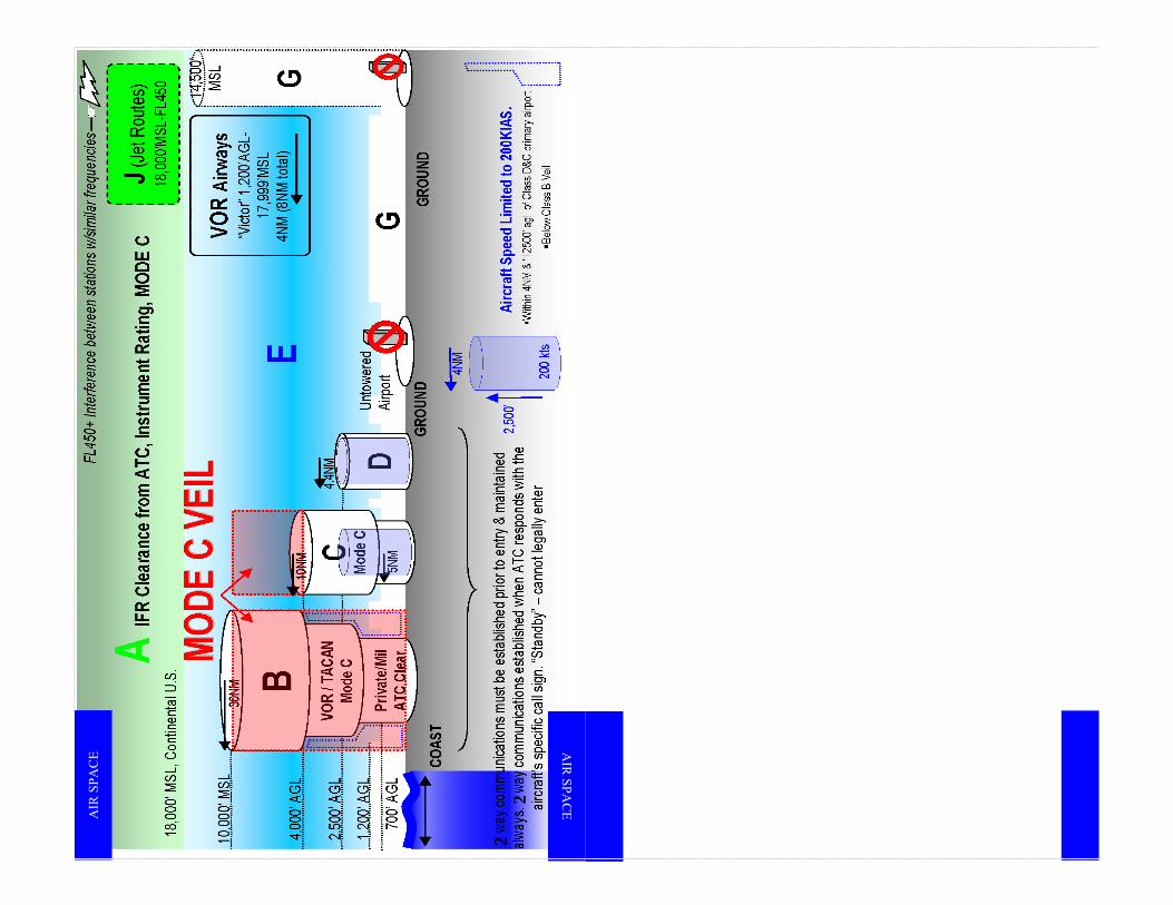
2 2
AIR
SPA
CE A
IR SPA
CE