Bradley Lake Nozzle Refurbish Project lake power... · Bradley Lake Nozzle Refurbish Plan ... •...
23
Bradley Lake Power Project (BLPP) Nozzle Refurbish
-
Upload
vuonghuong -
Category
Documents
-
view
222 -
download
4
Transcript of Bradley Lake Nozzle Refurbish Project lake power... · Bradley Lake Nozzle Refurbish Plan ... •...

Bradley Lake Power Project (BLPP) Nozzle Refurbish

Bradley Lake Unit Overview❖ 2 – FUJI generating units rated at 63 MW each

❖ Vertical shaft with a single turbine/runnerOverview
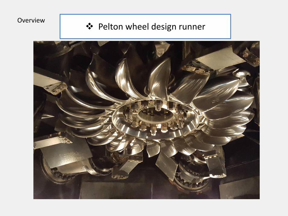
❖ Pelton wheel design runnerOverview

6 nozzles per unit (4 ft. x 6 ft.)Overview

6 nozzles per unit – 3 control modes• Speed mode - all 6 nozzles function as a group
• Power mode - nozzles sequentially operate in pairs 2, 4, or 6 nozzles
• Divider mode – system load rejection events the divider plates enter the water stream to deflect water flow until the nozzle position is reduced, (nozzles have a 90 second stroke time)
Overview
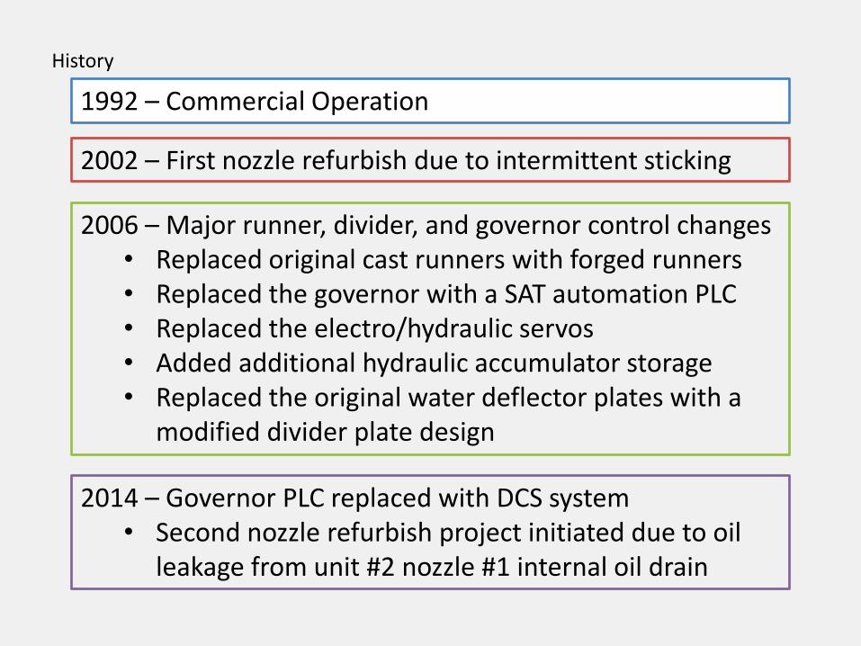
1992 – Commercial Operation
2002 – First nozzle refurbish due to intermittent sticking
2006 – Major runner, divider, and governor control changes• Replaced original cast runners with forged runners• Replaced the governor with a SAT automation PLC• Replaced the electro/hydraulic servos• Added additional hydraulic accumulator storage• Replaced the original water deflector plates with a
modified divider plate design
2014 – Governor PLC replaced with DCS system• Second nozzle refurbish project initiated due to oil
leakage from unit #2 nozzle #1 internal oil drain
History

Bradley Lake Nozzle Refurbish PlanStep 1 – Replace nozzle 2-1 with the spare nozzle
• Tested and proved the functionality of the spare nozzle.
• Utilizing personnel that were involved in the 2002 and 2006 unit modifications, the spare nozzle was installed on unit #2 and the failed nozzle was dismantled to investigate the cause of the failure.
• Catalogued and numbered each O-ring, seal, bushing, and hard metal part.

Step 2 – Re-establish contact with the current FUJI authorized vendor. In the 10 years since the original nozzle refurbish, FUJI had undergone various mergers and changed their distributorship in North America.
Step 1 – Replace nozzle 2-1 with the on site spare nozzle
Refurbish Plan

Step 2 – Re-establish contact with FUJI who had undergone various mergers and changed their distributorship in North America
Step 1 – Replace nozzle 2-1 with the on site spare nozzle
Step 3 – Locate parts and suppliers (4 categories)• Hard parts, (nozzle tips, bushings, piston rings, etc.)• Soft parts, (O-rings, gaskets, u-cup seals)• Machine shop for piston rod refurbishment• Shipping and transportation as Bradley Lake is not
connected to the road system and is landing craft or air freight dependent (approximately 17’ tide to dock a landing craft at Bradley Lake)
Refurbish Plan
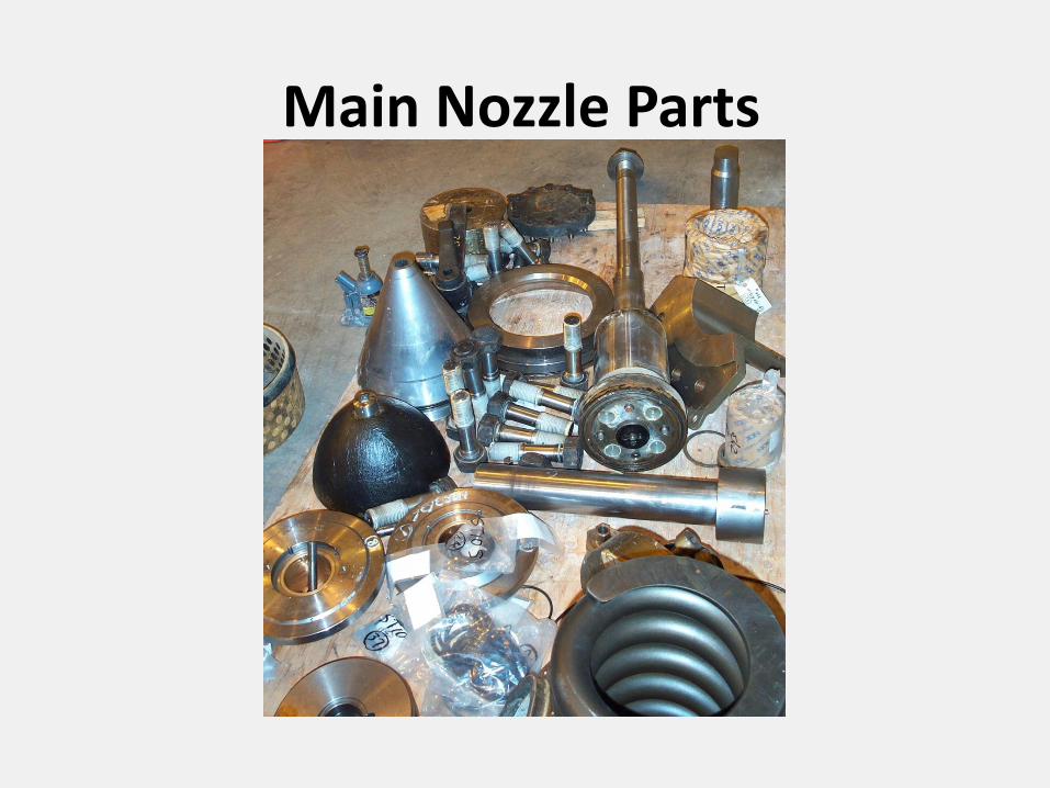
Main Nozzle Parts

Hard wearable parts
Large tip / 32 mm hex Nozzle tip seat ring
Eight bushings – (3” to 18”)
Small nozzle tip
Piston and rings

22 various O-ringsrange from 17 mm to 319 mm
(.6 in to 12 in.)4 large O-ring cords per nozzle
O-rings and seals
U-cup sealsrange from 60 mm to 230 mm
(3” to 9”)

Nozzle wear evaluation

O-Ring wear rolled and/or worn
Oil side O-ring

Piston Rod Wear
Sludge buildup Piston rod corrosion
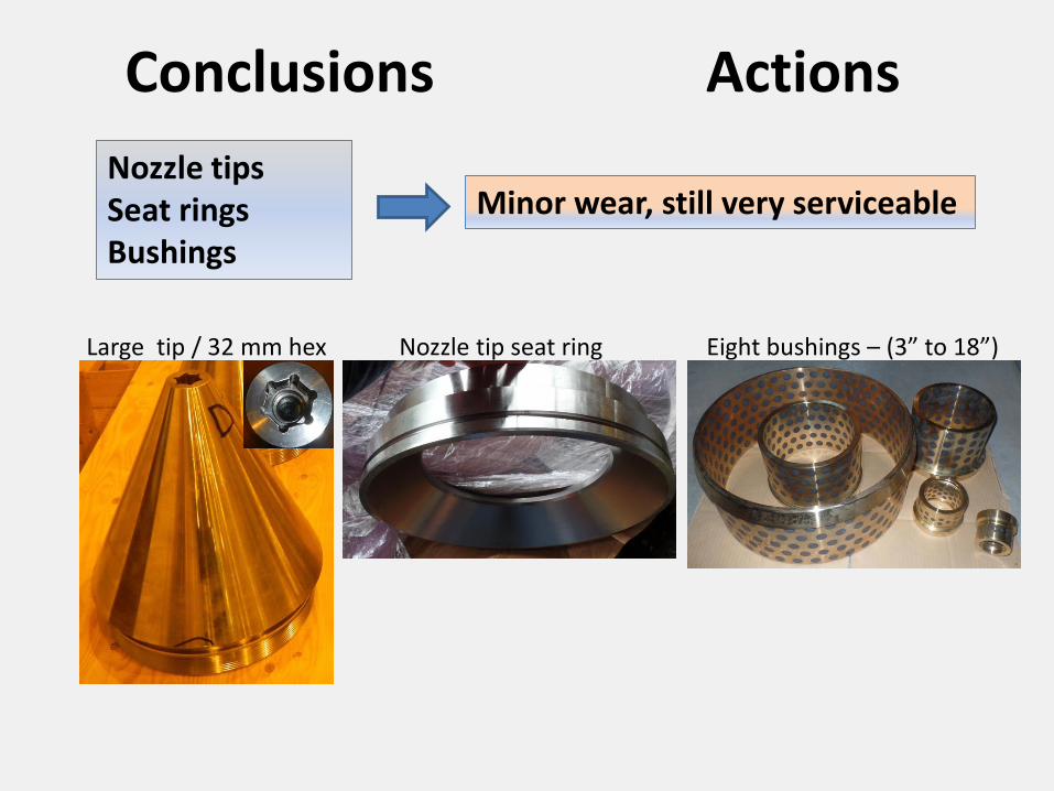
Conclusions Actions
Nozzle tipsSeat ringsBushings
Minor wear, still very serviceable
Large tip / 32 mm hex Nozzle tip seat ring Eight bushings – (3” to 18”)

Conclusions Actions
Nozzle tipsSeat ringsBushings
Minor wear, still very serviceable
Nozzle body Some corrosion and wear in areas where the coal tar coating had failed.
Applied epoxy paint is various test areas.

Piston rodcorrosion
Conclusions Actions
The damaged areas were repaired and sprayed with a High Velocity Oxygen Fuel (HVOF) spray.
The spray material should improve corrosion resistance.
Some of the sprayed areas were polished where needed on sealing surfaces and other areas were left rough where applicable.

Conclusions Actions
O-rings The O-rings were replaced with standard OEM material
Future considerations:• Modern O-ring material
options, resistant to rolling?• Design options such as quad-
ring etc.• Addition of a second O-ring
groove or backer ring
Conclusions Actions
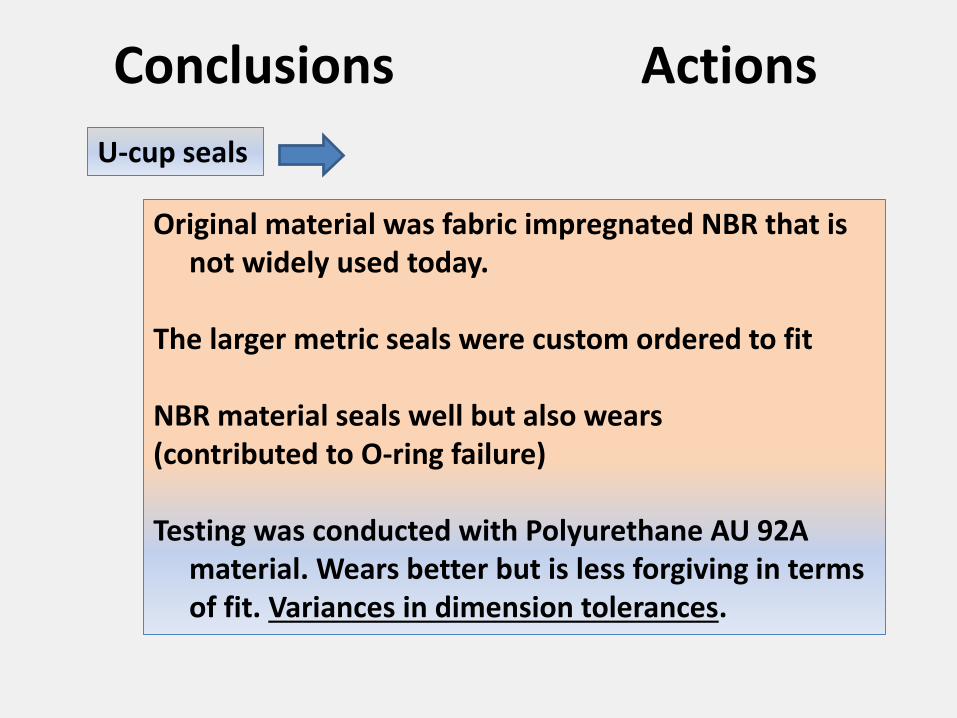
U-cup seals
Original material was fabric impregnated NBR that is not widely used today.
The larger metric seals were custom ordered to fit
NBR material seals well but also wears (contributed to O-ring failure)
Testing was conducted with Polyurethane AU 92A material. Wears better but is less forgiving in terms of fit. Variances in dimension tolerances.

Conclusions Actions
Nozzle design
Future considerations –Are there better more modern designs?
• Refurbish expense vs. complete upgrade?• Ease of serviceability in different design?• Longer wear of seal parts?

Piston Shaft Surface RoughnessPiston Rod Spec Sheet
2015 195mm = 7.6771 in 90 mm = 3.5433
ID# Ø7.6722-7.6738 Ø3.542-3.5428 Ra/Average
A-1 7.6734 3.5426 25-30
A-2 7.6735 3.5425 25-30
A-3 7.6736 3.5427 25-30
A-4 7.6737 3.5422 25-30
A-5 7.6738 3.5426 25-30
A-6 7.6735 3.5426 25-30
B-1 7.6738 3.5424 25-30
2016
ID# Ø7.6722-7.6738 Ø3.542-3.5428 Ra
B-2 7.6737 3.5427 15
B-3 7.6739 3.5425 11
B-4 7.6729 3.5426 13
B-5 7.6727 3.5428 17
B-6 7.6735 3.5423 16
Spare 7.6731 3.5426 16
Surface Roughness Chart