Brad Miller, Ken Streeter, Beth Finn, Jerry Morrison, Dan...
29
C/C++ Getting Started Guide Worcester Polytechnic Institute Robotics Resource Center Brad Miller, Ken Streeter, Beth Finn, Jerry Morrison, Dan Jones, Ryan O’Meara, Derek White, Stephanie Hoag Rev 1.0 Feb 3, 2010
Transcript of Brad Miller, Ken Streeter, Beth Finn, Jerry Morrison, Dan...

C/C++ Getting Started Guide Worcester Polytechnic Institute Robotics Resource Center
Brad Miller, Ken Streeter, Beth Finn, Jerry Morrison, Dan Jones, Ryan O’Meara, Derek White,
Stephanie Hoag
Rev 1.0
Feb 3, 2010

Table of Contents
Changes from Version 4.0 to 4.1 ......................................................................................... 3
What is the WPI Robotics Library ..................................................................................... 4
Using Wind River Workbench and C/C++ ....................................................................... 5
Setting up the environment .......................................................................................................................................................................5
Creating a Remote System in Workbench ..........................................................................................................................................5
Creating a robot project ....................................................................................................... 8
Building your project .......................................................................................................... 10
Downloading the project to the cRIO .............................................................................. 11
Debugging your robot program ........................................................................................ 12
Troubleshooting ....................................................................................................................................................................................... 15
Getting printf/cout output on the PC .................................................................................................................................................. 15
Deploying the C/C++ Program ......................................................................................... 16
Creating a Robot Program ................................................................................................ 17
Using objects ........................................................................................................................ 20
Creating object instances ........................................................................................................................................................................ 20
Pointers and addresses ............................................................................................................................................................................. 21
WPI Robotics Library Conventions.................................................................................................................................................... 21
Class, method, and variable naming ................................................................................................................................................... 21
Constructors with slots and channels ................................................................................................................................................. 22
SimpleRobot class ..................................................................................................................................................................................... 24
IterativeRobot class ................................................................................................................................................................................... 24
RobotBase class .......................................................................................................................................................................................... 25
C++ Tips ............................................................................................................................... 28
Contributing to the WPI Robotics Library .................................................................... 29

Changes from Version 4.0 to 4.1 There have been several changes from Version 4.0 to 4.1. Most are source-code compatible meaning that you won’t have to change any of the code that you have written. One change may require you to make changes to your source code.
Improved camera support. The AxisCamera class now is much more robust and should be much more resilient to different ordering of powering on the cRIO and the camera. Also it will be less likely to cause problems in the case of a intermittent power failure.
The camera code now is much more efficient with less copies and image buffer allocations in the library.
The PC Video server (images back to the dashboard) are much faster now – it should in most cases run at the full camera rate. For image sizes of 320x240 the total lag should be around 0.5 seconds. Smaller images are lower.
The kit I2C accelerometer is now supported in the ADXL345 class.
Note: the Axis Camera and Image classes have been renamed to have upper case first character names with camel case for the rest of the name. The names are the same as before, but now everything is consistently using the same naming convention. This will be a one-time change and should be pretty easy to implement in any code using the vision classes.
Many I2C cleanups in the code.
The default gyro sensitivity now matches the 2010 kit gyro. You can still explicitly set the sensitivity in V/deg/sec using the Gyro.SetSensitivity method on the gyro class.
Several other bug fixes and improvements throughout the library.
What is the WPI Robotics Library The WPI Robotics library is a set of classes that interface to the hardware in the FRC control system and your robot. There are classes to handle sensors, motors, the driver station, and a number of other utility functions like timing and field management.
We believe that the object oriented programming paradigm best fits robot programming with WPILib, but C programming is available for those with C experience. Here is an example of using C with the WPI Robotics Library.
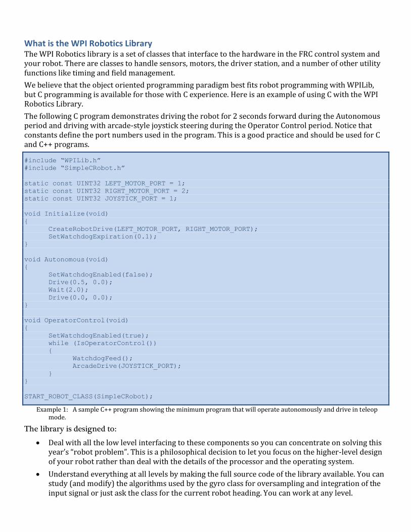
The following C program demonstrates driving the robot for 2 seconds forward during the Autonomous period and driving with arcade-style joystick steering during the Operator Control period. Notice that constants define the port numbers used in the program. This is a good practice and should be used for C and C++ programs.
#include “WPILib.h”
#include “SimpleCRobot.h”
static const UINT32 LEFT_MOTOR_PORT = 1;
static const UINT32 RIGHT_MOTOR_PORT = 2;
static const UINT32 JOYSTICK_PORT = 1;
void Initialize(void)
{
CreateRobotDrive(LEFT_MOTOR_PORT, RIGHT_MOTOR_PORT);
SetWatchdogExpiration(0.1);
}
void Autonomous(void)
{
SetWatchdogEnabled(false);
Drive(0.5, 0.0);
Wait(2.0);
Drive(0.0, 0.0);
}
void OperatorControl(void)
{
SetWatchdogEnabled(true);
while (IsOperatorControl())
{
WatchdogFeed();
ArcadeDrive(JOYSTICK_PORT);
}
}
START_ROBOT_CLASS(SimpleCRobot);
Example 1: A sample C++ program showing the minimum program that will operate autonomously and drive in teleop mode.
The library is designed to:
Deal with all the low level interfacing to these components so you can concentrate on solving this year’s “robot problem”. This is a philosophical decision to let you focus on the higher-level design of your robot rather than deal with the details of the processor and the operating system.
Understand everything at all levels by making the full source code of the library available. You can study (and modify) the algorithms used by the gyro class for oversampling and integration of the input signal or just ask the class for the current robot heading. You can work at any level.

Using Wind River Workbench and C/C++ The develop tools to create C++ robot programs is called Workbench from Wind River. Wind River Workbench is a complete C/C++ Interactive Development Environment (IDE) that handles all aspects of code development. It will help you:
Write the code for your robot with editors, syntax highlighting, formatting, auto-completion, etc.
Compile the source code into binary object code for the cRIO PowerPC architecture.
Debug and test code by downloading the code to the cRIO robot controller and enabling you to step through line by line and examine variables of the running code.
Deploy the program so that it will automatically start up when the robot is powered on.
You can even use Subversion, a popular source code repository server to manage your code and track changes. This is especially useful if there is more than one person doing software development.
Setting up the environment To use Workbench you need to configure it so that it knows about your robot and the programs that you want to download to it. There are three areas that need to be set up.
1. The target remote system, which is the cRIO that you will use to download and debug your programs.
2. The run or debug configuration that describes the program to be debugged and which remote system you want to debug it on.
3. The FIRST Downloader settings that tell which program should be deployed onto the cRIO when you are ready to load it for a competition or operation without the laptop.
Creating a Remote System in Workbench Workbench connects to your cRIO controller and can download and remotely debug programs running on it. In order to make that connection, Workbench needs to add your cRIO to its list of Remote Systems. Each entry in the list tells Workbench the network address of your cRIO and the location of a kernel file that is required for remote access. To create the entry for your system perform the following steps.
Note: The “Reset connected Target” (reboot the server) command doesn’t work reliably and other features
seem to have issues unless the “Console out” switch on the cRIO is set to on. Normally this switch
enables the console output for viewing with a serial port, but leaving it on even if there is no serial
cable connected improves system reliability.
Right-click in the empty area in the “Remote Systems” window and select “New Connection”.

In the “Select Remote System Type” window choose “Wind River VxWorks 6.x Target Server Connection” and
click “Next”.
Fill out the “Target Server Options” window with the IP address of your cRIO. It is usually 10.x.y.2 where x is
the first 2 digits of your 4 digit team number and y is the last two digits. For example, team 190 (0190) would be
10.1.90.2. You must also select a Kernel Image file. This is located in the WindRiver install directory in the
WPILib top level directory called “C:\WindRiver\WPILib\VxWorks”.

If the cRIO is turned on and connected you will see the target server entry populated with the tasks currently
running.
Creating a robot project The easiest way to create your own project for your robot is to start with one of the existing templates:
SimpleRobotTemplate
IterativeRobotTemplate
In both cases the templates are based on the RobotBase class and have some of the functions overridden to change the behavior. Additional templates can be implemented that implement other behaviors for example event driven models.
Follow these steps to create a sample project. In this case the sample is the SimpleRobotTemplate, but you can use any of the provided samples.
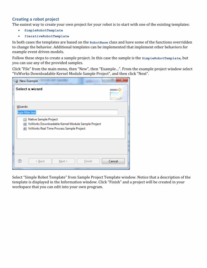
Click “File” from the main menu, then “New”, then “Example…”. From the example project window select “VxWorks Downloadable Kernel Module Sample Project”, and then click “Next”.
Select “Simple Robot Template” from Sample Project Template window. Notice that a description of the template is displayed in the Information window. Click “Finish” and a project will be created in your workspace that you can edit into your own program.


Building your project The project is built by right-clicking on the project name in the Project Explorer window and selecting “Build project” or “Rebuild project” from the popup context menu. This will cause Workbench to compile and link the project files into a .OUT executable file that may be either deployed or downloaded to the cRIO.
Note: Sometimes in Workbench when a new project is created building it the first time doesn’t actually build
anything. You won’t notice very much activity in the “Build Console” tab. If this happens, simply exit
and restart Workbench and rebuild. This seems to only happen the first time a project is built after
being created.
Another way of building the project is to automatic rebuild feature of Workbench. Whenever a file in the project is saved, a build will automatically be started to keep the project up to date. To enable this feature:
1. Select “Window”, then “Preferences”. 2. In the Preferences panel, expand “General”, then “Workspace” and check the “Build automatically”
option. A file can quickly be saved after editing by using the keyboard shortcut, Ctrl-S. Or save all open files at once using the Save All shortcut, Ctrl-Shift-S.
It’s handy to turn on “Save automatically before build.” Then Workbench will always build with your latest changes to all files.

Downloading the project to the cRIO There are two ways of getting your project into the cRIO:
Using a Run/Debug Configuration in Workbench. This loads the program into the cRIO RAM memory and allows it to run either with or without the debugger. When the robot is rebooted, the program will no longer be in memory.
Deploy the program through the FIRST Downloader option in Workbench. In this case the program will be written to the flash disk inside the cRIO and will run whenever it is rebooted or until it is Undeployed (deleted from flash). This is the option to use for a finished program and make it available for a match – so that it will run without an attached computer to always load it.
Note: Be sure to not use the Run/Debug configuration if you have a robot program deployed and thus
starting up automatically in the background. Use the Undeploy menu item if you think there is already
one there otherwise having two programs trying to run at the same time will be very confusing.
It is also sometimes advantageous to reboot between debugging sessions. Sometimes things don’t get completely cleaned up even if you try to unload the program. We’re working on that. You can reboot remotely by right clicking on the connection in the “Remote Systems” tab in Workbench and selecting “Reset connected Target”. It takes about 15 seconds to reboot. You can also reboot the cRIO via the Reboot option on the Driver Station.

Debugging your robot program You can monitor, control and manipulate processes using the debugger. This section will describe how to set up a debug session on a robot control program for the cRIO. (See the Wind River Workbench User’s Guide for complete documentation on how to use the debugger: Help > Help Contents > Wind River Documentation > Guides > Host Tools > Wind River Workbench User’s Guide.)
To run a program that derives from one of the WPILib robot base classes, such as SimpleRobot.cpp or IterativeRobot.cpp, a macro called START_ROBOT_CLASS is used that starts one task that just spawns the robot task with the correct run options. See SimpleDemo or IterativeDemo for examples. This makes it necessary to set up the debug options to attach to the spawned robot task instead of just the initial task.
To start a debug session first make sure that the PC is connected to the target. Right-click on the project name in the “Project Explorer” window and select “Debug Kernel Task…” The Debug dialog is displayed.
Figure 1: Setting the entry point on a Debug Configuration for a robot program.
Change the name of the debug target to something meaningful like “2010TargetTest” shown in the example. Select as the entry point the function FRC_UserProgram_StartupLibraryInit. On the debug options tab, select “Break on Entry” and “Automatically attach spawned Kernel Tasks”. This tells the debugger to stop at the first instruction, and to make the spawned task (your robot task) available to debug.

Figure 2: Setting the “Automatically attach spawned Kernel Tasks” option ensures that you will be able to debug the entire program
including any tasks that it creates. The WPI Robotics Library automatically starts your program in a new task.
The other options can normally be left at default settings. Apply your changes.
When the “Debug” button is selected, several things happen. Your Workbench display changes to the Debug Perspective, which has the views Debug, Breakpoints and Variables along the right side of the window. The task is started and stops at the first program statement, in FRC_UserProgram_StartupLibraryInit. At this point double-click in the left margin of the source code window to set a breakpoint in your user program.
A small blue circle indicates the breakpoint has been set on the corresponding line. Select the “Resume” icon (the green arrow) to continue until the first breakpoint is reached.

The program will stop at the line where you set the breakpoint at the source line will be highlited.
The Debug view shows all processes and threads running in the cRIO. Selecting the stack frame will show the current instruction pointer and source code (if available) for the process selected. When your breakpoint is reached, make sure your program is selected in the task list, and your source code is displayed with a program pointer. You can continue through your code using “Resume”, “Step Into”, “Step Over” and “Step Return”.
If you see assembly code displayed this is because you have gone into a lower level of code where the source is not available. A “Step Return” will bring you back up a level.
The lower right view shows the current value of variables. To see a variable that is not displayed, select the
“Expressions” tab and enter the variable name. If it is in scope, its current value will be shown.

To stop debugging, you may disconnect or terminate the process. Disconnecting detaches the debugger but leaves the process running in its current state. Terminating the process kills it on the target.
Troubleshooting:
Source code displayed is out of sync with cursor when debugging: The source has changed since it was loaded onto the cRIO. Rebuild the project (build clean) and make sure included projects are up to date.
Robot program not visible in the Debug View: Make sure that “Automatically attach spawned Kernel Tasks” option is set. The first stop happens before your program is started. It will appear after you “Resume.”
Getting printf/cout output on the PC There are four ways to see output from printf/cout in Workbench, all with advantages and disadvantages
Method of communication Advantages Disadvantages
Connect a serial cable between the computer and
robot controller
Always works over
system reboots
Robot must be tethered
Use a network Target Console. To get that, right-
click on the remote system, then “Target Tools”,
then “Target Console”. This will create a console
window over the network.
Gets everything with
no tether cable
Goes away on reboot
Allocate a console. In the Run menu, select Open
Run Dialog… or Open Debug Dialog… to open the
run or debug configuration. Select your Kernel
Task FRC_UserProgram_StartupLibraryInit in the
left pane. Then look at the “Common” tab. There
check the “Allocate Console” checkbox.
Survives reboots Prints current task output
NetConsole over Ethernet Captures all stdout,
stderr, and VxWorks
commands
Requires NetConsole task
to be running on the cRIO
Deploying the C/C++ Program Deploying a program to the cRIO copies it to flash memory so that it will automatically start when the robot is turned on. The FIRST Downloader plug-in for Workbench has commands to download (i.e. deploy) the program to the cRIO and Undeploy (i.e. delete) the program from the cRIO.
Note: Don’t try to debug a robot program as described above while there is a deployed robot program that
automatically runs when the cRIO boots.
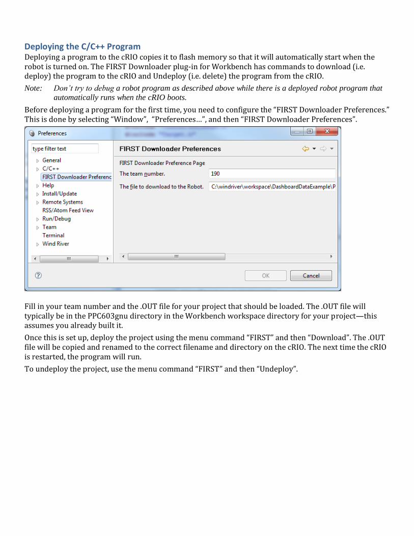
Before deploying a program for the first time, you need to configure the “FIRST Downloader Preferences.” This is done by selecting “Window”, “Preferences…”, and then “FIRST Downloader Preferences”.
Fill in your team number and the .OUT file for your project that should be loaded. The .OUT file will typically be in the PPC603gnu directory in the Workbench workspace directory for your project—this assumes you already built it.
Once this is set up, deploy the project using the menu command “FIRST” and then “Download”. The .OUT file will be copied and renamed to the correct filename and directory on the cRIO. The next time the cRIO is restarted, the program will run.
To undeploy the project, use the menu command “FIRST” and then “Undeploy”.

Creating a Robot Program Now consider a very simple robot program that has these characteristics:
Autonomous
period
Drives in a square pattern by driving half speed for 2
seconds to make a side then turns 90 degrees. This is
repeated 4 times.
Operator Control
period
Uses two joysticks to provide tank steering for the robot.
The robot specifications are:
Left drive motor PWM port 1
Right drive motor PWM port 2
Joystick Driver station joystick port 1
Starting with the simple template for a robot program we have:
#include “WPILib.h”
class RobotDemo : public SimpleRobot
{
public:
RobotDemo()
{
// put initialization code here
}
void Autonomous()
{
// put autonomous code here
}
void OperatorControl()
{
// put operator control code here
}
};
START_ROBOT_CLASS(RobotDemo);
Example 2: Starting point for robot program
Now add objects to represent the motors and joystick. The robot drive object with motors in ports 1 and 2, and two joystick objects are declared using the following code:
RobotDrive drive(1, 2);
Joystick leftStick(1);
Joystick rightStick(2);
Example 3: C++ Example 2: Adding joystick and robot drive objects to the program
For the example and to make the program easier to understand, we’ll disable the watchdog timer. This is a feature in the WPI Robotics Library that helps ensure that your robot doesn’t run off out of control if the program malfunctions.

RobotDemo()
{
GetWatchdog().SetEnabled(false);
}
Example 4: Disabling the watchdog timer
Now the autonomous part of the program can be constructed that drives in a square pattern:
void Autonomous()
{
for (int i = 0; i < 4; i++)
{
drivetrain.Drive(0.5, 0.0); // drive 50% of full forward with 0% turn
Wait(2.0); // wait 2 seconds
drivetrain.Drive(0.0, 0.75); // drive 0% forward and 75% turn
}
Drivetrain.Drive(0.0, 0.0); // drive 0% forward, 0% turn (stop)
}
Example 5: Autonomous program that drives in a square pattern
Now look at the operator control part of the program:
void OperatorControl()
{
while (1) // loop forever
{
drivetrain.TankDrive(leftStick, rightStick);// drive with the joysticks
Wait(0.005);
}
}
Example 6: Simple tank drive with two joysticks
Putting it all together we get this very short program that accomplishes some autonomous task and provides operator control tank steering:

#include “WPILib.h”
class RobotDemo : public SimpleRobot
{
RobotDrive drivetrain(1, 2);
Joystick leftStick(1);
Joystick rightStick(2);
public:
RobotDemo()
{
GetWatchdog().SetEnabled(false);
}
void Autonomous()
{
for (int i = 0; i < 4; i++)
{
drivetrain.Drive(0.5, 0.0); // drive 50% forward, 0% turn
Wait(2.0); // wait 2 seconds
drivetrain.Drive(0.0, 0.75); // drive 0% forward and 75% turn
Wait(0.75); // turn for almost a second
}
drivetrain.Drive(0.0, 0.0); // stop the robot
}
void OperatorControl()
{
while (1) // loop forever
{
drivetrain.Tank(leftStick, rightStick); // drive with the joystick
Wait(0.005);
}
}
};
Example 7: Completed example program
Although this program will work perfectly with the robot as described, there were some details that were skipped:
In the example drivetrain,leftStick and rightStick are member objects of the RobotDemo class. They were accessed using references, one of the ways of accessing object members. In the next section pointers will be introduced as an alternate technique.
The drivetrain.Drive() method takes two parameters, a speed and a turn direction. See the documentation about the RobotDrive object for details on how that speed and direction really work.
The Watchdog timer was disabled – in general a bad idea! You should enable the watchdog timer, set the feeding interval, and be sure to “Feed” it at least that often.

Using objects In the WPI Robotics Library all sensors, motors, driver station elements, and more are all objects. For the most part, objects correspond to the physical things on your robot. Objects include the code and the data that makes the thing operate. Let’s look at a Gyro. There are a number of operations, or methods, you can perform on a gyro:
Create the gyro object – this sets up the gyro and causes it to initialize itself
Get the current heading, or angle, from the gyro
Set the type of the gyro, i.e. its Sensitivity
Reset the current heading to zero
Delete the gyro object when you’re done using it
Creating a gyro object is done like this:
Gyro robotHeadingGyro(1);
robotHeadingGyro is a variable that holds the Gyro object that represents a gyro module connected to analog port 1.
That’s all you have to do to make an instance of a Gyro object.
Note: An instance of an object is the chunk of memory that holds the data unique to that object. When you
create an object that memory is allocated and when you delete the object that memory is deallocated.
To get the current heading from the gyro, you simply call the GetAngle method on the gyro object. Calling the method is really just calling a function that works on the data specific to that gyro instance.
float heading = robotHeadingGyro.GetAngle();
This sets the variable heading to the current heading of the gyro connected to analog channel 1.
Creating object instances There are several ways of creating object instances used throughout the WPI Robotics Library and all the examples. Depending on how the object is created there are differences in how the object is referenced and deleted. Here are the rules:

Location Creating object Using the object When the object is deleted
Local variable
declared inside a block
or function (or inside
another object)
Victor leftMotor(3); leftMotor.Set(1.0); Object is implicitly deallocated
when the enclosing block is exited
Global declared
outside of any
enclosing blocks or
functions; or a static
variable
Victor leftMotor(3); leftMotor.Set(1.0); Object is not deallocated until the
program exits
Pointer to object
Victor *leftMotor =
new Victor(3);
leftMotor-
>Set(1.0);
Object must be explicitly
deallocated using the C++ delete
operator.
How do you decide what to use? The next section will discuss this.
Pointers and addresses There are two ways of declaring objects: either as an instance of the object or a pointer to the object. In the case of the instance the variable represents the object, and it is created at the time of the declaration. In the case of a pointer you are only creating the space to store the address of the object, but the object remains uncreated. With pointers you have to create the object using the new operator. Look at these two snippets of code to see the difference.
Joystick stick1(1); // this is an instance of a Joystick object stick1
stick1.GetX(); // instance dereferenced using the dot (.) operator
bot->ArcadeDrive(stick1); // and can be passed to methods as a reference
Joystick *stick2; // a pointer to an uncreated Joystick object
stick2 = new Joystick(1); // creates the instance of the Joystick object
stick2->GetX(); // pointers are dereferenced with the arrow (->)
bot->ArcadeDrive(stick2); // and can be passed as pointers (notice, no &)
delete stick2; // delete the object when you’re done with it
The ArcadeDrive method in the library is taking advantage of a feature of C++ called function overloading. This allows us to have two methods with the same name that differ by the argument list. In the first ArcadeDrive(stick1), the variable stick1 is passed as a reference to a Joystick object. In the second ArcadeDrive(stick2), it is being passed as a pointer to a Joystick object. There are actually two methods in the RobotDrive object, both called ArcadeDrive that each take a different type of argument. The cool thing is that the compiler figures out which one to call. The library is built this way to let it adapt to the style of programmers that prefer to use pointers while at the same time accommodating those who prefer to use references.
WPI Robotics Library Conventions This section documents some conventions that were used throughout the library to standardize on its use and make things more understandable. Knowing these should make your programming job much easier.
Class, method, and variable naming Names of things follow the following conventions:
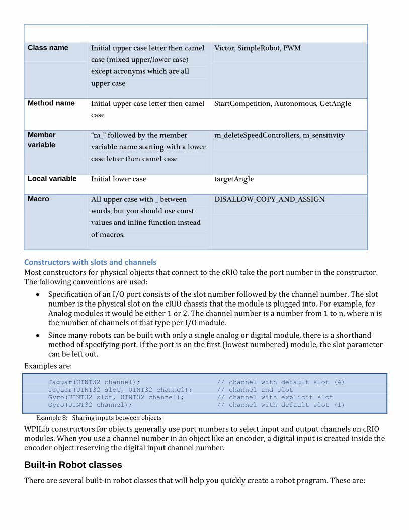
Type of name Naming rules Examples
Class name Initial upper case letter then camel
case (mixed upper/lower case)
except acronyms which are all
upper case
Victor, SimpleRobot, PWM
Method name Initial upper case letter then camel
case
StartCompetition, Autonomous, GetAngle
Member
variable
“m_” followed by the member
variable name starting with a lower
case letter then camel case
m_deleteSpeedControllers, m_sensitivity
Local variable Initial lower case targetAngle
Macro All upper case with _ between
words, but you should use const
values and inline function instead
of macros.
DISALLOW_COPY_AND_ASSIGN
Constructors with slots and channels Most constructors for physical objects that connect to the cRIO take the port number in the constructor. The following conventions are used:
Specification of an I/O port consists of the slot number followed by the channel number. The slot number is the physical slot on the cRIO chassis that the module is plugged into. For example, for Analog modules it would be either 1 or 2. The channel number is a number from 1 to n, where n is the number of channels of that type per I/O module.
Since many robots can be built with only a single analog or digital module, there is a shorthand method of specifying port. If the port is on the first (lowest numbered) module, the slot parameter can be left out.
Examples are:
Jaguar(UINT32 channel); // channel with default slot (4)
Jaguar(UINT32 slot, UINT32 channel); // channel and slot
Gyro(UINT32 slot, UINT32 channel); // channel with explicit slot
Gyro(UINT32 channel); // channel with default slot (1)
Example 8: Sharing inputs between objects
WPILib constructors for objects generally use port numbers to select input and output channels on cRIO modules. When you use a channel number in an object like an encoder, a digital input is created inside the encoder object reserving the digital input channel number.
Built-in Robot classes
There are several built-in robot classes that will help you quickly create a robot program. These are:

Table 1: Built-in robot base classes to create your own robot program. Subclass one of these depending on your requirements and preferences.
Class name Description
SimpleRobot This template is the easiest to use and is designed for writing a straight-line autonomous
routine without complex state machines.
Pros:
Only three places to put your code: the constructor for initialization, the Autonomous method for autonomous code and the OperatorControl method for teleop code.
Sequential robot programs are trivial to write, just code each step one after another.
No state machines required for multi-step operations, the program can simply do each step sequentially.
Cons:
Automatic switching between Autonomous and Teleop code segments is not easy and may require rebooting the controller.
The Autonomous method will not quit running until it exits, so it will continue to run through the TeleOp period unless it finishes by the end of the Autonomous period (so be sure to make your loops check that it’s still the autonomous period).
IterativeRobot This template gives additional flexibility in the code for responding to various field state changes (autononmous, teleoperated, disabled) in exchange for additional complexity in the program design. It is based on a set of methods that are repeatedly called based on the current state of the field. The intent is that each method is called; it does some processing, and then returns. That way, when the field state changes, a different method can be called as soon as the change happens.
Pros:
Can have very fine-grain control of field state changes, especially if practicing and retesting the same state over and over.
Cons:
More difficult to write action sequences that unfold over time. It requires state variables to remember what the robot is doing from one call the next.
RobotBase The base class for the above classes. This provides all the basic functions for field control, the user watchdog timer, and robot status. This class should be extended to have the required specific behavior.

SimpleRobot class The SimpleRobot class is designed to be the base class for a robot program with straightforward transitions from
Autonomous to Operator Control periods. There are three methods that are usually filled in to complete a SimpleRobot
program.
Table 2: SimpleRobot class methods that are called as the match moves through each phase.
Method What it does
the Constructor
(method with the
same name as the
robot class)
Put all the code in the constructor to initialize sensors and any program variables that you have. This code runs as soon as the robot is turned on, but before it is enabled. When the constructor exits, the program waits until the robot is enabled.
Autonomous() All the code that should run during the autonomous period of the game goes in the Autonomous method. The method is allowed to run to completion and will not be interrupted at the end of the autonomous period. If the method has an infinite loop, it will never stop running until the entire match ends. When the method exits, the program will wait until the start of the operator control period.
OperatorControl() Put code in the OperatorControl method that should run during the operator control part of the match. This method will be called after the Autonomous() method has exited and the field has switched to the operator control part of the match. If your program exits from the OperatorControl() method, it will not resume until the robot is reset.
IterativeRobot class The IterativeRobot class divides your program up into methods that are repeatedly called at various times as the robot
program executes. For example, the AutonomousContinuous() method is called continually during the autonomous
period. When the playing field (or the switch on the DS) changes to operator control, then the TeleopInit() first, then the
TeleopContinuous() methods are called continuously.
WindRiver Workbench has a built in sample robot program based on the Iterative Robot base class. If you would like to
use it, follow the instructions from the previous section, except select “Iterative Robot Main Program”. The project will be
created in your workspace.
The methods that the user fills in when creating a robot based on the IterativeRobot base class are:
Table 3: IterativeRobot class methods that are called as the match proceeds through each phase.
Method name Description
RobotInit Called when the robot is first turned on. This is a substitute for using the constructor in
the class for consistency. This method is only called once.
DisabledInit Called when the robot is first disabled

AutonomousInit Called when the robot enters the autonomous period for the first time. This is called on a
transition from any other state.
TeleopInit Called when the robot enters the teleop period for the first time. This is called on a
transition from any other state.
DisabledPeriodic Called periodically during the disabled time based on a periodic timer for the class.
AutonomousPeriodic Called periodically during the autonomous part of the match based on a periodic timer
for the class.
TeleopPeriodic Called periodically during the teleoperation part of the match based on a periodic timer for the class.
DisabledContinuous Called continuously while the robot is disabled. Each time the program returns from this function, it is immediately called again provided that the state hasn’t changed.
AutonomousContinuous Called continuously while the in the autonomous part of the match. Each time the program returns from this function, it is immediately called again provided that the state hasn’t changed.
TeleopContinuous Called continuously while in the teleop part of the match. Each time the program returns from this function, it is immediately called again provided that the state hasn’t changed.
The three Init methods are called only once each time state is entered. The Continuous methods are called repeatedly while in that state, after calling the appropriate Init method. The Periodic methods are called periodically while in a given state where the period can be set using the SetPeriod method in the IterativeRobot class. The periodic methods are intended for timebased algorithms like PID control. Any of the provided methods will be called at the appropriate time so if there is a TeleopPeriodic and TeleopContinous, they will both be called (although at different rates).
RobotBase class The RobotBase class is the subclass for the SimpleRobot and IterativeRobot classes. It is intended that if you decide to create your own type or robot class it will be based on RobotBase. RobotBase has all the methods to determine the field state, set up the watchdog timer, communications, and other housekeeping functions.
To create your own base class, create a subclass of RobotBase and implement (at least) the StartCompetition() method.
For example, the SimpleRobot class definition looks (approximately) like this:

class SimpleRobot: public RobotBase
{
public:
SimpleRobot();
virtual void Autonomous();
virtual void OperatorControl();
virtual void RobotMain();
virtual void StartCompetition();
private:
bool m_robotMainOverridden;
};
It overrides the StartCompetition() method that controls the running of the other methods and it adds the Autonomous(), OperatorControl(), and RobotMain() methods. The StartCompetition method looks (approximately) like this:
void SimpleRobot::StartCompetition()
{
while (IsDisabled()) Wait(0.01); // wait for match to start
if (IsAutonomous()) // if starts in autonomous
{
Autonomous(); // run user-supplied Autonomous code
}
while (IsAutonomous()) Wait(0.01); // wait until end of autonomous period
while (IsDisabled()) Wait(0.01); // make sure robot is enabled
OperatorControl(); // start user-supplied OperatorControl
}
It uses the IsDisabled() and IsAutonomous() methods in RobotBase to determine the field state and calls the correct methods as the match is sequenced.
Similarly the IterativeRobot class calls a different set of methods as the match progresses.
Watchdog timer class
The Watchdog timer class helps to ensure that the robot will stop operating if the program does something unexpected or crashes. A watchdog object is created inside the RobotBase class (the base class for all the robot program templates). Once created, the robot program is responsible for “feeding” the watchdog periodically by calling the Feed() method on the Watchdog. Failure to feed the Watchdog results in all the motors and pneumatics stopping on the robot.
The default expiration time for the Watchdog is 500ms (0.5 second). Programs can override the default expiration time by calling the SetExpiration(expiration-time-in-seconds) method on the Watchdog.
Use of the Watchdog timer is recommended for safety, but it can be disabled. For example, during the autonomous period
of a match the robot needs to drive for drive for 2 seconds then make a turn. The easiest way to do this is to start the robot
driving, and then use the Wait function for 2 seconds. During the 2-second period when the robot is in the Wait function,
there is no opportunity to feed the Watchdog. In this case you could disable the Watchdog at the start of the
Autonomous() method and re-enable it at the end. Alternatively a longer watchdog timeout period would still
provide much of the protection from the watchdog timer.

void Autonomous()
{
GetWatchdog().SetEnabled(false); // disable the watchdog timer
Drivetrain.Drive(0.75, 0.0); // drive straight at 75% power
Wait(2.0); // wait for 2 seconds
.
.
.
GetWatchdog().SetEnabled(true); // reenable the watchdog timer
}
You can call GetWatchdog() from any of the methods inside one of the robot program template objects.

C++ Tips

Contributing to the WPI Robotics Library We are accepting requests from teams or groups of team members who would like to create Community projects to share with other FRC teams. Those projects can be hosted on our SourceForge server located at http://firstforge.wpi.edu. These community projects will have a administrator member and contributors to the project. All the project code will be readable by the entire first community, but only the designated project members can make changes.