Braas Company Denso Training. Denso Training - Agenda Hardware Overview Jogging the robot Teaching...
99
Braas Company Denso Training
-
Upload
nayeli-green -
Category
Documents
-
view
217 -
download
1
Transcript of Braas Company Denso Training. Denso Training - Agenda Hardware Overview Jogging the robot Teaching...

Braas Company
Denso Training

Denso Training - Agenda
• Hardware Overview• Jogging the robot• Teaching Positions (using the Teach Pendant)• Configuring the Robot• Programming (Using the Teach Pendant)• I/O Interfacing (Hardware)• Overview of Development Software• Maintenance

Denso – Hardware Overview -Controller

Denso – Hardware Overview -Joints

Denso – Hardware Overview -Joints

Denso – Hardware Overview – Connections - VSGThe VS-G Series is equipped with 2 air inputs, 10 signal lines and 3 solenoid valves.

Denso – Hardware Overview –Connections - VSG
There are two air inputs. One feeds the three solenoid valves, one is pass-through.

Denso – Hardware Overview –Connections - VPG
The VP Series is equipped with 4 air lines, 9 signal lines and does not have solenoid valves.

Denso – Hardware Overview –Connections - HSG The HS-G Series is
equipped with 4 air lines, 19 signal lines.

Denso – Hardware Overview -Pendant

Top Screen
Denso – Pendant

Denso – Modes of Operation
• The Robot has 3 modes of operation.
• Manual- operate the robot from the teach pendant.
• Teach Check – restricted automatic operation
• Auto – Allows the robot to operate automatically.
Manual and Teach Check mode speed is limited to 10% of the robot max speed.
(Pendant Control)
(PLC control)

Denso – Manual Operation–Joint Mode -VS
• Joint Mode- allows moving each axis independently

Denso – Manual Operation – X-Y Mode -VS
• XY Mode- allows moving the robot arm in base coordinates (The origin is located at the center of the base.)
(WORK 0)

Denso – Manual Operation – Tool Mode -VS
• Tool Mode- allows moving the robot in mechanical interface coordinates.

Denso – Manual – Joint Mode -Scara
• Joint Mode- allows moving each axis independently.

Denso – Manual – XY Mode -Scara
• XY Mode- allows moving the robot arm in base coordinates (The origin is located at the center of the base.)
(WORK 0)

Denso – Manual – Tool Mode -Scara
• Tool Mode- allows moving the robot in mechanical interface coordinates.

Robot Exercise - Jogging

Robot Exercise - Jogging
• Enable Auto Switch to Manual• Pendant Mode Key Switch to Manual Mode• Clear E-Stops• Manual Mode
– ARM (Speed 10%)• P -J -T buttons -Viewing Current Position using XY
coordinates, Joint coordinates or tool coordinates• OpeMode – Selects coordinate System for movement
– Motor ON– Joint/Coordinate Movement using J1 through J6– Move Robot using all three operating modes– Inching the Robot

Denso – Work Coordinates• Up to 7 more work coordinate systems may be
specified, WORK 1 – WORK7.

Denso –Tool Coordinates • Multiple Tool coordinate systems may also be defined, TOOL 1 – TOOL 63.
• TOOL 0 is always defined as at the flange of the robot.
(TOOL 0)

Denso – Figures of the Robot -Scara
• The two figures for the SCARA robot. Both show the robot at the same location with a lefty and righty figure.

Denso – 6 Axis Robot -Shoulder Figure
(1) Shoulder figureThe rotary axis of the 1st axis is defined as the boundary between LEFTY and RIGHTY.
When viewed from the normal line on the side of the arm link, if point Pw exists in the left-hand side of the rotary axis of the 1st axis, the figure is LEFTY; if point Pw exists in the right-hand side, it is RIGHTY.

Denso – 6 Axis Robot –Elbow Figure
The centerline of the arm link (connecting the shoulder with elbow) is defined as the boundary between ABOVE and BELOW.
If point Pw exists in the + side of the centerline, the figure is ABOVE; if point Pw exists in the -side, it is BELOW.

Denso – 6 Axis Robot-Wrist Figure
The rotary axis of the 4th axis is defined as the boundary between FLIP and NONFLIP.
If the normal line on the flange surface tilts up the rotary axis of the 4th axis, the figure is FLIP; if it tilts down the rotary axis, it is NONFLIP.

Denso – 6 Axis Robot-6th Axis Figure
If the rotation angle of the 6th axis is within the range of -180 to 180° aroundthe Z axis in mechanical interface coordinates, the figure is SINGLE; if it is within therange of 180° to 360° or -360° to -180°, the figure is DOUBLE.

Denso - Robot Configuration
Access: [F2 Arm] – [F6 Aux] – [F7 Config]
Set to 3.

Denso - Robot Configuration
Access: [F2 Arm] – [F6 Aux] – [F7 Config]
Set to 1.

Denso – Preparation for Programming
• To program we need to understand:– Variables– Interpolation Control– Confirming Reach Position– Basic Programming Commands
• TAKEARM, MOVE, APPROACH, DEPART, SET, RESET, DELAY, WAIT

Denso – Variables (Global)
Access: [F1 Program] – [F4 Variable]

Denso – Variables (Global)Access: [F1 Program] – [F4 Variable] –[F12 VarsUsed]
*All vars configured to 200 on demos.
*Please only use variables numbered greater than 100 for the class

Denso – Variables (Global)
Access: [F1 Program] – [F4 Variable] –[F1 Integer] Access: [F1 Program] – [F4 Variable] –[F4 Position]
Denso –Interpolation Control -Point to Point
• PTP (Point to Point) can be defined as the movement from one point to another point. The path on which the robot moves depends on the robot posture and is not always a straight line.
• If you designate a Type P or Type T variable as the PTP motion destination position and the designate robot figure, the robot moves so that the robot becomes the designated robot figure. If you do not designate any robot figure it will be the current robot figure.
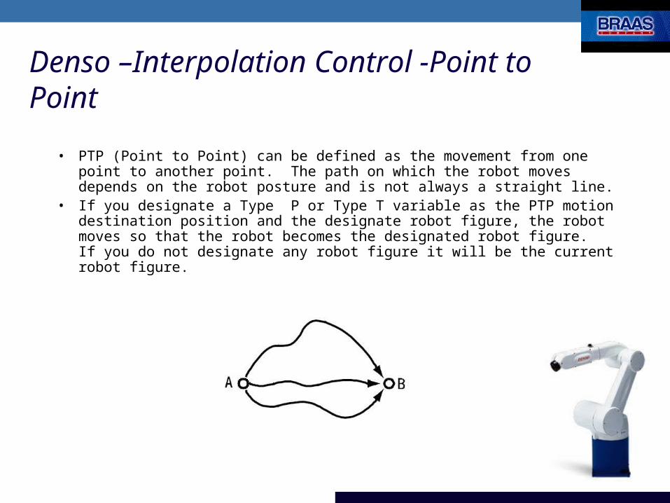
Denso –Interpolation Control -Continuous Path - Linear
• Continuous Path (CP) control manages interpolation so that the path to reach the motion destination position will be a straight line.
• If you designate “L” for designation of the interpolation method with the motion control command, the robot executes the CP motion.
• When CP control is executed, the robot cannot simply move to the position of a different figure. If you designate a different figure a error may occur.
• If the first motion of a program is CP control, the motion may not be available depending on the robot position. PTP control is recommended for the first motion command in the program.

Denso –Interpolation Control - Continuous Path – Circular
(ARC)• ARC interpolation control manages interpolation so that the path
to reach the motion destination position will be an arc.• If you designate “C” for designation of the interpolation method
with the motion control command, the robot executes the ARC motion.
• When CP control is executed, the robot cannot simply move to the position of a different figure. If you designate a different figure an error may occur.
• If the first motion of a program is ARC control, the motion may not be available depending on the robot position. PTP control is recommended for the first motion command in the program.

Denso – Programming Exercise

Denso – Programming Exercise
Pick
P100Place
P101
ApproachPick Point
ApproachPlace Point

Denso – Programming Exercise
Teach two Points into P100 & P101
Access: [F1 Program] – [F4 Variable] –[F4 Position]
P100
P101

Denso – Programming Exercise -Manual• Move between the two Points
– Select the position you want to move to– Make sure motor Power is on– From this screen select [F4 Move]– Select PTP or CP movement – Hold OK button to move
P100
P101

Denso – Programming ExerciseCreate New Program
Access: [F1 Program] – [F1 NewProg.] – [Program OK]

Denso – Programming Exercise
Remove comment mark from TAKEARM
•0001 ‘!TITLE “PRO4”•0002 PROGRAM PRO4•0003 TakeArm•0004•0005 END

Denso - Programming
• TAKEARM (Statement)– Function
• Gets an arm group. Upon the execution of this statement, the programmed speed, acceleration and deceleration will be set to 100. If the gotten arm group includes any robot joint, this statement restores the tool coordinates and work coordinates to the origin.
– Format• TAKEARM[<ArmGroupNumber>][<KEEP=DefaultValue>]
– Note:• TAKEARM command must be issued before any
command that may effect robot arm, Ex: SPEED

Denso – Programming Exercise
Press [F1 New Line] and type APPROACH
•0001 ‘!TITLE “PRO4”•0002 PROGRAM PRO4•0003 TakeArm•0004
•0005 APPROACH P, P1, @0 F1, S=100•0006•0007 END

Denso - Programming
• APPROACH (Statement)– Function
• The robot moves to a position away from the <Base position> by <Approach length> in the Z direction of the tool coordinate system.
– Format • APPROACH <Interpolation method>, <Base position>,
[<Path start displacement>]<Approach length>[,Motion option>][,NEXT]
– Example:• APPROACH P ,P1,@0 F1,S=100

Denso –Confirming Reach Position
• Pass Motion, @P– is to pass the vicinity of a taught motion position or relative
position
• End Motion, @##– is determined if the robot has reached the destination
position when the command value of the servo system meets the destination position.
• Encoder Value Check Motion, @E– is determined when the encoder feedback value is within a
designated window around the destination position.

Denso –Confirming Reach PositionEnd Motion , @##
• PROGRAM END_MOVE– TAKEARM– MOVE L, @11 P2– MOVE L, @E P3– END
11mm
P2
P3
Sp
ee
d
Time
P2 P3

Denso –Confirming Reach PositionPass Motion, @P
• PROGRAM PASS_MOVE– TAKEARM– MOVE P, @P P2– MOVE P, @E P3– END
P2
P3
Sp
ee
d
Time
P2 P3

Denso –Confirming Reach PositionEncoder Check Motion, @E
• PROGRAM ENCODER_MOVE– TAKEARM– MOVE L, @E P2– MOVE L, @E P3– END
P2
P3
Sp
ee
d
Time
P2 P3

Denso – Programming Exercise
Modify APPROACH command as follows:
•0001 ‘!TITLE “PRO4”•0002 PROGRAM PRO4•0003 TakeArm•0004
•0005 APPROACH P, P100, @P 75, S=100•0006•0007 END

Denso – Programming Exercise
Press [F1 New Line] and type MOVE
•0001 ‘!TITLE “PRO4”•0002 PROGRAM PRO4•0003 TakeArm•0004
•0005 APPROACH P, P100, @P 75, S=100•0006 MOVE P, @0 P1, @0 P2, S=100•0007•0008 END

Denso - Programming
• MOVE (Statement)– Function
• Moves the tip of the tool to the specified coordinates.– Format
• MOVE <Interpolation method>,[@<Path start displacement>]<Pose>[,[@<Path start displacement>]<Pose>…][,<Motion option>][,NEXT]
– Examples:• MOVE P, @P P50• MOVE L, @E P1,S=75• MOVE P, @0 (740,0,480,180,0,180,5),NEXT• MOVE C, P100, @P P101

Denso – Programming Exercise
Modify MOVE command as follows:
•0001 ‘!TITLE “PRO4”•0002 PROGRAM PRO4•0003 TakeArm•0004
•0005 APPROACH P, P100, @P 75, S=100•0006 MOVE L, @E P100, S=100•0007•0008 END

Denso – Programming Exercise
Press [F1 New Line] and type RESET
•0001 ‘!TITLE “PRO4”•0002 PROGRAM PRO4•0003 TakeArm•0004
•0005 APPROACH P, P100, @P 75, S=100•0006 MOVE L, @E P100, S=100•0007 RESET IO65•0008•0009 END

Denso - Programming
• RESET (Statement)– Function
• Sets an I/O port to OFF.
– Format • RESET <I/O variable>[,Output time>]
– Example:• RESET IO66

Denso – Programming Exercise
Press [F1 New Line] and type SET
•0001 ‘!TITLE “PRO4”•0002 PROGRAM PRO4•0003 TakeArm•0004
•0005 APPROACH P, P100, @P 75, S=100•0006 MOVE L, @E P100, S=100•0007 RESET IO65•0008 SET IO64•0009•0010 END

Denso - Programming
• SET (Statement)– Function
• Sets an I/O port to ON.
– Format • SET <I/O variable>[,Output time>]
– Example:• SET IO66

Denso – Programming Exercise
Press [F1 New Line] and type DELAY
•0001 ‘!TITLE “PRO4”•0002 PROGRAM PRO4•0003 TakeArm•0004
•0005 APPROACH P, P100, @P 75, S=100•0006 MOVE L, @E P100, S=100•0007 RESET IO65•0008 SET IO64•0009 DELAY 100•0010•0011 END

Denso - Programming
• DELAY (Statement)– Function
• The program processing stops until the time designated by <Delay time> elapses. <Delay time> is expressed in ms, however, the actual delay time changes in increments of 1/60. If multiple tasks are processed at the same time, the delay time may possibly be longer than the designated value.
– Format• DELAY <Delay time>
– Example:• DELAY 120

Denso - Programming
• WAIT (Statement)– Function
• The program processing stops until <Conditional expression> is satisfied. If a <Timeout time> is set, controls stops the execution of a wait statement after the designated time elapses and proceeds to the next command. The WAIT command will assign TRUE(1) or FALSE(0) to the designated <Storage variable> if control passes out of the WAIT by the satisfied <Conditional expression or by timeout.
– Format• WAIT <Conditional expression> [,<Timeout time> [,<Storage variable>]]
– Examples:• WAIT IO10 = ON • WAIT IO134 = OFF, 2000, I1

Denso – Programming Exercise
Press [F1 New Line] and type DEPART
•0001 ‘!TITLE “PRO4”•0002 PROGRAM PRO4•0003 TakeArm•0004
•0005 APPROACH P, P100, @P 75, S=100•0006 MOVE L, @E P100, S=100•0007 RESET IO65•0008 SET IO64•0009 DELAY 100•0010 DEPART P, @0 F1, S=100•0011•0012 END

Denso - Programming
• DEPART (Statement)– Function
• The robot moves by <Depart length> distance from the current position in the Z direction of the tool coordinate system.
– Format • DEPART <Interpolation method>,[<Pass start
displacement>]<Depart length>[,<Motion option>][,NEXT]
– Example:• DEPART L,125,S=F123

Denso – Programming Exercise
Modify DEPART command as follows:
•0001 ‘!TITLE “PRO4”•0002 PROGRAM PRO4•0003 TakeArm•0004
•0005 APPROACH P, P100, @P 75, S=100•0006 MOVE L, @E P100, S=100•0007 RESET IO65•0008 SET IO64•0009 DELAY 100•0010 DEPART L, @0 75, S=100•0011•0012 END

Denso – Programming Exercise
Highlight the APPROACH command, press and hold the shift key, scroll down to the DEPART command.
•0001 ‘!TITLE “PRO4”•0002 PROGRAM PRO4•0003 TakeArm•0004
•0005 •0006•0007•0008•0009•0010•0011•0012 END
APPROACH P, P100, @P 75, S=100MOVE L, @E P100, S=100RESET IO65SET IO64DELAY 100DEPART L, @0 75, S=100

Denso – Programming ExerciseWith the DEPART command highlighted, press copy, then press paste.
•0001 ‘!TITLE “PRO4”•0002 PROGRAM PRO4•0003 TakeArm•0004
•0005 APPROACH P, P100, @P 75, S=100•0006 MOVE L, @E P100, S=100•0007 RESET IO65•0008 SET IO64•0009 DELAY 100•0010 DEPART L, @0 75, S=100•0011 APPROACH P, P100, @P 75, S=100•0012 MOVE L, @E P100, S=100•0013 RESET IO65•0014 SET IO64•0015 DELAY 100•0016 DEPART L, @0 75, S=100•0017•0018 END

Denso – Programming ExerciseModify the program to match the following:
•0001 ‘!TITLE “PRO4”•0002 PROGRAM PRO4•0003 TakeArm•0004
•0005 APPROACH P, P100, @P 75, S=100•0006 MOVE L, @E P100, S=100•0007 RESET IO65•0008 SET IO64•0009 DELAY 100•0010 DEPART L, @0 75, S=100•0011 APPROACH P, P101, @0 75, S=100•0012 MOVE L, @0 P101, S=100•0013 RESET IO64•0014 SET IO65•0015 DELAY 100•0016 DEPART L, @P 75, S=100•0017•0018 END

Denso – Programming Exercise• Save Program (F6)
• Compile Program (From Program list, “Config”; “Make the specified program active?”, ”OK”; Do you want compile?, “OK”)
• Set the Robot control to run off the pendant vs. PLC. – Cancel to the Top Screen– Set Pendant to Manual Mode– [F4 IO] – [F6 Aux] –[F1 Set H/W]– Set Parameter 31 “Single Point of Control” to Internal (0)

Denso – Programming Exercise- Teach Check
• Set hardwired ‘Enable Auto” Switch to Manual• Hold deadman switch on• Press “Motor” button to enable servos on Robot• Set the Pendant to TEACHCHECK Mode• Select the program from the Program List• [F4-CycStart]• To make motion press and hold the “OK”
– If you release the “OK” button, repeat steps 13 thru 15.

Denso – Programming Exercise- Auto
• Set hardwired ‘Enable Auto” Switch to Auto• Set the pendant to AUTO• Press “Motor” button to enable servos on Robot• Select the program from the Program List• [F4-Start]• Select “Single-Cycle” or “Continuously”

Denso – Programming Exercise-Cycle Time
• Monitoring Cycle Time– To Enable:
• [F1 Program] [F6 Aux.] [F1 Set PRJ]• Parameter 14 – Delete cycle time calculation code
– 0 Measure the run time of all programs
– 1 Measure the run time of programs in the folder, that can be called through IO. (Roots are named “PRO*”)
– 2 Do not measure the run time of programs.

Denso Training - Agenda
• Hardware Overview• Jogging the robot• Teaching Positions (using the Teach Pendant)• Configuring the Robot• Programming (Using the Teach Pendant)• I/O Interfacing (Hardware)• Overview of Development Software• Maintenance

Denso – Control Interfaces
• Safety I/O• Hardwired Handshake
– Standard– Optional Expansion IO
• DeviceNet• Ethernet/IP• Operator Panel

Denso – I/O Command Details
• To determine which documentation to use look for Hardware Type and I/O Mode.
HardwareType
GlobalUS & Europe
StandardJapan Only
I/OMode
CompatibleOLD RC3
StandardRC7

Denso -Safety I/O Connector
• E-Stops must be made for Manual, Teach-Check and Auto modes.
• The Protective Stop and Enable Auto inputs must be made for Automatic operation.

Denso -Safety I/O Connector
Each row is a twisted pair in the cable.

Denso –Mini I/O ConnectorInternal / External Power
• The default wiring is for an external 24VDC supply on the Mini I/O Connector.

Denso – I/O Command Details

Denso – I/O Command Details

Denso – I/O Command Details – w/Parallel I/O

Denso – I/O Allocation

Denso – DeviceNet
• DeviceNet Option Card – May be ordered with the controller (Recommended) or field
installed.– Slave Board, Master Board, Master/Slave Board options– Uses the Extended Command area & Data area
implementation• Same as the Expansion IO approach • Same as the RC5 DeviceNet Implementation
DeviceNet
PLC

Denso – DeviceNet
• Ethernet/IP Option Card – May be ordered with the controller (Recommended) or field
installed.– Slave Board only– Uses the Extended Command area & Data area
implementation• Same as the Expansion IO approach
Ethernet/IP
PLC

Denso – Operator Panel
• The operator panel is a feature of the operator pendant. It allows the pendant to be used as an operator interface for the robot.
Access: [F5 OpePanel] Exit: [[Shift]-[Cancel]]

Denso Training - Agenda
• Hardware Overview• Jogging the robot• Teaching Positions (using the Teach Pendant)• Configuring the Robot• Programming (Using the Teach Pendant)• I/O Interfacing (Hardware)• Overview of Development Software• Maintenance

Denso –Software – WinCaps III

Denso – Software
• Always upload Robot Configuration from the controller before doing any programming!
• Save the settings from the factory and the last programs, so that you can restore what you had.
Robot controller

Denso – Software – Project Wizard
• Wizard for setting up the application

Denso –Software – Variable View

Denso –Software -DIO View

Denso – Software – Arm View

Denso –Software – WinCaps III - CAD Import

Denso –Software -ArmPlayerPlus
• Robot simulation software• Allows the user to:
– Visually see the robot cycle– Determine the execution
time of a program cycle– Step thru the program to
see the time for each step– Build a trial program

Denso –Software -ArmPlayerPlus
• ArmPlayerPlus -Simulate the robot moving between multiple points and determine the cycle time.

Denso – Software - Error LogAccess: [F6 –Set] [F2 –Log.] [F1 -ErrLog]
Document: error-e.pdf

Denso – Software - Operation LogAccess: [F6 –Set] [F2 –Log.] [F2 -OprLog]

Denso – Maintenance Access: [F6 –Set] [F6-Maint.]

Denso – Maintenance Access: [F6 –Set] [F6-Maint.]

Denso – Robot Training
• Thank you!
Please fill out the evaluation.

Denso – Appendix A –Collision Detection
• Example Collision Detection Components – Used on Demo Cell
– Part Number Quantity Description– QSAP-25AISOBC31.5 1 Denso VS6556 to QS25 Adapter– QS-25ANP-T3 1 Applied Robotics Quickstop– 98506-C103A 1 PAK-QS25A/CXC10 Adapter– CXC10R-00-06-NP 1 AR Robot Tool Adapter Unit– CXC10T-00-06-NP 2 AR Tool Adapter Unit– CXC10F-18-150-S 2 AR Tool Support Fixture Plate– CXC10UAP-BP 2 AR Product Adapter Kit