
BPS 34 EN - leuze.com · General information. Leuze electronic. 4 BPS 34 Leuze electronic. 1.3...
108
Leuze electronic Barcode positioning system BPS 34 for the PROFIBUS DP Technical Description
Transcript of BPS 34 EN - leuze.com · General information. Leuze electronic. 4 BPS 34 Leuze electronic. 1.3...
Leuze electronic
Barcode positioning system BPS 34 for the PROFIBUS DP
Technical Description

© All rights reserved, especially the right of reproduction and translation. This document may not be duplicated or reproduced in any form without the written permission of Leuze electronic GmbH + Co. KG It is subject to changes due to technical progress.
Leuze electronic BPS 34 1
Leuze electronic Table of contents
1 General information........................................................................................................... 3
1.1 Explanation of symbols ........................................................................................................ 31.2 Declaration of conformity ..................................................................................................... 31.3 Description of the BPS 34 functions .................................................................................... 4
2 Safety notices..................................................................................................................... 5
2.1 General safety notices ......................................................................................................... 52.2 Safety standards .................................................................................................................. 52.3 Intended use ........................................................................................................................ 52.4 Working safely ..................................................................................................................... 6
3 Commissioning steps at a glance .................................................................................... 8
4 Specifications BPS 34 ..................................................................................................... 13
4.1 General specifications BPS 34 .......................................................................................... 134.2 Dimensioned drawings....................................................................................................... 144.3 Electrical connection .......................................................................................................... 164.3.1 PWR IN - voltage supply and switching input/output ................................................................... 184.3.2 DP IN - PROFIBUS DP incoming ................................................................................................ 194.3.3 DP OUT - PROFIBUS DP outgoing............................................................................................. 194.3.4 SW IN/OUT - switching input/switching output ............................................................................ 204.3.5 BPS 34 reading field curve .......................................................................................................... 21
5 Connector units MS 34 … / MSD 1 101........................................................................... 22
5.1 Modular hoods with integrated connectors MS 34 103 and MS 34 105 ............................ 225.1.1 General information ..................................................................................................................... 225.1.2 Specifications of the connector units ........................................................................................... 225.1.3 Dimensioned drawings ................................................................................................................ 235.1.4 Electrical connection.................................................................................................................... 245.1.5 Description of the LED states ...................................................................................................... 245.2 Modular Service Display MSD 1 101 ................................................................................. 255.2.1 General information ..................................................................................................................... 255.2.2 Dimensioned drawing .................................................................................................................. 265.2.3 Electrical connection.................................................................................................................... 26
6 Barcode tape .................................................................................................................... 27
6.1 General information ........................................................................................................... 276.2 Specifications of the barcode tape..................................................................................... 286.3 Mounting the barcode tape ................................................................................................ 296.4 Control barcode ................................................................................................................. 326.4.1 Controllable functions .................................................................................................................. 336.5 Repair kit ............................................................................................................................ 35
7 Mounting........................................................................................................................... 37
7.1 Mounting the BPS 34 ......................................................................................................... 377.2 Device arrangement........................................................................................................... 407.3 Mounting the barcode tape ................................................................................................ 41
2 BPS 34 Leuze electronic
Table of contents Leuze electronic
8 Device parameters and interfaces.................................................................................. 42
8.1 PROFIBUS......................................................................................................................... 428.1.1 General information......................................................................................................................428.1.2 Electrical connection ....................................................................................................................428.1.3 PROFIBUS address .....................................................................................................................458.1.4 General information on the GSE file ............................................................................................458.1.5 Structure of the GSE modules .....................................................................................................468.1.6 Overview of the GSE modules .....................................................................................................478.1.7 Detailed description of the modules .............................................................................................50
9 Diagnostics and troubleshooting................................................................................... 92
9.1 General causes of errors ................................................................................................... 929.2 PROFIBUS errors .............................................................................................................. 92
10 Type overview and accessories ..................................................................................... 94
10.1 Type overview: BPS 34...................................................................................................... 9410.2 Accessory modular hoods with integrated connectors....................................................... 9410.3 Accessory modular service display.................................................................................... 9410.4 Accessory termination........................................................................................................ 9410.5 Accessory connectors........................................................................................................ 9410.6 Accessory mounting device ............................................................................................... 9410.7 Accessory ready-made cables for voltage supply.............................................................. 9510.7.1 Contact assignment of PWR IN connection cable........................................................................9510.7.2 Specifications of voltage supply cable .........................................................................................9510.7.3 Order codes for voltage supply cables .........................................................................................9510.8 Accessory ready-made cables for PROFIBUS connection................................................ 9610.8.1 General ........................................................................................................................................9610.8.2 Contact assignment for PROFIBUS connection cable KB PB…..................................................9610.8.3 Specifications of PROFIBUS connection cable............................................................................9710.8.4 Order codes for PROFIBUS connection cables ...........................................................................9710.9 Type overview: Barcode tape ............................................................................................ 98
11 Maintenance ..................................................................................................................... 99
11.1 General maintenance information...................................................................................... 9911.2 Repairs, servicing .............................................................................................................. 9911.3 Disassembling, packing, disposing .................................................................................... 99
12 Appendix......................................................................................................................... 100
12.1 EU Declaration of Conformity .......................................................................................... 100

Leuze electronic General information
Leuze electronic BPS 34 3
TN
T 3
5/7-
24V
1 General information
1.1 Explanation of symbolsThe symbols used in this operating manual are explained below.
Attention!This symbol appears before text passages which must absolutely be observed. Failure to heed this information can lead to injuries to personnel or damage to the equipment.
Attention Laser!This symbol warns of possible danger through hazardous laser radiation.
Notice!This symbol indicates text passages containing important information.
1.2 Declaration of conformityThe barcode positioning system BPS 34, the modular hood with integrated connectors MS 34 103/MS 34 105, and the optional modular service display MSD 1 101 have been developed and manufactured under observation of the applicable European standards and directives.
The devices of the BPS 34 series also fulfil the cUL requirements (Underwriters Laboratory Inc.) for the USA and Canada.
Notice!A copy of all declarations of conformity available for the product can be found in the appen-dix of this handbook (see chapter 12.1 "EU Declaration of Conformity" on page 100).
The manufacturer of the product, Leuze electronic GmbH + Co. KG in D-73277 Owen/Teck, possesses a certified quality assurance system in accordance with ISO 9001.
UL USC
LISTED
General information Leuze electronic
4 BPS 34 Leuze electronic
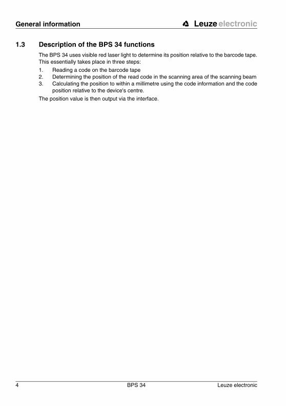
1.3 Description of the BPS 34 functionsThe BPS 34 uses visible red laser light to determine its position relative to the barcode tape. This essentially takes place in three steps:
1. Reading a code on the barcode tape2. Determining the position of the read code in the scanning area of the scanning beam3. Calculating the position to within a millimetre using the code information and the code
position relative to the device's centre.
The position value is then output via the interface.
Leuze electronic Safety notices
Leuze electronic BPS 34 5
TN
T 3
5/7-
24V
2 Safety notices
2.1 General safety notices
DocumentationAll entries in this technical description must be heeded, in particular those in section "Safety notices". Keep this technical description in a safe place. It should be accessible at all times.
Safety regulationsObserve the locally applicable legal regulations and the rules of the employer's liability insur-ance association.
RepairRepairs must only be carried out by the manufacturer or an authorised representative.
2.2 Safety standardsThe devices of the BPS 34 series were developed, manufactured and tested in accordance with the applicable safety standards. They correspond to the state of the art.
2.3 Intended useBarcode positioning systems of the BPS 34 series are optical measuring systems which use visible red laser light to determine the position of the BPS relative to a permanently mounted barcode tape.
The modular hoods with integrated connectors MS 34 103/MS 34 105 are intended for the easy connection of barcode positioning systems of type BPS 34 in a PROFIBUS system.
The modular service display MSD 1 101, which is optionally available, displays operational data of the BPS 34 and is used as a simple means of access to the service interface of the MS 34 105.
In particular, unauthorised uses include:
• rooms with explosive atmospheres • operation for medical purposes
Attention!The protection of personnel and the device is guaranteed only if the device is operated in a manner corresponding to its intended use.
Safety notices Leuze electronic
6 BPS 34 Leuze electronic
Areas of applicationThe barcode positioning system BPS 34 has been developed for positioning tasks in the following areas of application:
• High-bay storage devices: Positioning in the travel and lifting axes• Crane bridges and trolleys• Side-tracking skates• Telpher lines• Lifts
2.4 Working safely
Attention!Access to or changes on the device, except where expressly described in this operating manual, are not authorised.
Safety RegulationsObserve the locally applicable legal regulations and the rules of the employer's liability insur-ance association.
Qualified personnelMounting, commissioning and maintenance of the device may only be carried out by quali-fied personnel. Electrical work must be carried out by a certified electrician.
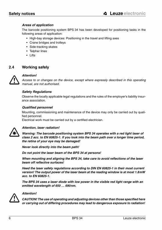
Attention, laser radiation!
Warning: The barcode positioning system BPS 34 operates with a red light laser of class 2 acc. to EN 60825-1. If you look into the beam path over a longer time period, the retina of your eye may be damaged!
Never look directly into the beam path!
Do not point the laser beam of the BPS 34 at persons!
When mounting and aligning the BPS 34, take care to avoid reflections of the laser beam off reflective surfaces!
Heed the laser safety regulations according to DIN EN 60825-1 in their most current version! The output power of the laser beam at the reading window is at most 1.8 mW acc. to EN 60825-1.
The BPS 34 uses a laser diode with low power in the visible red light range with an emitted wavelength of 650 … 690 nm.
Attention!
CAUTION! The use of operating and adjusting devices other than those specified here or carrying out of differing procedures may lead to dangerous exposure to radiation!
Leuze electronic Safety notices
Leuze electronic BPS 34 7
TN
T 3
5/7-
24V
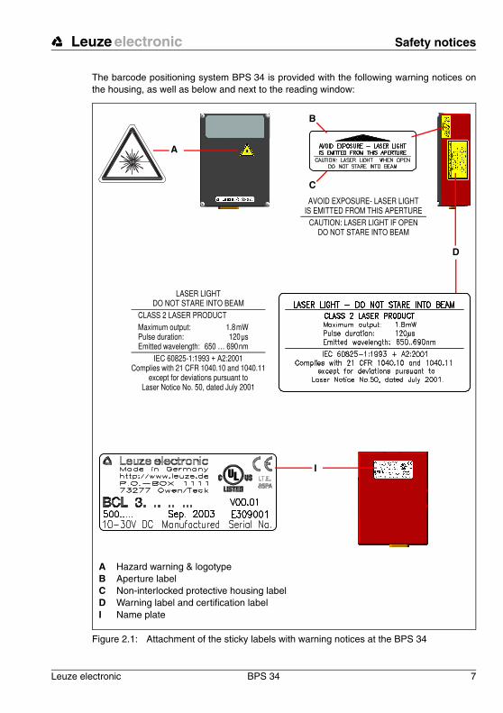
The barcode positioning system BPS 34 is provided with the following warning notices on the housing, as well as below and next to the reading window:
Figure 2.1: Attachment of the sticky labels with warning notices at the BPS 34
A
B
D
I
C
A Hazard warning & logotypeB Aperture labelC Non-interlocked protective housing labelD Warning label and certification labelI Name plate
LASER LIGHTDO NOT STARE INTO BEAM
CLASS 2 LASER PRODUCTMaximum output: 1.8 mW Pulse duration: 120 µs Emitted wavelength: 650 … 690 nm
IEC 60825-1:1993 + A2:2001Complies with 21 CFR 1040.10 and 1040.11
except for deviations pursuant toLaser Notice No. 50, dated July 2001
AVOID EXPOSURE- LASER LIGHT IS EMITTED FROM THIS APERTURE
CAUTION: LASER LIGHT IF OPENDO NOT STARE INTO BEAM
Commissioning steps at a glance Leuze electronic
8 BPS 34 Leuze electronic
3 Commissioning steps at a glance
Notice!Below you will find a short description for the initial commissioning of the barcode po-sitioning system BPS 34. Detailed explanations for all listed points can be found throughout the handbook.
Mechanical design
Mounting the barcode tape The barcode tape is to be affixed without tension to a dust- and grease-free mounting surface.
➔ chapter 6.3 on page 29
Mounting the BPS 34 deviceThere are two different types of mounting arrangements for the BPS 34:
1. Using 4 M4x6 screws on the rear of the device.2. Using a mounting device (BT 56) on the dovetail fastening grooves.
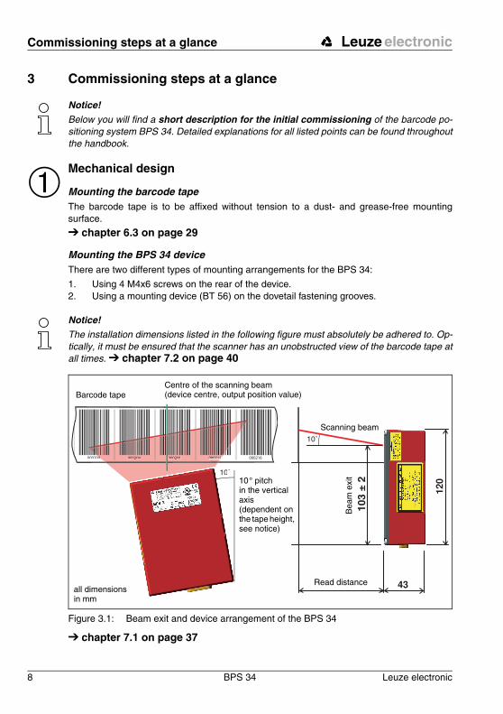
Notice!The installation dimensions listed in the following figure must absolutely be adhered to. Op-tically, it must be ensured that the scanner has an unobstructed view of the barcode tape at all times. ➔ chapter 7.2 on page 40
Figure 3.1: Beam exit and device arrangement of the BPS 34
➔ chapter 7.1 on page 37
➀
000200 2 0002160 000204 000208 0002122
10˚
103
± 2
10˚
Read distance
Bea
m e
xit
all dimensions in mm
Barcode tapeCentre of the scanning beam(device centre, output position value)
Scanning beam
10 ° pitch in the vertical axis (dependent on the tape height, see notice)
Leuze electronic Commissioning steps at a glance
Leuze electronic BPS 34 9
TN
T 3
5/7-
24V
Notice!During mounting, the following angles of inclination must be taken into account in the vertical axis: 10 ° for a tape height of 47 mm, 7 ° for a tape height of 30 mm and 5 ° for a tape height of 25 mm; the working range of the reading field curve must also be tak-en into account.
Attention!For the position calculation, the scanning beam of the BPS 34 must be incident on the bar-code tape without interruption. Ensure that the scanning beam is always incident on the bar-code tape when the system is moving.
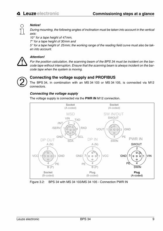
Connecting the voltage supply and PROFIBUSThe BPS 34, in combination with an MS 34 103 or MS 34 105, is connected via M12 connectors.
Connecting the voltage supplyThe voltage supply is connected via the PWR IN M 12 connection.
Figure 3.2: BPS 34 with MS 34 103/MS 34 105 - Connection PWR IN
➁
Socket(A-coded)
Socket(A-coded)
Socket(B-coded)
Plug(B-coded)
Plug(A-coded)
PWR IN
SWIN
SWOUT
3
2
1
4
GND VIN
PE
SW IN/OUT
1
2
3
4
VOUT
PE
SWIN
SWOUT
GND
DP IN
GND 3
2
1
4PE
A (N)
B (P)
VCC
DP OUT
VCC 1
2
3
4
A (N)
B (P)
GND
PE
1
2 3
4
MSD
56
7
/SERV
VINTXD
RXD
SCL
SDA
GND
/INT
Commissioning steps at a glance Leuze electronic
10 BPS 34 Leuze electronic
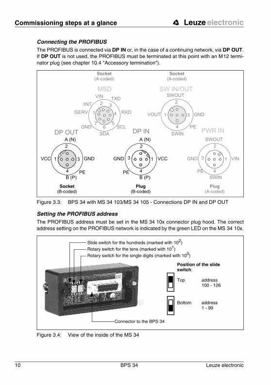
Connecting the PROFIBUSThe PROFIBUS is connected via DP IN or, in the case of a continuing network, via DP OUT. If DP OUT is not used, the PROFIBUS must be terminated at this point with an M 12 termi-nator plug (see chapter 10.4 "Accessory termination").
Figure 3.3: BPS 34 with MS 34 103/MS 34 105 - Connections DP IN and DP OUT
Setting the PROFIBUS addressThe PROFIBUS address must be set in the MS 34 10x connector plug hood. The correct address setting on the PROFIBUS network is indicated by the green LED on the MS 34 10x.
Figure 3.4: View of the inside of the MS 34
Socket(A-coded)
Socket(A-coded)
Socket(B-coded)
Plug(B-coded)
Plug(A-coded)
DP IN
GND 3
2
1
4PE
A (N)
B (P)
VCC
DP OUT
VCC 1
2
3
4
A (N)
B (P)
GND
PE
PWR IN
SWIN
SWOUT
3
2
1
4
GND VIN
PE
SW IN/OUT
1
2
3
4
VOUT
PE
SWIN
SWOUT
GND1
2 3
4
MSD
56
7
/SERV
VINTXD
RXD
SCL
SDA
GND
/INT
Slide switch for the hundreds (marked with 102)Rotary switch for the tens (marked with 101)Rotary switch for the single digits (marked with 100)
Connector to the BPS 34
Position of the slide switch:
Top address100 - 126
Bottom address1 - 99
Leuze electronic Commissioning steps at a glance
Leuze electronic BPS 34 11
TN
T 3
5/7-
24V
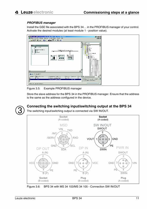
PROFIBUS managerInstall the GSE file associated with the BPS 34… in the PROFIBUS manager of your control. Activate the desired modules (at least module 1 - position value).
Figure 3.5: Example PROFIBUS manager
Store the slave address for the BPS 34 in the PROFIBUS manager. Ensure that the address is the same as the address configured in the device.
Connecting the switching input/switching output at the BPS 34The switching input/switching output is connected via SW IN/OUT.
Figure 3.6: BPS 34 with MS 34 103/MS 34 105 - Connection SW IN/OUT
➂Socket
(A-coded)Socket
(A-coded)
Socket(B-coded)
Plug(B-coded)
Plug(A-coded)
SW IN/OUT
1
2
3
4
VOUT
PE
SWIN
SWOUT
GND
PWR IN
SWIN
SWOUT
3
2
1
4
GND VIN
PE
DP IN
GND 3
2
1
4PE
A (N)
B (P)
VCC
DP OUT
VCC 1
2
3
4
A (N)
B (P)
GND
PE
1
2 3
4
MSD
56
7
/SERV
VINTXD
RXD
SCL
SDA
GND
/INT
Commissioning steps at a glance Leuze electronic
12 BPS 34 Leuze electronic
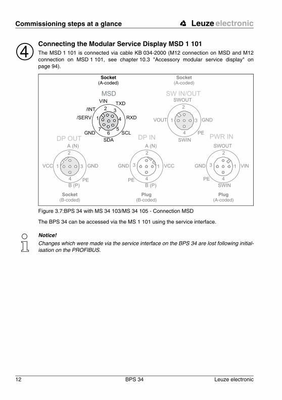
Connecting the Modular Service Display MSD 1 101The MSD 1 101 is connected via cable KB 034-2000 (M12 connection on MSD and M12 connection on MSD 1 101, see chapter 10.3 "Accessory modular service display" on page 94).
Figure 3.7:BPS 34 with MS 34 103/MS 34 105 - Connection MSD
The BPS 34 can be accessed via the MS 1 101 using the service interface.
Notice!Changes which were made via the service interface on the BPS 34 are lost following initial-isation on the PROFIBUS.
➃Socket
(A-coded)Socket
(A-coded)
Socket(B-coded)
Plug(B-coded)
Plug(A-coded)
1
2 3
4
MSD
56
7
/SERV
VINTXD
RXD
SCL
SDA
GND
/INT
PWR IN
SWIN
SWOUT
3
2
1
4
GND VIN
PE
SW IN/OUT
1
2
3
4
VOUT
PE
SWIN
SWOUT
GND
DP IN
GND 3
2
1
4PE
A (N)
B (P)
VCC
DP OUT
VCC 1
2
3
4
A (N)
B (P)
GND
PE
Leuze electronic Specifications BPS 34
Leuze electronic BPS 34 13
TN
T 3
5/7-
24V
4 Specifications BPS 34
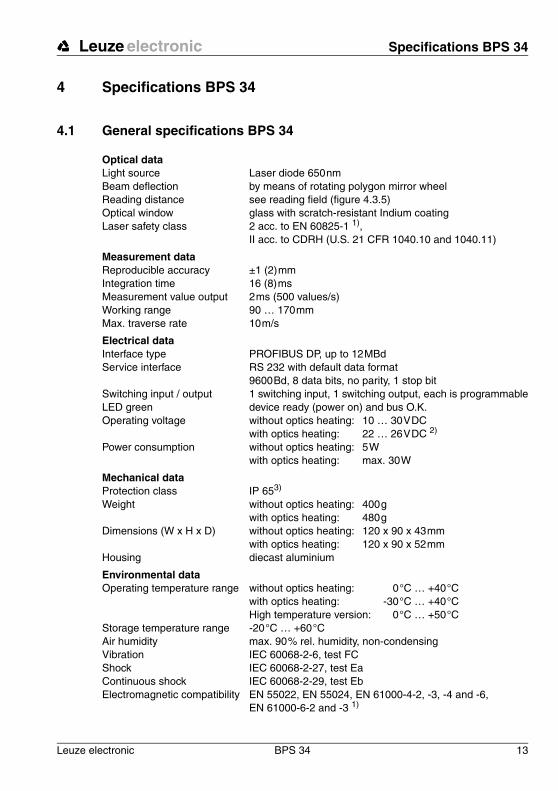
4.1 General specifications BPS 34
Optical dataLight source Laser diode 650 nmBeam deflection by means of rotating polygon mirror wheelReading distance see reading field (figure 4.3.5)Optical window glass with scratch-resistant Indium coatingLaser safety class 2 acc. to EN 60825-1 1),
II acc. to CDRH (U.S. 21 CFR 1040.10 and 1040.11)
Measurement dataReproducible accuracy ±1 (2) mmIntegration time 16 (8) msMeasurement value output 2 ms (500 values/s)Working range 90 … 170 mmMax. traverse rate 10 m/s
Electrical dataInterface type PROFIBUS DP, up to 12 MBdService interface RS 232 with default data format
9600 Bd, 8 data bits, no parity, 1 stop bitSwitching input / output 1 switching input, 1 switching output, each is programmableLED green device ready (power on) and bus O.K.Operating voltage without optics heating: 10 … 30 V DC
with optics heating: 22 … 26 V DC 2)
Power consumption without optics heating: 5 Wwith optics heating: max. 30 W
Mechanical dataProtection class IP 653)
Weight without optics heating: 400 gwith optics heating: 480 g
Dimensions (W x H x D) without optics heating: 120 x 90 x 43 mmwith optics heating: 120 x 90 x 52 mm
Housing diecast aluminium
Environmental dataOperating temperature range without optics heating: 0 °C … +40 °C
with optics heating: -30 °C … +40 °C High temperature version: 0 °C … +50 °C
Storage temperature range -20 °C … +60 °CAir humidity max. 90 % rel. humidity, non-condensing Vibration IEC 60068-2-6, test FCShock IEC 60068-2-27, test EaContinuous shock IEC 60068-2-29, test EbElectromagnetic compatibility EN 55022, EN 55024, EN 61000-4-2, -3, -4 and -6,
EN 61000-6-2 and -3 1)
Specifications BPS 34 Leuze electronic
14 BPS 34 Leuze electronic
Table 4.1: General specifications
Notice!The warm-up time before devices with integrated heating are ready for operation is approx. 30 min. (depending on the environmental conditions).
For devices with integrated heating (…H models), window heating is in constant operation. Regulation of device-internal heating is temperature dependent.
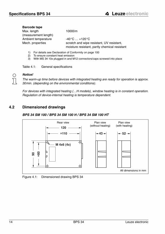
4.2 Dimensioned drawings
BPS 34 SM 100 / BPS 34 SM 100 H / BPS 34 SM 100 HT
Figure 4.1: Dimensioned drawing BPS 34
Barcode tapeMax. length (measurement length)
10000 m
Ambient temperature -40 °C … +120 °CMech. properties scratch and wipe resistant, UV resistant,
moisture resistant, partly chemical resistant
1) For details see Declaration of Conformity on page 1002) To ensure constant heat emission3) With MS 34 10x plugged in and M12 connectors/caps screwed into place
Plan view(without heating)
Rear view
All dimensions in mm
Plan view(with heating)
Leuze electronic Specifications BPS 34
Leuze electronic BPS 34 15
TN
T 3
5/7-
24V
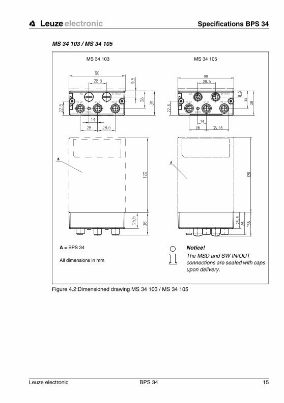
MS 34 103 / MS 34 105
Figure 4.2:Dimensioned drawing MS 34 103 / MS 34 105
MS 34 105MS 34 103
A = BPS 34
All dimensions in mm
Notice!The MSD and SW IN/OUT connections are sealed with caps upon delivery.
Specifications BPS 34 Leuze electronic
16 BPS 34 Leuze electronic
4.3 Electrical connectionThe BPS 34 can be connected via the MS 34 103/MS 34 105 using M12 connectors. For the locations of the individual device connections, please refer to the device detail shown in figure 4.3.
The corresponding mating connectors and ready-made cables are available as accessories for all connections. For additional information, refer to chapter 10 starting on page 94.
Attention!Connection of the device and cleaning must only be carried out by a qualified electrician.
If faults cannot be corrected, the device should be removed from operation and protected against possible use.
Before connecting the device, be sure that the supply voltage agrees with the value printed on the name plate.
The power supply unit for the generation of the supply voltage for the BPS 34 and the re-spective connection units must have a secure electrical insulation through double insulation and safety transformers according to EN 60742 (corresponds to IEC 60742).
Be sure that the protective conductor is connected correctly. Error-free operation is only guaranteed if the device is properly earthed.

Leuze electronic Specifications BPS 34
Leuze electronic BPS 34 17
TN
T 3
5/7-
24V
Figure 4.3:Connection assignment of the BPS 34 with MS 34 103 / MS 34 105
Attention!Protection class IP 65 is achieved only if the connectors and caps are screwed into place!
PWR IN = voltage supplyDP IN = PROFIBUS INDP OUT = PROFIBUS OUTMSD = Modular Service Display (MS 34 105 only)SW IN/OUT = switching input/output (MS 34 105 only)
Notice!The MSD and SW IN/OUT connections are sealed with caps upon delivery.
Socket(A-coded)
Socket(A-coded)
Socket(B-coded)
Plug(B-coded)
Plug(A-coded)
1
2 3
4
DP IN
SW IN/OUT
PWR IN
1
2
3
4
VOUT
SWIN
GND
SWOUT
PE
3
2
1
4
GND VIN
PE
DP OUT
MSD
SWIN
SWOUT
3
2
1
4
GND
VCC
PE
1
2
3
4
A (N)
B (P)
A (N)
B (P)
VCCGND
PE
56
7
/SERV
VINTXD
RXD
SCL
SDA
GND
/INT
All dimensions in mm
Specifications BPS 34 Leuze electronic
18 BPS 34 Leuze electronic
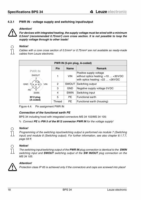
4.3.1 PWR IN - voltage supply and switching input/output
Attention!For devices with integrated heating, the supply voltage must be wired with a minimum 0.5 mm² (recommended 0.75 mm²) core cross section. It is not possible to loop the supply voltage through to other loads!
Notice!Cables with a core cross section of 0.5 mm² or 0.75 mm² are not available as ready-made cables from Leuze electronic.
Figure 4.4: Pin assignment PWR IN
Connection of the functional earth PEBPS 34 including hood with integrated connectors MS 34 103/MS 34 105:
! Connect PE to PIN 5 of the M 12 connector PWR IN for the voltage supply!
Notice!Programming of the switching input/switching output is performed via module 7 (Switching input) and module 8 (Switching output). For further information, see also chapter 8.1.7.7, page 59 ff.
Notice!The switching input/switching output of the PWR IN plug connection is identical to the SWINswitching input and SWOUT switching output of the SW IN/OUT plug connection on the MS 34 105.
Attention!Protection class IP 65 is achieved only if the connectors and caps are screwed into place!
PWR IN (5-pin plug, A-coded)
Pin Name Remark
1 VINPositive supply voltage without optics heating: +10 … +30 V DCwith optics heating: +22 … +26 V DC
2 SWOUT Switching output
3 GND Negative supply voltage 0 V DC
4 SWIN Switching input
5 PE Functional earth
Thread PE Functional earth (housing)
PWR IN
SWIN
SWOUT
3
2
1
4
GND VIN
PE
M 12 plug(A-coded)

Leuze electronic Specifications BPS 34
Leuze electronic BPS 34 19
TN
T 3
5/7-
24V
4.3.2 DP IN - PROFIBUS DP incoming
Figure 4.5: Pin assignment DP IN
Attention!Protection class IP 65 is achieved only if the connectors and caps are screwed into place!
4.3.3 DP OUT - PROFIBUS DP outgoing
Figure 4.6: Pin assignment DP IN
Attention!Protection class IP 65 is achieved only if the connectors and caps are screwed into place!
Notice!If the PROFIBUS is not connected to another subscriber via the MS 34 10x, the DP OUT connection must be fitted with a TS 02-4-SA terminator plug for the purpose of bus termina-tion. For further information, see also chapter 10.4 on page 94.
DP IN (5-pin plug, B-coded)
Pin Name Remark
1 VCC 5 V DC for bus termination
2 A (N) Receive/transmit data A-line (N)
3 GND Functional earth for bus termination
4 B (P) Receive/transmit data B-line (P)
5 PE Functional earth
Thread PE Functional earth (housing)
DP IN
GND 3
2
1
4PE
A (N)
B (P)
VCC
M 12 plug(B-coded)
DPOUT (5-pin socket, B-coded)
Pin Name Remark
1 VCC 5 V DC for bus termination
2 A (N) Receive/transmit data A-line (N)
3 GND Functional earth for bus termination
4 B (P) Receive/transmit data B-line (P)
5 PE Functional earth
Thread PE Functional earth (housing)
DP OUT
VCC 1
2
3
4
A (N)
B (P)
GND
PE
M 12 socket(B-coded)
Specifications BPS 34 Leuze electronic
20 BPS 34 Leuze electronic
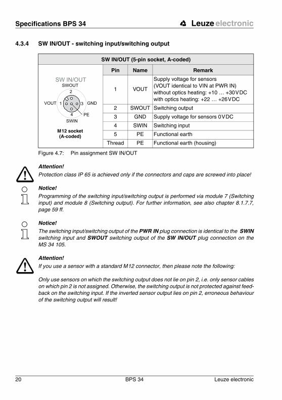
4.3.4 SW IN/OUT - switching input/switching output
Figure 4.7: Pin assignment SW IN/OUT
Attention!Protection class IP 65 is achieved only if the connectors and caps are screwed into place!
Notice!Programming of the switching input/switching output is performed via module 7 (Switching input) and module 8 (Switching output). For further information, see also chapter 8.1.7.7, page 59 ff.
Notice!The switching input/switching output of the PWR IN plug connection is identical to the SWINswitching input and SWOUT switching output of the SW IN/OUT plug connection on the MS 34 105.
Attention!If you use a sensor with a standard M 12 connector, then please note the following:
Only use sensors on which the switching output does not lie on pin 2, i.e. only sensor cables on which pin 2 is not assigned. Otherwise, the switching output is not protected against feed-back on the switching input. If the inverted sensor output lies on pin 2, erroneous behaviour of the switching output will result!
SW IN/OUT (5-pin socket, A-coded)
Pin Name Remark
1 VOUT
Supply voltage for sensors (VOUT identical to VIN at PWR IN) without optics heating: +10 … +30 V DCwith optics heating: +22 … +26 V DC
2 SWOUT Switching output
3 GND Supply voltage for sensors 0 V DC
4 SWIN Switching input
5 PE Functional earth
Thread PE Functional earth (housing)
SW IN/OUT
1
2
3
4
VOUT
PE
SWIN
SWOUT
GND
M 12 socket(A-coded)
Leuze electronic Specifications BPS 34
Leuze electronic BPS 34 21
TN
T 3
5/7-
24V
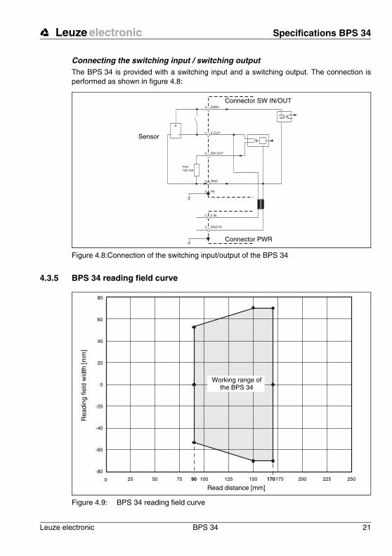
Connecting the switching input / switching outputThe BPS 34 is provided with a switching input and a switching output. The connection is performed as shown in figure 4.8:
Figure 4.8:Connection of the switching input/output of the BPS 34
4.3.5 BPS 34 reading field curve
Figure 4.9: BPS 34 reading field curve
SWIN4
V OUT1
GND3
PE5
SW OUT2
max. 100 mA
GND IN3
V IN1
A
Sensor
Connector SW IN/OUT
Connector PWR
-80
-60
-40
-20
0
20
40
60
80
0 25 75 125 17550 100 17090 150 200 250225
Read distance [mm]
Rea
ding
fiel
d w
idth
[mm
]
Working range of the BPS 34

Connector units MS 34 … / MSD 1 101 Leuze electronic
22 BPS 34 Leuze electronic
5 Connector units MS 34 … / MSD 1 101
5.1 Modular hoods with integrated connectors MS 34 103 and MS 34 105A modular hood of type MS 34 103 or MS 34 105 with integrated connectors is part of every BPS 34. The two hoods with integrated connectors are used to connect the BPS 34 to the PROFIBUS. For this, they feature one DP IN and one DP OUT connection each, as well as switches for address setting.
If only the connection to the PROFIBUS is intended, type MS 34 103 is sufficient.
If, in addition, switching input/output or a modular service display are to be connected, an MS 34 105 is required. Although switching input and output are available on the voltage supply connector PWR IN, the switching input of the MS 34 105 has the advantage that a standard sensor connector can be used.
5.1.1 General information
The modular hoods with integrated connectors are necessary accessories for connecting a BPS 34 in a PROFIBUS system. On the MS 34 10x, the PROFIBUS is connected, the PROFIBUS address set and the BPS 34 supplied with voltage.
MS 34 103The MS 34 103 offers the following interfaces:
• PROFIBUS incoming DP IN• PROFIBUS outgoing DP OUT• Voltage supply PWR IN with switching input and switching output
MS 34 105In addition to the MS 34 103, the MS 34 105 offers the following interfaces:
• for the modular service display MSD• M 12 connection for switching input and switching output SW IN/OUT
5.1.2 Specifications of the connector units
Mechanical dataProtection class IP 65 1)
1) with M12 connectors/caps screwed into place
Weight 160 gDimensions (W x H x D) 38 x 90 x 39 mmHousing diecast zinc
Leuze electronic Connector units MS 34 … / MSD 1 101
Leuze electronic BPS 34 23
TN
T 3
5/7-
24V
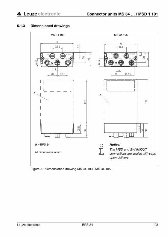
5.1.3 Dimensioned drawings
Figure 5.1:Dimensioned drawing MS 34 103 / MS 34 105
MS 34 105MS 34 103
A = BPS 34
All dimensions in mm
Notice!The MSD and SW IN/OUT connections are sealed with caps upon delivery.
Connector units MS 34 … / MSD 1 101 Leuze electronic
24 BPS 34 Leuze electronic
5.1.4 Electrical connection
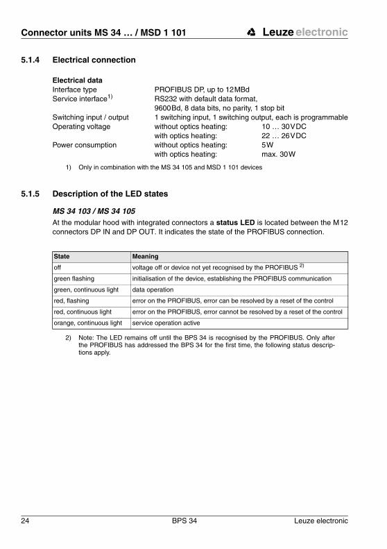
5.1.5 Description of the LED states
MS 34 103 / MS 34 105At the modular hood with integrated connectors a status LED is located between the M 12 connectors DP IN and DP OUT. It indicates the state of the PROFIBUS connection.
2) Note: The LED remains off until the BPS 34 is recognised by the PROFIBUS. Only after the PROFIBUS has addressed the BPS 34 for the first time, the following status descrip-tions apply.
Electrical dataInterface type PROFIBUS DP, up to 12 MBdService interface1)
1) Only in combination with the MS 34 105 and MSD 1 101 devices
RS232 with default data format, 9600 Bd, 8 data bits, no parity, 1 stop bit
Switching input / output 1 switching input, 1 switching output, each is programmableOperating voltage without optics heating: 10 … 30 V DC
with optics heating: 22 … 26 V DCPower consumption without optics heating: 5 W
with optics heating: max. 30 W
State Meaning
off voltage off or device not yet recognised by the PROFIBUS 2)
green flashing initialisation of the device, establishing the PROFIBUS communication
green, continuous light data operation
red, flashing error on the PROFIBUS, error can be resolved by a reset of the control
red, continuous light error on the PROFIBUS, error cannot be resolved by a reset of the control
orange, continuous light service operation active
Leuze electronic Connector units MS 34 … / MSD 1 101
Leuze electronic BPS 34 25
TN
T 3
5/7-
24V
5.2 Modular Service Display MSD 1 101
5.2.1 General information
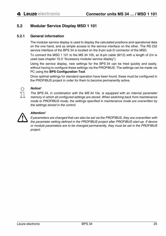
The modular service display is used to display the calculated positions and operational data on the one hand, and as simple access to the service interface on the other. The RS 232 service interface of the BPS 34 is located on the 9-pin sub-D connector of the MSD.
To connect the MSD 1 101 to the MS 34 105, an 8-pin cable (M 12) with a length of 2 m is used (see chapter 10.3 "Accessory modular service display").
Using the service display, new settings for the BPS 34 can be tried quickly and easily, without having to configure these settings via the PROFIBUS. The settings can be made via PC using the BPS Configuration Tool.
Once optimal settings for standard operation have been found, these must be configured in the PROFIBUS project in order for them to become permanently active.
Notice!The BPS 34, in combination with the MS 34 10x, is equipped with an internal parameter memory in which all configured settings are stored. When switching back from maintenance mode to PROFIBUS mode, the settings specified in maintenance mode are overwritten by the settings stored in the control.
Attention!If parameters are changed that can also be set via the PROFIBUS, they are overwritten with the parameter setting defined in the PROFIBUS project after PROFIBUS start-up. If device or module parameters are to be changed permanently, they must be set in the PROFIBUS project.
Connector units MS 34 … / MSD 1 101 Leuze electronic
26 BPS 34 Leuze electronic
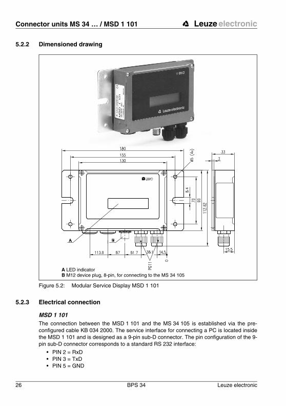
5.2.2 Dimensioned drawing
Figure 5.2: Modular Service Display MSD 1 101
5.2.3 Electrical connection
MSD 1 101The connection between the MSD 1 101 and the MS 34 105 is established via the pre-configured cable KB 034 2000. The service interface for connecting a PC is located inside the MSD 1 101 and is designed as a 9-pin sub-D connector. The pin configuration of the 9-pin sub-D connector corresponds to a standard RS 232 interface:
• PIN 2 = RxD• PIN 3 = TxD• PIN 5 = GND
A LED indicatorB M12 device plug, 8-pin, for connecting to the MS 34 105
Leuze electronic Barcode tape
Leuze electronic BPS 34 27
TN
T 3
5/7-
24V
6 Barcode tape
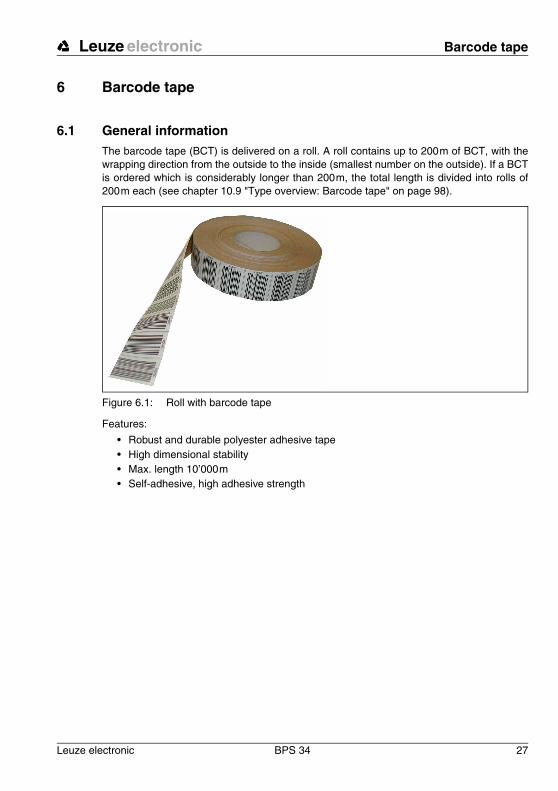
6.1 General informationThe barcode tape (BCT) is delivered on a roll. A roll contains up to 200 m of BCT, with the wrapping direction from the outside to the inside (smallest number on the outside). If a BCT is ordered which is considerably longer than 200 m, the total length is divided into rolls of 200 m each (see chapter 10.9 "Type overview: Barcode tape" on page 98).
Figure 6.1: Roll with barcode tape
Features:
• Robust and durable polyester adhesive tape• High dimensional stability• Max. length 10’000 m• Self-adhesive, high adhesive strength
Barcode tape Leuze electronic
28 BPS 34 Leuze electronic
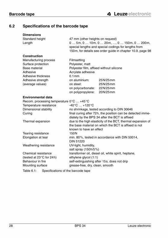
6.2 Specifications of the barcode tape
Table 6.1: Specifications of the barcode tape
DimensionsStandard height 47 mm (other heights on request)Length 0 … 5 m, 0 … 10 m, 0 … 20 m, …, 0 … 150 m, 0 … 200 m,
special lengths and special codings for lengths from 150 m, for details see order guide in chapter 10.9, page 98
ConstructionManufacturing process FilmsettingSurface protection Polyester, mattBase material Polyester film, affixed without siliconeAdhesive Acrylate adhesiveAdhesive thickness 0.1 mmAdhesive strength (average values)
on aluminium: 25 N/25 mm on steel: 25 N/25 mm on polycarbonate: 22 N/25 mm on polypropylene: 20 N/25 mm
Environmental dataRecom. processing temperature 0 °C … +45 °CTemperature resistance -40 °C … +120 °CDimensional stability no shrinkage, tested according to DIN 30646Curing final curing after 72 h, the position can be detected imme-
diately by the BPS 34 after the BCT is affixedThermal expansion due to the high elasticity of the BCT, thermal expansion of
the base material on which the BCT is affixed is not known to have an effect
Tearing resistance 150 NElongation at tear min. 80 %, tested in accordance with DIN 50014,
DIN 51220Weathering resistance UV-light, humidity,
salt spray (150 h/5 %)Chemical resistance (tested at 23 °C for 24 h)
transformer oil, diesel oil, white spirit, heptane, ethylene glycol (1:1)
Behaviour in fire self-extinguishing after 15 s, does not dripMounting surface grease-free, dry, clean, smooth
Leuze electronic Barcode tape
Leuze electronic BPS 34 29
TN
T 3
5/7-
24V
6.3 Mounting the barcode tapeTo prevent deposits of dirt from forming, it is recommended that the BCT be affixed verti-cally, possibly with a roof-like cover. If the application does not permit this, permanent cleaning of the BCT by on-board cleaning devices such as brushes or sponges is not permitted in any case. Permanent on-board cleaning devices polish the BCT and give it a glossy finish. The read quality deteriorates as a result.
Notice!When mounting the BCT, it must be ensured that neither strong sources of extraneous light nor reflections of the base on which the BCT is affixed occur in the area of the scanning beam.
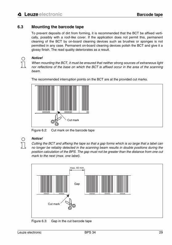
The recommended interruption points on the BCT are at the provided cut marks.
Figure 6.2: Cut mark on the barcode tape
Notice!Cutting the BCT and affixing the tape so that a gap forms which is so large that a label can no longer be reliably detected in the scanning beam results in double positions during the position calculation of the BPS. The gap must not be greater than the distance from one cut mark to the next (max. one label).
Figure 6.3: Gap in the cut barcode tape
000028 000032 00
Cut mark
000020 000024 000028 000032 000036
max. 40 mm
Cut mark
Gap
Barcode tape Leuze electronic
30 BPS 34 Leuze electronic
Procedure:
• Examine the mounting surface. It must be flat, without warping, free of grease and dust, and dry.
• Define a reference edge (e.g. metal edge of the busbar)• Remove the backing and affix the BCT along the reference edge tension free.
Secure the BCT to the mounting surface by pressing down with the palm of your hand. When affixing, make certain that the BCT is free of folds and creases and that no air pockets form.
• Never pull the BCT. Because this is a plastic tape, forceful pulling may stretch it. This results in a distortion of the measurement units on the tape. While the BPS 34 can still perform the position calculation, the accuracy in this case is no longer ensured. If the values are taught using a teach-in process, distortions are irrelevant.
• Expansion joints with widths up to several millimetres can simply be covered with the barcode tape. The tape must not be interrupted at this location.
• Protruding screw heads can simply be taped over. Cut out the bar code which covers the screw head at the cut marks.
• If the application dictates the necessity of a gap, the tape is to be affixed over this gap and the affected cut marks cut out. If the gap is small enough that the scanning beam can detect the label to the left or to the right of the gap, measurement values are delivered without interruption. If the scanning beam cannot completely scan any label, the BPS 34 returns the value 0. As soon as the BPS 34 can again scan a complete label, it calculates the next position value.
• The maximum gap between two barcode positions without affecting the measurement value is 40 mm.
Notice!If the barcode tape was damaged, e.g. by falling parts, a repair kit can be downloaded from the Internet (www.leuze.de -> Under the heading Download -> Logistics -> Optical barcode positioning -> Repair Kit for Barcode Tape).
Notice!You can also view a video which illustrates how to affix the barcode tape on the Internet at www.leuze.de -> Download -> Logistics -> Optical barcode positioning -> Videos -> How to mount BPS 34/37.
Attention!Barcode tapes with different value ranges may not directly follow one another. If the value ranges are different, the gap between the two BCTs must be greater than the detection range of the scanning beam or control barcodes must be used (for further information see chapter 6.4 on page 32).
Notice!When working with the BCT in cold warehouses, it should be ensured that the BCT be af-fixed before the warehouse is cooled. However, if it should be necessary to work with the BCT at temperatures outside of the specified processing temperature, please make certain that the bonding surface as well as the BCT are at the processing temperature.

Leuze electronic Barcode tape
Leuze electronic BPS 34 31
TN
T 3
5/7-
24V
Notice!When working with BCT in curves, the BCT should only be partially cut at the cut mark and affixed along the curve like a fan; it must also be ensured that the BCT is affixed without ten-sion (see figure 6.3).
Figure 6.4: Partial cutting of the barcode tape in curves
007000 007004
007008
007012
Barcode tape Leuze electronic
32 BPS 34 Leuze electronic
6.4 Control barcodeWith the aid of control barcodes, which are simply affixed over the barcode tape at the necessary locations, functions can be activated and deactivated in the BPS 34.
Notice!The control of functions using control barcodes is a new feature of the BPS 34. The imple-mentation of additional control options via control barcodes is in preparation.
Structure of the control barcodeThe control barcodes utilise code type Code128 with character set B; the position barcodes, on the other hand, utilise Code128 with character set C. Code 128 with character set B enables the display of all letters and numbers in the ASCII character set.
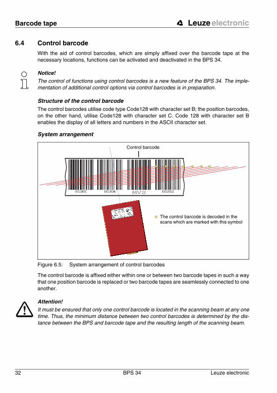
System arrangement
Figure 6.5: System arrangement of control barcodes
The control barcode is affixed either within one or between two barcode tapes in such a way that one position barcode is replaced or two barcode tapes are seamlessly connected to one another.
Attention!It must be ensured that only one control barcode is located in the scanning beam at any one time. Thus, the minimum distance between two control barcodes is determined by the dis-tance between the BPS and barcode tape and the resulting length of the scanning beam.
The control barcode is decoded in the scans which are marked with this symbol
Control barcode

Leuze electronic Barcode tape
Leuze electronic BPS 34 33
TN
T 3
5/7-
24V
For error-free function, when using control barcodes it must absolutely be ensured that the distance between the BPS and barcode tape is selected large enough. The scanning beam of the BPS should cover three or more barcodes; this is ensured at a distance which lies in the working range of the reading field curve.
The control barcodes are simply affixed over the existing tape. When affixing the control barcodes, make certain to cover entire barcodes to ensure that a barcode spacing of 4 cm is maintained.
Figure 6.6: Correct positioning of the control barcode
6.4.1 Controllable functions
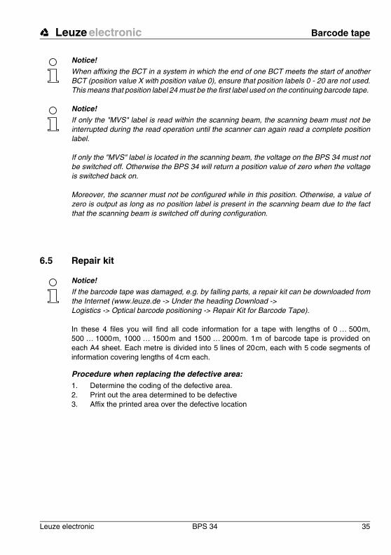
Measurement value switching between 2 barcode tapes with different value rangesThe "MVS" control barcode is used to switch between two barcode tapes. The end of one tape and the start of the next can end and begin, respectively, with completely different posi-tion barcodes. If the centre of the BPS 34 reaches the transition point of the control barcode, the device switches to the second tape, provided the next position label is in its scanning beam. As a result, the output position can always be uniquely associated with one tape.
Control barcode cor-rectly affixed on the barcode tape
Control barcode in-correctly affixed on the barcode tape
Barcode tape Leuze electronic
34 BPS 34 Leuze electronic
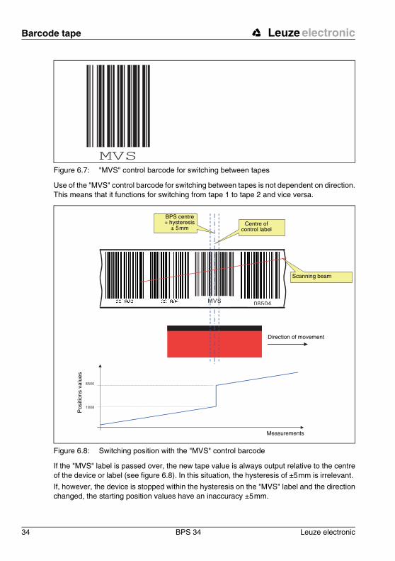
Figure 6.7: "MVS" control barcode for switching between tapes
Use of the "MVS" control barcode for switching between tapes is not dependent on direction. This means that it functions for switching from tape 1 to tape 2 and vice versa.
Figure 6.8: Switching position with the "MVS" control barcode
If the "MVS" label is passed over, the new tape value is always output relative to the centre of the device or label (see figure 6.8). In this situation, the hysteresis of ±5 mm is irrelevant.
If, however, the device is stopped within the hysteresis on the "MVS" label and the direction changed, the starting position values have an inaccuracy ±5 mm.
SM1MVS 08504
8500
1808
BPS centre + hysteresis
± 5 mmCentre of
control label
Scanning beam
Direction of movement
Measurements
Pos
ition
s va
lues
Leuze electronic Barcode tape
Leuze electronic BPS 34 35
TN
T 3
5/7-
24V
Notice!When affixing the BCT in a system in which the end of one BCT meets the start of another BCT (position value X with position value 0), ensure that position labels 0 - 20 are not used. This means that position label 24 must be the first label used on the continuing barcode tape.
Notice!If only the "MVS" label is read within the scanning beam, the scanning beam must not be interrupted during the read operation until the scanner can again read a complete position label.
If only the "MVS" label is located in the scanning beam, the voltage on the BPS 34 must not be switched off. Otherwise the BPS 34 will return a position value of zero when the voltage is switched back on.
Moreover, the scanner must not be configured while in this position. Otherwise, a value of zero is output as long as no position label is present in the scanning beam due to the fact that the scanning beam is switched off during configuration.
6.5 Repair kit
Notice!If the barcode tape was damaged, e.g. by falling parts, a repair kit can be downloaded from the Internet (www.leuze.de -> Under the heading Download -> Logistics -> Optical barcode positioning -> Repair Kit for Barcode Tape).
In these 4 files you will find all code information for a tape with lengths of 0 … 500 m, 500 … 1000 m, 1000 … 1500 m and 1500 … 2000 m. 1 m of barcode tape is provided on each A4 sheet. Each metre is divided into 5 lines of 20 cm, each with 5 code segments of information covering lengths of 4 cm each.
Procedure when replacing the defective area:1. Determine the coding of the defective area.2. Print out the area determined to be defective3. Affix the printed area over the defective location

Barcode tape Leuze electronic
36 BPS 34 Leuze electronic
Important note for printing: 1. Select only those pages that are actually required. 2. Change the printer settings so that the code is not distorted.
Suggestion for printer settings, see figure 6.9. 3. Verify the printing result by measuring the distance between two codes (see
figure 6.10). 4. Cut the code strips and concatenate them. It is important that the code content
always increases or decreases in blocks of 4 cm.
Figure 6.9: Printer settings for BCT repair kit
Figure 6.10: Checking the print results of the BCT repair kit
000020 000024 000028 000032 000036
40 mm

Leuze electronic Mounting
Leuze electronic BPS 34 37
TN
T 3
5/7-
24V
7 Mounting
7.1 Mounting the BPS 34There are two different types of mounting arrangements for the BPS 34:
• Using 4 M4x6 screws on the rear of the device.• Using the BT 56 mounting device on the fastening grooves.
Figure 7.1: BPS 34 mounting options
BT 56 mounting deviceThe BT 56 mounting device is available for mounting the BPS 34 using the fastening grooves. It is designed for rod installation (Ø 16 mm to 20 mm). For ordering instructions, please refer to chapter 10.6 on page 94.
Laser-beam beam hole
4 fastening threads M 4 on the rear of the device
15-pin sub-D con-nector on the under-side of the unit
Dovetail fastening grooves
Mounting Leuze electronic
38 BPS 34 Leuze electronic
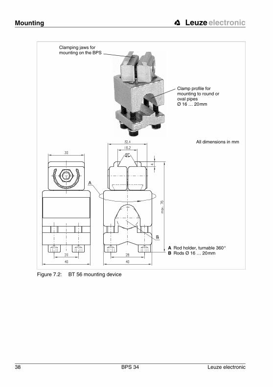
Figure 7.2: BT 56 mounting device
Clamping jaws for mounting on the BPS
Clamp profile for mounting to round or oval pipes Ø 16 … 20 mm
A Rod holder, turnable 360 °B Rods Ø 16 … 20 mm
All dimensions in mm
Leuze electronic Mounting
Leuze electronic BPS 34 39
TN
T 3
5/7-
24V
Mounting example BPS 34
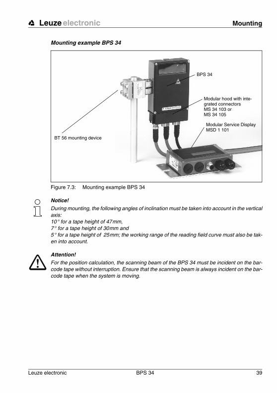
Figure 7.3: Mounting example BPS 34
Notice!During mounting, the following angles of inclination must be taken into account in the vertical axis: 10 ° for a tape height of 47 mm, 7 ° for a tape height of 30 mm and 5 ° for a tape height of 25 mm; the working range of the reading field curve must also be tak-en into account.
Attention!For the position calculation, the scanning beam of the BPS 34 must be incident on the bar-code tape without interruption. Ensure that the scanning beam is always incident on the bar-code tape when the system is moving.
BPS 34
BT 56 mounting device
Modular hood with inte-grated connectorsMS 34 103 orMS 34 105
Modular Service DisplayMSD 1 101
Mounting Leuze electronic
40 BPS 34 Leuze electronic
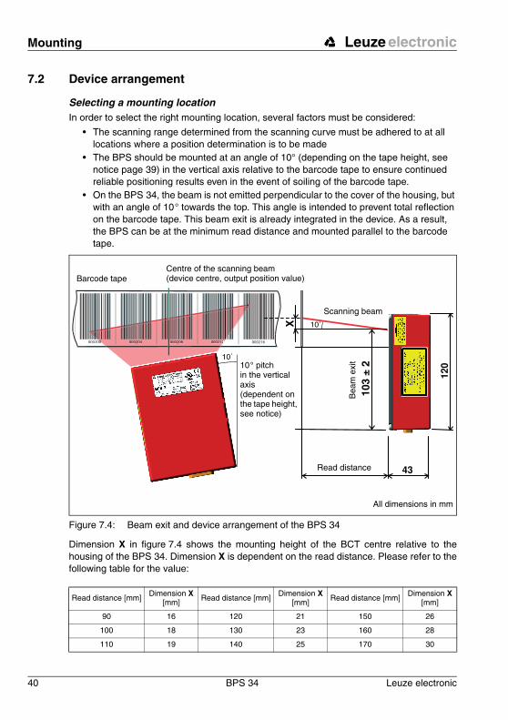
7.2 Device arrangement
Selecting a mounting locationIn order to select the right mounting location, several factors must be considered:
• The scanning range determined from the scanning curve must be adhered to at all locations where a position determination is to be made
• The BPS should be mounted at an angle of 10° (depending on the tape height, see notice page 39) in the vertical axis relative to the barcode tape to ensure continued reliable positioning results even in the event of soiling of the barcode tape.
• On the BPS 34, the beam is not emitted perpendicular to the cover of the housing, but with an angle of 10 ° towards the top. This angle is intended to prevent total reflection on the barcode tape. This beam exit is already integrated in the device. As a result, the BPS can be at the minimum read distance and mounted parallel to the barcode tape.
Figure 7.4: Beam exit and device arrangement of the BPS 34
Dimension X in figure 7.4 shows the mounting height of the BCT centre relative to the housing of the BPS 34. Dimension X is dependent on the read distance. Please refer to the following table for the value:
Read distance [mm]Dimension X
[mm] Read distance [mm]Dimension X
[mm] Read distance [mm]Dimension X
[mm]
90 16 120 21 150 26
100 18 130 23 160 28
110 19 140 25 170 30
000200 2 0002160 000204 000208 0002122
10˚10
3 ±
2
X 10˚
Read distance
Bea
m e
xit
All dimensions in mm
Barcode tapeCentre of the scanning beam(device centre, output position value)
Scanning beam
10 ° pitch in the vertical axis (dependent on the tape height, see notice)
Leuze electronic Mounting
Leuze electronic BPS 34 41
TN
T 3
5/7-
24V
Notice!The best functionality is obtained when:
• the BPS is guided parallel to the tape.• the permitted working range is not exited.
Mounting location
! When selecting a mounting location, pay attention to
• maintaining the required environmental conditions (humidity, temperature), • possible soiling of the reading window due to liquids, abrasion by boxes, or packaging
material residues.
Mounting outdoors/devices with integrated heatingWhen mounting outdoors or for devices with integrated heating, also observe the following points:
• mount the BPS 34 in a way which provides maximum thermal isolation, e.g. using rubber-bonded metal.
• mount in such a way that the device is protected from relative wind; mount additional shields if necessary.
Notice!When installing the BPS 34 in a protective housing, it must be ensured that the scanning beam can exit the protective housing without obstruction.
7.3 Mounting the barcode tapeThe BPS 34 and barcode tape combination is mounted in such a way that the scanning beam is unobstructed and is incident on the barcode tape as described in figure 7.4 on page 40.
Notice!For further information on mounting the barcode tape, please refer to chapter 6.3 on page 29.
Device parameters and interfaces Leuze electronic
42 BPS 34 Leuze electronic
8 Device parameters and interfaces
8.1 PROFIBUS
8.1.1 General information
The BPS 34 with MS 34 103/MS 34 105 is designed as a PROFIBUS device (PROFIBUS DP-V0 acc. to IEC 61784-1) with a baud rate of 12 MBd. The functionality of the device is defined via parameter sets which are clustered in modules. These modules are contained in a GSE file. The GSE file can be downloaded from the Leuze Homepage at www.leuze.de -> under the heading Download -> Logistics -> Optical barcode positioning. By using a user-specific project tool, such as, e.g., Simatic Manager for the Siemens programmable logic control, the required modules are integrated into a project during commissioning and its settings and parameters are adjusted accordingly. These modules are provided by the GSE file.
All input and output modules described in this documentation are described from the controller's perspective:
• Input data arrives at the controller• Output data are sent out by the controller.
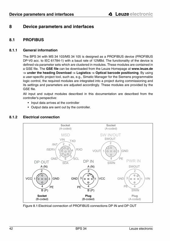
8.1.2 Electrical connection
Figure 8.1:Electrical connection of PROFIBUS connections DP IN and DP OUT
Socket(A-coded)
Socket(A-coded)
Socket(B-coded)
Plug(B-coded)
Plug(A-coded)
DP IN
GND 3
2
1
4PE
A (N)
B (P)
VCC
DP OUT
VCC 1
2
3
4
A (N)
B (P)
GND
PE
PWR IN
SWIN
SWOUT
3
2
1
4
GND VIN
PE
SW IN/OUT
1
2
3
4
VOUT
PE
SWIN
SWOUT
GND1
2 3
4
MSD
56
7
/SERV
VINTXD
RXD
SCL
SDA
GND
/INT

Leuze electronic Device parameters and interfaces
Leuze electronic BPS 34 43
TN
T 3
5/7-
24V
DP IN - PROFIBUS DP incoming
Figure 8.2: Pin assignment DP IN
DP OUT - PROFIBUS DP outgoing
Figure 8.3: Pin assignment DP IN
Attention!Protection class IP 65 is achieved only if the connectors and caps are screwed into place!
DP IN (5-pin plug, B-coded)
Pin Name Remark
1 VCC 5 V DC for bus termination
2 A (N) Receive/transmit data A-line (N)
3 GND Functional earth for bus termination
4 B (P) Receive/transmit data B-line (P)
5 PE Functional earth
Thread PE Functional earth (housing)
DPOUT (5-pin socket, B-coded)
Pin Name Remark
1 VCC 5 V DC for bus termination
2 A (N) Receive/transmit data A-line (N)
3 GND Functional earth for bus termination
4 B (P) Receive/transmit data B-line (P)
5 PE Functional earth
Thread PE Functional earth (housing)
DP IN
GND 3
2
1
4PE
A (N)
B (P)
VCC
M 12 plug(B-coded)
DP OUT
VCC 1
2
3
4
A (N)
B (P)
GND
PE
M 12 socket(B-coded)
Device parameters and interfaces Leuze electronic
44 BPS 34 Leuze electronic
Notice!For connecting DP IN and DP OUT, we recommend our ready-made PROFIBUS cables. For further information, see chapter 10.8 on page 96.
The BPS 34 can be used in combination with an MS 34 103/MS 34 105 to branch out the PROFIBUS network. The continuing network is connected via DP OUT.
If the PROFIBUS is not connected to another subscriber via the MS 34 10x, the DP OUT connection must be fitted with a TS 02-4-SA terminator plug for the purpose of bus termina-tion. For further information, see also chapter 10.4 on page 94.
Attention!Never open the device yourself, as this may compromise protection class IP 65.
Before connecting the device, be sure that the supply voltage agrees with the value printed on the name plate.
Connection of the device and cleaning must only be carried out by a qualified electrician.
The power supply unit for the generation of the supply voltage for the BPS 34 and the re-spective connection units must have a secure electrical insulation through double insulation and safety transformers according to EN 60742 (corresponds to IEC 60742).
Be sure that the earthing conductor is connected correctly. Error-free operation is only guar-anteed if the device is properly earthed.
If faults cannot be corrected, the device should be removed from operation and protected against possible use.
To then further isolate the error, proceed as described in chapter 9 on page 92.
Leuze electronic Device parameters and interfaces
Leuze electronic BPS 34 45
TN
T 3
5/7-
24V
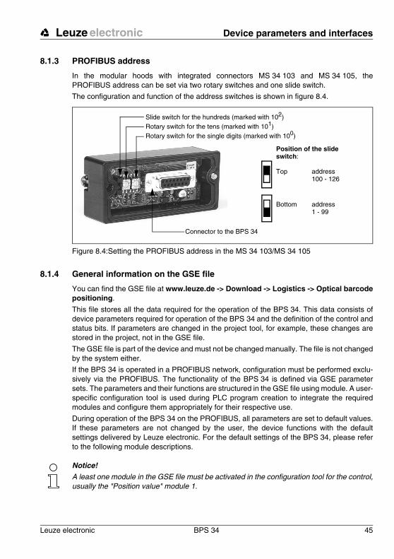
8.1.3 PROFIBUS address
In the modular hoods with integrated connectors MS 34 103 and MS 34 105, the PROFIBUS address can be set via two rotary switches and one slide switch.
The configuration and function of the address switches is shown in figure 8.4.
Figure 8.4:Setting the PROFIBUS address in the MS 34 103/MS 34 105
8.1.4 General information on the GSE file
You can find the GSE file at www.leuze.de -> Download -> Logistics -> Optical barcode positioning.
This file stores all the data required for the operation of the BPS 34. This data consists of device parameters required for operation of the BPS 34 and the definition of the control and status bits. If parameters are changed in the project tool, for example, these changes are stored in the project, not in the GSE file.
The GSE file is part of the device and must not be changed manually. The file is not changed by the system either.
If the BPS 34 is operated in a PROFIBUS network, configuration must be performed exclu-sively via the PROFIBUS. The functionality of the BPS 34 is defined via GSE parameter sets. The parameters and their functions are structured in the GSE file using module. A user-specific configuration tool is used during PLC program creation to integrate the required modules and configure them appropriately for their respective use.
During operation of the BPS 34 on the PROFIBUS, all parameters are set to default values. If these parameters are not changed by the user, the device functions with the default settings delivered by Leuze electronic. For the default settings of the BPS 34, please refer to the following module descriptions.
Notice!A least one module in the GSE file must be activated in the configuration tool for the control, usually the "Position value" module 1.
Slide switch for the hundreds (marked with 102)Rotary switch for the tens (marked with 101)Rotary switch for the single digits (marked with 100)
Connector to the BPS 34
Position of the slide switch:
Top address100 - 126
Bottom address1 - 99
Device parameters and interfaces Leuze electronic
46 BPS 34 Leuze electronic
Notice!Some controls make available a so-called "universal module". This module must not be ac-tivated for the laser.
Attention! The BPS 34 does not permanently store parameters changed via the PROFIBUS. Following Power off/on, the currently configured parameters are downloaded from the PROFIBUS manager. If no PROFIBUS manager is available following Power OFF/ON, the BPS 34 ac-tivates its stored default settings.
8.1.5 Structure of the GSE modules
In the current version, a total of 27 modules are available for use. The modules may be included into the project according to requirements and application.
The modules fall into the following categories:
• Parameter module for the configuration of the BPS 34.• Status or control modules that influence the input/output data.• Modules that may include both parameters and control or status information.
Notice!All input and output modules described in this documentation are described from the controller's perspective. Described inputs (I) are inputs in the control. Described outputs (O) are outputs in the control. Described parameters (P) are parameters of the GSE file in the control.
Notice!At least one module must be activated to permit operation of the device at the PROFIBUS DP.
Notice!Under some circumstances, not all 27 modules can be activated simultaneously in the con-figuration tool. Otherwise, the available memory for a subscriber may be exceeded. The maximum available memory for a device is control dependent.
Leuze electronic Device parameters and interfaces
Leuze electronic BPS 34 47
TN
T 3
5/7-
24V
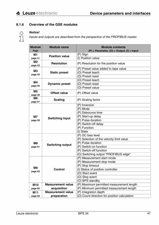
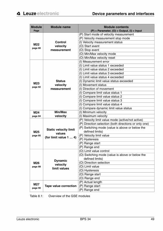
8.1.6 Overview of the GSE modules
Notice!Inputs and outputs are described from the perspective of the PROFIBUS master.
ModulePage
Module name Module contents(P) = Parameter, (O) = Output, (I) = Input
M1page 51
Position value(P) Sign(I) Position value
M2page 52
Resolution (P) Resolution for the position value
M3page 53
Static preset(P) Preset value added to tape value(O) Preset teach(O) Preset reset
M4page 55
Dynamic preset(O) Preset teach(O) Preset reset(O) Preset value
M5page 56
Offset value (P) Offset value
M6page 57
Scaling (P) Scaling factor
M7page 59
Switching input
(P) Inversion(P) Mode(P) Debounce time(P) Start-up delay(P) Pulse duration(P) Switch-off delay(P) Function(I) State
M8page 61
Switching output
(P) DC bias level(P) Selection of the velocity limit value(P) Pulse duration(P) Switch-on function(P) Switch-off function(O) Switching output "PROFIBUS edge"
M9page 63
Control
(P) Measurement start mode(P) Measurement stop mode(P) Stop timeout(I) Status of position controller(O) Start event(O) Stop event(O) BPS standby
M10page 65
Measurement value acquisition
(P) Maximum permitted measurement length(P) Minimum permitted measurement length
M11page 66
Measurement value preparation
(P) Integration depth(O) Count direction for position calculation
Device parameters and interfaces Leuze electronic
48 BPS 34 Leuze electronic
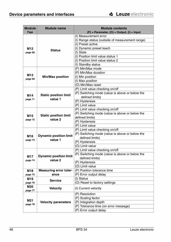
M12page 68
Status
(I) Measurement error(I) Range status (outside of measurement range)(I) Preset active(I) Dynamic preset teach(I) State(I) Position limit value status 1(I) Position limit value status 2(I) Standby status
M13page 69
Min/Max position
(P) Min/Max mode(P) Min/Max duration(I) Min position(I) Max position(O) Min/Max reset
M14page 71
Static position limit value 1
(P) Limit value checking on/off(P) Switching mode (value is above or below the
defined limits)(P) Hysteresis(P) Limit value
M15page 72
Static position limit value 2
(P) Limit value checking on/off(P) Switching mode (value is above or below the defined limits)(P) Hysteresis(P) Limit value
M16page 73
Dynamic position limit value 1
(P) Limit value checking on/off(P) Switching mode (value is above or below the
defined limits)(P) Hysteresis(O) Limit value
M17page 74
Dynamic position limit value 2
(P) Limit value checking on/off(P) Switching mode (value is above or below the
defined limits)(P) Hysteresis(O) Limit value
M18page 75
Measuring error toler-ance
(P) Position tolerance time(P) Error output delay
M19page 76
Service(I) Status(O) Reset to factory settings
M20page 77
Velocity (I) Current velocity
M21page 78
Velocity parameters
(P) Resolution(P) Scaling factor(P) Integration depth(P) Tolerance time (on error message)(P) Error output delay
ModulePage
Module name Module contents(P) = Parameter, (O) = Output, (I) = Input
Leuze electronic Device parameters and interfaces
Leuze electronic BPS 34 49
TN
T 3
5/7-
24V
Table 8.1: Overview of the GSE modules
M22page 80
Control velocity
measurement
(P) Start mode of velocity measurement(P) Velocity measurement stop mode(I) Velocity measurement status(O) Start event(O) Stop event(O) Min/Max velocity mode(O) Min/Max velocity reset
M23page 82
Statusvelocity
measurement
(I) Measurement error(I) Limit value status 1 exceeded(I) Limit value status 2 exceeded(I) Limit value status 3 exceeded(I) Limit value status 4 exceeded(I) Dynamic limit value status exceeded(I) Movement status(I) Direction of movement(I) Compare limit value status 1(I) Compare limit value status 2(I) Compare limit value status 3(I) Compare limit value status 4(I) Compare dynamic limit value status
M24page 84
Min/Max velocity
(I) Minimum velocity(I) Maximum velocity
M25page 85
Static velocity limit values
(for limit value 1 … 4)
(P) Velocity limit value mode (active/not active)(P) Direction selection (both directions or only one)(P) Switching mode (value is above or below the
defined limits)(P) Velocity limit value(P) Hysteresis(P) Range start(P) Range end
M26page 88
Dynamicvelocity
limit values
(O) Limit value control(O) Switching mode (value is above or below the
defined limits)(O) Direction selection(O) Limit value(O) Hysteresis(O) Range start(O) Range end
M27page 90
Tape value correction(P) Actual length(P) Range start(P) Range end
ModulePage
Module name Module contents(P) = Parameter, (O) = Output, (I) = Input
Device parameters and interfaces Leuze electronic
50 BPS 34 Leuze electronic
8.1.7 Detailed description of the modules
Notice!In the following detailed descriptions of the modules, you will find in the last column of the tables cross references (CR) to parameters and input/output data of other moduleswhich are directly related to the described parameter. These cross references must be ob-served during configuration.
The individual modules are numerically labelled from 1 … 27. The parameters and input/output data within a module are alphanumerically labelled from … .
Example:
The Static preset value in [mm] parameter in module 3 becomes active only when the preset teach occurs via module 12 , 7 or 3 .
a z
ac g b

Leuze electronic Device parameters and interfaces
Leuze electronic BPS 34 51
TN
T 3
5/7-
24V
8.1.7.1 Module 1: Position value
Description:With this module, the current position value is output.
Notice!The position value is the position value calculated from the tape value and the settings for resolution, preset and offset.
Parameter
Hex coding of module 1 "Position value"The value listed in the table shows the hex coding of the default settings.
Input data
Notice!A negative number is represented in the input data by a 1 in the most significant bit.
Output datanone
Parameter Description Rel. addr.
Data type
Value range Default Unit CR to module
SignOutput mode for sign. 0 unsign
80: Two's complement1: Sign + magnitude
0 – –
Parameter length: 1 byte
a
Inte
rnal
ad
dre
ss
of
mo
du
le 1
Sig
n
13 00
Input data Description Rel. addr.
Data type
Value range Default Unit CR to module
Position value
Output of the current position. 0 sign 32
-10’000’000 … +10’000’000(for a resolution in mm)
0 scaled –
Input data length: 4 byte
b
Device parameters and interfaces Leuze electronic
52 BPS 34 Leuze electronic
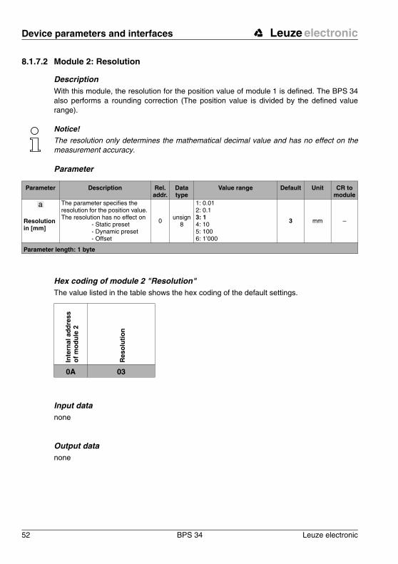
8.1.7.2 Module 2: Resolution
Description With this module, the resolution for the position value of module 1 is defined. The BPS 34 also performs a rounding correction (The position value is divided by the defined value range).
Notice!The resolution only determines the mathematical decimal value and has no effect on the measurement accuracy.
Parameter
Hex coding of module 2 "Resolution"The value listed in the table shows the hex coding of the default settings.
Input datanone
Output datanone
Parameter Description Rel. addr.
Data type
Value range Default Unit CR to module
Resolution in [mm]
The parameter specifies the resolution for the position value. The resolution has no effect on
- Static preset - Dynamic preset - Offset
0 unsign8
1: 0.012: 0.13: 14: 105: 1006: 1’000
3 mm –
Parameter length: 1 byte
a
Inte
rnal
ad
dre
ss
of
mo
du
le 2
Res
olu
tio
n
0A 03
Leuze electronic Device parameters and interfaces
Leuze electronic BPS 34 53
TN
T 3
5/7-
24V
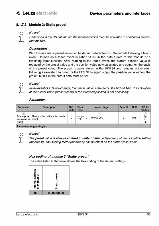
8.1.7.3 Module 3: Static preset
Notice!Underlined in the CR column are the modules which must be activated in addition to the cur-rent module.
DescriptionWith this module, a preset value can be defined which the BPS 34 outputs following a teach event. Defined as a teach event is either bit 0.0 in the output data of this module or a switching input function. After reading in the teach event, the current position value is replaced by the preset value and the position value now calculated and output on the basis of the preset value. The preset remains stored in the BPS 34 and remains active even following a new start. In order for the BPS 34 to again output the position value without the preset, bit 0.1 in the output data must be set.
Notice!In the event of a device change, the preset value is retained in the MS 34 10x. The activation of the preset value (preset teach) at the intended position is not necessary.
Parameter
Notice!The preset value is always entered in units of mm, independent of the resolution setting (module 2). The scaling factor (module 6) has no effect on the static preset value.
Hex coding of module 3 "Static preset"The value listed in the table shows the hex coding of the default settings.
Parameter Description Rel. addr.
Data type
Value range Default Unit CR to module
Static pre-set value in [mm]
New position value after teach event
0 unsign32
0 … 10’000’000 0 mm
12c7gor3b
Parameter length: 4 byte
a
Inte
rnal
ad
dre
ss
of
mo
du
le 3
Sta
tic
pre
set
06 00 00 00 00
Device parameters and interfaces Leuze electronic
54 BPS 34 Leuze electronic
Input datanone
Output data
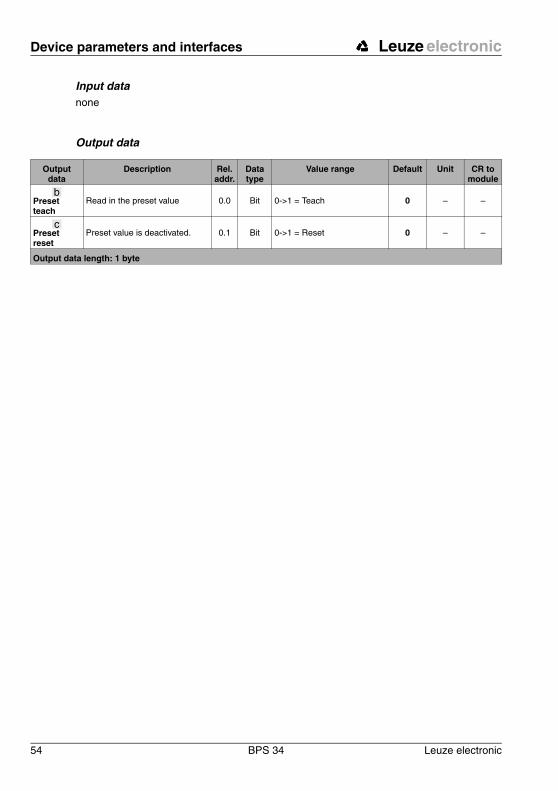
Output data
Description Rel. addr.
Data type
Value range Default Unit CR to module
Preset teach
Read in the preset value 0.0 Bit 0->1 = Teach 0 – –
Preset reset
Preset value is deactivated. 0.1 Bit 0->1 = Reset 0 – –
Output data length: 1 byte
b
c
Leuze electronic Device parameters and interfaces
Leuze electronic BPS 34 55
TN
T 3
5/7-
24V
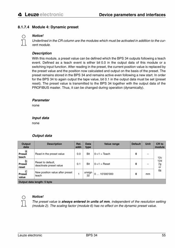
8.1.7.4 Module 4: Dynamic preset
Notice!Underlined in the CR column are the modules which must be activated in addition to the cur-rent module.
DescriptionWith this module, a preset value can be defined which the BPS 34 outputs following a teach event. Defined as a teach event is either bit 0.0 in the output data of this module or a switching input function. After reading in the preset, the current position value is replaced by the preset value and the position now calculated and output on the basis of the preset. The preset remains stored in the BPS 34 and remains active even following a new start. In order for the BPS 34 to again output the tape value, bit 0.1 in the output data must be set (preset reset). The preset value is transmitted to the BPS 34 together with the output data of the PROFIBUS master. Thus, it can be changed during operation (dynamically).
Parameternone
Input datanone
Output data
Notice!The preset value is always entered in units of mm, independent of the resolution setting (module 2). The scaling factor (module 6) has no effect on the dynamic preset value.
Output data
Description Rel. addr.
Data type
Value range Default Unit CR to module
Preset teach
Read in the preset value 0.0 Bit 0->1 = Teach 0 –12c12d7gor4a
Preset reset
Reset to default, deactivate preset value
0.1 Bit 0->1 = Reset 0 –
Preset value
New position value after preset teach
1 unsign32
0 … 10’000’000 0 mm
Output data length: 5 byte
a
b
c
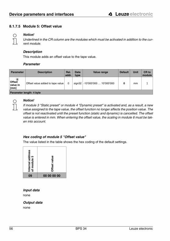
Device parameters and interfaces Leuze electronic
56 BPS 34 Leuze electronic
8.1.7.5 Module 5: Offset value
Notice!Underlined in the CR column are the modules which must be activated in addition to the cur-rent module.
DescriptionThis module adds an offset value to the tape value.
Parameter
Notice!If module 3 "Static preset" or module 4 "Dynamic preset" is activated and, as a result, a new value assigned to the tape value, the offset function no longer affects the position value. The offset is not reactivated until the preset function (static and dynamic) is cancelled. The offset value is entered in mm. When entering the offset value, the scaling in module 6 must be tak-en into account.
Hex coding of module 5 "Offset value"The value listed in the table shows the hex coding of the default settings.
Input datanone
Output datanone
Parameter Description Rel. addr.
Data type
Value range Default Unit CR to module
Offset value in [mm]
Offset value added to tape value 0 sign32 -10’000’000 … 10’000’000 0 mm 1
Parameter length: 4 byte
a
Inte
rnal
ad
dre
ss
of
mo
du
le 5
Off
set
valu
e
09 00 00 00 00
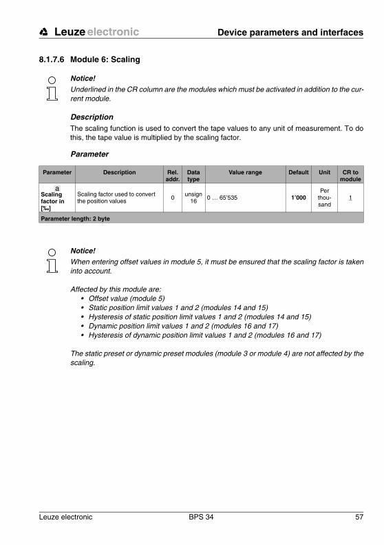
Leuze electronic Device parameters and interfaces
Leuze electronic BPS 34 57
TN
T 3
5/7-
24V
8.1.7.6 Module 6: Scaling
Notice!Underlined in the CR column are the modules which must be activated in addition to the cur-rent module.
DescriptionThe scaling function is used to convert the tape values to any unit of measurement. To do this, the tape value is multiplied by the scaling factor.
Parameter
Notice!When entering offset values in module 5, it must be ensured that the scaling factor is taken into account.
Affected by this module are:• Offset value (module 5)• Static position limit values 1 and 2 (modules 14 and 15)• Hysteresis of static position limit values 1 and 2 (modules 14 and 15)• Dynamic position limit values 1 and 2 (modules 16 and 17)• Hysteresis of dynamic position limit values 1 and 2 (modules 16 and 17)
The static preset or dynamic preset modules (module 3 or module 4) are not affected by the scaling.
Parameter Description Rel. addr.
Data type
Value range Default Unit CR to module
Scaling factor in [‰]
Scaling factor used to convert the position values 0 unsign
16 0 … 65’535 1’000Per
thou-sand
1
Parameter length: 2 byte
a
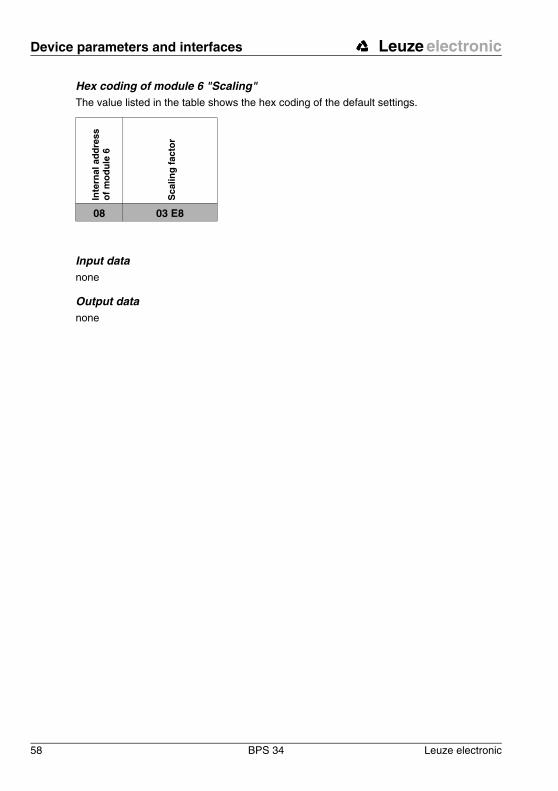
Device parameters and interfaces Leuze electronic
58 BPS 34 Leuze electronic
Hex coding of module 6 "Scaling"The value listed in the table shows the hex coding of the default settings.
Input datanone
Output datanone
Inte
rnal
ad
dre
ss
of
mo
du
le 6
Sca
ling
fac
tor
08 03 E8

Leuze electronic Device parameters and interfaces
Leuze electronic BPS 34 59
TN
T 3
5/7-
24V
8.1.7.7 Module 7: Switching input
Notice!Underlined in the CR column are the modules which must be activated in addition to the cur-rent module.
DescriptionThe module defines the mode of operation of the digital switching input.
Parameter
Parameter Description Rel. addr.
Data type
Value range Default Unit CR to module
Inversion
The parameter defines the logic of the pending signal. In case of an inversion, an external HIGH level is interpreted as an internal LOW level.
0 unsign8
0: No (active high)1: Yes (active low) 0 – –
ModeThis parameter controls the release of the switching input. 1 unsign
80: Off1: On 1 – –
Debounce time in [ms]
This parameter defines a debounce time which is imple-mented in software.
2unsign
8 0 … 255 5 ms –
Start-up delay in [ms]
The parameter influences the timing during switch-on
3 unsign16
0 … 65’535 0 ms –
Pulse dura-tion in [ms]
The parameter defines the mini-mum pulse duration of the input signal.
5 unsign16
0 … 65’535 0 ms –
a
b
c
d
e
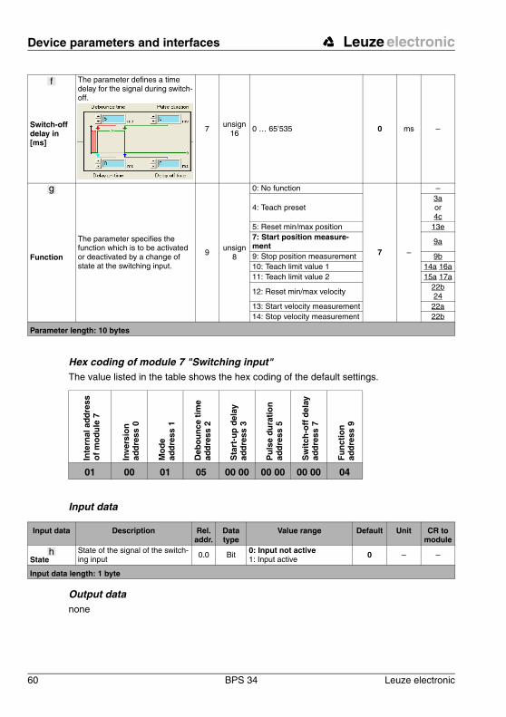
Device parameters and interfaces Leuze electronic
60 BPS 34 Leuze electronic
Hex coding of module 7 "Switching input"The value listed in the table shows the hex coding of the default settings.
Input data
Output datanone
Switch-off delay in [ms]
The parameter defines a time delay for the signal during switch-off.
7 unsign16
0 … 65’535 0 ms –
Function
The parameter specifies the function which is to be activated or deactivated by a change of state at the switching input.
9unsign
8
0: No function
7 –
–
4: Teach preset3a or 4c
5: Reset min/max position 13e7: Start position measure-ment 9a
9: Stop position measurement 9b10: Teach limit value 1 14a 16a11: Teach limit value 2 15a 17a
12: Reset min/max velocity22b 24
13: Start velocity measurement 22a14: Stop velocity measurement 22b
Parameter length: 10 bytes
f
g
Inte
rnal
ad
dre
ss
of
mo
du
le 7
Inve
rsio
n
add
ress
0
Mo
de
ad
dre
ss 1
Deb
ou
nce
tim
e ad
dre
ss 2
Sta
rt-u
p d
elay
ad
dre
ss 3
Pu
lse
du
rati
on
ad
dre
ss 5
Sw
itch
-off
del
ay
add
ress
7
Fu
nct
ion
ad
dre
ss 9
01 00 01 05 00 00 00 00 00 00 04
Input data Description Rel. addr.
Data type
Value range Default Unit CR to module
StateState of the signal of the switch-ing input
0.0 Bit 0: Input not active1: Input active
0 – –
Input data length: 1 byte
h

Leuze electronic Device parameters and interfaces
Leuze electronic BPS 34 61
TN
T 3
5/7-
24V
8.1.7.8 Module 8: Switching output
Notice!Underlined in the CR column are the modules which must be activated in addition to the cur-rent module.
DescriptionThe module defines the mode of operation of the digital switching output.
Parameter
Parameter Description Rel. addr.
Data type
Value range Default Unit CR to module
DC bias level
The parameter defines the DC bias level of the switching output. 0
unsign8
0: LOW (0 V)1: HIGH (+UB) 0 – –
Velocity limit value selection
Defines whether the switching out-put is controlled by static velocity limit value 1, static velocity limit value 2, static velocity limit value 3, static velocity limit value 4 or the dynamic velocity limit value
1.01.11.21.3
1.4
Bitsfor each 0: No 1: Yes
0000
0
–
25 for static
26 for dynamic
Pulse dura-tion in [ms]
The parameter defines the switch-on time period for the switching output. If the value is 0, the signal is static.
2 unsign16
0 … 1’300 400 ms –
Switch-on function [ON]
The parameter defines the events which set the switching output: - velocity valid- velocity not valid- position limit value 1 reached- position limit value 1 not reached- outside measurement range- inside measurement range- position limit value 2 reached- position limit value 2 not reached- erroneous measurement- successful measurement- PROFIBUS positive edge- PROFIBUS negative edge- velocity limit value reached- velocity limit value not reached
4.04.14.24.34.44.54.64.75.25.35.45.55.65.7
Bitsfor each 0: Not active 1: Active
00000000100000
–
2222
14 + 1614 + 16
1010
15 + 1715 + 171 + 91 + 9
882525
a
b
c
d
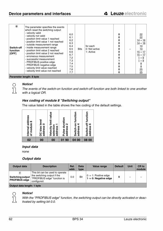
Device parameters and interfaces Leuze electronic
62 BPS 34 Leuze electronic
Notice!The events of the switch-on function and switch-off function are both linked to one another with a logical OR.
Hex coding of module 8 "Switching output"The value listed in the table shows the hex coding of the default settings.
Input datanone
Output data
Notice!With the "PROFIBUS edge" function, the switching output can be directly activated or deac-tivated by setting bit 0.0.
Switch-off function [OFF]
The parameter specifies the events which reset the switching output:- velocity valid- velocity not valid- position limit value 1 reached- position limit value 1 not reached- outside measurement range- inside measurement range- position limit value 2 reached- position limit value 2 not reached- erroneous measurement- successful measurement- PROFIBUS positive edge- PROFIBUS negative edge- velocity limit value reached- velocity limit value not reached
6.06.16.26.36.46.56.66.77.27.37.47.57.67.7
Bitsfor each 0: Not active 1: Active
00000000010000
–
2222
14 + 1614 + 16
1010
15 + 1715 + 171 + 91 + 9
88
2525
Parameter length: 8 byte
eIn
tern
al a
dd
ress
o
f m
od
ule
8
DC
bia
s le
vel
add
ress
0
Vel
oci
ty li
mit
val
ue
se
lect
ion
ad
dre
ss 1
Pu
lse
du
rati
on
ad
dre
ss 2
Sw
itch
-on
fu
nct
ion
ad
dre
ss 4
Sw
itch
-off
fu
nct
ion
ad
dre
ss 6
02 00 00 01 90 04 00 08 00
Output data Description Rel. addr.
Data type
Value range Default Unit CR to module
Switching output PROFIBUS edge
This bit can be used to operate the switching output if the "PROFIBUS edge" function is configured.
0.0 Bit 0 -> 1: Positive edge1 -> 0: Negative edge 0 – –
Output data length: 1 byte
f
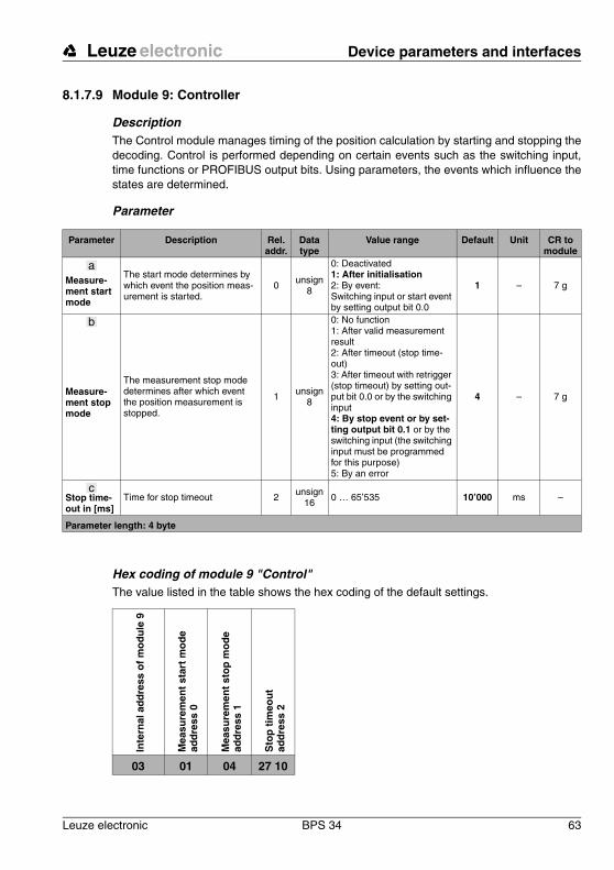
Leuze electronic Device parameters and interfaces
Leuze electronic BPS 34 63
TN
T 3
5/7-
24V
8.1.7.9 Module 9: Controller
DescriptionThe Control module manages timing of the position calculation by starting and stopping the decoding. Control is performed depending on certain events such as the switching input, time functions or PROFIBUS output bits. Using parameters, the events which influence the states are determined.
Parameter
Hex coding of module 9 "Control"The value listed in the table shows the hex coding of the default settings.
Parameter Description Rel. addr.
Data type
Value range Default Unit CR to module
Measure-ment start mode
The start mode determines by which event the position meas-urement is started.
0 unsign8
0: Deactivated1: After initialisation2: By event:Switching input or start event by setting output bit 0.0
1 – 7 g
Measure-ment stop mode
The measurement stop mode determines after which event the position measurement is stopped.
1 unsign8
0: No function1: After valid measurement result2: After timeout (stop time-out)3: After timeout with retrigger (stop timeout) by setting out-put bit 0.0 or by the switching input4: By stop event or by set-ting output bit 0.1 or by the switching input (the switching input must be programmed for this purpose)5: By an error
4 – 7 g
Stop time-out in [ms]
Time for stop timeout 2unsign
16 0 … 65’535 10’000 ms –
Parameter length: 4 byte
a
b
c
Inte
rnal
ad
dre
ss o
f m
od
ule
9
Mea
sure
men
t st
art
mo
de
add
ress
0
Mea
sure
men
t st
op
mo
de
add
ress
1
Sto
p t
imeo
ut
ad
dre
ss 2
03 01 04 27 10
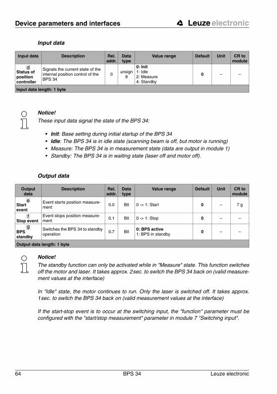
Device parameters and interfaces Leuze electronic
64 BPS 34 Leuze electronic
Input data
Notice!These input data signal the state of the BPS 34:
• Init: Base setting during initial startup of the BPS 34• Idle: The BPS 34 is in idle state (scanning beam is off, but motor is running)• Measure: The BPS 34 is in measurement state (data are output in module 1)• Standby: The BPS 34 is in waiting state (laser off and motor off).
Output data
Notice!The standby function can only be activated while in "Measure" state. This function switches off the motor and laser. It takes approx. 2 sec. to switch the BPS 34 back on (valid measure-ment values at the interface)
In "Idle" state, the motor continues to run. Only the laser is switched off. It takes approx. 1 sec. to switch the BPS 34 back on (valid measurement values at the interface)
If the start-stop event is to occur at the switching input, the "function" parameter must be configured with the "start/stop measurement" parameter in module 7 "Switching input".
Input data Description Rel. addr.
Data type
Value range Default Unit CR to module
Status of position controller
Signals the current state of the internal position control of the BPS 34
0 unsign8
0: Init1: Idle2: Measure4: Standby
0 – –
Input data length: 1 byte
d
Output data
Description Rel. addr.
Data type
Value range Default Unit CR to module
Start event
Event starts position measure-ment 0.0 Bit 0 -> 1: Start 0 – 7 g
Stop eventEvent stops position measure-ment 0.1 Bit 0 -> 1: Stop 0 – –
BPS standby
Switches the BPS 34 to standby operation
0.7 Bit 0: BPS active1: BPS in standby
0 – –
Output data length: 1 byte
e
f
g
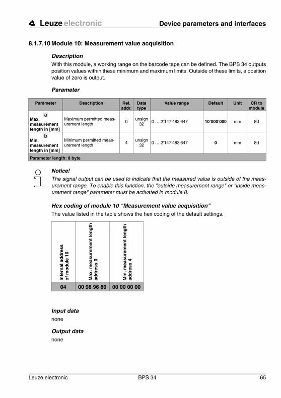
Leuze electronic Device parameters and interfaces
Leuze electronic BPS 34 65
TN
T 3
5/7-
24V
8.1.7.10 Module 10: Measurement value acquisition
Description With this module, a working range on the barcode tape can be defined. The BPS 34 outputs position values within these minimum and maximum limits. Outside of these limits, a position value of zero is output.
Parameter
Notice!The signal output can be used to indicate that the measured value is outside of the meas-urement range. To enable this function, the "outside measurement range" or "inside meas-urement range" parameter must be activated in module 8.
Hex coding of module 10 "Measurement value acquisition"The value listed in the table shows the hex coding of the default settings.
Input datanone
Output datanone
Parameter Description Rel. addr.
Data type
Value range Default Unit CR to module
Max. measurement length in [mm]
Maximum permitted meas-urement length 0 unsign
32 0 … 2’147’483’647 10’000’000 mm 8d
Min. measurement length in [mm]
Minimum permitted meas-urement length 4
unsign32 0 … 2’147’483’647 0 mm 8d
Parameter length: 8 byte
a
b
Inte
rnal
ad
dre
ss
of
mo
du
le 1
0
Max
. mea
sure
men
t le
ng
th
add
ress
0
Min
. mea
sure
men
t le
ng
th
add
ress
4
04 00 98 96 80 00 00 00 00

Device parameters and interfaces Leuze electronic
66 BPS 34 Leuze electronic
8.1.7.11 Module 11: Measurement value processing
DescriptionThe integration depth parameter is used to specify the number of raw position data which is used for integration in order to determine the position value.
In order to obtain positive or negative position values depending on the direction of move-ment of the BPS 34, the count direction can be selected as normal or inverted in the output data of this module.
In order to obtain more exact measurement data while in the static state or for very slow travel speeds, the integration depth can be increased here. If, however, a high integration depth is used for high speeds, the contouring error is increased. With respect to contouring error and exact measurement data, very good results have been obtained using 8 integration steps. Using 8 integration steps, the integration time is 16 ms. Thus, the BPS 34 delivers a new position value to the interface every 2 ms which is 8 ms old.
Parameter
Parameter Description Rel. addr.
Data type
Value range Default Unit CR to module
Integration depth
Number of consecutive scans which are to be used for position determination.
0 unsign8 4 … 15 8
Meas-ure-
ments8d
Parameter length: 2 byte
a
Integration depth Integration time [ms]
4 8
5 10
6 12
7 14
8 (default) 16
9 18
10 20
11 22
12 24
13 26
14 28
15 30

Leuze electronic Device parameters and interfaces
Leuze electronic BPS 34 67
TN
T 3
5/7-
24V
Hex coding of module 11 "Measurement value preparation"The value listed in the table shows the hex coding of the default settings.
Input datanone
Output data
Notice!The BPS 34 is set as follows by default:
The position value is output with "normal" count direction. With the "inverted" count direction, 10’000’000 mm minus the position value is output. This behaviour can be influenced using the "Static preset"/"Dynamic preset" modules (module 3 and module 4, respectively) and the "Offset" module (module 5).
Figure 8.12: Count direction for position calculation
Inte
rnal
ad
dre
ss
of
mo
du
le 1
1
Inte
gra
tio
n d
epth
ad
dre
ss 0
05 00 08
Output data
Description Rel. addr.
Data type
Value range Default Unit CR to module
Count direction
Count direction for position cal-culation 0.0 Bit 0: Normal
: Inverted 0 – –
Output data length: 1 byte
b
Count direction "normal"
Count direction "inverted"
Position value = tape value
Position value
Count direction
Count direction
1’400’000 mm
8’600’000 mm (=10’000’000 mm - tape value)
0 mm 10’000’000 mm
0 mm 10’000’000 mm
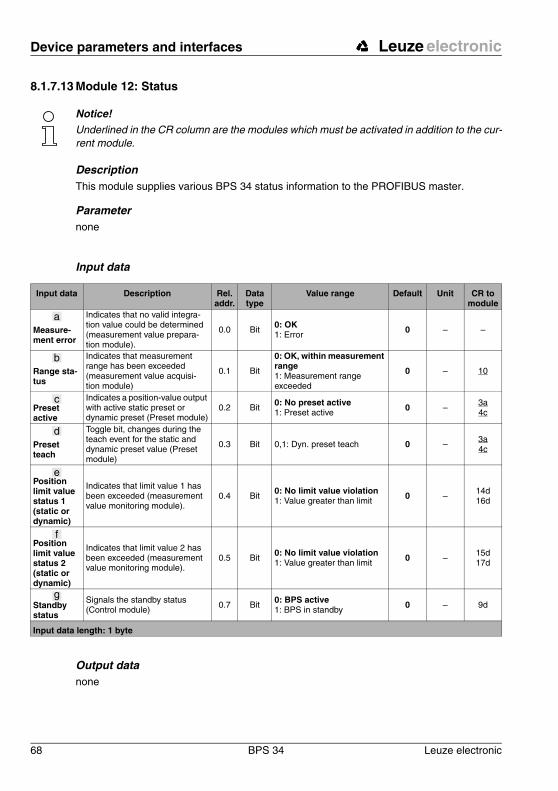
Device parameters and interfaces Leuze electronic
68 BPS 34 Leuze electronic
8.1.7.13 Module 12: Status
Notice!Underlined in the CR column are the modules which must be activated in addition to the cur-rent module.
DescriptionThis module supplies various BPS 34 status information to the PROFIBUS master.
Parameternone
Input data
Output datanone
Input data Description Rel. addr.
Data type
Value range Default Unit CR to module
Measure-ment error
Indicates that no valid integra-tion value could be determined (measurement value prepara-tion module).
0.0 Bit0: OK1: Error 0 – –
Range sta-tus
Indicates that measurement range has been exceeded (measurement value acquisi-tion module)
0.1 Bit
0: OK, within measurement range1: Measurement range exceeded
0 – 10
Preset active
Indicates a position-value output with active static preset or dynamic preset (Preset module)
0.2 Bit0: No preset active1: Preset active 0 –
3a4c
Preset teach
Toggle bit, changes during the teach event for the static and dynamic preset value (Preset module)
0.3 Bit 0,1: Dyn. preset teach 0 –3a4c
Position limit value status 1 (static or dynamic)
Indicates that limit value 1 has been exceeded (measurement value monitoring module).
0.4 Bit0: No limit value violation1: Value greater than limit 0 –
14d16d
Position limit value status 2 (static or dynamic)
Indicates that limit value 2 has been exceeded (measurement value monitoring module).
0.5 Bit0: No limit value violation1: Value greater than limit 0 –
15d17d
Standby status
Signals the standby status (Control module) 0.7 Bit
0: BPS active1: BPS in standby 0 – 9d
Input data length: 1 byte
a
b
c
d
e
f
g
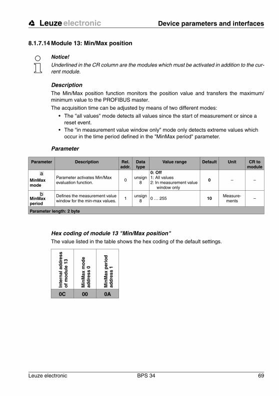
Leuze electronic Device parameters and interfaces
Leuze electronic BPS 34 69
TN
T 3
5/7-
24V
8.1.7.14 Module 13: Min/Max position
Notice!Underlined in the CR column are the modules which must be activated in addition to the cur-rent module.
DescriptionThe Min/Max position function monitors the position value and transfers the maximum/minimum value to the PROFIBUS master.
The acquisition time can be adjusted by means of two different modes:
• The "all values" mode detects all values since the start of measurement or since a reset event.
• The "in measurement value window only" mode only detects extreme values which occur in the time period defined in the "MinMax period" parameter.
Parameter
Hex coding of module 13 "Min/Max position"The value listed in the table shows the hex coding of the default settings.
Parameter Description Rel. addr.
Data type
Value range Default Unit CR to module
MinMax mode
Parameter activates Min/Max evaluation function. 0
unsign8
0: Off1: All values 2: In measurement value
window only
0 – –
MinMax period
Defines the measurement value window for the min-max values. 1
unsign8 0 … 255 10 Measure-
ments –
Parameter length: 2 byte
a
b
Inte
rnal
ad
dre
ss
of
mo
du
le 1
3
Min
Max
mo
de
ad
dre
ss 0
Min
Max
per
iod
ad
dre
ss 1
0C 00 0A

Device parameters and interfaces Leuze electronic
70 BPS 34 Leuze electronic
Input data
Output data
Notice!With "MinMax reset", the input data are reset to 155812h.
With this module, the settings for the Preset (module 3), Offset (module 5) and Scaling (module 6) modules must be taken into account.
Input data Description Rel. addr.
Data type
Value range Default Unit CR to module
Min positionMinimum position for detected period. 0 sign32 -10’000’000 … 10’000’000
0Reset:
2’147’483’647scaled –
Max positionMaximum position for detected period. 4 sign32 -10’000’000 … 10’000’000
0Reset:
-2’147’483’647scaled –
Input data length: 8 byte
c
d
Output data Description Rel. addr.
Data type
Value range Default Unit CR to module
MinMax resetSignal for resetting extreme values
0.0 Bit 0 -> 1: Reset 0 – 7
Output data length: 8 byte
e
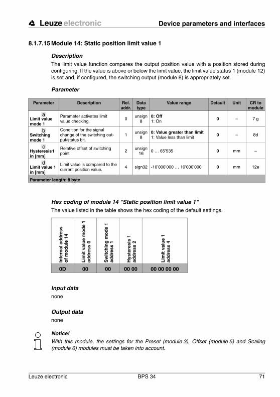
Leuze electronic Device parameters and interfaces
Leuze electronic BPS 34 71
TN
T 3
5/7-
24V
8.1.7.15 Module 14: Static position limit value 1
DescriptionThe limit value function compares the output position value with a position stored during configuring. If the value is above or below the limit value, the limit value status 1 (module 12) is set and, if configured, the switching output (module 8) is appropriately set.
Parameter
Hex coding of module 14 "Static position limit value 1"The value listed in the table shows the hex coding of the default settings.
Input datanone
Output datanone
Notice!With this module, the settings for the Preset (module 3), Offset (module 5) and Scaling (module 6) modules must be taken into account.
Parameter Description Rel. addr.
Data type
Value range Default Unit CR to module
Limit value mode 1
Parameter activates limit value checking. 0
unsign8
0: Off1: On 0 – 7 g
Switching mode 1
Condition for the signal change of the switching out-put/status bit.
1unsign
80: Value greater than limit1: Value less than limit 0 – 8d
Hysteresis 1 in [mm]
Relative offset of switching point 2
unsign16 0 … 65’535 0 mm –
Limit value 1 in [mm]
Limit value is compared to the current position value. 4 sign32 -10’000’000 … 10’000’000 0 mm 12e
Parameter length: 8 byte
a
b
c
d
Inte
rnal
ad
dre
ss
of
mo
du
le 1
4
Lim
it v
alu
e m
od
e 1
ad
dre
ss 0
Sw
itch
ing
mo
de
1
add
ress
1
Hys
tere
sis
1
add
ress
2
Lim
it v
alu
e 1
ad
dre
ss 4
0D 00 00 00 00 00 00 00 00

Device parameters and interfaces Leuze electronic
72 BPS 34 Leuze electronic
8.1.7.16 Module 15: Static position limit value 2
DescriptionThe limit value function compares the output position value with a position stored during parameterisation. If the value is above or below the limit value, the limit value status 2 (module 12) is set and, if configured, the switching output (module 8) is appropriately set.
Parameter
Hex coding of module 15 "Static position limit value 2"The value listed in the table shows the hex coding of the default settings.
Input datanone
Output datanone
Notice!With this module, the settings for the Preset (module 3), Offset (module 5) and Scaling (module 6) modules must be taken into account.
Parameter Description Rel. addr.
Data type
Value range Default Unit CR to module
Limit value mode 2
Parameter activates limit value checking. 0
unsign8
0: Off1: On 0 – 7 g
Switching mode 2
Condition for the signal change of the switching out-put/status bit.
1unsign
80: Value greater than limit1: Value less than limit 0 – 8d
Hysteresis 2 in [mm]
Relative offset of switching point 2
unsign16 0 … 65’535 0 mm –
Limit value 2 in [mm]
Limit value is compared to the current position value. 4 sign32 -10’000’000 … 10’000’000 0 mm 12f
Parameter length: 8 byte
a
b
c
d
Inte
rnal
ad
dre
ss
of
mo
du
le 1
5
Lim
it v
alu
e m
od
e 2
ad
dre
ss 0
Sw
itch
ing
mo
de
2 ad
dre
ss 1
Hys
tere
sis
2 ad
dre
ss 2
Lim
it v
alu
e 2
ad
dre
ss 4
0E 00 00 00 00 00 00 00 00
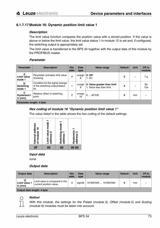
Leuze electronic Device parameters and interfaces
Leuze electronic BPS 34 73
TN
T 3
5/7-
24V
8.1.7.17 Module 16: Dynamic position limit value 1
DescriptionThe limit value function compares the position value with a stored position. If the value is above or below the limit value, the limit value status 1 in module 12 is set and, if configured, the switching output is appropriately set.
The limit value is transferred to the BPS 34 together with the output data of this module by the PROFIBUS master.
Parameter
Hex coding of module 16 "Dynamic position limit value 1"The value listed in the table shows the hex coding of the default settings.
Input datanone
Output data
Notice!With this module, the settings for the Preset (module 3), Offset (module 5) and Scaling (module 6) modules must be taken into account.
Parameter Description Rel. addr.
Data type
Value range Default Unit CR to module
Limit value mode 1
Parameter activates limit value checking. 0 unsign
80: Off1: On 0 – 7 g
Switching mode 1
Condition for the signal change of the switching output/status bit.
1 unsign8
0: Value greater than limit1: Value less than limit 0 – 8d
12e
Hysteresis 1 in [mm]
Relative offset of switching point. 2 unsign
16 0 … 65’535 0 mm –
Parameter length: 4 byte
a
b
c
Inte
rnal
ad
dre
ss
of
mo
du
le 1
6
Lim
it v
alu
e m
od
e 1
ad
dre
ss 0
Sw
itch
ing
mo
de
1
add
ress
1
Hys
tere
sis
1
add
ress
2
0F 00 00 00 00
Output data Description Rel. addr.
Data type
Value range Default Unit CR to module
Limit value 1 in [mm]
Limit value is compared to the current position value.
0 sign32 -10’000’000 … 10’000’000 0 mm –
Output data length: 4 byte
d
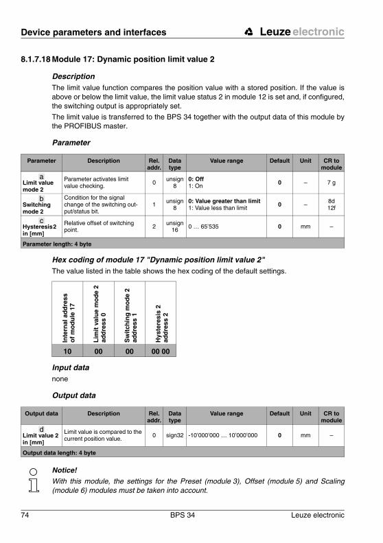
Device parameters and interfaces Leuze electronic
74 BPS 34 Leuze electronic
8.1.7.18 Module 17: Dynamic position limit value 2
DescriptionThe limit value function compares the position value with a stored position. If the value is above or below the limit value, the limit value status 2 in module 12 is set and, if configured, the switching output is appropriately set.
The limit value is transferred to the BPS 34 together with the output data of this module by the PROFIBUS master.
Parameter
Hex coding of module 17 "Dynamic position limit value 2"The value listed in the table shows the hex coding of the default settings.
Input datanone
Output data
Notice!With this module, the settings for the Preset (module 3), Offset (module 5) and Scaling (module 6) modules must be taken into account.
Parameter Description Rel. addr.
Data type
Value range Default Unit CR to module
Limit value mode 2
Parameter activates limit value checking. 0 unsign
80: Off1: On 0 – 7 g
Switching mode 2
Condition for the signal change of the switching out-put/status bit.
1 unsign8
0: Value greater than limit1: Value less than limit 0 – 8d
12f
Hysteresis 2 in [mm]
Relative offset of switching point. 2 unsign
16 0 … 65’535 0 mm –
Parameter length: 4 byte
a
b
c
Inte
rnal
ad
dre
ss
of
mo
du
le 1
7
Lim
it v
alu
e m
od
e 2
ad
dre
ss 0
Sw
itch
ing
mo
de
2 ad
dre
ss 1
Hys
tere
sis
2 ad
dre
ss 2
10 00 00 00 00
Output data Description Rel. addr.
Data type
Value range Default Unit CR to module
Limit value 2 in [mm]
Limit value is compared to the current position value.
0 sign32 -10’000’000 … 10’000’000 0 mm –
Output data length: 4 byte
d
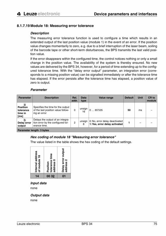
Leuze electronic Device parameters and interfaces
Leuze electronic BPS 34 75
TN
T 3
5/7-
24V
8.1.7.19 Module 18: Measuring error tolerance
DescriptionThe measuring error tolerance function is used to configure a time which results in an extended output of the last position value (module 1) in the event of an error. If the position value changes momentarily to zero, e.g. due to a brief interruption of the laser beam, soiling of the barcode tape or other short-term disturbances, the BPS transmits the last valid posi-tion value.
If the error disappears within the configured time, the control notices nothing or only a small change in the position value. The availability of the system is thereby ensured. No new values are delivered by the BPS 34, however, for a period of time extending up to the config-ured tolerance time. With the "delay error output" parameter, an integration error (corre-sponds to a missing position value) can be signalled immediately or after the tolerance time has elapsed. If the error persists after the tolerance time has elapsed, a position value of zero is output.
Parameter
Hex coding of module 18 "Measuring error tolerance"The value listed in the table shows the hex coding of the default settings.
Input datanone
Output datanone
Parameter Description Rel. addr.
Data type
Value range Default Unit CR to module
Position tolerance time in [ms]
Specifies the time for the output of the last position value follow-ing an error
0 unsign16 0 … 65’535 50 ms –
Delay error output
Delays the output of an integra-tion error by the configured tol-erance time.
2 unsign8
0: No, error delay deactivated1:Yes, error delay activated 1 – –
Parameter length: 3 bytes
a
b
Inte
rnal
ad
dre
ss
of
mo
du
le 1
8
Po
siti
on
to
lera
nce
tim
e
add
ress
0
Del
ay e
rro
r o
utp
ut
ad
dre
ss 2
14 00 32 01
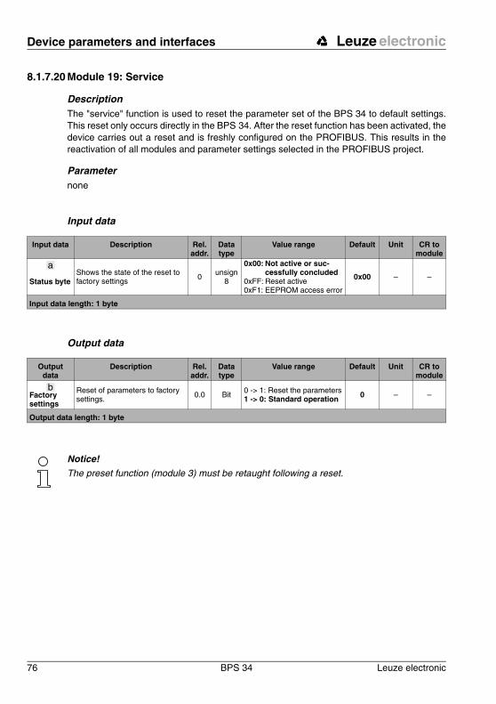
Device parameters and interfaces Leuze electronic
76 BPS 34 Leuze electronic
8.1.7.20 Module 19: Service
DescriptionThe "service" function is used to reset the parameter set of the BPS 34 to default settings. This reset only occurs directly in the BPS 34. After the reset function has been activated, the device carries out a reset and is freshly configured on the PROFIBUS. This results in the reactivation of all modules and parameter settings selected in the PROFIBUS project.
Parameternone
Input data
Output data
Notice!The preset function (module 3) must be retaught following a reset.
Input data Description Rel. addr.
Data type
Value range Default Unit CR to module
Status byteShows the state of the reset to factory settings
0 unsign8
0x00: Not active or suc-cessfully concluded
0xFF: Reset active0xF1: EEPROM access error
0x00 – –
Input data length: 1 byte
a
Output data
Description Rel. addr.
Data type
Value range Default Unit CR to module
Factory settings
Reset of parameters to factory settings.
0.0 Bit 0 -> 1: Reset the parameters1 -> 0: Standard operation 0 – –
Output data length: 1 byte
b
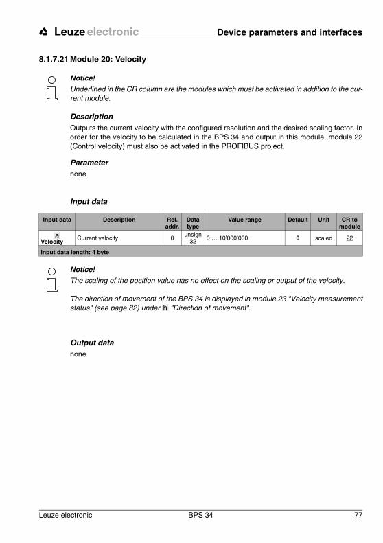
Leuze electronic Device parameters and interfaces
Leuze electronic BPS 34 77
TN
T 3
5/7-
24V
8.1.7.21 Module 20: Velocity
Notice!Underlined in the CR column are the modules which must be activated in addition to the cur-rent module.
DescriptionOutputs the current velocity with the configured resolution and the desired scaling factor. In order for the velocity to be calculated in the BPS 34 and output in this module, module 22 (Control velocity) must also be activated in the PROFIBUS project.
Parameternone
Input data
Notice!The scaling of the position value has no effect on the scaling or output of the velocity.
The direction of movement of the BPS 34 is displayed in module 23 "Velocity measurement status" (see page 82) under "Direction of movement".
Output datanone
Input data Description Rel. addr.
Data type
Value range Default Unit CR to module
VelocityCurrent velocity 0 unsign
32 0 … 10’000’000 0 scaled 22
Input data length: 4 byte
a
h
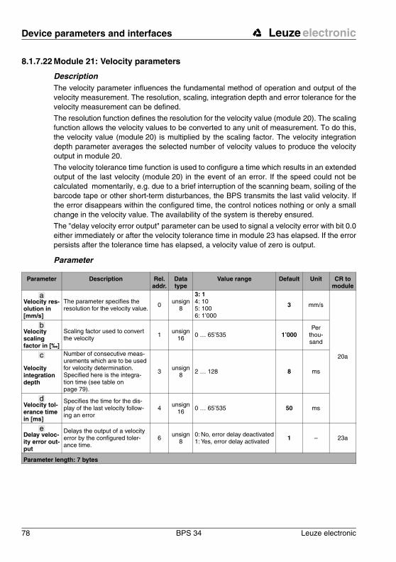
Device parameters and interfaces Leuze electronic
78 BPS 34 Leuze electronic
8.1.7.22 Module 21: Velocity parameters
DescriptionThe velocity parameter influences the fundamental method of operation and output of the velocity measurement. The resolution, scaling, integration depth and error tolerance for the velocity measurement can be defined.
The resolution function defines the resolution for the velocity value (module 20). The scaling function allows the velocity values to be converted to any unit of measurement. To do this, the velocity value (module 20) is multiplied by the scaling factor. The velocity integration depth parameter averages the selected number of velocity values to produce the velocity output in module 20.
The velocity tolerance time function is used to configure a time which results in an extended output of the last velocity (module 20) in the event of an error. If the speed could not be calculated momentarily, e.g. due to a brief interruption of the scanning beam, soiling of the barcode tape or other short-term disturbances, the BPS transmits the last valid velocity. If the error disappears within the configured time, the control notices nothing or only a small change in the velocity value. The availability of the system is thereby ensured.
The "delay velocity error output" parameter can be used to signal a velocity error with bit 0.0 either immediately or after the velocity tolerance time in module 23 has elapsed. If the error persists after the tolerance time has elapsed, a velocity value of zero is output.
Parameter
Parameter Description Rel. addr.
Data type
Value range Default Unit CR to module
Velocity res-olution in [mm/s]
The parameter specifies the resolution for the velocity value. 0 unsign
8
3: 14: 105: 1006: 1’000
3 mm/s
20a
Velocity scaling factor in [‰]
Scaling factor used to convert the velocity 1
unsign16 0 … 65’535 1’000
Per thou-sand
Velocity integration depth
Number of consecutive meas-urements which are to be used for velocity determination. Specified here is the integra-tion time (see table on page 79).
3 unsign8 2 … 128 8 ms
Velocity tol-erance time in [ms]
Specifies the time for the dis-play of the last velocity follow-ing an error
4 unsign16 0 … 65’535 50 ms
Delay veloc-ity error out-put
Delays the output of a velocity error by the configured toler-ance time.
6unsign
80: No, error delay deactivated1: Yes, error delay activated 1 – 23a
Parameter length: 7 bytes
a
b
c
d
e

Leuze electronic Device parameters and interfaces
Leuze electronic BPS 34 79
TN
T 3
5/7-
24V
Hex coding of module 21 "Velocity parameters"The value listed in the table shows the hex coding of the default settings.
Input datanone
Output datanone
Velocity integration depth Integration time [ms]
1 2
2 4
3 6
4 (default) 8
5 10
: :
63 126
64 128
Inte
rnal
ad
dre
ss
of
mo
du
le 2
1
Vel
oci
ty
reso
luti
on
ad
dre
ss 0
Vel
oci
ty
scal
ing
fac
tor
add
ress
1
Vel
oci
ty
inte
gra
tio
n d
epth
ad
dre
ss 3
Vel
oci
ty
tole
ran
ce t
ime
ad
dre
ss 4
Del
ay
velo
city
err
or
ou
tpu
t
add
ress
6
17 03 03 E8 08 00 32 01

Device parameters and interfaces Leuze electronic
80 BPS 34 Leuze electronic
8.1.7.23 Module 22: Velocity measurement control
DescriptionThe control manages the timing of the velocity measurement by starting or stopping the measurement function. Control is performed depending on certain events such as the switching input, time functions or PROFIBUS output bits. Using parameters, it determines the events which influence the states.
Parameter
Hex coding of module 22 "Velocity measurement"The value listed in the table shows the hex coding of the default settings.
Parameter Description Rel. addr.
Data type
Value range Default
Unit CR to module
Velocity measure-ment start mode
The start mode determines by which event the velocity meas-urement is started.
0 unsign8
0: Deactivated1: After initialisation2: Following event:
either by the switching input or by a signal from the PROFIBUS master
0 – 7 g
Velocity measure-ment stop mode
The stop mode determines after which event the velocity meas-urement is stopped.
1unsign
8
0: Deactivated1: By an error2: By a stop event:
either by output bit 0.1 or by the switching input function
0 – 7 g
Parameter length: 2 byte
a
b
Inte
rnal
ad
dre
ss
of
mo
du
le 2
2
Vel
oci
ty m
easu
rem
ent
star
t m
od
e ad
dre
ss 0
Vel
oci
ty m
easu
rem
ent
sto
p m
od
e ad
dre
ss 1
18 00 00

Leuze electronic Device parameters and interfaces
Leuze electronic BPS 34 81
TN
T 3
5/7-
24V
Input data
Notice!These input data signal the state of the BPS 34:
• Init: Base setting during initial startup of the BPS 34• Idle: The BPS 34 is in idle state (scanning beam is off, but motor is running)• Measure: The BPS 34 is in measurement state (data are output in module 1)• Standby: The BPS 34 is in waiting state (laser off and motor off).
Output data
Input data Description Rel. addr.
Data type
Value range Default Unit CR to module
State
Signals the current state of the internal velocity measurement of the BPS 34
0 unsign8
0: Init1: Idle2: Measure4: Standby
0 – –
Input data length: 1 byte
c
Output data
Description Rel. addr.
Data type
Value range Default Unit CR to module
Start event
Event starts velocity measure-ment.
0.0 Bit 0 -> 1: Start 0 – –
Stop eventEvent stops velocity measure-ment.
0.1 Bit 0 -> 1: Stop 0 – –
Min/Max velocity mode
Defines whether the current velocity is included in min/max recording.
0.2 Bit 0: Do not record min/max 1: Record min/max
0 – 24
Min/Max velocity reset
Reset the min/max velocity val-ues. 0.3 Bit 0 -> 1: Reset 0 – 24
Output data length: 1 byte
d
e
f
g
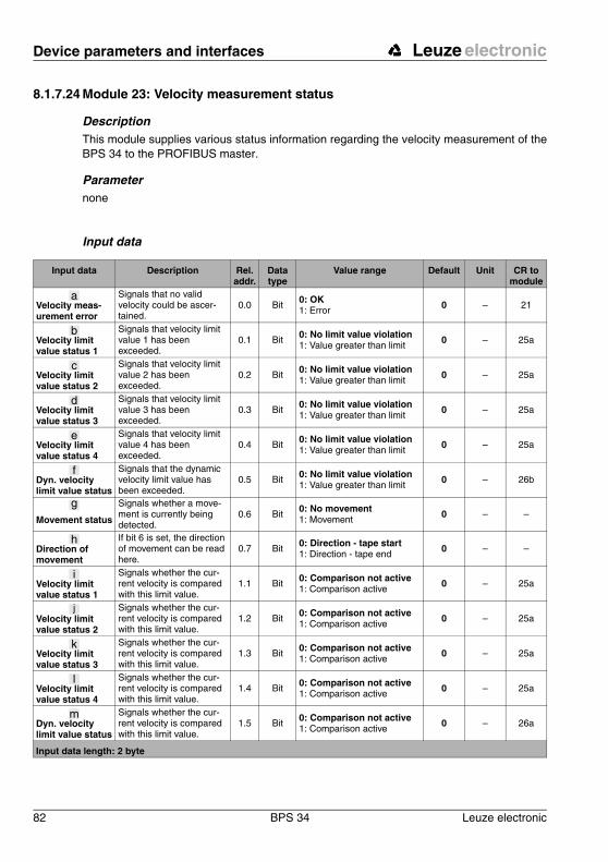
Device parameters and interfaces Leuze electronic
82 BPS 34 Leuze electronic
8.1.7.24 Module 23: Velocity measurement status
DescriptionThis module supplies various status information regarding the velocity measurement of the BPS 34 to the PROFIBUS master.
Parameternone
Input data
Input data Description Rel. addr.
Data type
Value range Default Unit CR to module
Velocity meas-urement error
Signals that no valid velocity could be ascer-tained.
0.0 Bit0: OK1: Error 0 – 21
Velocity limit value status 1
Signals that velocity limit value 1 has been exceeded.
0.1 Bit0: No limit value violation1: Value greater than limit 0 – 25a
Velocity limit value status 2
Signals that velocity limit value 2 has been exceeded.
0.2 Bit0: No limit value violation1: Value greater than limit 0 – 25a
Velocity limit value status 3
Signals that velocity limit value 3 has been exceeded.
0.3 Bit0: No limit value violation1: Value greater than limit 0 – 25a
Velocity limit value status 4
Signals that velocity limit value 4 has been exceeded.
0.4 Bit0: No limit value violation1: Value greater than limit 0 – 25a
Dyn. velocity limit value status
Signals that the dynamic velocity limit value has been exceeded.
0.5 Bit 0: No limit value violation1: Value greater than limit 0 – 26b
Movement status
Signals whether a move-ment is currently being detected.
0.6 Bit0: No movement1: Movement 0 – –
Direction of movement
If bit 6 is set, the direction of movement can be read here.
0.7 Bit 0: Direction - tape start1: Direction - tape end
0 – –
Velocity limit value status 1
Signals whether the cur-rent velocity is compared with this limit value.
1.1 Bit 0: Comparison not active1: Comparison active
0 – 25a
Velocity limit value status 2
Signals whether the cur-rent velocity is compared with this limit value.
1.2 Bit 0: Comparison not active1: Comparison active
0 – 25a
Velocity limit value status 3
Signals whether the cur-rent velocity is compared with this limit value.
1.3 Bit 0: Comparison not active1: Comparison active
0 – 25a
Velocity limit value status 4
Signals whether the cur-rent velocity is compared with this limit value.
1.4 Bit 0: Comparison not active1: Comparison active
0 – 25a
Dyn. velocity limit value status
Signals whether the cur-rent velocity is compared with this limit value.
1.5 Bit 0: Comparison not active1: Comparison active
0 – 26a
Input data length: 2 byte
a
b
c
d
e
f
g
h
i
j
k
l
m
Leuze electronic Device parameters and interfaces
Leuze electronic BPS 34 83
TN
T 3
5/7-
24V
Notice!The movement status is displayed for velocities from 0.01 m/s.
Attention!The "Dynamic preset" module (module 4), the "MVS label" function and the "error tolerance time" can be used to activate the … messages of the input data. Depending on the con-figuration, these may be normal states.
Output datanone
g
a f

Device parameters and interfaces Leuze electronic
84 BPS 34 Leuze electronic
8.1.7.25 Module 24: Min/Max velocity
DescriptionThe Min/Max velocity function monitors the velocity value and transfers the maximum and minimum value to the PROFIBUS master. Recording can be controlled via module 22 "Velocity measurement control". It is also possible to reset values to the initialisation value via module 22.
Parameternone
Input data
Output datanone
Input data Description Rel. addr.
Data type
Value range Default Unit CR to module
Minimum velocity
Minimum velocity for detected period.
0 unsign32
0 … 10’000’000 0 scaled
22
Maximum velocity
Maximum velocity for detected period.
4 unsign32
0 … 10’000’000 0 scaled
Input data length: 8 byte
a
b
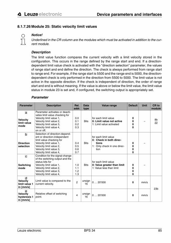
Leuze electronic Device parameters and interfaces
Leuze electronic BPS 34 85
TN
T 3
5/7-
24V
8.1.7.26 Module 25: Static velocity limit values
Notice!Underlined in the CR column are the modules which must be activated in addition to the cur-rent module.
DescriptionThe limit value function compares the current velocity with a limit velocity stored in the configuration. This occurs in the range defined by the range start and end. If a direction-dependent limit value check is activated with the "direction selection" parameter, the values of range start and end define the direction. The check is always performed from range start to range end. For example, if the range start is 5500 and the range end is 5000, the direction-dependent check is only performed in the direction from 5500 to 5000. The limit value is not active in the opposite direction. If the check is independent of direction, the order of range start and end is without meaning. If the value is above or below the limit value, the limit value status in module 23 is set and, if configured, the switching output is appropriately set.
Parameter
Parameter Description Rel. addr.
Data type
Value range Default Unit CR to module
Velocity limit value mode
Parameter activates or deacti-vates limit value checking forVelocity limit value 1,Velocity limit value 2,Velocity limit value 3,Velocity limit value 4,on or off.
0.00.10.20.3
Bitsfor each limit value0: Limit value not active1: Limit value activated
0000
– 8b22
Direction selection
Selection of direction-depend-ent or direction-independent limit value checking forVelocity limit value 1,Velocity limit value 2,Velocity limit value 3,Velocity limit value 4,
0.40.50.60.7
Bits
for each limit value0: Check in both direc-
tions1: Only check in one direc-
tion
0000
–
Switching mode
Condition for the signal change of the switching output and the status bits forVelocity limit value 1,Velocity limit value 2,Velocity limit value 3,Velocity limit value 4,
1.01.11.21.3
Bitsfor each limit value0: Value greater than limit1: Value less than limit
0000
–
Velocity limit value 1 in [mm/s]
Limit value is compared to the current velocity. 2
unsign16 0 … 20’000 0 mm/s
23b
Velocity hysteresis 1 in [mm/s]
Relative offset of switching point.
4 unsign16
0 … 20’000 0 mm/s
a
b
c
d
e
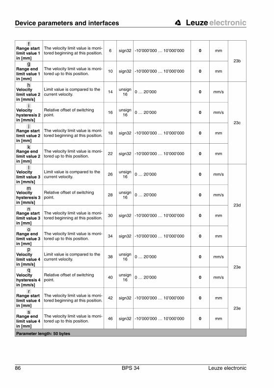
Device parameters and interfaces Leuze electronic
86 BPS 34 Leuze electronic
Range start limit value 1 in [mm]
The velocity limit value is moni-tored beginning at this position. 6 sign32 -10’000’000 … 10’000’000 0 mm
23b
Range end limit value 1 in [mm]
The velocity limit value is moni-tored up to this position.
10 sign32 -10’000’000 … 10’000’000 0 mm
Velocity limit value 2 in [mm/s]
Limit value is compared to the current velocity.
14 unsign16
0 … 20’000 0 mm/s
23c
Velocity hysteresis 2 in [mm/s]
Relative offset of switching point. 16 unsign
16 0 … 20’000 0 mm/s
Range start limit value 2 in [mm]
The velocity limit value is moni-tored beginning at this position. 18 sign32 -10’000’000 … 10’000’000 0 mm
Range end limit value 2 in [mm]
The velocity limit value is moni-tored up to this position.
22 sign32 -10’000’000 … 10’000’000 0 mm
Velocity limit value 3 in [mm/s]
Limit value is compared to the current velocity. 26 unsign
16 0 … 20’000 0 mm/s
23d
Velocity hysteresis 3 in [mm/s]
Relative offset of switching point. 28
unsign16 0 … 20’000 0 mm/s
Range start limit value 3 in [mm]
The velocity limit value is moni-tored beginning at this position. 30 sign32 -10’000’000 … 10’000’000 0 mm
Range end limit value 3 in [mm]
The velocity limit value is moni-tored up to this position.
34 sign32 -10’000’000 … 10’000’000 0 mm
Velocity limit value 4 in [mm/s]
Limit value is compared to the current velocity. 38 unsign
16 0 … 20’000 0 mm/s
23e
Velocity hysteresis 4 in [mm/s]
Relative offset of switching point. 40
unsign16 0 … 20’000 0 mm/s
Range start limit value 4 in [mm]
The velocity limit value is moni-tored beginning at this position.
42 sign32 -10’000’000 … 10’000’000 0 mm
23e
Range end limit value 4 in [mm]
The velocity limit value is moni-tored up to this position.
46 sign32 -10’000’000 … 10’000’000 0 mm
Parameter length: 50 bytes
f
g
h
i
j
k
l
m
n
o
p
q
r
s
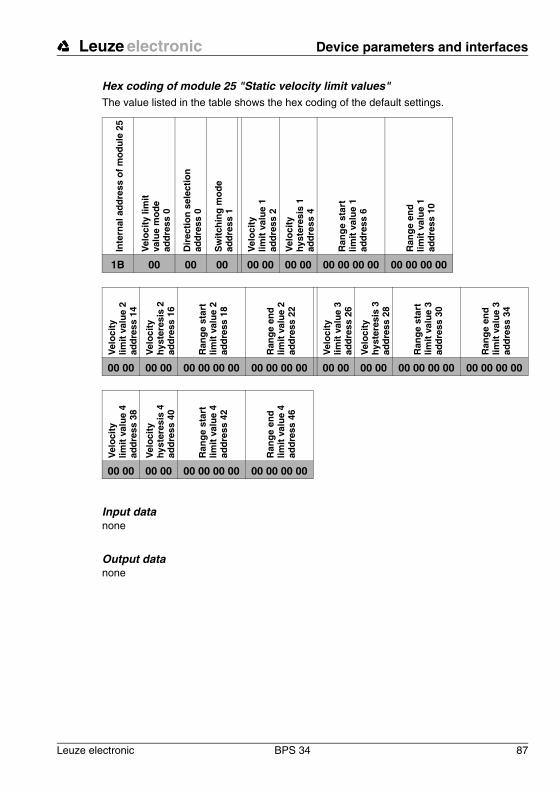
Leuze electronic Device parameters and interfaces
Leuze electronic BPS 34 87
TN
T 3
5/7-
24V
Hex coding of module 25 "Static velocity limit values"The value listed in the table shows the hex coding of the default settings.
Input datanone
Output datanone
Inte
rnal
ad
dre
ss o
f m
od
ule
25
Vel
oci
ty li
mit
va
lue
mo
de
add
ress
0
Dir
ecti
on
sel
ecti
on
ad
dre
ss 0
Sw
itch
ing
mo
de
add
ress
1
Vel
oci
ty
limit
val
ue
1
add
ress
2
Vel
oci
ty
hyst
eres
is 1
ad
dre
ss 4
Ran
ge
star
t
limit
val
ue
1
add
ress
6
Ran
ge
end
lim
it v
alu
e 1
ad
dre
ss 1
0
1B 00 00 00 00 00 00 00 00 00 00 00 00 00 00 00
Vel
oci
ty
limit
val
ue
2
add
ress
14
Vel
oci
ty
hyst
eres
is 2
ad
dre
ss 1
6
Ran
ge
star
t
limit
val
ue
2
add
ress
18
Ran
ge
end
lim
it v
alu
e 2
ad
dre
ss 2
2
Vel
oci
ty
limit
val
ue
3
add
ress
26
Vel
oci
ty
hyst
eres
is 3
ad
dre
ss 2
8
Ran
ge
star
t
limit
val
ue
3
add
ress
30
Ran
ge
end
lim
it v
alu
e 3
ad
dre
ss 3
4
00 00 00 00 00 00 00 00 00 00 00 00 00 00 00 00 00 00 00 00 00 00 00 00
Vel
oci
ty
limit
val
ue
4
add
ress
38
Vel
oci
ty
hyst
eres
is 4
ad
dre
ss 4
0
Ran
ge
star
t
limit
val
ue
4
add
ress
42
Ran
ge
end
lim
it v
alu
e 4
ad
dre
ss 4
6
00 00 00 00 00 00 00 00 00 00 00 00
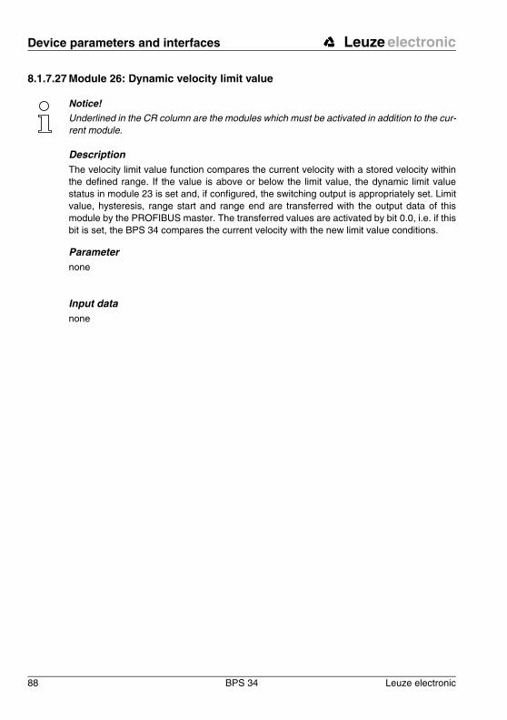
Device parameters and interfaces Leuze electronic
88 BPS 34 Leuze electronic
8.1.7.27 Module 26: Dynamic velocity limit value
Notice!Underlined in the CR column are the modules which must be activated in addition to the cur-rent module.
DescriptionThe velocity limit value function compares the current velocity with a stored velocity within the defined range. If the value is above or below the limit value, the dynamic limit value status in module 23 is set and, if configured, the switching output is appropriately set. Limit value, hysteresis, range start and range end are transferred with the output data of this module by the PROFIBUS master. The transferred values are activated by bit 0.0, i.e. if this bit is set, the BPS 34 compares the current velocity with the new limit value conditions.
Parameternone
Input datanone
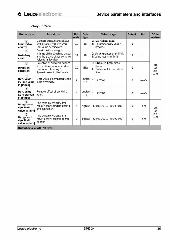
Leuze electronic Device parameters and interfaces
Leuze electronic BPS 34 89
TN
T 3
5/7-
24V
Output data
Output data Description Rel. addr.
Data type
Value range Default Unit CR to module
Limit value control
Controls internal processing of the transferred dynamic limit value parameters.
0.0 Bit0: Do not process1: Parameter now valid /
process0 –
8d2223f
23m
Switching mode
Condition for the signal change of the switching output and the status bit for dynamic velocity limit value.
0.1 Bit 0: Value greater than limit1: Value less than limit 0 –
Direction selection
Selection of direction-depend-ent or direction-independent limit value checking for dynamic velocity limit value
0.2 Bits
0: Check in both direc-tions
1: Only check in one direc-tion
0 –
Dyn. veloc-ity limit value in [mm/s]
Limit value is compared to the current velocity.
1 unsign16
0 … 20’000 0 mm/s
Dyn. veloc-ity hysteresis in [mm/s]
Relative offset of switching point. 3 unsign
16 0 … 20’000 0 mm/s
Range start dyn. limit value in [mm]
The dynamic velocity limit value is monitored beginning at this position.
5 sign32 -10’000’000 … 10’000’000 0 mm8d2223f
23mRange end dyn. limit value in [mm]
The dynamic velocity limit value is monitored up to this position.
9 sign32 -10’000’000 … 10’000’000 0 mm
Output data length: 13 byte
a
b
c
d
e
f
g
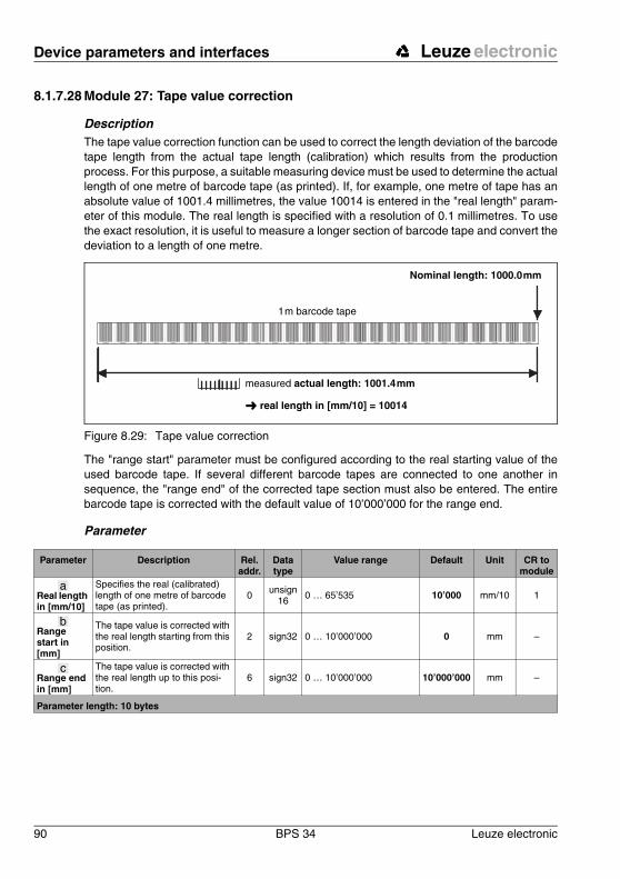
Device parameters and interfaces Leuze electronic
90 BPS 34 Leuze electronic
8.1.7.28 Module 27: Tape value correction
DescriptionThe tape value correction function can be used to correct the length deviation of the barcode tape length from the actual tape length (calibration) which results from the production process. For this purpose, a suitable measuring device must be used to determine the actual length of one metre of barcode tape (as printed). If, for example, one metre of tape has an absolute value of 1001.4 millimetres, the value 10014 is entered in the "real length" param-eter of this module. The real length is specified with a resolution of 0.1 millimetres. To use the exact resolution, it is useful to measure a longer section of barcode tape and convert the deviation to a length of one metre.
Figure 8.29: Tape value correction
The "range start" parameter must be configured according to the real starting value of the used barcode tape. If several different barcode tapes are connected to one another in sequence, the "range end" of the corrected tape section must also be entered. The entire barcode tape is corrected with the default value of 10’000’000 for the range end.
Parameter
000000 000004 000008 000012 000016 000020 000024 000028 000032 000036 000040 000044 000048 000052 000056 000060 000064 000068 000072 000076 000080 000084 000088 000092 000096 000100
1 m barcode tape
Nominal length: 1000.0 mm
measured actual length: 1001.4 mm
� real length in [mm/10] = 10014
Parameter Description Rel. addr.
Data type
Value range Default Unit CR to module
Real length in [mm/10]
Specifies the real (calibrated) length of one metre of barcode tape (as printed).
0 unsign16
0 … 65’535 10’000 mm/10 1
Range start in [mm]
The tape value is corrected with the real length starting from this position.
2 sign32 0 … 10’000’000 0 mm –
Range end in [mm]
The tape value is corrected with the real length up to this posi-tion.
6 sign32 0 … 10’000’000 10’000’000 mm –
Parameter length: 10 bytes
a
b
c
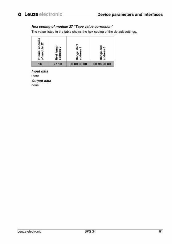
Leuze electronic Device parameters and interfaces
Leuze electronic BPS 34 91
TN
T 3
5/7-
24V
Hex coding of module 27 "Tape value correction"The value listed in the table shows the hex coding of the default settings.
Input datanone
Output datanone
Inte
rnal
ad
dre
ss
of
mo
du
le 2
7
Rea
l len
gth
ad
dre
ss 0
Ran
ge
star
t
add
ress
2
Ran
ge
end
ad
dre
ss 6
1D 27 10 00 00 00 00 00 98 96 80
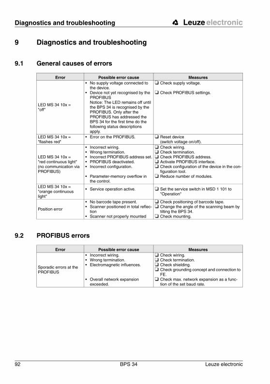
Diagnostics and troubleshooting Leuze electronic
92 BPS 34 Leuze electronic
9 Diagnostics and troubleshooting
9.1 General causes of errors
9.2 PROFIBUS errors
Error Possible error cause Measures
LED MS 34 10x = "off"
• No supply voltage connected to the device.
• Device not yet recognised by the PROFIBUS Notice: The LED remains off until the BPS 34 is recognised by the PROFIBUS. Only after the PROFIBUS has addressed the BPS 34 for the first time do the following status descriptions apply.
❏ Check supply voltage.
❏ Check PROFIBUS settings.
LED MS 34 10x = "flashes red"
• Error on the PROFIBUS. ❏ Reset device (switch voltage on/off).
LED MS 34 10x = "red continuous light" (no communication via PROFIBUS)
• Incorrect wiring.• Wrong termination.• Incorrect PROFIBUS address set.• PROFIBUS deactivated.• Incorrect configuration.
• Parameter-memory overflow in the control.
❏ Check wiring.❏ Check termination.❏ Check PROFIBUS address.❏ Activate PROFIBUS interface.❏ Check configuration of the device in the con-
figuration tool.❏ Reduce number of modules.
LED MS 34 10x = "orange continuous light"
• Service operation active. ❏ Set the service switch in MSD 1 101 to "Operation"
Position error
• No barcode tape present.• Scanner positioned in total reflec-
tion• Scanner not properly mounted
❏ Check positioning of barcode tape.❏ Change the angle of the scanning beam by
tilting the BPS 34.❏ Check mounting.
Error Possible error cause Measures
Sporadic errors at the PROFIBUS
• Incorrect wiring.• Wrong termination. • Electromagnetic influences.
• Overall network expansion exceeded.
❏ Check wiring.❏ Check termination.❏ Check shielding.❏ Check grounding concept and connection to
FE.❏ Check max. network expansion as a func-
tion of the set baud rate.

Leuze electronic Diagnostics and troubleshooting
Leuze electronic BPS 34 93
TN
T 3
5/7-
24V
Notice!Please use page 92 and page 93 as a master copy should servicing be required. Cross the items in the "Measures" column which you have already examined, fill out the fol-lowing address field and fax both pages together with your service contract to the fax number listed below.
Customer data (please complete) Leuze service fax number: +49 7021 573-199
Device type:
Company:
Contact partner / department:
Phone (direct):
Fax:
Street / No:
ZIP code/City:
Country:
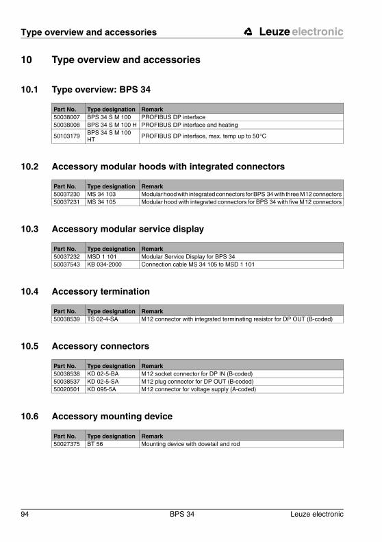
Type overview and accessories Leuze electronic
94 BPS 34 Leuze electronic
10 Type overview and accessories
10.1 Type overview: BPS 34
10.2 Accessory modular hoods with integrated connectors
10.3 Accessory modular service display
10.4 Accessory termination
10.5 Accessory connectors
10.6 Accessory mounting device
Part No. Type designation Remark50038007 BPS 34 S M 100 PROFIBUS DP interface50038008 BPS 34 S M 100 H PROFIBUS DP interface and heating
50103179 BPS 34 S M 100 HT
PROFIBUS DP interface, max. temp up to 50 °C
Part No. Type designation Remark50037230 MS 34 103 Modular hood with integrated connectors for BPS 34 with three M 12 connectors50037231 MS 34 105 Modular hood with integrated connectors for BPS 34 with five M 12 connectors
Part No. Type designation Remark50037232 MSD 1 101 Modular Service Display for BPS 3450037543 KB 034-2000 Connection cable MS 34 105 to MSD 1 101
Part No. Type designation Remark50038539 TS 02-4-SA M 12 connector with integrated terminating resistor for DP OUT (B-coded)
Part No. Type designation Remark50038538 KD 02-5-BA M 12 socket connector for DP IN (B-coded)50038537 KD 02-5-SA M 12 plug connector for DP OUT (B-coded)50020501 KD 095-5A M 12 connector for voltage supply (A-coded)
Part No. Type designation Remark50027375 BT 56 Mounting device with dovetail and rod
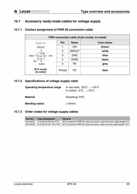
Leuze electronic Type overview and accessories
Leuze electronic BPS 34 95
TN
T 3
5/7-
24V
10.7 Accessory ready-made cables for voltage supply
10.7.1 Contact assignment of PWR IN connection cable
10.7.2 Specifications of voltage supply cable
10.7.3 Order codes for voltage supply cables
PWR connection cable (5-pin socket, A-coded)
Pin Name Core colour
1 VIN brown
2 SWOUT white
3 GND blue
4 SWIN black
5 PE grey
Thread PE bare
PWR IN
SWIN
SWOUT
3
2
1
4
GND VIN
PE
M 12 socket(A-coded)
Operating temperature range in rest state: -30°C … +70°Cin motion: -5°C … +70°C
Material Sheathing: PVC
Bending radius > 50 mm
Part No. Type designation Remark50104557 K-D M12A-5P-5m-PVC M 12 socket for PWR IN, axial connector, open line end, cable length 5 m50104559 K-D M12A-5P-10m-PVC M 12 socket for PWR IN, axial connector, open line end, cable length 10 m

Type overview and accessories Leuze electronic
96 BPS 34 Leuze electronic
10.8 Accessory ready-made cables for PROFIBUS connection
10.8.1 General
• Cable KB PB… for connecting to the DP IN/DP OUT M 12 connector• Standard cables available in lengths from 2 … 30m• Special cables on request.
10.8.2 Contact assignment for PROFIBUS connection cable KB PB…
Figure 10.1:Cable structure of PROFIBUS connection cable
PROFIBUS connection cable (5-pin socket/connector, B-coded)
Pin Name Core colour
1 N.C. –
2 A (N) green
3 N.C. –
4 B (P) red
5 N.C. –
Thread FE bare
N.C. 3
2
1
4N.C.
A (N)
B (P)
N.C.
N.C. 1
2
3
4
A (N)
B (P)
N.C.
N.C.
M 12 socket(B-coded)
M 12 plug(B-coded)
1 Conductor with insulation red 2 Conductor with insulation green 3 Drain wire4 Fibrous fleece
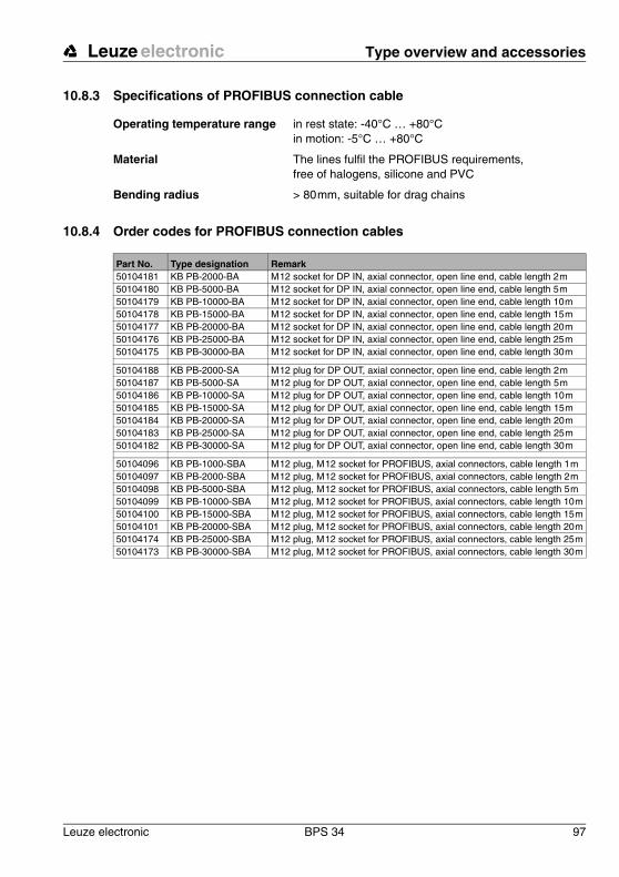
Leuze electronic Type overview and accessories
Leuze electronic BPS 34 97
TN
T 3
5/7-
24V
10.8.3 Specifications of PROFIBUS connection cable
10.8.4 Order codes for PROFIBUS connection cables
Operating temperature range in rest state: -40°C … +80°Cin motion: -5°C … +80°C
Material The lines fulfil the PROFIBUS requirements,free of halogens, silicone and PVC
Bending radius > 80 mm, suitable for drag chains
Part No. Type designation Remark50104181 KB PB-2000-BA M 12 socket for DP IN, axial connector, open line end, cable length 2 m50104180 KB PB-5000-BA M 12 socket for DP IN, axial connector, open line end, cable length 5 m50104179 KB PB-10000-BA M 12 socket for DP IN, axial connector, open line end, cable length 10 m50104178 KB PB-15000-BA M 12 socket for DP IN, axial connector, open line end, cable length 15 m50104177 KB PB-20000-BA M 12 socket for DP IN, axial connector, open line end, cable length 20 m50104176 KB PB-25000-BA M 12 socket for DP IN, axial connector, open line end, cable length 25 m50104175 KB PB-30000-BA M 12 socket for DP IN, axial connector, open line end, cable length 30 m
50104188 KB PB-2000-SA M 12 plug for DP OUT, axial connector, open line end, cable length 2 m50104187 KB PB-5000-SA M 12 plug for DP OUT, axial connector, open line end, cable length 5 m50104186 KB PB-10000-SA M 12 plug for DP OUT, axial connector, open line end, cable length 10 m50104185 KB PB-15000-SA M 12 plug for DP OUT, axial connector, open line end, cable length 15 m50104184 KB PB-20000-SA M 12 plug for DP OUT, axial connector, open line end, cable length 20 m50104183 KB PB-25000-SA M 12 plug for DP OUT, axial connector, open line end, cable length 25 m50104182 KB PB-30000-SA M 12 plug for DP OUT, axial connector, open line end, cable length 30 m
50104096 KB PB-1000-SBA M 12 plug, M 12 socket for PROFIBUS, axial connectors, cable length 1 m50104097 KB PB-2000-SBA M 12 plug, M 12 socket for PROFIBUS, axial connectors, cable length 2 m50104098 KB PB-5000-SBA M 12 plug, M 12 socket for PROFIBUS, axial connectors, cable length 5 m50104099 KB PB-10000-SBA M 12 plug, M 12 socket for PROFIBUS, axial connectors, cable length 10 m50104100 KB PB-15000-SBA M 12 plug, M 12 socket for PROFIBUS, axial connectors, cable length 15 m50104101 KB PB-20000-SBA M 12 plug, M 12 socket for PROFIBUS, axial connectors, cable length 20 m50104174 KB PB-25000-SBA M 12 plug, M 12 socket for PROFIBUS, axial connectors, cable length 25 m50104173 KB PB-30000-SBA M 12 plug, M 12 socket for PROFIBUS, axial connectors, cable length 30 m

Type overview and accessories Leuze electronic
98 BPS 34 Leuze electronic
10.9 Type overview: Barcode tape
Part No. Type designation Remark50038895 BCB 005 Barcode tape, 5 m long50040041 BCB 010 Barcode tape, 10 m long50037489 BCB 020 Barcode tape, 20 m long50037491 BCB 030 Barcode tape, 30 m long50037492 BCB 040 Barcode tape, 40 m long50038894 BCB 050 Barcode tape, 50 m long50038893 BCB 060 Barcode tape, 60 m long50038892 BCB 070 Barcode tape, 70 m long50038891 BCB 080 Barcode tape, 80 m long50038890 BCB 090 Barcode tape, 90 m long50037493 BCB 100 Barcode tape, 100 m long50040042 BCB 110 Barcode tape, 110 m long50040043 BCB 120 Barcode tape, 120 m long50040044 BCB 130 Barcode tape, 130 m long50040045 BCB 140 Barcode tape, 140 m long50040046 BCB 150 Barcode tape, 150 m long50037494 BCB 200 Barcode tape, 200 m long50037495 BCB / special lengths starting at 150 m Barcode tape with special length and special height50102600 BCB special length 25 mm high Barcode tape with special length 25 mm high
Leuze electronic Maintenance
Leuze electronic BPS 34 99
TN
T 3
5/7-
24V
11 Maintenance
11.1 General maintenance informationUsually, the BPS 34 does not require any maintenance by the operator.
In the event of dust build-up, clean the optical window with a soft cloth; use a cleaning agent (commercially available glass cleaner) if necessary.
Also check the barcode tape for possible soiling.
Attention!Do not use solvents and cleaning agents containing acetone. Use of improper cleaning agents can damage the optical window.
11.2 Repairs, servicingRepairs to the device must only be carried out by the manufacturer.
! Contact your Leuze distributor or service organisation should repairs be required. The addresses can be found on the inside of the cover and on the back.
Notice!When sending devices to Leuze electronic for repair, please provide an accurate description of the error.
11.3 Disassembling, packing, disposing
RepackingFor later re-use, the device is to be packed so that it is protected.
Notice!Electrical scrap is a special waste product! Observe the locally applicable regulations re-garding disposal of the product.
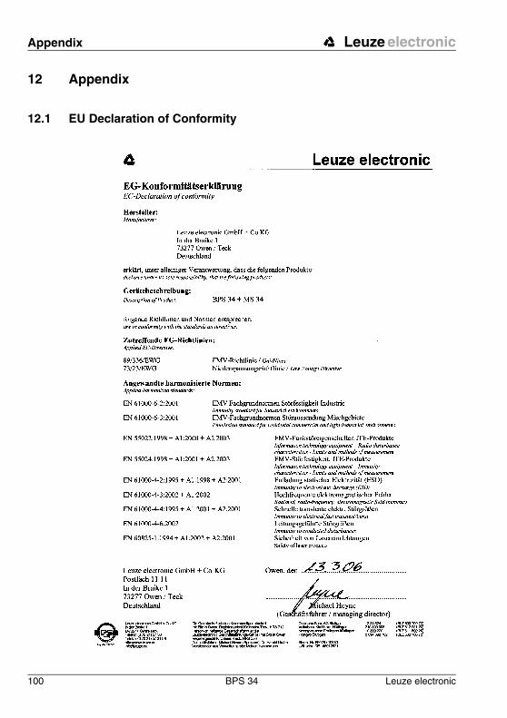
Appendix Leuze electronic
100 BPS 34 Leuze electronic
12 Appendix
12.1 EU Declaration of Conformity
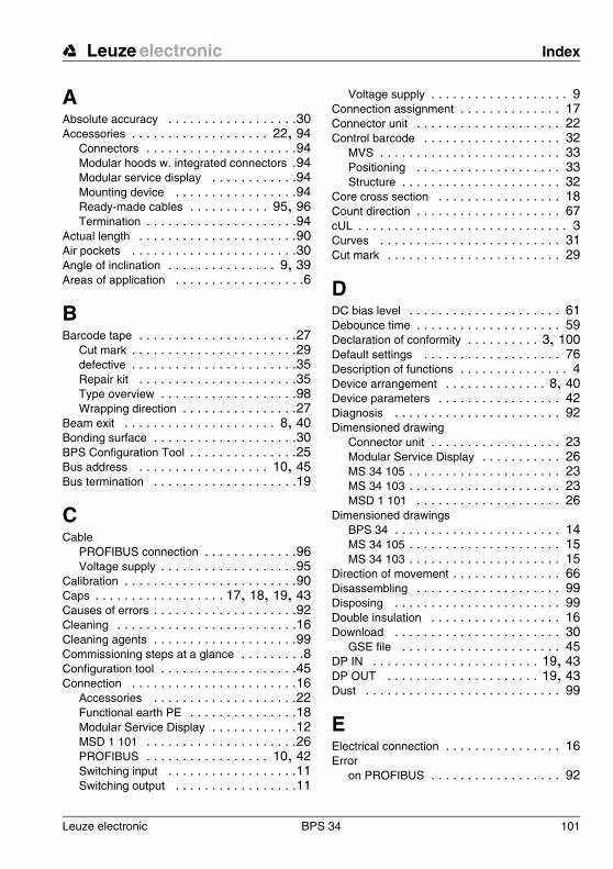
Leuze electronic BPS 34 101
Leuze electronic Index
AAbsolute accuracy . . . . . . . . . . . . . . . . . .30Accessories . . . . . . . . . . . . . . . . . . . 22, 94
Connectors . . . . . . . . . . . . . . . . . . . . .94Modular hoods w. integrated connectors .94Modular service display . . . . . . . . . . . .94Mounting device . . . . . . . . . . . . . . . . .94Ready-made cables . . . . . . . . . . . 95, 96Termination . . . . . . . . . . . . . . . . . . . . .94
Actual length . . . . . . . . . . . . . . . . . . . . . .90Air pockets . . . . . . . . . . . . . . . . . . . . . . .30Angle of inclination . . . . . . . . . . . . . . . 9, 39Areas of application . . . . . . . . . . . . . . . . . .6
BBarcode tape . . . . . . . . . . . . . . . . . . . . . .27
Cut mark . . . . . . . . . . . . . . . . . . . . . . .29defective . . . . . . . . . . . . . . . . . . . . . . .35Repair kit . . . . . . . . . . . . . . . . . . . . . .35Type overview . . . . . . . . . . . . . . . . . . .98Wrapping direction . . . . . . . . . . . . . . . .27
Beam exit . . . . . . . . . . . . . . . . . . . . . 8, 40Bonding surface . . . . . . . . . . . . . . . . . . . .30BPS Configuration Tool . . . . . . . . . . . . . . .25Bus address . . . . . . . . . . . . . . . . . . 10, 45Bus termination . . . . . . . . . . . . . . . . . . . .19
CCable
PROFIBUS connection . . . . . . . . . . . . .96Voltage supply . . . . . . . . . . . . . . . . . . .95
Calibration . . . . . . . . . . . . . . . . . . . . . . . .90Caps . . . . . . . . . . . . . . . . . . 17, 18, 19, 43Causes of errors . . . . . . . . . . . . . . . . . . . .92Cleaning . . . . . . . . . . . . . . . . . . . . . . . . .16Cleaning agents . . . . . . . . . . . . . . . . . . . .99Commissioning steps at a glance . . . . . . . . .8Configuration tool . . . . . . . . . . . . . . . . . . .45Connection . . . . . . . . . . . . . . . . . . . . . . .16
Accessories . . . . . . . . . . . . . . . . . . . .22Functional earth PE . . . . . . . . . . . . . . .18Modular Service Display . . . . . . . . . . . .12MSD 1 101 . . . . . . . . . . . . . . . . . . . . .26PROFIBUS . . . . . . . . . . . . . . . . . 10, 42Switching input . . . . . . . . . . . . . . . . . .11Switching output . . . . . . . . . . . . . . . . .11
Voltage supply . . . . . . . . . . . . . . . . . . . 9Connection assignment . . . . . . . . . . . . . . 17Connector unit . . . . . . . . . . . . . . . . . . . . 22Control barcode . . . . . . . . . . . . . . . . . . . 32
MVS . . . . . . . . . . . . . . . . . . . . . . . . . 33Positioning . . . . . . . . . . . . . . . . . . . . 33Structure . . . . . . . . . . . . . . . . . . . . . . 32
Core cross section . . . . . . . . . . . . . . . . . 18Count direction . . . . . . . . . . . . . . . . . . . . 67cUL . . . . . . . . . . . . . . . . . . . . . . . . . . . . . 3Curves . . . . . . . . . . . . . . . . . . . . . . . . . 31Cut mark . . . . . . . . . . . . . . . . . . . . . . . . 29
DDC bias level . . . . . . . . . . . . . . . . . . . . . 61Debounce time . . . . . . . . . . . . . . . . . . . . 59Declaration of conformity . . . . . . . . . . 3, 100Default settings . . . . . . . . . . . . . . . . . . . 76Description of functions . . . . . . . . . . . . . . . 4Device arrangement . . . . . . . . . . . . . . 8, 40Device parameters . . . . . . . . . . . . . . . . . 42Diagnosis . . . . . . . . . . . . . . . . . . . . . . . 92Dimensioned drawing
Connector unit . . . . . . . . . . . . . . . . . . 23Modular Service Display . . . . . . . . . . . 26MS 34 105 . . . . . . . . . . . . . . . . . . . . . 23MS 34 103 . . . . . . . . . . . . . . . . . . . . . 23MSD 1 101 . . . . . . . . . . . . . . . . . . . . 26
Dimensioned drawingsBPS 34 . . . . . . . . . . . . . . . . . . . . . . . 14MS 34 105 . . . . . . . . . . . . . . . . . . . . . 15MS 34 103 . . . . . . . . . . . . . . . . . . . . . 15
Direction of movement . . . . . . . . . . . . . . . 66Disassembling . . . . . . . . . . . . . . . . . . . . 99Disposing . . . . . . . . . . . . . . . . . . . . . . . 99Double insulation . . . . . . . . . . . . . . . . . . 16Download . . . . . . . . . . . . . . . . . . . . . . . 30
GSE file . . . . . . . . . . . . . . . . . . . . . . 45DP IN . . . . . . . . . . . . . . . . . . . . . . . 19, 43DP OUT . . . . . . . . . . . . . . . . . . . . . 19, 43Dust . . . . . . . . . . . . . . . . . . . . . . . . . . . 99
EElectrical connection . . . . . . . . . . . . . . . . 16Error
on PROFIBUS . . . . . . . . . . . . . . . . . . 92

102 BPS 34 Leuze electronic
Index Leuze electronic
Error case . . . . . . . . . . . . . . . . . . . . . . . .75Error output . . . . . . . . . . . . . . . . . . . . . . .75EU Declaration of Conformity . . . . . . . . . .100Expansion joints . . . . . . . . . . . . . . . . . . . .30
FFactory settings . . . . . . . . . . . . . . . . . . . .76Fastening grooves . . . . . . . . . . . . . . . . . .37Faults . . . . . . . . . . . . . . . . . . . . . . . . . . .16
GGap . . . . . . . . . . . . . . . . . . . . . . . . . . . .29GSE file . . . . . . . . . . . . . . . . . . . . . 42, 45GSE modules
Overview . . . . . . . . . . . . . . . . . . . . . .47Structure . . . . . . . . . . . . . . . . . . . . . . .46
HHeating
Integrated . . . . . . . . . . . . . . . . . . 18, 41Hood with integrated connectors . . . . . . . .22
IInput data . . . . . . . . . . . . . . . . . . . . . . . .42Integrated heating . . . . . . . . . . . . . . . . . .41Integration depth . . . . . . . . . . . . . . . 66, 78Integration error . . . . . . . . . . . . . . . . . . . .75Integration time . . . . . . . . . . . . . . . . . . . .79Intended use . . . . . . . . . . . . . . . . . . . . . . .5Interface
PROFIBUS . . . . . . . . . . . . . . . . . . . . .42
LLaser radiation . . . . . . . . . . . . . . . . . . . . . .6LED states . . . . . . . . . . . . . . . . . . . . . . . .24Length deviation . . . . . . . . . . . . . . . . . . . .90Limit value . . . . . . . . . . . 71, 72, 73, 74, 85Limit velocity . . . . . . . . . . . . . . . . . . . . . .85Limits . . . . . . . . . . . . . . . . . . . . . . . . . . .68
MMaintenance . . . . . . . . . . . . . . . . . . . . . .99Maximum velocity . . . . . . . . . . . . . . . . . . .84
Measurement error . . . . . . . . . . . . . . . . . 68Measurement length . . . . . . . . . . . . . . . . 65Measurement start mode . . . . . . . . . . . . . 63
Velocity . . . . . . . . . . . . . . . . . . . . . . . 80Measurement stop mode . . . . . . . . . . . . . 63
Velocity . . . . . . . . . . . . . . . . . . . . . . . 80Measurement value switching . . . . . . . . . 33Measuring error tolerance . . . . . . . . . . . . 75Minimum velocity . . . . . . . . . . . . . . . . . . 84Modular hood with integrated connectors
MS 34 103 . . . . . . . . . . . . . . . . . . . . 22Modular Service Display . . . . . . . . . . . . . 25Module
Control . . . . . . . . . . . . . . . . . . . . . . . 63Dynamic position limit value 1 . . . . . . . 73Dynamic position limit value 2 . . . . . . . 74Dynamic preset . . . . . . . . . . . . . . . . . 55Dynamic velocity limit value . . . . . . . . . 88Measurement value acquisition . . . . . . 65Measurement value preparation . . . . . . 66Measuring error tolerance . . . . . . . . . . 75Min/Max position . . . . . . . . . . . . . . . . 69Min/Max velocity . . . . . . . . . . . . . . . . 84Offset value . . . . . . . . . . . . . . . . . . . . 56Position value . . . . . . . . . . . . . . . . . . 51Resolution . . . . . . . . . . . . . . . . . . . . . 52Scaling . . . . . . . . . . . . . . . . . . . . . . . 57Service . . . . . . . . . . . . . . . . . . . . . . . 76Static position limit value 1 . . . . . . . . . 71Static position limit value 2 . . . . . . . . . 72Static preset . . . . . . . . . . . . . . . . . . . 53Static velocity limit values . . . . . . . . . . 85Status . . . . . . . . . . . . . . . . . . . . . . . . 68Switching input . . . . . . . . . . . . . . . . . 59Switching output . . . . . . . . . . . . . . . . 61Tape value correction . . . . . . . . . . . . . 90Velocity . . . . . . . . . . . . . . . . . . . . . . . 77Velocity measurement control . . . . . . . 80Velocity measurement status . . . . . . . . 82Velocity parameters . . . . . . . . . . . . . . 78
Modules . . . . . . . . . . . . . . . . . . . . . . . . 47Mounting . . . . . . . . . . . . . . . . . . . . . . . . 37
Angle of inclination . . . . . . . . . . . . . . . 39Barcode tape . . . . . . . . . . . . . . 8, 29, 41BPS 34 . . . . . . . . . . . . . . . . . . . . . . . 37BT 56 . . . . . . . . . . . . . . . . . . . . . . . . 37Device . . . . . . . . . . . . . . . . . . . . . . . . 8Mounting device . . . . . . . . . . . . . . . . . 37
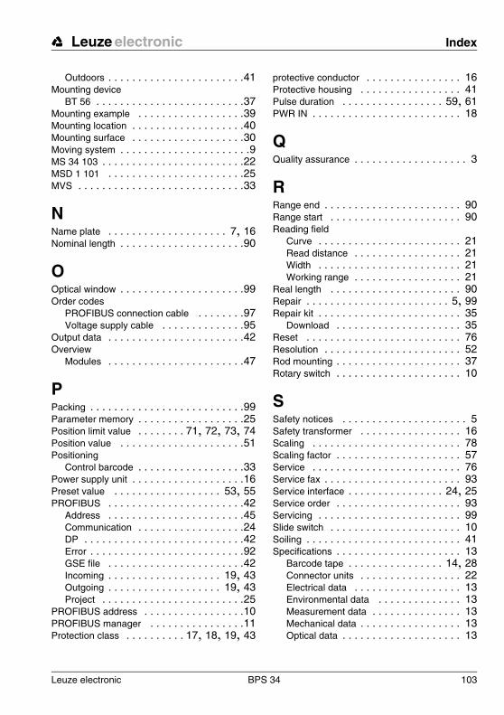
Leuze electronic BPS 34 103
Leuze electronic Index
Outdoors . . . . . . . . . . . . . . . . . . . . . . .41Mounting device
BT 56 . . . . . . . . . . . . . . . . . . . . . . . . .37Mounting example . . . . . . . . . . . . . . . . . .39Mounting location . . . . . . . . . . . . . . . . . . .40Mounting surface . . . . . . . . . . . . . . . . . . .30Moving system . . . . . . . . . . . . . . . . . . . . . .9MS 34 103 . . . . . . . . . . . . . . . . . . . . . . . .22MSD 1 101 . . . . . . . . . . . . . . . . . . . . . . .25MVS . . . . . . . . . . . . . . . . . . . . . . . . . . . .33
NName plate . . . . . . . . . . . . . . . . . . . . 7, 16Nominal length . . . . . . . . . . . . . . . . . . . . .90
OOptical window . . . . . . . . . . . . . . . . . . . . .99Order codes
PROFIBUS connection cable . . . . . . . .97Voltage supply cable . . . . . . . . . . . . . .95
Output data . . . . . . . . . . . . . . . . . . . . . . .42Overview
Modules . . . . . . . . . . . . . . . . . . . . . . .47
PPacking . . . . . . . . . . . . . . . . . . . . . . . . . .99Parameter memory . . . . . . . . . . . . . . . . . .25Position limit value . . . . . . . . 71, 72, 73, 74Position value . . . . . . . . . . . . . . . . . . . . .51Positioning
Control barcode . . . . . . . . . . . . . . . . . .33Power supply unit . . . . . . . . . . . . . . . . . . .16Preset value . . . . . . . . . . . . . . . . . . 53, 55PROFIBUS . . . . . . . . . . . . . . . . . . . . . . .42
Address . . . . . . . . . . . . . . . . . . . . . . .45Communication . . . . . . . . . . . . . . . . . .24DP . . . . . . . . . . . . . . . . . . . . . . . . . . .42Error . . . . . . . . . . . . . . . . . . . . . . . . . .92GSE file . . . . . . . . . . . . . . . . . . . . . . .42Incoming . . . . . . . . . . . . . . . . . . . 19, 43Outgoing . . . . . . . . . . . . . . . . . . . 19, 43Project . . . . . . . . . . . . . . . . . . . . . . . .25
PROFIBUS address . . . . . . . . . . . . . . . . .10PROFIBUS manager . . . . . . . . . . . . . . . .11Protection class . . . . . . . . . . 17, 18, 19, 43
protective conductor . . . . . . . . . . . . . . . . 16Protective housing . . . . . . . . . . . . . . . . . 41Pulse duration . . . . . . . . . . . . . . . . . 59, 61PWR IN . . . . . . . . . . . . . . . . . . . . . . . . . 18
QQuality assurance . . . . . . . . . . . . . . . . . . . 3
RRange end . . . . . . . . . . . . . . . . . . . . . . . 90Range start . . . . . . . . . . . . . . . . . . . . . . 90Reading field
Curve . . . . . . . . . . . . . . . . . . . . . . . . 21Read distance . . . . . . . . . . . . . . . . . . 21Width . . . . . . . . . . . . . . . . . . . . . . . . 21Working range . . . . . . . . . . . . . . . . . . 21
Real length . . . . . . . . . . . . . . . . . . . . . . 90Repair . . . . . . . . . . . . . . . . . . . . . . . . 5, 99Repair kit . . . . . . . . . . . . . . . . . . . . . . . . 35
Download . . . . . . . . . . . . . . . . . . . . . 35Reset . . . . . . . . . . . . . . . . . . . . . . . . . . 76Resolution . . . . . . . . . . . . . . . . . . . . . . . 52Rod mounting . . . . . . . . . . . . . . . . . . . . . 37Rotary switch . . . . . . . . . . . . . . . . . . . . . 10
SSafety notices . . . . . . . . . . . . . . . . . . . . . 5Safety transformer . . . . . . . . . . . . . . . . . 16Scaling . . . . . . . . . . . . . . . . . . . . . . . . . 78Scaling factor . . . . . . . . . . . . . . . . . . . . . 57Service . . . . . . . . . . . . . . . . . . . . . . . . . 76Service fax . . . . . . . . . . . . . . . . . . . . . . . 93Service interface . . . . . . . . . . . . . . . . 24, 25Service order . . . . . . . . . . . . . . . . . . . . . 93Servicing . . . . . . . . . . . . . . . . . . . . . . . . 99Slide switch . . . . . . . . . . . . . . . . . . . . . . 10Soiling . . . . . . . . . . . . . . . . . . . . . . . . . . 41Specifications . . . . . . . . . . . . . . . . . . . . . 13
Barcode tape . . . . . . . . . . . . . . . . 14, 28Connector units . . . . . . . . . . . . . . . . . 22Electrical data . . . . . . . . . . . . . . . . . . 13Environmental data . . . . . . . . . . . . . . 13Measurement data . . . . . . . . . . . . . . . 13Mechanical data . . . . . . . . . . . . . . . . . 13Optical data . . . . . . . . . . . . . . . . . . . . 13
104 BPS 34 Leuze electronic
Index Leuze electronic
PROFIBUS connection cable . . . . . . . .97Voltage supply cable . . . . . . . . . . . . . .95
Start-up delay . . . . . . . . . . . . . . . . . . . . .59Status
PROFIBUS . . . . . . . . . . . . . . . . . . . . .24Status information . . . . . . . . . . . . . . 68, 82Status LED . . . . . . . . . . . . . . . . . . . . . . .24Sub-D connector . . . . . . . . . . . . . . . . . . .26Supply voltage . . . . . . . . . . . . . . . . . . . . .16SW IN/OUT . . . . . . . . . . . . . . . . . . . . . . .20Switching input . . . . . . . . . . . . . . . . . 20, 59Switching output . . . . . . . . . . . . . . . . . . . .20Switch-off delay . . . . . . . . . . . . . . . . . . . .60Switch-off function . . . . . . . . . . . . . . . . . .62Switch-on function . . . . . . . . . . . . . . . . . .61Symbols . . . . . . . . . . . . . . . . . . . . . . . . . .3
TTape height . . . . . . . . . . . . . . . . . . . . 9, 39Tape switching . . . . . . . . . . . . . . . . . . . . .34Tape value correction . . . . . . . . . . . . . . . .90Termination
Connector TS 02-4-SA . . . . . . . . . . . . .19Total reflection . . . . . . . . . . . . . . . . . . . . .40Troubleshooting . . . . . . . . . . . . . . . . . . . .92Type overview . . . . . . . . . . . . . . . . . . . . .94
Barcode tape . . . . . . . . . . . . . . . . . . . .98BPS 34 . . . . . . . . . . . . . . . . . . . . . . . .94
UUniversal module . . . . . . . . . . . . . . . . . . .46
VVelocity . . . . . . . . . . . . . . . . . . . . . . . . . .77Velocity limit value . . . . . . . . . . . . . . . . . .88Velocity measurement . . . . . . . . . 78, 80, 82Velocity parameter . . . . . . . . . . . . . . . . . .78
WWarning label and certification label . . . . . . .7Working range . . . . . . . . . . . . . . . . . . . . .21

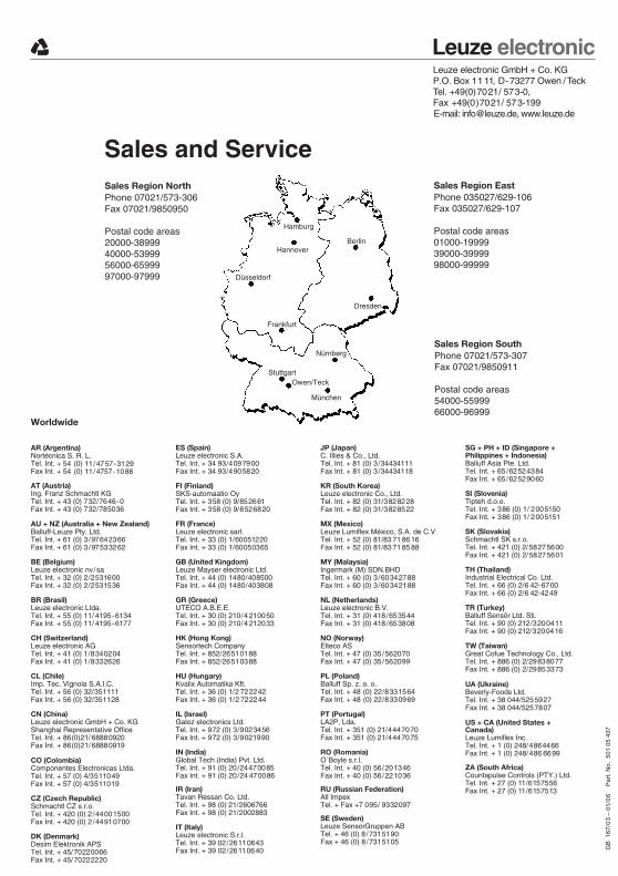
Leuze electronicLeuze electronic GmbH + Co. KGP.O. Box 11 11, D-73277 Owen /TeckTel. +49(0)7021/ 573-0, Fax +49(0)7021/ 573-199E-mail: [email protected], www.leuze.de
Sales and Service
Worldwide
Hamburg
HannoverBerlin
Dresden
Düsseldorf
Frankfurt
StuttgartOwen/Teck
München
Nürnberg
Sales Region NorthPhone 07021/573-306Fax 07021/9850950
Postal code areas20000-3899940000-5399956000-6599997000-97999
Sales Region EastPhone 035027/629-106Fax 035027/629-107
Postal code areas01000-1999939000-3999998000-99999
Sales Region SouthPhone 07021/573-307Fax 07021/9850911
Postal code areas54000-5599966000-96999
GB
167
/03
– 01
/06
P
art.
No.
501
05
437
AT (Austria)Ing. Franz Schmachtl KGTel. Int. + 43 (0) 732/7646-0Fax Int. + 43 (0) 732/785036
AR (Argentina)Nortécnica S. R. L.Tel. Int. + 54 (0) 11/4757-3129Fax Int. + 54 (0) 11/4757-1088
AU + NZ (Australia + New Zealand)Balluff-Leuze Pty. Ltd.Tel. Int. + 61 (0) 3/97642366Fax Int. + 61 (0) 3/97533262
BE (Belgium)Leuze electronic nv/saTel. Int. + 32 (0) 2/2531600Fax Int. + 32 (0) 2/2531536
BR (Brasil)Leuze electronic Ltda.Tel. Int. + 55 (0) 11/ 4195-6134Fax Int. + 55 (0) 11/ 4195-6177
CH (Switzerland)Leuze electronic AGTel. Int. + 41 (0) 1/8340204Fax Int. + 41 (0) 1/8332626
CO (Colombia)Componentes Electronicas Ltda.Tel. Int. + 57 (0) 4/3511049Fax Int. + 57 (0) 4/3511019
CZ (Czech Republic)Schmachtl CZ s.r.o.Tel. Int. + 420 (0) 2/44001500Fax Int. + 420 (0) 2/44910700
DK (Denmark)Desim Elektronik APSTel. Int. + 45/70220066Fax Int. + 45/70222220
ES (Spain)Leuze electronic S.A.Tel. Int. + 34 93/4097900Fax Int. + 34 93/4905820
FI (Finland)SKS-automaatio OyTel. Int. + 358 (0) 9/852661Fax Int. + 358 (0) 9/8526820
CL (Chile)Imp. Tec. Vignola S.A.I.C.Tel. Int. + 56 (0) 32/351111Fax Int. + 56 (0) 32/351128
TW (Taiwan)Great Cofue Technology Co., Ltd.Tel. Int. + 886 (0) 2/29838077Fax Int. + 886 (0) 2/29853373
RU (Russian Federation)All ImpexTel. + Fax +7 095/ 9332097
MY (Malaysia)Ingermark (M) SDN.BHDTel. Int. + 60 (0) 3/60342788Fax Int. + 60 (0) 3/60342188
MX (Mexico)Leuze Lumiflex México, S.A. de C.V.Tel. Int. + 52 (0) 81/83 71 86 16Fax Int. + 52 (0) 81/83 71 85 88
NL (Netherlands)Leuze electronic B.V.Tel. Int. + 31 (0) 418/653544Fax Int. + 31 (0) 418/653808
PT (Portugal)LA2P, Lda.Tel. Int. + 351 (0) 21/4447070Fax Int. + 351 (0) 21/4447075
PL (Poland)Balluff Sp. z. o. o.Tel. Int. + 48 (0) 22/8331564Fax Int. + 48 (0) 22/8330969
RO (Romania)O`Boyle s.r.l.Tel. Int. + 40 (0) 56/201346Fax Int. + 40 (0) 56/221036
SE (Sweden)Leuze SensorGruppen ABTel. + 46 (0) 8/7315190Fax + 46 (0) 8/7315105
CN (China)Leuze electronic GmbH + Co. KGShanghai Representative OfficeTel. Int. + 86(0)21/ 68880920Fax Int. + 86(0)21/ 68880919
SI (Slovenia)Tipteh d.o.o.Tel. Int. + 386 (0) 1/ 2005150Fax Int. + 386 (0) 1/ 2005151
TH (Thailand)Industrial Electrical Co. Ltd.Tel. Int. + 66 (0) 2/6 42-6700Fax Int. + 66 (0) 2/6 42-4249
TR (Turkey)Balluff Sensör Ltd. Sti.Tel. Int. + 90 (0) 212/3200411Fax Int. + 90 (0) 212/3200416
SG + PH + ID (Singapore +
Balluff Asia Pte. Ltd.Tel. Int. + 65/62524384Fax Int. + 65/62529060
Philippines + Indonesia)JP (Japan)C. Illies & Co., Ltd.Tel. Int. + 81 (0) 3 /34434111Fax Int. + 81 (0) 3 /34434118
KR (South Korea)Leuze electronic Co., Ltd.Tel. Int. + 82 (0) 31/3828228Fax Int. + 82 (0) 31/3828522
GB (United Kingdom)Leuze Mayser electronic Ltd.Tel. Int. + 44 (0) 1480/408500Fax Int. + 44 (0) 1480/403808
GR (Greece)UTECO A.B.E.E.Tel. Int. + 30 (0) 210/4 210050Fax Int. + 30 (0) 210/4 212033
HU (Hungary)Kvalix Automatika Kft.Tel. Int. + 36 (0) 1/2 722242Fax Int. + 36 (0) 1/2 722244
HK (Hong Kong)Sensortech CompanyTel. Int. + 852/26510188Fax Int. + 852/26510388
IT (Italy)Leuze electronic S.r.l.Tel. Int. + 39 02/26110643Fax Int. + 39 02/26110640
IL (Israel)Galoz electronics Ltd.Tel. Int. + 972 (0) 3/9023456Fax Int. + 972 (0) 3/9021990
IN (India)Global Tech (India) Pvt. Ltd.Tel. Int. + 91 (0) 20/24470085Fax Int. + 91 (0) 20/24 470086
IR (Iran)Tavan Ressan Co. Ltd.Tel. Int. + 98 (0) 21/2606766Fax Int. + 98 (0) 21/2002883
FR (France)Leuze electronic sarl.Tel. Int. + 33 (0) 1/60051220Fax Int. + 33 (0) 1/60050365
SK (Slovakia)Schmachtl SK s.r.o.Tel. Int. + 421 (0) 2/58275600Fax Int. + 421 (0) 2/58275601
ZA (South Africa)Countapulse Controls (PTY.) Ltd.Tel. Int. + 27 (0) 11/6157556Fax Int. + 27 (0) 11/6157513
US + CA (United States + Canada)Leuze Lumiflex Inc.Tel. Int. + 1 (0) 248/4864466Fax Int. + 1 (0) 248/486 6699
UA (Ukraine)Beverly-Foods Ltd.Tel. Int. + 38 044/5255927Fax Int. + 38 044/5257807
NO (Norway)Elteco ASTel. Int. + 47 (0) 35/562070Fax Int. + 47 (0) 35/562099