Box+Culvert+by+R.S.vasney
17
BOX CULVERT DESIGN NAME OF WORK :- PKN DESIGN INPUT DATA : 1 WIDTH OF EACH BARREL 3.50 m 3500 mm 2 HEIGHT OF EACH BARREL 3.50 m 3500 mm 3 NUMBER OF BARRELS 1 Nos. 4 LIVE LOAD 4.50 4500 5 DEAD LOAD 1.20 1200 6 UNIT WEIGHT OF DRY EARTH 1.80 1800 7 UNIT WEIGHT OF SATURATED EARTH 2.00 2000 8 UNIT WEIGHT OF SUBMERGED EARTH 1.00 1000 9 UNIT WEIGHT OF CONCRETE 2.50 2500 10 30 Degree 11 GRADE OF STEEL Fe 415 12 GRADE OF CONCRETE M 20 13 BANK LEVEL 100.00 m 14 DRAIN H.F.L. 100.00 m 15 LEVEL AT TOP OF BARREL 100.00 M 16 NOMINAL COVER 50 mm 16 REINFORCEMENT For TOP slab Face 20 14.00 cm c/c Dist 10 17.00 cm c/c Center 20 23.00 cm c/c Bottom slab Face 20 11.00 cm c/c Dist 10 17.00 cm c/c Center 20 18.00 cm c/c Vertical wall Face 20 20.00 cm c/c Dist 10 17.00 cm c/c Center 20 -561.00 cm c/c Hench 10 17.00 cm c/c Corner 10 17.00 cm c/c 0.3 20 20 10 14.0 cm c/c 23.0 cm c/c 17.0 cm c/c 0.30 m 20 Corner 20 20 cm c/c 20.0 cm c/c 20 20 ### cm c/c -561.0 cm c/c 10 Hench 10 17 cm c/c 17 cm c/c 20 20 10 11.0 cm c/c 18.0 cm c/c 17 cm c/c t/m 2 kg/m 2 t/m 2 kg/m 2 t/m 3 kg/m 3 t/m 3 kg/m 3 t/m 3 kg/m 3 t/m 3 kg/m 3 ANGLE OF INTERNAL FRICTION ( f ) mm f @ mm f @ mm f @ mm f @ mm f @ mm f @ mm f @ mm f @ mm f @ mm f @ mm f @ mm f @ mm f @ mm f @ mm f @ mm f @ mm f @ mm f @ mm f @ mm f @ mm f @ mm f @ mm f @
-
Upload
paul-singh -
Category
Documents
-
view
21 -
download
6
Transcript of Box+Culvert+by+R.S.vasney
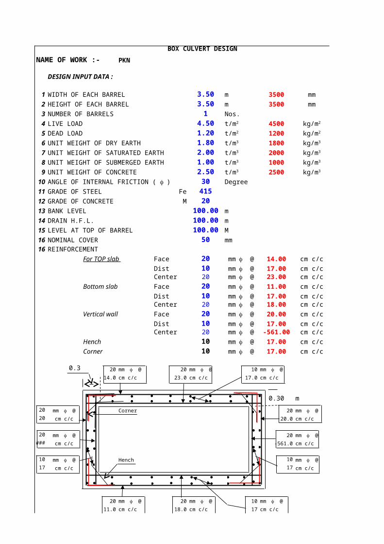
BOX CULVERT DESIGN
NAME OF WORK :- PKN
DESIGN INPUT DATA :
1 WIDTH OF EACH BARREL 3.50 m 3500 mm
2 HEIGHT OF EACH BARREL 3.50 m 3500 mm
3 NUMBER OF BARRELS 1 Nos.
4 LIVE LOAD 4.50 4500
5 DEAD LOAD 1.20 1200
6 UNIT WEIGHT OF DRY EARTH 1.80 1800
7 UNIT WEIGHT OF SATURATED EARTH 2.00 2000
8 UNIT WEIGHT OF SUBMERGED EARTH 1.00 1000
9 UNIT WEIGHT OF CONCRETE 2.50 2500
10 30 Degree
11 GRADE OF STEEL Fe 41512 GRADE OF CONCRETE M 2013 BANK LEVEL 100.00 m
14 DRAIN H.F.L. 100.00 m
15 LEVEL AT TOP OF BARREL 100.00 M
16 NOMINAL COVER 50 mm
16 REINFORCEMENT
For TOP slab Face 20 14.00 cm c/c
Dist 10 17.00 cm c/cCenter 20 23.00 cm c/c
Bottom slab Face 20 11.00 cm c/c
Dist 10 17.00 cm c/cCenter 20 18.00 cm c/c
Vertical wall Face 20 20.00 cm c/c
Dist 10 17.00 cm c/cCenter 20 -561.00 cm c/c
Hench 10 17.00 cm c/c
Corner 10 17.00 cm c/c
0.3 20 20 10
14.0 cm c/c 23.0 cm c/c 17.0 cm c/c
0.30 m
20 Corner 20
20 cm c/c 20.0 cm c/c
20 20
### cm c/c -561.0 cm c/c
10 Hench 10
17 cm c/c 17 cm c/c
20 20 10
11.0 cm c/c 18.0 cm c/c 17 cm c/c
t/m2 kg/m2
t/m2 kg/m2
t/m3 kg/m3
t/m3 kg/m3
t/m3 kg/m3
t/m3 kg/m3
ANGLE OF INTERNAL FRICTION ( f )
mm f @
mm f @mm f @
mm f @
mm f @mm f @
mm f @
mm f @mm f @
mm f @
mm f @
mm f @ mm f @ mm f @
mm f @ mm f @
mm f @ mm f @
mm f @ mm f @
mm f @ mm f @ mm f @

DESIGN NAME OF WORK :- PKN
DESIGN DATA :
1 WIDTH OF EACH BARREL 3.50 m
2 HEIGHT OF EACH BARREL 3.50 m
3 NUMBER OF BARRELS 1 Nos.
4 LIVE LOAD 4.505 DEAD LOAD 1.206 UNIT WEIGHT OF DRY EARTH 1.807 UNIT WEIGHT OF SATURATED EARTH 2.008 UNIT WEIGHT OF SUBMERGED EARTH 1.009 UNIT WEIGHT OF CONCRETE 2.5010 30 Degree
11 GRADE OF STEEL Fe 41512 GRADE OF CONCRETE M 2013 BANK LEVEL 100.00 m
14 DRAIN H.F.L. 100.00 m
15 LEVEL AT TOP OF BARREL 100.00 m
16 NOMINAL COVER 50 mm
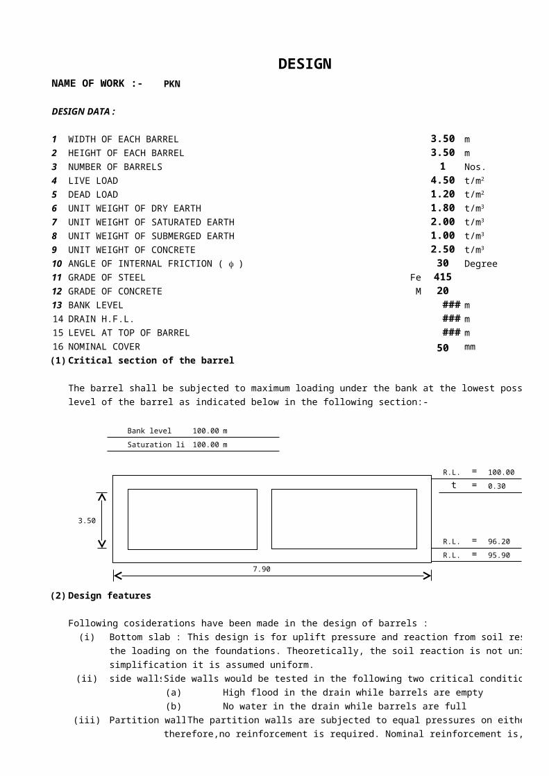
(1) Critical section of the barrel
The barrel shall be subjected to maximum loading under the bank at the lowest possible
level of the barrel as indicated below in the following section:-
Bank level 100.00 m
Saturation line 100.00 m
R.L. = 100.00 m
t = 0.30 m
3.50
R.L. = 96.20 m
R.L. = 95.90 m
7.90
(2) Design features
Following cosiderations have been made in the design of barrels :
(i) Bottom slab : This design is for uplift pressure and reaction from soil resulting from
the loading on the foundations. Theoretically, the soil reaction is not uniform but for
simplification it is assumed uniform.
(ii) side walls : Side walls would be tested in the following two critical conditions
(a) High flood in the drain while barrels are empty
(b) No water in the drain while barrels are full
(iii) Partition walls : The partition walls are subjected to equal pressures on either side, and
therefore,no reinforcement is required. Nominal reinforcement is, however,
t/m2
t/m2
t/m3
t/m3
t/m3
t/m3
ANGLE OF INTERNAL FRICTION ( f )

provided to take care of contingency arising due to unequal pressures
resulting from chocking up of any of the barrels.
(iv) Top slab : The loads considered for design of top slab are :
(a) Earth load,
(b) Weight of water below saturation line
As there is no roadway along the drain, no live load due to traffic shall be considered.
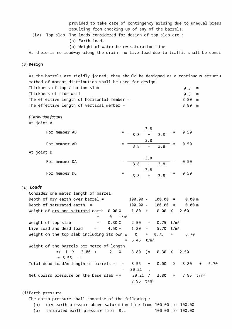
(3) Design
method of moment distribution shall be used for design.
Thickness of top / bottom slab 0.3 m
Thickness of side wall 0.3 m
The effective length of horizontal member = 3.80 m
The effective length of vertical member = 3.80 m
Distribution factors
At joint A
For member AB =3.8
= 0.503.8 + 3.8
For member AD =3.8
= 0.503.8 + 3.8
At joint D
For member DA =3.8
= 0.503.8 + 3.8
For member DC =3.8
= 0.503.8 + 3.8
(i) LoadsConsider one meter length of barrel
Depth of dry earth over barrel = 100.00 - 100.00 = 0.00 m
Depth of saturated earth = 100.00 - 100.00 = 0.00 m
0.00 X 1.80 + 0.00 X 2.00
= 0
Weight of top slab = 0.30 X 2.50 = 0.75
Live load and dead load = 4.50 + 1.20 = 5.70
Weight on the top slab including its own weight = 0 + 0.75 + 5.70
= 6.45
Weight of the barrels per metre of length
=( 1 X 3.80 + 2 X 3.80 )x 0.30 X 2.50
= 8.55 t
Total dead load/m length of barrels = = 8.55 + 0.00 X 3.80 + 5.70 x 3.80
= 30.21 t
Net upward pressure on the base slab = = 30.21 / 3.80 = 7.95
7.95
(ii) Earth pressure
The earth pressure shall comprise of the following :
(a) dry earth pressure above saturation line from R.L. 100.00 to 100.00
(b) saturated earth pressure from R.L. 100.00 to 100.00
As the barrels are rigidly joined, they should be designed as a continuous structure. Hardy Cross
Weight of dry and saturard earth =
t/m2
t/m2
t/m2
t/m2
t/m2
t/m2
= 30 degree , = 1/3
The pressure at A= Surcharge ( due to dry earth + Satured soil + live & dead load )
= h1 + X X h2
+ Cp x
= 1/3 X 1.80 X 0.00 + 1/3 X 1.0 X 0.00
+ 1/3 X 5.70
= 1.90
Pressure at D = 1.90 + X X h1 + Cp x X h2
= 1.90 + 1/3 X 1.00 X 0.00 + 1/3 x 1.80 X 3.80
= 4.18
Loads acting on different members are shown below :
6.45
1.90 1.90
3.80 3.80
3.80
F
4.18 2.28
7.95
(iii) Fixing moments
6.45 X 3.8
(i) On span AB = 12 = 12
= 7.77 t-m
7.95 X 3.8
(ii) On span CD = 12 = 12
= 9.57 t-m
(iii) On span AD fixed end moments in the wall at each end due to rectangular portion
1.90 X 3.8
= 12 = 12
= 2.29 t-m
Fixed end moments due to triangular portion
2.28 X 3.8
= 30
= 1.10 t-m
= 2.28 X 3.8
20
= 1.65 t-m
Total fixed end moments at A = 2.29 + 1.10
= 3.39 t-m
Total fixed end moments at D = 2.29 + 1.65
= 3.94 t-m
(iv) Distribution of moments
Joints C D A B
Member Dc DA AD AB
Distribution factore 0.50 0.50 0.50 0.50
Fixed end -9.57 9.57 -3.94 3.39 -7.77 7.77
moments
Balance -2.82 -2.82 2.19 2.19
Corresponding to f Cp
Cp X wd X Cp ws
WDL,LL
t/m2
Cp ws wd
t/m2
t/m2
t/m2 t/m2
t/m2
t/m2 t/m2
wl2 2
wl2 2
wl2 2
2
MAD
MDA 2
B
D
A
CD
E
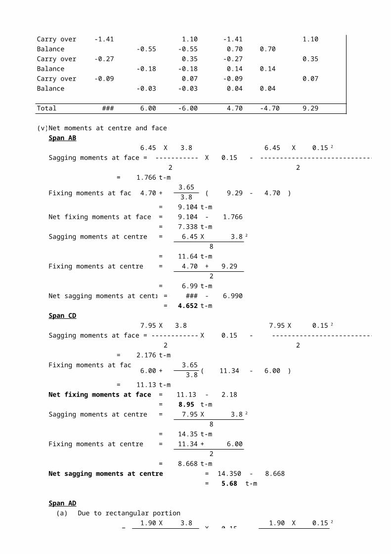
Carry over -1.41 1.09 -1.41 1.09
Balance -0.55 -0.55 0.70 0.70
Carry over -0.27 0.35 -0.27 0.35
Balance -0.18 -0.18 0.14 0.14
Carry over -0.09 0.07 -0.09 0.07
Balance -0.03 -0.03 0.04 0.04
Total -11.34 6.00 -6.00 4.70 -4.70 9.29
(v) Net moments at centre and face
Span AB
6.45 X 3.8 6.45 X 0.15
Sagging moments at face = ------------------- X 0.15 - -----------------------------
2 2
= 1.7657 t-m
Fixing moments at face= 4.70 +3.65
( 9.29 - 4.70 )3.8
= 9.1041 t-m
Net fixing moments at face = 9.1041 - 1.766
= 7.3384 t-m
Sagging moments at centre = 6.45 X 3.8
8
= 11.642 t-m
Fixing moments at centre = 4.70 + 9.29
2
= 6.9904 t-m
Net sagging moments at centre = 11.642 - 6.990
= 4.652 t-m
Span CD
7.95 X 3.8 7.95 X 0.15
Sagging moments at face = -------------------- X 0.15 - ----------------------------
2 2
= 2.1763 t-m
Fixing moments at face=6.00 +
3.65( 11.34 - 6.00 )
3.8
= 11.128 t-m
Net fixing moments at face = 11.128 - 2.18
= 8.95 t-m
Sagging moments at centre = 7.95 X 3.8
8
= 14.35 t-m
Fixing moments at centre = 11.34 + 6.00
2
= 8.6683 t-m
Net sagging moments at centre = 14.350 - 8.668
= 5.68 t-m
Span AD
(a) Due to rectangular portion
=1.90 X 3.8
X 0.15 -1.90 X 0.15
2
2
2
2
2

=2
X 0.15 -2
= 0.5201 t-m
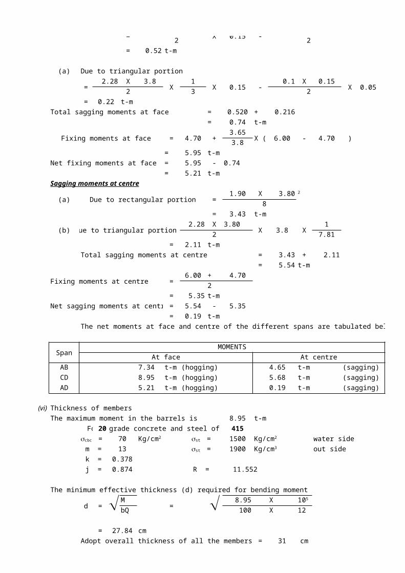
(a) Due to triangular portion
=2.28 X 3.8
X1
X 0.15 -0.1 X 0.15
X 0.052 3 2
= 0.22 t-m
Total sagging moments at face = 0.520 + 0.216
= 0.74 t-m
Fixing moments at face = 4.70 +3.65
X ( 6.00 - 4.70 )3.8
= 5.95 t-m
Net fixing moments at face = 5.95 - 0.74
= 5.21 t-m
Sagging moments at centre
(a) Due to rectangular portion =1.90 X 3.80
8
= 3.43 t-m
(b) Due to triangular portion =2.28 X 3.80
X 3.8 X1
2 7.81
= 2.11 t-m
Total sagging moments at centre = 3.43 + 2.11
= 5.54 t-m
Fixing moments at centre =6.00 + 4.70
2
= 5.35 t-m
Net sagging moments at centre = 5.54 - 5.35
= 0.19 t-m
The net moments at face and centre of the different spans are tabulated below :
SpanMOMENTS
At face At centre
AB 7.34 t-m (hogging) 4.65 t-m (sagging)
CD 8.95 t-m (hogging) 5.68 t-m (sagging)
AD 5.21 t-m (hogging) 0.19 t-m (sagging)
(vi) Thickness of members
The maximum moment in the barrels is 8.95 t-m
For M 20 grade concrete and steel of Fe 415
70 1500 water side
m = 13 1900 out side
k = 0.378
j = 0.874 R = 11.552
The minimum effective thickness (d) required for bending moment
d = ÖM= Ö 8.95 X
bQ 100 X 12
= 27.84 cm
Adopt overall thickness of all the members = 31 cm
2
scbc = Kg/cm2 sst = Kg/cm2
sst = Kg/cm3
105
Then effective thickness = 26 cm
(clear cover = 5.0 cm )
The reinforcement required at various points is given below :
(vii) Reinforcement
Span AB (Top Horizontal Slab)
Moments in t-m Reinforcement required
At face 7.34 t-m (hogging) = 21.53
Provide 20 mm bars @ 14.0 cm c/c
At centre 4.65 t-m (sagging) = 13.65
Provide 20 mm bars @ 23.0 cm c/c
Distribution Provide 10 mm bars @ 17.0 cm c/c
Span CD (Bottom Horizontal Slab)
Moments in t-m Reinforcement required
At face 8.95 t-m (hogging) = 26.26
Provide 20 mm bars @ 11.0 cm c/c
At centre 5.68 t-m (sagging) = 16.67
Provide 20 mm bars @ 18.0 cm c/c
Distribution Provide 10 mm bars @ 17.0 cm c/c
Span AD (vertical wall)
Moments in t-m Reinforcement required
At face 5.21 t-m (hogging) = 15.28
Provide 20 mm bars @ 20.0 cm c/c
At centre 0.19 t-m (sagging) = -0.56
Provide 20 mm bars @ -561.0 cm c/c
Distribution Provide 10 mm bars @ 17.0 cm c/c
Hench ### mm Provide 10 mm bars @ 17.0 cm c/c
corner Provide 10 mm bars @ 17.0 cm c/c
Nominal steel shall also be provided on the outer face of the walls for the condition when there is
no water in the drain and barrels are running full. The details of reinforcement are shown below
20 14.0 cm c/c
20 14 cm c/c
10 17.0 cm c/c
A 20 23 cm c/c B E
0.30
C.C. M - 20 20 -561 cm c/c 8 17.0 cm c/c 3.50
20 20 cm c/c
D F 0.30
C
20 11 cm c/c clear cover = 5.00 cm
20 18 cm c/c
A t Cm2
A t Cm2
A t Cm2
A t Cm2
A t Cm2
A t Cm2
mm f @
mm f @
mm f @
mm f @
mm f @ mm f @
mm f @
mm f @
mm f @
0.30 3.50 m 0.30 3.50 0.30
DETAILS OF REINFORCEMENT IN BARREL
20 14.0 cm c/c
10 17.0 cm c/c
20 23 cm c/c
20 18 cm c/c
10 mm bars @ 20 20 cm c/c 17 cm c/c
3.5
0
10 mm bars @ 17 cm c/c
20 18 cm c/c
20 11 cm c/c 10 mm bars @
17 cm c/c
0.30 3.50 0.30
mm f @
mm f @
mm f @
mm f @
mm f @
mm f @
mm f @