
BOXCAR Version 3 Manual - maine.gov · references are available for the hydraulic design of box...
101
BOXCAR Version 3 2010 Program Guide
-
Upload
truongtram -
Category
Documents
-
view
215 -
download
0
Transcript of BOXCAR Version 3 Manual - maine.gov · references are available for the hydraulic design of box...

BOXCAR Version 3
2010
Program Guide

2
Introduction BOXCAR is a computer program that performs structural analysis and reinforcement design for single cell reinforced concrete box culverts. The name BOXCAR is derived from the phrase "BOX Culvert Analysis and Reinforcing design." Internal dimensions of box culverts are sized based on consideration of hydraulic requirements and site characteristics and are then used as input to BOXCAR. Loads considered are culvert self-weight, vertical and lateral earth pressure, gravity effect of internal fluid, live loads, and user defined surcharge loads. User controlled input includes geometry, material properties and most design parameters. Design may be completed in accordance with the provisions of the AASHTO LRFD Bridge Design Specifications, the AAASHTO Standard Specifications for Highway Bridges, or the Canadian Highway Bridge Design Code. Additionally the input parameters of the AASHTO Standard Specifications can be configured to design in accordance with the AREMA Manual of Railway Engineering. A large number of references are available for the hydraulic design of box culverts.
BOXCAR completes the structural analysis and design of box sections by:
(1) computing loads on the structure, (2) applying the calculated loads to the structure through assumed pressure distributions, (3) completing a structural analysis, and (4) designing reinforcement to carry the resulting moments thrusts and shears.
Other structural analysis programs are available that model the structure and the soil using the finite element technique; however, these programs offer a level of sophistication that is not generally required for typical design situations. They may be useful to evaluate special conditions.
BOXCAR is intended to be a design tool for the practicing engineer. For routine designs the engineer may input as little information as the span, rise, and depth of fill, and utilize a default file to generate the remainder of the input. The user may modify the default file to quickly create input files with typical input parameters. For non-standard designs the user can override the default input parameters to address the special conditions of a particular project. The user may quickly evaluate the effects of varying any of the input parameters to select the optimum design for a particular set of conditions. Because of its flexibility, BOXCAR is intended for use by engineers. Many of the input values require knowledge of design specifications which the user must be familiar with. To emphasize this BOXCAR prints the following warnings with all output files:
The successful application and use of this software product is dependent on the application of skilled engineering judgment and is the responsibility of the user. The user must select input values suitable to his specific installation. Use of default parameters does not assure a safe design for all installations. The information presented in the computer output is for review, interpretation, application, and approval by a qualified engineer.
ANY IMPLIED OR EXPRESS WARRANTIES COVERING THE SOFTWARE PROGRAM OR PROGRAM HELP FILE INCLUDING ANY WARRANTIES OF MERCHANTABILITY OR FITNESS FOR A PARTICULAR PURPOSE ARE EXPRESSLY EXCLUDED. SIMPSON GUMPERTZ & HEGER INC., THE AMERICAN CONCRETE PIPE ASSOCIATION, AND THE FEDERAL HIGHWAY ADMINISTRATION SHALL NOT BE LIABLE FOR SPECIAL INCIDENTAL, CONSEQUENTIAL, INDIRECT OR OTHER SIMILAR DAMAGES ARISING FROM BREACH OF WARRANTY BREACH OF CONTRACT OR OTHER LEGAL THEORY EVEN IF SUCH PARTIES HAVE BEEN ADVISED OF SUCH DAMAGES.
This manual assumes the user has some basic understanding of computer usage and the Windows environment.

3
History of BOXCAR
BOXCAR and a similar program, PIPECAR (for the design of reinforced concrete pipe culverts), were first released in 1982 as part of a Federal Highway Administration (FHWA) project to develop standard designs for improved inlets, and were detailed in the report Structural Design Manual for Improved Inlets and Culverts (Reference 1). As originally released, BOXCAR ran only on mainframe computers, and did not include any provisions for treatment of live loads
BOXCAR was developed from the programs used to generate the standard box culvert designs contained in American Association of State Highway and Transportation Officials (AASHTO) Standards M 259 and M 273, which are the same as ASTM Standards C 789 and C 850, respectively. The ASTM standards have been combined into the current C 1433 standard. These earlier standards are based on the AASHTO Standard Specifications for Highway Bridges,. A companion standard based on the LRFD Bridge Design Specifications C 1577 has been added These standards provide required reinforcement for precast concrete box sections reinforced with welded wire fabric and buried between zero and about 6 m (20 ft).
The original programs used the American Concrete Institute ultimate strength design method for obtaining steel areas. The development of these programs and test programs used to verify their designs is well documented (Reference 2, Reference 3, and Reference 4). This original work was carried out under the sponsorship of the American Concrete Pipe Association and Wire Reinforcement Institute.
Subsequent to the development of the AASHTO Culvert Standards, AASHTO developed standards for box sections that have been included in the Standard Specifications for Highway Bridges, and the LRFD Bridge Design Specifications. BOXCAR Version 3 allows users to design according to either of these specifications.
BOXCAR Version 3:
operates in the MS Windows (95/98/2000/XP/Vista) environment.
allows user specified surcharge loads for special design situations
allows considerable freedom in specifying live loads, including truck magnitudes, tire footprints, impact loads, and distribution of live load with increasing depth of fill,
incorporates lane loads,
provides detailed output to screen and printer on user selected input parameters, loads, design forces and reinforcement design, and
provides graphical output of the general reinforcement layout.
NOTE: Comparison of BOXCAR V3.0 output to previous versions of BOXCAR and to ASTM C 1433 Table 2 for Interstate Live Load Conditions
Although not explicitly stated in either BOXCAR Version 2 output or the ASTM C 1433 Standard, designs for an Interstate live load represent the controlling steel areas for checks of BOTH an AASHTO HS-20 live load AND an INTERSTATE LIVE LOAD. BOXCAR VERSION 3.0 PERMITS THE USER TO SELECT THE INTERSTATE LIVE LOAD OR THE HS-20 LIVE LOAD CONFIGURATION INDEPENDENTLY (AS WELL AS SELECTION OF BOTH LIVE LOAD CHECKS FOR THE SAME RUN). IF BOXCAR 3.0 IS RUN WITH ONLY THE

4
INTERSTATE LIVE LOAD SELECTED THEN THE HS-20 CONDITION WILL NOT BE EVALUATED. FOR COMPARISON OF BOXCAR VERSION 3 DESIGNS TO BOXCAR VERSION 2 OR THE C 1433 TABLE 2 DESIGNS THE USER MUST SELECT BOTH THE HS-20 AND THE INTERSTATE LIVE LOADS.

5
CULVERT GEOMETRY See Culvert Geometry Figure.
Haunch dimensions - Haunch dimensions can be specified separately for the top and bottom haunches. The vertical and horizontal dimensions of haunches do not need to be equal, mm (in.). Note that for 45 degree and deep (at the base) haunches shear is checked relative to the tip of the haunch. For shallow base haunches (or no haunches) shear is checked relative to the face of the wall.
Length of culvert - Laying length of manufactured culverts. Used in BOXCAR to limit live load strip widths for culverts buried less than 0.6 m (2 ft). For cast-in-place culverts set the length of culvert to a value greater than 3 m (10 ft).
Rise of culvert - Interior height of the culvert. The allowable range of rises is 0.6 m to 6.1 m (2 ft to 25 ft).
Slab and wall thickness - The thickness of the top slab, bottom slab or sidewalls of the culvert, mm (in.).
Span of culvert - Interior span of the culvert. The allowable range of spans is 1 m to 6.1 m (3 ft to 25 ft)
Depth of Fill
See Culvert Geometry Figure.
Height of earth cover from the ground or highway surface to the top of the culvert, m (ft).
For railroad loading, depth of fill is measured from the bottom of the tie, with a minimum allowable depth of fill equal to 0.46m (1.5ft) .
To design for a single depth of fill, enter a Minimum depth of fill and hit enter without making an entry for the Maximum depth of fill, or enter the maximum depth of fill equal to the minimum depth. To design for multiple depths of fill enter both the minimum and maximum depths of fill and the Depth increment. BOXCAR can complete designs for up to 45 depths of fill in a single run.

6

7
REINFORCEMENT LAYOUT
See Reinforcement Layout Figure.
AS1 - Sidewall outside face reinforcement
AS2 - Top slab inside face reinforcement
AS3 - Bottom slab inside face reinforcement
AS4 - Sidewall inside face reinforcement
AS5 - Top slab inside face longitudinal (distribution) reinforcement. Required only in box sections with depths of less than or equal to 0.6 m (2 ft).
AS6 - Top slab outside face longitudinal (distribution) reinforcement. Required only in box sections with depths of less than or equal to 0.6 m (2 ft).
AS7 - Top slab outside face reinforcement
AS8 - Bottom slab outside face reinforcement
Concrete Cover - The depth of the clear concrete over the main reinforcement.
Reinforcing Diameters - The reinforcing diameter is used to compute the depth from the compression face to the centroid of the tension reinforcing, d. BOXCAR assumes the centroid of the tension reinforcement is at the mid-depth of the reinforcing diameter value input. d = member thickness - cover- reinforcing diameter / 2
If multiple layers of reinforcement are used, the reinforcing diameter should be set to give the proper clear cover and to calculate the proper centroid.
If the actual reinforcement diameter required by the design area and spacing is larger than the value used as input, revise the diameter to a larger number and re-run BOXCAR.
Reinforcing Spacing - The maximum center to center spacing of main reinforcement. If the reinforcing design is governed by crack control, the user may be able to reduce the required area by decreasing the reinforcing spacing mm, (in.).

8
Note: Lap lengths, ld must be added by user to extensions provided in BOXCAR output

9
REINFORCED CONCRETE DESIGN Reinforced Concrete Design Methodology The reinforced concrete design methodology used in BOXCAR is presented as extracts from the AASHTO Standard Specifications, and the AASHTO LRFD Specifications, and the AREMA design specifications as appropriate. The original development of designs for precast box sections and verification of these designs is well documented, See the References. Flexure Design Service Load Flexural Requirements Shear Strength Requirements Shear Strength Requirements - AASHTO LRFD / CHBDC Stirrup Design Ultimate Flexural Strength Methodology Reinforcement required for flexural resistance is calculated using Equations from AASHTO Standard LRFD requirements for concrete pipe. These equations are applicable to standard flexural design of straight sections and are preferred here because of the convenient form, which treats the effect of axial thrust forces. See Heger and McGrath (1982).
where g = 0.85 bf'c Note : For the CHBDC code the above equation is modified as follows: 1) φf is removed from the equation 2) g = α φc bf'c where α = maximum (0.67, 0.85 - 100 / 1000 * f'c (psi) φc = Material Resistance factor for concrete 3) fy = φsfy where φs = Material Resistance factor for steel
Minimum flexural reinforcing: Asmin = .002bh
Maximum flexural reinforcing limited by concrete compression. This provision assures that the maximum reinforcement does not exceed 75% of bal, thus assuring a ductile failure mode. This limit is calculated for all design codes.

10
Design for Shear Strength without Stirrups
Several approaches to evaluation of shear (diagonal tension) strength are used, based on the depth of fill and the design code (AASHTO Standard or LRFD, or CHBDC. Note: Design per the AASHTO Standard Code conforms to AREMA for railroad loadings) selected by the user. See the Shear Design Method for the AASHTO Standard Code.or for the AASHTO LRFD Code and the CHBDC.
Shear strength is initially evaluated using simplified methods. If the demand exceeds the capacity of the simplified method, BOXCAR evaluates capacity using the more detailed methods permitted by the code. If the ultimate shear exceeds the capacity of the concrete shear strength, BOXCAR investigates the benefits of increasing the shear capacity using additional flexural steel and, if necessary, designs stirrup reinforcing to satisfy the demand. Shear strength is evaluated at all sections and is typically controlled at the specified Shear Design locations shown in the Design Sections Figure.
AASHTO Standard Code with less than 0.6 m (2 ft) - For the top slab, BOXCAR checks special code provisions for slabs and bridge slabs where, provided loading and minimum thickness requirements are met, the section is empirically considered satisfactory for shear. Note that similar provisions in the LRFD code are not incorporated into the BOXCAR program.
If the special provisions are not applicable, then the allowable shear in the top slab and bottom slab is computed as the greater of Article 8.16.6.2.1 Eq. 8-48 or 8-49. Allowable shear in the walls is calculated as the greater of Article 8.16.6.2 Eq. 8-50 or 8-51. Shear strength for concrete is not less than 2 times the square root of f'c.
AASHTO LRFD and Standard Code with more than 0.6 m (2 ft) - The shear capacity of the top and bottom slabs is calculated per LRFD Code Article 5.14.5.3, Eq. 3-1 or Standard Code 8.16.6.7 Eq. 8-59) with a minimum limit of 3 times the square root of f'c and a maximum of 4 times the the square root of f'c.
If shear demands are not satisfied by concrete strength then BOXCAR proceeds with stirrup design.

11
Stirrup Design
BOXCAR will proceed with stirrup design if it determines that the shear strength of the slabs or sidewalls is inadequate. Design will be based on the developable stirrup yield stress and the stirrup spacing input by the user. Design calculations are described in the Section on Stirrup Design Calculations.
The top slab, bottom slab, top of the sidewall and bottom of the sidewall are all considered separately. A requirement of stirrup reinforcement at one of these locations does not require stirrup reinforcement at any of the others. BOXCAR determines the required area of each line of stirrups, the number of required lines of stirrups, and starting point where stirrups are required, either at the tip of the haunch or the face of the wall.
Stirrup Design Calculations If the shear strength is exceeded, stirrups may be designed to carry the excess shear forces. Shear reinforcement is calculated as follows:
Calculate the required capacity of the shear reinforcement, Vs:
for the AASHTO Standard Code Vs = Vu / φ - Vc AASHTO Standard Code 8.16.6.3.1 For the AASHTO LRFD Code and the CHBDC Code Determine the required, Vs based on the provided flexural steel, and moment, thrust, and shear at the design section. See AASHTO LRFD Eq. 5.8.3.5-1 and CHBDC Clause 8.9.3.11 for details for the calculation
Calculate the required shear steel area, Av: Av = (Vs * s) / (fv * d) AASHTO Standard Code 8.16.6.3 Eq. 8-53 Av = Vs * s * Tan(θ) / (fv * dv) AASHTO LRFD eq. 5.8.3.3-4, CHBDC Clause 8.9.3.5
Caculate minimum shear steel, Avmin: Avmin = 50 * b * s / fv AASHTO Standard Code 8.19.1.2 Eq. 8-64 Avmin = .0316 * sqrt(fc, ksi) * b * s / fv AASHTO LRFD Code eq 5.8.2.5-1 Avmin = .02285 * sqrt(fc, ksi) * b * s / fv CHBDC 8.9.1.3
Check for maximum shear capacity allowed for shear steel, Vsmax: VsMax = 8 * Sqr(fc) * bw * d AASHTO Standard Code 8.16.6.3.9

12
For the AASHTO LRFD Code and the CHBDC Code Vsmax = Vn -Vc with Vn limitied to: Vn = 0.25 * fc * b * dv AASHTO LRFD eq. 5.8.3.3-2, CHBDC Clause 8.9.3.3 Note: If Vs > Vsmax the design is not possible. The BOXCAR output does not provide a reinforcing design. Calculate maximum spacing of shear reinforcing, smax: smax = d / 2 < 24 in. unless Vs > 4 sqrt(fc) *b * d, then smax = smax / 2 AASHTO 8.19.3 and 8.16.6.3.8 For the AASHTO LRFD Code and the CHBDC Code Spacing of shear reinforcement is dependent on the shear stress in the concrete: AASHTO LRFD 5.8.2.7 vu = Vu / (φ * b *dv) If vu < 0.125 * fc smax = lesser of 0.8 * dv or 24 in. If vu >= 0.125 * fc smax = lesser of 0.4 * dv or 12 in. CHBDC 8.14.6 If Vu <= 0.1 * fc * φ * b *dv) smax = lesser of 0.75 * dv or 600mm. If Vu > 0.1 * fc * φ * b *dv) smax = lesser of 0.33 * dv or 300mm.

13
CONCRETE
Material Properties
Concrete Density - Unit weight of concrete, kN/m3, (lbs/ft3). The concrete density is used to compute loads due to culvert self weight. If designing box sections used as vertical shafts, the self weight does not contribute to moments, thus the concrete density may be set to a low value, such as 0.01.
Concrete Strength - compressive strength of concrete used for design, MPa (psi).
Main Reinforcement Type - this value is used to evaluate crack provisions for the CHBDC. (Clause 7.8.9.1) Main Reinforcement Yield Strength - Yield strength of flexural reinforcement, parallel to the span of the culvert, MPa (ksi).
Soil Unit Weight - Unit weight of soil, kN/m3, (lb/ft3).
Stirrup Reinforcement Yield Strength – Developable yield strength of the stirrup reinforcement. The value input must reflect the strength of the stirrup anchorage, MPa (psi)
14
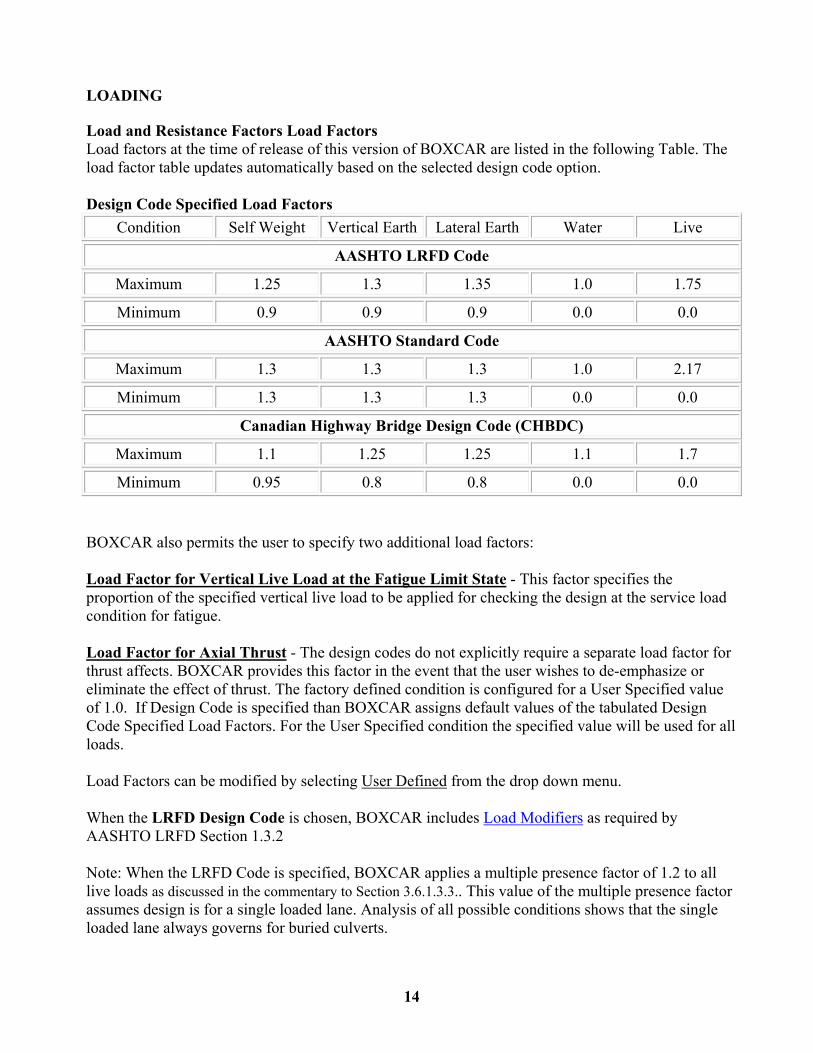
LOADING Load and Resistance Factors Load Factors Load factors at the time of release of this version of BOXCAR are listed in the following Table. The load factor table updates automatically based on the selected design code option. Design Code Specified Load Factors
Condition Self Weight Vertical Earth Lateral Earth Water Live
AASHTO LRFD Code
Maximum 1.25 1.3 1.35 1.0 1.75
Minimum 0.9 0.9 0.9 0.0 0.0
AASHTO Standard Code
Maximum 1.3 1.3 1.3 1.0 2.17
Minimum 1.3 1.3 1.3 0.0 0.0
Canadian Highway Bridge Design Code (CHBDC)
Maximum 1.1 1.25 1.25 1.1 1.7
Minimum 0.95 0.8 0.8 0.0 0.0
BOXCAR also permits the user to specify two additional load factors: Load Factor for Vertical Live Load at the Fatigue Limit State - This factor specifies the proportion of the specified vertical live load to be applied for checking the design at the service load condition for fatigue. Load Factor for Axial Thrust - The design codes do not explicitly require a separate load factor for thrust affects. BOXCAR provides this factor in the event that the user wishes to de-emphasize or eliminate the effect of thrust. The factory defined condition is configured for a User Specified value of 1.0. If Design Code is specified than BOXCAR assigns default values of the tabulated Design Code Specified Load Factors. For the User Specified condition the specified value will be used for all loads. Load Factors can be modified by selecting User Defined from the drop down menu. When the LRFD Design Code is chosen, BOXCAR includes Load Modifiers as required by AASHTO LRFD Section 1.3.2 Note: When the LRFD Code is specified, BOXCAR applies a multiple presence factor of 1.2 to all live loads as discussed in the commentary to Section 3.6.1.3.3.. This value of the multiple presence factor assumes design is for a single loaded lane. Analysis of all possible conditions shows that the single loaded lane always governs for buried culverts.

15
Resistance Factors - BOXCAR provides resistance factors for flexure effects and for shear effects. At the time of release of this Version of BOXCAR, AASHTO provides separate factors for precast and cast-in-place box culverts, as provided in the following table. Design Code Specified Resistance Factors
Force Effect
AASHTO Standard and LRFD Codes
Cast-in-Place Precast
CHBDC*
Flexure (CHBDC - Steel) 0.90 1.00 0.90
Shear (CHBDC- Concrete) 0.85 0.90 0.75
Compression (CHBDC Concrete) Not Applicable 0.75
* - Materials Resistance Factors CHBDC (Clause 8.4.6)
Load Modifiers (LRFD Only)
The AASHTO LRFD Bridge Design Specification provides for modifying loads based on ductility, redundance, and importance. BOXCAR allows input for a single load modifier which is a user developed composite of the effect of the three individual modifiers. BOXCAR allows input for four load modifiers, one for each of the load factors.
AASHTO LRFD Load Modifiers
Condition Self Weight Vertical Earth Lateral Earth Water Live
Values 1.0 1.05 1.05 1.0 1.0
Load Modifiers can be changed using the "Edit" button.

16
Load Combinations Table
The Load Combinations Table identifies the combinations of the basic load cases that will be analyzed. The default configuration analyzes three load combination cases and one fatigue case. The three default cases are:
1. Maximum Vertical Loads and Maximum Horizontal Loads 2. Maximum Vertical Loads and Minimum Horizontal Loads 3. Minimum Vertical Loads and Maximum Horizontal Loads
The table can be edited and users can specify custom load combinations by selecting the "User Defined" option.
Loads are either applied as "Min" or "Max" or not applied "0.0".
BOXCAR will create a service and ultimate load case for each defined Load Combination.
Applied loads are combined with load factor =1.0 for the service condition and are combined using the specified Minimum or Maximum Load Factor for the respective basic load case.
Loading Cases used in Analysis
BOXCAR completes a separate analysis for the effect of each load condition listed in Load Conditions (table) and shown graphically in Load Conditions (figure). For purposes of computing maximum design forces at each design location, the load cases are grouped into three categories:
1. Permanent Dead Loads - Permanent dead loads are considered to be acting on the structure at all times. Service forces due to permanent dead loads are modified by the dead load factors to determine the factored forces.
2. Additional Dead Loads - Additional dead loads are considered to be acting on the structure only if they increase the design force at the design section being considered. Service forces due to additional dead loads are modified by the dead load factors to determine the factored ultimate forces.
3. Live Loads - Live loads are considered to be acting on the structure only if they increase the design force at the design section being considered. Service forces due to live loads are modified by the live load factors to determine the factored forces.
Note that the surcharge load cases may be assigned by the user into any of the three load groups.

17

18
Load Conditions Table
See Load Conditions Figure
Permanent dead loads are always applied to the structure
Load case 1 = Culvert self weight
Load case 2 = Vertical soil weight
Load case 3 = Minimum lateral soil pressure
Additional dead loads are applied only if they increase the design forces
Load case 4 = Internal fluid weight (gravity only)
Load case 5 = Additional lateral soil pressure
Live loads are applied only if they increase the design forces
Load case 6 = Uniform HS-Series truck load or railroad locomotive load
Load case 7 = Uniform interstate/tandem truck load
Load case 8 = Approaching vehicle load
Load cases 11 to 21 = Live load 1 truck load (11 truck positions over culvert)
CHBDC CL-W or Tandem / Tridem truck with reference axle 1
Load cases 22 to 32 = Live load 2 truck load (11 truck positions over culvert)
CHBDC CL-W or Tandem / Tridem truck with reference axle 2
User specified loads are applied based on the selection of load type.
Surcharge loads can be specified as Permanent dead loads, Additional, dead loads, or Live loads
Load case 9 = Uniform vertical surcharge load
Load case 10 = Linearly varying lateral surcharge load

19
Dead Loads
Dead loads on box sections fall into two general categories: permanent dead loads, which always act on the culvert, and additional dead loads, which are temporary or indeterminate loads. Additional dead loads are only considered if they increase the design force at a particular section.
The configuration of these loads can be see in the Loading Condition Figure.
Permanent dead loads:
Culvert weight is computed based on the user specified wall thickness and concrete density.
Vertical soil load is computed as the soil prism load modified by a vertical arching factor:
Wp = VAF * Wsp
Wsp = So γs H
where:
Wp = load on culvert, kN/m (lbs/ft)
VAF = Vertical Arching Factor, , formerly known as the soil-structure interaction factor and
called Fe in AASHTO
Wsp = soil prism load, kN/m (lbs/ft)
So = outside span of culvert, m, (ft) = Span + 2 ts
ts = thickness of sidewall, m (ft)
γs = unit weight of soil, kN/m3 (lb/ft3)
H = depth of fill, m (ft)
Minimum lateral soil pressure - The minimum lateral soil pressure is a linearly varying pressure applied to the sidewalls of the box culvert. It is computed as:
αmin γs (H + x)
where:
αmin = minimum lateral pressure coefficient
x = the distance from the top of the culvert to the point where pressure is being calculated.

20
See Load Conditions (table) and Load Conditions (figure).
Surcharge Loads - Surcharge loads may be specified by the user directly in kPa (psf). Surcharge loads may
be user specified as permanent dead load. Vertical surcharge pressures are uniformly applied pressures. Lateral
surcharge may be specified as linearly varying pressures.
Additional dead loads:
Additional lateral soil pressure - The additional lateral soil pressure is a linearly varying pressure applied to the sidewalls of the box culvert, computed as:
(αmax - αmin) γs (H + x)
where:
αmax = maximum lateral pressure coefficient
x = the distance from the top of the culvert to the point where pressure is being calculated.
Standard designs in AASHTO M 259 and AASHTO M273 (ASTM C 1433) were completed with αmax = 0.50.
AREA requires αmax = 1.0.
See Load Conditions (table) and Load Conditions (figure).
Internal fluid load - The internal fluid load is the gravity effect of a fluid with a user specified unit weight and depth inside the culvert. No internal pressure may be specified. The user may specify the depth of the fluid and the density of the fluid.
Surcharge Loads - Surcharge loads may be specified by the user directly in kPa (psf - lb/ft for the 1ft section analyzed). Surcharge loads may be user specified as additional dead load, by setting the Application Code. Vertical surcharge pressures are uniformly applied pressures. Lateral surcharge may be specified as linearly varying pressures.

21
LIVE LOADS,
General
BOXCAR may allow more than one live load per run depending on the total number of wheels. Live load selections are automatically disabled for combinations that are not allowed. For each live load type, the user must specify other variables as well. For additional information on these variables, see the help topics for each live load type.
The user may also specify no live load.
Uniform Vertical or linearly varying Surcharge loads may also be designated by the user to be treated as live loads. See discussion of surcharge loads under dead loads and Load Combinations for additional information.
Note: When the LRFD Code is specified, BOXCAR applies a multiple presence factor of 1.2 to live loads as discussed in the commentary to Section 3.6.1.3.3. This value of the multiple presence factor assumes design is for a single loaded lane. Analysis of all possible conditions shows that the single loaded lane always governs for buried culverts. Note:: No multiple presence factor is applied for the second load condition for evaluation of truck direction of travel perpendicular to the span. See discussion below under "Live Load Application in BOXCAR".
NOTE: Comparison of BOXCAR V3.0 output to previous versions of BOXCAR and to ASTM C 1433 Table 2 for Interstate Live Load Conditions
Although not explicitly stated in either BOXCAR Version 2 output or the ASTM C 1433 Standard, designs for an Interstate live load represent the controlling steel areas for checks of BOTH an AASHTO HS-20 live load AND an INTERSTATE LIVE LOAD. BOXCAR VERSION 3.0 PERMITS THE USER TO SELECT THE INTERSTATE LIVE LOAD OR THE HS-20 LIVE LOAD CONFIGURATION INDEPENDENTLY (AS WELL AS SELECTION OF BOTH LIVE LOAD CHECKS FOR THE SAME RUN). IF BOXCAR 3.0 IS RUN WITH ONLY THE INTERSTATE LIVE LOAD SELECTED THEN THE HS-20 CONDITION WILL NOT BE EVALUATED. FOR COMPARISON OF BOXCAR VERSION 3 DESIGNS TO BOXCAR VERSION 2 OR THE C 1433 TABLE 2 DESIGNS THE USER MUST SELECT BOTH THE HS-20 AND THE INTERSTATE LIVE LOADS.
Live Load Types
AASHTO HS-series truck load
AASHTO interstate (alternate military or design tandem) truck load
Cooper E-series railroad load
CHBDC Truck (CL-W Truck)
Tandem/Tridem (user specified vehicle with 6 axles)
Other (which is a user specified load)
None (No truck live load is used.)

22
Live loads are checked at 11 different wheel positions and are considered as Load Cases 11 to 21 or Load Cases 22 to 32. (See Load Conditions Figure).
Truck Positions - BOXCAR uses a defined Reference Axle for each truck configuration and positions the Reference Axle at 11 positions across the top slab. Truck Position 6 has the Reference axle positioned at mid span. Truck Position 1 has the Reference axle position over one side wall, Truck Position 2 is at a distance "d" from the face of the side wall, Truck Positions 3, 4, and 5 are equally spaced between Position 2 and Position 6. After locating Positions 3, 4, and 5, these distances are examined and the Truck Position located closest to the location "d" from the tip of the haunch is then redefined as the location at "d" from the tip of the haunch (usually Truck Position 3). Truck Positions 7 through 11 are mirrored about the centerline (Truck Position 6). Additional axles are included when they produce loads on top of the box section with the Reference Axle at the assigned Truck Position.
The user controls many live load variables. Common variables are listed below. Default conditions and specific variables for each type of live load are discussed in the section on that live load.
Live load distribution factor - The live load distribution factor (LLDF) defines the rate at which the live load spreads horizontally as the depth increases. The width (or length) at depth H is expressed as:
Load width (length) = ws*H*LLDF
where ws is the width of distribution at the surface. Values for specific live load conditions are discussed under the specific load cases.
Direction of Travel specifies how the truck moves relative to the span of the box sections. A truck moving parallel to the span is crossing the box sections, e.g. a highway culvert. A truck moving perpendicular to the span is following the flow in the box sections, e.g. a storm sewer laid along a city street.
Wheel Footprint allows the user to specify the width and length of the tire footprint. The length of the footprint is in the direction of vehicle travel. For AASHTO and CHBDC truck loads with depths of fill less than or equal to 0.6 m (2 ft), the footprint is treated as a "strip width."
Impact Factor allows use of a code determined factor or a user specified factor used to increase the live load to account for effect of impact.
Lane Load is an additional live load treated in BOXCAR as a uniform load. Note that the units for lane load are lb/ft. The input value represents the total load across the full lane width per lineal foot of travel direction.
Note: Some Transportation agencies require a lane load in accordance with AASHTO LRFD 3.6.1.2.4 for box culvert spans greater than 15 ft. BOXCAR displays a message for the user if the span > 15 ft and the design code is AASHTO LRFD. BOXCAR assumes a loaded lane width of 10 ft therefore the input value for per AASHTO would 640 lb/ft.

23
Live Load Application in BOXCAR
General:
BOXCAR analyzes a 1 ft wide section of box culvert. Applied live load considers one truck traveling parallel to the span or two trucks traveling parallel to the flow.
The application of the live load depends primarily on the following parameters:
The depth of earth fill over the culvert. Box culverts with less than 2 ft of fill must have distribution reinforcement in the top slab and live load distribution considers the effects of the distribution steel as allowed by the specific codes. If a live load truck is selected, BOXCAR will apply a live load component at all depths of fill. Wheel loads are distributed through the soil at all fill heights according to the provisions of the design code that is selected.
The Design Code selected. There are differences is the live load distribution methods for each of the three design codes. Tire imprint sizes, live load distribution factors and impact calculations vary among the three design codes. Some of the significant differences are listed below. See the specific code for details.
The direction of travel specified. Parallel to span as opposed to parallel to flow. A single loaded lane is assumed for live loads with a direction of travel parallel to the span. When traffic direction is perpendicular to the span is selected the program determines the axle with the greatest pressure for the specified live load and then checks two conditions. The first condition checked (load cases 11 through 21) moves a single truck axle across the culvert span. A second condition is checked assuming a uniform load, equivalent to the pressure from the heaviest axle across the full span. For LRFD designs with direction of travel perpendicular to the span, a multiple presence factor of 1.2 is applied for the first condition
Significant code differences.
The AASHTO LRFD code includes impact at fill depths less than 8 ft per 3.6.2.2 and a 1.2 multiple presence factor as discussed in commentary section C3.6.1.3.3. The live load distribution factor is 1.15 and the live load factor for ultimate strength design is 1.75.
The AASHTO Standard code includes impact at fill depths less than 3 ft per Section 3.8.2.3. No distribution through the soil is permitted at fill depths less than 2 ft and the live load distribution factor is 1.75 for fill depths greater than 3 ft. The live load factor for ultimate strength design is 2.17.
The CHBDC code includes impact effects at all fill depths per CHBDC Clause 3.8.4.5.2. No distribution through the soil is permitted at fill depths less than 2 ft (0.6m) and the live load distribution factor is 1.75 for fill depths equal to or greater than 2 ft. The live load factor for ultimate strength design is 1.75.
Approaching Vehicle Loads
For all defined truck configurations
BOXCAR considers approaching vehicle live loads. Loads are applied symmetrically vary linearly with depth as shown in the Load Conditions Figure.
AASHTO LRFD Code - The magnitude of the approaching vehicle is calculated in accordance with 3.11.6.4.

24
AASHTO Standard Code and CHBDC Code - The magnitude varies linearly from the top to the bottom of the structure and is calculated as: w = (700 lb/ft) / h, where h is the earth cover to either the top or the bottom of the structure, except for h < 1 ft: w = 800 lb/ft.
For "other" live loads
The magnitude of the approaching vehicle load is equal to the AASHTO Standard Code and CHBDC Code except that it is scaled relative to a 16,000 lb wheel load (HS-20 truck)
For Cooper E-Series Railroad Loading
The approaching train load is a uniform load calculated per AREMA 8.16.4.3 and calculated as:
w = 0.33 * vertical train load without impact

25
LIVE LOADS TYPES
AASHTO HS-Series Truck Load
The AASHTO HS-series truck load is called the Design Truck in the AASHTO LRFD Code.
For background information on live loads and live load factors such as live load distribution factor, tire footprint, impact and lane loads, see Live Loads, General. Information specific to HS loading is presented here.
HS Series Truck - The HS series truck configuration is shown below for SI and US Customary Units. Axle 2 is defined as the Reference Axle. (see Live Loads, General)
HS Magnitude is the total weight, in US tons, on Axles 2 and 3 in the figure. The axle load on the heavily loaded axles (1 and 2) is 0.8 times the series magnitude in US tons, for example, for an HS20 truck, the axle load is 0.8*20 = 16 US tons.
Live Loads, AASHTO Standard Code - The AASHTO Standard Specifications require the following input values.

26
Distribution - For H>0.6 m (2 ft) live load distribution factor, LLDF = 1.75
For H<0.6 m (2 ft) each wheel load is applied as a line load, with a one inch length in the direction of travel and a width transverse to the direction of travel, in inches, of (48 + 0.06 * Span) calculated with the span in feet.
No tire footprint is used in applying live loads in accordance with the Standard Code.
Impact - AASHTO Standard Code impact factor (I) varies stepwise with depth
H <= 0.3 m (1 ft) I = 1.3
0.3 m (1 ft )< H <= 0.6 m (2 ft) I = 1.2
0.6 m (2 ft) < H < 0.9 m (3 ft) I = 1.1
H > =0.9 m (3 ft) I = 1.0
Live Loads, AASHTO LRFD Code - The AASHTO LRFD Specifications require the following input values.
Distribution - For H > 0.6 m (2 ft) live load distribution factor, LLDF = 1.15 for granular backfills and 1.00 for other materials
For H > 0.6 m (2 ft) each wheel load is applied at the surface with a width, transverse to the direction of travel, of 508 mm (20 in.) and a length in the direction of travel, L, of: 254 mm (10in.) and distributed through the soil at H*LLDF.
For H <= 0.6 m (2 ft), the length of the wheel load is 254 mm (10 in.), the same as for the deeper condition, but the width is a strip equal to:
E, in. = 48 + 0.72 * Span, ft.
Since the bridge width is not an input parameter, BOXCAR computes the strip width assuming a two lane road, with a total width of 24 ft, but will not allow the strip for a single wheel to exceed the length of a single box section element (as specified by the Section Length input value..
Designers may adjust the live load magnitude to account for other bridge widths.
Impact
IM = 1 + .33(1.0 - .125-H) >=1.0
where H = depth in ft.
Live Loads, Canadian Highway Bridge Design Code (CHBDC) - See CHBDC (CL-W Truck) for details on wheel load distribution and impact.
AASHTO Interstate/Tandem Truck Load

27
A tandem axle load is called the Interstate Load in AASHTO Standards M259 and M273 (ASTM C 1433). The AASHTO Standard Code calls this the Alternate Military Load while the AASHTO LRFD Code calls this the Design Tandem.
NOTE: Comparison of BOXCAR V3.0 output to previous versions of BOXCAR and to ASTM C 1433 Table 2 for Interstate Live Load Conditions
Although not explicitly stated in either BOXCAR Version 2 output or the ASTM C 1433 Standard, designs for an Interstate live load represent the controlling steel areas for checks of BOTH an AASHTO HS-20 live load AND an INTERSTATE LIVE LOAD. BOXCAR VERSION 3.0 PERMITS THE USER TO SELECT THE INTERSTATE LIVE LOAD OR THE HS-20 LIVE LOAD CONFIGURATION INDEPENDENTLY (AS WELL AS SELECTION OF BOTH LIVE LOAD CHECKS FOR THE SAME RUN). IF BOXCAR 3.0 IS RUN WITH ONLY THE INTERSTATE LIVE LOAD SELECTED THEN THE HS-20 CONDITION WILL NOT BE EVALUATED. FOR COMPARISON OF BOXCAR VERSION 3 DESIGNS TO BOXCAR VERSION 2 OR THE C 1433 TABLE 2 DESIGNS THE USER MUST SELECT BOTH THE HS-20 AND THE INTERSTATE LIVE LOADS.
For background information on live loads and live load factors such as live load distribution factor, tire footprint, impact and lane loads, see Live Loads, General. Code provisions for the Interstate/Tandem truck load are similar to the HS load. See AASHTO HS Truck Load for details not presented here.
The Interstate/Tandem truck load in BOXCAR has the axle layout shown here. The first axle of the tandem, is defined as the Reference Axle. see Live Loads, General
28
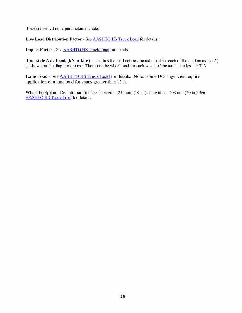
User controlled input parameters include:
Live Load Distribution Factor - See AASHTO HS Truck Load for details.
Impact Factor - See AASHTO HS Truck Load for details.
Interstate Axle Load, (kN or kips) - specifies the load defines the axle load for each of the tandem axles (A) as shown on the diagrams above. Therefore the wheel load for each wheel of the tandem axles = 0.5*A Lane Load - See AASHTO HS Truck Load for details. Note: some DOT agencies require application of a lane load for spans greater than 15 ft.
Wheel Footprint - Default footprint size is length = 254 mm (10 in.) and width = 508 mm (20 in.) See AASHTO HS Truck Load for details.

29
Cooper E-Series Railroad Loading
In accordance with AREMA specifications, BOXCAR requires a minimum depth of fill (measured from the base of the rail to the top of the box culvert) of 1.5 ft when a railroad loading is specified.
For background information on live loads and live load factors such as live load distribution factor, tire footprint, impact and lane loads, see Live Loads, General. Information specific to Cooper railroad loading is presented here.
The Cooper E-series railroad loading configuration is shown below for SI and US Customary Units.
Cooper Magnitude is the locomotive axle weight as defined by AREMA Specifications kN (kips).
Distribution - Railroad loads are distributed through fill assuming that the track structure, consisting of rails and ties, distributes the axle load uniformly over a width of 2.59 m (8.5 ft) at the surface, and is distributed with LLDF = 1 for depths greater than zero. The live load distribution is calculated assuming and infinite long line of axles spaced at 1.52 m (5 ft), thus there is no longitudinal distribution of live load in the direction of travel with increasing depth of fill.

30
NOTE: when a Cooper live load is selected the LLDF will AUTOMATICALLY change to a User Specified Value = 1.0 (consistent with the AREMA code Section 16.4.3). Changing back to a truck load WILL NOT reset the LLDF. The user must update the LLDF manually as appropriate.
Impact - None of the culvert design codes (AASHTO Standard Code, AASHTO LRFD Code or CHBDC Code) contain provisions for impact on a railroad loading. Therefore, if the "Design Code" option is selected for impact with a Cooper Railroad Load, BOXCAR will automatically compute the impact factor in accordance with the AREMA code Section 8.16.4.4. This is reflected on the output where the Live Load parameters are listed, impact will say "per AREMA Code". The value of the impact factor is printed above the live load table in a detailed output.
AREMA impact for box sections varies linearly from 1.6 at a depth of 0.46 m (1.5 ft) to 1.0 at a depth of 3 m (10 ft). The calculation is:
I = 1 + 0.6 * (10 - H) / (10 - 1.5) > = 1.0
where H is the depth of fill between the top of the box culvert and the base of the rails in ft.
The user still has the option to input the impact factor as a User Specified value.
31
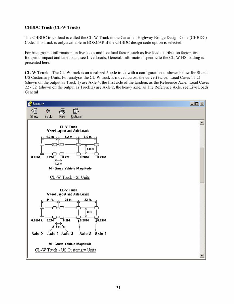
CHBDC Truck (CL-W Truck)
The CHBDC truck load is called the CL-W Truck in the Canadian Highway Bridge Design Code (CHBDC) Code. This truck is only available in BOXCAR if the CHBDC design code option is selected.
For background information on live loads and live load factors such as live load distribution factor, tire footprint, impact and lane loads, see Live Loads, General. Information specific to the CL-W HS loading is presented here.
CL-W Truck - The CL-W truck is an idealized 5-axle truck with a configuration as shown below for SI and US Customary Units. For analysis the CL-W truck is moved across the culvert twice. Load Cases 11-21 (shown on the output as Truck 1) use Axle 4, the first axle of the tandem, as the Reference Axle. Load Cases 22 - 32 (shown on the output as Truck 2) use Axle 2, the heavy axle, as The Reference Axle. see Live Loads, General

32
CL-W Truck - Ontario option
The Canadian province of Ontario uses a modified CL-W truck. The configuration of the truck is the same, but the axle load distribution differs from the standard code truck. The CL-W Ontario truck distribution is shown below for SI and US Customary Units. When the CL-W Truck is selected in BOXCAR, a radio button below the truck sketch allows the user to choose between the standard axle load distribution and the modified Ontario truck distribution..
CL-W Magnitude is the total truck gross vehicle weight, in kN (US tons). The axle load for each axle is equal to the specified gross vehicle weight multiplied by the coefficient shown on the figure.
Live Loads, CAN/CSA S6-06 CHBDC Code - The CHBDC code requires the following input values.
Live Load Distribution Distribution, LLDF - For H > 0.6 m (2 ft), LLDF = 1.75
For H < 0.6 m (2 ft) - based on interpretation of the CHBDC code by the American Concrete Pipe Association (ACPA), BOXCAR uses the AASTHO LRFD strip width method for distribution of the wheel load perpendicular to the direction of travel. or spans < 3m. For span > 3.0m, the distribution width is fixed at 2.587m
Impact (Dynamic Load Allowance (DLA)) - The CHBDC code Clause 3.8.4.5.2 defines DLA factors that vary linearly with depth and are dependent on the specific axle of the CL-W Truck under consideration.

33
BOXCAR uses 30% multiplied by 1.0 at ground for load cases 11 to 21 (reference Axle 4 - tandem axle) and 40% multiplied by 1.0 at ground for load cases 22 to 32 (reference Axle 2 - single heavy axle) decreasing linearly to 0% at 2m (but multiplier is never less than .1, or 10%).

34
Tandem/Tridem - User Specified Vehicle with 6 axles
For background information on live loads and live load factors such as live load distribution factor, tire footprint, impact and lane loads, see Live Loads, General. Information specific to Cooper railroad loading is presented here. There are no initial default values for other live load The Tandem/Tridem option allows the user to specify a custom vehicle with a total of 6 axles as shown in the Figure. Axle load distribution and spacings are based on user inputs. The Wheel Base is the spacing between wheels on an axle and is common to all axles. For analysis the Tandem/Tridem truck is moved across the culvert twice. Load Cases 11-21 (shown on the output as Truck 1) use Axle 5, the first axle of the tandem, as the Reference Axle. Load Cases 22 - 32 (shown on the output as Truck 2) use Axle 2, the middle axle of the tridem, as The Reference Axle.
Caution - If the truck configuration specified by the user has defined a heavy axle as Axle 6 with a large spacing X1, then depending on the span, the axle load may not be applied to the structure. The user is advised to run an "Other" live load with a single heavy axle to determine if the heavy axle controls.
See Live Loads, General
Tandem/Tridem truck load configuration
Input Parameters
Gross Vehicle Magnitude - Total vehicle weight, kN (kips)
Load Fraction (P1, P2, P3) - fraction of the load applied to each axle group. These fraction should add to 1.0 for application of the full vehicle load.
Spacing (X1, X2) - distance between center lines of axle groups
Wheel Pitch (S1, S2) - distance between axles of a given axle group
Wheel Base - distance between wheels on each axle. Assumed to be the same for all axles.

35
The magnitude of the applied wheel load is equal to the Gross Vehicle Magnitude (M) multiplied by Load Fraction, (P1, P2, or P3) divided by the number of axles in the group divided by 2.
Other Live Load -- User Specified Live Load
Selecting the Other Live Load option the user may specify one, two, or four wheels and the spacing between the wheels.
Specifying two wheels is equivalent to an axle load, and specifying four wheels is equivalent to a tandem or two axle loads.
Number of Wheels - Allowable input values are 1, 2, and 4 wheels
Load Magnitude per Wheel - This input value is the load on EACH wheel Spacing Perpendicular to Span - Center to center spacing of wheels along the axis of the culvert Spacing Parallel to Span - Center to center spacing of wheels in the span direction.
For all codes the "Other" wheel load is applied at the surface. The user defines the contact area of each wheel at the surface using the Tire Footprint Length (parallel to span) and Tire Footprint Width (perpendicular to span) input values. This contact area is then distributed through the soil FOR ALL DEPTHS OF FILL and FOR ALL DESIGN CODES using the specified Live Load Distribution Factor.
The program checks for interaction between wheel footprints.
Impact is applied to the magnitude based on the selected design code.
Note: For "Other" live loads the Direction of Traffic is always Parallel to Span.

36
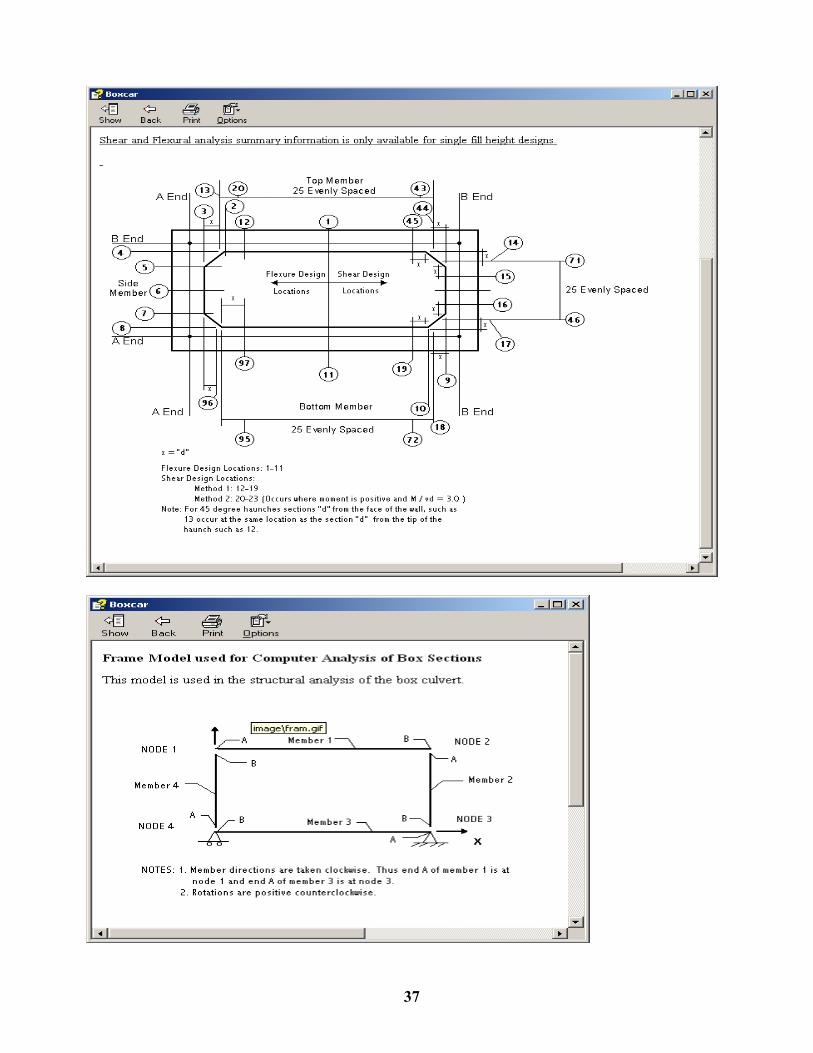
STRUCTURAL ANALYSIS
Moments, thrusts, and shears, are determined by the stiffness matrix method of analysis. Box culverts are idealized as 4 member frames with a one foot unit width. The computer model coordinate system, member and joint designations, and support conditions are shown graphically in the Frame Model Used for Computer Analysis of Box Sections. For a given frame, member stiffness matrices are assembled into a global stiffness matrix; a joint load matrix is assembled; and conventional methods of matrix analysis are employed. To reflect the stiffness of the haunch, flexibility coefficients for a member with linearly varying haunches are determined by numerical integration. The trapezoidal rule with 50 integration points is used and a sufficiently high degree of accuracy is obtained.
The moments, thrusts, and shears due to each load combination are determined and evaluated for each design section. There are a total of 97 design sections:
11 fixed design sections for the evaluation of flexural criteria;
12 fixed design sections for the evaluation of diagonal tension strength; and
25 evenly spaced design sections in each of the top slab, bottom slab, and sidewall as shown in the Location of Critical Sections.
Design forces are determined by factoring and summing the forces for each basic load case for each specified load combination and analyzing the resultant combined forces for the governing condition at each design section.
Design Sections
This figure depicts the location of design sections where BOXCAR evaluates limit states flexure and shear strength.
The table labeled "SUMMARY OF SHEAR ANALYSES OF SECTIONS" lists shear capacity/demand data for the typical controlling shear locations at a distance "d" from the face of the wall and "d" from the tip of the haunch for all members; top, bottom and sidewall and at each end of the member. Note if the culvert has 45 degree haunches the design sections for "d" from the face of the wall are set at "d" from the tip of the haunch. Additional design locations are considered in subsequent shear calculations, which check locations across the entire length of slabs and walls. Critical locations from the global shear check for each member are listed in the SHEAR DESIGN TABLE.
The FLEXURE DESIGN TABLE contains detailed information about the design sections at the controlling positive and negative moment conditions for the top slab, bottom slab, and sidewall. The table is ordered consistent with the standard ASTM reinforcing designations As1 through As8.
37

38
SOIL
Material Properties
Concrete Density - Unit weight of concrete, kN/m3, (lbs/ft3). The concrete density is used to compute loads due to culvert self weight. If designing box sections used as vertical shafts, the self weight does not contribute to moments, thus the concrete density may be set to a low value, such as 0.01.
Concrete Strength - compressive strength of concrete used for design, MPa (psi)
Main Reinforcement Type - this value is used to evaluate crack provisions for the CHBDC. (Clause 7.8.9.1)
Main Reinforcement Yield Strength - Yield strength of flexural reinforcement, parallel to the span of the culvert, MPa (ksi).
Soil Unit Weight - Unit weight of soil, kN/m3, (lb/ft3).
Stirrup Reinforcement Yield Strength – Developable yield strength of the stirrup reinforcement. The value input must reflect the strength of the stirrup anchorage, MPa (psi)
Design Coefficients and Factors
Application Code - Determines whether the vertical and lateral surcharge loads are treated as permanent dead load, additional dead load, or live load. See Dead Loads. and Live Loads, General.
Minimum Lateral Pressure Coefficient - Minimum fraction of vertical earth pressure acting as lateral pressure on the culvert sidewalls. Allowable range is 0 to 1. The minimum lateral pressure is assumed to be acting on the culvert at all times. The minimum pressure coefficient used to generate the standard designs in AASHTO M259 and M273 (ASTM C1433) is 0.25. The AREMA specified minimum lateral pressure coefficient is 0.4. See special note below for CHBDC designs. See Dead Loads.
Maximum Lateral Pressure Coefficient - Maximum fraction of vertical earth pressure acting as lateral pressure. on the culvert sidewalls. Allowable range is from the value input as the minimum lateral pressure coefficient to 9. Lateral pressure that is additional to the minimum lateral pressure specified above is considered additional dead load, and is only added into the design force at a particular design location if it increases the magnitude of the force. The maximum pressure coefficient used to generate the standard designs in AASHTO M259 and M273 (ASTM C 1433) is 0.50. The AREMA specified minimum lateral pressure coefficient is 1.0. See special note below for CHBDC designs. See Dead Loads.
Vertical Arching Factor (VAF)- Ratio of actual earth load on the box culvert to the soil prism load. Formerly called the soil structure interaction factor, Fe. Values may be computed by BOXCAR in accordance with AASHTO provisions or may be set by the user. See special note below for CHBDC designs. See Dead Loads.
AASHTO defines the VAF for embankment and trench installations. BOXCAR will calculate the VAF only for the embankment condition, but allows you to input alternate values for trench or other special design cases. VAF = 1 + 0.2 H/Bc where:

39
H = depth of fill over the culvert, m (ft)
Bc = outside span of culvert, m (ft)
VAF need not exceed 1.15 for installations with compacted fill at the side of the culvert, and need not exceed 1.4 for installations with uncompacted fill at the side of the culvert.
Special Note for CHBDC designs and Vertical and Horizontal Arching Factors for
Box Sections in Standard Installations
CHBDC Code Clause 7.8.4.2.3 specifies fixed values for the minimum and maximum Horizontal Arching Factors based on code specified Standard Installation Details. If the CHBDC is the specified design code and a standard installation is selected, BOXCAR will automatically set the Vertical Arching factor and a dialogue box will pop up and advises the user on the proper minimum and maximum lateral pressure coefficients. It is the user's responsibility to make sure that the proper values are input. A similar warning message pops up when a saved CHBDC design file with a standard installation is retrieved to input.
40
Default Configuration Utility
BOXCAR can be customized for easier use. The program is shipped with a two sets of default parameters, one for the SI system of units and one for Customary US Units. Minimum input required by the user is the file name, culvert span, culvert rise, and depth of fill above the culvert. After entering these values, BOXCAR fills in all remaining input fields from the default files.
Users may set the default file parameters to values that reflect the most common design values. This minimizes the number of fields that must be input for each design, and minimizes the risk of data entry errors. Default parameters can be set by selecting the option Reconfigure Default Parameters from the main menu.
The use of the default files are explained in the following help topics. Also provided are the initial values for the default files.
Default Screens Page 1.
Default Screens Page 2.
Default Screens Page 3.
Default Screens - Page 1
The first page of the default configuration screens has three purposes:
1. Select either the SI unit default file or the US customary unit default file for making changes. 2. Change the data directory where input and output files are stored. Warning - The data directory
must exist. BOXCAR will not operate properly if the data directory does not exist. 3. Begin changing default values.
Most input parameters are self explanatory.
Section length Slab, wall, and haunch dimensions - These parameters are input with simple equations which allow parameters to default to a ratio of the span, a fixed value, or a combination. For example, if the top slab thickness is set to default to Span/12 + 0, the top slab thickness of a 2.4 m (2400 mm) span culvert would default to 200 mm. Alternately, if the sidewall is set to default to Span/12 + 1, the sidewall of a 5 ft (60 in.) span culvert will default to 6 in. Two sets of equations are provided for the default thickness, as a function of the span. This allows default thickness to be set to the values in the standard precast box section designs contained in AASHTO M259 (ASTM C 1433).

41
Clear concrete cover reinforcement - For consistency with design code specifications, the default parameters allow different covers for the outside face of the top slab for depth of fill less than 0.6 m (2ft) and for depth of fill greater than or equal to 0.6 m (2 ft).
Main reinforcement yield strength
Design concrete strength
Concrete unit weight
Stirrup reinforcement developable yield stress - Note: The yield strength used for design of stirrups must reflect the capacity of the stirrup anchorage to develop the specified strength.
Total Service Stress Limit
Default Screens - Page 2
Default screen 2 sets values for most design parameters:
Design Code - Select if design methods should be in accordance with the AASHTO Standard Specifications for Highway Bridges (AASHTO Standard), the AASHTO LRFD Bridge Design Specifications (AASHTO LRFD), or the Canadian Highway Bridge Design Code (CHBDC). For additional information on the effect of this selection see Reinforcement Design:
Axial Thrust Load Factor - The design codes do not explicitly require a separate load factor for thrust affects. BOXCAR provides this factor in the event that the user wishes to de-emphasize or eliminate the effect of thrust. The factory defined condition is configured for a User Specified value of 1.0. If Design Code is specified than BOXCAR assigns default values of the tabulated Design Code Specified Load Factors. For the User Specified condition the specified value will be used for all loads.
Strength reduction / Material resistance factors - Strength reduction factors (AASHTO Standard) or resistance factors (AASHTO LRFD) are provided for flexure and shear strength.
Material Reduction factors for Steel and Concrete are provided for the CHBDC code.
Crack Width (CHBDC only) - This parameter sets the default value for the maximum crack width under service load conditions per CHBDC Clause 8.12.3.1. Permissible values are:
0.25 mm - (for non-prestressed components with potential exposure to de-icing chemicals; spray or surface runoff containing de-icing chemicals; marine spray; swamp; marsh; salt water; agressive backfill) and
0.35 mm - (for non-prestressed components subjected to other environmental exposures)

42
Reinforcement Diameters
Defaults for reinforcement diameter are a function of the thickness of the member in which they are placed:
Wire Diameter = x * member Thickness (in.) + y
The user may specify values for x and y. This allows the wire diameter to default to either a fraction of the wall thickness by specifying y = 0 or to an absolute diameter by specifying x = 0. The initial default values for these parameters are 0.05 times the wall thickness.
Maximum reinforcement spacing
Soil Unit Weight
Minimum lateral pressure coefficient
Maximum lateral pressure coefficient
Vertical Arching Factor (aka Soil Structure Interaction Factor)
Default Screen - Page 3
Live Load Data
Live load type - Users may default the live load type to any of the six live load options, or may default to no live load at all. The initial program default for english units is the AASHTO HS-Series Truck Load and the AASHTO Interstate/Tandem Truck Load. .The initial program default for SI units is the CHBDC CL-625 Truck Load. BOXCAR may allow more than one live load per run depending on the total number of wheels. Live load selections are automatically disabled for combinations that are not allowed. For each live load type, the user must specify other variables as well. For additional information on these variables, see the help topics for each live load type.
Default Values for AASHTO HS-series truck load
Default Values for AASHTO interstate (alternate military or design tandem) truck load
Default Values for Cooper E-series railroad load
Default Values for CHBDC Truck (CL-W Truck)
Default Values for Tandem/Tridem (user specified vehicle with 6 axles)
Default Values for Other which is a user specified load
43
Users may also select no live load as a default option.
Direction of Traffic
Impact Factor Options
Lane Load
Live Load Distribution Factor, LLDF
Fluid Loads
Depth of Fluid
Fluid Unit Weight
Surcharge Loads

44
REINFORCED CONCRETE DESIGN METHODOLOGY The reinforced concrete design methodology used in BOXCAR is presented as extracts from the AASHTO Standard Specifications, and the AASHTO LRFD Specifications, and the AREMA design specifications as appropriate. The original development of designs for precast box sections and verification of these designs is well documented, See the References. Flexure Design Service Load Flexural Requirements Shear Strength Requirements Shear Strength Requirements - AASHTO LRFD / CHBDC Stirrup Design
Design of Reinforcement for Flexure
Flexural reinforcement is designed for Ultimate Strength and Serviceability for negative moment and positive moment at all Design Sections except for sections specifically designated as Shear Design Sections (12 to 19). See Design Sections Figure and Reinforcement Layout Figure. Final reinforcing areas are selected based on the following:
(1) AS1 is based on the negative moment requirements in the side wall and in the outside face of the
top slab and bottom slab members where minimum steel is not sufficient.
(2) AS2 is based on maximum positive moment in the top slab.
(3) AS3 is based on maximum positive moment in the bottom slab.
(4) AS4 is based the maximum positive moment in the side wall.
(5) AS7 is based on negative moment at Section 1.
(6) AS8 is based on negative moment at Section 11.
AS1 is extended into the top and bottom slabs (Zmt and Zmb in Reinforcement Layout Figure) until the area
provided in AS7 or AS8, as appropriate, is adequate. BOXCAR assumes that minimum flexural steel is
provided for AS7 and AS8. Since BOXCAR does not select specific reinforcement bar sizes and does not
require a specific reinforcing layout, lap lengths (ld in Reinforcement Layout Figure) must be added by the
user. For many designs AS7 and AS8 provide adequate negative reinforcement for the entire top and/or bottom
slab, thus AS1 need only be extended into the slabs sufficiently to make a tension lap splice with AS7 or AS8
as required by AASHTO. The design summary sheet provides notes on the extension requirements for AS1.

45
Minimum flexural reinforcement is based on the AASHTO requirement for box sections of 0.002bh (Standard
Section 16.7.4.8, LRFD Section 12.11.4.3.2, and CHBDC Clause 7.8.11.1).
Maximum flexural reinforcement is based on limiting the flexural reinforcement to 0.75 of the balanced
reinforcement ratio. The design equation considers the decrease in the balanced ratio based on the presence of
axial compression. If maximum reinforcement governs, "REDES" is displayed as the controlling reinforcing
area and a warning message is printed, alerting the user that concrete compression governs, and the culvert
must be redesigned. Maximum reinforcing is calculated based on limiting the total strain the concrete to 0.003
in/in (mm/mm) for all codes.

46
Total Service Stress Limit - this value is the maximum allowable stress under service (unfactored) load conditions expressed as a percentage of the specified Main Reinforcement Yield Strength. When set to 100% there is no check for total service load stress. Note: For designs in accordance with the AASHTO Standard Code 8.16.8.4, the Total Service Stress Limit should be set to 60% Service Load Flexure Requirements for Crack Control BOXCAR checks to control cracking are dependent on the selected Design Code. AASHTO Standard Code Provisions to control cracking are based on AASHTO Standard Code 16.7.4.7 for precast box sections. fs = 98 / (dc A )0.33 where fs = service load steel stress dc = depth of concrete from extreme tension fiber to the center of the bar or wire located closest thereto. Clear
cover used to compute dc need not be taken greater than 50 mm (2 in.). A = area of concrete having the same centroid as the principle tensile reinforcement. Clear cover used to
compute this value nee d not be taken greater than 50 mm (2 in.). The provisions for crack control in cast-in-place concrete box sections are not evaluated. AASHTO LRFD Code Provisions to control cracking are based on AASHTO LRFD Code 5.7.3.4
s <= [700 γe / βs fss] - 2 dc
in which
βs = 1 + dc / 0.7 (h - dc ) where
γe = exposure factor ; BOXCAR assumes γe = 0.75 Class 2 exposure
dc = thickness of concrete cover measured from extreme tension fiber to center of the flexural reinforcement located closest thereto (in.)
fss = service load steel stress, ksi h = overall member thickness, in.

47
Canadian Highway Bridge Design Code (CHBDC) BOXCAR checks cracking based on Clauses7.8.9.1, 8.12.2, and 8.12.3 If the specified bar diameter <= 11.3 mm (0.445 in.) AND the Specified Maximum Spacing <= 100 mm (3.94) Then BOXCAR checks crack control per Clause 7.8.9.1 limit Fcr = 0.85
Crack-Control Coefficient, C1 depends on the type of reinforcement specified in the input. Welded Wire - C1 = 1.5 Deformed Bar - C1 = 1.9 Otherwise BOXCAR checks crack control per Clause 8.12 based on the specified "Crack Width" 0.25 mm - exposure to De-icing chemicals; spray or surface runoff containing de-icing chemicals marine spray; swamp; marsh; salt water; aggressive backfill 0.35 mm - Other environmental exposures Crack width, w = kb βc srm εsm where: kb = 1.0 βc = 1.7 srm = 50 + 0.25 * kc * db / rhoc kc = 1.0 db = the bar diameter calculated based on the required reinforcing area and specified spacing. Act = 2.5 * distance from the extreme tensile fiber to the centroid of the tensile reinforcement εsm = (fs / Esteel) * (1 - (fw / fs) ^ 2) Esteel = 200,000 MPa fw = stress in reinforcement at initial cracking (assuming cracking stress = 0.4 * fc) fs = stress in reinforcement at service load

48
Fatigue Stress Limits In accordance with provisions of the selected Design Code, BOXCAR limits live load stresses under some conditions to control fatigue. AASHTO Standard Code per Section 8.16.8.3 The range between a maximum tensile stress and minimum stress in straight reinforcement caused by live load plus impact at service load is limited by AASHTO to:
ff = 21 - 0.33 fmin + 8( r / h) where: ff = stress range, ksi fmin = algebraic minimum stress level, tension position, compression negative in kips per square inch r / h = ratio of base radius to height of rolled-on transverse deformations BOXCAR implements this conservatively by limiting the live load service stress to 21 ksi (145 MPa) AASHTO LRFD Code Based on Section 5.5.3.1 BOXCAR does not check the fatigue limit state if the AASHTO LRFD Code is the selected Design Code. Canadian Highway Bridge Design Code (CHBDC) In accordance with Clause 7.8.10, BOXCAR checks the Fatigue Limit State for fill heights < 0.6m (23.62 in.) The range between a maximum tensile stress and minimum stress is straight reinforced caused by live load plus impact at service load is limited by CHBDC Clause 8.5.3.1 to 125 MPa (18.13 ksi): BOXCAR implements this conservatively by limiting the live load service stress to 125 MPa (18.13 ksi).

49
Shear Strength Requirements AASHTO Standard Code Empirical top slab shear check: AASHTO Standard Specifications Article 3.24.4 States:" Slabs designed for bending moment in accordance with Article 3.24.3 shall be considered satisfactory in bond and shear." BOXCAR also enforces the provisions of Article 8.9.2 - Minimum slab thickness = (Span + 10)/30 > 0.542 ft. (Span in ft) or Minimum slab thickness = (Span + 3)/30 > 0.165 m (Span in m) and requires that the live load not be greater than an HS-25 truck, or 1.25 times the alternate military loading (interstate truck). If these conditions are met then shear is not check in the top slab and a text message is written to the output file stating that these provisions control.
if >φ Vc > Vu - no stirrups required

50
if Vu >φ Vc 1) program checks for Vu > Maximum allowable φ Vc, true - Stirrups are required. false - Program calculates additional flexural reinforcement required to eliminate stirrups. If Vu is less than the maximum permissible Vc, BOXCAR will calculate the required flexural steel to satisfy shear requirements without stirrups. This additional condition is evaluated separately and the alternate design is appended to the Shear Design Table section of the output. The design summary assumes that stirrups will be provided and it is left to the user to determine the applicability of the alternate design. If stirrups are required. the program automatically generates a Stirrup Design

51
Shear Strength Requirements AASHTO LRFD / CHBDC Design Codes Empirical top slab shear check (CHBDC design code): CHBDC CAN/CSA S6-06 Clause 7.8.8.2.2.1 states: For concrete box culverts the shear strength of the slab need not be checked if the following conditions are satisfied: a) center to center spacing of vertical walls is less than 4.0m b) the slab thickness is greater than 175mm (7 in.); and c) the reinforcement ratio of the bottom steel bars in the direction of the span is not less than 0.3%" BOXCAR also requires that the live load is not greater than a CL-625 truck, (or an AASHTO HS-series truck with a maximum axle load of 140 kN, or an AASHTO design tandem (interstate) truck with a maximum axle load of 110 kN)" If these conditions are met and shear is presumed adequate in the top slab. A message is printed to the output when this condition applies. AASHTO LRFD Code and CHBDC code, all members at all fill heights EXCEPT for AASHTO LRFD Code Slab members (top and bottom) with Fill Height >= 2 ft AASHTO 5.8.3.4.2 General Procedure and CHBDC 8.9.3.7 General Method Both codes use methods based on the Modified Compression Field Theory and specify empirical equations for determining the constants Beta and Theta. The user is directed to the referenced codes for details of the calculations. Note: the final design steel area resisting moment (AsDesign) is used for the calculation of Beta and Theta. Note that the AASHTO LRFD code includes limits (12 < sxe< 80) on the term sxe (12 < sxe< 80) that the CHBDC Code does not incorporate (the term is called sze in the CHBDC). The fundamental equation for shear resistance is Vc = 0.0316 * β * Sqrt(fc, ksi) * 12 * dv where dv, the effective shear depth = the greater of: (for the AASHTO LRFD Code per Section 5.8.2.9)
0.9 * d, 0.72 * h, or the distance between the resultants of the tensile and compressive forces due to flexure
(for the CHBDC Code per Clause 8.9.1.5) dv = the greater of
0.9 * d, or 0.72 * h

52
Lower limits on β are: β = 2.0 - AASHTO_LRFD Code 5.8.3.4.1 for sections not subjected to axial tension and having an overall depth < 16.0 in. β = per simplified method of CHBDC Clause 8.9.3.6 for sections not subjected to axial tension, provided the specified yield strength of the longitudinal reinforcement Fy <= 400 MPa (58.07 ksi), and the design concrete strength does not exceed fc <= 60 MPa (8.7 ksi) When the CHBDC design code is selected, BOXCAR also limits βmin = 3.0 for Fill heights > 0.6m consistent with the AASHTO Design codes. BOXCAR limits the concrete shear strength per CHBDC 8.9.3.4 based on fcr maximum = 3.2 MPa AASHTO LRFD Code with more than 0.6 m (2 ft) If the fill height is greater than 2 ft then shear strength in the top and bottom slabs is calculated in accordance with Section 5.14.5.3
where: Vc is in kips, f'c is in ksi, and the term (Vu d / Mu) is not taken greater than 1.0. As = the final design steel area resisting moment at the section. The strength computed by this equation is not taken less than 0.0948 * sqrt(f'c) or greater than 0.126 * sqrt(f'c) Note - This equation is the same as for AASHTO Standard Specifications only with differences in units: If the ultimate shear exceeds shear capacity of the concrete section, then BOXCAR performs the Stirrup Design as required.

53
Additionally, if Vu is less than the maximum permissible Vc, BOXCAR will calculate the required flexural steel to satisfy shear requirements without stirrups. This additional condition is evaluated separately and the alternate design is appended to the Shear Design Table section of the output. The design summary assumes that stirrups will be provided and it is left to the user to determine the applicability of the alternate design

54
RUNNING THE PROGRAM
Main Menu Options
After the introductory and user warning screens, the main menu appears and offers the following options: Create an SI Unit File
Create an English Unit File
Retrieve Input or Output File
Reconfigure Default Parameters
Delete Old Files
Exit Boxcar
1. Creating a File
A SI unit file and a Customary US unit file are created by the same procedure, as explained below.
You may obtain this help file at any time by clicking the ? box in the upper right hand corner of the
screen.
On Design Page 1, enter the filename, span, rise, and minimum depth of fill. Filling in the job
description field is optional.
To design a culvert for a single depth of fill, press enter without making an entry for maximum
depth of fill. BOXCAR will fill in all remaining variables with the default values, and will create a
scale image of the box culvert to be designed.
For designing for more than one depth of fill, enter a maximum depth of fill and depth increment. BOXCAR can complete designs for up to 45 depths of fill in a single run (However, output is limited when designs for multiple depths of fill are completed in a single run). After entering a depth increment and pressing the enter key, BOXCAR will fill in all of the remaining variables with the default values, and a scale drawing image of the box culvert to be designed will appear on the input screen.
You may then click the options button to execute the file, or review the input variables on the
remaining screens. You may customize the default values to values that you use most often by
selecting the Reconfigure Default Parameters option in the Main Menu.
Values on the input screens may be changed or accepted. Use the up/down arrows, the mouse or the enter key to move from field to field. Use the next page/previous page buttons on the input screen or the page up page down keys to move from screen to screen.

55
When all input variables have been set to the desired values, select the Options key, which brings up a menu with the following options:
Save Input & Execute Boxcar
Save Input & Return to Main Menu
Return to Main Menu Without Saving
Cancel
2. Retrieving Input or Output File
This option opens a window allowing you to recall input (.box) and output (.out) files. Input files may be modified and executed. Output files may be viewed and printed.
Additional output files created by Output Options 3 and 4 (*.csv and *.opt files) cannot be retrieved or viewed from within the BOXCAR program.
3. Default Configuration Utility
See Default parameters.
4. Deleting Old Files
This option allows you to delete input and output files that are no longer needed in memory. This task can also be performed through Windows Explorer.
5. Exit Boxcar
This option closes BOXCAR program windows and exits the program.
Clicking the x in the upper right hand corner of whatever window you have open will also exit the program. If you exit BOXCAR using the x option, the active input file will not be saved.

56
LIST OF REFERENCES
AASHTO (2002) "AASHTO Standard Specifications for Highway Bridges", American Association of State Highway and Transportation Officials, Seventeenth Edition, 2002 Washington, DC.
AASHTO (2007) "AASHTO LRFD Bridge Design Specifications," American Association of State Highway and Transportation Officials, Fourth Edition, Washington, DC.
AREMA, (2007) Manual for Railway Engineering, Chapter 8 Concrete Structures and Foundations, American Railway and Engineering and Maintenance-of-Way Association, Washington, DC, 2007.
CHBDC (2006), "National Standard of Canada CAN/CSA-S6-06 Canadian Highway Bridge Design Code", Canadian Standards Association, Mississauga, Ontario, Canada, 2006 Boring, M. R., Heger, F. J., and Bealey, M., 1974, "Test Program Evaluating Design Method and Standard Designs for Precast Concrete Box Sections with Welded Wire Fabric Reinforcing," Transportation Research Record, No. 518, Transportation Research Board, Washington, DC, 1974. Heger, F. J., and Long, K. N., "Structural Design of Precast Concrete Box Sectons to Support Surface Highway Wheel Loads with Zero to Deep Earth Covers," presented at ASTM Committee C-12 Symposium on Concrete Pipe, Chicago, IL, 1976. Heger, F.J., and McGrath, T., (1982) "Design Method for Reinforced Concrete Pipe and Box Sections," a report by Simpson Gumpertz & Hegr Inc for the American Concrete Pipe Association, December, 1982. LaTona, R. W., Heger, F. J., and Bealey, M., (1973) "Computerized Designs of Precast Reinforced Box Culverts," Highway Research Record, No 443, Highway Research Board, Washington, DC, 1973. McGrath, T. J., Heger, F. J., (1983) "Structural Design Manual for Improved Inlets and Culverts," Federal Highway Administration, Report No IP-83-6, June.


1” x 1”
25 FT. ROLLS1” x 2”
25 FT. ROLLSROUND 3/8” WALL
250 FT. ROLLS ROUND 1/2” WALL
250 FT. ROLLS
CLOSED-CELL
GASKET MATERIAL CELLULAR JOINT FILLER
What It Is
CLOSED CELL JOINT FILLER is a flexible, compressi-
ble material that easily fills difficult joints in concrete
pipes and structures. Whether glued onto the joint or
placed between the structures, it quickly conforms to the
joint profile. Closed Cell Joint Filler can be supplied as
cut and spliced gaskets, or as bulk material for field fabri-
cation of gaskets. It has excellent compressibility and is
resistant to weather, ozone, acids, and alkalis.
Why It’s BetterHow It Performs
CLOSED CELL JOINT FILLER MATERIALmeets or exceeds all requirements of:
ASTM D-1056 - Flexible Cellular Materials -Sponge or Expanded Rubber
Virginia and New York DOT approved.
Complies with NYDOT Std. 706.17
• Works with Round, Elliptical & Arch Pipe
• Works with Box Culverts and Manholes
• Available in 25’ or 250’ rolls, or by the foot
• Also available as cut and spliced gaskets
• Manufactured of high-quality synthetic rubber
• Easily compresses to fill irregular joints
• Clean and easy to use.
• May be used in place of trowelable sealants
• Easily cut and spliced in the field or in your yard
• May be glued directly to the joint
Typical Physical Properties
Color .....................................................Black
Compression Deflection (psi) ................5 - 9
Tensile Strength (psi Min.) ........................30
Elongation (%Min.) ................................ 125
Resilience - Bashore (% rebound Average)
(1/2” thickness @ 72ºF) .....................25 - 40
Shore 00 Durometer ..........................45 - 60
Density (pcf) average ......................5.5 - 7.5
Water Absorption by Weight (Max.).........10%
Temperature Range (F)
Low (Flex without cracking) .....................-70
High (Continuous) ...................................150
High (Intermittent) .................................. 200
Heat Aging (7 days @ 158ºF)
Lineal Shrinkage (Max.) .........................10%
Press-Seal believes all information is accurate as of its publication date. Information, specifications, and prices
are all subject to change without notice. Press-Seal is not responsible for any inadvertent errors. Copyright 2011.
83
Protecting Our Planet’s Clean Water SupplyPRESS-SEAL GASKET CORPORATION 800-348-7325 Fax (260) 436-1908
email: sales @press-seal.com
web: www.press-seal.comPress-Seal Gasket is an ISO 9001:2008 and ISO 14001:2004 Registered Company
RECTANGULAR CROSS-SECTIONS
are made from a Neoprene/EPDM Blend.
CIRCULAR TUBING CROSS-SECTIONSare made from a Nitrile/PVC blend.

1110/06
Threaded Splicing Systems
Thre
aded
S
plic
ing
Sys
tem
s
Dowel Bar Splicer System*ICC Evaluation Report No. 4028
The Dayton Superior Dowel Bar Splicer System is a two-piece, standard mechanical splicing technique (splicing bars of equal size) that eliminates protruding dowels. Typical applications include splicing reinforcement bars in monolithic struc-tures, rebar anchorages, future expansion, and dowel bar substitution at construction joints.
The components of the system, the Splicer and Dowel-In, are manufactured from standard grade 60 rebar material. Basic fabrication consists of forging and threading operations. No welding or machining is required and the threading operation does not reduce the nominal cross-sectional area of the bar. The completed splice (joined Splicer and Dowel-In) obtains ultimate bar strengths and meets or exceeds all existing code requirements including 160% fy or 95% of bar actual tensile requirements as identified by ICC acceptance criteria AC 133.
System AdvantagesThe patented Dowel Bar Splicer System has
been engineered, tested and proven to meet or exceed all field standards and design/ engineering practices. The Syst easy to use and readily identified as rebar material. The easy installation requires no special tools or machinery and simplifies the forming operations. There are no “extras,” such as wedges, nuts, collars or couplers required and routine cutting, bending, etc., can be easily handled in the field, if required.
The Dayton Superior Dowel Bar Splicer System Advantages:
• Strong• Safe• Easy to Use• Eliminates Protruding Dowels• Improves Forming Costs• Reduces Forming and Stripping Hassles• Saves Forms By Eliminating Drilling Holes• No Forming Required
System ComplianceThe Dowel Bar Splicer System complies with the following standards/specifications:
• International Conference of Building Officials (ICC Report #4028).• City of Los Angeles Research Report RR 24518.• American Concrete Institute (ACI Standard 318).• State Departments of Transportation.• Corps of Engineers (Specification CW03210).
Typical Splicing SpecificationThe Dayton Superior Dowel Bar Splicer System, consisting of the Dowel Bar Splicer and Dowel-In, shall be used in
splicing of rebar. The Dowel Bar Splicer shall be forged from ASTM A-615 grade 60 deformed rebar material, free of exter-nal welding and machining. It shall be furnished with an integral nailing flange and threaded with UNC or UN thread to a depth equal to the nominal thread diameter. The Dowel-In shall be fabricated from ASTM A-615 grade 60 deformed rebar material with thread corresponding to the Splicer. The completed splice shall meet 160% fy exceeding tensile requirements of American Concrete Institute Specification 318, Building Code Requirements for Reinforced Concrete and the Corps of Engineers Specification CW03210, Civil Works Construction Guide Specification for Steel Bars, Welded Steel Wire Fabric and Accessories for Concrete Reinforcement.
*U.S. Patent No. 4,619,096

14 10/06
Th
read
ed
Spl
icin
g S
yste
ms
Threaded Splicing Systems
Dowel Bar Splicer SystemD-101-A Straight Dowel Bar Splicer DB-SAE, D-102-A 90˚ Hooked Dowel Bar Splicer, D-103-A 180˚ Hooked Dowel Bar Splicer, D-104-A Double-Ended Dowel Bar Splicer
The Dayton Superior Dowel Bar Splicer is a one-piece unit, integrally forged from ASTM A615 grade 60 deformed rebar material. The splicers are available in #4 through #11 rebar sizes to be used in conjunction with the corresponding size dowel-in to accomplish a mechanical splice designed to achieve 160% of specified yield (full mechanical ultimate).
The splicer can be furnished straight (D-101-A) cut to length, 90˚ and 180˚ hooked (D-102-A and D-103-A) and double-ended (D-104-A) in plain or epoxy coated finish. The splicer can also be special-ordered with a reduced diameter washer flange or with the washer flange clipped (in more than one direction, if required) to provide adequate concrete cover, or to avoid interference.
The D-104-A Double-Ended Dowel Bar Splicer is used to establish a direct load path through a concrete section, thus avoiding multiple hooked rebar and eliminating rebar congestion. The double-ended unit can be configured in a “U” shape for special applications.
Clipped Flange
Nail Holes 1/2" Less
Than Flange
O.D.
Optional Clipped Flange
D-101-A Dowel Bar Splicer
C Dia. D Dia.Min
A
Length As Specified
Rebar Size
Smooth Transition (Approx. 1/2" Fillet Radius)
.250 Typ.
E +0.125
-0.000
B±.063
Note: No. 4, 5 and 6 splic-ers, 18", 24" and 36" long will usually have a stamped metal plug to protect threads; all other sizes will have a plastic cap plug.
*Loads shown based on 160% fy specified
#4 [#13] 5/8"–11 UNC 1/8"
#5 [#16] 3/4"–10 UNC 1/8"
#6 [#19] 7/8"–9 UNC 1/8"
#7 [#22] 1"–8 UNC 1/8"
#8 [#25] 1-1/8"–8 UN 1/8"
#9 [#29] 1-1/4"–8 UN 1/8"
BarSize
ThreadSize
B
#10 [#32] 1-7/16"–8 UN 1/8"
#11 [#36] 1-9/16–8 UN 1/8"
1-1/8"
1-9/16"
1-11/16"
1-27/32"
2-1/16"
2-3/16"
A
2-7/16"
2-9/16"
11/16"
13/16"
15/16"
1-1/16"
1-3/16"
1-5/16"
C
1-1/2"
1-5/8"
55/64"
1-3/64"
1-15/64"
1-27/64"
1-19/32"
1-25/32"
D
2"
2-7/32"
1"
1-1/8"
1-1/4"
1-3/8"
1-1/2"
1-5/8"
E
1-13/16"
1-15/16"
1-7/8"
2-1/16"
2-1/4"
2-7/16"
2-5/8"
2-13/16"
FlangeDiameter
3"
3-1/4"
Minimum Pult Range = 95% Fu Actual or 160%
Fy Specified*
19,200 lbs.
29,760 lbs.
42,400 lbs.
57,600 lbs.
75,840 lbs.
96,000 lbs.
121,920 lbs.
149,760 lbs.
Flange Diameter ±1/8"
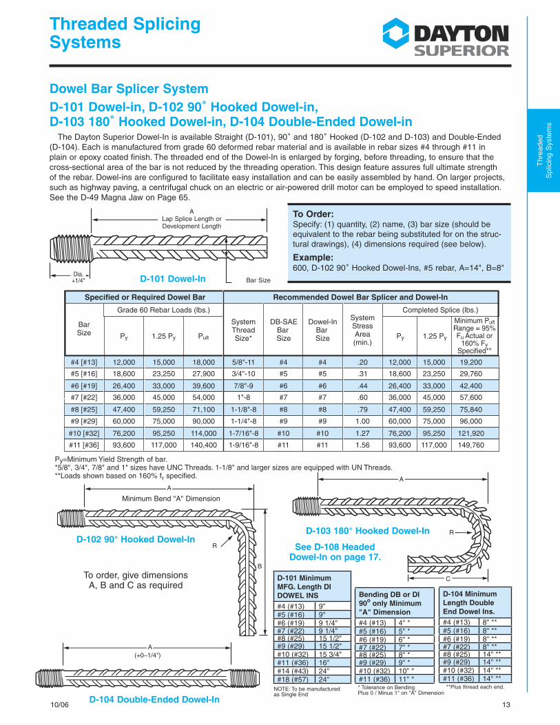
1310/06
Threaded Splicing Systems
Thre
aded
S
plic
ing
Sys
tem
s
Dowel Bar Splicer SystemD-101 Dowel-in, D-102 90˚ Hooked Dowel-in, D-103 180˚ Hooked Dowel-in, D-104 Double-Ended Dowel-in
The Dayton Superior Dowel-In is available Straight (D-101), 90˚ and 180˚ Hooked (D-102 and D-103) and Double-Ended (D-104). Each is manufactured from grade 60 deformed rebar material and is available in rebar sizes #4 through #11 in plain or epoxy coated finish. The threaded end of the Dowel-In is enlarged by forging, before threading, to ensure that the cross-sectional area of the bar is not reduced by the threading operation. This design feature assures full ultimate strength of the rebar. Dowel-ins are configured to facilitate easy installation and can be easily assembled by hand. On larger projects, such as highway paving, a centrifugal chuck on an electric or air-powered drill motor can be employed to speed installation. See the D-49 Magna Jaw on Page 65.
See D-108 HeadedDowel-In on page 17.
To Order:Specify: (1) quantity, (2) name, (3) bar size (should be equivalent to the rebar being substituted for on the struc-tural drawings), (4) dimensions required (see below).
Example:600, D-102 90˚ Hooked Dowel-Ins, #5 rebar, A=14", B=8"
AA
C
R
R
B
A(+0–1/4")
D-102 90˚ Hooked Dowel-In
To order, give dimensions A, B and C as required
D-103 180˚ Hooked Dowel-In
D-104 Double-Ended Dowel-In
Bar SizeD-101 Dowel-In
Py=Minimum Yield Strength of bar. *5/8", 3/4", 7/8" and 1" sizes have UNC Threads. 1-1/8" and larger sizes are equipped with UN Threads.**Loads shown based on 160% fy specified.
ALap Splice Length or Development Length
Dia. +1/4"
Specified or Required Dowel Bar Recommended Dowel Bar Splicer and Dowel-In
#4 [#13]
BarSize
SystemThreadSize*
DB-SAEBar Size
Dowel-In Bar Size
SystemStressArea(min.)
#5 [#16]
#6 [#19]
#7 [#22]
#8 [#25]
#9 [#29]
#11 [#36]
#10 [#32]
12,000
18,600
26,400
36,000
47,400
60,000
93,600
76,200
15,000
23,250
33,000
45,000
59,250
75,000
117,000
95,250
18,000
27,900
39,600
54,000
71,100
90,000
140,400
114,000
5/8"-11
3/4"-10
7/8"-9
1"-8
1-1/8"-8
1-1/4"-8
1-9/16"-8
1-7/16"-8
#4
#5
#6
#7
#8
#9
#11
#10
#4
#5
#6
#7
#8
#9
#11
#10
.20
.31
.44
.60
.79
1.00
1.56
1.27
12,000
18,600
26,400
36,000
47,400
60,000
93,600
76,200
15,000
23,250
33,000
45,000
59,250
75,000
117,000
95,250
19,200
29,760
42,400
57,600
75,840
96,000
149,760
121,920
Py 1.25 Py Pult Py 1.25 Py
Minimum PultRange = 95%Fu Actual or
160% FySpecified**
Grade 60 Rebar Loads (lbs.) Completed Splice (lbs.)
**Plus thread each end.
Minimum Bend "A" Dimension
Bending DB or DI 90o only Minimum "A" Dimension#4 (#13) 4" *#5 (#16) 5" *#6 (#19) 6" *#7 (#22) 7" *#8 (#25) 8" *#9 (#29) 9" *#10 (#32) 10" *#11 (#36) 11" *
D-104 Minimum Length Double End Dowel Ins.#4 (#13) 8" **#5 (#16) 8" **#6 (#19) 8" **#7 (#22) 8" **#8 (#25) 14" **#9 (#29) 14" **#10 (#32) 14" **#11 (#36) 14" **
* Tolerance on Bending Plus 0 / Minus 1" on "A" Dimension
D-101 Minimum MFG. Length DI DOWEL INS#4 (#13) 9"#5 (#16) 9"#6 (#19) 9 1/4"#7 (#22) 9 1/4"#8 (#25) 15 1/2"#9 (#29) 15 1/2"#10 (#32) 15 3/4"#11 (#36) 16"#14 (#43) 24"#18 (#57) 24"
NOTE: To be manufactured as Single End

T-WALL® Retaining Wall System
CONSTRUCTION MANUAL
Ph.: 703-913-7858Fax: 703-913-7859 www.neelco.com
THE NEEL COMPANY8328-D Traford Lane Springfield, VA 22152

© 2007 The Neel Company The T-WALL® Retaining Wall System is Patented
CONSTRUCTION MaNUal
CoNTeNTSPart I EARTHWORk ......................................................................................................... 1 • The STRuCTuRe DePeNDS oN iT!
Part II GENERAL OvERvIEW ........................................................................................ 2 • Work to be Performed by the Contractor ............................................... 2 • Basic Construction Procedures .................................................................. 2 • Crew Size and Production Rates ................................................................ 2 • Materials & Services supplied by The Neel Company and/or the Licensed Producer ................................................................................... 2 • equipment, Materials and Tools Supplied by the Contractor ......... 2 Part III CONSTRUCTION PROCEdURES ............................................................... 3-8 • Site Preparation ............................................................................................... 3 • Leveling Pad Construction ........................................................................... 4 • T-WALL® unit Delivery .................................................................................... 5 • unloading the units ....................................................................................... 5 • Layout on the Leveling Pad ......................................................................... 6 • erection of the First Course ......................................................................... 6 • Constructing Subsequent Courses and Backfilling ........................ 7-8 • Staged Construction ...................................................................................... 9
Part Iv CONSTRUCTING BATTEREd WALLS .................................................. 10-11
Part v CONSTRUCTION dETAILS ......................................... 12 & iNSiDe BACk CoVeR
• Fences and Railings ......................................................................................12 • Barriers ..............................................................................................................12 • Guard Rail .........................................................................................................12 • Corners ..................................................................................... iNSiDe BACk CoVeR
• Pipe Penetrations and pipes behind walls .................. iNSiDe BACk CoVeR
V07.04
NOTE TO THE READERThis manual has been prepared as a guide to building T-WALL® Retaining Wall structures. Its contents should be thoroughly reviewed by the contractor and the superintendent responsible for construction prior to the delivery of the T-WALL® units to the job site. The Neel Company and/or its Licensed Producers will provide job site techni-cal assistance to help the contractor implement correct construction procedures. Compliance with this manual does not relieve the Contractor of the responsibility to adhere to contract plans and specifications. The T-WALL® Retaining Wall System should never be built without drawings stamped by a Professional Engineer.
Copies of the T-WALL® Construction Manual can be downloaded from www.neelco.com
T-Wall® Retaining Wall System

EARTHWORK– THE STRUCTURE DEPENDS ON IT! PARTI
• FOundATIOn – The foundation should be inspected and approved by the owner’s engineer before the leveling pad is poured. if the foundation is soft, the wall will settle.
• SElEcTbAcKFIllgRAdATIOn – This is critical to the structure’s stability. See the T-WALL® shop drawings for project backfill gradation. it is important that gradation tests be performed through- out construction to ensure that the backfill meets the specifications. The select backfill gradation affects the friction on the stems, drainage and settlement.
• cOmPAcTIOn – Proper compaction of the backfill between and behind the stems is required to prevent settlement which will affect paving at the top of the wall.
Thefollowingearthworkitemsareveryimportant:
SINGLE UNITWEIGHT(#)
T-WALL® UNIT WEIGHTS
468
101214161820
160018502100235026002900315034003650
STEMLENGTH (ft)
DOUBLE UNITWEIGHT(#)
320037004200470052005800630068007300
Single Unit double Unit
Specifications are printed on the T-WALL® shop drawings, failure to meet the specifications of any of the above items may result in wall movement.
1
The concrete T-WALL® units are only half of the structure; the earthis the other half. This combination makes the wall stand up.

• WORKTObEPERFORmEdbYTHEcOnTRAcTOR: • Site preparation, including excavation • Forming and pouring the leveling pad • Wall construction including backfilling • installation of fences, guardrails or other necessary items
• cREWSIZE: • A typical wall erection crew includes: • one operator for excavator/crane for setting units & backfill placement • one working foreman to check alignment • Two men for setting units and placing joint materials • one front-end loader and operator to deliver backfill and T-WALL® units • PROducTIOnRATES: • Construction rates for T-WALL® depend entirely upon the rate at which select backfill can be delivered, placed and compacted.
2
PARTIIgEnERAlOVERVIEW
•bASIccOnSTRucTIOnPROcEduRES: • Form and pour leveling pad • Set first course of units • Place and compact select backfill • Place joint material and shear keys • Set second course of units
•mATERIAlSAndSERVIcESSuPPlIEdbYTHEnEElcOmPAnYAnd/ORTHElIcEnSEdPROducER: • Sublicense to build the structure • on-site technical assistance • engineering and design of the structure • Delivery of the following wall materials to the site: • Precast concrete T-WALL® units • Vertical filter fabric • Shear keys • Shear key wrap material • horizontal joint material • Connection hardware (when required by the design)
•EQuIPmEnT,mATERIAlSAndTOOlSSuPPlIEdbYcOnTRAcTOR: • T-WALL® unit lifting equipment: backhoe or small crane. • equipment for hauling, dumping and spreading backfill: dump trucks, front-end loaders and dozers. • Compaction equipment: small walk-behind vibratory roller or plate compactor • Tools: • Lifting device & rigging • Chalk line • Four-foot carpenter's level • Surveyor's level to check grade • Shims • Crow bars & pinch bars • Duct tape (for shear keys and filter cloth) • Broom to sweep leveling pad • Power drill (10" x 3/4" carbide bit for drilling bolt holes in corner units) • 3/8" rod for gauging vertical joints

• excavate the site to the elevation shown on the contract plans for the entire footprint of the T-WALL® structure (including the area covered by the select backfill between the stems). under special conditions, the excavation may be done in increments to minimize the amount of open cut.
• Proof roll the foundation in accordance with the project specifications.
• All unsuitable materials below subgrade must be removed and replaced with select, compacted backfill at the direction of the owner's engineer.
• Foundation is to be inspected and approved by the owner/ owner’s engineer for required bearing capacity as shown on the approved T-WALL® drawings.
• Where possible the width of excavation should allow sufficient room to set the longest stem with some space behind the stem to access the space between the stems.
• excavate for the leveling pad.
• Any under-drains, drainage piping or drainage blankets should be installed at this time.
cOnSTRucTIOnPROcEduRESPARTIII
SITE PREPaRaTION:
3
Preparing the site
Typical Vertical T-WALL® Section

4
PARTIIIcOnSTRucTIOnPROcEduRES(continued):
STEPPEdlEVElIngPAd:
• Steps in the Leveling Pad - Construct the lower leveling pad. Leave a 6 to 8" gap before constructing the higher pad. This gap will assure that the higher pad does not interfere with the placement of the units on the lower pad.
Stepped leveling pad
lEVElING PaD CONSTRUCTION:
• The leveling pad is usually 12 inches wide and a minimum of 6 inches deep.
• For a vertical wall: the typical step (change in elevation) is - 2'-6 1/2" for standard units, or 5'-1" for double height units.
• Pour the leveling pad. The concrete surface fin- ish must be smooth and flat.
• Check the leveling pad for line, grade and toler- ance with a level. if the leveling pad is out of tolerance, make correc- tions at this time.
• Check for alignment. The front edge of the pad should be 3" outside the front face line of the wall.
• The leveling pad is for construction alignment only; the concrete may be low strength, 2,500 psi and there is no rebar in the leveling pad.
• Form the leveling pad similar to forming a side- walk. The edge forms are the screed rail. They must be checked with a level to assure proper elevation and tolerance. Finish sur- face tolerance is 1/4 inch in any 10 foot length.

5
• under normal circumstances, a two hour unload- ing time is allowed for each delivery. During this period of time, the units may be unloaded and stacked on the ground. if the time allows, the units may be placed directly into the wall structure.
• Care must be exercised during handling to pro- tect the units and joint materials from damage. Do not stack units more than two high.
• Dunnage and plastic edge guards are the prop- erty of the Precast Manufacturer and must be collected and returned as soon as possible.
• if the units are precast with lifting inserts the Contractor will provide his own lifting devices. The lifting devices are to be compatible with the lifting inserts specified in the approved shop drawings.
• if the units are precast without lifting inserts the Contractor may be loaned, upon agreement, a lifting device. • The lifting device must be kept in good working order for safe lifting. • if the device has excessive wear or broken parts, Do NoT uSe. Contact the licensed precaster and/or The Neel Company for a replacement device. • if the device is lost, damaged or stolen the Contractor will be responsible for the cost of the device.
Unloading units from truck
Lifting a 10' unit at the balance point
(continued) cOnSTRucTIOnPROcEduRESPARTIII
• Prior to the start of construction, the Contrac- tor and The Neel Company or the Precast Man- facturer should develop a schedule for material deliveries. This timetable will allow the producer to match unit production with the construction schedule.
T-Wall® UNIT DElIVERY:
UNlOaDING THE UNITS:
Lifting a double unit which was precast with lifting inserts
LIfTING THE UNITS:

6
First course of units on leveling pad
Second course / joint material
Putting units into position
• Always begin erection at a fixed point such as a corner, step, or tie-in to an existing structure. if there is no fixed point, simply start on the lowest leveling pad. use a gauge to hold the 3/8" verti- cal space between units. A smooth 3/8" steel rod 18" long works best.
• Joint material is not required between the level- ing pad and the precast units.
• Set the first units on the leveling pad, using the chalk line as a guide for aligning the front face.
• Adjust the elevation of the back of the stem to plumb the front face of the unit.
• After aligning the front face, check the top of the front face for level and height with relation to the other units in this course. if the top of the unit is irregular, place the level on the line where the top of the front face is chamfered. Shim as necessary. Rechecking alignment, level and plumb to make sure that you have not disturbed one while adjusting the other.
• Finally, step back and sight down the tops of the units. This visual check will allow you to fine tune the alignment.
• every effort should be made to ensure that the first course of units is properly aligned and level.
• Construct the wall in horizontal lifts.
• To establish wall alignment, snap a chalk line on the surface of the leveling pad about 3" back from the front of the pad. This will be the front face of the wall and will center the unit on the leveling pad.
• Grade and compact the subgrade material level with the top of the pad the full length of the stems so that the front face of the units will be plumb. After a unit is set, it is much easier to shim the stem up than to excavate down; therefore it is better to be low than high in this operation.
laYOUT ON THE lEVElING PaD:
ERECTION OF THE FIRST COURSE:
PaRT III CONSTRUCTION PROCEDURES (continued)
WALLS hAve A Tendency To groW or Shrink in LengTh depending on The AmounT of cAre TAken To properLy LAyouT And ALign The firST courSe!
(continued)cOnSTRucTIOnPROcEduRESPARTIII

Filter fabric covering vertical joints on back face
(continued)cOnSTRucTIOnPROcEduRESPARTIII
• The number of keys required per unit is shown in the actual section(s) on the T-WALL® drawings for the project.
• The purpose of the shear keys is to: –provide an alignment guide –prevent movement of the unit during backfill and compaction –provide additional pullout resistance at the top of the wall.
• it may be necessary to plumb the units using shims between the stems at the back of the units. Shims may be pieces of standard asphalt shingles, plastic or wood.
• if you encounter a unit that is out of square it is best to use the face as a guide to alignment. keep in mind that this is purely an aesthetic concern, not a structural problem. however, difficulties with plumbing and alignment should be reported to The Neel Company.
• Dump the select granular backfill material direct- ly on top of the stems. This procedure will fill both sides equally and prevent lateral movement of the unit. It is mandatory that the backfill material meets the gradation specification shown on the project drawings.
7
Shear keys in shear key wrap
Filter fabric placement
• Prior to initial backfilling, the 12" wide filter fabric should be cut into lengths equal to the height of the wall at each vertical joint. Center these strips across the 3/8" vertical joints between the units at the rear face. This procedure prevents the migration of the backfill material through the joint.
• Throw the excess filter fabric over the top of the units during backfilling and pull it back on the backfill during setting operations.
• horizontal joint material is placed in the horizontal joints between the units at the face. This material acts as a cushion to pre- vent concrete-to-concrete contact and as a gasket to prevent backfill material leakage. Position the horizontal joint material so that it is flush with the rear face of the unit.
• Shear keys, wrapped twice with the provided shear key wrap, should be placed in the space between teeth where the top and bottom stems come together.
CONSTRUCTING SUBSEQUENT COURSES aND BaCKFIllING:
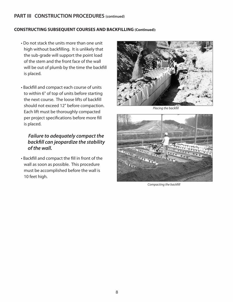
8
• Do not stack the units more than one unit high without backfilling. it is unlikely that the sub-grade will support the point load of the stem and the front face of the wall will be out of plumb by the time the backfill is placed.
• Backfill and compact each course of units to within 6" of top of units before starting the next course. The loose lifts of backfill should not exceed 12" before compaction. each lift must be thoroughly compacted per project specifications before more fill is placed.
Failure to adequately compact the backfill can jeopardize the stability of the wall.
• Backfill and compact the fill in front of the wall as soon as possible. This procedure must be accomplished before the wall is 10 feet high.
PARTIIIcOnSTRucTIOnPROcEduRES(continued)
Placing the backfill
Compacting the backfill
CONSTRUCTING SUBSEQUENT COURSES aND BaCKFIllING (Continued):

STaGED CONSTRUCTION:
• T-WALL® should be constructed horizontally, one course at a time.
however, there are some situations where staged construction may be necessary.
• Be aware that if the vertical height differ- ence between adjacent columns is greater than one unit, the vertical joints will open due to the unbalanced earth pressure.
9
(continued)cOnSTRucTIOnPROcEduRESPARTIII
In order to avoid problems with the wall alignment, you must contact The Neel Company for specific instructions whenplanning for staged construction.

• Fabricate this template out of 2x6 lumber.• The top is 5’ 3/8” long.• The stem is equal to the longest stem used in the bottom row of units.• The template stem can be shortened as the work progresses from longer to shorter stemmed T-WALL® units.
• Fabricate a wood wedge of dimensions equal to the wall batter. • A 1:6 batter will result in a wedge 48” x 8”. • Attach the wedge to a 4’ long carpenter’s level.
• The top of the leveling pad is not level across its width.• use the level-wedge tool to check the leveling pad form prior to placing concrete.• After the pad forms are stripped, use the level-wedge and T-template to check the subgrade slope behind the pad.
THE “T”-TEMPLATE
CONSTRUCTING BATTEREd WALLSTHE LEvEL-WEdGE
T-template
Batteredleveling pad THE BATTEREd LEvELING PAd
Cross-section of battered leveling pad
PARTIVcOnSTRucTIngbATTEREdWAllS
10
Level-wedge for checking wall batter of 1 to 6

Rigging and setting a T-WALL® unit
THE BATTEREd LEvELING PAd continued . . .
• use the level-wedge tool to check the vertical plumbness of each unit’s face as it is set.• The level-wedge can be used to check the top of the stem for proper set.• The level will read level when the design batter is achieved.• The leveling pad step does not line up vertically, but is off-set by the batter of the wall.• use the level-wedge to check step location prior to pouring concrete.
THE BATTEREd WALL
Checking the set of a battered unit
11
(continued)cOnSTRucTIngbATTEREdWAllSPARTIV
• The 2’-5 1/2” step dimension shown on the wall drawings is measured along the battered face of the wall.• There are no curves in a battered wall.• The wall must run straight from angle point to angle point.• A series of special tapered units will be provided to accommodate the change in wall direction at each angle point.• Adjust the shackle position on the lifting clamp or the sling lengths if using inserts to rig the units to hang in a tilted position equal to the wall batter. This greatly simplifies unit placement in the wall.
12
PARTVcOnSTRucTIOndETAIlSsee contract drawings for project specific details
Railing Detail
Guard Rail
Chain Link Fence
BaRRIERS
(example only - barrier types vary by project)

large Pipe Penetrations
Corner
see contract drawings for project specific details – cOnSTRucTIOndETAIlSPARTV
alternate Corner Detail: stems alternate by rows
angle Point
Detail
Pipe Parallel to Wall Face

T-WALL® Retaining Wall System
Construction Manual
The Neel Company8328 Traford Lane Ste. DSpringfield, VA 22152
703-913-7858 ph.703-913-7859 fax
www.neelco.com


![[@IndeedEng] Boxcar: A self-balancing distributed services protocol](https://static.fdocuments.in/doc/165x107/5562d5b6d8b42a49398b4f84/indeedeng-boxcar-a-self-balancing-distributed-services-protocol.jpg)


