Bourn & Koch Machine Catalog
74
MACHINE TOOLS AND SERVICES
Transcript of Bourn & Koch Machine Catalog

MACHINE TOOLSAND SERVICES

STAR SU LLC5200 Prairie Stone Parkway, Suite 100
TEL: 847-649-1450 FAX: 847-649-0112 Email: [email protected]
Regional Sales ManagersNortheast – Bob Allen ME, VT, CT, Eastern NY, NJ, MD, DE, NH, MA 802-296-1124 [email protected]
Southeast – Rodney Howard VA, WV, NC, SC, GA, FL, AL 704-907-3892 [email protected]
Ohio Valley – Ray Frey OH, Western KY, Western PA 248-885-5320 [email protected]
Michigan – John Simpson MI, GM Toledo, ON 248-766-7456 [email protected]
Indiana – Brad Wilson South & Central IN, KY, Toyota (WV) 765-744-4780 [email protected]
Mid-Central – Fred Schomaker IL, IA, NE, Northern IN 630-399-0025 [email protected]
North Central – Steve Peterson WI, MN, ND, SD 847-287-0418 [email protected]
South Central – Russ Nagy, Sr. MO, KS, OK, AR, MS, LA, TX, Western TN 847-867-9758 [email protected]
West – Dennis Zastrow AZ, CA, NM, NV, OR, WA, ID, UT, MT, CO 949-433-3372 [email protected]
International – Call 847-649-1450 [email protected]
2

INTRODUCTION
3

STAR SU LLCStar SU LLC is a selling cooperative made up of the three (3) partner companies of:
Star Cut Sales, Inc., Farmington Hills, MI SU America, Inc., Hoffman Estates, IL, a unit of Samputensili SpA of Bologna, ItalyBourn & Koch Inc., Rockford, IL
Star SU is the go-to-market cooperative managed by a board made up of the senior management of the 3 partner companies. Its purpose is to reduce the cost of getting to the market by consolidating common Human Resource & Benefit administration, IT administration, direct selling personnel, advertising, exhibitions and marketing initiatives and sales and sales engineering management.
The consolidation results in a leaner, more cost effective go-to-market initiative than each company having its own duplicate sales, marketing, HR and IT departments.
Star SU is not a manufacturer’s representative. It is the direct sales organization for the 3 partnered companies. As a selling cooperative for the 3 partnered companies, Star SU has 42 direct sales people calling in North America.
STAR CUTTER COMPANY
Star Cutter Company was founded in 1927 by Howard B. Lawton and Frank Burgess. The company was started in a leased portion of a building on Epworth Boulevard in Detroit, Michigan. During its first year of operation, Star Cutter Company employed nine to ten employees. The main customers at the time were Chrysler and Chevrolet Gear and Axle. From this small beginning, Star Cutter Company has developed into a world leader in the cutting tool industry with eight manufacturing facilities within four manufacturing divisions, which produce seven product lines. Each manufacturing facility specializes in producing a specific type of product or service. This structure provides maximum product quality and control. Headquartered in Farmington Hills, Michigan, Star Cut Sales, Inc. is a wholly owned subsidiary of Star Cutter Company and provides the Michigan central office presence for Star Cutter management and Star SU’s selling team. This extended group is an international organization of marketing specialists, service technicians and direct salespeople augmented by manufacturer’s agents in the U.S., Canada, Mexico and throughout the world.
INTR
OD
UC
TION
4

BOURN & KOCH MACHINE TOOL COMPANY
Bourn & Koch Machine Tool Company has manufactured precision machine tool products since 1975, which included the purchase of the Barber-Colman line of gear manufacturing machines. The Rockford plant offers 130,000 square feet of working space and a staff of highly skilled engineers and technicians. Bourn & Koch manufactures new, rebuilds, remanufactures, retrofits and recontrols gear cutting machines, gear inspection machines, gear grinding machines, vertical grinding centers, rotary surface grinding machines, vertical spindle turning centers and multi-spindle screw machines.
SU AMERICA
SU America is a unit of Samputensili S.p.A., which is the machine tool unit of the Maccaferri Industrial Group, a multinational organization, which operates in various diverse fields around the world, employing over 3,200 people. Samputensili offers a complete range of gear manufacturing equipment and gear tools through three main business units, which focused on a specific field: machine tools, gear cutting tools and rotor technology. Combining the expertise of these three product lines means Samputensili can provide complete manufacturing solutions for various gear technology requirements in the automotive industry, the machine and power tool industry, construction, the mining industry, earth moving equipment manufacturers, hydraulic pump manufacturers, gearbox producers, elevator and crane manufacturers, aerospace, energy, shipbuilding and the medical industry. The company has production facilities in Italy, Germany, Brazil, France, USA, China and Korea and operates through numerous sales offices with representatives around the world.
SAMPU T E N S I L I
INTR
OD
UC
TION
5

Star SU LLC5200 Prairie Stone Parkway, Suite 100Hoffman Estates, IL 60192USATel.: 847 649 1450Fax: 847 649 [email protected]
INTR
OD
UC
TION
Star SU LLCSales Office Michigan23461 Industrial Park DriveFarmington Hills, MI 48335-2855USATel.: 248 474 8200Fax: 248 474 [email protected]
Bourn & Koch Inc.2500 Kishwaukee StreetRockford, IL 61104USATel.: 815 965 4013Fax: 815 965 [email protected]
Star Cutter Co.Elk Rapids EngineeringMachine Tool Technology210 Industrial Park Drive/P.O. Box 728Elk Rapids, MI 49629-0728 USATel.: 231 264 5661Fax.: 231 264 [email protected]
S
tarS
U_I
ntro
duct
ion_
6-18
-09
Star SU LLC, Hoffman Estates/Illinois
Tools Service CenterTools Manufacturing SiteTools Service Center – Planned
WWW.STAR-SU.COM
6

table of contents
Gear Shaping.................................................................... 9-24
Horizontal Hobbing.......................................................... 25-34
Rotary Surface Grinding.................................................. 35-52
Vertical Chucking............................................................ 53-58
ID/OD Grinding................................................................ 59-72
Vertical Turning................................................................ 73-74
7

8

WWW.STAR-SU.COM
1000VBSGear Shaping Machine
STANDARD MACHINE SPECIFICATIONS
The Bourn & Koch 1000VBS CNC Shaper is a four (4) axes CNC stroking gear shaper with a Siemens 840D control for shaping internal and external gears.
GE
AR
SHA
PIN
G
Technical Data - Capacities & Limits
Maximum Dia. Swing up to 430 mm off table 1000 mm
Maximum Dia. Swing above 430 mm off table 850 mm
Nominal PD, External 1000 mm
Nominal PD, Internal 915 mm
Maximum Face Width 200 mm
Maximum Module, Spur 8.5
Maximum Module, Helical 5
Maximum Helix Angle 45º
Worktable Diameter 800 mm
Maximum Load on Worktable 2000 Kg
Cutter Spindle Stroking Range 30-200 SPM
Cutter Spindle Diameter 127 mm
Stroking Spindle Motor Power 15 Kw
Height (approximate) 2240 mm
Length (approximate) 2090 mm
Width (approximate) 1410 mm
Weight (Approximate Net) 16,364 kg
Actual machine W-H-L and Weight depend on ordered confi guration. Technical data is subject to change without notice and may vary according to the workpiece geometry, the loading system and the workholding equipment supplied.
9

GE
AR
SHA
PIN
G
1000VBSCNC Gear Shaping Machine
Submit a QUICK QUOTE Request
Total Cost:Standard Equipment Total ($):
Optional Equipment Total ($):
TOTAL ($):
Standard EquipmentDescription
Heavy stress relieved steel weldment base
Heavy stress relieved steel weldment column
Cross slide
Vertical columns are heavy, one-piece weldment
Self contained integral torque motor for workspindle
Self contained integral torque motor for cutterspindle
Automatic CNC controlled lubrication of guide ways and ball screws
Siemens 840D CNC Control
Programming of strokes per minute
Programming of cutter infeed rate
Programming of cutter infeed rate & rotary feed
Automatic programmable stroke length
Programming of number of cuts
Programming of fi nish cut depth
Cutter auto top positioning
Synchronization of cutter and work spindle
Quick truing of cutter and work spindles during setup
HMI for programming in conversational language
Dry fl oor machine enclosure with sliding door
Leveling screws
Work Light
Paint: One standard Polane color
Documentation
CE compliant
ANSI and NFPA compliant
Manufactured in USA
Standard Equipment Total ($):
Optional EquipmentDescription Price ($)
Mist collector
Automatic magnetic chip conveyor
Manual quick change cutter mechanism
CNC controlled electronic guide
Remote hand held station
Hydraulically operated, retractable tailstock
Part clamping cylinder
Automatic enclosure door
Automatic programmable stroke position
Quick returning stroking mechanism
Cutter adapter 1.75”
Cutter adapter 1.25”
Workholding fi xturing
Gear shaper cutters
Optional Equipment Total ($):
Star SU LLC5200 Prairie Stone Parkway, Suite 100Hoffman Estates, IL 60192USATel.: 847 649 1450Fax: 847 649 [email protected]
10

WWW.STAR-SU.COM
HS650-200B&K Fellows CNC Hydrostroke™ Gearless Gear Shaper
STANDARD MACHINE SPECIFICATIONS
The Bourn & Koch Fellows HS650-200 Hydrostroke™ is a six (6) axis CNC hydraulic stroking gear shaper with variable quick return stroking, direct drive spindles, electronic indexing, elevating cutter spindle housing, Fanuc 30iB CNC touch screen control, for shaping internal and external gears.
Technical Data - Capacities & LimitsNominal PD (external) 650 mm
Nominal PD (internal) 635 mm
Maximum Module 12.7 mod
Maximum Face Width 200 mm
Worktable Diameter 690 mm
Cutter Spindle Stroking Range 20-500 spm
Cutter Spindle Diameter 120 mm
Maximum Part Swing Diameter 1000 mm
Cutter spindle slide travel 300 mm
Height (Approximate) 3125 mm
Length (Approximate) 5334 mm
Weight (Approximate Net) 17195 kg
Technical details subject to change without notice.
GE
AR
LESS G
EA
R SH
AP
ER
Z
Top of Worktable
Ø
X
V
Actual machine W-H-L and Weight depend on ordered confi guration. Technical data is subject to change without notice and may vary according to the workpiece geometry, the loading system and the workholding equipment supplied.
ø = Nominal Workpiece Diameter; X= Center Distance; V= Face Width Range;
Z = Axial Cutter Slide Position Above Table Top
11

Submit a QUICK QUOTE Request
Total Cost:Standard Equipment Total ($):
Optional Equipment Total ($):
TOTAL ($):
Standard EquipmentDescription
Base machine with GE Fanuc 30iB CNC control
Hydrostatic spur guide
Pendant mounted console, 15” color LCD touch screen
GFI Duplex outlet (120 VAC)
Manual pulse generator, inch/metric switchable
Storage for approx. 100 part programs
Diagnostics and error prevention
Function controls and keypads for direct entry of gear shaping data
Operator’s menu with cutter confi guration menu, part setup menu, on-line diagnostics, cycle counter, cycle timer
6 axis control using AC Servo Direct Drives:
Electronic index drive for synchronizing of cutter and work rotation
Stroking speed
Stroking position
Work spindle rotation
Cutter spindle rotation
Infeed speed and position
Stroke length
Adaptive process control for optimizing chip load
Automatic compensation of temperature dependent CD changes
Servo stroke positioning of cutter spindle
Selectable number of cuts
Programmable, multi-surface cutting capability
Programmable infeed and rotary feed
Oriented Stiffness Back-Off™, servo driven for taper and crown
Water cooled heat exchanger for direct drives (requires plant water)
Hydraulic system, free standing 100 gal. HPU
Lubrication system
Coolant system, chip basket, optional chip conveyor
Full machine enclosure
Paint: Sherwin Williams Swiss Dotted Off-White
Documentation
Work lamp, high intensity
Manufactured in USA
Standard Equipment Total ($)
Standard Equipment Total ($):
Optional EquipmentDescription Price ($)
Hydrostatic helical guide
Electronic door open and close
Quick change cutter mechanism
Automatic hydraulic through hole fi xture clamping unit
Automatic tool change mechanism for storage of up to (8) tools
Stand alone liquid chiller unit for cooling direct drives
Hydraulic work clamp cylinder assembly
48” discharge height magnetic chip conveyor (rear discharge)
CNC controlled cutter offset
Hydraulically operated, retractable tailstock
Workholding fi xturing
Gear shaper cutters
Training Programs
CE certifi cation for EU destinations
Optional Equipment Total ($):
GE
AR
LESS G
EA
R SH
AP
ER
Star SU LLC5200 Prairie Stone Parkway, Suite 100Hoffman Estates, IL 60192USATel.: 847 649 1450Fax: 847 649 [email protected]
BOURN & KOCH INC.2500 Kishwaukee StreetRockford, IL 61104USATel.: 815-965-4013Fax [email protected]
HS650-200B&K Fellows CNC Hydrostroke™ Gearless Gear Shaper
12

WWW.STAR-SU.COM
HS1280-300B&K Fellows CNC Hydrostroke™ Gearless Gear Shaper
STANDARD MACHINE SPECIFICATIONS
The Bourn & Koch Fellows HS1280-300 Hydrostroke™ is a six (6) axis CNC hydraulic stroking gear shaper with variable quick return stroking, direct drive spindles, electronic indexing, elevating cutter spindle housing, and Fanuc 30iB CNC touch screen control for shaping internal and external gears.
Technical Data - Capacities & LimitsNominal PD (external) 1270 mm
Nominal PD (internal) 1270 mm
Maximum Module 12.7 mod
Maximum Face Width 300 mm
Maximum Stroke Length 380 mm
Worktable Diameter 1120 mm
Cutter Spindle Stroking Range 20-500 spm
Cutter Spindle Diameter 140 mm
Maximum Part Swing Diameter 1828 mm
Cutter spindle slide travel 300 mm
Width (Approximate) 3300 mm
Height (Approximate) 3550 mm
Length (Approximate) 5380 mm
Weight (Approximate) 31751 kg
Technical details subject to change without notice.
GE
AR
LESS G
EA
R SH
AP
ER
Z
Top of Worktable
Ø
X
V
Max.(mm)
Min.(mm)
Nominal work diameter
ø 1280 ~
Center distance X 868.2 0
Maximum work swing diameter
1828
Cutter spindel diameter (mm)
140 ~
Face width range V 300 ~
Stroke length 380 ~
Axial slide position (spindle face to table)
Z 924.8 250
Actual machine W-H-L and Weight depend on ordered confi guration. Technical data is subject to change without notice and may vary according to the workpiece geometry, the loading system and the workholding equipment supplied.
ø = Nominal Workpiece Diameter; X= Center Distance; V= Face Width Range; Z = Axial Cutter Slide Position Above Table Top
13

Submit a QUICK QUOTE Request
Total Cost:Standard Equipment Total ($):
Optional Equipment Total ($):
TOTAL ($):
Standard EquipmentDescription
Base machine with GE Fanuc 30iB CNC control
Hydrostatic spur guide
Pendant mounted console, 15” color LCD touch screen
GFI Duplex outlet (120 VAC)
Manual pulse generator, inch/metric switchable
Storage for approx. 100 part programs
Diagnostics and error prevention
Function controls and keypads for direct entry of gear shaping data
Operator’s menu with cutter confi guration menu, part setup menu, on-line diagnostics, cycle counter, cycle timer
6 axis control using AC Servo Direct Drives:
Electronic index drive for synchronizing of cutter and work rotation
Stroking speed
Stroking position
Work spindle rotation
Cutter spindle rotation
Infeed speed and position
Stroke length
Adaptive process control for optimizing chip load
Automatic compensation of temperature dependent CD changes
Servo stroke positioning of cutter spindle
Selectable number of cuts
Programmable, multi-surface cutting capability
Programmable infeed and rotary feed
Oriented Stiffness Back-Off™, servo driven for taper and crown
Water cooled heat exchanger for direct drives (requires plant water)
Hydraulic system, free standing 200 gal. HPU
Lubrication system
Coolant system, chip basket, optional chip conveyor
Full machine enclosure
Paint: Sherwin Williams Swiss Dotted Off-White
Documentation
Work lamp, high intensity
Manufactured in USA
Standard Equipment Total ($)
Standard Equipment Total ($):
Optional EquipmentDescription Price ($)
Hydrostatic helical guide
Electronic door open and close
Quick change cutter mechanism
Automatic hydraulic through hole fi xture clamping unit
Standalone liquid chiller unit for cooling direct drives
Hydraulic work clamp cylinder assembly
48” discharge height magnetic chip conveyor (rear discharge)
Workholding fi xturing
Gear shaper cutters
Training programs
CE certifi cation for EU destinations
Optional Equipment Total ($):
GE
AR
LESS G
EA
R SH
AP
ER
Star SU LLC5200 Prairie Stone Parkway, Suite 100Hoffman Estates, IL 60192USATel.: 847 649 1450Fax: 847 649 [email protected]
BOURN & KOCH INC.2500 Kishwaukee StreetRockford, IL 61104USATel.: 815-965-4013Fax [email protected]
HS1280-300B&K Fellows CNC Hydrostroke™ Gearless Gear Shaper
14

WWW.STAR-SU.COM
MS300-125B&K Fellows CNC Gear Shaper
STANDARD MACHINE SPECIFICATIONS
The Bourn & Koch Fellows MS300-125 is a seven (7) axis CNC mechanical stroking gear shaper with GE Fanuc 16i control, electronic indexing, and elevating cutter spindle housing for shaping internal and external gears.
Technical Data - Capacities & LimitsNominal PD (external) 305 mm
Nominal PD (internal) 305 mm
Maximum Module 6.35 mod
Maximum Face Width 125 mm
Maximum Helix Angle 45º
Worktable Diameter 350 mm
Cutter Spindle Stroking Range 50-2000 spm
Cutter Spindle Diameter 100 mm
Maximum Part Swing Diameter 527 mm
Cutter spindle slide travel 300 mm
Height (Approximate) 3100 mm
Length (Approximate) 3385 mm
Width (Approximate) 2176 mm
Weight (Approximate Net) 7030 kg
Technical details subject to change without notice.
GE
AR
SHA
PE
R
Z
Top of Worktable
Ø
X
V
Max. (mm) Min. (mm)
Nominal Work Diameter Ø 300 ~
Center Distance X
Maximum Work Swing Diameter (mm) 527 ~
Cutter Spindle Diameter (mm) 120 ~
Face Width Range V 125 0
Stroke Length 0
Axial Slide Position (spindle face to table) Z 575 275
Technical data subject to change without notice. Submit drawings for workspace interference study.
Actual machine W-H-L and Weight depend on ordered confi guration. Technical data is subject to change without notice and may vary according to the workpiece geometry, the loading system and the workholding equipment supplied.
ø = Nominal Workpiece Diameter; X= Center Distance; V= Face Width Range; Z = Axial Cutter Slide Position Above Table Top
15

Submit a QUICK QUOTE Request
Total Cost:Standard Equipment Total ($):
Optional Equipment Total ($):
TOTAL ($):
Standard EquipmentDescription
Base machine with GE Fanuc 16i CNC control
Hydrostatic spur guide
Quick change cutter system
Machine mounted console, 10” color LCD touch screen
Inch/metric inputs/outputs
Tool offsets
Manual pulse generator, inch/metric switchable
Diagnostics and error prevention
7 axis control using AC Servo Direct Drives:
Stroke drive
Rotary feed drive
Infeed drive
Electronic index drive
Cutter relief drive
Cutter elevate drive
Stroke length
Selectable number of cuts
Programmable, multi-surface cutting capability
Programmable infeed and rotary feed
Lubrication system
Coolant system 210 liter, chip basket, nested chip conveyor
Full machine enclosure
Paint: Sherwin Williams Swiss Dotted Off-White
Documentation
Work lamp, high intensity
Manufactured in USA
Standard Equipment Total ($):
Optional EquipmentDescription Price ($)
Hydrostatic helical guide
Quick change cutter adapter
Automatic hydraulic fi xture clamping unit
Hydraulically operated swing away center support
Power rear door, robot load ready
Continuous loop conveyor, pick and place automation
Workholding fi xturing
Gear shaper cutters
Training programs
CE certifi cation for EU destinations
Optional Equipment Total ($):
GE
AR
SHA
PE
R
Star SU LLC5200 Prairie Stone Parkway, Suite 100Hoffman Estates, IL 60192USATel.: 847 649 1450Fax: 847 649 [email protected]
BOURN & KOCH INC.2500 Kishwaukee StreetRockford, IL 61104USATel.: 815-965-4013Fax [email protected]
MS300-125B&K Fellows CNC Gear Shaper
16

WWW.STAR-SU.COM
MS650-125B&K Fellows CNC Gear Shaper
STANDARD MACHINE SPECIFICATIONS
The Bourn & Koch Fellows MS650-125 is a six (6) axes CNC mechanical stroking gear shaper with GE Fanuc 30i control, electronic indexing, elevating cutter spindle housing for shaping internal and external gears.
Technical Data - Capacities & LimitsNominal PD (external) 650 mm
Nominal PD (internal) 650 mm
Maximum Module 8.47 mod
Maximum Face Width 125 mm
Maximum Helix Angle 45˚
Worktable Diameter 690 mm
Cutter Spindle Stroking Range 20-500 spm
Cutter Spindle Diameter 120 mm
Maximum Part Swing Diameter 1000 mm
Cutter Spindle Slide travel 300 mm
Height (Approximate) 3125 mm
Length (Approximate) 5334 mm
Width (Approximate) 1989 mm
Weight (Approximate Net) 17195 kg
Technical data is subject to change without notice.
GE
AR
SHA
PE
R
Z
Top of Worktable
Ø
X
V
Max. (mm) Min. (mm)
Nominal Work Diameter Ø 650 ~
Center Distance X 585 -10
Maximum Work Swing Diameter (mm) 1000
Cutter Spindle Diameter (mm) 120 ~
Face Width Range V 125
Stroke Length 145 0
Axial Slide Position (spindle face to table) Z 565 275
Technical data subject to change without notice. Submit drawings for workspace interference study.
Actual machine W-H-L and Weight depend on ordered confi guration. Technical data is subject to change without notice and may vary according to the workpiece geometry, the loading system and the workholding equipment supplied.
ø = Nominal Workpiece DiameterX= Center Distance V= Face Width Range Z = Axial Cutter Slide Position Above Table Top
17

GE
AR
SHA
PE
R
Star SU LLC5200 Prairie Stone Parkway, Suite 100Hoffman Estates, IL 60192USATel.: 847 649 1450Fax: 847 649 [email protected]
BOURN & KOCH INC.2500 Kishwaukee StreetRockford, IL 61104USATel.: 815-965-4013Fax [email protected]
MS650-125B&K Fellows CNC Gear Shaper
Submit a QUICK QUOTE Request
Total Cost:Standard Equipment Total ($):
Optional Equipment Total ($):
TOTAL ($):
Standard EquipmentDescription
Base machine with GE Fanuc 30iB CNC control
Hydrostatic spur guide
GFI duplex outlet (120 V AC)
Machine mounted console, 15" color LCD touch screenInch/metric inputs/outputs
Storage for approx. 100 part programs
Manual pulse generator, inch/metric switchable
Diagnostics and error prevention
Operator's menu with cutter confi guration menu, part setup menu, on-line diagnostics, tool offsets, cycle counter, cycle timer
Operating timer, real-time clock, total power-on elapse
6 axes control using AC Servo Direct Drives:
Stroke drive
Rotary feed drive
Infeed drive
Electronic index drive
Cutter relief drive
Cutter elevate drive
Stroke length
Automatic compensation of temperature dependent center distance changes
Servo stroke position of cutter spindleProgrammable, multi-surface cutting capabilityProgrammable infeed and rotary feed
Oriented stiffness backoff, Servo driven
Heat exchanger for intergral motors
Automatic lubrication system
Coolant system 210 liter, chip basket, nested chip conveyor
Full machine enclosure
Paint: Sherwin Williams Swiss Dotted Off-White
Documentation
Work lamp, high intensity
Manufactured in USA
Standard Equipment Total ($):
Optional EquipmentDescription Price ($)
Mist collector
Automatic magnetic chip conveyor
Electronic door open and close
Remote handheld station
Quick change cutter mechanism
Automatic (hydraulic) thru hole clamping unit
CNC controlled electronic guide
CNC controlled cutter offset
CNC controlled crowning and taper
Liquid chiller unit for direct drives
Automatic tool change mechanism
Machine mounted near net sensor
Hydraulically operated, retractable tailstock
Spare parts kit
Workholding fi xturing
Gear shaper cutters
Training programs
CE certifi cation for EU destinations
Optional Equipment Total ($):
18

WWW.STAR-SU.COM
MS450-125B&K Fellows CNC Gearless Gear Shaper
STANDARD MACHINE SPECIFICATIONS
The MS450-125 is a six (6) axis CNC mechanical stroking gear shaper with direct drive spindles, electronic indexing, optional electronic helix setting, elevating cutter spindle housing, for shaping internal and external gears.
Technical Data - Capacities & LimitsNominal PD (external) 450 mm
Nominal PD (internal) 450 mm
Maximum Face Width 127 mm
Maximum DP, Spur 8.47 mod
Maximum DP, Helical 8.47 mod
Maximum Load on Worktable 900 kg
Cutter spindle stroking range 20-500 spm
Cutter spindle diameter 120 mm
Width (approx.) 1989 mm
Height (No rise block) 3124 mm
Weight (approx. net) 9000 kg
Technical data is subject to change without notice.
GE
AR
SHA
PIN
G
Z
Top of Worktable
Ø
X
V
Max. (mm) Min. (mm)
Nominal Work Diameter Ø 450 ~
Center Distance X 584 -10
Maximum Work Swing Diameter (mm) 1000
Cutter Spindle Diameter (mm) 120 ~
Face Width Range V 125
Stroke Length 145 0
Axial Slide Position (spindle face to table) Z 565 275
Technical data subject to change without notice. Submit drawings for workspace interference study.
19

Submit a QUICK QUOTE Request
Total Cost:Standard Equipment Total ($):
Optional Equipment Total ($):
TOTAL ($):
Standard EquipmentDescriptionBase machine with Fanuc 30iB CNC systemHydrostatic spur guidePendant mounted console with 15” color LCD touch screenGFI duplex outlet (120 V AC)Manual pulse generator, inch/metric switchableProgrammable tool and work offsetsStorage for approx. 100 part programsDiagnostics and error preventionFunction controls and keypads for online direct entry of gear shaping dataOperator’s menu with cutter confi guration menu, part setup menu, on-line diagnostics, cycle counter, cycle timerOperating timer, real time clock, total power-on elapse6 axis control use AC servo direct drives:
Electronic index drive for synchronization of cutter and work rotationStroking speedStroking positionWork spindle rotationCutter spindle rotationInfeed speed and positionStroke Length
Adaptive process control for optimizing chip loadAutomatic compensation of temperature dependent center distance changesServo stroke position of cutter spindleSelectable number of cutsProgrammable, multi-surface cutting capabilityProgrammable infeed and rotary feedOriented Stiffness Backoff, servo drivenHeat exchanger for integral motorsAutomatic Lubrication systemCoolant system, chip basket, optional chip conveyorFull machine enclosurePaint, Sherwin Williams Swiss Dotted Off-WhiteDocumentationWork lamp, high intensityManufactured in USA
Standard Equipment Total ($):
Optional EquipmentDescription Price ($)Mist collectorAutomatic magnetic chip conveyorElectronic door open and closeRemote handheld stationQuick change cutter mechanismCutter adaptersAutomatic (hydraulic) thru hole clamping unitCNC controlled electronic guideCNC controlled cutter offsetCNC controlled crowning and taperingLiquid chiller unit for coolant systemAir cooled heat exchangerAutomatic tool change mechanismMachine mounted near net sensorHydraulically operated, retractable tailstockSpare parts kitWorkholding fi xturesGear shaper cuttersTraining programs
Optional Equipment Total ($):
GE
AR
SHA
PIN
G
Star SU LLC5200 Prairie Stone Parkway, Suite 100Hoffman Estates, IL 60192USATel.: 847 649 1450Fax: 847 649 [email protected]
BOURN & KOCH INC.2500 Kishwaukee StreetRockford, IL 61104USATel.: 815-965-4013Fax [email protected]
MS450-125B&K Fellows CNC Gearless Gear Shaper
20

MSD 1600-200B&K Fellows CNC Double
Helical/Herringbone Gear ShaperStandard Machine SpecificationsThe Bourn & Koch Fellows Division CNC Double Helical/Herringbone Gear Shaper is a seven (7) axes CNC mechanical stroking gear shaper with GE Fanuc 31i control for shaping double helical and herringbone gears in a single setup.
Technical Data - Capacities & LimitsNominal PD (external) 1600 mmNominal PD (internal) 1270 mmMaximum Module 12Maximum Face Width 200 mmMaximum Helix Angle 40ºCutter Spindle Stroking Range SPM 12-150Cutter Spindle Diameter 120 mmWorktable Diameter 1120 mmMax. distance between cutter spindles 500 mmWorkspindle Thru Bore Diameter 254 mmHeight (Approximate) 2250 mmLength (Approximate) 3800 mmWidth (Approximate) 3300 mmWeight (Approximate Net) 31,751 Kg
Technical details subject to change without notice.
21

STANDARD EQUIPMENT OPTIONAL EQUIPMENT>Base machine with Fanuc 31i CNC System □ Hydrostatic helical guide 30°>Hydrostatic 30° guide □ 42" discharge height chip conveyor>Pendant mounted console with 15" color TFT touch screen □ Remote handheld pendant>Pentium 4, XP pro, 15" color, Full Qwerty Keyboard w/Mouse □ Work supports>GFI Duplex outlet (120 V AC) □ CNC controlled crowning and tapering>MPG, switchable inch/metric, programmable tool and work offsets □ Hydro-mechanical head clamp/unclamp>40Gb part program storage □ Full machine enclosure with 80" door>Diagnostics and error prevention, descriptive error messages □ Integral motor cutter heads>Function controls & keypads for direct entry of gear shaping data □ Automatic door open and close>Modular hardware and software for easy expansion □ Mist collector mounted on machine enclosure>Operator's part and tool setup menu □ CE specification conformance & certification>Operating timer, real time clock, total power-on elapse time □ Workholding fixturing>Seven Axes Control using AC Servo Direct Drives: □ Herringbone gear shaper cutters
Electronic index drive for synchronization of cutter and work rotation Optional Equipment Total ($) Stroking speed, stroke position, work spindle rotation,
Cutter spindle rotation, infeed speed and position, stroke length Total Cost:>Adaptive process control for optimizing chip load Standard Equipment Total ($)>Automatic temperature compensation of CD changes Optional Equipment Total ($)>Stroke positioning of cutter spindle Total ($):>Selectable number of cuts>Programmable, multi-surface cutting capability>Programmable infeed and rotary feed>Servo driven backoff, Oriented Stiffness Back-Off™
>Water cooled heat exchanger for integral liquid cooled motors >Lubrication system>Coolant system 210 liter (55.5 gal) tank, chip basket>Full machine enclosure>Documentation>Paint, Sherwin Williams BM 1302 Dotted Swiss Off-White>Cutter spindle adapter with 44.45 mm (1-3/4") nose>Work lamp, high intensity
BOURN & KOCH, INC. STAR SU LLC2500 Kishwaukee Street 5200 Prairie Stone Parkway, Suite 100Rockford, IL 61104 Hoffman Estates, IL 60092USA USATel. 815-965-4013 Tel. 847-649-1450Fax 815-965-0019 Fax 847-649-0112Email: sales @bourn-koch.com Email: [email protected]: www.bourn-koch.com URL: www.star-su.com
22

CNC Reman 36-6B&K Fellows CNC Gear Shaper
Standard Machine Specifications
The Bourn & Koch CNC Remanufactured Fellows 36-6 is a three (3) axes CNC mechanical stroking gear shaper with GE Powermate control for giving new life to an old mechanical shaper design for shaping internal and external gears.
Technical Data - Capacities & LimitsNominal PD (external) 1015 mmNominal PD (internal) 915 mmMaximum Module 8.5 ModMaximum Face Width 152 mmMaximum Helix Angle 45ºCutter Spindle Stroking Range 30-200 SPMCutter Spindle Diameter 150 mmMaximum Part Swing Diameter 1041 mm
-without throated riser
Height (Approximate) 2240 mmLength (Approximate) 2090 mmWidth (Approximate) 1410 mmWeight (Approximate Net) 13,500 Kg
Technical details subject to change without notice.
23

STANDARD EQUIPMENT □ OPTIONAL EQUIPMENT
◊ Remanufactured machine with GE Powermate CNC control □ Customer supplies base machine◊ Programming of strokes per minute □ Bourn & Koch supplies base machine◊ Programming of cutter infeed rate □ New standard mechanical guide◊ Programming of cutter rotary feed per stroke □ Remanufactured table wormgear◊ Programming of number of cuts □ Work Light◊ Programming of finish cut depth □ Color CRT in lieu of monochrome◊ Cutter auto top positioning □ Slotted table, 36" in diameter, with (6) T-slots to bore◊ Synchronization of cutter and work spindle □ Cutter spindle head relieving in lieu of worktable relieving◊ Quick truing of cutter and work spindles during setup □ Quick returning stroking mechanism◊ Programming in conversational language □ Throated riser block for increase swing diameter (specify)◊ Automatic lubrication □ Table home switch◊ RS 232 port □ Workholding fixturing◊ New machine warranty □ Gear shaper cutters◊ Lubrication system Optional Equipment Total ($)◊ Chip basket◊ Paint: Sherwin Williams Swiss Dotted Off-White Total Cost:◊ Documentation Standard Equipment Total ($)◊ Remanufactured in USA Optional Equipment Total ($)Standard Equipment Total ($) Total ($):
BOURN & KOCH, INC. STAR SU LLC2500 Kishwaukee Street 5200 Prairie Stone Parkway, Suite 100Rockford, IL 61104 Hoffman Estates, IL 60092USA USATel. 815-965-4013 Tel. 847-649-1450Fax 815-965-0019 Fax 847-649-0112Email: sales @bourn-koch.com Email: [email protected]: www.bourn-koch.com URL: www.star-su.com
24

100H SERIES IIB&K CNC Horizontal Hobbing Machine
STANDARD MACHINE SPECIFICATIONS
The Bourn & Koch 100H is a (six) 6 axis CNC Horizontal Hobbing Machine/Milling Machine for hobbing spur and helical gears, splines, and threads on cylindrical blanks or shafts. It is practical to hob and/or mill more than one component sequentially if multiple components exist on a shaft.
Technical Data - Capacities & LimitsNominal Workpiece Diameter 126 mm
Maximum Module 2.5 mod
Maximum Axial Cutting Length 457.2 mm
Maximum Hob Diameter 100 mm
Maximum Hob Length 152 mm
Maximum Hob Swivel +/- 45°
Maximum Hob Shift 152 mm
Hob Speed Range (RPM) 100-2000
Workspindle Maximum Speed (RPM) 750
Hob Drive Power 7.5 kw
Width (Approximate) 1626 mm
Height (Approximate) 1829 mm
Length (Approximate) 1982 mm
Weight (Approximate Net) 3230 kg
Technical data is subject to change without notice and may vary according to the workpiece geometry, the loading system and the workholding equipment supplied.
HO
RIZO
NTA
L HO
BB
ING
WWW.STAR-SU.COM
F
D
B
C
E
A
A = Workspindle face to tailstockB = Axial TravelC = Workpiece DiaD = Hob DiaE = Workspindle DiaF = Workspindle Bore Dia
Dim. (mm) Max. Min.
A StdA Ext
675915
7676
B StdB Ext
457.2812.8
7676
C 126 ~
D 100 ~
E 95.25 ~
F 38.1 ~
25

Submit a QUICK QUOTE Request
Total Cost:Standard Equipment Total ($):
Optional Equipment Total ($):
TOTAL ($):
Standard EquipmentDescriptionBase machine with NUM 1060H CNC controlWired for 460 volts, 3 phase, 60 HzTotal enclosureAnti friction hardened and ground waysSteel way covers for Z axis and tail centerPneumatic live center, position adjustableCNC programmable hob swivel settingManual grease lubrications to all bearing surfacesElectrical panel to AMT and ANSI-NFPA 79 CodesWet or dry cutting, with coolant tank/pump assemblyB axis - hob servo motorC axis - work spindle servo motorX axis - radial feed servo motorY axis - tangential/hob shift servo motorZ axis - axial feed servo motorA axis - hob swivelAutomatic single and double cut cyclesSpeed and feed change between cutsCrown hobbing cycleTaper hobbing cycleRadial and tangential feed wormgear cyclesOperator friendly data entry HMI screensMachine painted one standard colorSelectable number of cutsWork lightProgrammable, multi-surface cutting capabilityManufactured in USA
Standard Equipment Total ($):
Optional EquipmentDescription Price ($)GE Fanuc 16i CNC controlColor ScreenElectronic door open and closeExtended bed (14” extension to allow 32” shaft length)Optional 200-3000 RPM hob speed rangeEmergency withdrawal of X axis due to power lossFoot valve for tail centerAutomatic stock division hardware & softwareSet of leveling wedgesAdditional work area lightMagnetic chip separatorDrag type chip separator for wet/dry non-magnetic materialsMist collector assemblyPneumatic work clamping cylinderCollet chuck assemblySpecial workholding system fixture systemsAutomation designs90° special milling cutter slideRotary deburring attachmentHob arbors in inch or metric designSpecial cycle executionsSpecial chamfering hobbing design (100C)
Optional Equipment Total ($):
HO
RIZO
NTA
L HO
BB
ING
Star SU LLC5200 Prairie Stone Parkway, Suite 100Hoffman Estates, IL 60192USATel.: 847 649 1450Fax: 847 649 [email protected]
BOURN & KOCH INC.2500 Kishwaukee StreetRockford, IL 61104USATel.: 815-965-4013Fax [email protected]
100H SERIES IIB&K CNC Horizontal Hobbing Machine
26

WWW.STAR-SU.COM
200H SERIES IIB&K CNC Horizontal Hobbing Machine
STANDARD MACHINE SPECIFICATIONS
The Bourn & Koch 200H is a seven (7) axis CNC Horizontal Hobbing Machine/Milling Machine for hobbing spur and helical gears, splines, and threads on cylindrical blanks or shafts. It is practical to hob and/or mill more than one component sequentially if multiple components exist on a shaft.
Technical Data - Capacities & LimitsNominal Workpiece Diameter 203.2 mm
Maximum Module 6.4 mod
Maximum Axial Cutting Length 1321 mm
Maximum Hob Diameter 152 mm
Maximum Hob Length 177 mm
Maximum Hob Swivel +/- 45°
Maximum Hob Shift 152 mm
Hob Speed Range (RPM) 20-375
Workspindle Maximum Speed (RPM) 80
Hob Drive Power 7.5 kw
Width (Approximate) 3170 mm
Height (Approximate) 2300 mm
Length (Approximate) 2200 mm
Weight (Approximate Net) 8106 kg
Technical data is subject to change without notice and may vary according to the workpiece geometry, the loading system and the workholding equipment supplied.
HO
RIZO
NTA
L HO
BB
ING
F
D
B
C
E
A
A = Workspindle face to tailstockB = Axial TravelC = Workpiece DiaD = Hob DiaE = Workspindle DiaF = Workspindle Bore Dia
Dim. (mm) Max. Min.
A StdA Ext
13211930
152.4152.4
B StdB Ext
1168.61777.6
152.4152.4
C 203.2 ~
D 152 ~
E 180.9 ~
F 106.3 ~
27

Submit a QUICK QUOTE Request
Total Cost:Standard Equipment Total ($):
Optional Equipment Total ($):
TOTAL ($):
Standard EquipmentDescription
Base machine with NUM 1060H CNC control
Wired for 460 volts, 3 phase, 60 Hz
Steel polymer concrete composite structure
Total enclosure
Anti friction hardened and ground ways
Steel way covers for Z axis and tail center
CNC operated tail center with variable load control
CNC programmable hob swivel setting
Manual grease lubrications to all bearing surfaces
Electrical panel to AMT and ANSI-NFPA 79 Codes
Wet or dry cutting, with coolant tank/pump assembly
B axis - hob servo motor
C axis - work spindle servo motor
X axis - radial feed servo motor
Y axis - tangential/hob shift servo motor
Z axis - axial feed servo motor
A axis - hob swivel
W axis - tailstock position motor
Automatic single and double cut cycles
Speed and feed change between cuts
Crown hobbing cycle
Taper hobbing cycle
Radial and tangential feed wormgear cycles
Operator friendly data entry HMI screens
Machine painted one standard color
Selectable number of cuts
Work light
Programmable, multi-surface cutting capability
Standard Equipment Total ($):
Optional EquipmentDescription Price ($)
GE Fanuc 16i CNC control
Color Screen
Electronic door open and close
Extended bed (20” extension to allow 72” shaft length)
Optional 50-500 or 100-1000 RPM hob speed range
Hob shift extended to 8”, HD hobhead, 15kW drive, 50-900 rpm
Quick change hob arbor clamp assembly for hob spindle
Emergency withdrawal of X axis due to power loss
Foot valve for tail center
Automatic stock division hardware & software
Set of leveling wedges
Additional work area light
Magnetic chip separator (RH discharge std) (LH on request)
Drag type chip separator for wet/dry non-magnetic materials
Mist collector assembly
Pneumatic work clamping cylinder
Collet chuck assembly
Special workholding system fi xture systems
Adjustable roller type steadyrests
Charge for non standard work spindle speed
Rotary deburring attachment, for gear deburring at hob exit of cut
Hob arbors in inch or metric design
Special cycle executions
Increased memory for 200 parts, in lieu of standard 40
Interchangeable hydraulic hob arbor clamping nut
Conformance to European Union CE specifi cations
Automation designs
Interface software for third party robotic automation
Capability runoff for 25 pieces with inspection
Optional Equipment Total ($):H
OR
IZON
TAL H
OB
BIN
G
Star SU LLC5200 Prairie Stone Parkway, Suite 100Hoffman Estates, IL 60192USATel.: 847 649 1450Fax: 847 649 [email protected]
BOURN & KOCH INC.2500 Kishwaukee StreetRockford, IL 61104USATel.: 815-965-4013Fax [email protected]
200H SERIES IIB&K CNC Horizontal Hobbing Machine
28

WWW.STAR-SU.COM
400H SERIES IIB&K CNC Horizontal Hobbing Machine
STANDARD MACHINE SPECIFICATIONS
The Bourn & Koch 400H is a seven (7) axis CNC Horizontal Hobbing Machine/Milling Machine for hobbing spur and helical gears, splines, and threads on cylindrical blanks or shafts. It is practical to hob and/or mill more than one component sequentially if multiple components exist on a shaft.
Technical Data - Capacities & LimitsNominal Workpiece Diameter 406.4 mm
Maximum Module 6.4 mod
Maximum Axial Cutting Length 1321 mm
Maximum Hob Diameter 152 mm
Maximum Hob Length 177 mm
Maximum Hob Swivel +/- 45°
Maximum Hob Shift 152 mm
Hob Speed Range (RPM) 20-375
Workspindle Maximum Speed (RPM) 64
Hob Drive Power 7.5 kw
Width (Approximate) 3170 mm
Height (Approximate) 2300 mm
Length (Approximate) 2200 mm
Weight (Approximate Net) 8106 kg
Technical data is subject to change without notice and may vary according to the workpiece geometry, the loading system and the workholding equipment supplied.
HO
RIZO
NTA
L HO
BB
ING
F
D
B
C
E
A
A = Workspindle face to tailstockB = Axial TravelC = Workpiece DiaD = Hob DiaE = Workspindle DiaF = Workspindle Bore Dia
Dim. (mm) Max. Min.
A StdA Ext
13211930
152.4152.4
B StdB Ext
1168.61777.6
152.4152.4
C 406 ~
D 152 ~
E 180.9 ~
F 106.3 ~
29

Submit a QUICK QUOTE Request
Total Cost:Standard Equipment Total ($):
Optional Equipment Total ($):
TOTAL ($):
Standard EquipmentDescription
Base machine with NUM 1060H CNC control
Wired for 460 volts, 3 phase, 60 Hz
Steel polymer concrete composite structure
Total enclosure
Anti friction hardened and ground ways
Steel way covers for Z axis and tail center
CNC operated tail center with variable load control
CNC programmable hob swivel setting
Manual grease lubrications to all bearing surfaces
Electrical panel to AMT and ANSI-NFPA 79 Codes
Wet or dry cutting, with coolant tank/pump assembly
B axis - hob servo motor
C axis - work spindle servo motor
X axis - radial feed servo motor
Y axis - tangential/hob shift servo motor
Z axis - axial feed servo motor
A axis - hob swivel
W axis - tailstock position motor
Automatic single and double cut cycles
Speed and feed change between cuts
Crown hobbing cycle
Taper hobbing cycle
Radial and tangential feed wormgear cycles
Operator friendly data entry HMI screens
Machine painted one standard color
Selectable number of cuts
Work light
Programmable, multi-surface cutting capability
Standard Equipment Total ($):
Optional EquipmentDescription Price ($)
GE Fanuc 16i CNC control
Color Screen, 14”, for NUM 1060 Control
Electronic door open and close
Extended bed (24” extension to allow 76” shaft length)
Optional 50-500 or 100-1000 RPM hob speed range
Hob shift extended to 8”, HD hobhead, 15kW drive, 50-900 rpm
Quick change hob arbor clamp assembly for hob spindle
Emergency withdrawal of X axis due to power loss
Foot valve for tail center
Automatic stock division hardware & software
Set of leveling wedges
Additional work area light
Magnetic chip separator (RH discharge std) (LH on request)
Drag type chip separator for wet/dry non-magnetic materials
Mist collector assembly
Pneumatic work clamping cylinder
Collet chuck assembly
Special workholding system fi xture systems
Adjustable roller type steadyrests
Charge for non standard work spindle speed
Rotary deburring attachment, for gear deburring at hob exit of cut
Hob arbors in inch or metric design
Special cycle executions
Increased memory for 200 parts, in lieu of standard 40
Interchangeable hydraulic hob arbor clamping nut
Conformance to European Union CE specifi cations
Automation designs
Interface software for third party robotic automation
Capability runoff for 25 pieces with inspection
Optional Equipment Total ($):
HO
RIZO
NTA
L HO
BB
ING
Star SU LLC5200 Prairie Stone Parkway, Suite 100Hoffman Estates, IL 60192USATel.: 847 649 1450Fax: 847 649 [email protected]
BOURN & KOCH INC.2500 Kishwaukee StreetRockford, IL 61104USATel.: 815-965-4013Fax [email protected]
400H SERIES IIB&K CNC Horizontal Hobbing Machine
30

WWW.STAR-SU.COM
600H SERIES IIB&K CNC Horizontal Hobbing Machine
STANDARD MACHINE SPECIFICATIONS
The Bourn & Koch 600H is a six (6) axis CNC Horizontal Hobbing/Milling Machine for hobbing spur and helical gears, splines, and threads on cylindrical blanks or shafts. It is practical to hob and/or mill more than one component sequentially if multiple components exist on a shaft.
Technical Data - Capacities & LimitsNominal Workpiece Diameter 600 mm
Maximum Module 6.4 mod
Maximum Axial Cutting Length 2540 mm
Maximum Hob Diameter 152 mm
Maximum Hob Length 177 mm
Maximum Hob Swivel +/- 45°
Maximum Hob Shift 152 mm
Hob Speed Range (RPM) 30-300
Workspindle Maximum Speed (RPM) 18
Hob Drive Power 7.5 kw
Width (Approximate) 3276 mm
Height (Approximate) 2489 mm
Length (Approximate) 6706 mm
Weight (Approximate Net) 17272 kg
Actual machine W-H-L and Weight depend on ordered confi guration. Technical data is subject to change without notice and may vary according to the workpiece geometry, the loading system and the workholding equipment supplied.
HO
RIZO
NTA
L HO
BB
ING
F
D
B
C
E
A
A = Workspindle face to tailstockB = Axial TravelC = Workpiece DiaD = Hob DiaE = Workspindle DiaF = Workspindle Bore Dia
Dim. (mm) Max. Min.
A StdA Ext
25403759
8989
B StdB Ext
24513670
8989
C 600 ~
D 152 ~
E 203 ~
F 127 ~
31

Submit a QUICK QUOTE Request
Total Cost:Standard Equipment Total ($):
Optional Equipment Total ($):
TOTAL ($):
Standard EquipmentDescription
Base machine with GE Fanuc 16i CNC control
Wired for 460 volts, 3 phase, 60 Hz
Anti friction hardened and ground ways
Steel way covers for Z axis and tail center
CNC programmable hob swivel setting
Manual grease lubrications to all bearing surfaces
Electrical panel to AMT and ANSI-NFPA 79 Codes
Wet or dry cutting, with coolant tank/pump assembly
B axis - hob servo motor
C axis - work spindle servo motor
X axis - radial feed servo motor
Y axis - tangential/hob shift servo motor
Z axis - axial feed servo motor
A axis - hob swivel
Automatic single and double cut cycles
Speed and feed change between cuts
Crown hobbing cycle
Taper hobbing cycle
Radial and tangential feed wormgear cycles
Operator friendly data entry HMI screens
Machine painted one standard color
Selectable number of cuts
Work light
Programmable, multi-surface cutting capability
Standard Equipment Total ($)
Standard Equipment Total ($):
Optional EquipmentDescription Price ($)
Handheld pendant
Heavy duty hydraulic operated tailstock with 4.5” bull nose center
Optional 2.5 DP hob head with 8” hob shift
Extended (HE) bed to 3760 mm (148”) axial cutting length
Extended (HE) bed to 4572 mm (180”) axial cutting length
Extended (HE) bed to 5080 mm (200”) axial cutting length
Extended (HE) bed to 7212 mm (280”) axial cutting length
Adjustable loading cradle
Coolant sensor guard
Rotary deburring attachment, for gear deburring at hob exit of cut
Hydraulic work clamp cylinder assembly
Collet chuck assembly
Set of leveling wedges
Chiller unit for coolant system
Traveling control panel, splash guard
Magnetic chip separator
Full enclosure for “no leaks” machine (in lieu of standard)
Mist collector assembly
Quick change hob arbor clamping assembly
Hob arbors in inch or metric design
Special cycle executions
Optional Equipment Total ($):
HO
RIZO
NTA
L HO
BB
ING
Star SU LLC5200 Prairie Stone Parkway, Suite 100Hoffman Estates, IL 60192USATel.: 847 649 1450Fax: 847 649 [email protected]
BOURN & KOCH INC.2500 Kishwaukee StreetRockford, IL 61104USATel.: 815-965-4013Fax [email protected]
600H SERIES IIB&K CNC Horizontal Hobbing Machine
32

WWW.STAR-SU.COM
600 HXLHorizontal Hobbing Machine
STANDARD MACHINE SPECIFICATIONS
The Bourn & Koch 600HXL is a 6 axis CNC Horizontal Hobbing/Milling Machine for hobbing spur and helical gears, splines and threads on cylindrical blanks or shafts. It is practical to hob and/or mill more than one component sequentially if multiple components exist on a shaft.
HO
RIZO
NTA
L HO
BB
ING
Actual machine W-H-L and Weight depend on ordered confi guration. Technical data is subject to change without notice and may vary according to the workpiece geometry, the loading system and the workholding equipment supplied.
Technical Data - Capacities & LimitsNominal Workpiece Diameter 600 mm
Maximum Module 12 Mod
Maximum Axial Cutting Length 3759 mm
Maximum Hob Diameter 200 mm
Maximum Hob Length 250 mm
Maximum Hob Swivel +/- 45°
Maximum Hob Shift 2155 mm
Hob Speed Range (RPM) 30-250
Workspindle Maximum Speed (RPM) 15
Hob Drive Power 15 kw
Width (Approximate) 3276 mm
Height (Approximate) 2489 mm
Length (Approximate) 7556 mm
Weight (Approximate Net) 17,272 kg
A = Workspindle face to tailstockB = Axial TravelC = Workpiece DiaD = Hob DiaE = Workspindle DiaF = Workspindle Bore Dia.
Working Range Capacity
33

HO
RIZO
NTA
L HO
BB
ING
600 HXLHorizontal Hobbing Machine
Submit a QUICK QUOTE Request
Total Cost:Standard Equipment Total ($):
Optional Equipment Total ($):
TOTAL ($):
Standard EquipmentDescription
Base machine with GE Fanuc 16i CNC control, 10.4" LCD Color Display
Wired for 460 volts, 3 phase, 60 Hz
Anti friction hardened and ground ways
Way covers for Z axis and tail center
CNC programmable hob swivel setting
Automatic grease lubrications to all bearing surfaces
Electrical panel to AMT and ANSI-NFPA 79 Codes
Wet or dry cutting, with coolant tank/pump assembly
B axis - hob servo motor
C axis - work spindle integral liquid cooled torque motor
X axis - radial feed servo motor
Y axis - tangential/hob shift servo motor
Z axis - axial feed servo motor
A axis - hob swivel
Automatic single and double cut cycles
Speed and feed change between cuts
Crown hobbing cycle
Taper hobbing cycle
Radial and tangential feed wormgear cycles
Operator friendly data entry HMI screens
Machine painted one standard color
Selectable number of cuts
Work light
Programmable, multi-surface cutting capability
Standard Equipment Total ($):
Optional EquipmentDescription Price ($)
HMI, PC Front End, Touchscreen
Optional 1.5 DP head, 11”x14”
Quick change hob arbor clamping
Heavy duty hydraulic operated tailstock
Adjustable loading cradle
Hydraulic work clamping cylinder
Emergency hob retract
Hydraulic workpiece clamping device
Extended (HE) bed to 4572 mm (180”)
Extended (HE) bed to 5080 mm (200”)
Extended (HE) bed to 7212 mm (280”)
Double magnetic chip conveyor
Chiller unit for liquid cooling of integral C-axis motor
Rotary deburring attachment
Handwheel pendant for setup assistance
Collet chuck assembly
Set of levelling wedges
Chiller unit for coolant system
Traveling control panel, splash guard
Special one sided crowning software
Full enclosure
Mist collector assembly
Hob arbors in inch or metric design
Special cycle executions
Optional Equipment Total ($):
Star SU LLC5200 Prairie Stone Parkway, Suite 100Hoffman Estates, IL 60192USATel.: 847 649 1450Fax: 847 649 [email protected]
34

WWW.STAR-SU.COM
8AD-12B&K Blanchard Rotary Surface Grinder
STANDARD MACHINE SPECIFICATIONS
The Bourn & Koch Blanchard 8AD-12 Rotary Surface Grinder is a 14" swing diameter vertical spindle, rotary surface grinder with a GE Fanuc Powermate control for the abrasive machining of parallelism, fl atness and surface fi nish to single or multiple piece production runs.
Technical Data - Capacities & LimitsGrinding wheel diameter 8"
Magnetic chuck diameter 12"
Swing diameter inside warterguards 14"
Vertical range 5.5"
Maximum load on chuck 100 lbs
Grinding wheel horsepower (HP) 3
Type of feed system Servo
Down feed rates IPM .0001 - .050
Chuck rotation speeds RPM 20 - 120
Coolant capacity 50 gal
Height* (Approximate) 38"
Length (Approximate) 48"
Width (Approximate) 23"
Weight (Approximate Net) 1300 lbs
*Not including fabricated workbench.Technical details subject to change without notice.
RO
TARY
SUR
FAC
E G
RIN
DE
R
Actual machine W-H-L and Weight depend on ordered confi guration. Technical data is subject to change without notice and may vary according to the workpiece geometry and options supplied. Workholding equipment supplied.
WHAT IS THE BLANCHARD LEGACY NUMBERING SYSTEM?
1. First digit(s) denotes the dia. of the grinding wheel in inches.2. Second set of digits denotes the dia. of the magnetic chuck in inches.3. “A” denotes all-electric confi guration (no mechanical feed box).
4. “C” denotes automatic cycle
5. “D” denotes dry base construction. Outside coolant system required.
6. “E” denotes electronic “Auto-Zero II” automatic cycle.
7. “H” denotes high horsepower geared head design.
8. “K” denotes sludge conveyor option in wet base of machine.
9. No letter between numbers denotes standard wet base design.
35

Submit a QUICK QUOTE Request
Total Cost:Standard Equipment Total ($):
Optional Equipment Total ($):
TOTAL ($):
Standard EquipmentDescription
Base machine with GE Fanuc Powermate Control
12" diameter permanent magnet chuck
Grinding wheel
Down feed system
Water guards
Coolant system, dry base, outside coolant supply required
Lubrication for table and chuck bearing
Manual pulse generator, inch/metric switchable
Three point column support
NEMA 12 control enclosure, machine mounted
Paint: Sherwin Williams Swiss Dotted Off-White
Documentation
Manufactured in USA
Standard Equipment Total ($):
Optional EquipmentDescription Price ($)
Blanchard Type II plated mounted cylinder wheels
Power table traverse in lieu of standard hard traverse unit
Automatic hydraulic fi xture clamping unit
Variable main spindle speed - 900-3600 rpm
Diamond wheel adapter plate
Table mounted wheel dresser
Transformer for 3 phase, 60 Hz, 460/575/208/380 volts
Transformer for 3 phase, 50 Hz, 220/380/415/500 volts
18" swing water guards and sliding water guard door
12" dia. Electromagnetic chuck and control
Precision ballscrew for head in place of std. feed screw
Optional Equipment Total ($):
RO
TARY
SUR
FAC
E G
RIN
DE
R
Star SU LLC5200 Prairie Stone Parkway, Suite 100Hoffman Estates, IL 60192USATel.: 847 649 1450Fax: 847 649 [email protected]
BOURN & KOCH INC.2500 Kishwaukee StreetRockford, IL 61104USATel.: 815-965-4013Fax [email protected]
8AD-12B&K Blanchard Rotary Surface Grinder
36

WWW.STAR-SU.COM
11AD-20B&K Blanchard Rotary Surface Grinder
STANDARD MACHINE SPECIFICATIONS
The Bourn & Koch Blanchard 11AD-20 Rotary Surface Grinder is a 21" swing diameter vertical spindle, rotary surface grinder with a GE Fanuc Powermate control for the abrasive machining of parallelism, fl atness and surface fi nish to single or multiple piece production runs.
Technical Data - Capacities & LimitsGrinding wheel diameter 11"
Magnetic chuck diameter 20"
Swing diameter inside warterguards 21"
Vertical range 12"
Maximum load on chuck 500 lbs
Grinding wheel horsepower (HP) 15
Type of feed system Servo
Down feed rates IPM .0001 - .100
Chuck rotation speeds RPM 15 - 75
Coolant capacity 75 gal
Height* (Approximate) 81"
Length (Approximate) 91"
Width (Approximate) 55"
Weight (Approximate Net) 8000 lbs
*Maximum height 91"Technical details subject to change without notice.
RO
TARY
SUR
FAC
E G
RIN
DE
R
Actual machine W-H-L and Weight depend on ordered confi guration. Technical data is subject to change without notice and may vary according to the workpiece geometry and options supplied. Workholding equipment supplied.
WHAT IS THE BLANCHARD LEGACY NUMBERING SYSTEM?
1. First digit(s) denotes the dia. of the grinding wheel in inches.2. Second set of digits denotes the dia. of the magnetic chuck in inches.3. “A” denotes all-electric confi guration (no mechanical feed box).
4. “C” denotes automatic cycle
5. “D” denotes dry base construction. Outside coolant system required.
6. “E” denotes electronic “Auto-Zero II” automatic cycle.
7. “H” denotes high horsepower geared head design.
8. “K” denotes sludge conveyor option in wet base of machine.
9. No letter between numbers denotes standard wet base design.
37

Submit a QUICK QUOTE Request
Total Cost:Standard Equipment Total ($):
Optional Equipment Total ($):
TOTAL ($):
Standard EquipmentDescription
Base machine with GE Fanuc Powermate Control
20" diameter permanent magnet chuck
Grinding wheel
Down feed system
Rack & pinion table traverse thru wormgear reduction drive
Water guards
Coolant system, dry base, outside coolant supply required
Lubrication for table and chuck bearing
11" cylindrical wheel holder, with (1) abrasive wheel
Three point column support
NEMA 12 control enclosure, machine mounted
3 phase, 60 Hz, 460 volts
Paint: Sherwin Williams Swiss Dotted Off-White
Documentation
Manufactured in USA
Standard Equipment Total ($):
Optional EquipmentDescription Price ($)
Blanchard Type II plated mounted cylinder wheels
Extended vertical range 18"
Continuous reading caliper attachment
±3º Tilt column mechanism for concave/convex grinding
±15º Tilt column mechanism for concave/convex grinding
Diamond wheel adapter plate
Coolant pump and mounting bracket
Blanchard Model 75 settling tank
Polytech Model PGF2 gravity bed fi lter
Flow Pro Model PBLS paper bed fi lter system
Paper bed fi ltration system for water based solution
20" rotary vacuum chuck
Transformer for 3 phase, 50 Hz, 220/380/415/500 volts
Training
Optional Equipment Total ($):
RO
TARY
SUR
FAC
E G
RIN
DE
R
Star SU LLC5200 Prairie Stone Parkway, Suite 100Hoffman Estates, IL 60192USATel.: 847 649 1450Fax: 847 649 [email protected]
BOURN & KOCH INC.2500 Kishwaukee StreetRockford, IL 61104USATel.: 815-965-4013Fax [email protected]
11AD-20B&K Blanchard Rotary Surface Grinder
38

WWW.STAR-SU.COM
20AD-36B&K Blanchard Rotary Surface Grinder
STANDARD MACHINE SPECIFICATIONS
The Bourn & Koch Blanchard 20AD-36 Rotary Surface Grinder is a 48" swing diameter vertical spindle, rotary surface grinder with a GE Fanuc Powermate control for the abrasive machining of parallelism, fl atness and surface fi nish to single or multiple piece production runs.
Technical Data - Capacities & LimitsGrinding wheel diameter 20"
Magnetic chuck diameter 36"
Swing diameter inside warterguards 48"
Vertical range 24"
Maximum load on chuck 3000 lbs
Grinding wheel horsepower (HP) 50
Type of feed system Servo
Down feed rates IPM .0001 - .100
Chuck rotation speeds RPM 6 - 24
Coolant capacity 250 gal
Height* (Approximate) 105"
Length (Approximate) 140"
Width (Approximate) 69"
Weight (Approximate Net) 18000 lbs
*Maximum height 109"Technical details subject to change without notice.
RO
TARY
SUR
FAC
E G
RIN
DE
R
Actual machine W-H-L and Weight depend on ordered confi guration. Technical data is subject to change without notice and may vary according to the workpiece geometry and options supplied. Workholding equipment supplied.
WHAT IS THE BLANCHARD LEGACY NUMBERING SYSTEM?
1. First digit(s) denotes the dia. of the grinding wheel in inches.2. Second set of digits denotes the dia. of the magnetic chuck in inches.3. “A” denotes all-electric confi guration (no mechanical feed box).
4. “C” denotes automatic cycle
5. “D” denotes dry base construction. Outside coolant system required.
6. “E” denotes electronic “Auto-Zero II” automatic cycle.
7. “H” denotes high horsepower geared head design.
8. “K” denotes sludge conveyor option in wet base of machine.
9. No letter between numbers denotes standard wet base design.
39

Submit a QUICK QUOTE Request
Total Cost:Standard Equipment Total ($):
Optional Equipment Total ($):
TOTAL ($):
Standard EquipmentDescription
Base machine with GE Fanuc Powermate Control
36” diameter permanent magnet chuck
Grinding wheel
Down feed system
Rack & pinion table traverse thru wormgear reduction drive
Water guards
Coolant system, dry base, outside coolant supply required
Lubrication for table and chuck bearing
20” cylindrical wheel holder, Type II or CDT wheels
Three point column support
NEMA 12 control enclosure, fl oor mounted
3 phase, 60 Hz, 460 volts
Paint: Sherwin Williams Swiss Dotted Off-White
Documentation
Manufactured in USA
Standard Equipment Total ($):
Optional EquipmentDescription Price ($)
Blanchard Type II plated mounted cylinder wheels
CDTL segment mounted wheels
Extended vertical range 48”
Continuous reading caliper attachment
Variable speed drive for CBN or Diamond wheel
±3º Tilt column mechanism for concave/convex grinding
18” Diamond wheel adapter plate
Coolant pump with mounting bracket
Polyclon/Polytech PW85-400D Whirlstream Filtration System
Polyclon/Polytech PV-H5-80 Vacuum Filtration System
Transformer for 3 phase, 50 Hz, 220/380/415/500 volts
Training
Optional Equipment Total ($):
RO
TARY
SUR
FAC
E G
RIN
DE
R
Star SU LLC5200 Prairie Stone Parkway, Suite 100Hoffman Estates, IL 60192USATel.: 847 649 1450Fax: 847 649 [email protected]
BOURN & KOCH INC.2500 Kishwaukee StreetRockford, IL 61104USATel.: 815-965-4013Fax [email protected]
20AD-36B&K Blanchard Rotary Surface Grinder
40

WWW.STAR-SU.COM
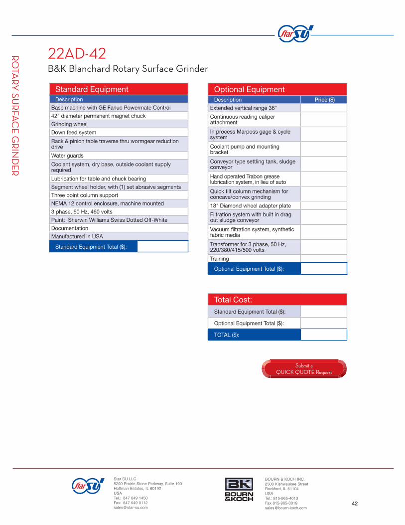
22AD-42B&K Blanchard Rotary Surface Grinder
STANDARD MACHINE SPECIFICATIONS
The Bourn & Koch Blanchard 22AD-42 Rotary Surface Grinder is a 48" swing diameter, vertical spindle, rotary surface grinder with a GE Fanuc Powermate control for the abrasive machining of parallelism, fl atness and surface fi nish to single or multiple piece production runs.
Technical Data - Capacities & LimitsGrinding wheel diameter 22"
Magnetic chuck diameter 42"
Swing diameter inside warterguards 48"
Vertical range 24"
Maximum load on chuck 3000 lbs
Grinding wheel horsepower (HP) 50
Type of feed system Servo
Down feed rates IPM .0001 - .100
Chuck rotation speeds RPM 6 to 24
Coolant capacity 250 gal
Height (Approximate) 109"
Length (Approximate) 140"
Width (Approximate) 69"
Weight (Approximate Net) 18300 lbs
Technical details subject to change without notice.
RO
TARY
SUR
FAC
E G
RIN
DE
R
Actual machine W-H-L and Weight depend on ordered confi guration. Technical data is subject to change without notice and may vary according to the workpiece geometry and options supplied. Workholding equipment supplied.
WHAT IS THE BLANCHARD LEGACY NUMBERING SYSTEM?
1. First digit(s) denotes the dia. of the grinding wheel in inches.2. Second set of digits denotes the dia. of the magnetic chuck in inches.3. “A” denotes all-electric confi guration (no mechanical feed box).
4. “C” denotes automatic cycle.
5. “D” denotes dry base construction. Outside coolant system required.
6. “E” denotes electronic “Auto-Zero II” automatic cycle.
7. “H” denotes high horsepower geared head design.
8. “K” denotes sludge conveyor option in wet base of machine.
9. No letter between numbers denotes standard wet base design.
41
Submit a QUICK QUOTE Request
Total Cost:Standard Equipment Total ($):
Optional Equipment Total ($):
TOTAL ($):
Standard EquipmentDescription
Base machine with GE Fanuc Powermate Control
42" diameter permanent magnet chuck
Grinding wheel
Down feed system
Rack & pinion table traverse thru wormgear reduction drive
Water guards
Coolant system, dry base, outside coolant supply required
Lubrication for table and chuck bearing
Segment wheel holder, with (1) set abrasive segments
Three point column support
NEMA 12 control enclosure, machine mounted
3 phase, 60 Hz, 460 volts
Paint: Sherwin Williams Swiss Dotted Off-White
Documentation
Manufactured in USA
Standard Equipment Total ($):
Optional EquipmentDescription Price ($)
Extended vertical range 36"
Continuous reading caliper attachment
In process Marposs gage & cycle system
Coolant pump and mounting bracket
Conveyor type settling tank, sludge conveyor
Hand operated Trabon grease lubrication system, in lieu of auto
Quick tilt column mechanism for concave/convex grinding
18" Diamond wheel adapter plate
Filtration system with built in drag out sludge conveyor
Vacuum fi ltration system, synthetic fabric media
Transformer for 3 phase, 50 Hz, 220/380/415/500 volts
Training
Optional Equipment Total ($):
RO
TARY
SUR
FAC
E G
RIN
DE
R
Star SU LLC5200 Prairie Stone Parkway, Suite 100Hoffman Estates, IL 60192USATel.: 847 649 1450Fax: 847 649 [email protected]
BOURN & KOCH INC.2500 Kishwaukee StreetRockford, IL 61104USATel.: 815-965-4013Fax [email protected]
22AD-42B&K Blanchard Rotary Surface Grinder
42

WWW.STAR-SU.COM
26HAD-48B&K Blanchard Rotary Surface Grinder
STANDARD MACHINE SPECIFICATIONS
The Bourn & Koch Blanchard 26HAD-48 Rotary Surface Grinder is a 56" swing diameter, vertical spindle, rotary surface grinder with a GE Fanuc Powermate control for the abrasive machining of parallelism, fl atness and surface fi nish to single or multiple piece production runs.
Technical Data - Capacities & LimitsGrinding wheel diameter 26"
Magnetic chuck diameter 48"
Swing diameter inside warterguards 56"
Vertical range 24"
Maximum load on chuck 3000 lbs
Grinding wheel horsepower (HP) 75
Type of feed system Servo
Down feed rates IPM .0001 - .100
Chuck rotation speeds RPM 6 to 24
Coolant capacity 500 gal
Height* (Approximate) 105"
Length (Approximate) 143"
Width (Approximate) 65"
Weight (Approximate Net) 18500 lbs
*Maximum height 115"Technical details subject to change without notice.
RO
TARY
SUR
FAC
E G
RIN
DE
R
Actual machine W-H-L and Weight depend on ordered confi guration. Technical data is subject to change without notice and may vary according to the workpiece geometry and options supplied. Workholding equipment supplied.
WHAT IS THE BLANCHARD LEGACY NUMBERING SYSTEM?
1. First digit(s) denotes the dia. of the grinding wheel in inches.2. Second set of digits denotes the dia. of the magnetic chuck in inches.3. “A” denotes all-electric confi guration (no mechanical feed box).
4. “C” denotes automatic cycle.
5. “D” denotes dry base construction. Outside coolant system required.
6. “E” denotes electronic “Auto-Zero II” automatic cycle.
7. “H” denotes high horsepower geared head design.
8. “K” denotes sludge conveyor option in wet base of machine.
9. No letter between numbers denotes standard wet base design.
43

RO
TARY
SUR
FAC
E G
RIN
DE
R
Star SU LLC5200 Prairie Stone Parkway, Suite 100Hoffman Estates, IL 60192USATel.: 847 649 1450Fax: 847 649 [email protected]
BOURN & KOCH INC.2500 Kishwaukee StreetRockford, IL 61104USATel.: 815-965-4013Fax [email protected]
26HAD-48B&K Blanchard Rotary Surface Grinder
Submit a QUICK QUOTE Request
Total Cost:Standard Equipment Total ($):
Optional Equipment Total ($):
TOTAL ($):
Standard EquipmentDescription
Base machine with GE Fanuc Powermate Control
48" diameter permanent magnet chuck
Grinding wheel
Down feed system
Rack & pinion table traverse thru wormgear reduction drive
Water guards
Coolant system, dry base, outside coolant supply required
Lubrication for table and chuck bearing
26" grinding wheel segment holder, one set of abrasive segments
Three point column support
NEMA 12 control enclosure, machine mounted
3 phase, 60 Hz, 460 volts
Paint: Sherwin Williams Swiss Dotted Off-White
Documentation
Manufactured in USA
Standard Equipment Total ($):
Optional EquipmentDescription Price ($)
Extended vertical range 36"
100 HP main spindle motor in place of 75 HP
In process Marposs gage & cycle system
Coolant pump and mounting bracket
Conveyor type settling tank, sludge conveyor
Hand operated Trabon grease lubrication system, in lieu of auto
Quick tilt column mechanism for concave/convex grinding
Filtration system with built in drag out sludge conveyor
Vacuum fi ltration system, synthetic fabric media
Variable frequency drive, for use only with CBN wheels
Transformer for 3 phase, 50 Hz, 220/380/415/500 volts
Training
Optional Equipment Total ($):
44

WWW.STAR-SU.COM
36HD-66B&K Blanchard Rotary Surface Grinder
STANDARD MACHINE SPECIFICATIONS
The Bourn & Koch Blanchard 36HD-66 Rotary Surface Grinder is an 84" swing diameter vertical spindle, rotary surface grinder with control for the abrasive machining of parallelism, fl atness and surface fi nish to single- or multiple-piece production runs.
Technical Data - Capacities & LimitsGrinding wheel diameter 36"
Magnetic chuck diameter 66"
Swing diameter inside warterguards 84"
Vertical range 24"
Maximum load on chuck 10000 lbs
Grinding wheel horsepower (HP) 150
Type of feed system pick-feed
Down feed rates IPM .004 - .080
Chuck rotation speeds RPM 5.6 - 20.1
Coolant capacity 1000 gal
Height* (Approximate) 81"
Length (Approximate) 91"
Width (Approximate) 55"
Weight (Approximate Net) 45000 lbs
*Maximum height 91"Technical details subject to change without notice.
RO
TARY
SUR
FAC
E G
RIN
DE
R
Actual machine W-H-L and Weight depend on ordered confi guration. Technical data is subject to change without notice and may vary according to the workpiece geometry and options supplied. Workholding equipment supplied.
WHAT IS THE BLANCHARD LEGACY NUMBERING SYSTEM?
1. First digit(s) denotes the dia. of the grinding wheel in inches.2. Second set of digits denotes the dia. of the magnetic chuck in inches.3. “A” denotes all-electric confi guration (no mechanical feed box).
4. “C” denotes automatic cycle.
5. “D” denotes dry base construction. Outside coolant system required.
6. “E” denotes electronic “Auto-Zero II” automatic cycle.
7. “H” denotes high horsepower geared head design.
8. “K” denotes sludge conveyor option in wet base of machine.
9. No letter between numbers denotes standard wet base design.
45

RO
TARY
SUR
FAC
E G
RIN
DE
R
Star SU LLC5200 Prairie Stone Parkway, Suite 100Hoffman Estates, IL 60192USATel.: 847 649 1450Fax: 847 649 [email protected]
BOURN & KOCH INC.2500 Kishwaukee StreetRockford, IL 61104USATel.: 815-965-4013Fax [email protected]
36HD-66B&K Blanchard Rotary Surface Grinder
Submit a QUICK QUOTE Request
Total Cost:Standard Equipment Total ($):
Optional Equipment Total ($):
TOTAL ($):
Standard EquipmentDescription
Base machine and controls
66" diameter permanent magnet chuck
Geared wheel head
Down feed system
Rack & pinion table traverse thru wormgear reduction drive
Water guards
Coolant system, dry base, ourside coolant supply required
Lubrication for table and chuck bearing
36" CDT segment wheel holder, with (1) set abrasive segments
Three point column support
NEMA 12 control enclosure, machine mounted
3 phase, 60 Hz, 460 volts
Paint: Sherwin Williams Swiss Dotted Off-White
Documentation
Manufactured in USA
Standard Equipment Total ($):
Optional EquipmentDescription Price ($)
CDTXL Segments - 12 sets, standard stock vitrifi ed bond specs
Extended vertical range 36"/40"
In process gage and cycle control system
200 HP Main spindle motor
Two coolant pumps with mounting brackets
Two solenoid controlled coolant valves
Self dumping swarf hopper
Pit-mounted conveyor drag-out setting tank
Training
Optional Equipment Total ($):
46

WWW.STAR-SU.COM
42HD-84B&K Blanchard Rotary Surface Grinder
STANDARD MACHINE SPECIFICATIONS
The Bourn & Koch Blanchard 42HD-84 Rotary Surface Grinder is an 84" swing diameter vertical spindle, rotary surface grinder with control for the abrasive machining of parallelism, fl atness and surface fi nish to single- or multiple- piece production runs.
Technical Data - Capacities & LimitsGrinding wheel diameter 42"
Magnetic chuck diameter 84"
Outside swing inside waterguards 96"
Swing diameter inside waterguards 85"
Verticle range 33"
Maximum load on chuck 22000 lbs
Grinding wheel horsepower (HP) 150
Type of feed system Servo
Down feed rates IPM .001 - .096
Chuck rotation speeds RPM 3.0 - 11.9
Coolant capacity 2000 gal
Height (Approximate) 168"
Length (Approximate) 249"
Width (Approximate) 113"
Weight (Approximate Net) 80500 lbs
Technical details subject to change without notice.
RO
TARY
SUR
FAC
E G
RIN
DE
R
Actual machine W-H-L and Weight depend on ordered confi guration. Technical data is subject to change without notice and may vary according to the workpiece geometry and options supplied. Workholding equipment supplied.
WHAT IS THE BLANCHARD LEGACY NUMBERING SYSTEM?
1. First digit(s) denotes the dia. of the grinding wheel in inches.2. Second set of digits denotes the dia. of the magnetic chuck in inches.3. “A” denotes all-electric confi guration (no mechanical feed box).
4. “C” denotes automatic cycle.
5. “D” denotes dry base construction. Outside coolant system required.
6. “E” denotes electronic “Auto-Zero II” automatic cycle.
7. “H” denotes high horsepower geared head design.
8. “K” denotes sludge conveyor option in wet base of machine.
9. No letter between numbers denotes standard wet base design.
47

RO
TARY
SUR
FAC
E G
RIN
DE
R
Star SU LLC5200 Prairie Stone Parkway, Suite 100Hoffman Estates, IL 60192USATel.: 847 649 1450Fax: 847 649 [email protected]
BOURN & KOCH INC.2500 Kishwaukee StreetRockford, IL 61104USATel.: 815-965-4013Fax [email protected]
42HD-84B&K Blanchard Rotary Surface Grinder
Submit a QUICK QUOTE Request
Total Cost:Standard Equipment Total ($):
Optional Equipment Total ($):
TOTAL ($):
Standard EquipmentDescription
Extra heavy, double wall close grain casting with integral sloping shelf
84" diameter magnet chuck
Traverse rack mounted on the table
Wheel head made of heavily ribbed casting
Three point column support
Vertical power down feed system
Steel sheet water guards
Drive motor with absolute position encoder feedback system
External coolant storage
Oil pump circulates in impulse feed box
Paint: Swiss White, Steel Blue, Machine Tool Gray or Vista Green
1 operator's handbook and necessary adjusting wrenches
Manufactured in USA
Standard Equipment Total ($):
Optional EquipmentDescription Price ($)
12 sets CDTXL segments
Extended vertical range 45"/60"
200 HP main spindle motor
250 HP main spindle motor
300 HP main spindle motor
2 coolant pumps
2 solenoid controlled coolant valves
Pit-mounted conveyor drag-out settling tank
Self-dumping swarf hopper
50-cycle electrical supply
Condensed training (no charge)
Operator/setup course (24 hours)
Mechanical, lubrication, mainte-nance, troubleshooting course
Electrical, electronic maintenance, troubleshooting course
Operator training, machine setup assistance, in-plant training
Optional Equipment Total ($):
48

WWW.STAR-SU.COM
72HD-120-144B&K Blanchard Rotary Surface Grinder
STANDARD MACHINE SPECIFICATIONS
The Bourn & Koch Blanchard 72HD-120-144 Rotary Surface Grinder is an 84" swing diameter vertical spindle, rotary surface grinder with control for the abrasive machining of parallelism, fl atness and surface fi nish to single- or multiple-piece production runs.
Technical Data - Capacities & LimitsGrinding wheel diameter 72"
Magnetic chuck diameter 120"
Swing diameter inside warterguards 144"
Vertical range 33"
Maximum load on chuck 30000 lbs
Grinding wheel horsepower (HP) 200
Type of feed system Servo
Down feed rates IPM .001 - .096
Chuck rotation speeds RPM 2.6 - 10.2
Coolant capacity 3000 gal
Height (Approximate) 220"
Length (Approximate) 299"
Width (Approximate) 150"
Weight (Approximate Net) 103000 lbs
RO
TARY
SUR
FAC
E G
RIN
DE
R
Actual machine W-H-L and Weight depend on ordered confi guration. Technical data is subject to change without notice and may vary according to the workpiece geometry and options supplied. Workholding equipment supplied.
WHAT IS THE BLANCHARD LEGACY NUMBERING SYSTEM?
1. First digit(s) denotes the dia. of the grinding wheel in inches.2. Second set of digits denotes the dia. of the magnetic chuck in inches.3. “A” denotes all-electric confi guration (no mechanical feed box).
4. “C” denotes automatic cycle.
5. “D” denotes dry base construction. Outside coolant system required.
6. “E” denotes electronic “Auto-Zero II” automatic cycle.
7. “H” denotes high horsepower geared head design.
8. “K” denotes sludge conveyor option in wet base of machine.
9. No letter between numbers denotes standard wet base design.
Technical details subject to change without notice.
49

RO
TARY
SUR
FAC
E G
RIN
DE
R
Star SU LLC5200 Prairie Stone Parkway, Suite 100Hoffman Estates, IL 60192USATel.: 847 649 1450Fax: 847 649 [email protected]
BOURN & KOCH INC.2500 Kishwaukee StreetRockford, IL 61104USATel.: 815-965-4013Fax [email protected]
72HD-120-144B&K Blanchard Rotary Surface Grinder
Submit a QUICK QUOTE Request
Total Cost:Standard Equipment Total ($):
Optional Equipment Total ($):
TOTAL ($):
Standard EquipmentDescription
Base machine extra heavy, double wall close grain casting
120" diameter magnet chuck
Traverse rack mounted on the table
Wheel head made of heavily ribbed casting
Three point column support
Geared wheel head
Blanchard CDT segment wheel holder, one set of abrasive segments
Vertical power down feed system
Steel sheet water guards
Drive motor with absolute position encoder feedback system
External coolant storage, dry base design
Oil pump circulates in impulse feed box
Floor mounted NEMA 12 electrical enclosure
Paint: Swiss White, Steel Blue, Machine Tool Gray or Vista Green
1 operator's handbook and necessary adjusting wrenches
Manufactured in USA
Standard Equipment Total ($):
Optional EquipmentDescription Price ($)
Extended vertical range to 45"
Extended vertical range to 60"
250 HP main spindle motor
300 HP main spindle motor
Power factor capacitors for 15 HP chuck rotation motor
Power factor capacitors for 200 HP chuck rotation motor
Power factor capacitors for 250 HP chuck rotation motor
Power factor capacitors for 300 HP chuck rotation motor
2 coolant pumps
2 solenoid controlled coolant valves
Coolant fi ltration system
Condensed training (no charge)
Operator/setup course (24 hours)
Mechanical, lubrication, mainte-nance, troubleshooting course
Electrical, electronic maintenance, troubleshooting course
Operator training, machine setup assistance, in-plant training
Optional Equipment Total ($):
50

WWW.STAR-SU.COM
76HD-120-164B&K Blanchard Rotary Surface Grinder
STANDARD MACHINE SPECIFICATIONS
The Bourn & Koch Blanchard 76HD-120-164 Rotary Surface Grinder is an 84" swing diameter vertical spindle, rotary surface grinder with control for the abrasive machining of parallelism, fl atness and surface fi nish to single- or multiple- piece production runs.
Technical Data - Capacities & LimitsGrinding wheel diameter 76"
Magnetic chuck diameter 120"
Swing diameter inside warterguards 164"
Vertical range 33"/60"
Maximum load on chuck 30000 lbs
Grinding wheel horsepower (HP) *200/*300
Type of feed system Servo
Down feed rates IPM .001 - .1000
Chuck rotation speeds RPM 3, 4.8, 7.8, 11.9
Coolant capacity 2000 gal
Height (Approximate) 220"
Length (Approximate) 299"
Width (Approximate) 170"
Weight (Approximate Net) 103000 lbs
RO
TARY
SUR
FAC
E G
RIN
DE
R
Actual machine W-H-L and Weight depend on ordered confi guration. Technical data is subject to change without notice and may vary according to the workpiece geometry and options supplied. Workholding equipment supplied.
WHAT IS THE BLANCHARD LEGACY NUMBERING SYSTEM?
1. First digit(s) denotes the dia. of the grinding wheel in inches.2. Second set of digits denotes the dia. of the magnetic chuck in inches.3. “A” denotes all-electric confi guration (no mechanical feed box).
4. “C” denotes automatic cycle.
5. “D” denotes dry base construction. Outside coolant system required.
6. “E” denotes electronic “Auto-Zero II” automatic cycle.
7. “H” denotes high horsepower geared head design.
8. “K” denotes sludge conveyor option in wet base of machine.
9. No letter between numbers denotes standard wet base design.
Technical details subject to change without notice.
51

RO
TARY
SUR
FAC
E G
RIN
DE
R
Star SU LLC5200 Prairie Stone Parkway, Suite 100Hoffman Estates, IL 60192USATel.: 847 649 1450Fax: 847 649 [email protected]
BOURN & KOCH INC.2500 Kishwaukee StreetRockford, IL 61104USATel.: 815-965-4013Fax [email protected]
76HD-120-164B&K Blanchard Rotary Surface Grinder
Submit a QUICK QUOTE Request
Total Cost:Standard Equipment Total ($):
Optional Equipment Total ($):
TOTAL ($):
Standard EquipmentDescription
Base machine extra heavy, double wall close grain casting
120" diameter magnet chuck
Hydraulic table traverse
Wheel head made of heavily ribbed casting
Three point column support
Geared wheel head
Blanchard CDT segment wheel holder, one set of abrasive segments
Vertical power down feed system
Steel sheet water guards
Drive motor with absolute position encoder feedback system
External coolant storage, dry base design
Oil pump circulates in impulse feed box
Floor mounted NEMA 12 electrical enclosure
Paint: Swiss White, Steel Blue, Machine Tool Gray or Vista Green
1 operator's handbook and necessary adjusting wrenches
Manufactured in USA
Standard Equipment Total ($):
Optional EquipmentDescription Price ($)
250 HP main spindle motor
300 HP main spindle motor
Power factor capacitors for 15 HP chuck rotation motor
Power factor capacitors for 200 HP chuck rotation motor
Power factor capacitors for 250 HP chuck rotation motor
2 coolant pumps
2 solenoid controlled coolant valves
Coolant fi ltration system
Condensed training (no charge)
Operator/setup course (24 hours)
Mechanical, lubrication, mainte-nance, troubleshooting course
Electrical, electronic maintenance, troubleshooting course
Operator training, machine setup assistance, in-plant training
Optional Equipment Total ($):
52

WWW.STAR-SU.COM
119 VNCB&K Motch Single Spindle Vertical Chucker
STANDARD MACHINE SPECIFICATIONS
The Bourn & Koch Motch 119VNC is a 25" swing diameter vertical chucker, with a GE Fanuc 21iT CNC control for the chucking and vertical machining of a wide range of cylindrical components in single or multiple piece production runs.
Technical Data - Capacities & LimitsSwing diameter 25"
Spindle Nose A2-11
Spindle Speed Range (RPM) 280-2800
X axis slide travel (work area) 12.5"
Y axis slide travel (load area)
Z axis slide travel 17"
Feed rate X & Z (ipm) 0-125"
No. of turret stations 6
HP 50
Height (Approximate)
Length (Approximate)
Width (Approximate)
Weight (Approximate Net) 12100 lbs
Technical details subject to change without notice.
SING
LE SP
IND
LE V
ERTIC
AL C
HU
CK
ER
Actual machine W-H-L and Weight depend on ordered confi guration. Technical data is subject to change without notice and may vary according to the workpiece geometry and options supplied. Workholding equipment supplied.
53

SING
LE SP
IND
LE V
ERTIC
AL C
HU
CK
ER
Star SU LLC5200 Prairie Stone Parkway, Suite 100Hoffman Estates, IL 60192USATel.: 847 649 1450Fax: 847 649 [email protected]
BOURN & KOCH INC.2500 Kishwaukee StreetRockford, IL 61104USATel.: 815-965-4013Fax [email protected]
119 VNCB&K Motch Single Spindle Vertical Chucker
Submit a QUICK QUOTE Request
Total Cost:Standard Equipment Total ($):
Optional Equipment Total ($):
TOTAL ($):
Standard EquipmentDescription
Base machine with GE 21iT CNC Control, swiveling pendant
6 station hex turret for up to 12 tools
Precision spindle, American Std fl ange nose
Coolant distribution for turret and chip fl ush
Spindle load meter
6" hydraulic chuck actuator with drawbar
ID/OD chuck clamping, presettable pressure
Automatic powered door, dual push button control
Totally enclosed chip and splash guards
Work light
Sealed electric cabinet with safety interlock and fans
3 phase, 60 Hz, 460 volts
Willy Vogel centralized lube system with safety interlocks
Absolute encodes to retain position during power failure
Leveling screws
Paint: Sherwin Williams Swiss Dotted Off-White
Documentation
Manufactured in USA
Standard Equipment Total ($):
Optional EquipmentDescription Price ($)
Power operated elevating chip conveyor, rear 42" discharge
Magnetic chip conveyor
Rosedale bag for fi ne fi ltration
Low level coolant switch
Oil skimmer
“X” axis linear scale in lieu of encoder
Foot pedal for chuck open/close
75 HP AC spindle motor (900 rpm)
Spindle orient package
150 - 1500 RPM Main Spindle Speed Range
300 - 3000 RPM Main Spindle Speed Range
30 HP High Torque spindle drive motor
Air Conditioner for Electrical Enclosure in lieu of standard Fan
Contact Making Spindle Load Meter, pre-settable via “M” Code
Spiral Bevel Gear Spindle Drive
Special Guard for Robotic Load, including robotic interface
Stack light
6" diameter manifold for customer supplied mist collector
Tool probe, column mounted
Turret mounted part probe
Set of leveling plates and anchor bolts
Warranty extension to second year
Workholding options
GE Fanuc 21iT CNC control options
Turret tooling
Transformer for 3 phase, 50 Hz, 220/380/415/500 volts
Training
Optional Equipment Total ($):
54

WWW.STAR-SU.COM
125 VNCB&K Motch Single Spindle Vertical Chucker
STANDARD MACHINE SPECIFICATIONS
The Bourn & Koch Motch 125VNC is a 25" swing diameter vertical chucker, with a GE Fanuc 16i control for the chucking and vertical machining of a wide range of cylindrical components in single or multiple piece production runs.
Technical Data - Capacities & LimitsSwing diameter 25"
Spindle Nose A2-11
Spindle Speed Range (RPM) 240-2410
Maximum number of tools 12
X axis slide travel (work area) 20"
Y axis slide travel (load area)
Z axis slide travel 18"
Feed rate X & Z (ipm) 0-125"
No. of turret stations 6/8
HP 75
Height* (Approximate)
Length (Approximate)
Width (Approximate)
Weight (Approximate Net) 18600 lbs
*Maximum height 91"Technical details subject to change without notice.
SING
LE SP
IND
LE V
ERTIC
AL C
HU
CK
ER
Actual machine W-H-L and Weight depend on ordered confi guration. Technical data is subject to change without notice and may vary according to the workpiece geometry and options supplied. Workholding equipment supplied.
55

SING
LE SP
IND
LE V
ERTIC
AL C
HU
CK
ER
Star SU LLC5200 Prairie Stone Parkway, Suite 100Hoffman Estates, IL 60192USATel.: 847 649 1450Fax: 847 649 [email protected]
BOURN & KOCH INC.2500 Kishwaukee StreetRockford, IL 61104USATel.: 815-965-4013Fax [email protected]
125 VNCB&K Motch Single Spindle Vertical Chucker
Submit a QUICK QUOTE Request
Total Cost:Standard Equipment Total ($):
Optional Equipment Total ($):
TOTAL ($):
Standard EquipmentDescription
Base machine with GE 21iT CNC Control, swiveling pendant
4 or 6 station hex turret
Precision spindle, American Std fl ange nose
Coolant distribution for turret and chip fl ush
Spindle load meter
6" hydraulic chuck actuator with drawbar
ID/OD chuck clamping, presettable pressure
Automatic powered door, dual push button control
Totally enclosed chip and splash guards
Work light
Sealed electric cabinet with safety interlock and fans
3 phase, 60 Hz, 460 volts
Willy Vogel centralized lube system with safety interlocks
Absolute encodes to retain position during power failure
Leveling screws
Paint: Sherwin Williams Swiss Dotted Off-White
Documentation
Manufactured in USA
Standard Equipment Total ($):
Optional EquipmentDescription Price ($)
Power operated elevating chip conveyor, rear 42" discharge
Magnetic chip conveyor
Rosedale bag for fi ne fi ltration
Low level coolant switch
Oil skimmer
“X” axis linear scale in lieu of encoder
“Z” axis linear scale in lieu of encoder
Foot pedal for chuck open/close
Spindle orient package
150 - 1500 RPM Main Spindle Speed Range
AC for Electrical Enclosure in lieu of standard heat exchanger
Contact Making Spindle Load Meter, pre-settable via “M” Code
Stack light
Mist/Dust Collector, stand-alone
6" diameter manifold for customer supplied mist collector
Spiral Bevel Gear Spindle Drive
Two speed gear box for bevel spindle drive
Special Guard for Robotic Load, including robotic interface
Tool probe, column mounted
Turret mounted part probe
7" additional “Z” axis stroke extension
5-7" column riser to increase vertical clearance
Steel telescopic way guards for “X” Axis
Set of leveling plates and anchor bolts
Warranty extension to second year
Workholding options
GE Fanuc 21iT CNC control options
Turret tooling options
Quick change tooling options
Transformer for 3 phase, 50 Hz, 220/380/415/500 volts
Training
Optional Equipment Total ($):
56

WWW.STAR-SU.COM
135 VNCB&K Motch Single Spindle Vertical Chucker
STANDARD MACHINE SPECIFICATIONS
The Bourn & Koch Motch 135 VNC is a 35" swing diameter vertical chucker, with a GE Fanuc 16i control for the chucking and vertical machining of a wide range of cylindrical components in single or multiple piece production runs.
Technical Data - Capacities & LimitsSwing diameter 35"
Spindle Nose A2-15
Spindle Speed Range (RPM) 100-1000
Maximum number of tools 12
X axis slide travel (work area) 28"
Y axis slide travel (load area)
Z axis slide travel 24"
Feed rate X & Z (ipm) 0-125"
No. of turret stations 6
HP 75
Height* (Approximate)
Length (Approximate)
Width (Approximate)
Weight (Approximate Net) 28500 lbs
*Maximum height 91"Technical details subject to change without notice.
SING
LE SP
IND
LE V
ERTIC
AL C
HU
CK
ER
Actual machine W-H-L and Weight depend on ordered confi guration. Technical data is subject to change without notice and may vary according to the workpiece geometry and options supplied. Workholding equipment supplied.
57

SING
LE SP
IND
LE V
ERTIC
AL C
HU
CK
ER
Star SU LLC5200 Prairie Stone Parkway, Suite 100Hoffman Estates, IL 60192USATel.: 847 649 1450Fax: 847 649 [email protected]
BOURN & KOCH INC.2500 Kishwaukee StreetRockford, IL 61104USATel.: 815-965-4013Fax [email protected]
135 VNCB&K Motch Single Spindle Vertical Chucker
Submit a QUICK QUOTE Request
Total Cost:Standard Equipment Total ($):
Optional Equipment Total ($):
TOTAL ($):
Standard EquipmentDescription
Base machine with GE 21iT CNC Control, swiveling pendant
4 or 6 station hex turret
Precision spindle, American Std fl ange nose
Coolant distribution for turret and chip fl ush
Spindle load meter
6" hydraulic chuck actuator with drawbar
ID/OD chuck clamping, presettable pressure
Automatic powered door, dual push button control
Totally enclosed chip and splash guards
Work light
Sealed electric cabinet with safety interlock and fans
3 phase, 60 Hz, 460 volts
Willy Vogel centralized lube system with safety interlocks
Absolute encodes to retain position during power failure
Leveling screws
Paint: Sherwin Williams Swiss Dotted Off-White
Documentation
Manufactured in USA
Standard Equipment Total ($):
Optional EquipmentDescription Price ($)
Power operated elevating chip conveyor, rear 42" discharge
Magnetic chip conveyor
Rosedale bag for fi ne fi ltration
Low level coolant switch
Oil skimmer
“X” axis linear scale in lieu of encoder
“Z” axis linear scale in lieu of encoder
Foot pedal for chuck open/close
Spindle orient package
150 - 1500 RPM Main Spindle Speed Range
AC for Electrical Enclosure in lieu of standard heat exchanger
Contact Making Spindle Load Meter, pre-settable via “M” Code
Stack light
Mist/Dust Collector, stand-alone
6" diameter manifold for customer supplied mist collector
Two speed gear box for bevel spindle drive
Spiral Bevel Gear Spindle Drive
Tool probe, column mounted
Turret mounted part probe
6" additional “Z” axis stroke extension
12" additional “Z” axis stroke extension
6" column riser to increase vertical clearance
12" column riser to increase vertical clearance
Steel telescopic way guards for “X” axis
Set of leveling plates and anchor bolts
Warranty extension to second year
Working options
GE Fanuc 21iT CNC control options
Turret tooling options
Quick change tooling options
Transformer for 3 phase, 50 Hz, 220/380/415/500 volts
Training
Optional Equipment Total ($):
58

WWW.STAR-SU.COM
1000VBGVertical Grinding Machine
STANDARD MACHINE SPECIFICATIONS
CNC Vertical Grinder, with cross slide for internal/external grinding of cylindrical workpieces, using a Siemens 840D CNC control with linear and circular interpolation, via B&K HMI graphic supported menu style data input with simple selection of:
- grinding process
- tool management
- part recall and process data
- inch-metric programmable, absolute and incremental
- Windows XP environment
- No CNC programming knowledge required
- HMI calculates cycle time
VE
RTICA
L GR
IND
ING
Actual machine W-H-L and Weight depend on ordered confi guration. Technical data is subject to change without notice and may vary according to the workpiece geometry, the loading system and the workholding equipment supplied.
Technical Data - Capacities & LimitsWork spindle maximum swing 1100 mm
Swing 430 mm above worktable 850 mm
Worktable diameter 1000 mm
A2 spindle nose - ASA standard 203.2 mm
Accuracy, run-out, caming 0.0025 mm
Grinding head nominal hole depth 450 mm
Slide travel - vertical “Z” axis 700 mm
Slide travel - horizontal “X” axis 825 mm
Right of center 800 mm
Maximum table weight for worktable 2000 kg
Slide traverse rates for X and Z axis 7500 mm/min
Slide feed rates for X and Z axis 1250 mm/min
Motor, grinding wheel spindle 7.5 KW
Weight (approximate net) 16,364 kg
59

VE
RTICA
L GR
IND
ING
1000VBGCNC Vertical Grinder
Submit a QUICK QUOTE Request
Total Cost:Standard Equipment Total ($):
Optional Equipment Total ($):
TOTAL ($):
Standard EquipmentDescription
Heavy stress relieved steel weldment base, polymer composite fi lled
Heavy stress relieved steel weldment column, polymer composite fi lled
Cross slide and self contained grinding head
Vertical columns are heavy, one-piece weldment of high grade
Precision linear roller guide ways and ball screws
Self contained workspindle
Automatic CNC controlled guide way and ball screw lubrication
Coolant system, including pump, motor, piping, valves, settling tank
Single point diamond dresser
+/-45° Vertical Slide Swivel
Linear scale feed on both axes
Siemens 840D CNC Control
HMI for standard grinding cycles
Infi nitely controlled spindle speeds via CNC
Dry fl oor machine enclosure with sliding doors
Leveling screws
Machine enclosure light
Paint: One standard Polane color
Documentation
CE compliant
ANSI and NFPA compliant
Manufactured in USA
Standard Equipment Total ($):
Optional EquipmentDescription Price ($)
1000 mm Diameter work table
CNC contouring rotary table “C” axis
CNC rotary swivel “B” axis
SETCO grinding spindle, motorized
Remote pulse generator
Chuck actuating equipment
Barnes fi ltration coolant system
Integrated RC inspection system
Circular geometry software
Optional roll dresser with software
Special cam grinding software
Contact probing of the part
Hard turning process
Acoustic emission sensing adaptive control
Gap elimination
Multiple grinding spindles, probing, hard turning HMI support
Automatic tool changer
Live milling/drilling tool attachments
Optional Equipment Total ($):
Star SU LLC5200 Prairie Stone Parkway, Suite 100Hoffman Estates, IL 60192USATel.: 847 649 1450Fax: 847 649 [email protected]
60

WWW.STAR-SU.COM
18CNCB&K Springfi eld CNC Vertical Grinder Crown Type
STANDARD MACHINE SPECIFICATIONS
CNC Vertical Grinder, Crown Type for internal/external grinding of cylindrical workpieces, using a GE Fanuc 21iT CNC control with linear and circular interpolation, inch-metric programmable, absolute and incremental programming providing:
Rapid traverse on both vertical and horizontal axes
Vector Grind interpolation of x and z axles for taper grinding
Vertical Oscillation with horizontal feed and tarry and dwell
Continuous feed in both horizontal and vertical directions
Gap Elimination
Standard Cycles
Technical Data - Capacities & LimitsWork spindle maximum swing 23 in
Work spindle speed 6-120 rpm
A2 spindle nose - ASA standard 8 in
Accuracy, run-out and camming at spindle nose 0.0001 in
Grinding head nominal hole depth 8 in
Grinding head stroke 14 in
Slide traverse rates for X and Z axis 300 ipm
Slide feed rates for X and Z axis 200 ipm
Weight (Approximate Net) 9500 lbs
Technical data is subject to change without notice.
VE
RTICA
L GR
IND
ER
Actual machine W-H-L and Weight depend on ordered confi guration. Technical data is subject to change without notice and may vary according to the workpiece geometry and options supplied. Workholding equipment supplied.
Machine with Full Enclosure
Machine with Standard Guarding
61

VE
RTICA
L GR
IND
ER
Star SU LLC5200 Prairie Stone Parkway, Suite 100Hoffman Estates, IL 60192USATel.: 847 649 1450Fax: 847 649 [email protected]
BOURN & KOCH INC.2500 Kishwaukee StreetRockford, IL 61104USATel.: 815-965-4013Fax [email protected]
18CNCB&K Springfi eld CNC Vertical Grinder Crown Type
Submit a QUICK QUOTE Request
Total Cost:Standard Equipment Total ($):
Optional Equipment Total ($):
TOTAL ($):
Standard EquipmentDescription
Heavy stress-relieved steel weldment base
Heavy stress-relieved steel weldment crown
Self-contained work spindle
Cross slide and grinding head
Automatic CNC controlled lubrication
Coolant system, including pump, motor, piping, valves, settling tank
Single point dresser
Heidenhain linear scale feed on both axes
GE Fanuc 21iT CNC
Gap eliminator
Standard grinding cycles
Frequency variator of table and spindle variable speeds
Splash guard with manual doors and safety interlocks
Leveling screws
Centralized lubrication system
Paint: One standard Polane color
Documentation
Manufactured in USA
Standard Equipment Total ($):
Optional EquipmentDescription Price ($)
18" diameter work table
4" face plate jaws
Dial indicator angle setting attachment
Rotary diamond roll dresser
Disposable media type fi ltration system
Hydraulic acutating equipment
4" riser under crown
18" swing water guards and sliding water guard door
6" riser under crown
10" riser under crown
Heavy-duty cartridge type grinding spindle (7700 RPM)
Extra grinding spindle pulleys
Extra grinding spindle belts
Wheel guards for O.D. grinding
Full machine enclosure
Additional machine manuals
Condensed training (no charge)
Operator/setup course (24 hours)
Mechanical, lubrication, maintenance, troubleshooting course
Electrical, electronic maintenance, troubleshooting course
Operator training, machine setup assistance, in-plant training
Optional Equipment Total ($):
62

WWW.STAR-SU.COM
36CNCB&K Springfi eld Vertical Grinder Crown Type
STANDARD MACHINE SPECIFICATIONS
CNC Vertical Grinder, Crown Type for internal/external grinding of cylindrical workpieces, using a GE Fanuc 21iT CNC control with linear and circular interpolation, inch-metric programmable, absolute and incremental programming providing:
Rapid traverse on both vertical and horizontal axes
Vector Grind interpolation of x and z axles for taper grinding
Vertical Oscillation with horizontal feed and tarry and dwell
Continuous feed in both horizontal and vertical directions
Gap Elimination
Standard Cycles
Technical Data - Capacities & LimitsWork spindle maximum swing 44 in
Work spindle speed 6-120 rpm
A2 spindle nose - ASA standard 8 in
Accuracy, run-out and camming at spindle nose 0.0001 in
Grinding head nominal hole depth 18 in
Grinding head stroke 28 in
Clearance over work table 20 in
Slide traverse rates for X and Z axis 300 ipm
Slide feed rates for X and Z axis .0001 in - 50 in
Coolant capacity 50 gal
Weight (Approximate Net) 17500 lbs
Technical data is subject to change without notice.
VE
RTICA
L GR
IND
ER
Actual machine W-H-L and Weight depend on ordered confi guration. Technical data is subject to change without notice and may vary according to the workpiece geometry and options supplied. Workholding equipment supplied.
Machine with Full Enclosure
Machine with Standard Guarding
63

VE
RTICA
L GR
IND
ER
Star SU LLC5200 Prairie Stone Parkway, Suite 100Hoffman Estates, IL 60192USATel.: 847 649 1450Fax: 847 649 [email protected]
BOURN & KOCH INC.2500 Kishwaukee StreetRockford, IL 61104USATel.: 815-965-4013Fax [email protected]
36CNCB&K Springfi eld Vertical Grinder Crown Type
Submit a QUICK QUOTE Request
Total Cost:Standard Equipment Total ($):
Optional Equipment Total ($):
TOTAL ($):
Standard EquipmentDescription
Heavy stress-relieved steel weldment base
Heavy stress-relieved steel weldment crown
Self-contained work spindle
Cross slide and grinding head
Automatic CNC controlled lubrication
Coolant system, including pump, motor, piping, valves, settling tank
Single point dresser
Heidenhain linear scale feed on both axes
GE Fanuc 21iT CNC
Gap eliminator
Standard grinding cycles
Frequency variator of table and spindle variable speeds
Splash guard with manual doors and safety interlocks
Leveling screws
Centralized lubrication system
Paint: One standard Polane color
Documentation
Manufactured in USA
Standard Equipment Total ($):
Optional EquipmentDescription Price ($)
36" diameter work table
42" diameter work table
4" face plate jaws
Dial indicator angle setting attachment
Rotary diamond roll dresser
Disposable media type fi ltration system
Hydraulic acutating equipment
4" riser under crown
18" swing water guards and sliding water guard door
6" riser under crown
10" riser under crown
Heavy-duty cartridge type grinding spindle (7700 RPM, Model 3502)
Heavy-duty cartridge type grinding spindle (4300 RPM, Model 3513)
Extra grinding spindle pulleys
Extra grinding spindle belts
Wheel guards for O.D. grinding
Full machine enclosure
Additional machine manuals
Setco quill type spindle 3102A
Setco quill model 1222 or 1227
Add second grinding slide
Condensed training (no charge)
Operator/setup course (24 hours)
Mechanical, lubrication, maintenance, troubleshooting course
Electrical, electronic maintenance, troubleshooting course
Operator training, machine setup assistance, in-plant training
Optional Equipment Total ($):
64

WWW.STAR-SU.COM
42CNCB&K Springfi eld Vertical Grinder Rail Type
STANDARD MACHINE SPECIFICATIONS
CNC Vertical Grinder, Rail Type for internal/external grinding of cylindrical workpieces, using a GE Fanuc 21iT CNC control with linear and circular interpolation, inch-metric programmable, absolute and incremental programming providing:
Rapid traverse on both vertical and horizontal axes
Vector Grind interpolation of x and z axles for taper grinding
Vertical Oscillation with horizontal feed and tarry and dwell
Continuous feed in both horizontal and vertical directions
Gap Elimination
Standard Cycles
Technical Data - Capacities & LimitsWork spindle maximum swing 50 in
Work spindle speed 6-120 rpm
A2 spindle nose - ASA standard 8 in
Accuracy, run-out and camming at spindle nose 0.0001 in
Grinding head nominal hole depth 18 in
Grinding head stroke 28 in
Clearance over work table 12 - 36 in
Slide traverse rates for X and Z axis 300 ipm
Slide feed rates for X and Z axis .0001 in - 50 in
Coolant capacity 50 gal
Weight (Approximate Net) 34000 lbs
Technical data is subject to change without notice.
VE
RTICA
L GR
IND
ER
Actual machine W-H-L and Weight depend on ordered confi guration. Technical data is subject to change without notice and may vary according to the workpiece geometry and options supplied. Workholding equipment supplied.
Machine with Full Enclosure
Machine with Standard Guarding
65

VE
RTICA
L GR
IND
ER
Star SU LLC5200 Prairie Stone Parkway, Suite 100Hoffman Estates, IL 60192USATel.: 847 649 1450Fax: 847 649 [email protected]
BOURN & KOCH INC.2500 Kishwaukee StreetRockford, IL 61104USATel.: 815-965-4013Fax [email protected]
42CNCB&K Springfi eld Vertical Grinder Rail Type
Submit a QUICK QUOTE Request
Total Cost:Standard Equipment Total ($):
Optional Equipment Total ($):
TOTAL ($):
Standard EquipmentDescription
Heavy stress-relieved steel weldment base
Self-contained work spindle
Cross slide and grinding head
Vertical columns are heavy, one-piece castings of high grade
Cross-rail elevating mechanism
Automatic CNC controlled lubrication
Coolant system, including pump, motor, piping, valves, settling tank
Single point dresser
+/-45° vertical slide swivel
Heidenhain linear scale feed on both axes
GE Fanuc 21iT CNC
Gap eliminator
Standard grinding cycles
Frequency variator of table and spindle variable speeds
Splash guard with manual doors and safety interlocks
Leveling screws
Centralized lubrication system
Paint: One standard Polane color
Documentation
Manufactured in USA
Standard Equipment Total ($):
Optional EquipmentDescription Price ($)
42" diameter work table
4" face plate jaws
Dial indicator angle setting attachment
Rotary diamond roll dresser
Disposable media type fi ltration system
Hydraulic acutating equipment
4" riser under crown
Heavy-duty cartridge type grinding spindle (7700 RPM, Model 3502)
Heavy-duty cartridge type grinding spindle (4300 RPM, Model 3513)
Extra grinding spindle pulleys
Extra grinding spindle belts
Wheel guards for O.D. grinding
Full machine enclosure
Additional machine manuals
Manual or electro magnetic chuck
Condensed training (no charge)
Operator/setup course (24 hours)
Mechanical, lubrication, maintenance, troubleshooting course
Electrical, electronic maintenance, troubleshooting course
Operator training, machine setup assistance, in-plant training
Optional Equipment Total ($):
66

WWW.STAR-SU.COM
48CNCB&K Springfi eld Vertical Grinder Rail Type
STANDARD MACHINE SPECIFICATIONS
CNC Vertical Grinder, Rail Type for internal/external grinding of cylindrical workpieces, using a GE Fanuc 21iT CNC control with linear and circular interpolation, inch-metric programmable, absolute and incremental programming providing:
Rapid traverse on both vertical and horizontal axes
Vector Grind interpolation of x and z axles for taper grinding
Vertical Oscillation with horizontal feed and tarry and dwell
Continuous feed in both horizontal and vertical directions
Gap Elimination
Standard Cycles
Technical Data - Capacities & LimitsWork spindle maximum swing 60 in
Work spindle speed 5-100 rpm
A2 spindle nose - ASA standard 15 in
Accuracy, run-out and camming at spindle nose 0.0003 in
Grinding head nominal hole depth 24.5 in
Grinding head stroke 36 in
Clearance over work table 12-60 in
Slide traverse rates for X and Z axis 300 ipm
Slide feed rates for X and Z axis .0001 in - 50 in
Coolant capacity 50 gal
Weight (Approximate Net) 44200 lbs
Technical data is subject to change without notice.
VE
RTICA
L GR
IND
ER
Actual machine W-H-L and Weight depend on ordered confi guration. Technical data is subject to change without notice and may vary according to the workpiece geometry and options supplied.Workholding equipment supplied.
Machine with Full Enclosure
Machine with Standard Guarding
67

VE
RTICA
L GR
IND
ER
Star SU LLC5200 Prairie Stone Parkway, Suite 100Hoffman Estates, IL 60192USATel.: 847 649 1450Fax: 847 649 [email protected]
BOURN & KOCH INC.2500 Kishwaukee StreetRockford, IL 61104USATel.: 815-965-4013Fax [email protected]
48CNCB&K Springfi eld Vertical Grinder Rail Type
Submit a QUICK QUOTE Request
Total Cost:Standard Equipment Total ($):
Optional Equipment Total ($):
TOTAL ($):
Standard EquipmentDescription
Heavy stress-relieved steel weldment base
Self-contained work spindle
Cross slide and grinding head
Vertical columns are heavy, one-piece castings of high grade
Cross-rail elevating mechanism
Automatic CNC controlled lubrication
Coolant system, including pump, motor, piping, valves, settling tank
Single point dresser
+/-45° vertical slide swivel
Heidenhain linear scale feed on both axes
GE Fanuc 21iT CNC
Gap eliminator
Standard grinding cycles
Frequency variator of table and spindle variable speeds
Splash guard with manual doors and safety interlocks
Leveling screws
Centralized lubrication system
Paint: One standard Polane color
Documentation
Manufactured in USA
Standard Equipment Total ($):
Optional EquipmentDescription Price ($)
48" diameter work table
4" face plate jaws
Dial indicator angle setting attachment
Rotary diamond roll dresser
Disposable media type fi ltration system
Hydraulic acutating equipmentHeavy-duty cartridge type grinding spindle (7700 RPM, Model 3602)Heavy-duty cartridge type grinding spindle (4300 RPM, Model 3613)Extra grinding spindle pulleys
Extra grinding spindle belts
Wheel guards for O.D. grinding
Full machine enclosure
Additional machine manuals
Manual or electro magnetic chuck
Condensed training (no charge)
Operator/setup course (24 hours)Mechanical, lubrication, maintenance, troubleshooting course
Electrical, electronic maintenance, troubleshooting course
Operator training, machine setup assistance, in-plant training
Optional Equipment Total ($):
68

WWW.STAR-SU.COM
48CNCB&K Springfi eld Vertical Grinder Dual Head Rail Type
STANDARD MACHINE SPECIFICATIONS
CNC Vertical Grinder, Dual Head Rail Type for ID/OD grinding of cylindrical workpieces, using a GE Fanuc 18i CNC control with linear and circular interpolation, inch-metric programmable, absolute and incremental programming providing:
Rapid traverse on both vertical and horizontal axes
Vector Grind interpolation of x and z axles for taper grinding
Vertical Oscillation with horizontal feed and tarry and dwell
Continuous feed in both horizontal and vertical directions
Gap Elimination
Standard Cycles
Technical Data - Capacities & LimitsWork spindle maximum swing 60 in
Work spindle speed 5-100 rpm
A2 spindle nose - ASA standard 15 in
Accuracy, run-out and camming at spindle nose 0.0003 in
Grinding head nominal hole depth 24.5 in
Grinding head stroke 36 in
Clearance over work table 12-60 in
Slide traverse rates for X and Z axis 300 ipm
Slide feed rates for X and Z axis .0001 in - 50 in
Coolant capacity 50 gal
Weight (Approximate Net) 46100 lbs
Technical data is subject to change without notice.
VE
RTICA
L GR
IND
ER
Actual machine W-H-L and Weight depend on ordered confi guration. Technical data is subject to change without notice and may vary according to the workpiece geometry and options supplied. Workholding equipment supplied.
Machine with Full Enclosure
Machine with Standard Guarding
69

VE
RTICA
L GR
IND
ER
Star SU LLC5200 Prairie Stone Parkway, Suite 100Hoffman Estates, IL 60192USATel.: 847 649 1450Fax: 847 649 [email protected]
BOURN & KOCH INC.2500 Kishwaukee StreetRockford, IL 61104USATel.: 815-965-4013Fax [email protected]
48CNCB&K Springfi eld Vertical Grinder Dual Head Rail Type
Submit a QUICK QUOTE Request
Total Cost:Standard Equipment Total ($):
Optional Equipment Total ($):
TOTAL ($):
Standard EquipmentDescription
Heavy stress-relieved steel weldment base
Self-contained work spindle
Cross slide and grinding head
Vertical columns are heavy, one-piece castings of high gradeCross-rail elevating mechanism
Automatic CNC controlled lubrication
Coolant system, including pump, motor, piping, valves, settling tank
Single point dresser
+/-45° vertical slide swivel
Heidenhain linear scale feed on both axes
GE Fanuc 18i CNC
Gap eliminator
Standard grinding cycles
Frequency variator of table and spindle variable speeds
Splash guard with manual doors and safety interlocks
Leveling screws
Centralized lubrication system
Paint: One standard Polane color
Documentation
Manufactured in USA
Standard Equipment Total ($):
Optional EquipmentDescription Price ($)
48" diameter work table
4" face plate jaws
Dial indicator angle setting attachment
Rotary diamond roll dresser
Disposable media type fi ltration system
Hydraulic acutating equipment
Heavy-duty cartridge type grinding spindle (7700 RPM, Model 3602)
Heavy-duty cartridge type grinding spindle (4300 RPM, Model 3613)
Extra grinding spindle pulleys
Extra grinding spindle belts
Wheel guards for O.D. grinding
Full machine enclosure
Additional machine manuals
Manual or electro magnetic chuck
Condensed training (no charge)
Operator/setup course (24 hours)Mechanical, lubrication, maintenance, troubleshooting course
Electrical, electronic maintenance, troubleshooting course
Operator training, machine setup assistance, in-plant training
Optional Equipment Total ($):
70

WWW.STAR-SU.COM
62CNCB&K Springfi eld Vertical Grinder Rail Type
STANDARD MACHINE SPECIFICATIONS
CNC Vertical Grinder, Rail Type for internal/external grinding of cylindrical workpieces, using a GE Fanuc 21iT CNC control with linear and circular interpolation, inch-metric programmable, absolute and incremental programming providing:
Rapid traverse on both vertical and horizontal axes
Vector Grind interpolation of x and z axles for taper grinding
Vertical Oscillation with horizontal feed and tarry and dwell
Continuous feed in both horizontal and vertical directions
Gap Elimination
Standard Cycles
Technical Data - Capacities & LimitsWork spindle maximum swing 68 in
Work spindle speed 5-100 rpm
A2 spindle nose - ASA standard 20 in
Accuracy, run-out and camming at spindle nose 0.0003 in
Grinding head nominal hole depth 24.5 in
Grinding head stroke 27.5 in
Clearance over work table 12-48 in
Slide traverse rates for X and Z axis 300 ipm
Slide feed rates for X and Z axis .0001 in - 50 in
Coolant capacity 50 gal
Weight (Approximate Net) 50000 lbs
Technical data is subject to change without notice.
VE
RTICA
L GR
IND
ER
Actual machine W-H-L and Weight depend on ordered confi guration. Technical data is subject to change without notice and may vary according to the workpiece geometry and options supplied. Workholding equipment supplied.
Machine with Full Enclosure
Machine with Standard Guarding
71

VE
RTICA
L GR
IND
ER
Star SU LLC5200 Prairie Stone Parkway, Suite 100Hoffman Estates, IL 60192USATel.: 847 649 1450Fax: 847 649 [email protected]
BOURN & KOCH INC.2500 Kishwaukee StreetRockford, IL 61104USATel.: 815-965-4013Fax [email protected]
62CNCB&K Springfi eld Vertical Grinder Rail Type
Submit a QUICK QUOTE Request
Total Cost:Standard Equipment Total ($):
Optional Equipment Total ($):
TOTAL ($):
Standard EquipmentDescription
Heavy stress-relieved steel weldment base
Self-contained work spindle
Cross slide and grinding head
Vertical columns are heavy, one-piece castings of high grade
Cross-rail elevating mechanism
Automatic CNC controlled lubrication
Coolant system, including pump, motor, piping, valves, settling tank
Single point dresser
+/-45° vertical slide swivel
Heidenhain linear scale feed on both axes
GE Fanuc 21iT CNC
Gap eliminator
Standard grinding cycles
Frequency variator of table and spindle variable speeds
Splash guard with manual doors and safety interlocks
Leveling screws
Centralized lubrication system
Paint: One standard Polane color
Documentation
Manufactured in USA
Standard Equipment Total ($):
Optional EquipmentDescription Price ($)
62" diameter work table
4" face plate jaws
Dial indicator angle setting attachment
Rotary diamond roll dresser
Disposable media type fi ltration system
Hydraulic acutating equipment
Heavy-duty cartridge type grinding spindle (7700 RPM, Model 3602)
Heavy-duty cartridge type grinding spindle (4300 RPM, Model 3613)
Extra grinding spindle pulleys
Extra grinding spindle belts
Wheel guards for O.D. grinding
Full machine enclosure
Additional machine manuals
Manual or electro magnetic chuck
Extra 36" stroke of grinding (in lieu of standard)
Extra height 12-48" clearance over work table with 36" stroke
Extra one foot rail travel – with standard 27.5" stroke
Extra one foot rail travel – with optional 36" stroke
Condensed training (no charge)
Operator/setup course (24 hours)
Mechanical, lubrication, maintenance, troubleshooting course
Electrical, electronic maintenance, troubleshooting course
Operator training, machine setup assistance, in-plant training
Optional Equipment Total ($):
72

WWW.Star-Su.COM
1000VBTVertical turning Machine
STANDARD MACHINE SPECIFICATIONS
The Bourn & Koch 1000VBT is a 40” swing diameter vertical chucker, with a Siemens 840D CNC control for the chucking and vertical machining of a wide range of cylindrical components in single or multiple piece production runs.
Ve
rTica
l Tur
nin
g
Technical Data - Capacities & LimitsMax. Dia. Swing up to 430 mm above table 1100 mm
Max.Dia. Swing 430 mm above table 850 mm
Max. Dia. Turning up to 430 mm above table 1000 mm
Max. Dia. Turning 430 mm above table 850 mm
Spindle ASA Flange Nose A2-20
Spindle Drive (AC-Digital) 60 Kw
Maximum number of tools 12
Slide travel - Vertical “Z” Axis 600 mm
Slide travel - Horizontal X“ Axis Total Travel Left of CenterRight of Center
650 mm0 mm650 mm
Feed rate X & Z (mmpm) 0-3000
Height (approximate) 3440 mm
Length (approximate) 2590 mm
Width (approximate) 3100 mm
Weight (Approximate Net) 15,455 Kg
Actual machine W-H-L and Weight depend on ordered configuration. Technical data is subject to change without notice and may vary according to the workpiece geometry, the loading system and the workholding equipment supplied.
73

Ve
rTica
l Tur
nin
g
1000VBTVertical turning Machine
Submit a QuicK QuOTe request
Total Cost:Standard Equipment Total ($):
Optional Equipment Total ($):
TOTAL ($):
Standard EquipmentDescription
Heavy stress relieved steel weldment base, polymer composite filled
Heavy stress relieved steel weldment column, polymer composite filled
Cross slide and turret
Vertical columns are heavy, one-piece weldment of high grade
Self contained workspindle
Coolant system, including pump, motor, piping, valves, settling tank
Automatic CNC controlled guide way and ball screw lubrication
Siemens 840D CNC Control
4 or 6 station hex turret
Precision spindle, American Std flange nose
Coolant distribution for turret and chip flush
CNC Spindle load meter
6" hydraulic chuck actuator with drawbar
ID/OD chuck clamping, presettable pressure
Infinitely controlled spindle speeds via CNC
Dry floor machine enclosure with sliding door
Leveling screws
Documentation
CE compliant
ANSI and NFPA compliant
Manufactured in USA
Standard Equipment Total ($):
Optional EquipmentDescription Price ($)
Power operated elevating chip conveyor, 42” discharge
Magnetic chip conveyor
Oil skimmer
“X” axis linear scale
“Z” axis linear scale
Foot pedal for chuck open/close
Spindle orient package
100 - 1000 RPM Main Spindle Speed Range
High/Low programmable chuck clamping force
Programmable Spindle Load Meter
Stack light
Mist/Dust Collector, stand-alone
6” dia. manifold for customer supplied mist collector
Two speed gear box for spindle drive
Automatic enclosure door
Tool probe
Optional Equipment Total ($):
Star SU LLC5200 Prairie Stone Parkway, Suite 100Hoffman Estates, IL 60192USATel.: 847 649 1450Fax: 847 649 [email protected]
74