
Boundaries and Superposition Groundwater Hydraulics Daene C. McKinney.
19
Boundaries and Superposition Groundwater Hydraulics Daene C. McKinney
-
Upload
georgiana-brown -
Category
Documents
-
view
243 -
download
11
Transcript of Boundaries and Superposition Groundwater Hydraulics Daene C. McKinney.

Boundaries and Superposition
Groundwater Hydraulics
Daene C. McKinney

Introduction
• Review– Continuity in Aquifers– Steady flow to a well in confined aquifer
• Superposition• Two Wells in an Aquifer• Image Well
– for an Impermeable Boundary– for a Constant Head Boundary
• Multiple Wells in an Aquifer
Continuity in Aquifers
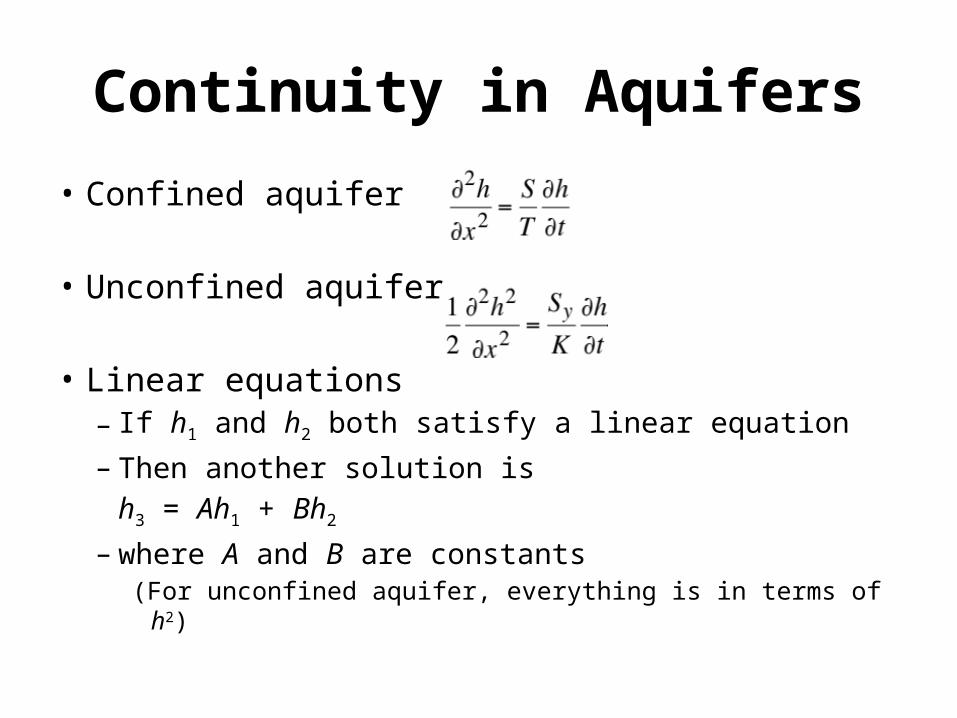
• Confined aquifer
• Unconfined aquifer
• Linear equations– If h1 and h2 both satisfy a linear equation– Then another solution is
h3 = Ah1 + Bh2
– where A and B are constants(For unconfined aquifer, everything is in terms of h2)

Steady Flow to a Well in a Confined Aquifer
2rw
Ground surface
Bedrock
Confined aquifer
Q
h0
Pre-pumping head
Confining Layer
br1
r2
h2h1
hw
Observation wells
Drawdown curve
Q
Pumping well
Point of interest (x,y) Well at = (xw,yw)
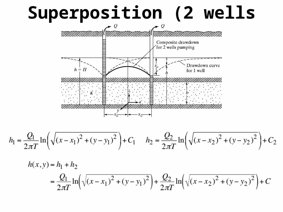
Superposition (2 wells pumping)

Superposition (n Wells pumping)
1r2r
3r
1Q
2Q
3Q
),(11yx
),(33yx
),(22yx
),( yx

Steady Flow to a Well in an Unconfined Aquifer
2rw
Ground surface
Bedrock
Unconfined aquifer
Q
h0
Pre-pumping Water level
r1
r2
h
2h1
hw
Observation wells
Water Table
Q
Pumping well

Example
x
y
1r 2rQ Q
),( yx
oH

ExampleQ = 2x10⁻² m3/s, T = 5x10⁻³ m2/s, Ho = 25 m, rw = 0.25 m
x
y
600 m
1r 2rQ Q
)0,25(
),( yx
)0,25(o
H
mC 9.201
mC 9.202

Example• How much does the pumping in
well 2 affect the head in well 1?
• With both wells pumping
• With only Well 1 pumping
• Difference = 1.54 m
x
Q Q
)0,25(
),( yx
)0,25(

Superposition (n Wells pumping)
1r2r
3r
1Q
2Q
3Q
),(11yx
),(33yx
),(22yx
),( yx
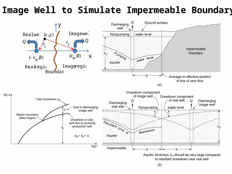
Image Well to Simulate Impermeable Boundary
x
Q
wellImage
)0,(wx
),( yx
)0,(wx
Q
wellReal
1r 2
r
region Real region Image
y
Boundary
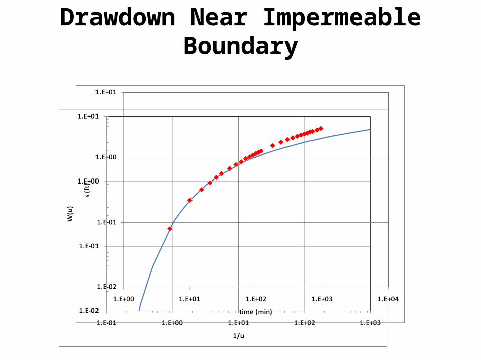
Drawdown Near Impermeable Boundary
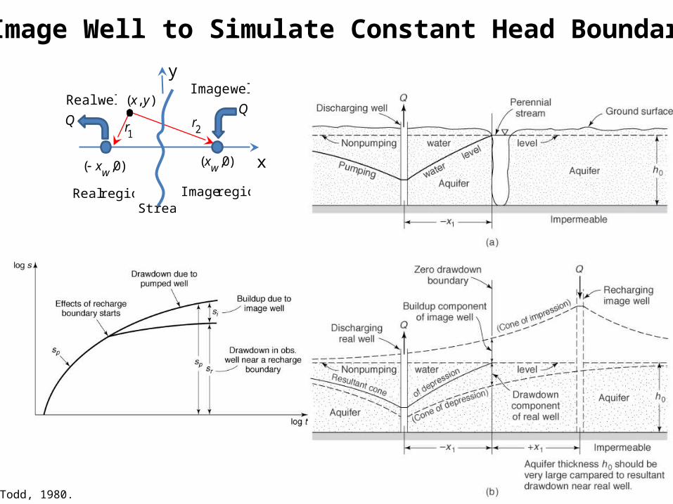
Todd, 1980.
Image Well to Simulate Constant Head Boundary
x
Q
wellImage
)0,(wx
),( yx
)0,(wx
Q
wellReal
1r 2
r
region Real region Image
y
Stream
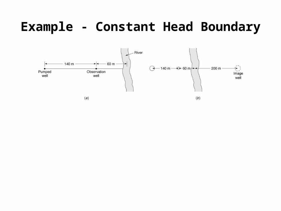
Example - Constant Head Boundary
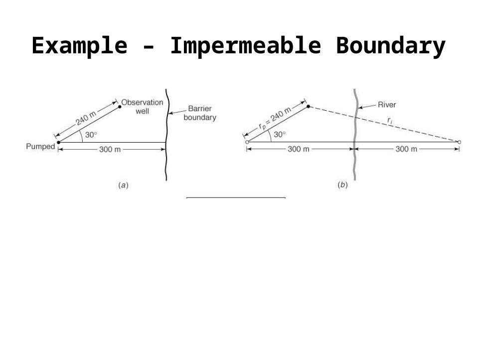
Example – Impermeable Boundary

Multiple Well Systems
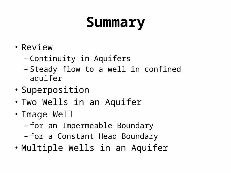
Summary
• Review– Continuity in Aquifers– Steady flow to a well in confined aquifer
• Superposition• Two Wells in an Aquifer• Image Well
– for an Impermeable Boundary– for a Constant Head Boundary
• Multiple Wells in an Aquifer

Well 1 pumping alone
Well 2 pumping alone
Both wells pumping together