Bound exciton and donor–acceptor pair recombinations in ZnO · 2008-05-30 · exciton...
30
phys. stat. sol. (b) 241, No. 2, 231– 260 (2004) / DOI 10.1002/pssb.200301962 © 2004 WILEY-VCH Verlag GmbH & Co. KGaA, Weinheim Feature Article Bound exciton and donor–acceptor pair recombinations in ZnO B. K. Meyer *, 1 , H. Alves 1 , D. M. Hofmann 1 , W. Kriegseis 1 , D. Forster 2 , F. Bertram 2 , J. Christen 2 , A. Hoffmann 3 , M. Straßburg 3 , M. Dworzak 3 , U. Haboeck 3 , and A. V. Rodina 3, 4 1 I. Physics Institute, Justus Liebig University Giessen, Heinrich-Buff-Ring 16, 35392 Giessen, Germany 2 Otto-von-Guericke University Magdeburg, Universitätsplatz 2, 39106 Magdeburg, Germany 3 Technical University Berlin, Solid State Physics Institute, Hardenbergstr. 36, 10623 Berlin, Germany 4 A.F. Ioffe Physico-Technical Institute, RAS, 194021 St. Petersburg, Russia Received 18 September 2003, revised 3 December 2003, accepted 8 December 2003 Published online 27 January 2004 PACS 61.72.Vv, 71.55.Gs, 76.30.Da, 76.70.Dx, 78.20.Ls, 78.55.Et The optical properties of excitonic recombinations in bulk, n-type ZnO are investigated by photolumines- cence (PL) and spatially resolved cathodoluminescence (CL) measurements. At liquid helium temperature in undoped crystals the neutral donor bound excitons dominate in the PL spectrum. Two electron satellite transitions (TES) of the donor bound excitons allow to determine the donor binding energies ranging from 46 to 73 meV. These results are in line with the temperature dependent Hall effect measurements. In the as-grown crystals a shallow donor with an activation energy of 30 meV controls the conductivity. Anneal- ing annihilates this shallow donor which has a bound exciton recombination at 3.3628 eV. Correlated by magnetic resonance experiments we attribute this particular donor to hydrogen. The Al, Ga and In donor bound exciton recombinations are identified based on doping and diffusion experiments and using secon- dary ion mass spectroscopy. We give a special focus on the recombination around 3.333 eV, i.e. about 50 meV below the free exciton transition. From temperature dependent measurements one obtains a small thermal activation energy for the quenching of the luminescence of 10 ± 2 meV despite the large localiza- tion energy of 50 meV. Spatially resolved CL measurements show that the 3.333 eV lines are particularly strong at crystal irregularities and occur only at certain spots hence are not homogeneously distributed within the crystal contrary to the bound exciton recombinations. We attribute them to excitons bound to structural defects (Y-line defect) very common in II–VI semiconductors. For the bound exciton lines which seem to be correlated with Li and Na doping we offer a different interpretation. Li and Na do not introduce any shallow acceptor level in ZnO which otherwise should show up in donor – acceptor pair re- combinations. Nitrogen creates a shallow acceptor level in ZnO. Donor – acceptor pair recombination with the 165 meV deep N-acceptor is found in nitrogen doped and implanted ZnO samples, respectively. In the best undoped samples excited rotational states of the donor bound excitons can be seen in low temperature PL measurements. At higher temperatures we also see the appearance of the excitons bound to the B-valence band, which are approximately 4.7 meV higher in energy. © 2004 WILEY-VCH Verlag GmbH & Co. KGaA, Weinheim 1 Introduction ZnO offers some fascinating properties which have put this II–VI semiconductor into renewed interest. A well established fact is that the free exciton binding energy amounts to 60 meV [1] which makes the excitons stable at room temperature. This binding energy increases further in ZnMgO/ZnO/ZnMgO * Corresponding author: e-mail: [email protected], Tel.: 0049 641 33100, Fax: 0049 641 33119
Transcript of Bound exciton and donor–acceptor pair recombinations in ZnO · 2008-05-30 · exciton...

phys. stat. sol. (b) 241, No. 2, 231–260 (2004) / DOI 10.1002/pssb.200301962
© 2004 WILEY-VCH Verlag GmbH & Co. KGaA, Weinheim
Feature Article
Bound exciton and donor–acceptor pair recombinations in ZnO
B. K. Meyer*, 1, H. Alves1, D. M. Hofmann1, W. Kriegseis1, D. Forster2, F. Bertram2, J. Christen2, A. Hoffmann3, M. Straßburg3, M. Dworzak3, U. Haboeck3, and A. V. Rodina3, 4 1 I. Physics Institute, Justus Liebig University Giessen, Heinrich-Buff-Ring 16, 35392 Giessen, Germany 2 Otto-von-Guericke University Magdeburg, Universitätsplatz 2, 39106 Magdeburg, Germany 3 Technical University Berlin, Solid State Physics Institute, Hardenbergstr. 36, 10623 Berlin, Germany 4 A.F. Ioffe Physico-Technical Institute, RAS, 194021 St. Petersburg, Russia
Received 18 September 2003, revised 3 December 2003, accepted 8 December 2003 Published online 27 January 2004
PACS 61.72.Vv, 71.55.Gs, 76.30.Da, 76.70.Dx, 78.20.Ls, 78.55.Et
The optical properties of excitonic recombinations in bulk, n-type ZnO are investigated by photolumines-cence (PL) and spatially resolved cathodoluminescence (CL) measurements. At liquid helium temperature in undoped crystals the neutral donor bound excitons dominate in the PL spectrum. Two electron satellite transitions (TES) of the donor bound excitons allow to determine the donor binding energies ranging from 46 to 73 meV. These results are in line with the temperature dependent Hall effect measurements. In the as-grown crystals a shallow donor with an activation energy of 30 meV controls the conductivity. Anneal-ing annihilates this shallow donor which has a bound exciton recombination at 3.3628 eV. Correlated by magnetic resonance experiments we attribute this particular donor to hydrogen. The Al, Ga and In donor bound exciton recombinations are identified based on doping and diffusion experiments and using secon-dary ion mass spectroscopy. We give a special focus on the recombination around 3.333 eV, i.e. about 50 meV below the free exciton transition. From temperature dependent measurements one obtains a small thermal activation energy for the quenching of the luminescence of 10 ± 2 meV despite the large localiza-tion energy of 50 meV. Spatially resolved CL measurements show that the 3.333 eV lines are particularly strong at crystal irregularities and occur only at certain spots hence are not homogeneously distributed within the crystal contrary to the bound exciton recombinations. We attribute them to excitons bound to structural defects (Y-line defect) very common in II–VI semiconductors. For the bound exciton lines which seem to be correlated with Li and Na doping we offer a different interpretation. Li and Na do not introduce any shallow acceptor level in ZnO which otherwise should show up in donor–acceptor pair re-combinations. Nitrogen creates a shallow acceptor level in ZnO. Donor–acceptor pair recombination with the 165 meV deep N-acceptor is found in nitrogen doped and implanted ZnO samples, respectively. In the best undoped samples excited rotational states of the donor bound excitons can be seen in low temperature PL measurements. At higher temperatures we also see the appearance of the excitons bound to the B-valence band, which are approximately 4.7 meV higher in energy.
© 2004 WILEY-VCH Verlag GmbH & Co. KGaA, Weinheim
1 Introduction
ZnO offers some fascinating properties which have put this II–VI semiconductor into renewed interest. A well established fact is that the free exciton binding energy amounts to 60 meV [1] which makes the excitons stable at room temperature. This binding energy increases further in ZnMgO/ZnO/ZnMgO
* Corresponding author: e-mail: [email protected], Tel.: 0049 641 33100, Fax: 0049 641 33119

232 B. K. Meyer et al.: Bound exciton and donor–acceptor pair recombinations in ZnO
© 2004 WILEY-VCH Verlag GmbH & Co. KGaA, Weinheim
quantum wells [2]. One of the driving forces is the ability to fabricate heterostructures [3] and to tune the band gap of ZnO from 3.3 eV (at room temperature) to 4 eV by alloying with Mg and to 2.9 eV for the ZnCdO alloys [4]. Quantum wells are of type I [5] thus ideal for opto-electronic devices which need electrical and optical confinement. ZnO is radiation hard [6], thus electronic devices may operate in satellites circling in low earth orbits. With a band gap of 3.3 eV ZnO is a solar blind material and many applications such as transparent front electrodes in solar cells make use of this fact. While majority, n-type carrier devices can be realized such as photodetectors, Schottky-diodes and sensors the important market of light emitting devices (LED, LD) is not yet accessible as long as the acceptor doping problem is not solved. Already until the 70th different ways were tested such as doping in the melt, in the vapor phase, by diffusion, and implantation to bring impurities in a controlled way into ZnO [7, 8]. A focus was on group-I elements [8], Li and Na may induce shallow acceptor states as in other II–VI semiconductors such as ZnTe and ZnSe. However, Li-doping has always been suspicious, since Li-ion is very mobile and might also locate at interstitial sites acting as a shallow donor and compensate the acceptor action (self compensation). Besides self compensation, limitations in the solubility may prohibite p-type conduction going along with the magnitude of the acceptor binding energy. In wide band gap semiconductors with the averaged value of the hole polaron masses around *
hm ≈ 0.7 m0 and static dielectric constants around 7 binding energies of the acceptors between 200 and 300 meV can be expected. At room temperature only a small fraction of the total acceptor concentration is available as free holes. For opto-electronic devices 1017–1018 holes/cm–3 are usually necessary in the p-doped regions, thus a low solubility will be a severe obstacle. Another aspect is, depending on ionic or covalent radii, impurities may not be incorporated on the prefered lattice sites. Last but not least intrinsic defects such as the cation and anion vacancies which are double acceptors and donors in ZnO, respectively, may form complexes with the dopant atoms and may convert p- to n-type conduction. Reports on p-type conduction in ZnO have been rare, could not be reproduced, or are questionable especially if the influence of the substrate on which the thin films were grown could not be decoupled (integrating Hall-effect) [9–14]. ZnO is a brilliant emitter and it is not wondering that numerous photoluminescence investigations exist of the near band gap recombinations. In high quality bulk crystals the luminescence line width of excitonic recombination is as narrow as 40 µeV and many fine spectroscopic details have been observed. However, a convergent picture as to the origin has not emerged. This starts with the ordering of the valence bands and the fine structure of free excitons (general properties of ZnO can be found in Table 1). ZnO is a direct band gap semiconductor which crystallizes in the wurtzite symmetry. The valence band is split by crystal field and spin orbit interaction into three states named A, B and C (see Fig. 1). The symmetry of the upper valence subband (A-subband) in ZnO has been the subject of controversy (Γ9 or Γ7 character) for more than 40 years [1, 15–24]. Based on the polarization properties of the free exciton transitions, most of the authors assume that the symmetry of the A-valence subband is Γ7 [1, 15, 17–21, 25–27]. In contradiction to that, the most recent studies of the free exciton oscillator strengths [22] and the most recent magneto-optical studies of the free A exciton transition fine structure [23] were interpreted with the assumption of Γ9 symmetry for the valence band maximum. A more elaborated theo-retical analysis of the magneto-optic exciton fine structure made in Ref. [24] has allowed to explain the experimental data of Ref. [23] still assuming Γ7 symmetry of the upper A valence band in wurtzite ZnO. In this paper we will give additional evidence for the Γ7 symmetry of the upper A valence subband based on the detailed magneto-optical studies of the ionised donor bound exciton complex. At low cryogenic temperatures bound exciton emission is the dominant radiative channel, whereas at higher temperatures free exciton emission usually takes over. Up to eleven excitonic recombinations where excitons bind to neutral donors and/or acceptors have been observed [1, 8, 15, 29, 30], however, the chemical nature of the donor and acceptor species remained to be determined. In bulk ZnO crystals the free exciton is observed at about 3.377 eV. The emission at 3.367 eV is commonly assigned to ion-ised donor bound excitons [29] and the neutral donor bound excitons are positioned between 3.3628 and 3.359 eV. Finally, bound excitons previously attributed to the Na and Li acceptors [8] occur at 3.356 and

phys. stat. sol. (b) 241, No. 2 (2004) / www.pss-b.com 233
© 2004 WILEY-VCH Verlag GmbH & Co. KGaA, Weinheim
Table 1 Band structure related properties of wurtzite ZnO [93] [24 and refs. therein].
EgA –3.437 eV (T = 1.6 K) EAB –4.9 meV EBC –43.7 mev EgB –3.4425 eV EgC –3.4813 eV
Temperature dependence of the band gap up to 300 K
Eg (T) = Eg (T = 0) 4 25.05 10
900
T
T
−
⋅ ⋅
−
Dielectric constants ε (0) ⊥ c
–7.8
ε (0) || c –8.75 ε (∞ ) ⊥ c –3.7 ε (∞ ) || c –3.75
Electron effective (polaron) mass in units of m0 em∗ || –0.28
em∗ ⊥ –0.24
Hole effective mass in units of m0
hm∗ (A) –0.59 || = ⊥
hm∗ (B) –0.59 || = ⊥
Crystal field splitting in meV ∆cf
– –41.7
Spin orbit splitting in meV ∆so
–8.0
Electron g-values ge
|| –1.956 – 1.958
eg⊥ –1.955 – 1.956
Hole g-values gA
|| –2.45 g A
⊥ –0.09 gB
|| –1.5 gB⊥ –0
gC|| –1.95
gC⊥ –1.91
Landé g-factors for the hole participating in the 1S exitons gA
|| (1S) –1.32 gB
|| (1S) –3.04 gC
|| (1S) –1.06
Phonon modes at T = 300 K in cm–1 E low
2 –101 E high
2 –437 TO (A1) –380 LO (A1) –574 TO (E1) –591

234 B. K. Meyer et al.: Bound exciton and donor–acceptor pair recombinations in ZnO
© 2004 WILEY-VCH Verlag GmbH & Co. KGaA, Weinheim
ZnO
EG=3.4376 eVT=4.2K
∆∆∆∆EBC
=43.7 meV
∆∆∆∆EAB
=4.9 meV
ΓΓΓΓ9999[B]
ΓΓΓΓ7777[C]
ΓΓΓΓ7777[A]
ΓΓΓΓ7777
E
k 3.353 eV, respectively (for line positions see Table 2). There is considerable dispute on these assign-ments. Based on magneto-photoluminescence experiments Gutowski et al. [25] attributed all recombina-tions from I5 to I10 to acceptor bound excitons contradicting published experiments which showed that I4 to I8 are neutral donor bound excitons and to the magneto-absorption data of Loose et al. [27]. Recently, in undoped films grown by MBE a new line at 3.332 eV was reported (ZnO on CaF2 (111)) [31] which is quite close to the 3.335 eV line for ZnO on a-plane sapphire presented by Kato et al. [32] (taking into
Table 2 Free and bound exciton recombinations and related properties.
line wavelength (nm)
energy (eV)
localisation energy (meV)
two-electron-satellite separation (2Pxy – 1S) (meV)
donor binding energy (meV)
chemical identity
AL* 367.12 3.3772
AT* 367.26 3.3759
I0 367.63 3.3725 3.4 I1 367.71 3.3718 4.1 I1a 368.13 3.3679 8.0 I2
** 368.19 3.3674 8.5 I3
** 368.29 3.3665 9.4 I3a 368.34 3.3660 9.9 I4 368.34 3.3628 13.1 34.1 46.1 H I5 368.86 3.3614 14.5 I6 368.92 3.3608 15.1 38.8 51.55 Al I6a 368.96 3.3604 15.5 40.4 53 I7 369.01 3.3600 15.9 I8 369.03 3.3598 16.1 42.1 54.6 Ga I8a 369.08 3.3593 16.6 I9 369.37 3.3567 19.2 50.6 63.2 In I10 369.76 3.3531 22.8 60.2 72.6 I11 370.28 3.3484 27.5
* AL and AT are the longitudinal and transversal free A-exciton states. AT is the reference for the determination of the bound excition localisation energy. ** I2 and I3 are assigned to ionised donor bound exciton recombinations.
Fig. 1 Band structure and symmetries of hexagonal ZnO. The splitting into three valence bands (A, B, C) is caused by crystal field and spin-orbit splitting.

phys. stat. sol. (b) 241, No. 2 (2004) / www.pss-b.com 235
© 2004 WILEY-VCH Verlag GmbH & Co. KGaA, Weinheim
account the different strain situations in the films). Both groups [31, 32] assigned the recombination as caused by excitons bound to neutral acceptors. Thonke et al. [33] observed transitions at 3.32, 3.33 and 3.333 eV in bulk, nominally undoped ZnO, and assigned it to two-electron satellite transitions of the neu-tral donor bound exciton lines. Things started to become even more complicated when Look et al. [10] reported on the optical properties of MBE grown ZnO films doped with Nitrogen claiming the electrical properties (according to the authors the films are p-type with free hole concentrations of 9 × 1016 cm–3 at room temperature) are consistent with the photoluminescence data. A line at 3.315 eV was attributed to a neutral acceptor (nitrogen on an oxygen site) bound exciton transition. It was, therefore, our interest to gain further insight into the nature of those recombinations using temperature dependent photolumines-cence as well as spatially resolved cathodoluminescence. Our conclusion is that the lines sharp at around 3.333 eV is of excitonic nature and show most of the established features of the Y-line (excitons bound to structural defects) recombination commonly be seen in ZnSe and ZnTe [34, 35]. Other lines between 3.31 and 3.33 eV belong to two-electron satellite transitions of the neutral donor bound exciton recombinations [33, 36]. Nitrogen doping in ZnO induces a donor–acceptor pair band [37] with a zero phonon line at 3.235 eV, a corresponding nitrogen acceptor bound exciton could not be identified so far. Neutral donor bound exciton recombination seems to be the prevalent emission channel.
2 Experimental details
The photoluminescence was measured in a temperature variable Oxford cryostat (1.5–300 K). The sam-ples were excited by the 325 nm line of a HeCd laser (30 mW) and the emission was detected after dis-persion with a 1 m Jobin Yvon monochromator by a photomultiplier (Hamamatsu R375, 160–850 nm). Standard lock-in technique was employed. Low temperature cathodoluminescence experiments were performed in a fully computer-controlled modified scanning electron microscope (spatial resolution better than 100 nm) yielding CL linescan and CL wavelength images (CLWI). Variable tempera- ture Hall-effect measurements were conducted with a computer controlled system including a Keithley
Table 3 Details about the ZnO samples used in the current investigations.
sample provider doping main trace impurity comments
# 1
Eagle-Picher (E-P) as grown
nominally undoped hydrogen1 free carrier concentration
1.2 × 1017 cm–3 at 300 K activated by 23 ± 5 meV
# 2
E-P annealed, at 600 °C, 30 min, N2
nominally undoped – –
# 3
E-P annealed, at 850 °C, 30 min, N2
nominally undoped gallium1 aluminium2
free carrier concentration 7 × 1016 cm–3 at 300 K activated by 55 ± 5 meV
# 4 SEMI-ELEMENT INC. Vapor Phase growth (VPG)
nominally undoped aluminium2 –
# 5 VPG, University Erlangen
Na indium3 deep NaZn acceptor seen in EPR* and ODMR
# 6 VPR, University Erlangen
Li indium3 deep LiZn acceptor seen in EPR* and ODMR
# 7 Crystec
nominally undoped lithium1 deep LiZn acceptor seen in EPR*
1 based on EPR/ENDOR investigations. 2 based on SIMS investigations. 3 based on photoluminescence investigations. * under band to band excitation at T = 50 K.

236 B. K. Meyer et al.: Bound exciton and donor–acceptor pair recombinations in ZnO
© 2004 WILEY-VCH Verlag GmbH & Co. KGaA, Weinheim
2.1 2.2 2.3 2.4 2.5 2.6 2.7 2.8 2.9 3.0 3.1 3.2 3.3 3.4
1x10⁻⁵
1x10⁻⁴
10-3
10-2
10-1
100
ELO
DAxP-2xE
LO
DAxP-E
LO
DAxP
PL
Inte
nsi
ty(a
.u)
Energy (eV)
T = 4.2K
Fig. 2 Photoluminescence spectrum of bulk ZnO showing excitonic, donor acceptor pair (DAP) and deep level emission. The corresponding phonon replica with longitudinal optical phonons (LO) are indi-cated (HeCd excitation).
source-measurement unit as constant current source and Keithley Hall-effect card (type 7065). The Hall voltage was measured with a Keitley electrometer (type 617). Samples of 5 × 5 mm2 size had In ohmic contacts in the four corners (Van der Pauw geometry). The contacts showed ohmic behaviour over the whole temperature range. The samples could be measured from 4.2 up to 400 K in an Oxford He cry-ostate. We used state of the art bulk ZnO crystals, O-face, from Eagle-Picher, CRYSTEC and ZnO single crystals (see Table 3) grown from the vapor phase without or with intentional doping (Na, Li). For de-tails see Tomzig et al. [8]. Magneto-optical properties of the excitons are examined by polarizazion dependent photolumines-cence at low temperatures. The measurements were performed in Faraday and Voigt configurations as well as for different angles between the magnetic field and the c-axis of the crystal.
3 Experimental results
3.1 Undoped ZnO: general features
The luminescence from bulk ZnO (#1, see Table 3 for more details) extends from the band edge to the green/orange spectral range (an overview spectra is shown in Fig. 2). Very common is a broad band centred around 2.45 eV extending from the blue into the green range. The lines dominating the spectra originate from bound exciton (BE) recombinations (excitons bound to neutral donors (D0X) and/or ac-ceptors (A0X)) followed by longitudinal optical (LO) phonon replicas with an energy separation of 72 meV. In some samples a donor-acceptor-pair (DAP) transition is found, the chemical identity of the acceptor Ax is unknown. The transition energy is around 3.22 eV again followed by phonon replicas (see Fig. 2). There is no definite assignment of the bound exciton recombinations to a specific donor or ac-ceptor, they are numbered I0 to I11 in the early work of Reynolds et al. [29]. The prominent lines in the bulk ZnO are the bound excitons positioned at 3.3628, 3.3608 and 3.3598 eV (labeled in Fig. 3 as I4, I6.8). At 3.357 eV another bound exciton (I9) can also be observed. The free exciton emission with the A-valence band (FXA) positioned at 3.375 eV can already be seen. At lower energies from 3.34 to 3.31 eV further recombination lines appear. It is the region where one can expect the two-electron satel-lite (TES) recombination lines of the neutral donor bound excitons. During the recombination of an exci-ton bound to a neutral donor the donor final state can be the 1s state (normal D0X line) or the 2s, 2p state (TES-line). The energetic distance between the D0X and its TES is consequently the difference between the donor energies in the 1s and 2p states, which is 3
4 of the donor binding energy (ED) in the hydrogenic effective-mass-approach (EMA). Therefore, by determining the position of the TES the related donor

phys. stat. sol. (b) 241, No. 2 (2004) / www.pss-b.com 237
© 2004 WILEY-VCH Verlag GmbH & Co. KGaA, Weinheim
3.31 3.32 3.33 3.34 3.35 3.36 3.37 3.38
10-3
10-2
10-1
100T=4.2K
I9
I6...8
I4
FXA
TES
PL
Inte
nsi
ty(a
.u
)
Energy (eV) binding energy is obtained with high precision including further corrections (see Sect. 3.5). Recombina-tions in the TES region were also observed earlier [33, 36]. Our first interest was to study the thermal stability of the different impurities connected to the bound exciton recombinations. Bulk ZnO samples were cut into pieces, and subsequently annealed in N2 at-mosphere for 30 minutes from 600 to 850 °C in steps of 50 °C. The main results of these treatments are shown in Fig. 4. Let us first concentrate on the effects observed for the bound excitons (spectra on the
3.356 3.360 3.364 3.368
3.356 3.360 3.364 3.368
3.356 3.360 3.364 3.368
3.316 3.320 3.324 3.328 3.332
3.316 3.320 3.324 3.328 3.332
3.316 3.320 3.324 3.328 3.332
PL
inte
ns
ity(a
.u)600˚C ann
PL
inte
nsi
ty(a
.u)
as-grown
PL
inte
nsi
ty(a
.u)
Energy (eV)
850˚C ann
PL
inte
nsi
ty(a
.u)
as-grown
TES(I8) TES(I
6/6a) TES(I
4) DBX I
9I8
I6/6a I
4
PL
inte
nsi
ty(a
.u)
600˚C ann
Energy (eV)
PL
inte
nsi
ty(a
.u)
850˚C ann
Fig. 4 Photoluminescence spectra in the bound exciton region of a bulk ZnO crystal in the as-grown state and after annealing in N2 atmosphere at 600 and 850 °C for 30 minutes. The right side shows the excitonic range, the left side the corresponding two-electron-satellite (TES) range (T = 4.2 K, HeCd exci-tation).
Fig. 3 Photoluminescence spectrum in the exci-tonic range. FXA is the transversal free exciton, I4 to I9 are bound exciton lines. The region where the two-electron-satellite (TES) transitions occur is indicated (HeCd excitation).

238 B. K. Meyer et al.: Bound exciton and donor–acceptor pair recombinations in ZnO
© 2004 WILEY-VCH Verlag GmbH & Co. KGaA, Weinheim
3.356 3.360 3.364 3.368 3.37210-3
10-2
10-1
100
3.315 3.320 3.325 3.330 3.335 3.340
0.05
0.10
0.15
0.20
0.25ZnO bulkZnO:Al
I9
I8
I4
I6/6a
PL
Inte
nsi
ty(a
.u
.)
Energy (eV)
TES (I6/6a
)
PL
Inte
nsi
ty(a
.u
.)
Energy (eV)
Fig. 5 Comparison of the PL-spectra of an as-grown bulk ZnO and a ZnO:Al sample. In the inset the TES transitions are shown (T = 4.2 K, HeCd excitation).
right in Fig. 4). For an annealing temperature of 600 °C the 3.3628 eV line (I4) decreases in intensity by a factor of 20, annealing at 850 °C results in its complete disappearance. The other two donor bound exci-tons (3.3608 and 3.3597 eV) gain in intensity upon the first annealing and then remain constant. The bound exciton line at 3.357 eV remains uneffected. These results show that the donor causing the 3.3628 eV line is easily removed at annealing temperatures above 600 °C, while the other species in-volved in the other BE recombinations seem to be quite stable. The spectra of Fig. 4 (left side) show the luminescence in the TES range. Four transitions are marked by the dashed lines. The one at 3.333 eV increases in intensity by a factor of 100 after annealing. There-fore its behaviour cannot be related to any of the four donor bound excitons. The nature of this line will be discussed below. The other three lines seem to follow well the behavior of the four donor bound exci-tons, the one positioned at 3.33 eV is only observed on the as-grown sample, like I4. More, the intensity ratio between this line and the two at 3.323 and 3.318 eV is basically the same as between the I4 and the I6/6a, I8. In the spectra of the annealed samples one can also see that the behaviour of the 3.323 and the 3.318 eV lines reflect well the behaviour of the second and third bound excitons. Note also that upon annealing they are much better resolvable, most likely connected to the reduction in the free carrier den-sity (see below). From these results we attribute the 3.33, 3.323 and 3.318 eV lines to the TES complexes of the three donor bound excitons I4, I6/6a, I8, respectively. We performed Hall effect measurements on the same crystals. The concentrations of the donors and their “binding” energies (see Table 3) were ob-tained by the procedure outlined by Look et al. ([38] and Refs. therein). It is evident that upon annealing the free carrier density drops from 1 × 1017 cm–3 to around 6 × 1016 cm–3 (850 °C annealing). The analy-sis yields that the donor with a binding energy around 30 meV anneals out and that the donors with bind-ing energies around 55 meV control the free carrier density of the annealed samples. Taking the experi-mental uncertainty into account, the Hall results support our PL observations that the donor related to the 3.3628 eV line is thermally instable (see also Ref. [39]). To clarify the nature of the recombination line at 3.333 eV marked in Fig. 4 by DBX we looked into different undoped ZnO crystals grown from the vapor phase at the University Erlangen and by SEMI-ELEMENT. INC. In none of the undoped and Na- or Li-doped crystals this particular transition is ob-served. As an example we show the luminescence of the sample #4 (see Fig. 5). It has only one promi-nent bound exciton recombination at the position of I6/6a and the only feature we can see is the respective TES at 3.32 eV. Thus the transition at 3.333 eV which gains in intensity upon annealing must be of dif-ferent origin.

phys. stat. sol. (b) 241, No. 2 (2004) / www.pss-b.com 239
© 2004 WILEY-VCH Verlag GmbH & Co. KGaA, Weinheim
0 50 100 150 20010-3
10-2
10-1
100
DBX
I6/6a
PL
Inte
nsi
ty(a
.u
.)
1000/T (K-1)
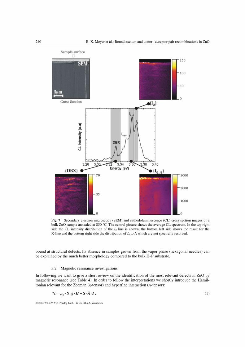
The recombination at 3.333 eV seems to be of excitonic origin, it disapears rather quickly upon in-creasing the temperature. In a temperature dependent study the activation energy for the luminescence quenching could be determined and is in Fig. 6 compared with the respective activation energy of I6/6a. Both recombinations show practically within the experimental error the identical activation energy of 10 meV despite the fact that I6/6a is 14.5 meV and the doublet at 3.333 eV is appr. 50 meV below the free A-exciton transition energy. These findings remind very much on the Y-lines observed first by Dean et al. in ZnSe [40], later observations were made by Naumov et al. [34] and Fujii et al. [41] in ZnTe. Note that the 3.41 eV emission in GaN also belongs to this class of recombination type [42]. Dean [40] proposed a model for the origin of the Y-line to be caused by localized recombinations at extended de-fects such as dislocation loops. To gain further insight into the nature of the 3.333 eV lines we performed spatially resolved cathodoluminescence measurements on a 20 × 20 µm2 scale on an undoped ZnO film grown on GaN-templates. As shown in Refs. [42, 44] the shallow bound exciton recombinations are randomly distributed (plan view CL of the layer surface) the emission monitored in wavelength interval between 371.6 and 373.9 nm i.e. the 3.333 eV bands is spot like and localized (see Fig. 5 in Ref. [43]) and appears to be correlated with irregularities in the growth (see the CL imaging (CLI)). A similar study was performed on ZnSe by Myhajlenko et al. [35] and it was concluded that the dislocations act as radia-tive recombination centers. From the fact that the bound excitons are randomly distributed whereas the 3.333 eV lines occur spot like it is clear that no correlation as to a common origin of the two recombina-tions exists (e.g. different TES). In the heteroepitaxial films we can of course expect that lattice-mismatch defects may influence the radiative recombination as was the case for the layers grown by MOCVD ZnSe on GaAs or Ge and ZnTe on GaAs and GaSb ([34] and Refs. therein). We, therefore, performed CL measurements on the bulk ZnO (#1) annealed at 850 °C where the X-line has considerable strength. The I6 to I8 recombinations (which are not spectrally resolved) dominate the average CL spec-trum (see central part in Fig. 7). The luminescence coming from I2 and I6 to I8 recombinations is homo-geneously distributed in the sample (right side of Fig. 7). Only near the sample surface an increase in the luminescence intensity is observed. The SEM image shows the existence of a thin surface layer at the sample surface. This thin layer is probably caused by the final polishing/etching process. The lumines-cence of the DBX-line is much more localized and almost spot like (see bottom left side of Fig. 7). This rather fast decay time points to excitonic nature which is also supported from the temperature dependent PL measurements (see Fig. 6). In a recent report on homoepitaxial growth of ZnO on ZnO substrates we used high resolution X-ray diffraction to determine the properties of the substrate [45]. The substrate showed a strong mosaicity, had a columnar structure, the columns being tilted with respect to each other. In a reciprocal space map discrete spikes from individual crystallites could be distinguished. From the CL measurements on bulk and epitaxial samples it appears that the DBX-line is mainly located in areas of crystal irregularities. We, therefore, come to conclusion that the DBX-line, similar to the Y and Z series observed by Dean in ZnSe [40] and the 3.41 eV recombination in GaN [42], is related to excitons
Fig. 6 Thermally activated luminescence quench-ing of the I5/6 neutral donor bound exciton recom-bination (full circles) and of the recombination at 3.33 eV (full squares). The activation energy is obtained by a fit to the data (drawn lines).
240 B. K. Meyer et al.: Bound exciton and donor–acceptor pair recombinations in ZnO
© 2004 WILEY-VCH Verlag GmbH & Co. KGaA, Weinheim
Fig. 7 Secondary electron microscopy (SEM) and cathodoluminescence (CL) cross section images of a bulk ZnO sample annealed at 850 °C. The central picture shows the average CL spectrum. In the top right side the CL intensity distribution of the I2 line is shown; the bottom left side shows the result for the X-line and the bottom right side the distribution of I6 to I8 which are not spectrally resolved.
bound at structural defects. Its absence in samples grown from the vapor phase (hexagonal needles) can be explained by the much better morphology compared to the bulk E-P substrate.
3.2 Magnetic resonance investigations
In following we want to give a short review on the identification of the most relevant defects in ZnO by magnetic resonance (see Table 4). In order to follow the interpretations we shortly introduce the Hamil-tonian relevant for the Zeeman (g-tensor) and hyperfine interaction (A-tensor):
B g Aµ= ⋅ ⋅ ⋅ + ⋅ ⋅S H S I��H . (1)

phys. stat. sol. (b) 241, No. 2 (2004) / www.pss-b.com 241
© 2004 WILEY-VCH Verlag GmbH & Co. KGaA, Weinheim
Table 4 Magnetic resonance parameters and defect assignments
spin g-values hyperfine interaction finestructure defect assignment reference
S = 12 g|| = 1.953
g⊥ = 1.955
not observed shallow donor [46]
S = 12 g|| = 1.957
g⊥ = 1.956
not observed shallow donor [47]
S = 12 g = 1.956 not observed shallow halogen donors [47]
S = 12 g|| = 1.957
g⊥ = 1.956
A(115In) = 36.6 G A(69Ga) = 4.2 G A(69Ga, 72Ga) = 6.7 G
shallow In donor shallow Ga donor shallow Ga donor
[48, 49] [48] [50]
S = 12 g|| = 1.9569
g⊥ = 1.9552
A(1H) = 1.4 MHz shallow H donor [52]
S = 12 g|| = 1.9945
g⊥ = 1.9960
A|| = 57.34 MHz A
⊥ = 42.3 MHz
axial center Axx = 76.6 MHz, Ayy = 75.9 MHz, Azz = 94.8 MHz non-axial center
oxygen vacancy, F+ *
[58] [56, 57] [62, 63]
S = 12 gzz = 2.0038
gyy = 2.018 gxx = 2.0191 g|| = 2.0149 g
⊥ = 2.0134
P-center in [59] zinc-vancancy related di- or trivacancy centers *
[60] [59] [61] [62, 63]
axial at room temperature S = 1
2 gzz = 2.0038 gyg = 2.0018 gxx = 2.0217
zinc-vacancy related *
[59]
S = 1 gzz = 2.0095 gyy = 2.0141 gzz = 2.019
| D | = 1465 MHz | E | = 58 MHz
zinc-vacancy related *
[59] [61] [62, 63]
S = 12 g|| = 2.0028
g⊥ = 2.0253
axial center gzz = 2.004 gyy = 2.0254 gxx = 2.0223
A|| = 0.22 G A
⊥ = 1.81 G
Azz = 0.29 G Axx = 1.8 G = Ayy
hole on an oxygen atom adjacent to a Li-atom; deep Li-acceptor
[47] [64] [65]
non-axial center S = 1
2 g|| = 2.0024 g
⊥ = 2.0298
axial center gzz = 2.0032 gyy = 2.0302 gxx = 2.0241 non-axial center
A|| = 2.89 G A⊥ = 1.58 G Axx = 1.61 G Ayy = 1.42 G Azz = 4.15 G
hole on an oxygen atom adjacent to a Na-atom; deep Na-acceptor
[66]
S = 12 g|| = 1.9953
g⊥ = 1.9633
A|| = 81.3 MHz A
⊥ = 9.5 MHz
deep nitrogen acceptor [69] [50, 70]
S = 1 g|| = 1.971 g
⊥ = 2.0224
g|| = 1.984 g
⊥ = 2.025
D = 0.763 GHz D = 260 × 10–4 cm–1
optical detection of ESR optical detection of ESR oxygen vacancy; F-center
[69] [71]
* (after e– or n0 irradidation)

242 B. K. Meyer et al.: Bound exciton and donor–acceptor pair recombinations in ZnO
© 2004 WILEY-VCH Verlag GmbH & Co. KGaA, Weinheim
For centers having axial symmetry it gives 12( )S =
H = µB [g� Sz Hz + g⊥ (SxHx + SyHy) + A� Sz Iz + A⊥ (SxIx + Sy Iy) . (2)
For S > ½ an additional finestructure interaction can occur given by
H = D⋅ ⋅S S� , (3)
which in the principal axis system leads to
H = 2 2 213[ ( 1)] ( )z x yD S S S E S S− + + − . (4)
S, I: electron spin, nuclear spin, respectively and their components Sx, Sy, Sz, Ix, Iy, Iz;
A� : hyperfine interaction tensor and its components A�, A⊥, Axx, Ayy, Azz; g� : g-tensor and its components g�, g⊥, gxx, gyy, gzz;
D� : fine structure tensor and its components D (axially symmetric part) and E (asymmetry parameter); H: magnetic field. There are many spectroscopic techniques which enable to conclude on the presence of shallow and deep defects in semiconductors such as Hall-effect measurements, secondary ion mass spectroscopy (SIMS), deep level transient spectroscopy (DLTS) etc. However, in many cases they give more a global picture, and the link to the microscopic and chemical properties is in general not possible. Electron spin resonance (ESR) may work very well on the identification of defects but there is no direct correlation to the luminescence properties of bound excitons. We first summarize what is known from ESR, and in Section 3.4 relate some of the shallow donors to certain bound exciton lines. In 1961 Schneider et al. [46] made the first ESR observation on shallow donors in ZnO followed by Kasai in 1962 [47]. The line width varied between 2 to 6 Gauss at 77 K and hyperfine action with the donor nucleus could not be resolved (see Fig. 8 for the ESR spectrum of an aluminum unintentionally doped sample). An important aspect was that the donors are not isolated but the electrons move from site to site by hopping conduction or depending on the concentration form an impurity band [48]. The motional narrowing of the ESR lines will average out the hyperfine interactions and an identification of the donor is not possible. Kasai concluded on the presence of halogen donors by a heat treatment of pure ZnO together with alkali halides [47]. In 1982 a first positive identification of a shallow donor in ZnO was reported by Gonzales et al. [49] using ESR and ODMR (optically detected magnetic resonance). At very long delay times of the donor–acceptor pair recombination in ZnO:Li they detected a ten lines spectrum of the 115In donor (confirmed by optically detected ENDOR). The line width was 21 G considerably larger than in the earlier reports. In the same work first experimental evidence was given for the Ga donor [48, 49], a similar interpretation was used quite recently [50] (see Fig. 8 for the EPR spectrum in a bulk ZnO sample with gallium as trace impurity). In 2002 stimulated by a theoretical work of Van de Walle [51] hydrogen could be identified as a shallow donor too [52]. The “1.96” resonance has been attributed for a long time with the singly ionized charge state of the oxygen vacancy (F+-center) [53–55], although the F+-center could only be detected after electron or neutron irradiation of ZnO [56–58]. As to acceptor related centers (apart from transition metal elements which will not be considered here) three of them were detected again after particle irradiation of undoped ZnO [59–63]. None of them seem to have the properties of an isolated Zn-vacancy, Leutwein et al. [59] presented several arguments in favor of a Zn–O divacancy or even Zn–O–Zn trivacancy both oriented along the c-axis (P-center in Ref. [59]). These interpretations took the support from the observation of Li-related acceptor centers [64] in BeO and ZnO by Schirmer [65] (a first observation was made by Kasai in ZnO powder [47]). Li substitutes for Zn sites and is surrounded by four oxygen neighbors in the first coordination sphere. In the ionic description the Li+ is surrounded by O2– ions. In this configuration it is diamagnetic. The paramagnetic charge state, when a hole is trapped at one the four nearest neighboring sites, is achieved under light illumination with

phys. stat. sol. (b) 241, No. 2 (2004) / www.pss-b.com 243
© 2004 WILEY-VCH Verlag GmbH & Co. KGaA, Weinheim
3440 3450 3460 3470 3480 3490
gD=1.96
∆HWB = 6 Gauß
EP
RIn
tens
ity(a
rn.u
nits
)
Magnetic Field (Gauß)
9 GHz
4.2 K
1 mW
3400 3450 3500
EP
RIn
tens
ity((
arb.
units
)
Magnetic Field (Gauß)
Ga69,71
; I = 3/2
9 GHz22 K20 µW
Fig. 8 Electron paramagnetic resonance (EPR) spectrum of the Al and Ga donor in bulk ZnO.
u.v. light. The spectrum is best seen at temperatures between 50 and 70 K to avoid easy achievable satu-ration. The four sites are, however, not equivalent, the axial position is favored, and the non-axial sites are occupied by thermal excitation. The energy separation is (15 ± 4) meV. The analysis of the Li hyper-fine structure yields that the center is distorted, the Li–O distance increases by about 40% compared to the normal bond distance [65]. The interpretation of the deep Na-center [66] is in analogy to the Li-center. Again there is a strong relaxation, for the axial centers the distance again increases by about 40% whereas for the non-axial centers it is around 20%. Both centers can be observed by optically detected magnetic resonance in the respective shallow donor to deep acceptor recombinations [67, 68]. The esti-mated binding energies were around 800 meV for Li, and around 600 meV for Na. Quite recently pre-sumably another Jahn–Teller distorted deep acceptor center related to nitrogen was observed by Carlos et al. [69] (see Table 4) and Garces et al. [50, 70]. We, therefore, reinvestigated our bulk samples by EPR in order to clarify the role of the shallow do-nors and deep acceptors (as trace impurities V and Mn were found in some samples). Astonishingly, the donor resonance did not appear in all samples cooled down in dark and measured in dark but needed additional u.v. excitation. One exception was sample #4 which showed a very strong donor resonance with the strongest motional averaging effect. The line width was 2G. In such a case there is no chance to identify the donor by EPR. In the Na-doped (#5) sample the donor resonance was visible without illumi-nation at 4.2 K (∆H = 4G). At 50 K the resonance of the Na-acceptor together with the shallow donor can be observed (see Fig. 9 for the EPR spectrum of the axial and non-axial Sodium acceptor together
3300 3320 3340 3360 3380 3400 3420 3440 3460
Shallow donorNaZn
non axialNaZn
axial
LiZn
non axial
LiZn
axial
ES
RIn
ten
sity
(a.
u.)
Magnetic field (Gauss)
Fig. 9 Electron paramagnetic resonance (EPR) spectrum of the deep Na-acceptor together with the shallow donor resonance under HeCd laser-excitation (lower trace) and of the deep Li-acceptor (upper trace).

244 B. K. Meyer et al.: Bound exciton and donor–acceptor pair recombinations in ZnO
© 2004 WILEY-VCH Verlag GmbH & Co. KGaA, Weinheim
3.15 3.20 3.25 3.30 3.3510-4
10-3
10-2
10-1
100
101
I10
I9
I2
DAxP-1LO
DAxP BE-1LO
PL
Inte
nsi
ty(a
.u
.)
Energy (eV) with the shallow donor resonance). In another bulk ZnO (#7) sample the Li-acceptor is seen under light illumination (see Fig. 9). There are again two groups of lines which are caused by the axial and non-axial centers. In this particular sample neither with nor without illumination the donor resonance is ob-servable. Identical behavior was found for the Li-doped sample (#6).
3.3 Na and Li doped ZnO
There were reports in the years 1950 and 1958 that the n-type conductivity (a compilation of the data is found in Ref. [7]) of ZnO can be reduced by the incorporation of monovalent cations such as Li and Cu, and it was the hope that the group-I elements (e.g. Li, Na) substituting for Zn give rise to a (shallow) acceptor. In 1962 Kasai [47] demonstrated using electron paramagnetic resonance (EPR) that Li indeed introduces an acceptor state in ZnO. However, judging from the g-values close to the free electron g-value of 2, and having in mind that the shallow acceptors should have values around 0.7 and 0.1, par-allel and perpendicular to the c-axis, respectively, [24] it was clear that Li introduces a deep acceptor state. This was later confirmed by optically detected magnetic resonance experiments [48, 49]. The Li acceptor level would be at least 500 meV above valence band and radiative recombination occurs with the deep state as demonstrated by ODMR. A very similar observation was made quite recently in our laboratory on Na-doped ZnO [68]. As with Li, Na introduces a deep acceptor. It was, therefore, our in-terest to look into the photoluminescence of Li- and Na-doped crystals whether in addition to the deep centers giving rise to donor-acceptor-pair recombinations in the green, yellow spectral range also shallow centers are present. Figure 10 gives an overview from the band edge down to 3.1 eV for a Na-doped ZnO crystal. The prominent bound exciton recombination is the so-called I9 line at 3.357 eV. A line not present in un-doped n-type crystals appears at 3.367 eV (I2), (see also Section 3.6) and with a factor of 30 less intense I10 appears at 3.354 eV. The donor bound exciton lines I6 to I8 are compared to I9 two orders of magni-tude less intense. There are three small lines between 3.3 and 3.32 eV. At 3.29 eV follows the 1 LO pho-non replica of the bound excitons. At 3.22 eV there is a donor-acceptor pair line, the acceptor so far being unidentified. The small lines at around 3.24 eV may be related to this acceptor, at present we have no clear assignment. The line at 3.367 eV has been attributed to excitons bound to ionized donors based on the splitting in magnetic field (see below). Since also the intensity of the donor bound excitons is very much reduced this speaks for acceptor action of Na. If I9 is a Na-related acceptor bound exciton, and we expect that excitons will only bind on neutral shallow acceptors, is there any shallow donor–shallow Na-acceptor pair transition? There is none. Note that the D–A line at 3.22 eV is present whether or not I9 is present.
Fig. 10 Photoluminescence spectrum of sodium doped ZnO (T = 4.2 K, HeCd excita-tion).

phys. stat. sol. (b) 241, No. 2 (2004) / www.pss-b.com 245
© 2004 WILEY-VCH Verlag GmbH & Co. KGaA, Weinheim
3.28 3.30 3.32 3.355 3.360 3.365
TES(I10
) TES(I9)TES(I
6-8) I
10 I9
I8
I6/6a
I4
I2
x50
x50
ZnO:Na
PL
Inte
nsi
ty(a
.u.)
Energy (eV)
ZnO:Li
Fig. 11 Photoluminescence spectrum of sodium and lithium doped ZnO. The right side shows the exci-tonic range, the left side in magnification the two-electron-satellite range (T = 4.2 K, HeCd excitation).
Very similar is the spectrum of Li-doped ZnO (see Fig. 11). The I9 recombination is still the strongest, but s10 now occurs in comparable strength. The structures at lower energies are practically identical. We are left with the conclusion that shallow levels related to Li-and Na-acceptors do not appear in the spec-tral range close to band edge. As shown in the next section I9 is related to the shallow donor indium i.e. it is a recombination of an exciton bound to a neutral donor and not acceptor related.
3.4 Identification of the donors
In order to identify the chemical nature of the impurities giving rise to bound exciton recombination in ZnO we have to rely on experiments which give direct experimental evidence. This can be magnetic resonance which in the case of E-P ZnO showed that one of the shallow donors is beyond doubt Hydro-gen (I4). Based on electron nuclear double resonance (ENDOR) experiments the hyperfine interaction with a single H-nucleus was resolved [52]. The hyperfine splitting interaction of 1.4 MHz could be ex-plained by modeling the impurity as a shallow, effective-mass-type donor. The experiments outlined in Section 3.1 showed that I4 annealed out completely at temperatures between 650 and 800 °C depending on the annealing time. EPR showed a distinct reduction in the signal amplitude of the neutral donor reso-nance (in agreement with the Hall-effect measurements, see Table 3) together with a disappearance of the Hydrogen-related ENDOR signal. Support is given by recent IR absorption measurements on the vibrational properties of H in ZnO [72, 73]. Thus, the identification of I4 stands on a firm basis. I4 and the hydrogen donor are typical for ZnO bulk crystals grown by the hydrothermal and seeded vapor transport methods. It is, however, absent in crystals grown from the vapor phase (samples #4–6, see Table 3). As to I6/6a we refer to the implantation studies of Schilling et al. [74]. They showed that upon implan-tation of Al and successive annealing the I6/6a line gained in intensity and was the strongest for Al con-centrations above 9 × 1016 cm–3. The luminescence of sample #4 showed only one neutral donor bound

246 B. K. Meyer et al.: Bound exciton and donor–acceptor pair recombinations in ZnO
© 2004 WILEY-VCH Verlag GmbH & Co. KGaA, Weinheim
3.32 3.33 3.34 3.35 3.36 3.37 3.38
I8
ZnO:Ga
PL
Inte
nsi
ty(a
.u
.)
Energy (eV) exciton line exactly at the position where in Schillings Al-implantation experiments produced the in-crease in the I6/6a recombination [74]. We have, therefore, undertaken secondary ion mass spectroscopy (SIMS) in order to provide more information on the impurity content in the sample #4. We found that Al is the dominant impurity more than one order of magnitude higher in concentration than other group-III elements (Ga, In), group-VII elements (F, Cl, Br) could not be detected. Aluminum seems to be an om-nipresent impurity in vapor grown ZnO as already outlined by Gonzales et al. [48]. As to I7 we have no definite assignment, it could be related to Halogen donors. I8 was a puzzle for a while since in Gutowski et al. [25] it was attributed to a neutral acceptor bound exciton. However, in Ga-doped epitaxial films, the prominent excitonic recombinantion was I8 (see Fig. 12). Its peak position is shifted by 0.5 meV towards lower energies compared with a bulk crystal (see Fig. 12). Hall-effect gave a free carrier concentration (n-type) of 2 × 1018 cm–3 at room temperature not very much below the Mott transition – the transition from semiconducting to metallic conduction. We thus can expect that electron–electron interactions (screening) could effect the line position and ex-plain the slight red shift. There is a recent report on Ga-doped ZnO by the Sendai group [75]. In agree-ment with our findings they showed that the exciton bound to neutral Ga-donor recombination occurs at 3.359 eV. I8 is always dominating in our epitaxial films. SIMS experiments showed a severe interdiffu-sion of Ga from the GaN-template into the ZnO epitaxial film. For I9 and I10 the situation is more complicated. Mass spectroscopy cannot distinguish on the incorpo-ration of Na and Li on substitutional (acceptor) or interstitial sites (likely to be shallow donors). There-fore, we performed diffusion experiments to check the incorporation of Na and Li. We choose a substrate which showed no I9 and I10 recombinations (see Fig. 13). In EPR we found in this substrate as in others
3.340 3.345 3.350 3.355 3.360 3.365 3.370
c
ba
I6/6a
I9
PL
Inte
nsi
ty(a
.u
.)
Energy (eV)
Fig. 12 Photoluminescence of a gallium doped epitaxial ZnO film (T = 4.2 K, HeCd excita-tion).
Fig. 13 Photoluminescence spectra of an undoped bulk crystal (a) and after low (b) and high (c) concentration indiumsulfate diffusion (T = 4.2 K, HeCd excitation).

phys. stat. sol. (b) 241, No. 2 (2004) / www.pss-b.com 247
© 2004 WILEY-VCH Verlag GmbH & Co. KGaA, Weinheim
101
102
103
104
undoped ZnOa)
LiZnO
Zn2OZn2
O2
Zn
CaOAl
O KCa
Na
SIM
SIn
tens
ity(p
ulse
s/s)
0 20 40 60 80 100 120 140 160
101
102
103
104
ZnO+Inb)In
LiZnO Zn2OZn2O2
Zn
CaO
Al
O KCaNa
SIM
SIn
tens
ity(p
ulse
s/s)
Mass (amu)
the deep Li-acceptor after illumination of the sample. We found no changes in the PL using different Na(Li)-containing salts. They were brought into solution, sprayed on the surface, dried and then diffused at temperatures between 700 and 800 °C. In Gonzales work on the identification of the In donor by ODMR it is stated [48, 49] that the Indium donor was found in Li-doped ZnO as unintentional, residual impurity. We tested Indiumsulfate. At a diffusion temperature of 800 °C using two different concentra-tions we see the appearance of the I9 recombination (see Fig. 13). The diffusion of In into the bulk was detected and confirmed by SIMS. Employing a Cameca-Riber equipment MIQ 56A pure bulk and in-dium doped ZnO samples were bombarded with 6 keV oxygen ions and the emitted positive secondary ions were separated by means of a quadrupole mass spectrometer. Before the measurements surface clusters of indium oxide on the doped samples, which originated from the decomposition of indium sul-fate during the thermal diffusion pre-treatment, were removed by ultrasonic treatment in distilled water. In order to control the homogeneity of the lateral In surface distribution at first SIMS images of In, O, and Zn secondary ions were recorded during scans of the primary ion beam with a spot diameter of 5–10 µm over an area of 400 × 400 µm2. For the given experimental conditions the ratio of the SIMS sensitivities for In and Zn was about 100. Fig. 14 shows that the In concentration in undoped ZnO samples was at least less than 1016 cm–3. The relationship between SIMS sputter time and depth in ZnO was determined at a 50.6 nm ZnO layer on sapphire whose thickness was measured by means of X-ray reflectivity (XRR) with a Siemens D5000 X-ray diffractometer equipped with a Bruker AXS XRR device. The exposure of ZnO to the higher concentrated indium sulfate solution resulted in stronger indium doping (Fig. 15). In this case the existence of excess indium at the ZnO surface at the end of the thermal diffusion treatment justified the assumption of a roughly constant indium concentration at the surface interface during the diffusion process. Under this condition the variation of the indium concentration c
Fig. 14 SIMS spectra of positive secon-dary ions from a) undoped and b) indium doped crystalline ZnO.

248 B. K. Meyer et al.: Bound exciton and donor–acceptor pair recombinations in ZnO
© 2004 WILEY-VCH Verlag GmbH & Co. KGaA, Weinheim
0 50 100 150103
104
105
106
Incal (a)
In (b) In (a)
O
Zn
SIM
SIn
tens
ity(p
ulse
s/s)
Depth (nm)
with depth x can be calculated according to the solution of Fick’s 2nd law by
0( ) 1 erf2
xc x c
D t
= −
⋅ ⋅
(5)
where c0 = indium concentration at depth x = 0, D = diffusion coefficient, t = period of thermal diffusion treatment, erf = error function. For D = 2.28 × 10⁻¹⁴ cm2 s–1 and t = 570 s the concentration curve Incal (a) shown in Fig. 15 was com-puted. The deviation from the experimental result is due to the fact that the assumption of constant in-dium concentration at the interface to the ZnO surface was not completely fulfilled. In the order of mag-nitude the applied value of D is in agreement with the value of 6.0 × 10⁻¹⁴ cm2 s–1, which can be calcu-lated from the data given in [76] for a diffusion temperature of 1020 K.
3.5 Donor binding energies
For the donors which are responsible for the I4 to I10 recombinations we can deduce the 1S to 2P transi-tion energy from the location of the two-electron-satellites (see Fig. 16 for a collection of the different TES lines and assignments used in the following). Transitions to higher excited states e.g. n = 3, n = 4, . . . were not observed. In a simple hydrogen like effective mass approach (EMA) the energy separation between n = 1 and n = 2 states would be equal to the ¾ of the donor binding energy R*. A short range chemical potential of the impurity would affect only the states of the S symmetry thus leading to the chemical shift of the real donor binding energy ED from the effective mass value R* and to the chemical shift of the 2S state. In this case, the donor energy ED can be estimated as (E2P – E1S) + 1
4 R*. However, the 2S and 2P states
in polar hexagonal semiconductors are additionally split due to the effects of anisotropy (into 2S, 2Pz and 2Px,y states, where the hexagonal axis c is directed along z) and the polar interaction with optical pho-nons. The latter is different for the states of the S and P symmetry and may also modify the chemical shift corrections on all states. The results of numerical calculations of the ground and excited states ener-gies of the bound polaron in isotropic approximation can be found in Ref. [77, 78]. The effects of the anisotropy on the ground and excited states donor energies (without taking into account the polaron effects) can be well described by second order perturbation theory [79–81]. To combine the effects of
Fig. 15 SIMS depth profiles of indium in ZnO. Measured SIMS intensity of positive 115In ions after strong (a) and weak (b) doping of ZnO crystals. Incal (a) = calculated In inten-sity for D = 2.284 × 10⁻¹⁴ cm2 s–1, T = 1020 K, t = 570 s according to the solution of Fick’s 2nd law. The O and Zn intensities are represen-tative for both doped and undoped samples.

phys. stat. sol. (b) 241, No. 2 (2004) / www.pss-b.com 249
© 2004 WILEY-VCH Verlag GmbH & Co. KGaA, Weinheim
3.29 3.30 3.31 3.32 3.33
c) b)
a)2s
2s
2s
2s
2p
2p
2p
2p
TES (I4)
TES (I6/6a
)
TES (I10
)
TES (I9)
TES (I8)
PL
Inte
nsi
ty(a
.u
.)
Energy (eV)
anisotropy and polaron interactions we use for the latter the results of the second order perturbation ap-proach [82, 83] that describes the numerical results of Ref. [77] with a good accuracy for the parameters of ZnO [82, 83]. Thus we can write the binding energy of the donor as
2D 1S 1S*(1 0.72 ) , chE E R Eγ= − = + + ∆ (6)
where the polaron self energy is omitted, 1SchE∆ is the chemical shift correction to the 1S state. The pola-
ron effective Rydberg R* is calculated as
00 0 02
0 0 0
1 3 2 3 1 , , , , ,e
e e e ee e
mR Ry
m m m m mm m
η ε γ ηε ε ε η
ε ε
⊥
⊥
⊥ ⊥
∗∗ = ⋅ = + = = = −
∗ ∗ ∗ ∗∗ ∗
���� �� ��
where Ry = 13.59 eV, m0 is free electron mass, 0 0and ε ε⊥�� are the parallel and perpendicular values of the
static dielectric constant, and e em m ⊥∗ ∗
�� are the parallel and perpendicular values of the electron polaron
mass, and γ is the small parameter describing the anisotropy. The further polaron corrections loc/(1 /6), where /R Eαβ α β∝ + = are negligible for the 1S state [77]. Here ELO = 72 meV is the optical
phonon energy, α is the constant of the electron–optical phonon interaction assumed to be isotropic and R = R*/(1 + α/6) is the electron Rydberg. The energies of the n = 2 can be now written as
22S 2S
371 1.125 ,
4 480 1 /6chR
E Eαβ
γα
∗ = − + + − ∆
+ (7)
z
22P
71 0.8 1.15 ,
4 160 1 /6
RE
αβγ γ
α
∗ = − + + +
+ (8)
, ,
22P
71 0.4 0.5 ,
4 160 1 /6x y z
RE
αβγ γ
α
∗ = − − + +
+ (9)
where 2S 1Sch chE B E∆ = ∆ is the chemical shift correction to the 2S state. The factor B may differ from 1/8
predicted for a simple hydrogen like impurity and short range chemical-shift potential due effects of the polar electron–optical phonon interaction [78]. The latter may also lead to the nonzero chemical shift corrections for the 2P state. However, the inspection of the numerical results obtained in Ref. [78] for β ≈ 0.6 and α ≈ 0.93 allows us to neglect the chemical shift correction for the 2P states in ZnO and ex-pect the value of B to be about 3.
Fig. 16 Two-electron-satellite transitions of the different donor bound excitons. The splittings of the excited states into the 2S and 2P states are indicated.

250 B. K. Meyer et al.: Bound exciton and donor–acceptor pair recombinations in ZnO
© 2004 WILEY-VCH Verlag GmbH & Co. KGaA, Weinheim
40 45 50 55 60 65 70 75 80
25
30
35
40
45
50
55
60
65
70
40 45 50 55 60 65 70 75 808
10
12
14
16
18
20
22
24
26
40 45 50 55 60 65 70 75 80
-3
-2
-1
0
1
2
3
4
5
6
7
8
I10
I9
I8I
6aI6
I4
EMA donor (50.15 meV)
TE
Sse
pa
ratio
n(m
eV
)(a)
2S - 1S2P
z- 1S
2Px,y
-1S
Exc
iton
loca
liza
tion
en
erg
y(m
eV
)
Donor binding energy ED
(meV)
Haynes rule: Eloc
= 0.3 * ED
linear fit: Eloc
= 0.365* ED
- 3.8 meV
(b)2P
z-2S
2Px,y
-2S2P
x,y-2P
z
TE
Ssp
littin
g(m
eV
)
Fig. 17 The energetic distance of the two-electron-satellite transitions and the corresponding excited states from the respective bound exciton lines (a), the energetic splitting of the excited states (b) and the exciton localization energy (c) as a function of the donor binding energy.

phys. stat. sol. (b) 241, No. 2 (2004) / www.pss-b.com 251
© 2004 WILEY-VCH Verlag GmbH & Co. KGaA, Weinheim
To evaluate the data we use the values of the static and high frequency dielectric constants given in Table 1 and the conduction band electron masses 00.21e em m m⊥
= =�� . With an isotropic constant of the
electron-optical phonon interaction we get the isotropic polaron masses 0
||0.242e em m m⊥∗ ∗
= = , 00.252em m∗
= , 50.1 meVR∗ = , 0.038γ = and 0.6β = . With these parameters we obtain the binding energy of the effective mass (EMA) donor-polaron to be 50.15 meV. For n = 2 states we get
2S 1S13.01 meV ,chE B E= − − ∆ 2P 13 19 meVz
E .= − and ,2P 12.61 meV.
x yE = − One can see, that for all
donors except for those with binding energies less than 48 meV the largest energy separation is between 2Px,y and 1S states (see Fig. 17a). Therefore, the binding energies of the I5 to I8 donors can be determined as
,2P 1S( ) 12.61 meVx yDE E E= − + . This results into 51.55 meV for I6 donor close to the EMA donor, 53.0
meV for I6a and 54.6 meV for I8. The splitting between 2Px,y and 2Pz states of 0.58 meV is due to the
anisotropy independent of the chemical shift of the donor. However, we have observed the total splitting of the TES for I4 and I5 lines about 0.9 meV. This can be due to the chemical shift of the 2S state to lower (in the case of shallow donor I4) or to higher energies. This shift as well as the value of donor binding energy for the shallowest I4 donor depends on the factor B. We have got the best agreement for the TES splitting of both I4 and I5 lines using B = 0.25, close to the value predicted by the theoretical results of Ref. [78]. The resulting energy separations of TES lines and the TES splitting are shown in Figs. 17a, b. One can see that due to the negative chemical shift the 2S states become the deepest state for the of shallow I4 donor. Its binding energy can be than estimated as 46.1 meV and the splitting of 2S and 2Pz states has a negative sign (see Fig. 17b), while for the other TES recombinations one expects a positive splitting of 2Px,y and 2S states. We have not determined the splitting of the TES for the I6a and I8 donors because, as one can see from Fig. 16, the 2S components of these TES are hidden behind the 2P components of I6 and I6a TES, respectively. To distinguish the orbital character of the TES components one needs to perform additional magnetic field measurements. We now come back to the doublets located around 3.31 eV and 3.29 eV in the Na- and Li-doped sam-ples, respectively. We assume that I9 and I10 are not acceptor bound excitons but donor bound excitons and hence identify them as excited states (TES) of the donors. The energy separations are 4.0 and 5.7 meV, respectively. According to the expectations from Fig. 17, we would assign the higher energy components of these doublets to the 2S-state and the lower energy components to the 2P-states. Follow-ing the outline given above and adding the binding energy of the 2Px,y state of 12.61 meV we obtain binding energies of 63.2 and 72.6 meV for the I9 (In) donor and the donor causing I10, respectively. The TES splittings of 4.0 meV for the I9 donor and of 5.7 meV for the I10 donor are in a good agreement with the calculated 2Px,y–2S splittings (see Fig. 17b). It is necessary to note that the use of larger conduction band electron masses (and respectively, larger polaron masses between 0.26 and 0.28 m0) would lead to a larger binding energy of the effective mass donor polaron. This would in turn result in larger negative chemical shift of the 2S component for the I4 TES and smaller positive chemical shift of the 2S state for the other bound exciton lines in contradiction to the experimental data. If we take into account the anisotropy of the effective electron and polaron masses, this would result in a 2Px,y–2Pz splitting larger than 1 meV for all TES lines independently of the chemical nature of the donor. Such a splitting was not observed in the experiments. Thus, we conclude that the set of parameters used together with the fitting parameter B = 0.25 gives the best description to the experimental data. It is interesting to test whether the donor binding energies ED show a linear relation to the bound exci-ton localization energies Eloc = (EFX –ED0X) known as Haynes rule Eloc = α ED [84]. More general Eloc is given by
loc DE A B E′ ′= + (10)
and A′ and B′ must be determined form the experiment. The localization energies are given in Table 2, they can be measured with rather high precision, whereas the binding energies could be in error of ±5% depending on the choice of the band param- eters (electron effective masses, dielectric constants including the anisotropy of both). The fitting of the data in Fig. 17c gives us 3.8 meV, 0.365A B′ ′= − = (for comparison we draw the solid line with

252 B. K. Meyer et al.: Bound exciton and donor–acceptor pair recombinations in ZnO
© 2004 WILEY-VCH Verlag GmbH & Co. KGaA, Weinheim
3.350 3.355 3.360 3.365 3.370
x3
b)
a)
PL
Inte
nsi
ty(a
.u.)
Energy (eV)
0, 0.3A B′ ′= = , but the Haynes rule actually does not demand for 0A′ = ). The good linear relation gives further support that I10 is also donor-related.
3.6 Nitrogen in ZnO
Look et al. [10] presented luminescence results on nitrogen doped ZnO and concluded that a band at 3.315 eV is caused by a neutral acceptor bound exciton recombination, the acceptor being nitrogen on an oxygen site. Considering Haynes’ rule [84] would apply in ZnO i.e. the ratio of the localization energy of the exciton bound to the neutral acceptor to the binding energy of the acceptor and further this ratio would be the same as for ZnSe:N, appr. 0.1, the N acceptor in ZnO would be as deep as 600 meV. Real-izing this conflict Look et al. [10] without giving further experimental details concluded that there is no strong evidence that Haynes’rule holds in ZnO. We have recently reported on the optical properties of nitrogen doped ZnO films grown by CVD [37]. Nitrogen on oxygen site induces a shallow acceptor level appr. 165 meV above valence band. These findings were supported by implanting N into ZnO. The prop-erties of the band edge recombinations are outlined in the following. After implantation (2 MeV, 1013 cm–2) the band edge luminescence has dropped significantly in intensity, but the individual recom-binations can still be identified (see Fig. 18). After activation of the nitrogen by annealing at 900 °C we notice a complete change in the spectrum. The I4 recombination has vanished completely as was the case in unimplanted annealed samples, the other recombinations have dropped further in intensity at the ex-pense of two new lines, one at 3.367 eV and one at 3.357 eV. Activating the nitrogen acceptor reduces the donor concentration further and depending on the concentration of acceptors we will have neutral and ionized donors in the material. Our interpretation is that the high energy line is caused by D+X and the line at 3.357 eV is the I9 donor bound exciton line caused by indium contamination in the annealing oven. Magneto-optical studies in Zeeman and Voigt configuration including polarization and temperature dependent studies are in line with this interpretation [85]. The high energy line at 3.3676 eV (I2) is caused by the (D+X) complex (a level scheme assuming holes from the Γ7 and Γ9 valence bands is shown in Fig. 19). This interpretation is supported by the magneto-optical studies. In a parallel magnetic field (B || c) the transition which is allowed in the E ⊥ c configura-tion splits linearly, and the high energy split component has right circular polarisation. In a perpendicular field (B ⊥ c) a new transition about 1 meV lower in energy appears which becomes stronger with in-creasing magnetic field. This low-energy transition at 3.3666 eV (I3 line) can also be observed with the light polarised to the c axis (E || c configuration) and splits linearly in parallel magnetic field. For an arbitrary angle between the direction of the magnetic field and the c-axis, four transitions can be distin-guished. The field dependence of the transitions in the magnetic fields up to 5 T as well as their depend-ence on the angle between the magnetic field and the c axis at B = 5 T are shown in Fig. 20.
Fig. 18 Photoluminescence spectra of a nitrogen implanted bulk ZnO crystal (a) and with an addi-tional anneal at 900 °C in N2 atmosphere for 30 min (b) (T = 4.2 K, HeCd excitation).

phys. stat. sol. (b) 241, No. 2 (2004) / www.pss-b.com 253
© 2004 WILEY-VCH Verlag GmbH & Co. KGaA, Weinheim
(a)
(D+,X(ΓΓΓΓ7))
D+
σ -σ+
B || c
E||c
B ⊥⊥⊥⊥ c
ΓΓΓΓ5
ΓΓΓΓ1, ΓΓΓΓ2
ΓΓΓΓ1
B = 0
E||cE⊥⊥⊥⊥ c
(b)
(D+,X(ΓΓΓΓ9))
D+
σ-
σ+
B || c
E||c
B ⊥⊥⊥⊥ c
ΓΓΓΓ5
ΓΓΓΓ6
ΓΓΓΓ1
B = 0
E||cE⊥⊥⊥⊥ c
||e hg g+
||h eg g−
||e hg g+
||e hg g−
The linear splitting of the transitions allowed with E ⊥ c in parallel magnetic field can be described as excB Bgµ with the exciton effective g-factor gexc = 0.71 ( Bµ is the value (positive) of the Bohr magneton).
The fits of the angular dependence of the transition energies as well as of the field dependence of the transitions observed with B || c for both E || c and E ⊥ c polarizations allow us to determine the hole effective g factor in parallel field as |gh
|| | = 1.24. Here we assume the isotropic electron effective g factor ge = 1.95. The value of |gh
|| | = 1.24 is close the 1.2 determined by Reynolds et al. [22] from the Zeeman
0 1 2 3 4 53.3660
3.3662
3.3664
3.3666
3.3668
3.3670
3.3672
3.3674
3.3676
3.3678
3.3680B || c
Ene
rgy
(eV
)
B (Tesla)
0 20 40 60 80
B = 5 T
θθθθ (˚)5 4 3 2 1 0
T = 4 K
I2/I
3
σσσσ+
σσσσ-
E||c
ZnO:N
B (Tesla)
B ⊥⊥⊥⊥ c
Fig. 19 Level scheme for the ionized donor bound exciton assuming two different sym-metries and the corresponding selection rules in zero and applied magnetic field.
Fig. 20 Zeeman splittings in differ-ent orientations of the magnetic field for the ionized donor bound exciton (for details see text).
254 B. K. Meyer et al.: Bound exciton and donor–acceptor pair recombinations in ZnO
© 2004 WILEY-VCH Verlag GmbH & Co. KGaA, Weinheim
3.10 3.15 3.20 3.25
DANP-1LO
DANP
DAxP
DANP
b)
a)
PL
Inte
nsi
ty(a
.u
.)
Energy (eV) splitting of free excitons, and to 1.5 obtained for the hole in the ionized donor bound exciton complex (I2
and I3 lines) [29]. However, as the upper split energy component in B || c is active for right circular polarized light σ+, we can explain this behaviour only by a model involving the exciton with the hole of Γ 7 symmetry and the effective g factor gh
|| = –1.24. This is in agreement with the interpretation of the free exciton Zeeman splitting suggested by Lambrecht et al. [20] in contradiction to the interpretation of Reynolds [22, 29]. This leads us to the conclusion that the lowest exciton state and thus the A valence subband in ZnO also has the Γ 7 symmetry. For the fitting in Fig. 20 we have also used the value of the Γ 7 hole effective g factor in perpendicular field gh
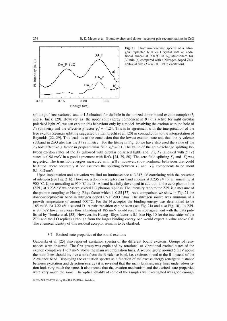
⊥ = 0.1. The value of the spin-exchange splitting be-tween exciton states of the Γ 5 (allowed with circular polarized light) and Γ 1, Γ 2 (allowed with E || c) states is 0.98 meV in a good agreement with Refs. [24, 29, 80]. The zero field splitting Γ1 and Γ2 was neglected. The transition energies measured with E || c, however, show nonlinear behaviour that could be fitted more accurately if one assumes the splitting between Γ 1 and Γ 2 components to be about 0.1–0.2 meV. Upon implantation and activation we find no luminescence at 3.315 eV correlating with the presence of nitrogen (see Fig. 21b). However, a donor–acceptor pair band appears at 3.235 eV for an annealing at 900 °C. Upon annealing at 950 °C the D–A band has fully developed in addition to the zero-phonon line (ZPL) at 3.235 eV we observe several LO phonon replicas. The intensity ratio to the ZPL is a measure of the phonon coupling or Huang–Rhys factor which is 0.85 [37]. As a comparison we show in Fig. 21 the donor-acceptor-pair band in nitrogen doped CVD ZnO films. The nitrogen source was ammonia at a growth temperature of around 600 °C. For the N-acceptor the binding energy was determined to be 165 meV. At 3.22 eV a second D–A pair transition can be seen (see Fig. 21a and also Fig. 10). Its ZPL is 20 meV lower in energy thus a binding of 185 meV would result in nice agreement with the data pub-lished by Thonke et al. [33]. However, its Huang–Rhys factor is 0.1 (see Fig. 10 for the intensities of the ZPL and the LO replica) although from the larger binding energy one would expect a value above 0.8. The chemical identity of this residual acceptor remains to be clarified.
3.7 Excited state properties of the bound excitons
Gutowski et al. [25] also reported excitation spectra of the different bound excitons. Groups of reso-nances were observed. The first group was explained by rotational or vibrational excited states of the exciton complexes 1 to 3 meV above the main recombination lines. A second group around 5 meV above the main lines should involve a hole from the B-valence band, i.e. excitons bound to the B- instead of the A-valence band. Displaying the excitation spectra as a function of the excess energy (energetic distance between excitation and detection energy) it is revealed that the main luminescence lines under observa-tion look very much the same. It also means that the creation mechanism and the excited state properties were very much the same. The optical quality of some of the samples we investigated was good enough
Fig. 21 Photoluminescence spectra of a nitro-gen implanted bulk ZnO crystal with an addi-tional anneal at 900 °C in N2 atmosphere for 30 min (a) compared with a Nitrogen doped ZnO epitaxial film (T = 4.2 K, HeCd excitation).

phys. stat. sol. (b) 241, No. 2 (2004) / www.pss-b.com 255
© 2004 WILEY-VCH Verlag GmbH & Co. KGaA, Weinheim
3.356 3.358 3.360 3.362 3.364
I6*
I4*
I6a
*I8*
I9
I8 I
6a
I6
I4
PL
Inte
nsi
ty(a
.u
.)
Energy (eV)
to observe excited state properties directly by low temperature photoluminescence, others could be seen in a narrow temperature range between 8 and 25 K. In the following we report on these findings: An E-P sample was annealed at 600 °C in oxygen atmosphere to partly remove I4 and reduce the carrier density since the exciton line became sharper after such a short treatment. Figure 22 shows a low temperature luminescence spectrum around the bound exciton line I4, I6/6a and I8. Approximately with a factor 30 less intense 4 small lines can be seen which have an energy separation (towards higher ener-gies) of 1.5, 1.2 and 1.1 meV with respect to the bound exciton lines (see Fig. 22 marked by stars). We interpret them as rotational/vibrational excited states. The energy levels are calculated using Eq. (11) [86]
2 2
22 2
2
(2 / )( , )
1 1 22 2
ma DE J
maJ D
ν
ν
⋅= −
+ + + +
�
�
, (11)
where ν and J are the vibrational and rotational quantum numbers respectively. D is the binding (local-ization) energy of the bound exciton, m is the relevant band mass and a the distance electron (hole)–impurity. We describe the donor bound excitons in analogy to the “pseudo-donor” model for acceptor bound excitons. In the “pseudo-donor model” the hole of the exciton is tightly bound to the neutral ac-ceptor and the electron is in a large orbit around the positively core. In such a case the band mass for electrons would enter into Eq. (2) as well as a distance of 1.8 nm (Bohr radius). We assume for the donor bound excitons that the electron is tightly bound and the hole will be in a large orbit. We used a band mass of 0.7 m0 which is calculated from the acceptor ionisation energy of 165 meV using the simple EMT-approach and a distance of 0.8 nm. The excited state levels are obtained from the difference be-tween ν = 0 and J = 0 and ν = 0 and J = 1. The results are for I4 1.08 meV (exp. 1.1 meV), for I6/6a 1.23 meV (exp. 1.2 meV) and for I8 1.36 meV (exp. 1.5 meV) without changing any parameter. Chang-ing the radius from 0.8 to 0.7 nm would reduce the energy for I4 from 1.08 to 0.9 meV whereas a change in the band mass by +0.1 (–0.1) gives an increase (decrease) to 1.2 (1.0) meV. For I9 and I10 we could not observe these transitions, they overlap either with I9 or I8. However, the excitation measurements of Gutowski et al. [25] can be used to test the model. They gave for I9 a value of 2.1 meV and for I10 it was 3.5 meV. We obtain for I9 1.84 meV and for I10 2.9 meV by inserting the respective binding energies into Eq. (11) without changing the other parameters. This nice agreement again points to a common origin of all bound exciton lines. At temperatures between 10 and 20 K we see that new lines emerge (see also [87]), they are thermally activated. The energetic distance to the respective bound exciton lines is (4.7 ± 0.2) meV which indicates an involvement of the B-valence band, the A–B valence band splitting has just this value (see Table 1).
Fig. 22 Photoluminescence spectra in the bound exciton region of a bulk ZnO crystal after annealing in N2 atmosphere at 600 °C for 30 min, the lines marked by a star belong to excited rotational states (T = 4.2 K, HeCd excitation).

256 B. K. Meyer et al.: Bound exciton and donor–acceptor pair recombinations in ZnO
© 2004 WILEY-VCH Verlag GmbH & Co. KGaA, Weinheim
0 50 100 150 200 250
PL
Inte
nsi
ty(a
.u)
1000/T (K-1)
3.356 3.360 3.364 3.368
I8B
I6B
I8A
,I6A
I6B
I8B
I6A
I8A b)a)
20 K
15 K
10 K
4 K
PL
Inte
nsi
ty(a
.u)
Energy (eV)
Fig. 23 a) Temperature dependent photoluminescence measurements showing the emergence of excited states involving the B-valence band labeled with the subscript B (bulk ZnO crystal after annealing in N2 atmosphere at 600 °C for 30 min); b) Arrhenius plot of the respective IA and IB and the corresponding fit to the data (for details see text).
Figure 23a shows for four different temperatures the photoluminescence spectra. We find these lines not only for I4, but also for all other lines from I6 to I9. They show a thermally activated behavior, first they increase in intensity and then drop as the main bound exciton lines do. In Fig. 23b we have collected the experimental data. The main bound exciton line stays constant from 4.2 to 20 K and then rapidly looses in intensity. D0XB gains in intensity up to 30 K and then shows an identical thermally activated decrease. The I6/6a and I8 intensities follow the dependence
1
1 expx
x
IE
AkT
= −
−
(12)
where Ex is the exciton localization energy (14 ± 2 meV for I6/6a and I8 in Fig. 23) and A is a constant. In the case of I6/6a (B) and I8 (B) the dependence can be fitted by
AB
1
1 exp expx
x
I BE E
A CkT kT
= − −
− +
(13)
where B and C are constants and EAB is the splitting between the A- and B-valence bands and Ex is the localization energy of the corresponding A bound exciton. The drawn lines in Fig. 23b are a fit to the data using Eqs. (12) and (13), respectivly. All bound exci-ton lines showed this behavior, for I10 it could not be resolved, it overlaps with the I9 recombination. Summarizing, the excited state properties of all bound exciton lines appear to be very similar. Rota-tional excited states as well as donor bound exciton states involving holes from the B-valence band could be observed. Further fine structure is not possible to resolve by steady state photoluminescence. How-ever, our results are in agreement with the PL excitation spectra of Gutowski et al. [25] despite the fact that we interpret the lines as donor bound excitons.
4 Discussion
In our investigations we sum up all arguments for an assignment of the bound exciton recombinations in ZnO.

phys. stat. sol. (b) 241, No. 2 (2004) / www.pss-b.com 257
© 2004 WILEY-VCH Verlag GmbH & Co. KGaA, Weinheim
(i) I2 and I3 are caused by ionized donor bound excitons. The magnetic field splitting and the zero field splitting obtained from the behavior in magnetic field and traced to zero field give no room for another interpretation. The angular dependence and the field dependence for E || c, B || c can only be fitted if the hole g-factor |gh
|| | < ge. The transitions observed are, therefore, due to a bound exciton where the hole has Γ7 symmetry. Thus, the lowest exciton state and the A-valence band also have Γ7 symmetry in agreement with Refs. [1, 15, 17–21, 25–28]. Note that a very strong argument for the Γ7–Γ9–Γ7 ordering comes from the two-photon absorption presented by Dinges et al. [89]. (ii) The bound exciton recombinations I4 to I10 are neutral donor bound excitons. This is demonstrated by the observation of two-electron-satellite transitions connected to each donor bound exciton. From the energetic distance of the TES lines to the bound exciton lines the donor binding energies were calculated. The linear relationship between the localization energy and the binding energy known as Haynes‘ rule supports this interpretation. (iii) For the first time we were able to identify the chemical nature of some donors participating in the near edge bound exciton recombinations. It immediately rules out that Gutowskis conclusions [25] – all excitons I5 to I10 are bound to acceptors – would be correct. I4 could be identified with hydrogen, I6/6a in agreement with Schillings [74] implantation studies with aluminum, I8 in agreement with Yaos data with gallium [75], and I9 with indium based on diffusion experiments. Their excited state properties appeared to be very similar in structure. Each principal bound exciton line is accompanied by high energy line, the energy separations vary from 1.1 to 3.4 meV (I4 to I10) depending on the magnitude of the localization energy. We interpret them as rotational excited states. For all bound exciton lines the same model de-scription has been used, a neutral donor which tightly binds the electron from the exciton and the remain-ing hole is in a larger orbit around the core of the complex. Using the band mass of 0.7 m0 and an orbit of 0.8 nm appropriate for a hole bound to shallow, effective-mass-like acceptor a very good agreement between experiment and theoretical description was achieved. The donor bound exciton states with the contribution of a hole from the B-valence band could be identified in temperature dependent studies. (iv) Doping experiments performed in the 70ies have been taken as an argument that Na and Li induce (shallow) acceptor states in ZnO [8]. Although never been stated the appearence of I9 with Na-doping and I10 with Li-doping and interpreted as neutral acceptor bound excitons implicated that Na and Li act as shallow acceptors in ZnO. From our experiments there is no evidence that Na and Li have shallow levels. In contrary, Li-and Na-related deep acceptor centers were observed in EPR and ODMR. The increase in resistivity in Li (Na)-doped samples can be explained by an interplay between shallow donors induced by unintentional doping and Li(Na)-related deep acceptors. (v) The 3.22 eV donor–acceptor-pair line is the only indication that acceptors are really incorporated into as-grown ZnO and could have a shallow level. We could not find a correlation of the intensity of the bound exciton lines to this D–A recombination giving any hints as to what impurity is incorporated. The very weak phonon coupling complicates the story furthermore. Comparing with ZnSe or ZnTe such a weak coupling would mean binding energies around 50 meV despite the fact that the acceptor has a bind-ing energy around 190 meV. (vi) Substitutional nitrogen on oxygen sites creates a shallow acceptor level in ZnO [see also 88] and participates in a shallow donor, shallow acceptor pair recombination. This was recently confirmed by time-resolved luminescence measurements [37]. The zero-phonon line is located at 3.235 eV and is fol-lowed by several longitudinal optical phonon replicas. From the position of the ZPL an acceptor binding energy of 165 meV is estimated. Still in the weak phonon coupling regime the Huang-Rhys factor is 0.8 very similar to that of ZnSe:N. We note that a D-A-P band with similar couplings has been observed in ZnO [90, 91] doped with As, for the binding energy of the As acceptor a value of (180 ± 10) was given [90]. Together with the appearance of the D-A-P transition also the spectrum in bound exciton spectral range changes. We could clearly see this in the implanted samples, where upon activation and annealing out the implantation damage two bound exciton lines grew in intensity. The line at 3.368 eV is an ion-ized donor bound exciton recombination. The behavior in magnetic field and the zero-field splitting are clear fingerprints of such a defect structure. The second bound exciton line appears more or less at the same position of I9 as in the Na-doped crystals. It is caused by an indium contamination upon annealing.

258 B. K. Meyer et al.: Bound exciton and donor–acceptor pair recombinations in ZnO
© 2004 WILEY-VCH Verlag GmbH & Co. KGaA, Weinheim
(vii) If ZnO will not behave substantially different from other II–VI compound semiconductors successful acceptor doping should manifest itself in the appearance of ionized donor and neutral acceptor bound exciton recombination together with shallow donor to shallow acceptor recombination. It is what we have observed for ZnO doped with nitrogen in epitaxially grown thin films and bulk crystals implanted with nitrogen. How-ever, as to the neutral nitrogen acceptor bound exciton we have no conclusive picture up to now. We note a conflict with recent theoretical work on the stability of acceptors in ZnO. Park et al. [92] find that the group-I elements will be stable upon distortion, whereas the group-V elements may act as AX-centers.
5 Summary
The binding energies of six donors giving rise to neutral donor bound exciton recombinations from 3.3628 to 3.353 eV have been determined from the observations of their two electron satellite transitions. Thermal annealing experiments in connection with Hall data and EPR/ENDOR give evidence that the I4 recombination is related to the hydrogen donor. We further present data on the binding energies of Al, Ga and In. Spectrally and spatially resolved cathodoluminescence measurements support that the 3.333 eV recombination is due to excitons bound to structural defects. Our current understanding on the behavior of nitrogen as a shallow acceptor is presented.
Acknowledgement This work was supported by BMBF (contract no. 01 BM 151).
References
[1] D. G. Thomas, J. Phys. Chem. Solids 15, 86 (1960). [2] H. D. Sun, T. Makino, N. T. Tuan, Y. Segawa, M. Kawasaki, A. Ohtomo, K. Tamura, and H. Koinuma, Appl.
Phys. Lett. 78, 2464 (2001). [3] A. Ohtomo, M. Kawasaki, T. Koida, K. Masubuchi, H. Koinuma, Y. Sakurai, Y. Yoshida, T. Yasuda, and Y.
Segawa, Appl. Phys. Lett. 72, 2466 (2001). [4] T. Makino, Y. Segawa, M. Kawasaki, A. Ohtomo, R. Shiroki, K. Tamura, T. Yasuda, and H. Koinuma, Appl.
Phys. Lett. 78, 1237 (2001). [5] T. Makino, C. H. Chia, N. T. Tuan, H. D. Sun, Y. Segawa, M. Kawasaki, A. Ohtomo, K. Tamura, and H. Koi-
numa, Appl. Phys. Lett. 77, 975 (2000). [6] D. C. Look, D. C. Reynolds, J. W. Hemsky, R. L. Jones, and J. R. Sizelove, Appl. Phys. Lett. 75 (1999). [7] G. Heiland, E. Mollwo, and F. Stöckmann, Solid State Phys. 8, 193 (1959). [8] E. Tomzig and H. Helbig, J. Lumin. 14, 403 (1976). [9] M. Joseph, H. Tabata, and T. Kawai, Jpn. J. Appl. Phys. 38, L1205 (1999). [10] D. C. Look, D. C. Reynolds, C. W. Litton, R. L. Jones, D. B. Eason, and G. Gantwell, Appl. Phys. Lett. 81,
1830 (2002). [11] Y. R. Ryu, S. Zhu, D. C. Look, J. M. Wrobel, H. M. Jeong, and H. W. White, J. Cryst. Growth 216, 330 (2000). [12] M. Joseph, H. Tabata, H. Saeki, K. Ueda, and T. Kawai, Physica B 302–303, 140 (2001). [13] Y. R. Ryu, W. J. Kim, and H. W. White, J. Cryst. Growth 219, 419 (2000). [14] K. Minegishi, Y. Koiwai, Y. Kikuchi, K. Yano, M. Kasuga, and A. Shimizu, Jpn. J. Appl. Phys. 36, L1453
(1997). [15] J. J. Hopfield, J. Phys. Chem. Solids 15, 97 (1960). [16] Y. S. Park. C. W. Litton, T. C. Collins, and D. C. Reynolds, Phys. Rev. 143, 512 (1966). [17] B. Segall, Phys. Rev. 163, 769 (1967). [18] W. Y. Liang and A. D. Yoffe, Phys. Rev. Lett. 20, 59 (1968). [19] K. Hümmer, phys. stat. sol. (b) 56, 249 (1973). [20] M. Rosenzweig, Diploma Thesis, TU Berlin, 1975. [21] G. Blattner, G. Kurtze, G. Schmieder, and C. Klingshirn, Phys. Rev. B 25, 7413 (1982). [22] B. C. Reynolds, D. C. Look, B. Jogai, C. W. Litton, G. Cantwell, and W. C. Harsch, Phys. Rev. B 60, 2340
(1999). [23] B. Gil, Phys. Rev. B 64, 201310 (R) (2001) see also Ref. 6 therein. [24] W. L. R. Lambrecht, A. V. Rodina, S. Limpijumnong, B. Segall, and B. K. Meyer, Phys. Rev. B 65, 075207
(2002).

phys. stat. sol. (b) 241, No. 2 (2004) / www.pss-b.com 259
© 2004 WILEY-VCH Verlag GmbH & Co. KGaA, Weinheim
[25] J. Gutowski, N. Presser, and I. Broser, Phys. Rev. B 38, 9746 (1988). [26] G. Blattner, C. Klingshirn, R. Helbig, and R. Meinl, phys. stat. sol. (b) 107, 105 (1981). [27] P. Loose, M. Rosenzweig, and M. Wöhlecke, phys. stat. sol. (b) 75, 137 (1976). [28] J. L. Birman, Phys. Rev. 114, 1490 (1959). [29] D. C. Reynolds, C. W. Litton, and T. C. Collins, Phys. Rev. 140, A1726 (1965). [30] D. C. Reynolds and T. C. Collins, Phys. Rev. 185, 1099 (1969). [31] H. J. Ko, Y. F. Chen. Z. Zhu, and T. Yao, Appl. Phys. Lett. 76, 1905 (2000). [32] H. Kato, M. Sano, M. Miyamoto, and T. Yao, J. Cryst. Growth 237–239, 538 (2002). [33] K. Thonke, Th. Gruber, N. Teofilov, R. Schönfelder, A. Waag, and R. Sauer, Physica B 308–310, 945 (2001). [34] A. Naumov, K. Wolf, T. Reisinger, H. Stanzl, and W. Gebhardt, J. Appl. Phys. 73, 2581 (1993). [35] S. Myhajlenko, J. L. Batstone, H. J. Hutchinson, and J. W. Steeds, J. Phys. C, Solid State Phys. 17, 6477
(1984). [36] D. C. Reynolds, D. C. Look, B. Jogai, C. W. Litton, T. C. Colins, W. Harsch, and G. Cantwell, Phys. Rev. B
57, 19, 57 (1998). [37] A. Zeuner, H. R. Alves, D. M. Hofmann, B. K. Meyer, A. Hoffmann, U. Haboeck, M. Straßburg, and
M. Dworzak, phys. stat. sol. (b) 234, R7 (2002). [38] D. C. Look, Mater. Sci. Eng. B 80, 383 (2001). [39] D. C. Look, R. L. Jones, J. R. Sizelove, N. Y. Garces, N. C. Giles, and L. E. Halliburton, phys. stat. sol. (a)
195, 171 (2003). [40] P. J. Dean, phys. stat. sol. (a) 81, 625 (1984). [41] S. Fujii, T. Terada, Y. Fujta, and T. Tuchi, Jpn. J. Appl. Phys. 28, L 1712 (1989). [42] S. Fischer, G. Steude, D. M. Hofmann, F. Kurth, F. Anders, M. Topf, B. K. Meyer, F. Bertram, M. Schmidt,
J. Christen, L. Eckey, J. Holst, A. Hoffmann, B. Mensching, and B. Rauschenbach, J. Cryst. Growth 189/190, 556 (1998).
[43] H. Alves, D. Pfisterer, A. Zeuner, T. Riemann, J. Christen, D. M. Hofmann, and B. K. Meyer, Opt. Mater. 23, 33 (2003).
[44] T. Riemann, J. Christen, G. Kaczmarczyk, A. Hoffmann, A. Zeuner, D. Hofmann, and B. K. Meyer, phys. stat. sol. (b) 229(2), 891 (2002).
[45] A. Zeuner, H. Alves, D. M. Hoffmann, B. K. Meyer, M. Heuken, J. Bläsing, and A. Krost, Appl. Phys. Lett. 80, 2078 (2002).
[46] J. Schneider and A. Räuber, Z. Naturforsch. 16a, 712 (1961). [47] P. H. Kasai, Phys. Rev. 130, 989 (1963). [48] C. Gonzales, D. Block, R. T. Cox, and A. Hervé, J. Cryst. Growth 59, 357 (1982). [49] D. Block, A. Hervé, and R. T. Cox, Phys. Rev. B 25, 6049 (1982). [50] N. Y. Garces, N. C. Giles, and L. E. Halliburton, G. Cantwell, D. B. Eason, D. C. Reynolds, and D. C. Look,
Appl. Phys. Lett. 80, 1334 (2002). [51] C. G. van de Walle, Phys. Rev. Lett. 85, 5, 1012 (2000). [52] D. M. Hofmann, A. Hofstaetter, F. Leiter, H. Zhou, F. Henecker, and B. K. Meyer, Phys. Rev. Lett. 88(4), 045504
(2002). [53] A. Pöppl and G. Völkel, phys. stat. sol. (a) 115, 247 (1989). [54] G. K. Born, A. B. Hofstaetter, A. O. Scharmann, G. M. Arnett, R. L. Kroes, and U. E. Wegner, phys. stat. sol.
(a) 4, 675 (1971). [55] K. Vanheusden, C. H. Seager, W. L. Warren, D. R. Tallant, and J. A. Voigt, Appl. Phys. Lett. 68, 403 (1996). [56] J. M. Smith and W. E. Vehse, Phys. Lett. 31A, 147 (1970). [57] V. Soriano and D. Galland, phys. stat. sol. (b) 77, 739 (1976). [58] C. Gonzales, D. Galland, and A. Herve, phys. stat. sol. (b) 72, 309 (1975). [59] K. Leutwein and J. Schneider, Z. Naturforsch. 26a, 1236 (1971). [60] A. L. Taylor, G. Filipovich, and G. K. Lindeberg, Solid State Commun. 8, 1359 (1970). [61] D. Galland and A. Herve, Solid State Commun. 14, 953 (1974). [62] B. Schallenberger und A. Hausmann, Z. Phys. B 23, 177 (1976). [63] B. Schallenberger und A. Hausmann, Z. Phys. B 44, 143 (1981). [64] J. Schneider and O. Schirmer, Z. Naturforsch. 18a, 20 (1963). [65] O. F. Schirmer, J. Phys. Chem. Solids 29, 1407 (1968). [66] D. Zwingel and F. Gärtner, Solid State Commun. 14, 45 (1974). [67] R. T. Cox, D. Block, A. Hervé, R. Picard, and C. Santier, Solid State Commun. 77, 25 (1978).

260 B. K. Meyer et al.: Bound exciton and donor–acceptor pair recombinations in ZnO
© 2004 WILEY-VCH Verlag GmbH & Co. KGaA, Weinheim
[68] F. H. Leiter, Thesis, Gießen, 2002. [69] W. E. Carlos, E. R. Glaser, and D. C. Look, Physica B 308–310, 976 (2001). [70] N. Y. Garces, Lijun Wang, N. C. Giles, L. E. Halliburton, G. Cantwell, and D. B. Eason, J. Appl. Phys. 94(1),
519 (2003). [71] F. H. Leiter, H. R. Alves, A. Hofstaetter, D. M. Hofmann, and B. K. Meyer, phys. stat. sol. (b) 226(1),
R4 (2001). [72] E. V. Lavrov, J. Weber, F. Börrnert, C. G. van de Walle, and R. Helbig, Phys. Rev. B 66, 165205 (2002). [73] M. D. McCluskey, S. J. Jokela, K. K. Zhuravlev, P. J. Simpson, and K. G. Lynn, Appl. Phys. Lett. 81, 20, 3807
(2002). [74] M. Schilling, R. Helbig, and G. Pensl, J. Lumin. 33, 201 (1985). [75] H. J. Ko, Y. F. Chen. S. K. Hong, H. Wenisch, and T. Yao, Appl. Phys. Lett. 77(23), 3761 (2000). [76] D. G. Thomas, J. Phys. Chem. Solids 9, 31 (1958). [77] M. Engineer and N. Tzoar, Phys. Rev. B 8, 702 (1973). [78] B. Hönerlage and U. Schröder, Phys. Rev. B 16, 3608 (1977). [79] C. H. Henry and K. Nassau, Phys. Rev. B 2, 997 (1970). [80] R. Wheeler and J. O. Dimmock, Phys. Rev. 125, 1805 (1962). [81] A. V. Rodina, M. Dietrich, A. Goeldner, L. Eckey, A. Hoffmann, Al. L. Efros, M. Rosen, and B. K. Meyer,
Phys. Rev. B 64, 115204 (2001). [82] J. Sak, Phys. Rev. B 3, 3356 (1971). [83] D. M. Larsen, Phys. Rev. B 9, 823 (1974). [84] J. R. Haynes, Phys. Rev. Lett. 4, 361 (1960). [85] A.V. Rodina, M. Strassburg, M. Dworzak, U. Haboeck, A. Hoffmann, A. Zeuner, H. R. Alves, D. M. Hof-
mann, and B. K. Meyer, to be published. [86] W. Rühle and W. Klingenstein, Phys. Rev. B 18(12), 7011 (1978). [87] C. Boemare, T. Monteiro, M. J. Soares, J. G. Guilherme, and E. Alves, Physica B 308–310, 85 (2001). [88] J. F. Rommeluére, L. Svob, F. Jomard, J. Mimila-Arroyo, A. Lusson. V. Sallet, and Y. Marfaing, Appl. Phys.
Lett. 83(2), 287 (2003). [89] R. Dinges, D. Fröhlich, B. Staginnus, and W. Staude, Phys. Rev. Lett. 25, 922 (1970). [90] C. Morhain, M. Teisseire, S. Vézian, F. Vigué, F. Raymond, P. Lorenzini, J. Guion, G. Neu, and J.-P. Faurie,
phys. stat. sol. (b) 229(2), 881 (2002). [91] Y. R. Ryu, T. S. Lee, and H. W. White, Appl. Phys. Lett. 83(1), 87 (2003). [92] C. H. Park, S. B. Zhang, and Su-Huai Wei, Phys. Rev. B 66, 073202 (2002). [93] Landoldt-Börnstein, Numerical data and functional relationships in science and technology, Vol. III/17b and
Vol. III, 41. Bruno K. Meyer has been a professor at the I. Physics Institute within the Justus Liebig University of Giessen in Germany since 1996. His scientific interests include synthesis of semiconductor oxides by chemical vapor deposition and magnetron sputtering especially with respect to doping issues, materials science of electro- and thermochromic material, recombination phenomena and defect characterization by magnetic resonance. Meyer earned his PhD in physics in 1983 as well as his habilitation 1987 from Paderborn University. From 1990 to 1996 he was professor at the Technical University Munich.