Bosch Group 24i RSF - A.C.Wilgar Bosch/24i RSF GCN… · bosch group 24i rsf wall mounted...
36
Bosch Group 24i RSF WALL MOUNTED COMBINATION BOILER FOR CENTRAL HEATING AND MAINS FED DOMESTIC HOT WATER INSTALLATION AND SERVICING INSTRUCTIONS GC NUMBERS N.G. 47 311 37 L.P.G. 47 311 38 BOILER OUTPUT To Domestic Hot Water – Modulated Control Minimum 7.5 kW (25,600 Btu/h) Maximum 23.4 kW (80,000 Btu/h) To Central Heating – Modulated Control\ Auto Range Rated Minimum 7.5 kW (25,600 Btu/h) Maximum 23.4 kW (80,000 Btu/h) THESE INSTRUCTIONS APPLY IN THE UK ONLY THESE INSTRUCTIONS ARE TO BE LEFT WITH THE USER OR AT THE GAS METER This appliance must be installed by a competent person in accordance with the Gas Safety (Installation and Use) Regulations 1994
Transcript of Bosch Group 24i RSF - A.C.Wilgar Bosch/24i RSF GCN… · bosch group 24i rsf wall mounted...
Bosch Group
24i RSFWALL MOUNTED COMBINATION BOILER FOR CENTRAL HEATING
AND MAINS FED DOMESTIC HOT WATER
INSTALLATION ANDSERVICING INSTRUCTIONS
GC NUMBERSN.G. 47 311 37 L.P.G. 47 311 38
BOILER OUTPUTTo Domestic Hot Water – Modulated Control
Minimum 7.5 kW (25,600 Btu/h)Maximum 23.4 kW (80,000 Btu/h)
To Central Heating – Modulated Control\Auto Range Rated
Minimum 7.5 kW (25,600 Btu/h)Maximum 23.4 kW (80,000 Btu/h)
THESE INSTRUCTIONS APPLY IN THE UK ONLYTHESE INSTRUCTIONS ARE TO BE LEFT WITH THE USER OR AT THE GAS METER
This appliance must be installed by a competent person in accordancewith the Gas Safety (Installation and Use) Regulations 1994
1.1 Gas Safety (Installation and Use) Regulations, October 1994all gas appliances must be installed by a competent person inaccordance with the above regulations. Failure to installappliances correctly could lead to prosecution.1.2 The manufacturers notes must not be taken, in any way, asoverriding statutory obligations.1.3 The compliance with a British Standard does not, of itself,confer immunity from legal obligations. In particular theinstallation of this appliance must be in accordance with therelevant requirements of the following;Gas Safety (Installation and Use) Regulations 1994 as amended.Current IEE Wiring Regulations BS 7671.Local Building Regulations.Building Standards (Scotland)(Consolidation).Bylaws of the local Water Company. Health and Safety Document No. 635 (Electricity at WorkRegulations).The British Gas Material and Installation Specification for centralheating and hot waterIt should be in accordance with the relevant recommendations ofthe following British Standards.BS6798:1987 Specification for installation of gas fired hot waterboilers of rated input not exceeding 60 kW.BS5449:1990 Central Heating for Domestic Premises.BS5546:1990 Installation of gas hot water supplies for domesticpurposes.BS5440:1:1990 Flues and Ventilation for gas appliances of ratedinput not exceeding 60 kW: Flues.BS5440:2:1989 Flues and Ventilation for gas appliances of ratedinput not exceeding 60kW: Air Supply.BS6891:1988 Installation of low pressure gas pipeworkinstallations up to 28mm (R1).BS7593:1993 Central Heating system cleansing and flushing.BS5482:PART 1 Domestic Butane and Propane gas burninginstallations in permanent dwellings.1.4 To ensure that the installation will perform to the higheststandards, the system and components should conform to anyother relevant British Standards in addition to those mentionedin the instructions.1.5 The appliance complies with the Essential Requirements ofthe Gas Appliance Directive and other Directives currentlyapplicable.1.6 This appliance contains no asbestos products.There is no potential hazard due to the appliance beingelectrically unsafe.There are no substances used that are a potential hazard inrelation to the COSHH Regulations 1988.1.7 The advice and instructions given in this document covers, asfar as possible, the foreseeable situations which may arise. ContactWorcester Heat Systems Technical Helpline for advice on specificinstallations.
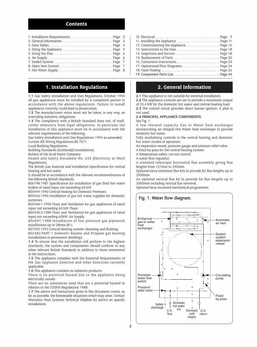
2.1 This appliance is not suitable for external installation.2.2 The appliance controls are set to provide a maximum outputof 23.4 kW for the domestic hot water and central heating load.2.3 The control circuit provides direct burner ignition. A pilot isnot used.2.4 PRINCIPAL APPLIANCE COMPONENTS.See Fig. 1.A low thermal capacity Gas to Water heat exchangerincorporating an integral Hot Water heat exchanger to providedomestic hot water.Fully modulating controls in the central heating and domestichot water modes of operation.An expansion vessel, pressure gauge and pressure relief valve.A fixed by-pass for the central heating system.A Temperature safety cut-out control.A water flow regulator.A standard telescopic horizontal flue assembly giving fluelengths from 127mm to 350mm.Optional extra extension flue kits to provide for flue lengths up to2500mm.An optional vertical flue kit to provide for flue lengths up to3000mm including vertical flue terminal.Optional facia mounted mechanical programmer.
2. General Information1. Installation Regulations
2
1. Installation Requirements . . . . . . . . . . . . . . . . . . . . . . . . . Page 2 10. Electrical . . . . . . . . . . . . . . . . . . . . . . . . . . . . . . . . . . . . . . . Page 92. General Information . . . . . . . . . . . . . . . . . . . . . . . . . . . . . . Page 2 11. Installing the Appliance . . . . . . . . . . . . . . . . . . . . . . . . . . Page 113. Data Tables . . . . . . . . . . . . . . . . . . . . . . . . . . . . . . . . . . . . . . Page 4 12. Commissioning the Appliance . . . . . . . . . . . . . . . . . . . . Page 164. Siting the Appliance . . . . . . . . . . . . . . . . . . . . . . . . . . . . . . Page 5 13. Instructions to the User . . . . . . . . . . . . . . . . . . . . . . . . . . Page 185. Siting the Flue. . . . . . . . . . . . . . . . . . . . . . . . . . . . . . . . . . . . Page 6 14. Inspection and Service. . . . . . . . . . . . . . . . . . . . . . . . . . . Page 186. Air Supply . . . . . . . . . . . . . . . . . . . . . . . . . . . . . . . . . . . . . . . Page 6 15. Replacement of Parts . . . . . . . . . . . . . . . . . . . . . . . . . . . . Page 207. Sealed System . . . . . . . . . . . . . . . . . . . . . . . . . . . . . . . . . . . Page 7 16. Conversion Instructions . . . . . . . . . . . . . . . . . . . . . . . . . . Page 238. Open Vent System . . . . . . . . . . . . . . . . . . . . . . . . . . . . . . . . Page 7 17. Operational Flow Diagrams. . . . . . . . . . . . . . . . . . . . . . . Page 249. Hot Water Supply . . . . . . . . . . . . . . . . . . . . . . . . . . . . . . . . Page 8 18. Fault Finding . . . . . . . . . . . . . . . . . . . . . . . . . . . . . . . . . . . Page 26. . . . . . . . . . . . . . . . . . . . . . . . . . . . . . . . . . . . . . . . . . . . . . . . . . . . . . . . . 19. Component Parts List. . . . . . . . . . . . . . . . . . . . . . . . . . . . Page 34
Contents
Fig. 1. Water flow diagram.
Bi-thermalgas to waterheatexchanger
Automaticair vent
Domesticwater flowswitch
Pressurerelief valve
Safetydischarge
Domestichot water
out Domesticcold
supply
C.H.return
Sealedsystemexpansionvessel
Circulatingpump
Fixedby-pass
C.H.flow
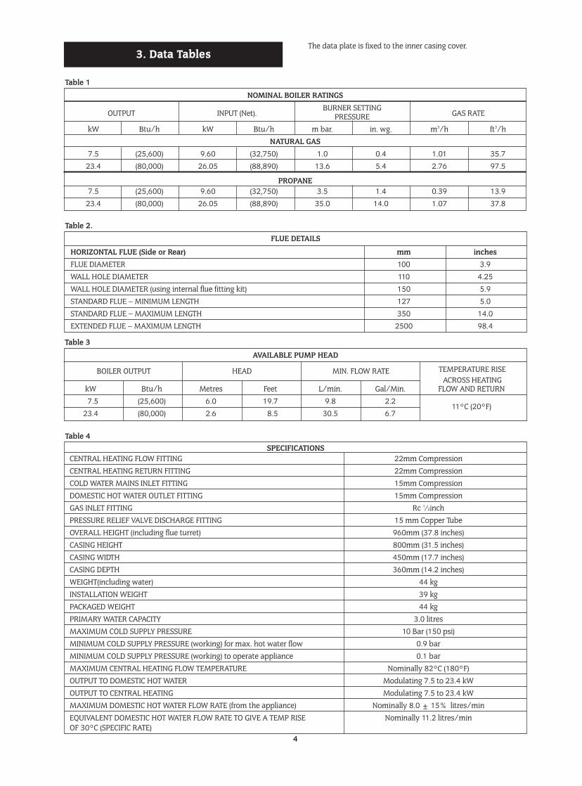
2.5 ELECTRICAL SUPPLYMains supply: 230V ~, 50 Hz, 180 watts.External fuse: 3A., Internal fuses: 2AT HRC(F1), and 1 AF (F2).2.6 GAS SUPPLYThe boiler requires 2.76 m3/h (97.5 ft3/hr) of natural gas with acalorific value of 37.78 MJ/m3 (1014 Btu/ft3) or 1.07 m3/h (37.8ft3/hr) of propane with a calorific value of 95.65 MJ/m3 (2568Btu/ft3). The meter governor should deliver a dynamic pressureof 20 mbar (8in w.g.) at the appliance, equivalent to a pressure ofabout 19-19.5 mbar at the gas valve on natural gas or 37.0 mbar(14.8in w.g.) at the appliance for propane.The gas meter and supply pipes must be capable of supplyingthis quantity of gas in addition to the demand from any otherappliances being served. The table below gives an indication oflimiting gas pipe lengths and the allowance to be made forfittings. Refer to BS6891 for further information.The complete installation, including the gas meter, must betested for soundness and purged. Refer to BS 6891.
Note: Each fitting used in the gas line from the meter isequivalent to a length of straight pipe which must be added tothe straight pipe length to give the total length.i.e.: Bend = 0.5 metres, Tee = 0.5 metres, 90° Bend = 0.3metres.2.7 PACKINGThe appliance and flue components are packaged separately.2.8 GENERAL INSTALLATIONThe appliance is for connection to a sealed system only.The specif ied ventilation openings made into a wall orcompartment door must not be obstructed.If the appliance is to be fitted into a compartment then thecompartment must conform to the requirements of BS 6798:1987: Section 7.Do not place anything on top of the appliance.The clearances specified for servicing must be maintained.2.9 FLUEThe appliance has a multi-directional fanned flue system.The standard telescopic flue assembly length is from 127mm to350mm.Extension flue lengths available are from 350mm to 2500mm.An optional vertical flue kit to provide for flue lengths up to3000mm including vertical flue terminal.A terminal guard, Type K2, GC 393 553, is available from TowerFlue Components, Vale Rise, Tonbridge, TN9 1TB.Do not allow the flue terminal fitted to the outside wall tobecome obstructed or damaged.A kit for internal fixing of the flue is available separately.2.10 CONTROLSThe electronic control system and gas valve modulate the heatinput in response to the domestic hot water temperature andcentral heating setting between minimum and maximum.The Central Heating Temperature control knob provides for theselection of domestic hot water only (Turned fully anti-clockwise)or central heating and domestic hot water (Turned clockwise).A facia mounted programmer is available as an optional extra. Aremote mounted programmer may be connected to theappliance.There is provision for the connection of a mains voltage roomthermostat and/or a frost thermostat.The electronic controls prevent rapid cycling of the appliance inthe central heating mode.
2.11 SYSTEM NOTESIMPORTANTCheck that no dirt is left in either the gas or water pipework asthis could cause damage to the appliance. The heating systemshould be f lushed and treated in accordance with therecommendations of BS 7593:1992. Thoroughly flush cold watermains supply and purge the gas supply before finally connectingthe appliance.The water pipe connections throughout a sealed system must becapable of sustaining a pressure of up to 3 bar.Radiator valves must conform to the requirements of BS2767:1991.The relief valve discharge must be directed away from anyelectrical components or where it would cause a hazard to theuser.A drain cock to BS 2879 must be fitted to the lowest point of thesystem.For circuit design purposes it is important that due note is takenof the information given in Table 3, section 3 relating to theavailable pump head.2.12 SHOWERS, BIDETS, TAPS AND MIXING VALVESHot and cold taps and mixing valves used in the system must besuitable for operating at mains pressure.Thermostatically controlled shower valves will guard against theflow of water at too high a temperature.Hot and cold mains fed water can be supplied direct to an over-rim flushing bidet subject to local Water Company requirements.With all mains fed systems the flow of water from the individualtaps wil l vary with the number of outlets operatedsimultaneously and the cold water mains supply pressure to theproperty. Flow balancing using “Ball-o-Fix” type valves isrecommended to avoid an excessive reduction in flow toindividual outlets.2.13 SAFETY CONSIDERATIONSThe appliance must not be operated in a waterless condition.The appliance must not be operated with the boiler inner casingcover removed.Work must not be carried out on the appliance without the gasand electricity supplies being switched off.Checks must be made to ensure that the ventilation openingsmade into walls and partitions are unobstructed and the correctsize.2.14 OPERATIONDomestic Hot Water: With a demand for hot water the burnerwill light at its maximum setting and then automatically adjustits output to maintain the temperature of the delivered water.When hot water is no longer required, the burner will extinguish.The fan and pump may continue to run for a short period todissipate the residual heat from the appliance.Central Heating: With a demand for heating the burner will lightat its minimum setting and gradually increase to give acontrolled temperature rise. When the required heatingtemperature is achieved the output of the appliance is thenautomatically adjusted to maintain the temperature of thesystem. The output can reduce down to a minimum of 7.5 kW. Ifthe system no longer requires even the minimum output tomaintain the desired room temperature the burner willextinguish. The fan and pump may continue to run to dissipatethe residual heat from the appliance. The appliance will remainoff for a fixed period before re-lighting to automatically meet thesystem requirements.Domestic Hot Water and Central Heating: The appliance willsupply heat to the central heating system as required. A demandfor domestic hot water at a tap or shower will override thecentral heating requirement for the period of the domestic hotwater demand. When hot water is no longer required theappliance will return to the central heating state and its normalmode of operation. The fan may continue to run to dissipate theresidual heat from the appliance as necessary.2.15 DOMESTIC SUPPLYDevices capable of preventing the flow of expansion water mustnot be fitted unless separate arrangements have been made.
3
Total length of gas supply pipe Pipe size(metres) (Ømm)
3 6 9 12Propane
Gas Discharge
1.5 – – – 15
Rate
8.0 5.2 4.2 3.6 22
(m3/hr)
15.9 8.8 8.5 7.2 28Natural Gas
8.7 5.8 4.6 – 2218.0 12.0 9.4 – 28
GasDischarge
Rate
(m3/hr)
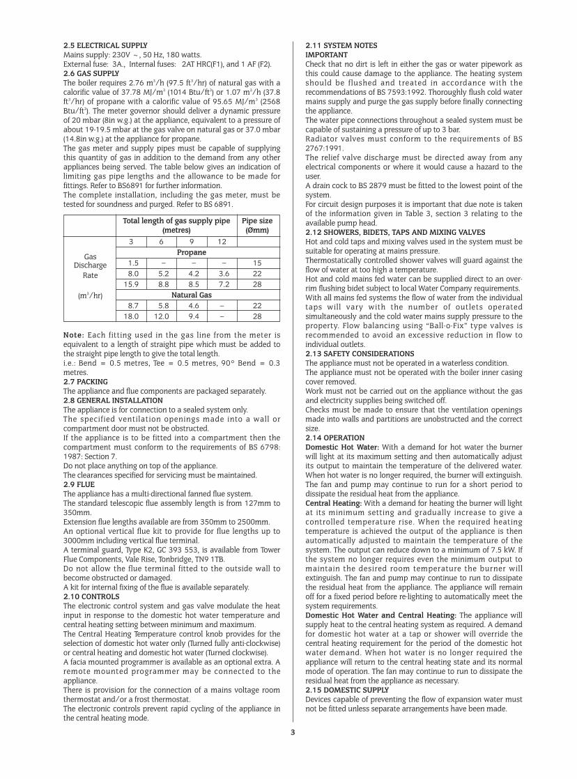
The data plate is fixed to the inner casing cover.3. Data Tables
4
NOMINAL BOILER RATINGS
OUTPUT INPUT (Net).BURNER SETTING
GAS RATEPRESSUREkW Btu/h kW Btu/h m bar. in. wg. m3/h ft3/h
NATURAL GAS7.5 (25,600) 9.60 (32,750) 1.0 0.4 1.01 35.7
23.4 (80,000) 26.05 (88,890) 13.6 5.4 2.76 97.5
PROPANE7.5 (25,600) 9.60 (32,750) 3.5 1.4 0.39 13.9
23.4 (80,000) 26.05 (88,890) 35.0 14.0 1.07 37.8
Table 1
AVAILABLE PUMP HEAD
BOILER OUTPUT HEAD MIN. FLOW RATE TEMPERATURE RISEACROSS HEATING
kW Btu/h Metres Feet L/min. Gal/Min. FLOW AND RETURN7.5 (25,600) 6.0 19.7 9.8 2.2
11°C (20°F)23.4 (80,000) 2.6 8.5 30.5 6.7
Table 3
SPECIFICATIONSCENTRAL HEATING FLOW FITTING 22mm CompressionCENTRAL HEATING RETURN FITTING 22mm CompressionCOLD WATER MAINS INLET FITTING 15mm CompressionDOMESTIC HOT WATER OUTLET FITTING 15mm CompressionGAS INLET FITTING Rc 1⁄2inchPRESSURE RELIEF VALVE DISCHARGE FITTING 15 mm Copper TubeOVERALL HEIGHT (including flue turret) 960mm (37.8 inches)CASING HEIGHT 800mm (31.5 inches)CASING WIDTH 450mm (17.7 inches)CASING DEPTH 360mm (14.2 inches)WEIGHT(including water) 44 kgINSTALLATION WEIGHT 39 kgPACKAGED WEIGHT 44 kgPRIMARY WATER CAPACITY 3.0 litresMAXIMUM COLD SUPPLY PRESSURE 10 Bar (150 psi)MINIMUM COLD SUPPLY PRESSURE (working) for max. hot water flow 0.9 barMINIMUM COLD SUPPLY PRESSURE (working) to operate appliance 0.1 barMAXIMUM CENTRAL HEATING FLOW TEMPERATURE Nominally 82°C (180°F)OUTPUT TO DOMESTIC HOT WATER Modulating 7.5 to 23.4 kWOUTPUT TO CENTRAL HEATING Modulating 7.5 to 23.4 kWMAXIMUM DOMESTIC HOT WATER FLOW RATE (from the appliance) Nominally 8.0 ± 15% litres/minEQUIVALENT DOMESTIC HOT WATER FLOW RATE TO GIVE A TEMP RISE Nominally 11.2 litres/minOF 30°C (SPECIFIC RATE)
Table 4
FLUE DETAILS
HORIZONTAL FLUE (Side or Rear) mm inchesFLUE DIAMETER 100 3.9WALL HOLE DIAMETER 110 4.25WALL HOLE DIAMETER (using internal flue fitting kit) 150 5.9STANDARD FLUE – MINIMUM LENGTH 127 5.0STANDARD FLUE – MAXIMUM LENGTH 350 14.0EXTENDED FLUE – MAXIMUM LENGTH 2500 98.4
Table 2.
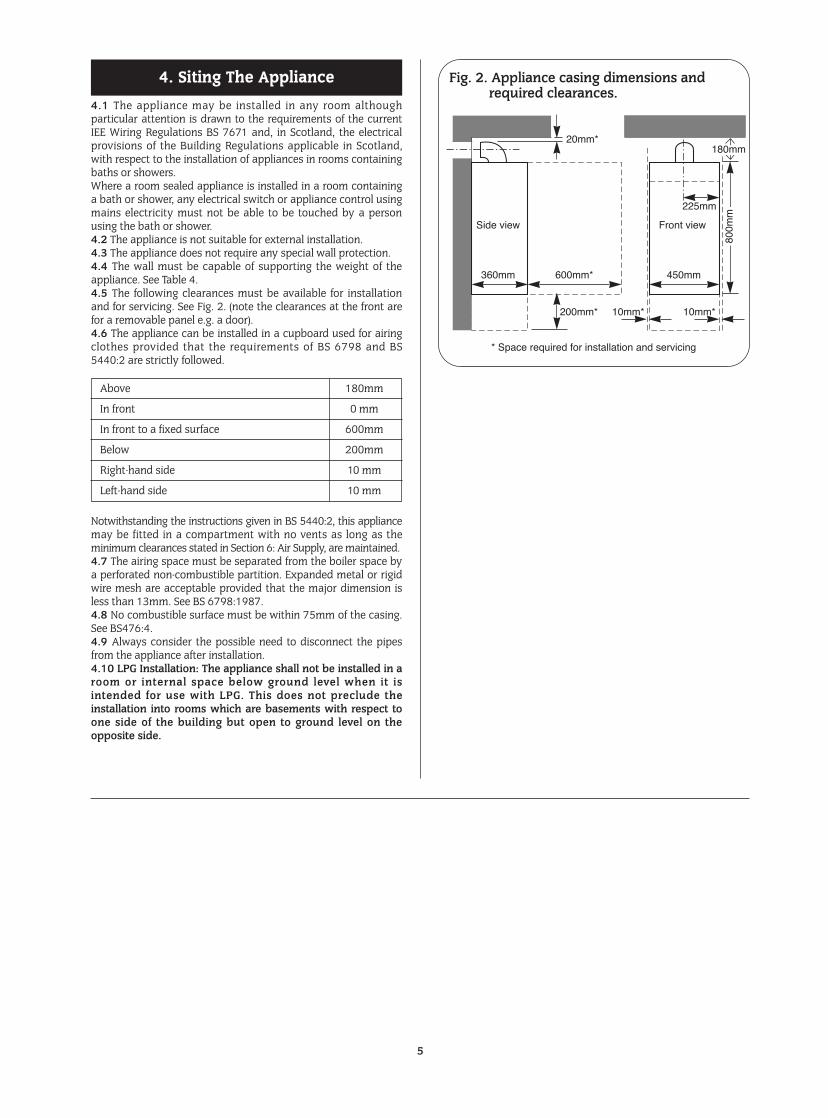
4.1 The appliance may be installed in any room althoughparticular attention is drawn to the requirements of the currentIEE Wiring Regulations BS 7671 and, in Scotland, the electricalprovisions of the Building Regulations applicable in Scotland,with respect to the installation of appliances in rooms containingbaths or showers.Where a room sealed appliance is installed in a room containinga bath or shower, any electrical switch or appliance control usingmains electricity must not be able to be touched by a personusing the bath or shower.4.2 The appliance is not suitable for external installation.4.3 The appliance does not require any special wall protection.4.4 The wall must be capable of supporting the weight of theappliance. See Table 4.4.5 The following clearances must be available for installationand for servicing. See Fig. 2. (note the clearances at the front arefor a removable panel e.g. a door).4.6 The appliance can be installed in a cupboard used for airingclothes provided that the requirements of BS 6798 and BS5440:2 are strictly followed.
Notwithstanding the instructions given in BS 5440:2, this appliancemay be fitted in a compartment with no vents as long as theminimum clearances stated in Section 6: Air Supply, are maintained.4.7 The airing space must be separated from the boiler space bya perforated non-combustible partition. Expanded metal or rigidwire mesh are acceptable provided that the major dimension isless than 13mm. See BS 6798:1987.4.8 No combustible surface must be within 75mm of the casing.See BS476:4.4.9 Always consider the possible need to disconnect the pipesfrom the appliance after installation.4.10 LPG Installation: The appliance shall not be installed in aroom or internal space below ground level when it isintended for use with LPG. This does not preclude theinstallation into rooms which are basements with respect toone side of the building but open to ground level on theopposite side.
4. Siting The Appliance
5
Above 180mm
In front 0 mm
In front to a fixed surface 600mm
Below 200mm
Right-hand side 10 mm
Left-hand side 10 mm
Fig. 2. Appliance casing dimensions andrequired clearances.
Side view
360mm 600mm*
20mm*
200mm* 10mm*
* Space required for installation and servicing
Front view
450mm
10mm*
225mm
180mm
800m
m
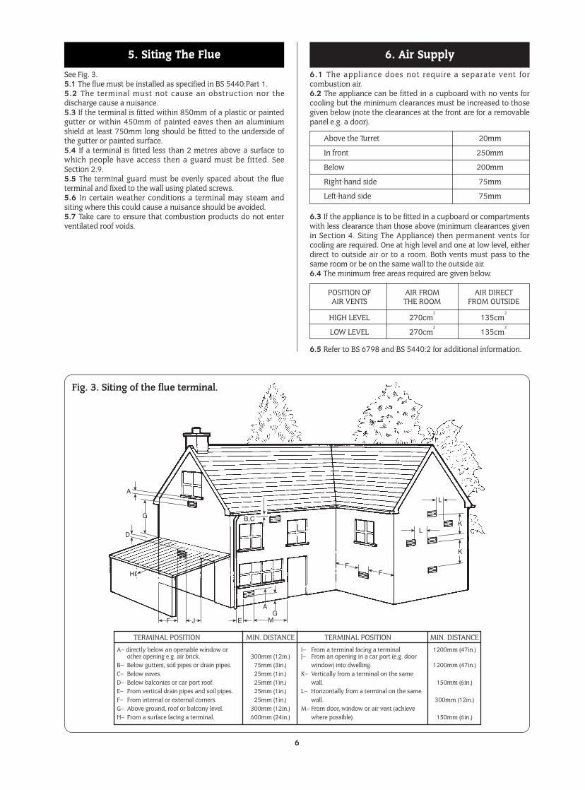
See Fig. 3.5.1 The flue must be installed as specified in BS 5440:Part 1.5.2 The terminal must not cause an obstruction nor thedischarge cause a nuisance.5.3 If the terminal is fitted within 850mm of a plastic or paintedgutter or within 450mm of painted eaves then an aluminiumshield at least 750mm long should be fitted to the underside ofthe gutter or painted surface.5.4 If a terminal is fitted less than 2 metres above a surface towhich people have access then a guard must be fitted. SeeSection 2.9.5.5 The terminal guard must be evenly spaced about the flueterminal and fixed to the wall using plated screws.5.6 In certain weather conditions a terminal may steam andsiting where this could cause a nuisance should be avoided.5.7 Take care to ensure that combustion products do not enterventilated roof voids.
6.1 The appliance does not require a separate vent forcombustion air.6.2 The appliance can be fitted in a cupboard with no vents forcooling but the minimum clearances must be increased to thosegiven below (note the clearances at the front are for a removablepanel e.g. a door).
6.3 If the appliance is to be fitted in a cupboard or compartmentswith less clearance than those above (minimum clearances givenin Section 4. Siting The Appliance) then permanent vents forcooling are required. One at high level and one at low level, eitherdirect to outside air or to a room. Both vents must pass to thesame room or be on the same wall to the outside air.6.4 The minimum free areas required are given below.
6.5 Refer to BS 6798 and BS 5440:2 for additional information.
6. Air Supply5. Siting The Flue
6
L
LK
K
FF
GA
MEJF
HI
D
G
A
B,C
Fig. 3. Siting of the flue terminal.
TERMINAL POSITION MIN. DISTANCE TERMINAL POSITION MIN. DISTANCEA– directly below an openable window or I– From a terminal facing a terminal 1200mm (47in.)
other opening e.g. air brick. 300mm (12in.) J– From an opening in a car port (e.g. doorB– Below gutters, soil pipes or drain pipes. 75mm (3in.) window) into dwelling. 1200mm (47in.)C– Below eaves. 25mm (1in.) K– Vertically from a terminal on the sameD– Below balconies or car port roof. 25mm (1in.) wall. 150mm (6in.)E– From vertical drain pipes and soil pipes. 25mm (1in.) L– Horizontally from a terminal on the sameF– From internal or external corners. 25mm (1in.) wall. 300mm (12in.)G– Above ground, roof or balcony level. 300mm (12in.) M– From door, window or air vent (achieveH– From a surface facing a terminal. 600mm (24in.) where possible). 150mm (6in.)
Above the Turret 20mm
In front 250mm
Below 200mm
Right-hand side 75mm
Left-hand side 75mm
POSITION OF AIR FROM AIR DIRECTAIR VENTS THE ROOM FROM OUTSIDE
HIGH LEVEL 270cm2
135cm2
LOW LEVEL 270cm2
135cm2
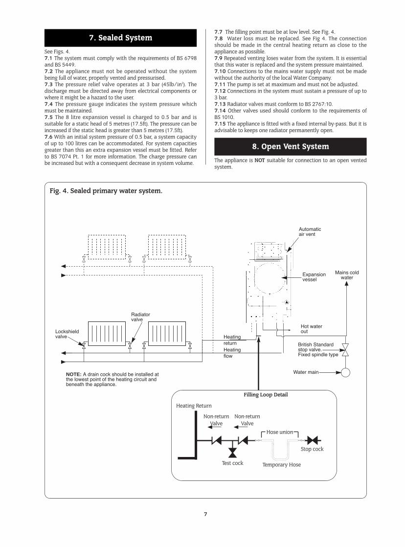
See Figs. 4.7.1 The system must comply with the requirements of BS 6798and BS 5449.7.2 The appliance must not be operated without the systembeing full of water, properly vented and pressurised.7.3 The pressure relief valve operates at 3 bar (45lb/in2). Thedischarge must be directed away from electrical components orwhere it might be a hazard to the user.7.4 The pressure gauge indicates the system pressure whichmust be maintained.7.5 The 8 litre expansion vessel is charged to 0.5 bar and issuitable for a static head of 5 metres (17.5ft). The pressure can beincreased if the static head is greater than 5 metres (17.5ft).7.6 With an initial system pressure of 0.5 bar, a system capacityof up to 100 litres can be accommodated. For system capacitiesgreater than this an extra expansion vessel must be fitted. Referto BS 7074 Pt. 1 for more information. The charge pressure canbe increased but with a consequent decrease in system volume.
7.7 The filling point must be at low level. See Fig. 4.7.8 Water loss must be replaced. See Fig 4. The connectionshould be made in the central heating return as close to theappliance as possible.7.9 Repeated venting loses water from the system. It is essentialthat this water is replaced and the system pressure maintained.7.10 Connections to the mains water supply must not be madewithout the authority of the local Water Company.7.11 The pump is set at maximum and must not be adjusted.7.12 Connections in the system must sustain a pressure of up to3 bar.7.13 Radiator valves must conform to BS 2767:10.7.14 Other valves used should conform to the requirements ofBS 1010.7.15 The appliance is fitted with a fixed internal by-pass. But it isadvisable to keeps one radiator permanently open.
The appliance is NOT suitable for connection to an open ventedsystem.
8. Open Vent System
7. Sealed System
7
Fig. 4. Sealed primary water system.
Automaticair vent
Expansionvessel
Hot waterout
Water main
HeatingreturnHeatingflow
Radiatorvalve
Lockshieldvalve
Mains coldwater
British Standardstop valve.Fixed spindle type
NOTE: A drain cock should be installed atthe lowest point of the heating circuit andbeneath the appliance.
Filling Loop Detail
Heating Return
Non-return Valve
Non-return Valve
Test cock
Hose union
Stop cock
Temporary Hose
9.1 The following are general requirements and, if necessary,reference should be made to the local Water Company beforefitting the appliance.9.2 MAINS COLD WATER INLET. Devices capable of preventingthe flow of expansion water must not be fitted unlessseparate arrangements have been made. A mini expansion vessel kit is available which contains thenecessary parts for fitting an internal expansion vessel to theappliance.See Section 19 COMPONENT PARTS LIST.A thread sealant compatible with potable water must beused. An external expansion vessel may be fitted on themains cold water connection to the appliance.9.3 The final 600mm of the mains cold water connection to theappliance should be made in copper tube only.9.4 The appliance is suitable for a mains pressure of up to 10 bar(150 lb/in2).9.5 The appliance is fitted with a mains supply isolating valve.9.6 The maximum domestic hot water flow rate is 8.0 litres/min(±15%) (1.8 gallons/min).9.7 In winter (when the mains inlet water temperature is lower) areduced flow rate at the taps may be required to achieve thetype of hot water delivery temperature available in warmerweather.9.8 It is suggested that long pipe runs to the taps or showershould be insulated to prevent the rapid cooling of domestic hotwater after a tap or shower has been turned off.9.9 Hot and cold taps and mixing valves used with thisappliance must be suitable for operating at mains pressure andtemperatures of 65°C.
9.10 No anti-syphonage arrangements are necessary except forsome loose head showers. See also Section 9.11 following.9.11 Thermostatically controlled or pressure equalising showervalves will guard against the flow of water at too high atemperature.9.12 The head of a loose head shower must not fall closer than25mm (1in.) above the top edge of the bath to prevent itsimmersion in bath water. Alternatively the shower must be fittedwith an anti-syphonage device at the point of the flexible hoseconnections.9.13 The supply of hot and cold mains water direct to a bidet ispermitted, (subject to local Water Company requirements),provided that the bidet is of the over-rim flushing type. Theoutlet(s) should be shrouded and unable to have any temporaryhand held spray attached. No anti-syphonage arrangements arenecessary.9.14 LIME SCALE. In temporary hard water areas (more than350mg/litre or 200ppm calcium bicarbonate) it isrecommended that a proprietary scale reducer is fitted in themains cold water connection to the appliance. Consult thelocal water company for additional advice.Installation of a scale inhibitor assembly should be inaccordance with the requirements of the local WaterCompany. An isolating valve should be fitted to allowservicing. The water hardness can be determined byreference to the local Water Company.9.15 NOTE: HOT WATER ONLY. If required the appliance may be used for Hot Water onlybefore the Central Heating is connected. A 22mm copper by-pass pipe at least 4 meters long must be connected betweenthe Central Heating Flow and Return, but it is advisable toconnect a small radiator instead.IT IS NOT RECOMMENDED TO USE THE BOILER IN THISCONDITION FOR EXTENDED PERIODS.
9. Hot Water Supply
8
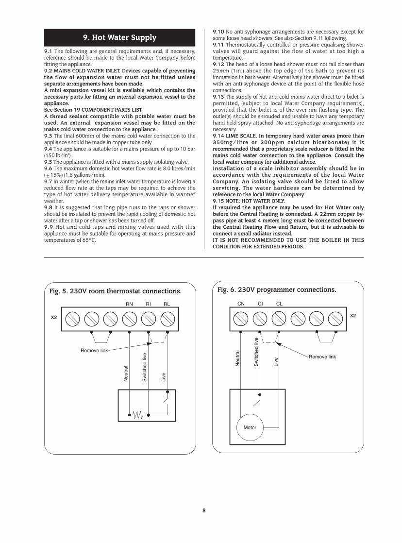
Fig. 5. 230V room thermostat connections. Fig. 6. 230V programmer connections.
RN RI
X2
Remove link
Neu
tral
Sw
itche
d liv
e
Live
RL CN
Motor
CI
X2
Neu
tral
Sw
itche
d liv
e
Live
CL
Remove link
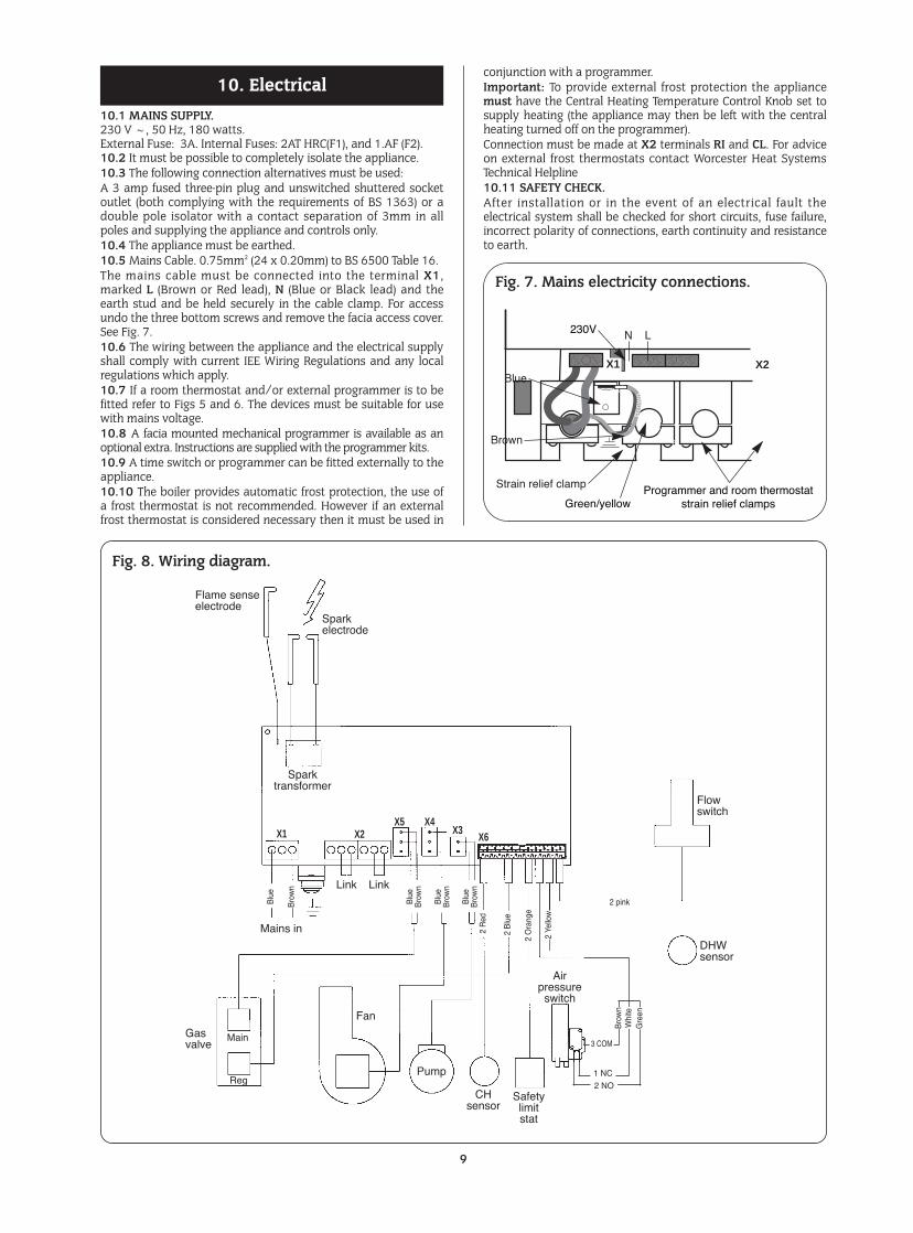
10.1 MAINS SUPPLY.230 V ~, 50 Hz, 180 watts.External Fuse: 3A. Internal Fuses: 2AT HRC(F1), and 1.AF (F2).10.2 It must be possible to completely isolate the appliance.10.3 The following connection alternatives must be used:A 3 amp fused three-pin plug and unswitched shuttered socketoutlet (both complying with the requirements of BS 1363) or adouble pole isolator with a contact separation of 3mm in allpoles and supplying the appliance and controls only.10.4 The appliance must be earthed.10.5 Mains Cable. 0.75mm2 (24 x 0.20mm) to BS 6500 Table 16.The mains cable must be connected into the terminal X1,marked L (Brown or Red lead), N (Blue or Black lead) and theearth stud and be held securely in the cable clamp. For accessundo the three bottom screws and remove the facia access cover.See Fig. 7.10.6 The wiring between the appliance and the electrical supplyshall comply with current IEE Wiring Regulations and any localregulations which apply.10.7 If a room thermostat and/or external programmer is to befitted refer to Figs 5 and 6. The devices must be suitable for usewith mains voltage.10.8 A facia mounted mechanical programmer is available as anoptional extra. Instructions are supplied with the programmer kits.10.9 A time switch or programmer can be fitted externally to theappliance.10.10 The boiler provides automatic frost protection, the use ofa frost thermostat is not recommended. However if an externalfrost thermostat is considered necessary then it must be used in
conjunction with a programmer.Important: To provide external frost protection the appliancemust have the Central Heating Temperature Control Knob set tosupply heating (the appliance may then be left with the centralheating turned off on the programmer).Connection must be made at X2 terminals RI and CL. For adviceon external frost thermostats contact Worcester Heat SystemsTechnical Helpline10.11 SAFETY CHECK.After installation or in the event of an electrical fault theelectrical system shall be checked for short circuits, fuse failure,incorrect polarity of connections, earth continuity and resistanceto earth.
10. Electrical
9
Fig. 7. Mains electricity connections.
Brown
Strain relief clamp
Blue
Bro
wn
Green/yellow
Green/yellowProgrammer and room thermostat
strain relief clamps
230V
X1 X2
N L
Blue
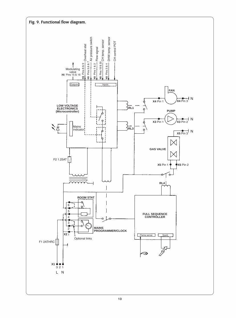
Fig. 8. Wiring diagram.
Safetylimitstat
DHWsensor
CHsensor
Gasvalve
Pump
Main
Reg
Flowswitch
Airpressure
switch
Sparktransformer
Mains in
2 pink
2 B
lue
2 R
ed
2 Ye
llow
2 O
rang
e
Bro
wn
Blu
e
Blu
e
Bro
wn
Blu
e
Bro
wn
Bro
wn
Blu
e
Link Link
X1 X2 X3X6
X5 X4
Flame senseelectrode
Sparkelectrode
Fan
Bro
wn
Whi
teG
reen
3 COM
1 NC
2 NO
10
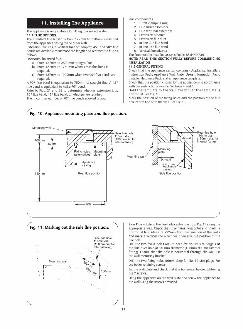
Fig. 9. Functional flow diagram.
F1 2ATHRC
F2 1.25AT
Optional linksSparkFlame sense
Outputs Inputs
Mainsindicator
Modulatingvalve
Ove
rhea
t sta
tX
6P
ins
8 &
9
X6 Pins 15 & 16
X6
Pin
s 5,
6 &
7
X6
Pin
s 1
& 2
X6
Pin
s 19
& 2
0
X6
Pin
s 3
& 4
Flo
w s
igna
l
CH
tem
p. s
enso
r
DH
W te
mp.
sen
sor
CH
con
trol
PO
T
Air
pres
sure
sw
itch
MAINSPROGRAMMER/CLOCK
FULL SEQUENCECONTROLLER
GAS VALVE
LOW VOLTAGEELECTRONICS
(Microcontroller)
ROOM STAT
X1
X2
3 2 1
1
2
3
4
6
5
RL1
X3 Pin 1 X3 Pin 2
X4 Pin 3
X5 Pin 3
X5 Pin 2X5 Pin 1
X4 Pin 1
FAN
PUMP
RL3
RL4
N
N
N
NL
Technical Helpline.
The appliance is only suitable for fitting to a sealed system.11.1 FLUE OPTIONS.The standard flue length is from 127mm to 350mm measuredfrom the appliance casing to the outer wall.Extension flue kits, a vertical take-off adapter, 45° and 90° fluebends are available to increase the length and redirect the flue asfollows.Horizontal balanced flue:
a) From 127mm to 2500mm straight flue.b) From 127mm to 1750mm when a 90° flue bend is
required.c) From 127mm to 1000mm when two 90° flue bends are
required.A 90° flue bend is equivalent to 750mm of straight flue. A 45°flue bend is equivalent to half a 90° bend.Refer to Figs. 21 and 22 to determine whether extension kits,90° flue bend, 45° flue bend, or adapters are required.The maximum number of 90° flue bends allowed is two.
Flue components1. Turret clamping ring.2. Flue turret assembly3. Flue terminal assembly4. Extension air duct5. Extension flue duct6. In-line 90° flue bend7. In-line 45° flue bend8. Vertical flue adapter
The flue must be installed as specified in BS 5440 Part 1.NOTE: READ THIS SECTION FULLY BEFORE COMMENCINGINSTALLATION11.2 GENERAL FITTING.Check that the appliance carton contains:- Appliance, InstallersInstruction Pack, Appliance Wall Plate, Users Information Pack,Installer Hardware Pack and an appliance template.Check that the position chosen for the appliance is in accordancewith the instructions given in Sections 4 and 5.Hold the template to the wall. Check that the template ishorizontal. See Fig. 10.Mark the position of the fixing holes and the position of the fluehole centre line onto the wall. See Fig. 10.
Side Flue – Extend the flue hole centre line from Fig. 11 along theappropriate wall. Check that it remains horizontal and mark ahorizontal line. Measure 222mm from the junction of the wallsand mark a vertical line which will then give the position of theflue hole.Drill the two fixing holes 60mm deep for No. 12 size plugs. Cutthe flue duct hole at 110mm diameter (150mm dia. for internalfitting). Ensure that the hole is horizontal through the wall. Fitthe wall mounting bracket.Drill the two fixing holes 60mm deep for No. 12 size plugs. Forthe boiler retaining screws.Fix the wall plate and check that it is horizontal before tighteningthe 2 screws.Hang the appliance on the wall plate and screw the appliance tothe wall using the screws provided.
11. Installing The Appliance
11
Fig. 10. Appliance mounting plate and flue position.
Fig. 11. Marking out the side flue position.
Mounting wall
Rear flue hole110mm dia.(150mm dia. forinternal fixing)
Side flue hole110mm dia.(150mm dia. forinternal fixing)
Appliancecasing
Mountingplate
Fixing holes(alternatives)
Mounting wall
Mountingplate
222mm
Side wall166mm
740mm
400mm
Rear flue position Side flue position
60mm
Appliancecasing
Rear flue hole110mm dia.(150mm dia. forinternal fixing)
Mounting wall
Side wall
222mm
166mm
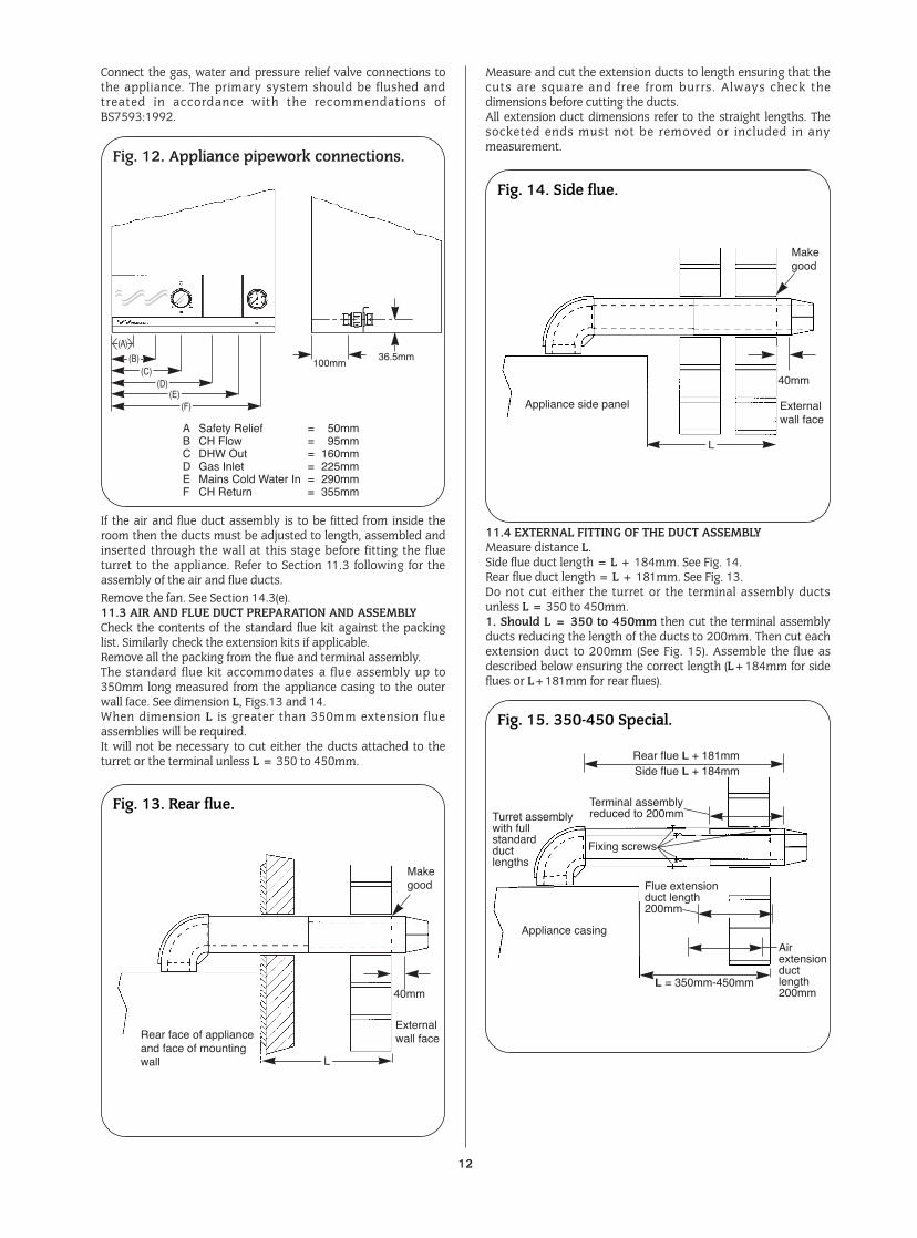
Connect the gas, water and pressure relief valve connections tothe appliance. The primary system should be flushed andtreated in accordance with the recommendations ofBS7593:1992.
If the air and flue duct assembly is to be fitted from inside theroom then the ducts must be adjusted to length, assembled andinserted through the wall at this stage before fitting the flueturret to the appliance. Refer to Section 11.3 following for theassembly of the air and flue ducts.Remove the fan. See Section 14.3(e).11.3 AIR AND FLUE DUCT PREPARATION AND ASSEMBLYCheck the contents of the standard flue kit against the packinglist. Similarly check the extension kits if applicable.Remove all the packing from the flue and terminal assembly.The standard flue kit accommodates a flue assembly up to350mm long measured from the appliance casing to the outerwall face. See dimension L, Figs.13 and 14.When dimension L is greater than 350mm extension flueassemblies will be required.It will not be necessary to cut either the ducts attached to theturret or the terminal unless L = 350 to 450mm.
Measure and cut the extension ducts to length ensuring that thecuts are square and free from burrs. Always check thedimensions before cutting the ducts.All extension duct dimensions refer to the straight lengths. Thesocketed ends must not be removed or included in anymeasurement.
11.4 EXTERNAL FITTING OF THE DUCT ASSEMBLYMeasure distance L.Side flue duct length = L + 184mm. See Fig. 14.Rear flue duct length = L + 181mm. See Fig. 13.Do not cut either the turret or the terminal assembly ductsunless L = 350 to 450mm.1. Should L = 350 to 450mm then cut the terminal assemblyducts reducing the length of the ducts to 200mm. Then cut eachextension duct to 200mm (See Fig. 15). Assemble the flue asdescribed below ensuring the correct length (L+184mm for sideflues or L+181mm for rear flues).
12
Fig. 13. Rear flue.
Fig. 14. Side flue.
Fig. 15. 350-450 Special.
Rear face of applianceand face of mountingwall
Externalwall face
40mm
Makegood
L
Appliance casing
Fixing screws
Flue extensionduct length200mm
Airextensionductlength200mm
Terminal assemblyreduced to 200mmTurret assembly
with fullstandardductlengths
Rear flue L + 181mmSide flue L + 184mm
L = 350mm-450mm
Appliance side panel Externalwall face
40mm
Makegood
L
Fig. 12. Appliance pipework connections.
(A)
100mm36.5mm(B)
(C)(D)
(E)(F)
A Safety Relief = 50mmB CH Flow = 95mmC DHW Out = 160mmD Gas Inlet = 225mmE Mains Cold Water In = 290mmF CH Return = 355mm
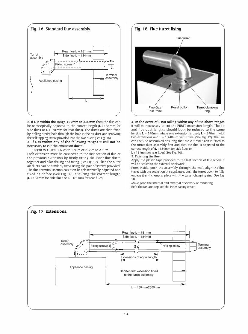
2. If L is within the range 127mm to 350mm then the flue canbe telescopically adjusted to the correct length (L+184mm forside flues or L+181mm for rear flues). The ducts are then fixedby drilling a pilot hole through the hole in the air duct and screwingthe self tapping screw provided into the two ducts (See Fig. 16).3. If L is within any of the following ranges it will not benecessary to cut the extension ducts:
0.88m to 1.10m, 1.63m to 1.85m or 2.38m to 2.50m. Each extension must be connected to the first section of flue orthe previous extension by firstly fitting the inner flue ductstogether and pilot drilling and fixing. (See Fig. 17). Then the outerair ducts can be similarly fixed using the pair of screws provided.The flue terminal section can then be telescopically adjusted andfixed as before (See Fig. 16) ensuring the correct length(L+184mm for side flues or L+181mm for rear flues).
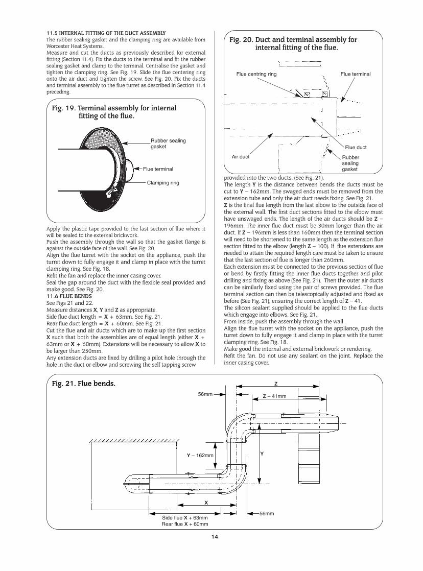
4. In the event of L not falling within any of the above rangesit will be necessary to cut the FIRST extension length. The airand flue duct lengths should both be reduced to the samelength: L – 240mm where one extension is used; L – 990mm withtwo extensions and L – 1,740mm with three. (See Fig. 17). The fluecan then be assembled ensuring that the cut extension is fitted tothe turret duct assembly first and that the flue is adjusted to thecorrect length of (L+184mm for side flues or L+181mm for rear flues) (See Fig. 16).5. Finishing the flueApply the plastic tape provided to the last section of flue where itwill be sealed to the external brickwork.From inside, push the assembly through the wall, align the flueturret with the socket on the appliance, push the turret down to fullyengage it and clamp in place with the turret clamping ring. See Fig.18.Make good the internal and external brickwork or rendering.Refit the fan and replace the inner casing cover.
13
Fig. 17. Extensions.
Fig. 18. Flue turret fixing.
Reset buttonFlue Gas Test Point
Flue turret
Turret clampingring
Rear flue L + 181mmSide flue L + 184mm
Appliance casing
Fixing screws Fixing screw
Turretassembly Terminal
assembly
L = 450mm-2500mm
Extensions of equal length
Shorten first extension fittedto the turret assembly
Fig. 16. Standard flue assembly.
Appliance casing
Fixing screw
Turretassembly
Terminalassembly
Rear flue L + 181mmSide flue L + 184mm
L
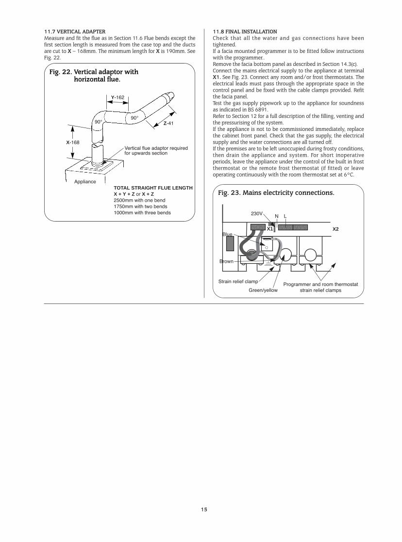
11.5 INTERNAL FITTING OF THE DUCT ASSEMBLYThe rubber sealing gasket and the clamping ring are available fromWorcester Heat Systems.Measure and cut the ducts as previously described for externalfitting (Section 11.4). Fix the ducts to the terminal and fit the rubbersealing gasket and clamp to the terminal. Centralise the gasket andtighten the clamping ring. See Fig. 19. Slide the flue centering ringonto the air duct and tighten the screw. See Fig. 20. Fix the ductsand terminal assembly to the flue turret as described in Section 11.4preceding.
Apply the plastic tape provided to the last section of flue where itwill be sealed to the external brickwork.Push the assembly through the wall so that the gasket flange isagainst the outside face of the wall. See Fig. 20.Align the flue turret with the socket on the appliance, push theturret down to fully engage it and clamp in place with the turretclamping ring. See Fig. 18.Refit the fan and replace the inner casing cover.Seal the gap around the duct with the flexible seal provided andmake good. See Fig. 20.11.6 FLUE BENDSSee Figs 21 and 22.Measure distances X, Y and Z as appropriate.Side flue duct length = X + 63mm. See Fig. 21.Rear flue duct length = X + 60mm. See Fig. 21.Cut the flue and air ducts which are to make up the first sectionX such that both the assemblies are of equal length (either X +63mm or X + 60mm). Extensions will be necessary to allow X tobe larger than 250mm.Any extension ducts are fixed by drilling a pilot hole through thehole in the duct or elbow and screwing the self tapping screw
provided into the two ducts. (See Fig. 21).The length Y is the distance between bends the ducts must becut to Y – 162mm. The swaged ends must be removed from theextension tube and only the air duct needs fixing. See Fig. 21.Z is the final flue length from the last elbow to the outside face ofthe external wall. The first duct sections fitted to the elbow musthave unswaged ends. The length of the air ducts should be Z –196mm. The inner flue duct must be 30mm longer than the airduct. If Z – 196mm is less than 160mm then the terminal sectionwill need to be shortened to the same length as the extension fluesection fitted to the elbow (length Z – 100). If flue extensions areneeded to attain the required length care must be taken to ensurethat the last section of flue is longer than 260mm.Each extension must be connected to the previous section of flueor bend by firstly fitting the inner flue ducts together and pilotdrilling and fixing as above (See Fig. 21). Then the outer air ductscan be similarly fixed using the pair of screws provided. The flueterminal section can then be telescopically adjusted and fixed asbefore (See Fig. 21), ensuring the correct length of Z – 41. The silicon sealant supplied should be applied to the flue ductswhich engage into elbows. See Fig. 21.From inside, push the assembly through the wallAlign the flue turret with the socket on the appliance, push theturret down to fully engage it and clamp in place with the turretclamping ring. See Fig. 18.Make good the internal and external brickwork or rendering.Refit the fan. Do not use any sealant on the joint. Replace theinner casing cover.
14
Fig. 21. Flue bends.56mm Z Ð 41mm
56mmSide flue X + 63mmRear flue X + 60mm
Z
Y
X
Y Ð 162mm
Fig. 19. Terminal assembly for internalfitting of the flue.
Flue centring ring Flue terminal
Flue duct
Rubbersealinggasket
Air duct
Rubber sealinggasket
Clamping ring
Flue terminal
Fig. 20. Duct and terminal assembly forinternal fitting of the flue.
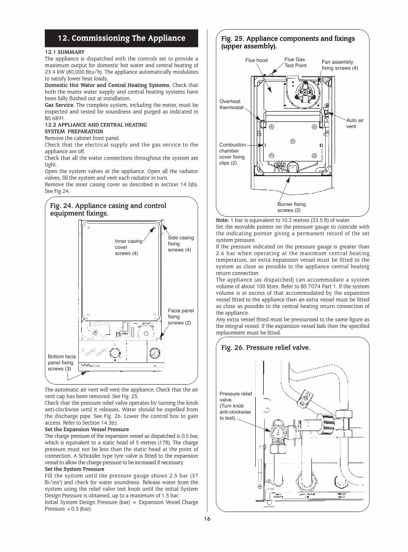
11.7 VERTICAL ADAPTERMeasure and fit the flue as in Section 11.6 Flue bends except thefirst section length is measured from the case top and the ductsare cut to X – 168mm. The minimum length for X is 190mm. SeeFig. 22.
11.8 FINAL INSTALLATIONCheck that all the water and gas connections have beentightened.If a facia mounted programmer is to be fitted follow instructionswith the programmer..Remove the facia bottom panel as described in Section 14.3(c).Connect the mains electrical supply to the appliance at terminalX1. See Fig. 23. Connect any room and/or frost thermostats. Theelectrical leads must pass through the appropriate space in thecontrol panel and be fixed with the cable clamps provided. Refitthe facia panel.Test the gas supply pipework up to the appliance for soundnessas indicated in BS 6891.Refer to Section 12 for a full description of the filling, venting andthe pressurising of the system.If the appliance is not to be commissioned immediately, replacethe cabinet front panel. Check that the gas supply, the electricalsupply and the water connections are all turned off.If the premises are to be left unoccupied during frosty conditions,then drain the appliance and system. For short inoperativeperiods, leave the appliance under the control of the built in frostthermostat or the remote frost thermostat (if fitted) or leaveoperating continuously with the room thermostat set at 6°C.
15
Fig. 22. Vertical adaptor withhorizontal flue.
X-168
Y-162
90¡90¡
Appliance
Vertical flue adaptor requiredfor upwards section
TOTAL STRAIGHT FLUE LENGTHX + Y + Z or X + Z2500mm with one bend1750mm with two bends1000mm with three bends
Z-41
Fig. 23. Mains electricity connections.
Brown
Strain relief clamp
Green/yellowProgrammer and room thermostat
strain relief clamps
230V
X1 X2
N L
Blue
12.1 SUMMARYThe appliance is dispatched with the controls set to provide amaximum output for domestic hot water and central heating of23.4 kW (80,000 Btu/h). The appliance automatically modulatesto satisfy lower heat loads.Domestic Hot Water and Central Heating Systems. Check thatboth the mains water supply and central heating systems havebeen fully flushed out at installation.Gas Service. The complete system, including the meter, must beinspected and tested for soundness and purged as indicated inBS 6891.12.2 APPLIANCE AND CENTRAL HEATINGSYSTEM PREPARATIONRemove the cabinet front panel.Check that the electrical supply and the gas service to theappliance are off.Check that all the water connections throughout the system aretight.Open the system valves at the appliance. Open all the radiatorvalves, fill the system and vent each radiator in turn.Remove the inner casing cover as described in section 14.3(b).See Fig 24.
The automatic air vent will vent the appliance. Check that the airvent cap has been removed. See Fig. 25.Check that the pressure relief valve operates by turning the knobanti-clockwise until it releases. Water should be expelled fromthe discharge pipe. See Fig. 26. Lower the control box to gainaccess. Refer to Section 14.3(c).Set the Expansion Vessel PressureThe charge pressure of the expansion vessel as dispatched is 0.5 bar,which is equivalent to a static head of 5 metres (17ft). The chargepressure must not be less than the static head at the point ofconnection. A Schraider type tyre valve is fitted to the expansionvessel to allow the charge pressure to be increased if necessary.Set the System PressureFill the system until the pressure gauge shows 2.5 bar (37lb/ins2) and check for water soundness. Release water from thesystem using the relief valve test knob until the initial SystemDesign Pressure is obtained, up to a maximum of 1.5 bar.Initial System Design Pressure (bar) = Expansion Vessel ChargePressure +0.3 (bar).
Note: 1 bar is equivalent to 10.2 metres (33.5 ft) of water.Set the movable pointer on the pressure gauge to coincide withthe indicating pointer giving a permanent record of the setsystem pressure.If the pressure indicated on the pressure gauge is greater than2.6 bar when operating at the maximum central heatingtemperature, an extra expansion vessel must be fitted to thesystem as close as possible to the appliance central heatingreturn connection.The appliance (as dispatched) can accommodate a systemvolume of about 100 litres. Refer to BS 7074 Part 1. If the systemvolume is in excess of that accommodated by the expansionvessel fitted to the appliance then an extra vessel must be fittedas close as possible to the central heating return connection ofthe appliance.Any extra vessel fitted must be pressurised to the same figure asthe integral vessel. If the expansion vessel fails then the specifiedreplacement must be fitted.
12. Commissioning The Appliance
16
Fig. 25. Appliance components and fixings(upper assembly).
Flue hood
Overheatthermostat
Burner fixingscrews (2)
Combustionchambercover fixingclips (2)
Auto airvent
Fan assemblyfixing screws (4)
Flue Gas Test Point
Fig. 24. Appliance casing and controlequipment fixings.
Inner casingcoverscrews (4)
Side casingfixingscrews (4)
Facia panelfixingscrews (2)
Bottom faciapanel fixingscrews (3)
Fig. 26. Pressure relief valve.
Pressure reliefvalve.(Turn knobanti-clockwiseto test).
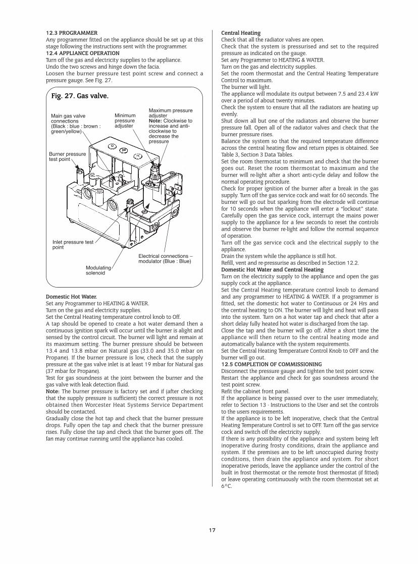
12.3 PROGRAMMERAny programmer fitted on the appliance should be set up at thisstage following the instructions sent with the programmer.12.4 APPLIANCE OPERATIONTurn off the gas and electricity supplies to the appliance.Undo the two screws and hinge down the facia.Loosen the burner pressure test point screw and connect apressure gauge. See Fig. 27.
Domestic Hot Water.Set any Programmer to HEATING & WATER.Turn on the gas and electricity supplies.Set the Central Heating temperature control knob to Off.A tap should be opened to create a hot water demand then acontinuous ignition spark will occur until the burner is alight andsensed by the control circuit. The burner will light and remain atits maximum setting. The burner pressure should be between13.4 and 13.8 mbar on Natural gas (33.0 and 35.0 mbar onPropane). If the burner pressure is low, check that the supplypressure at the gas valve inlet is at least 19 mbar for Natural gas(37 mbar for Propane).Test for gas soundness at the joint between the burner and thegas valve with leak detection fluid.Note: The burner pressure is factory set and if (after checkingthat the supply pressure is sufficient) the correct pressure is notobtained then Worcester Heat Systems Service Departmentshould be contacted.Gradually close the hot tap and check that the burner pressuredrops. Fully open the tap and check that the burner pressurerises. Fully close the tap and check that the burner goes off. Thefan may continue running until the appliance has cooled.
Central HeatingCheck that all the radiator valves are open.Check that the system is pressurised and set to the requiredpressure as indicated on the gauge.Set any Programmer to HEATING & WATER.Turn on the gas and electricity supplies.Set the room thermostat and the Central Heating TemperatureControl to maximum.The burner will light.The appliance will modulate its output between 7.5 and 23.4 kWover a period of about twenty minutes.Check the system to ensure that all the radiators are heating upevenly.Shut down all but one of the radiators and observe the burnerpressure fall. Open all of the radiator valves and check that theburner pressure rises.Balance the system so that the required temperature differenceacross the central heating flow and return pipes is obtained. SeeTable 3, Section 3 Data Tables.Set the room thermostat to minimum and check that the burnergoes out. Reset the room thermostat to maximum and theburner will re-light after a short anti-cycle delay and follow thenormal operating procedure.Check for proper ignition of the burner after a break in the gassupply. Turn off the gas service cock and wait for 60 seconds. Theburner will go out but sparking from the electrode will continuefor 10 seconds when the appliance will enter a “lockout” state.Carefully open the gas service cock, interrupt the mains powersupply to the appliance for a few seconds to reset the controlsand observe the burner re-light and follow the normal sequenceof operation.Turn off the gas service cock and the electrical supply to theappliance.Drain the system while the appliance is still hot.Refill, vent and re-pressurise as described in Section 12.2.Domestic Hot Water and Central HeatingTurn on the electricity supply to the appliance and open the gassupply cock at the appliance.Set the Central Heating temperature control knob to demandand any programmer to HEATING & WATER. If a programmer isfitted, set the domestic hot water to Continuous or 24 Hrs andthe central heating to ON. The burner will light and heat will passinto the system. Turn on a hot water tap and check that after ashort delay fully heated hot water is discharged from the tap.Close the tap and the burner will go off. After a short time theappliance will then return to the central heating mode andautomatically balance with the system requirements.Set the Central Heating Temperature Control Knob to OFF and theburner will go out.12.5 COMPLETION OF COMMISSIONINGDisconnect the pressure gauge and tighten the test point screw.Restart the appliance and check for gas soundness around thetest point screw.Refit the cabinet front panel.If the appliance is being passed over to the user immediately,refer to Section 13 - Instructions to the User and set the controlsto the users requirements.If the appliance is to be left inoperative, check that the CentralHeating Temperature Control is set to OFF. Turn off the gas servicecock and switch off the electricity supply.If there is any possibility of the appliance and system being leftinoperative during frosty conditions, drain the appliance andsystem. If the premises are to be left unoccupied during frostyconditions, then drain the appliance and system. For shortinoperative periods, leave the appliance under the control of thebuilt in frost thermostat or the remote frost thermostat (if fitted)or leave operating continuously with the room thermostat set at6°C.
17
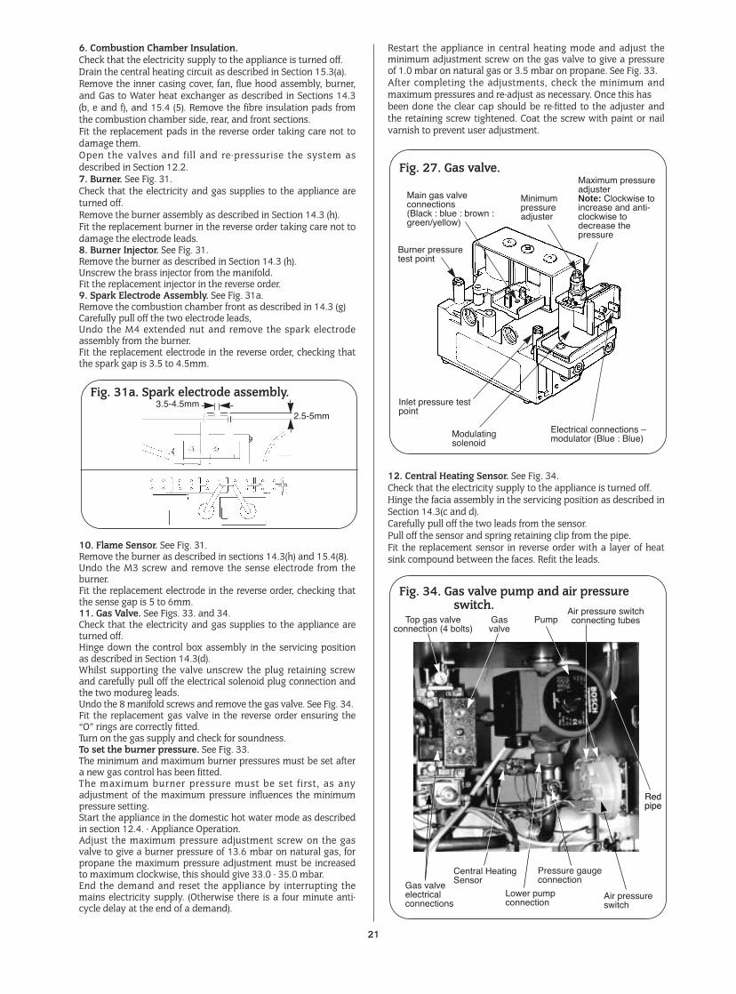
Fig. 27. Gas valve.
Main gas valveconnections(Black : blue : brown :green/yellow)
Burner pressuretest point
Inlet pressure testpoint
Electrical connections Ðmodulator (Blue : Blue)
Modulatingsolenoid
Minimumpressureadjuster
Maximum pressureadjusterNote: Clockwise toincrease and anti-clockwise todecrease thepressure
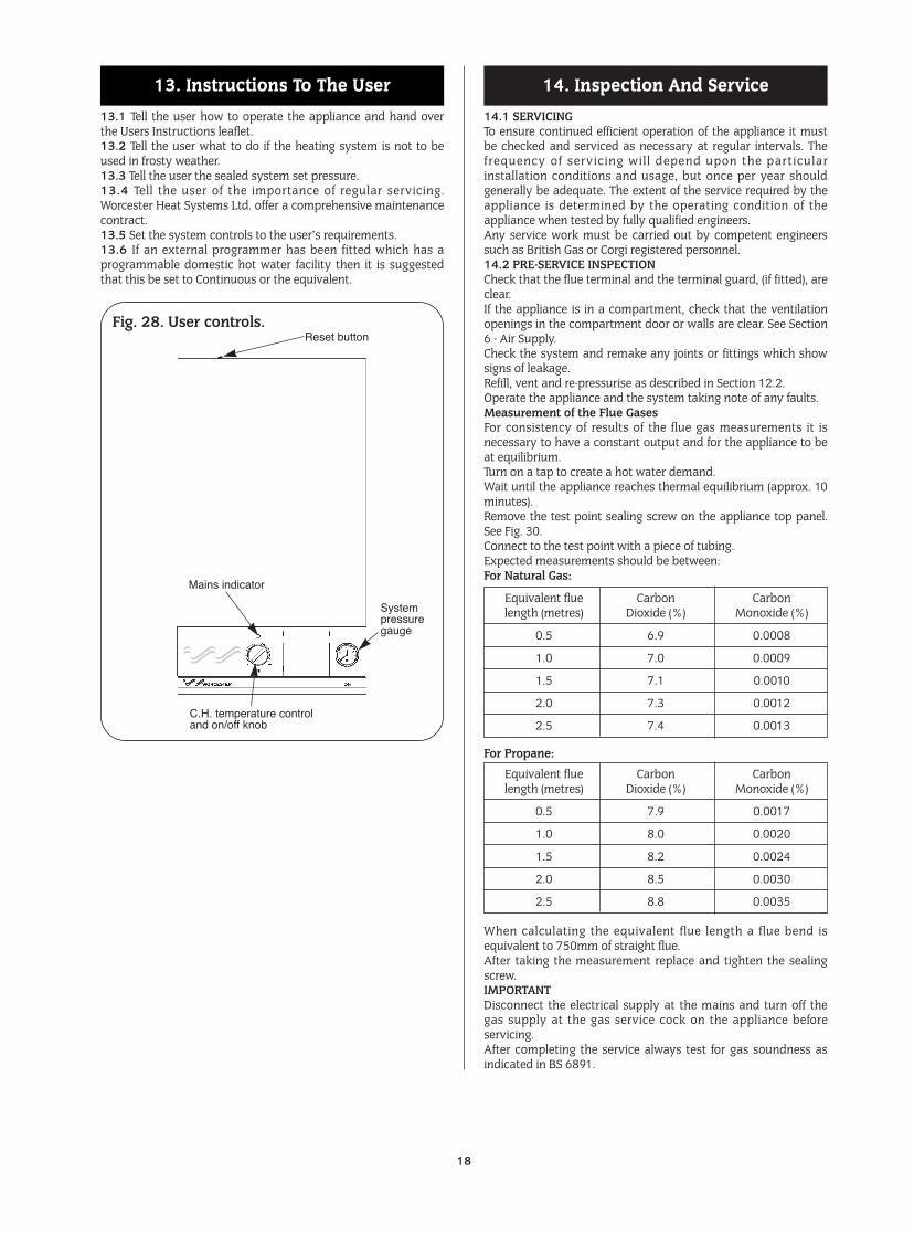
13.1 Tell the user how to operate the appliance and hand overthe Users Instructions leaflet.13.2 Tell the user what to do if the heating system is not to beused in frosty weather.13.3 Tell the user the sealed system set pressure.13.4 Tell the user of the importance of regular servicing.Worcester Heat Systems Ltd. offer a comprehensive maintenancecontract.13.5 Set the system controls to the user’s requirements.13.6 If an external programmer has been fitted which has aprogrammable domestic hot water facility then it is suggestedthat this be set to Continuous or the equivalent.
14.1 SERVICINGTo ensure continued efficient operation of the appliance it mustbe checked and serviced as necessary at regular intervals. Thefrequency of servicing wil l depend upon the particularinstallation conditions and usage, but once per year shouldgenerally be adequate. The extent of the service required by theappliance is determined by the operating condition of theappliance when tested by fully qualified engineers.Any service work must be carried out by competent engineerssuch as British Gas or Corgi registered personnel.14.2 PRE-SERVICE INSPECTIONCheck that the flue terminal and the terminal guard, (if fitted), areclear.If the appliance is in a compartment, check that the ventilationopenings in the compartment door or walls are clear. See Section6 - Air Supply.Check the system and remake any joints or fittings which showsigns of leakage.Refill, vent and re-pressurise as described in Section 12.2.Operate the appliance and the system taking note of any faults.Measurement of the Flue GasesFor consistency of results of the flue gas measurements it isnecessary to have a constant output and for the appliance to beat equilibrium.Turn on a tap to create a hot water demand.Wait until the appliance reaches thermal equilibrium (approx. 10minutes).Remove the test point sealing screw on the appliance top panel.See Fig. 30.Connect to the test point with a piece of tubing.Expected measurements should be between:For Natural Gas:
For Propane:
When calculating the equivalent flue length a flue bend isequivalent to 750mm of straight flue.After taking the measurement replace and tighten the sealingscrew.IMPORTANTDisconnect the electrical supply at the mains and turn off thegas supply at the gas service cock on the appliance beforeservicing.After completing the service always test for gas soundness asindicated in BS 6891.
14. Inspection And Service13. Instructions To The User
18
Equivalent flue Carbon Carbonlength (metres) Dioxide (%) Monoxide (%)
0.5 6.9 0.0008
1.0 7.0 0.0009
1.5 7.1 0.0010
2.0 7.3 0.0012
2.5 7.4 0.0013
Equivalent flue Carbon Carbonlength (metres) Dioxide (%) Monoxide (%)
0.5 7.9 0.0017
1.0 8.0 0.0020
1.5 8.2 0.0024
2.0 8.5 0.0030
2.5 8.8 0.0035
Fig. 28. User controls.Reset button
Mains indicator
C.H. temperature controland on/off knob
Systempressuregauge
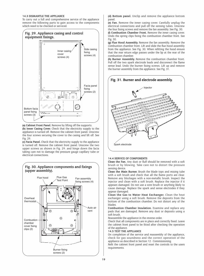
14.3 DISMANTLE THE APPLIANCETo carry out a full and comprehensive service of the applianceremove the following parts to gain access to the componentswhich need to be checked or serviced.
(a) Cabinet Front Panel. Remove by lifting off the supports.(b) Inner Casing Cover. Check that the electricity supply to theappliance is turned off. Remove the cabinet front panel. Unscrewthe four screws securing the cover to the casing and lift off. SeeFig. 29.(c) Facia Panel. Check that the electricity supply to the applianceis turned off. Remove the cabinet front panel. Unscrew the twoupper screws as shown in Fig. 29. and hinge down the faciataking care not to damage the pressure gauge capillary tube orelectrical connections.
(d) Bottom panel. Unclip and remove the appliance bottompanel.(e) Fan. Remove the inner casing cover. Carefully unplug theelectrical connections and pull off the sensing tubes. Unscrewthe four fixing screws and remove the fan assembly. See Fig. 30.(f) Combustion Chamber Front. Remove the inner casing cover.Undo the spring clips fixing the combustion chamber front. SeeFig. 30.(g) Flue Hood Assembly. Remove the fan assembly. Remove thecombustion chamber front. Lift and slide the flue hood assemblyfrom the appliance. See Fig. 30. When refitting the hood ensurethat the rear return edge passes under the lip at the rear of thecombustion chamber.(h) Burner Assembly. Remove the combustion chamber front.Pull off the two spark electrode leads and disconnect the flamesense lead. Undo the burner fixing screws. Lift up and removethe burner assembly from the appliance. See Fig. 31.
14.4 SERVICE OF COMPONENTSClean the Fan. Any dust or fluff should be removed with a softbrush or by blowing. Take care not to distort the pressuresensing device.Clean the Main Burner. Brush the blade tops and mixing tubewith a soft brush and check that all the flame ports are clear.Remove any blockages with a non-metallic brush. Inspect theinjector and clean with a soft brush. Replace the injector if itappears damaged. Do not use a wire brush or anything likely tocause damage. Replace the spark and sense electrodes if theyappear damaged.Clean the Gas to Water Heat Exchanger. Clean the heatexchanger using a soft brush. Remove the deposits from thebottom of the combustion chamber. Do not distort any of theblades.Combustion Chamber Insulation. Examine and replace anypads that are damaged. Remove any dust or deposits using asoft brush.Reassemble the appliance in the reverse order.Check that all components are in place and correctly fixed. Leavethe cabinet front panel to be fitted after checking the operationof the appliance.14.5 TEST THE APPLIANCEOn completion of the service and reassembly of the appliance,check for gas soundness and the correct operation of theappliance as described in Section 12 - Commissioning.Refit the cabinet front panel and reset the controls to the usersrequirements.
19
Fig. 31. Burner and electrode assembly.
Spark electrode
Injector
Fig. 30. Appliance components and fixings(upper assembly).
Flue hood
Overheatthermostat
Burner fixingscrews (2)
Combustionchambercover fixingclips (2)
Auto airvent
Fan assemblyfixing screws (4)
Flue Gas Test Point
Fig. 29. Appliance casing and controlequipment fixings.
Inner casingcoverscrews (4)
Side casingfixingscrews (4)
Facia panelfixingscrews (2)
Bottom faciapanel fixingscrews (3)
15.1 IMPORTANTSwitch off the electricity and gas supplies before replacing anycomponents. After the replacement of any components, checkfor gas soundness where relevant and carry out functionalchecks as described in Section 12 - Commissioning15.2 COMPONENT ACCESSTo replace components it is necessary to remove one or moresections of the cabinet and cover plates within the appliance asdescribed in Section 14.3. The facia panel may also need to behinged down as described in Section 14.3 (c).15.3 DRAINING THE APPLIANCECheck that the electricity supply to the appliance is turned off.Before removing any component holding water it is importantthat as much water as possible is removed from the appliance.(a) Central Heating Circuit. Turn off the central heating flow andreturn valves at the appliance. Open the pressure relief valve,make sure that the dust cap on the auto air vent is removed. SeeFig. 30. Close the pressure relief valve when the flow hasstopped. Some water will remain in the expansion vessel, pumpand Gas to Water heat exchangers and extra care must be takenwhen removing these components.(b) Domestic Hot Water Circuit. Turn off the mains cold supplyvalve at the appliance and open the lowest hot water tap. Aquantity of water will remain in the Gas to Water heat exchanger,extra care must be taken when removing this component.15.4 COMPONENT REPLACEMENT1. Automatic Air Vent. See Figs. 30. and 32.Remove the inner casing cover as described in Section 14.3 (b).Drain the central heating circuit as described in Section 15.3 (a).Unscrew air vent from the heat exchanger.Fit the replacement assembly ensuring thread sealant is appliedand the dust cap is removed.Open the valves and fill and re-pressurise the system asdescribed in Section 12.2.
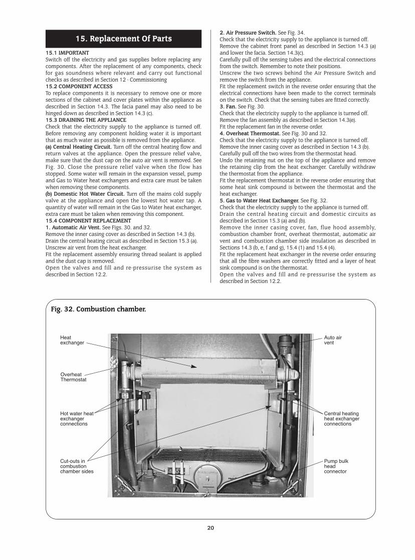
2. Air Pressure Switch. See Fig. 34.Check that the electricity supply to the appliance is turned off.Remove the cabinet front panel as described in Section 14.3 (a)and lower the facia. Section 14.3(c).Carefully pull off the sensing tubes and the electrical connectionsfrom the switch. Remember to note their positions.Unscrew the two screws behind the Air Pressure Switch andremove the switch from the appliance.Fit the replacement switch in the reverse order ensuring that theelectrical connections have been made to the correct terminalson the switch. Check that the sensing tubes are fitted correctly.3. Fan. See Fig. 30.Check that the electricity supply to the appliance is turned off.Remove the fan assembly as described in Section 14.3(e).Fit the replacement fan in the reverse order.4. Overheat Thermostat. See Fig. 30 and 32.Check that the electricity supply to the appliance is turned off.Remove the inner casing cover as described in Section 14.3 (b).Carefully pull off the two wires from the thermostat head.Undo the retaining nut on the top of the appliance and removethe retaining clip from the heat exchanger. Carefully withdrawthe thermostat from the appliance.Fit the replacement thermostat in the reverse order ensuring thatsome heat sink compound is between the thermostat and theheat exchanger.5. Gas to Water Heat Exchanger. See Fig. 32.Check that the electricity supply to the appliance is turned off.Drain the central heating circuit and domestic circuits asdescribed in Section 15.3 (a) and (b).Remove the inner casing cover, fan, flue hood assembly,combustion chamber front, overheat thermostat, automatic airvent and combustion chamber side insulation as described inSections 14.3 (b, e, f and g), 15.4 (1) and 15.4 (4).Fit the replacement heat exchanger in the reverse order ensuringthat all the fibre washers are correctly fitted and a layer of heatsink compound is on the thermostat.Open the valves and fill and re-pressurise the system asdescribed in Section 12.2.
15. Replacement Of Parts
20
Fig. 32. Combustion chamber.
Heatexchanger
OverheatThermostat
Hot water heatexchangerconnections
Cut-outs incombustionchamber sides
Pump bulkheadconnector
Central heatingheat exchangerconnections
Auto airvent
6. Combustion Chamber Insulation.Check that the electricity supply to the appliance is turned off.Drain the central heating circuit as described in Section 15.3(a).Remove the inner casing cover, fan, flue hood assembly, burner,and Gas to Water heat exchanger as described in Sections 14.3(b, e and f), and 15.4 (5). Remove the fibre insulation pads fromthe combustion chamber side, rear, and front sections.Fit the replacement pads in the reverse order taking care not todamage them.Open the valves and fill and re-pressurise the system asdescribed in Section 12.2.7. Burner. See Fig. 31.Check that the electricity and gas supplies to the appliance areturned off.Remove the burner assembly as described in Section 14.3 (h).Fit the replacement burner in the reverse order taking care not todamage the electrode leads.8. Burner Injector. See Fig. 31.Remove the burner as described in Section 14.3 (h).Unscrew the brass injector from the manifold.Fit the replacement injector in the reverse order.9. Spark Electrode Assembly. See Fig. 31a.Remove the combustion chamber front as described in 14.3 (g)Carefully pull off the two electrode leads,Undo the M4 extended nut and remove the spark electrodeassembly from the burner.Fit the replacement electrode in the reverse order, checking thatthe spark gap is 3.5 to 4.5mm.
10. Flame Sensor. See Fig. 31.Remove the burner as described in sections 14.3(h) and 15.4(8).Undo the M3 screw and remove the sense electrode from theburner.Fit the replacement electrode in the reverse order, checking thatthe sense gap is 5 to 6mm.11. Gas Valve. See Figs. 33. and 34.Check that the electricity and gas supplies to the appliance areturned off.Hinge down the control box assembly in the servicing positionas described in Section 14.3(d).Whilst supporting the valve unscrew the plug retaining screwand carefully pull off the electrical solenoid plug connection andthe two modureg leads.Undo the 8 manifold screws and remove the gas valve. See Fig. 34.Fit the replacement gas valve in the reverse order ensuring the“O” rings are correctly fitted.Turn on the gas supply and check for soundness.To set the burner pressure. See Fig. 33.The minimum and maximum burner pressures must be set aftera new gas control has been fitted.The maximum burner pressure must be set first, as anyadjustment of the maximum pressure influences the minimumpressure setting.Start the appliance in the domestic hot water mode as describedin section 12.4. - Appliance Operation.Adjust the maximum pressure adjustment screw on the gasvalve to give a burner pressure of 13.6 mbar on natural gas, forpropane the maximum pressure adjustment must be increasedto maximum clockwise, this should give 33.0 - 35.0 mbar.End the demand and reset the appliance by interrupting themains electricity supply. (Otherwise there is a four minute anti-cycle delay at the end of a demand).
Restart the appliance in central heating mode and adjust theminimum adjustment screw on the gas valve to give a pressureof 1.0 mbar on natural gas or 3.5 mbar on propane. See Fig. 33.After completing the adjustments, check the minimum andmaximum pressures and re-adjust as necessary. Once this has been done the clear cap should be re-fitted to the adjuster andthe retaining screw tightened. Coat the screw with paint or nailvarnish to prevent user adjustment.
12. Central Heating Sensor. See Fig. 34.Check that the electricity supply to the appliance is turned off.Hinge the facia assembly in the servicing position as described inSection 14.3(c and d).Carefully pull off the two leads from the sensor.Pull off the sensor and spring retaining clip from the pipe.Fit the replacement sensor in reverse order with a layer of heatsink compound between the faces. Refit the leads.
21
Fig. 34. Gas valve pump and air pressure switch.
Lower pumpconnection
Gas valveelectricalconnections
Pressure gaugeconnection
Central HeatingSensor
Air pressureswitch
Air pressure switchconnecting tubesPumpGas
valveTop gas valve
connection (4 bolts)
Redpipe
Fig. 27. Gas valve.
Main gas valveconnections(Black : blue : brown :green/yellow)
Burner pressuretest point
Inlet pressure testpoint
Electrical connections Ðmodulator (Blue : Blue)Modulating
solenoid
Minimumpressureadjuster
Maximum pressureadjusterNote: Clockwise toincrease and anti-clockwise todecrease thepressure
Fig. 31a. Spark electrode assembly.3.5-4.5mm
2.5-5mm
13. Domestic Hot Water Sensor.Check that the electricity supply to the appliance is turned off.Hinge the facia assembly in the servicing position as described inSection 14.3(c and d).Carefully pull off the two leads from the sensor.Undo and remove the clamping screw.Pull off the sensor and spring retaining clip from the pipe.Fit the replacement sensor in the reverse order ensuring a layerof heat sink compound is between the faces. Refit the leads.14. Circulating Pump. See Figs. 32 and 34.Check that the electricity supply to the appliance is turned off.Drain the central heating circuit as described in Section 15.3(a).Hinge the facia assembly in the servicing position as described inSection 14.3(c).Undo the two union nuts and the pipe to the expansion vessel,remove the pump from the pipe-work. Support the pump andremove the electrical cover.Disconnect the electrical wires taking note of their positions.Fit the replacement pump in the reverse order using new sealingwashers.(Alternatively replace the pump head only by removing the fourAllen screws on the pump, remove the head and support whilstremoving the electrical connections. Refit the new head).Open the valves and fill and re-pressurise the system asdescribed in Section 12.2Note: The direction of flow should be upwards. The speed shouldalways be set to maximum.15. Expansion Vessel.Drain the central heating circuit as described in Section 15.3(a).Isolate the gas supply at the mains.Then either fit a separate expansion vessel on the central heatingreturn to the appliance or replace the existing vessel asdescribed below.Drain the domestic circuit as described in Section 15.3(b).Disconnect the flue system at the boiler.Disconnect the appliance pipework at the appliance entry pointsensuring precautions are taken to cope with any waterremaining in the appliance.Remove the appliance from the wall.Disconnect the expansion vessel from the appliance by undoingthe fitting nut at it’s base.Fit the replacement vessel in the reverse order.Open the valves and fill and re-pressurise the system asdescribed in Section 12.2
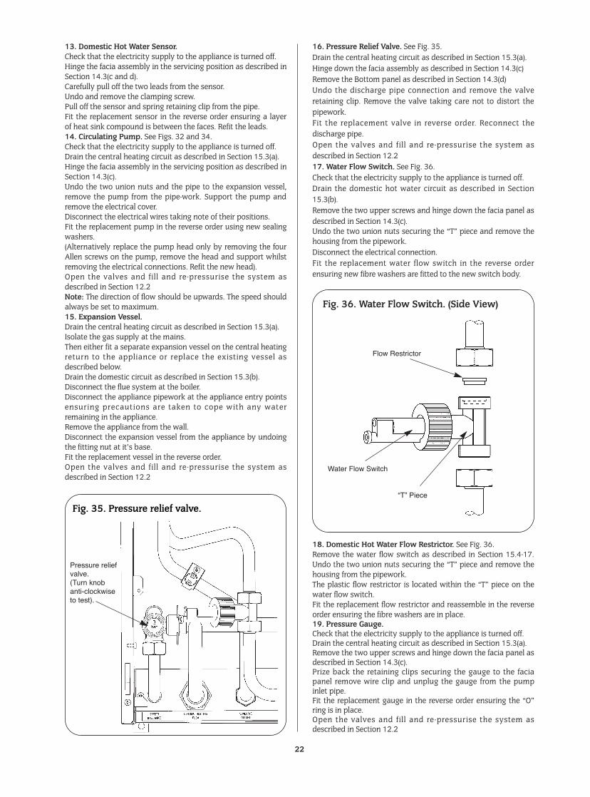
16. Pressure Relief Valve. See Fig. 35.Drain the central heating circuit as described in Section 15.3(a).Hinge down the facia assembly as described in Section 14.3(c)Remove the Bottom panel as described in Section 14.3(d)Undo the discharge pipe connection and remove the valveretaining clip. Remove the valve taking care not to distort thepipework.Fit the replacement valve in reverse order. Reconnect thedischarge pipe.Open the valves and fill and re-pressurise the system asdescribed in Section 12.217. Water Flow Switch. See Fig. 36.Check that the electricity supply to the appliance is turned off.Drain the domestic hot water circuit as described in Section15.3(b).Remove the two upper screws and hinge down the facia panel asdescribed in Section 14.3(c).Undo the two union nuts securing the “T” piece and remove thehousing from the pipework.Disconnect the electrical connection.Fit the replacement water flow switch in the reverse orderensuring new fibre washers are fitted to the new switch body.
18. Domestic Hot Water Flow Restrictor. See Fig. 36.Remove the water flow switch as described in Section 15.4-17.Undo the two union nuts securing the “T” piece and remove thehousing from the pipework.The plastic flow restrictor is located within the “T” piece on thewater flow switch.Fit the replacement flow restrictor and reassemble in the reverseorder ensuring the fibre washers are in place.19. Pressure Gauge.Check that the electricity supply to the appliance is turned off.Drain the central heating circuit as described in Section 15.3(a).Remove the two upper screws and hinge down the facia panel asdescribed in Section 14.3(c).Prize back the retaining clips securing the gauge to the faciapanel remove wire clip and unplug the gauge from the pumpinlet pipe.Fit the replacement gauge in the reverse order ensuring the “O”ring is in place.Open the valves and fill and re-pressurise the system asdescribed in Section 12.2
22
Fig. 35. Pressure relief valve.
Pressure reliefvalve.(Turn knobanti-clockwiseto test).
Fig. 36. Water Flow Switch. (Side View)
Flow Restrictor
Water Flow Switch
ÒTÓ Piece
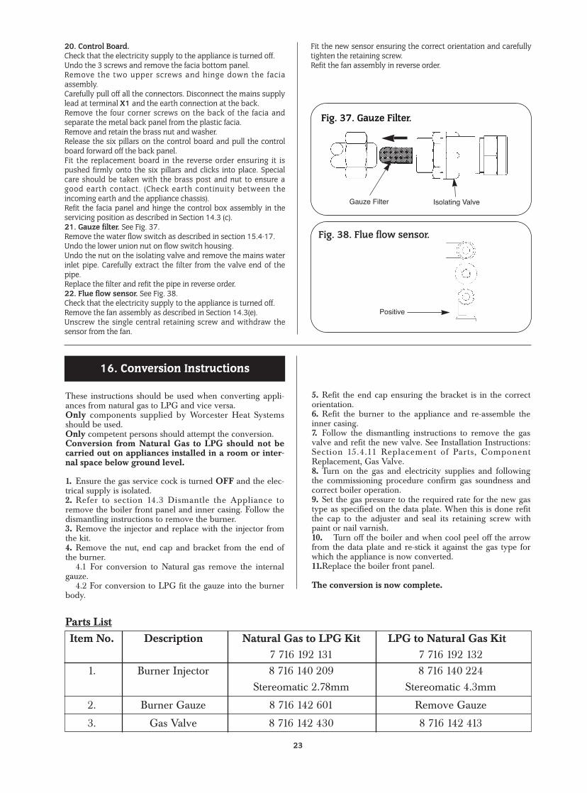
20. Control Board.Check that the electricity supply to the appliance is turned off.Undo the 3 screws and remove the facia bottom panel.Remove the two upper screws and hinge down the faciaassembly.Carefully pull off all the connectors. Disconnect the mains supplylead at terminal X1 and the earth connection at the back.Remove the four corner screws on the back of the facia andseparate the metal back panel from the plastic facia.Remove and retain the brass nut and washer.Release the six pillars on the control board and pull the controlboard forward off the back panel.Fit the replacement board in the reverse order ensuring it ispushed firmly onto the six pillars and clicks into place. Specialcare should be taken with the brass post and nut to ensure agood earth contact. (Check earth continuity between theincoming earth and the appliance chassis).Refit the facia panel and hinge the control box assembly in theservicing position as described in Section 14.3 (c).21. Gauze filter. See Fig. 37.Remove the water flow switch as described in section 15.4-17.Undo the lower union nut on flow switch housing.Undo the nut on the isolating valve and remove the mains waterinlet pipe. Carefully extract the filter from the valve end of thepipe.Replace the filter and refit the pipe in reverse order.22. Flue flow sensor. See Fig. 38.Check that the electricity supply to the appliance is turned off. Remove the fan assembly as described in Section 14.3(e).Unscrew the single central retaining screw and withdraw thesensor from the fan.
Fit the new sensor ensuring the correct orientation and carefullytighten the retaining screw.Refit the fan assembly in reverse order.
23
Fig. 37. Gauze Filter.
Gauze Filter
Positive
Isolating Valve
These instructions should be used when converting appli-ances from natural gas to LPG and vice versa.Only components supplied by Worcester Heat Systemsshould be used.Only competent persons should attempt the conversion.Conversion from Natural Gas to LPG should not becarried out on appliances installed in a room or inter-nal space below ground level.
1. Ensure the gas service cock is turned OFF and the elec-trical supply is isolated.2. Refer to section 14.3 Dismantle the Appliance toremove the boiler front panel and inner casing. Follow thedismantling instructions to remove the burner.3. Remove the injector and replace with the injector fromthe kit.4. Remove the nut, end cap and bracket from the end ofthe burner.
4.1 For conversion to Natural gas remove the internalgauze.
4.2 For conversion to LPG fit the gauze into the burnerbody.
5. Refit the end cap ensuring the bracket is in the correctorientation.6. Refit the burner to the appliance and re-assemble theinner casing.7. Follow the dismantling instructions to remove the gasvalve and refit the new valve. See Installation Instructions:Section 15.4.11 Replacement of Parts, ComponentReplacement, Gas Valve.8. Turn on the gas and electricity supplies and followingthe commissioning procedure confirm gas soundness andcorrect boiler operation.9. Set the gas pressure to the required rate for the new gastype as specified on the data plate. When this is done refitthe cap to the adjuster and seal its retaining screw withpaint or nail varnish.10. Turn off the boiler and when cool peel off the arrowfrom the data plate and re-stick it against the gas type forwhich the appliance is now converted.11.Replace the boiler front panel.
The conversion is now complete.
16. Conversion Instructions
Item No. Description Natural Gas to LPG Kit LPG to Natural Gas Kit7 716 192 131 7 716 192 132
1. Burner Injector 8 716 140 209 8 716 140 224Stereomatic 2.78mm Stereomatic 4.3mm
2. Burner Gauze 8 716 142 601 Remove Gauze
3. Gas Valve 8 716 142 430 8 716 142 413
Parts List
Fig. 38. Flue flow sensor.
24
End
of a
dom
estic
hot w
ater
ove
rrun
Esca
pe p
ause
by
rese
ttin
g th
e m
ains
elec
tric
ity s
uppl
yOF
F-ON
Anti-
cycl
e de
lay
Mai
n ga
s va
lve
OFF
6
EIT
HE
R
AU
TOM
ATIC
STA
RT-
UP
SE
QU
EN
CE
1. C
entr
al H
eatin
g M
ode N
OPA
SS
PRES
ENT
PR
ES
EN
TA
BS
EN
TA
BS
EN
TFA
IL
YE
S
Cent
ral h
eatin
gte
mpe
ratu
re 5
°Cab
ove
set p
oint
Oper
atin
g Sw
itch
(or p
rogr
amm
er)
OFF
Fan
over
run
4 m
inut
es
Cont
inue
pu
mp
over
run
for 6
sec
s pu
mp
puls
e af
ter
2 m
iniu
tes.
Gas
valv
e OF
F
Room
ther
mos
tat
OFF
Burn
er p
ress
ure
1.0
mba
r for
60
seco
nds.
Burn
er p
ress
ure
auto
mat
ical
lyad
just
ed fo
r ran
gera
ting
and
then
mod
ulat
ed to
mai
ntai
n se
t flo
wte
mpe
ratu
re
AUTO
MAT
ICST
ART
-UP
SEQ
UEN
CE
CEN
TRA
LH
EATI
NG
DEM
AN
DSA
TISF
IED
Wat
er fl
owte
mpe
ratu
rem
onito
red
by c
entr
alhe
atin
g se
nsor
Pum
p on
Oper
atin
g Sw
itch
(or p
rogr
amm
er)
and
room
th
erm
osta
t on
CEN
TRA
L H
EATI
NG
DEM
AN
D
Inte
rnal
"Aut
ofro
stat
"de
man
d
Is fa
n in
ov
erru
n m
ode?
Air p
ress
ure
switc
h te
stFa
n ON
Sens
e ai
rpr
essu
reM
ain
valv
e op
ens
Sens
e fla
me
Initi
ate
spar
king
Stop
sp
arki
ng
Wai
t(fa
n or
fan
and
pum
p on
)
Igni
tion
Tim
e -
out (
afte
r 9se
cs)
Igni
tion
Lock
-out
Wai
t(fa
n or
fan
and
pum
p on
)
Wai
t (pu
mp
on
in c
entr
al
heat
ing
mod
e)
17. O
pera
tiona
l Flo
w D
iagr
ams
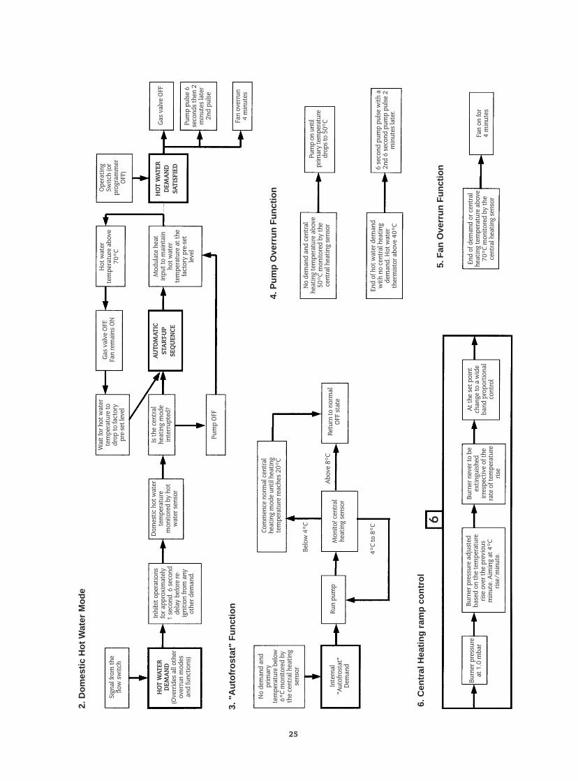
25
Sign
al fr
om th
eflo
w s
witc
h
HOT
WAT
ERDE
MA
ND
(Ove
rrid
es a
ll ot
her
over
run
mod
esan
d fu
nctio
ns)
No d
eman
d an
dpr
imar
yte
mpe
ratu
re b
elow
6°C
mon
itore
d by
the
cent
ral h
eatin
gse
nsor
Inte
rnal
"Aut
ofro
stat
"De
man
d
Run
pum
p
Belo
w 4
°C
Abov
e 8°
C
4°C
to 8
°C
Mon
itor c
entr
alhe
atin
g se
nsor
Burn
er p
ress
ure
at 1
.0 m
bar
6
Burn
er p
ress
ure
adju
sted
base
d on
the
tem
pera
ture
rise
over
the
prev
ious
min
ute.
Aim
ing
at 4
°Cris
e/m
inut
e.
Burn
er n
ever
to b
eex
tingu
ishe
dirr
espe
ctiv
e of
the
rate
of t
empe
ratu
reris
e
At th
e se
t poi
ntch
ange
to a
wid
eba
nd p
ropo
rtio
nal
cont
rol
Com
men
ce n
orm
al c
entr
alhe
atin
g m
ode
until
hea
ting
tem
pera
ture
reac
hes
20°C
Retu
rn to
nor
mal
OFF
stat
e
Pum
p on
unt
il pr
imar
y te
mpe
ratu
redr
ops t
o 50
°C
No d
eman
d an
d ce
ntra
lhe
atin
g te
mpe
ratu
re a
bove
50°C
mon
itore
d by
the
cent
ral h
eatin
g se
nsor
End
of h
ot w
ater
dem
and
with
no
cent
ral h
eatin
gde
man
d. H
ot w
ater
ther
mis
tor a
bove
40°
C
6 se
cond
pum
p pu
lse
with
a2n
d 6
seco
nd p
ump
puls
e 2
min
utes
late
r.
End
of d
eman
d or
cen
tral
heat
ing
tem
pera
ture
abo
ve70
°C m
onito
red
by th
ece
ntra
l hea
ting
sens
or
Fan
on fo
r4
min
utes
Inhi
bit o
pera
tions
for a
ppro
xim
atel
y1
seco
nd. 6
sec
ond
dela
y be
fore
re-
igni
tion
from
any
othe
r dem
and.
Is th
e ce
ntra
lhe
atin
g m
ode
inte
rrup
ted?
AUTO
MAT
ICST
ART
-UP
SEQ
UEN
CE
HOT
WAT
ERDE
MA
ND
SATI
SFIE
D
Pum
p OF
F
Wai
t for
hot
wat
erte
mpe
ratu
re to
drop
to fa
ctor
ypr
e-se
t lev
el
Gas
valv
e OF
F.Fa
n re
mai
ns O
NH
ot w
ater
tem
pera
ture
abo
ve70
°C
Mod
ulat
e he
atin
put t
o m
aint
ain
hot w
ater
tem
pera
ture
at t
hefa
ctor
y pr
e-se
t le
vel
Gas
valv
e OF
F
Fan
over
run
4 m
inut
es
Oper
atin
gSw
itch
(or
prog
ram
mer
OFF)
Dom
estic
hot
wat
erte
mpe
ratu
rem
onito
red
by h
otw
ater
sen
sor
3. "
Aut
ofro
stat
" F
unct
ion
4. P
ump
Ove
rrun
Fun
ctio
n
5. F
an O
verr
un F
unct
ion
2. D
omes
tic H
ot W
ater
Mod
e
6. C
entr
al H
eatin
g ra
mp
cont
rol
Pum
p pu
lse
6se
cond
s th
en 2
min
utes
late
r2n
d pu
lse
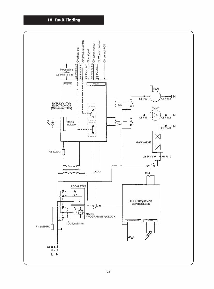
26
F1 2ATHRC
F2 1.25AT
Optional linksSparkFlame sense
Outputs Inputs
Mainsindicator
Modulatingvalve
Ove
rhea
t sta
tX
6P
ins
8 &
9X6 Pins 15 & 16
X6
Pin
s 5,
6 &
7
X6
Pin
s 1
& 2
X6
Pin
s 19
& 2
0
X6
Pin
s 3
& 4
Flo
w s
igna
l
CH
tem
p. s
enso
r
DH
W te
mp.
sen
sor
CH
con
trol
PO
T
Air
pres
sure
sw
itch
MAINSPROGRAMMER/CLOCK
FULL SEQUENCECONTROLLER
GAS VALVE
LOW VOLTAGEELECTRONICS
(Microcontroller)
ROOM STAT
X1
X2
3 2 1
1
2
3
4
6
5
RL1
X3 Pin 1 X3 Pin 2
X4 Pin 3
X5 Pin 3
X5 Pin 2X5 Pin 1
X4 Pin 1
FAN
PUMP
RL3
RL4
N
N
N
NL
18. Fault Finding
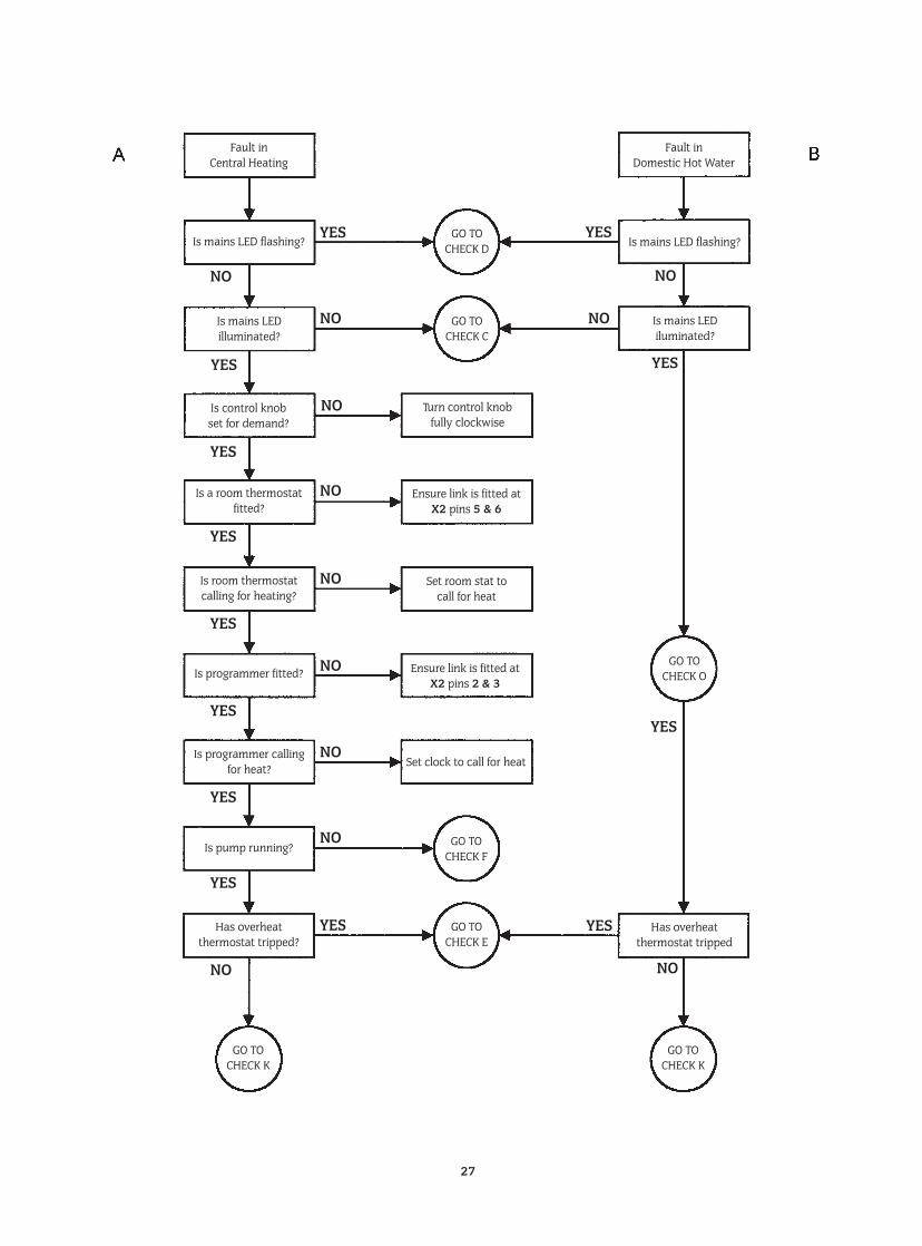
27
Fault inCentral Heating
Fault inDomestic Hot Water
Is mains LED flashing?
Is mains LEDiluminated?
Turn control knobfully clockwise
Set room stat to call for heat
Ensure link is fitted atX2 pins 2 & 3
Set clock to call for heat
Has overheat thermostat tripped
Ensure link is fitted atX2 pins 5 & 6
Is mains LED flashing?GO TO
CHECK D
GO TOCHECK K
GO TOCHECK K
GO TOCHECK E
GO TOCHECK F
GO TOCHECK O
GO TOCHECK C
Is control knob set for demand?
Is a room thermostatfitted?
Is room thermostatcalling for heating?
Is programmer fitted?
Is programmer callingfor heat?
Is pump running?
Has overheat thermostat tripped?
Is mains LED illuminated?
YES YES
YES
YES
YES
YES
NO
YES
YES
YES
YES
YES
YES YES
NO NO
NO
NO
NO
NO
NO
NO
NO
NO
NO
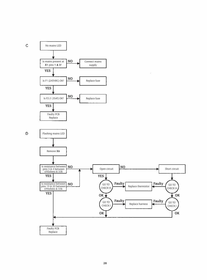
28
No mains LED
Connect mainssupply
Replace fuseIs F1 (2ATHRC) OK?
Is F2 (1.25AT) OK?
Faulty PCBReplace
Flashing mains LED
Remove X6
Open circuit
Replace thermistor
Replace harness
Short circuit
Faulty PCBReplace
Is resistance betweenpins 3 & 4 between
690ohms & 33k
Is resistance betweenpins 19 & 20 between
690ohms & 33k
Replace fuse
Is mains present atX1 pins 1 & 3?
GO TOCHECK H
GO TOCHECK I
GO TOCHECK H
GO TOCHECK J
NO
NO
NO
YES
YES
YES
YES
YES
YES
NO NO
OK
OK
OK
OK
Faulty
Faulty
Faulty
Faulty
NO
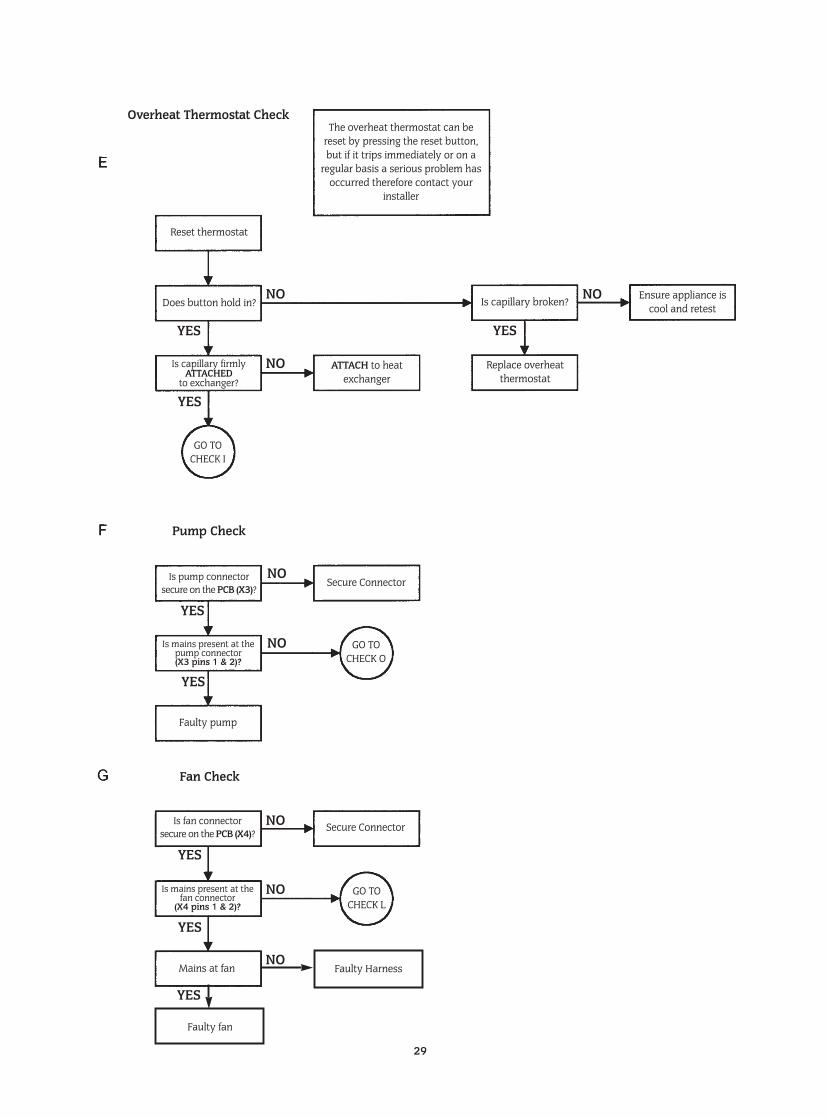
29
The overheat thermostat can bereset by pressing the reset button,but if it trips immediately or on a
regular basis a serious problem hasoccurred therefore contact your
installer
Reset thermostat
Overheat Thermostat Check
Pump Check
Fan Check
Does button hold in?
Secure Connector
Secure Connector
Faulty pump
Is pump connectorsecure on the PCB (X3)?
Is fan connectorsecure on the PCB (X4)?
Is mains present at thepump connector(X3 pins 1 & 2)?
Is mains present at thefan connector
(X4 pins 1 & 2)?
ATTACH to heatexchanger
Is capillary broken? Ensure appliance iscool and retest
Replace overheatthermostat
Is capillary firmlyATTACHED
to exchanger?
GO TOCHECK I
GO TOCHECK O
GO TOCHECK L
YES
YES
YES
YES
YES
YES
NO
NO
NO
NO
YES
NONO
NO
Faulty Harness
Faulty fan
YES
Mains at fanNO
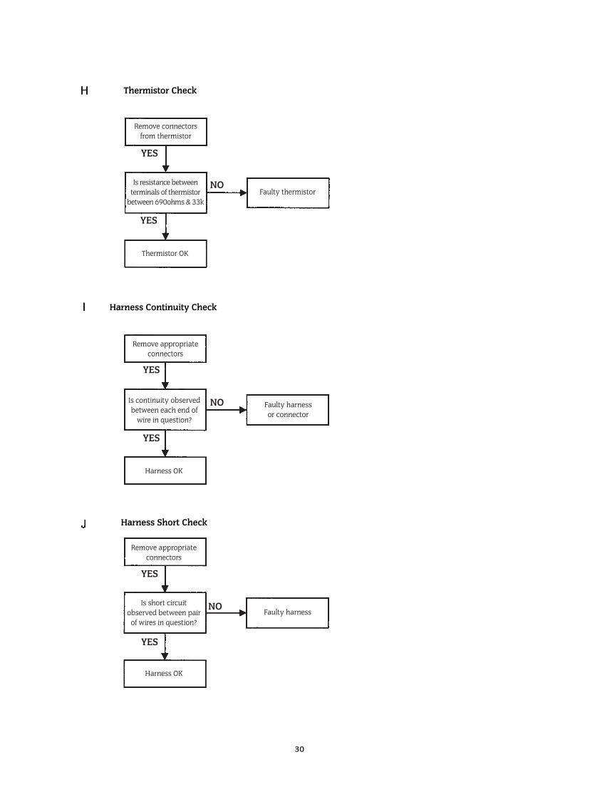
30
Thermistor Check
Harness Continuity Check
Harness Short Check
Remove connectorsfrom thermistor
Thermistor OK
Remove appropriateconnectors
Is continuity observedbetween each end of
wire in question?
Faulty harness or connector
Harness OK
Remove appropriateconnectors
Faulty harness
Harness OK
Is short circuit observed between pair
of wires in question?
Is resistance betweenterminals of thermistor
between 690ohms & 33kFaulty thermistor
YES
YES
YES
YES
NO
NO
YES
YES
NO
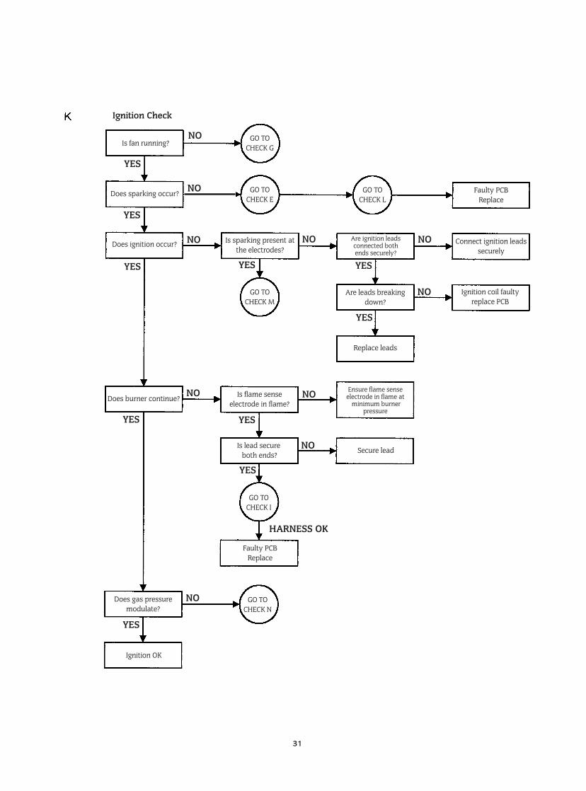
31
Ignition Check
Is fan running?
Is sparking present atthe electrodes?
Faulty PCBReplace
Connect ignition leadssecurely
Are leads breakingdown?
Ignition coil faultyreplace PCB
Replace leads
Does burner continue?
Does gas pressure modulate?
Ignition OK
Faulty PCB Replace
Is flame senseelectrode in flame?
Is lead secureboth ends? Secure lead
Ensure flame senseelectrode in flame at
minimum burnerpressure
Are ignition leads connected both ends securely?
Does sparking occur?
Does ignition occur?
YES
YES
YES
YES
YES
HARNESS OK
YES
YES
YES
YES
YES
NO
NO
NO
NO
NO
NO NO
NO
NO
NO
GO TOCHECK G
GO TOCHECK E
GO TOCHECK M
GO TOCHECK I
GO TOCHECK N
GO TOCHECK L
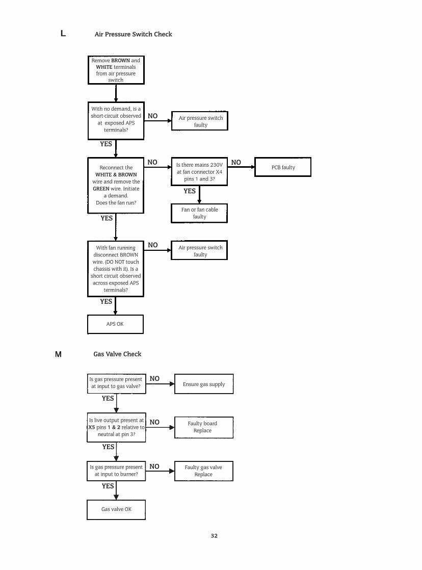
32
Remove BROWN andWHITE terminalsfrom air pressure
switch
Air pressure switchfaulty
With no demand, is ashort-circuit observed
at exposed APS terminals?
Reconnect the WHITE & BROWN
wire and remove theGREEN wire. Initiate
a demand.Does the fan run?
PCB faulty
Air pressure switchfaulty
APS OK
Is gas pressure presentat input to gas valve? Ensure gas supply
Faulty boardReplace
Faulty gas valveReplace
Is live output present atX5 pins 1 & 2 relative to
neutral at pin 3?
Is gas pressure presentat input to burner?
Gas valve OK
With fan running disconnect BROWNwire. (DO NOT touchchassis with it). Is a
short circuit observedacross exposed APS
terminals?
Gas Valve Check
NO
NO
NO
YES
YES
YES
YES
YES
NO
NO
NO
Air Pressure Switch Check
Is there mains 230Vat fan connector X4
pins 1 and 3?
YES
Fan or fan cable faulty
NO
YES
L
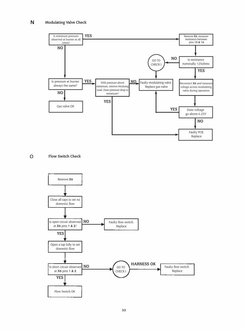
With pressure above minimum, remove ModuregLead. Does pressure drop to
minimum?
33
Is minimum pressureobserved at burner at all
times?
Modulating Valve Check
Flow Switch Check
GO TOCHECK I
YES
YES
GO TOCHECK I
YES
YES
NO
NO HARNESS OK
YES
YES
NO
NO
NO
NO
Is pressure at burneralways the same?
Is resistance nominally 125ohms
Does voltagego above 6.25V
Faulty PCB.Replace
Reconnect X6 and measurevoltage across modulating
valve during operation
Gas valve OK
Remove X6
Close all taps to set nodomestic flow
Faulty flow switch.Replace
Faulty flow switch.Replace
Is short circuit observedat X6 pins 1 & 2
Is open circuit observedat X6 pins 1 & 2?
Open a tap fully to setdomestic flow
Flow Switch OK
Faulty modulating valve .Replace gas valve
Remove X6, measure resistance between
pins 15 & 16
N
YES
NO
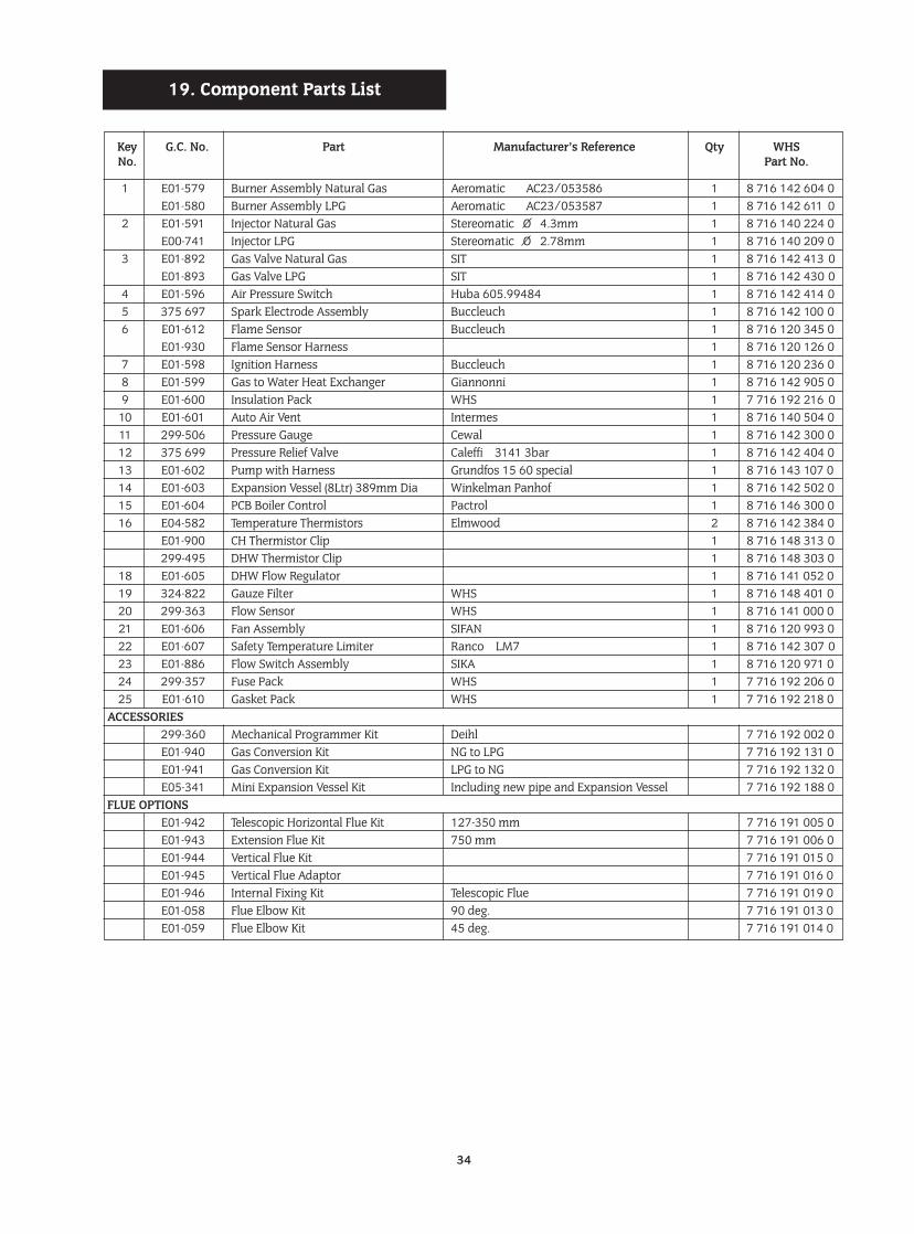
34
Key G.C. No. Part Manufacturer’s Reference Qty WHSNo. Part No.
1 E01-579 Burner Assembly Natural Gas Aeromatic AC23/053586 1 8 716 142 604 0E01-580 Burner Assembly LPG Aeromatic AC23/053587 1 8 716 142 611 0
2 E01-591 Injector Natural Gas Stereomatic O 4.3mm 1 8 716 140 224 0E00-741 Injector LPG Stereomatic O 2.78mm 1 8 716 140 209 0
3 E01-892 Gas Valve Natural Gas SIT 1 8 716 142 413 0E01-893 Gas Valve LPG SIT 1 8 716 142 430 0
4 E01-596 Air Pressure Switch Huba 605.99484 1 8 716 142 414 05 375 697 Spark Electrode Assembly Buccleuch 1 8 716 142 100 06 E01-612 Flame Sensor Buccleuch 1 8 716 120 345 0
E01-930 Flame Sensor Harness 1 8 716 120 126 07 E01-598 Ignition Harness Buccleuch 1 8 716 120 236 08 E01-599 Gas to Water Heat Exchanger Giannonni 1 8 716 142 905 09 E01-600 Insulation Pack WHS 1 7 716 192 216 0
10 E01-601 Auto Air Vent Intermes 1 8 716 140 504 011 299-506 Pressure Gauge Cewal 1 8 716 142 300 012 375 699 Pressure Relief Valve Caleffi 3141 3bar 1 8 716 142 404 013 E01-602 Pump with Harness Grundfos 15 60 special 1 8 716 143 107 014 E01-603 Expansion Vessel (8Ltr) 389mm Dia Winkelman Panhof 1 8 716 142 502 015 E01-604 PCB Boiler Control Pactrol 1 8 716 146 300 016 E04-582 Temperature Thermistors Elmwood 2 8 716 142 384 0
E01-900 CH Thermistor Clip 1 8 716 148 313 0 299-495 DHW Thermistor Clip 1 8 716 148 303 0
18 E01-605 DHW Flow Regulator 1 8 716 141 052 019 324-822 Gauze Filter WHS 1 8 716 148 401 020 299-363 Flow Sensor WHS 1 8 716 141 000 021 E01-606 Fan Assembly SIFAN 1 8 716 120 993 022 E01-607 Safety Temperature Limiter Ranco LM7 1 8 716 142 307 023 E01-886 Flow Switch Assembly SIKA 1 8 716 120 971 024 299-357 Fuse Pack WHS 1 7 716 192 206 0 25 E01-610 Gasket Pack WHS 1 7 716 192 218 0
ACCESSORIES299-360 Mechanical Programmer Kit Deihl 7 716 192 002 0E01-940 Gas Conversion Kit NG to LPG 7 716 192 131 0E01-941 Gas Conversion Kit LPG to NG 7 716 192 132 0E05-341 Mini Expansion Vessel Kit Including new pipe and Expansion Vessel 7 716 192 188 0
FLUE OPTIONSE01-942 Telescopic Horizontal Flue Kit 127-350 mm 7 716 191 005 0E01-943 Extension Flue Kit 750 mm 7 716 191 006 0E01-944 Vertical Flue Kit 7 716 191 015 0E01-945 Vertical Flue Adaptor 7 716 191 016 0E01-946 Internal Fixing Kit Telescopic Flue 7 716 191 019 0E01-058 Flue Elbow Kit 90 deg. 7 716 191 013 0E01-059 Flue Elbow Kit 45 deg. 7 716 191 014 0
19. Component Parts List
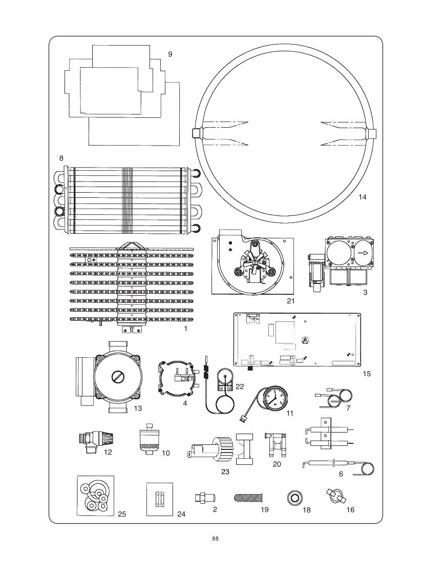
35
9
8
14
321
1
15
134
22
117
12 10
23 206
25 242 19 18 16
23

This booklet is accurate at the date of printing but will be superseded and should be disregarded if specifications and/or appearances are changed in the interestsof continued improvement.
All goods sold are subject to our official Conditions of Sale, a copy of which may be obtained on application.PUBLICATION 8 716 145 028C 11/98
Bosch GroupWorcester Heat Systems Limited, Cotswold Way, Warndon, Worcester WR4 9SW.
Telephone: (01905) 754624. Fax: (01905) 754619.Technical Helpline (0990) 266241.