BOS 08M Photoelectric Connection Sensors Accessoriesballuff-ua.com/pdf/optic_cyl_en.pdf · 2.1.2...
94
2.1.2 BOS 08M Connection Accessories The new dimension from Balluff – small in size, big in performance Miniaturization in the Balluff line continues at full pace. The new Opto-mini.s BOS 08M sensors stand out with ease of handling and fixed sensing distances and ranges. This sensor family includes diffuse sensors in tubular M8 housing, retroreflective and through-beam sensors. These small photoelectric sensors open up possibilities in high-dynamic applications such as on robot gripper arms. Here is where components with the lightest weight, a small footprint and yet the greatest switching precision are demanded. In short: The new BOS 08M are small, tough, flexible and economical. Diffuse, Retroreflective, Through-beam Receiver Wiring diagrams Through-beam emitter Recommended accessories please order separately Connector BKS-_ 48/BKS-_ 49 Reflector BOS R-9 Photoelectric Sensors
Transcript of BOS 08M Photoelectric Connection Sensors Accessoriesballuff-ua.com/pdf/optic_cyl_en.pdf · 2.1.2...
2.1.2
BOS 08MConnectionAccessories
The new dimension fromBalluff – small in size,big in performance
Miniaturization in the Balluffline continues at full pace.The new Opto-mini.sBOS 08M sensors stand outwith ease of handling andfixed sensing distances andranges.
This sensor family includesdiffuse sensors in tubularM8 housing, retroreflectiveand through-beam sensors.
These small photoelectricsensors open up possibilitiesin high-dynamic applicationssuch as on robot gripperarms. Here is wherecomponents with the lightestweight, a small footprint andyet the greatest switchingprecision are demanded.
In short: The new BOS 08Mare small, tough, flexible andeconomical.
Diffuse, Retroreflective,Through-beam Receiver
Wiring diagrams
Through-beam emitter
Recommendedaccessoriesplease order separately
ConnectorBKS-_ 48/BKS-_ 49
ReflectorBOS R-9
PhotoelectricSensors
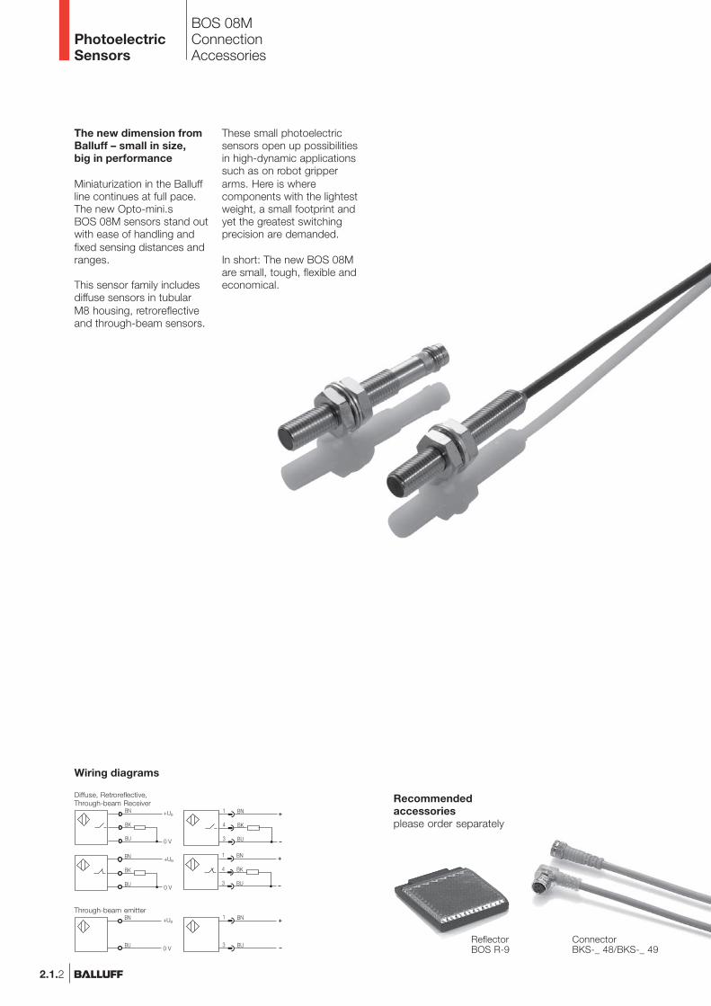
BOS 08MProduct Overview
2.1.3
Photoelectricsensorsaccessoriespage 2.3.2 ...
2.1
2.3
Type
DiffuseBOS 08M-PS-RD11-S49BOS 08M-PO-RD11-S49BOS 08M-PS-RD11-02BOS 08M-PO-RD11-02
RetroreflectiveBOS 08M-PS-PR11-S49BOS 08M-PO-PR11-S49BOS 08M-PS-PR11-02BOS 08M-PO-PR11-02
Through-beamBOS 08M-PS-RE10-S49BOS 08M-PO-RE10-S49BOS 08M-PS-RE10-03BOS 08M-PO-RE10-03
BOS 08M-X-RS10-S49BOS 08M-X-RS10-03
OutputLighttype
Sensingdistance/range
0...55 mm0...55 mm 0...55 mm0...55 mm
25...550 mm25...550 mm25...550 mm25...550 mm
0...1.1 m0...1.1 m0...1.1 m0...1.1 m
0...1.1 m0...1.1 m
Connec-tion
500 Hz500 Hz500 Hz500 Hz
500 Hz500 Hz500 Hz500 Hz
500 Hz500 Hz500 Hz500 Hz
Outputfunction
Page
2.1.42.1.42.1.42.1.4
2.1.42.1.42.1.52.1.5
2.1.52.1.52.1.52.1.5
2.1.52.1.5
Specialfeatures
Red
ligh
t
Infra
red
M8
conn
ecto
r, 3-
pin
Cab
le
10...
30 V
DC
Pol
ariz
ing
filte
r
NP
N-T
rans
isto
r
PN
P-T
rans
isto
r
Ligh
t-on
Dar
k-on
UBSwitchingfrequency
mini.sM8 Metal
www.balluff.com
Connectors ...page 5.2 ...
5
PhotoelectricSensors
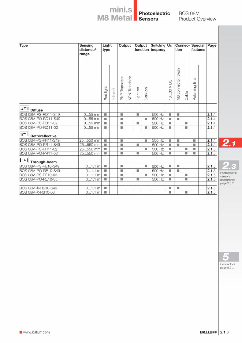
BOS 08MSensing distance 55 mmRange 550 mm
2.1.4
25...550 mm
BOS 08M-PS-PR11-S49BOS 08M-PO-PR11-S49
10...30 V DC10 %20 mA
PNP-Transistor100 mA
Light- or dark-on≤ 2 Vfixed
25...550 mmLED, red light
640 nm
LED yellow
1 ms500 Hz
M8×57.5 mmM8 connector, 3-pin
Nickel plated brassPMMA13 g
IP 67yesyes
–10...+60 °CEN 60947-5-2
0...55 mm
BOS 08M-PS-RD11-02BOS 08M-PO-RD11-02
10...30 V DC10 %20 mA
PNP-Transistor100 mA
Light- or dark-on≤ 2 Vfixed
0...50 mmLED, red light
640 nm
LED yellow
1 ms500 Hz
M8×50 mm2 m cable, PUR
3×0.14 mm²Nickel plated brass
PMMA47 g
IP 67yesyes
–10...+60 °CEN 60947-5-2
0...55 mm
BOS 08M-PS-RD11-S49BOS 08M-PO-RD11-S49
10...30 V DC10 %20 mA
PNP-Transistor100 mA
Light- or dark-on≤ 2 Vfixed
0...50 mmLED, red light
640 nm
LED yellow
1 ms500 Hz
M8×57.5 mmM8 connector, 3-pin
Nickel plated brassPMMA13 g
IP 67yesyes
–10...+60 °CEN 60947-5-2
Diffuse Sensing distanceRetroreflective RangeThrough-beam Range
DiffusePNP, NO 55 mmPNP, NC 55 mmRetroreflectivePNP, NO 550 mm polarizing filterPNP, NC 550 mm polarizing filterThrough-beamPNP, NO 1.1 m ReceiverPNP, NC 1.1 m Receiver
1.1 m EmitterElectrical dataSupply voltage UB
RippleNo-load supply current I0 max.Switching outputOutput currentSwitching typeVoltage drop Ud at IeSettingsOptical dataRecommended sensing distance/rangeEmitter, light typeWavelengthIndicatorsLight reception indicatorOutput function indicatorTime dataResponse timeSwitching frequency fMechanical dataDimensionsConnectionNo. of wires × cross-sectionHousing materialOptical surfaceWeightAmbient dataDegree of protection per IEC 60529Polarity reversal protectedShort circuit protectedAmbient temperature range Ta
Ambient light rejection per
Diffuse values referenced to Kodak gray card 90% Reflexion.Retroreflective values referenced to R9 reflector.
PhotoelectricSensors
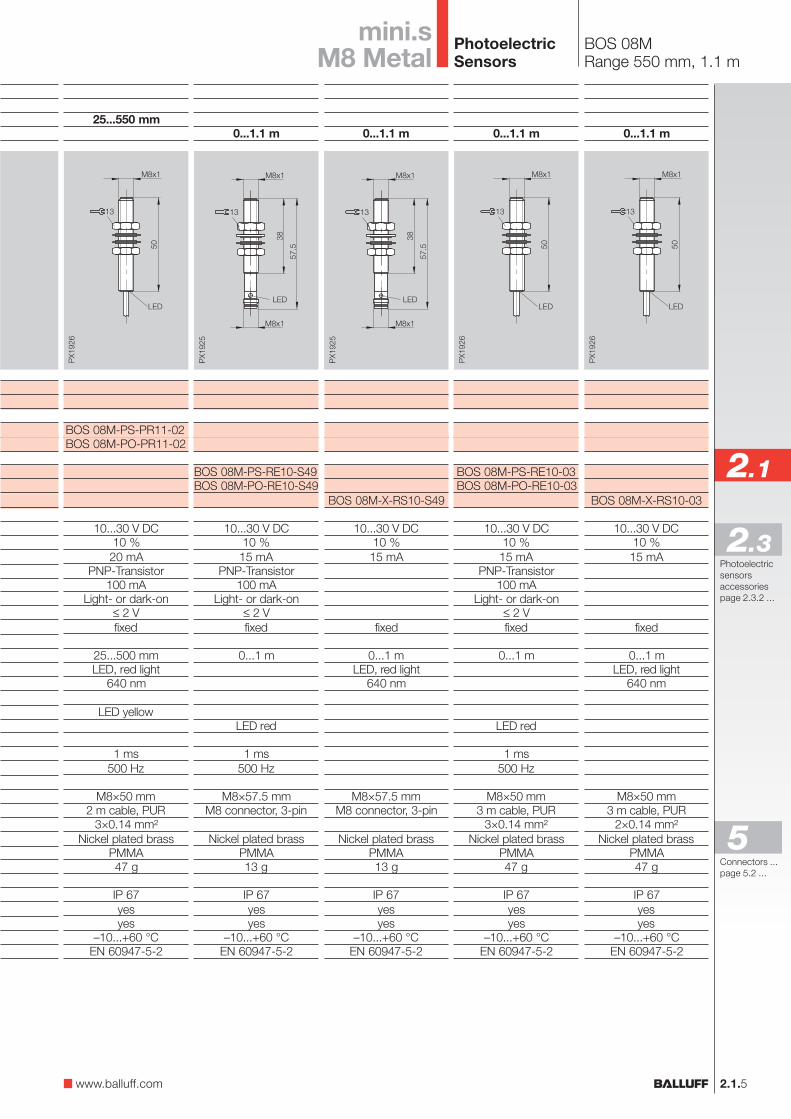
BOS 08MRange 550 mm, 1.1 m
2.1.5
0...1.1 m
BOS 08M-PS-RE10-03BOS 08M-PO-RE10-03
10...30 V DC10 %15 mA
PNP-Transistor100 mA
Light- or dark-on≤ 2 Vfixed
0...1 m
LED red
1 ms500 Hz
M8×50 mm3 m cable, PUR
3×0.14 mm²Nickel plated brass
PMMA47 g
IP 67yesyes
–10...+60 °CEN 60947-5-2
0...1.1 m
BOS 08M-X-RS10-03
10...30 V DC10 %15 mA
fixed
0...1 mLED, red light
640 nm
M8×50 mm3 m cable, PUR
2×0.14 mm²Nickel plated brass
PMMA47 g
IP 67yesyes
–10...+60 °CEN 60947-5-2
0...1.1 m
BOS 08M-PS-RE10-S49BOS 08M-PO-RE10-S49
10...30 V DC10 %15 mA
PNP-Transistor100 mA
Light- or dark-on≤ 2 Vfixed
0...1 m
LED red
1 ms500 Hz
M8×57.5 mmM8 connector, 3-pin
Nickel plated brassPMMA13 g
IP 67yesyes
–10...+60 °CEN 60947-5-2
0...1.1 m
BOS 08M-X-RS10-S49
10...30 V DC10 %15 mA
fixed
0...1 mLED, red light
640 nm
M8×57.5 mmM8 connector, 3-pin
Nickel plated brassPMMA13 g
IP 67yesyes
–10...+60 °CEN 60947-5-2
25...550 mm
BOS 08M-PS-PR11-02BOS 08M-PO-PR11-02
10...30 V DC10 %20 mA
PNP-Transistor100 mA
Light- or dark-on≤ 2 Vfixed
25...500 mmLED, red light
640 nm
LED yellow
1 ms500 Hz
M8×50 mm2 m cable, PUR
3×0.14 mm²Nickel plated brass
PMMA47 g
IP 67yesyes
–10...+60 °CEN 60947-5-2
Photoelectricsensorsaccessoriespage 2.3.2 ...
2.1
2.3
mini.sM8 Metal
www.balluff.com
Connectors ...page 5.2 ...
5
PhotoelectricSensors

Features
– Supply voltage10...30 V DC,polarity reversal protected
– Function indicatorfor the output
– Degree of protection IP 67– Standard (M12×1)
metal housing– Red and infrared light
versions– Fixed and adjustable
sensitivity– PNP or NPN,
light switching ordark switching
– Cable and connectorversions (M12 connector)
One feature stands out inall these ingenious designs:Simplicity.
Series BOS 12M representsa radical simplification ofsensor technology for themost common applications.
All the sensors are enclosedin the same housing as atypical inductive proximityswitch (M12×1). This meansphotoelectric sensorsand inductive proximityswitches are mechanicallyand electricallycompatible!As for mounting, there is nosimpler concept for sensorsthan a bore hole.
This brings simplification tothe design of the system ormachine, makes conversionsof the sensing principleeasier while using multi-useof the accessories toreduce inventory. Thatmeans standardizationand simplification of thesensors. Series BOS 12Min the tough metal housingis fully potted, with anenclosure rating of IP 67.
There is a new laser through-beam model available in2 versions. For long range orsmall parts detection.
BOS 12M
Applications
– General automation tasks– Assembly and handling– Machine tools– Packaging– Robots– Machine tool building
2.1.6
PhotoelectricSensors
BOS 12MProduct Overview
2.1.7
Photoelectricsensorsaccessoriespage 2.3.2 ...
2.1
2.3
Type
Diffusewith HGA
BOS 12M-PS-1N1I-S4-CBOS 12M-PU-1HA-S4-C
DiffuseBOS 12M-PS-1YA-S4-CBOS 12M-PO-1YA-S4-CBOS 12M-PS-1YA-B0-C-03BOS 12M-PO-1YA-B0-C-03
BOS 12M-PS-1YB-S4-CBOS 12M-PO-1YB-S4-CBOS 12M-PS-1YB-B0-C-03BOS 12M-PO-1YB-B0-C-03
BOS 12M-PS-1PD-S4-CBOS 12M-PO-1PD-S4-CBOS 12M-PS-1PD-B0-C-03BOS 12M-PO-1PD-B0-C-03
Retro-reflectiveBOS 12M-PS-1QA-S4-CBOS 12M-PO-1QA-S4-CBOS 12M-PS-1QA-B0-C-03BOS 12M-PO-1QA-B0-C-03
Through-beamBLE 12M-PA-1PD-S4-CBLE 12M-PA-1PD-B0-C-03
BLS 12M-XX-1RD-S4-LBLS 12M-XX-1RD-B0-L-03
LaserThrough-beam
BOS 12M-PA-LE10-S4BOS 12M-PA-LE10-03BOS 12M-NA-LE10-S4BOS 12M-NA-LE10-03
BOS 12M-XT-LS11-S4BOS 12M-XT-LS11-03BOS 12M-XT-LS12-S4BOS 12M-XT-LS12-03
OutputLighttype
Sensingdistance/range
0...24 mm10...60 mm
1...100 mm1...100 mm1...100 mm1...100 mm
1...200 mm1...200 mm1...200 mm1...200 mm
1...400 mm1...400 mm1...400 mm1...400 mm
0...1,5 m0...1,5 m0...1,5 m0...1,5 m
0...5 m0...5 m
0...5 m0...5 m
0...3 m0...3 m
0...30 m0...30 m
Connec-tion
1 kHz1 kHz
200 Hz200 Hz200 Hz200 Hz
200 Hz200 Hz200 Hz200 Hz
200 Hz200 Hz200 Hz200 Hz
200 Hz200 Hz200 Hz200 Hz
500 Hz500 Hz
1 kHz1 kHz1 kHz1 kHz
Outputfunction
Page
2.1.82.1.8
2.1.82.1.82.1.92.1.9
2.1.92.1.92.1.92.1.9
2.1.92.1.92.1.92.1.9
2.1.102.1.102.1.102.1.10
2.1.112.1.11
2.1.112.1.11
2.1.132.1.132.1.132.1.13
2.1.152.1.152.1.152.1.15
Features
Red
ligh
t
Infra
red
M12
con
nect
or, 4
-pin
Cab
le, 3
m
10...
30 V
DC
Pol
ariz
ing
filte
r
NP
N-T
rans
isto
r
PN
P-T
rans
isto
r
Ligh
t-on
Dar
k-on
Teac
h-in
UBSwitchingfrequency
M12 Metal
www.balluff.com
Connectors ...page 5.2 ...
5
Lase
r
PhotoelectricSensors
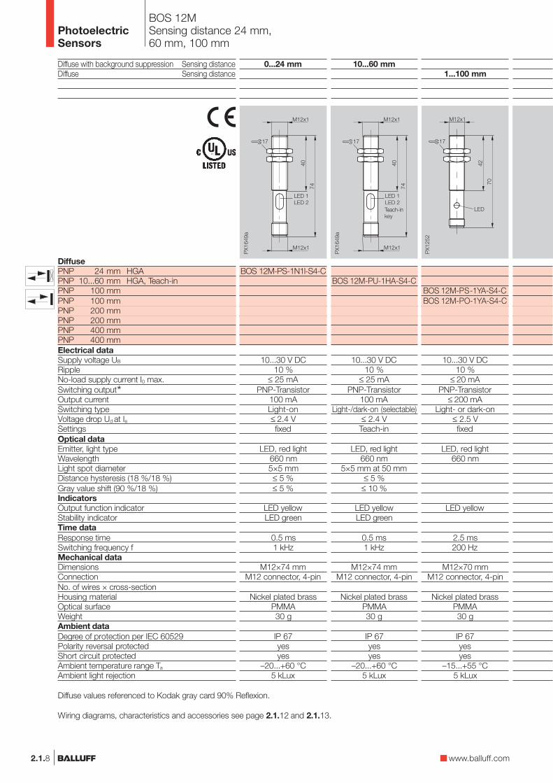
BOS 12MSensing distance 24 mm,60 mm, 100 mm
1...100 mm
BOS 12M-PS-1YA-S4-CBOS 12M-PO-1YA-S4-C
10...30 V DC10 %
≤ 20 mAPNP-Transistor
≤ 200 mALight- or dark-on
≤ 2.5 Vfixed
LED, red light660 nm
LED yellow
2.5 ms200 Hz
M12×70 mmM12 connector, 4-pin
Nickel plated brassPMMA30 g
IP 67yesyes
–15...+55 °C5 kLux
2.1.8
Diffuse with background suppression Sensing distanceDiffuse Sensing distance
DiffusePNP 24 mm HGAPNP 10...60 mm HGA, Teach-inPNP 100 mmPNP 100 mmPNP 200 mmPNP 200 mmPNP 400 mmPNP 400 mmElectrical dataSupply voltage UB
RippleNo-load supply current I0 max.Switching output*Output currentSwitching typeVoltage drop Ud at IeSettingsOptical dataEmitter, light typeWavelengthLight spot diameterDistance hysteresis (18 %/18 %)Gray value shift (90 %/18 %)IndicatorsOutput function indicatorStability indicatorTime dataResponse timeSwitching frequency fMechanical dataDimensionsConnectionNo. of wires × cross-sectionHousing materialOptical surfaceWeightAmbient dataDegree of protection per IEC 60529Polarity reversal protectedShort circuit protectedAmbient temperature range Ta
Ambient light rejection
Diffuse values referenced to Kodak gray card 90% Reflexion.
Wiring diagrams, characteristics and accessories see page 2.1.12 and 2.1.13.
10...60 mm
BOS 12M-PU-1HA-S4-C
10...30 V DC10 %
≤ 25 mAPNP-Transistor
100 mALight-/dark-on (selectable)
≤ 2.4 VTeach-in
LED, red light660 nm
5×5 mm at 50 mm≤ 5 %
≤ 10 %
LED yellowLED green
0.5 ms1 kHz
M12×74 mmM12 connector, 4-pin
Nickel plated brassPMMA30 g
IP 67yesyes
–20...+60 °C5 kLux
Teach-inkey
0...24 mm
BOS 12M-PS-1N1l-S4-C
10...30 V DC10 %
≤ 25 mAPNP-Transistor
100 mALight-on≤ 2.4 Vfixed
LED, red light660 nm5×5 mm≤ 5 %≤ 5 %
LED yellowLED green
0.5 ms1 kHz
M12×74 mmM12 connector, 4-pin
Nickel plated brassPMMA30 g
IP 67yesyes
–20...+60 °C5 kLux
www.balluff.com
PhotoelectricSensors
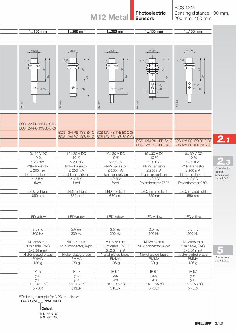
BOS 12MSensing distance 100 mm,200 mm, 400 mm
1...100 mm
BOS 12M-PS-1YA-B0-C-03BOS 12M-PO-1YA-B0-C-03
10...30 V DC10 %
≤ 20 mAPNP-Transistor
≤ 200 mALight- or dark-on
≤ 2.5 Vfixed
LED, red light660 nm
LED yellow
2.5 ms200 Hz
M12×65 mm3 m cable, PVC
3×0.34 mm²Nickel plated brass
PMMA136 g
IP 67yesyes
–15...+55 °C5 kLux
2.1.9
Photoelectricsensorsaccessoriespage 2.3.2 ...
2.1
2.3
1...200 mm
BOS 12M-PS-1YB-S4-CBOS 12M-PO-1YB-S4-C
10...30 V DC10 %
≤ 20 mAPNP-Transistor
≤ 200 mALight- or dark-on
≤ 2.5 Vfixed
LED, red light660 nm
LED yellow
2.5 ms200 Hz
M12×70 mmM12 connector, 4-pin
Nickel plated brassPMMA30 g
IP 67yesyes
–15...+55 °C5 kLux
1...400 mm
BOS 12M-PS-1PD-S4-CBOS 12M-PO-1PD-S4-C
10...30 V DC10 %
≤ 20 mAPNP-Transistor
≤ 200 mALight- or dark-on
≤ 2.5 VPotentiometer 270°
LED, infrared light880 nm
LED yellow
2.5 ms200 Hz
M12×70 mmM12 connector, 4-pin
Nickel plated brassPMMA30 g
IP 67yesyes
–15...+55 °C5 kLux
1...400 mm
BOS 12M-PS-1PD-B0-C-03BOS 12M-PO-1PD-B0-C-03
10...30 V DC10 %
≤ 20 mAPNP-Transistor
≤ 200 mALight- or dark-on
≤ 2.5 VPotentiometer 270°
LED, infrared light880 nm
LED yellow
2.5 ms200 Hz
M12×65 mm3 m cable, PVC
3×0.34 mm²Nickel plated brass
PMMA136 g
IP 67yesyes
–15...+55 °C5 kLux
PX1
288
42
70
M12x1
17
10.5 LEDns
1...200 mm
BOS 12M-PS-1YB-B0-C-03BOS 12M-PO-1YB-B0-C-03
10...30 V DC10 %
≤ 20 mAPNP-Transistor
≤ 200 mALight- or dark-on
≤ 2.5 Vfixed
LED, red light660 nm
LED yellow
2.5 ms200 Hz
M12×65 mm3 m cable, PVC
3×0.34 mm²Nickel plated brass
PMMA136 g
IP 67yesyes
–15...+55 °C5 kLux
NS NPN NONO NPN NC
BOS 12M-_ _ -1YA-S4-C
Output
*Ordering example for NPN transistor:
M12 Metal
Connectors ...page 5.2 ...
5
PhotoelectricSensors
0...1.5 m
BOS 12M-PS-1QA-B0-C-03BOS 12M-PO-1QA-B0-C-03
10...30 V DC10 %
≤ 20 mAPNP-Transistor
≤ 200 mALight- or dark-on
≤ 2.5 VPotentiometer 270°
LED, red light660 nm
LED yellow
2.5 ms200 Hz
M12×65 mm3 m cable, PVC
3×0.34 mm²Nickel plated brass
PMMA136 g
IP 67yesyes
–15...+55 °C5 kLux
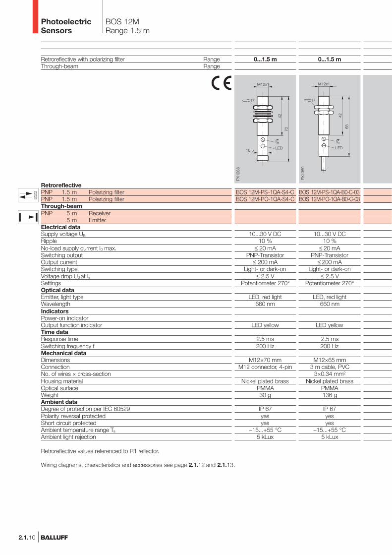
BOS 12MRange 1.5 m
0...1.5 m
BOS 12M-PS-1QA-S4-CBOS 12M-PO-1QA-S4-C
10...30 V DC10 %
≤ 20 mAPNP-Transistor
≤ 200 mALight- or dark-on
≤ 2.5 VPotentiometer 270°
LED, red light660 nm
LED yellow
2.5 ms200 Hz
M12×70 mmM12 connector, 4-pin
Nickel plated brassPMMA30 g
IP 67yesyes
–15...+55 °C5 kLux
PX1
288
42
70
M12x1
17
10.5 LEDns
2.1.10
Retroreflective with polarizing filter RangeThrough-beam Range
RetroreflectivePNP 1.5 m Polarizing filterPNP 1.5 m Polarizing filterThrough-beamPNP 5 m Receiver
5 m EmitterElectrical dataSupply voltage UB
RippleNo-load supply current I0 max.Switching outputOutput currentSwitching typeVoltage drop Ud at IeSettingsOptical dataEmitter, light typeWavelengthIndicatorsPower-on indicatorOutput function indicatorTime dataResponse timeSwitching frequency fMechanical dataDimensionsConnectionNo. of wires × cross-sectionHousing materialOptical surfaceWeightAmbient dataDegree of protection per IEC 60529Polarity reversal protectedShort circuit protectedAmbient temperature range Ta
Ambient light rejection
Retroreflective values referenced to R1 reflector.
Wiring diagrams, characteristics and accessories see page 2.1.12 and 2.1.13.
PhotoelectricSensors
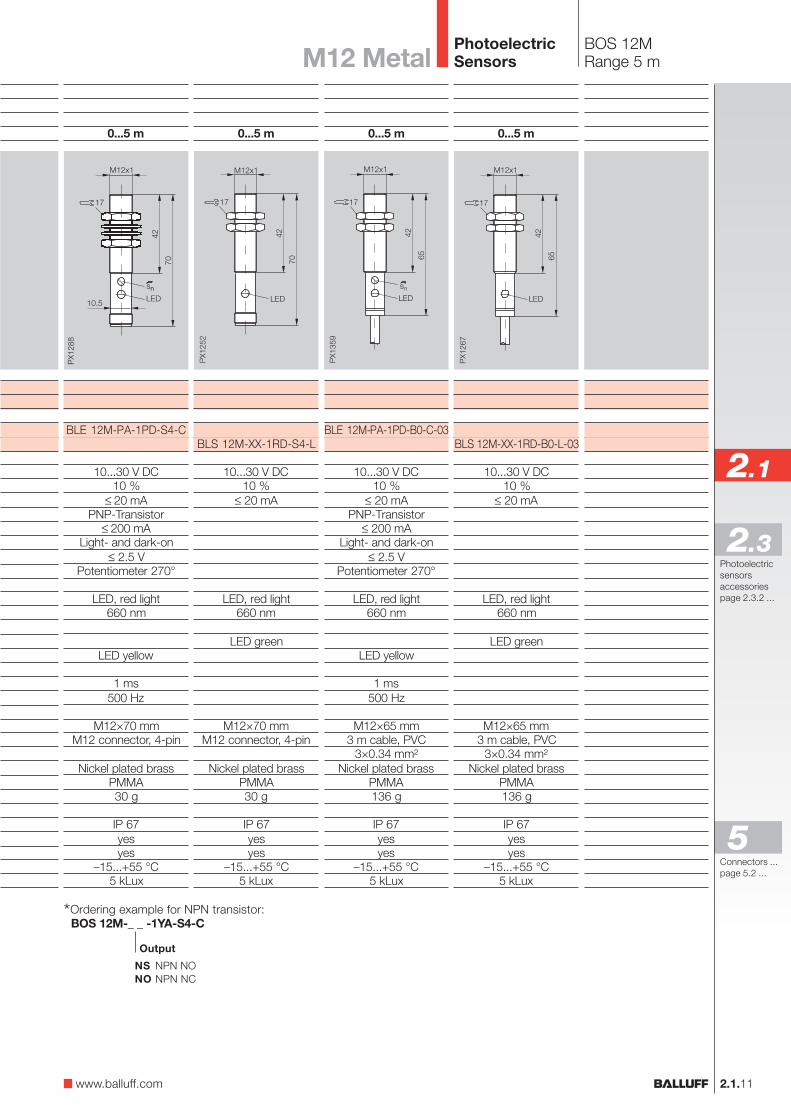
BOS 12MRange 5 m
2.1.11
Photoelectricsensorsaccessoriespage 2.3.2 ...
2.1
2.3
0...5 m
BLE 12M-PA-1PD-S4-C
10...30 V DC10 %
≤ 20 mAPNP-Transistor
≤ 200 mALight- and dark-on
≤ 2.5 VPotentiometer 270°
LED, red light660 nm
LED yellow
1 ms500 Hz
M12×70 mmM12 connector, 4-pin
Nickel plated brassPMMA30 g
IP 67yesyes
–15...+55 °C5 kLux
PX1
288
42
70M12x1
17
10.5 LEDns
0...5 m
BLS 12M-XX-1RD-B0-L-03
10...30 V DC10 %
≤ 20 mA
LED, red light660 nm
LED green
M12×65 mm3 m cable, PVC
3×0.34 mm²Nickel plated brass
PMMA136 g
IP 67yesyes
–15...+55 °C5 kLux
0...5 m
BLE 12M-PA-1PD-B0-C-03
10...30 V DC10 %
≤ 20 mAPNP-Transistor
≤ 200 mALight- and dark-on
≤ 2.5 VPotentiometer 270°
LED, red light660 nm
LED yellow
1 ms500 Hz
M12×65 mm3 m cable, PVC
3×0.34 mm²Nickel plated brass
PMMA136 g
IP 67yesyes
–15...+55 °C5 kLux
0...5 m
BLS 12M-XX-1RD-S4-L
10...30 V DC10 %
≤ 20 mA
LED, red light660 nm
LED green
M12×70 mmM12 connector, 4-pin
Nickel plated brassPMMA30 g
IP 67yesyes
–15...+55 °C5 kLux
NS NPN NONO NPN NC
BOS 12M-_ _ -1YA-S4-C
Output
*Ordering example for NPN transistor:
M12 Metal
www.balluff.com
Connectors ...page 5.2 ...
5
PhotoelectricSensors
2.1.12
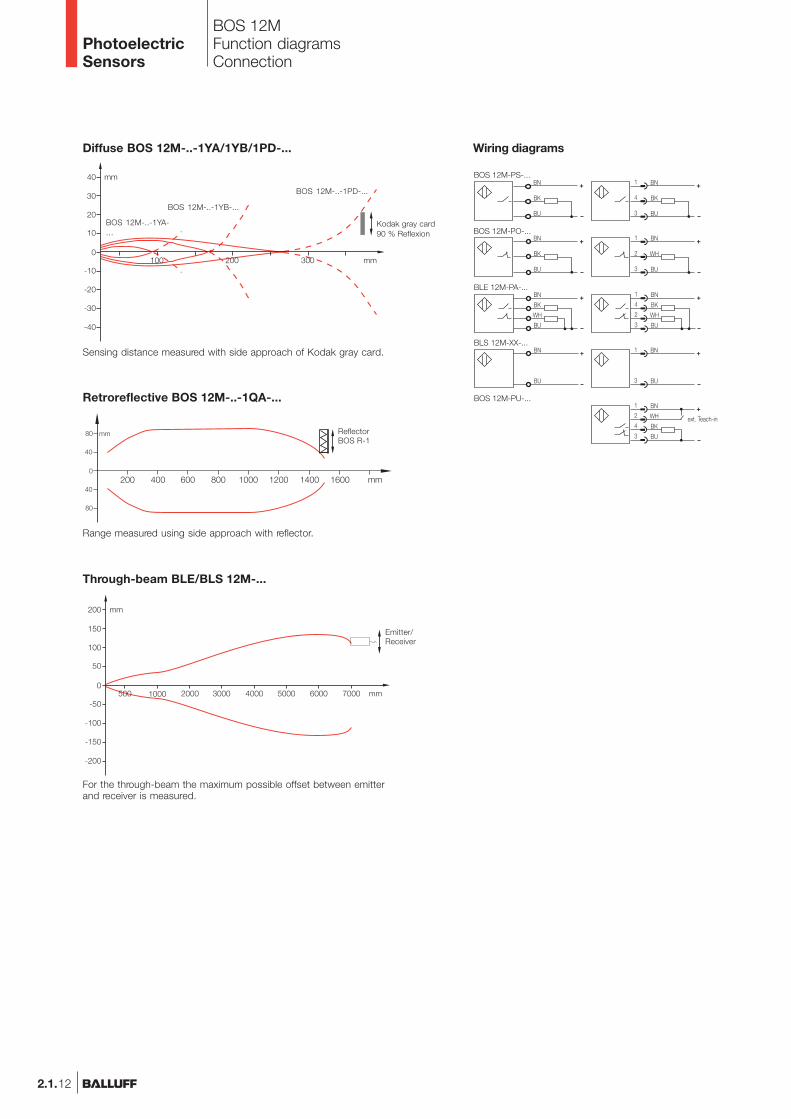
BOS 12MFunction diagramsConnection
Kodak gray card90 % Reflexion
BOS 12M-..-1YA-...
BOS 12M-..-1YB-...
BOS 12M-..-1PD-...
Emitter/Receiver
Diffuse BOS 12M-..-1YA/1YB/1PD-...
Through-beam BLE/BLS 12M-...
Retroreflective BOS 12M-..-1QA-...
ReflectorBOS R-1
Sensing distance measured with side approach of Kodak gray card.
Range measured using side approach with reflector.
For the through-beam the maximum possible offset between emitterand receiver is measured.
Wiring diagrams
PhotoelectricSensors
2.1.13
2.1
Photoelectricsensorsaccessoriespage 2.3.2 ...
2.3
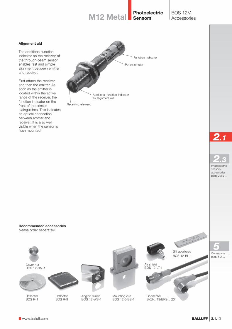
Alignment aid
The additional functionindicator on the receiver ofthe through-beam sensorenables fast and simplealignment between emitterand receiver.
First attach the receiverand then the emitter. Assoon as the emitter islocated within the activerange of the receiver, thefunction indicator on thefront of the sensorextinguishes. This indicatesan optical connectionbetween emitter andreceiver. It is also wellvisible when the sensor isflush mounted.
Additional function indicatoras alignment aid
Receiving element
Function indicator
Potentiometer
Recommended accessoriesplease order separately
Cover nutBOS 12-SM-1
ConnectorBKS-_ 19/BKS-_ 20
Angled mirrorBOS 12-WS-1
Mounting cuffBOS 12.0-BS-1
Air shieldBOS 12-LT-1
ReflectorBOS R-9
Slit aperturesBOS 12-BL-1
ReflectorBOS R-1
BOS 12MAccessoriesM12 Metal
www.balluff.com
Connectors ...page 5.2 ...
5
PhotoelectricSensors
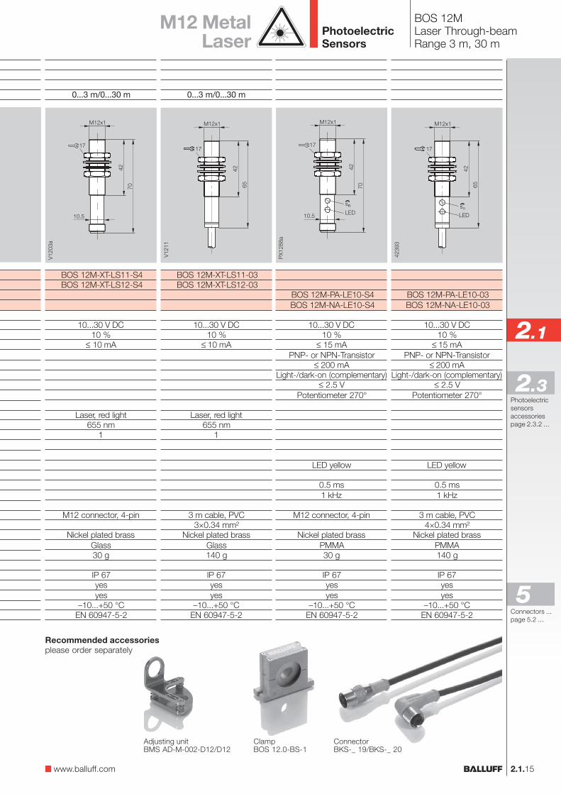
Laser through-beam Range
Through-beamEmitter High resolution 50 µm at focus
Long range 30 mReceiver PNP
NPNElectrical dataSupply voltage UB
RippleNo-load supply current I0 max.Switching outputOutput currentSwitching typeVoltage drop Ud at IeSettingsOptical dataEmitter, light typeWavelengthLaser classLight spot diameterIndicatorsOutput function indicatorTime dataResponse timeSwitching frequency fMechanical dataConnectionNo. of wires × cross-sectionHousing materialOptical surfaceWeightAmbient dataDegree of protection per IEC 60529Polarity reversal protectedShort circuit protectedAmbient temperature range Ta
Ambient light rejection
2.1.14
BOS 12MLaser Through-beamConnection
Emitter Receiver ReceiverBOS 12M-XT... BOS 12M-PA... BOS 12M-NA...
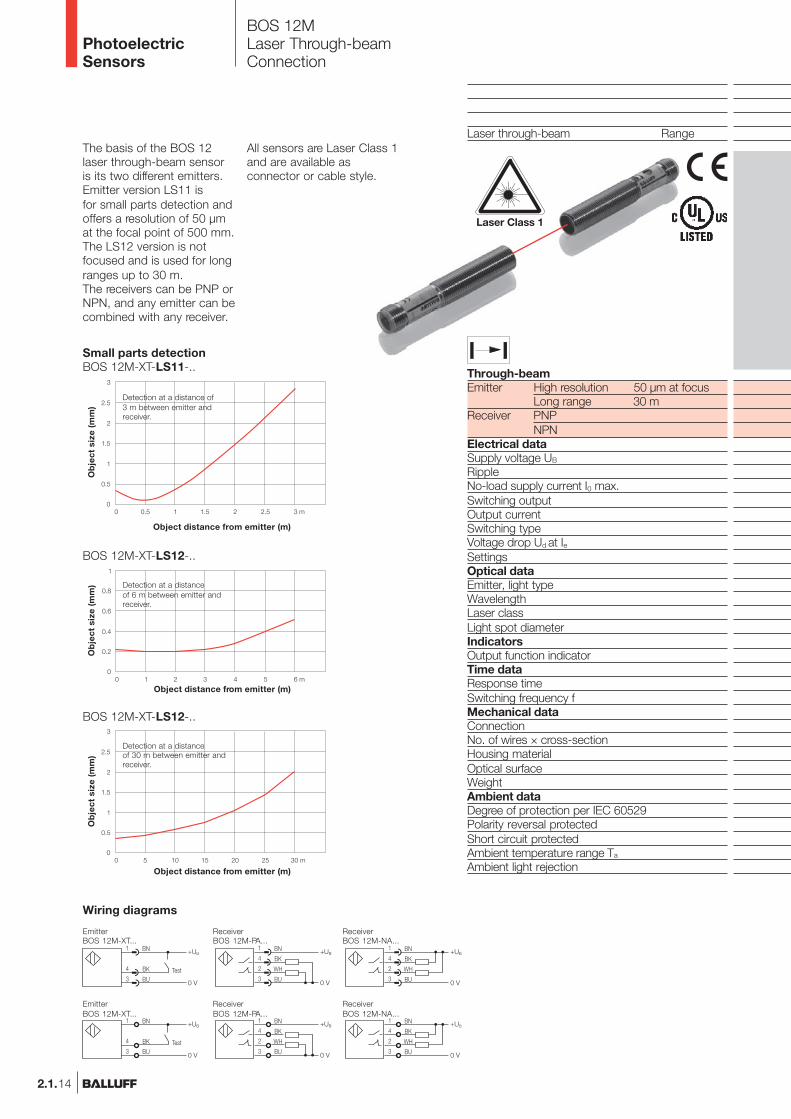
The basis of the BOS 12laser through-beam sensoris its two different emitters.Emitter version LS11 isfor small parts detection andoffers a resolution of 50 µmat the focal point of 500 mm.The LS12 version is notfocused and is used for longranges up to 30 m.The receivers can be PNP orNPN, and any emitter can becombined with any receiver.
Wiring diagrams
Emitter Receiver ReceiverBOS 12M-XT... BOS 12M-PA... BOS 12M-NA...
Laser Class 1
Ob
ject
siz
e (m
m)
Ob
ject
siz
e (m
m)
Ob
ject
siz
e (m
m)
Small parts detectionBOS 12M-XT-LS11-..
BOS 12M-XT-LS12-..
BOS 12M-XT-LS12-..
Object distance from emitter (m)
Object distance from emitter (m)
Object distance from emitter (m)
Detection at a distance of3 m between emitter andreceiver.
Detection at a distanceof 30 m between emitter andreceiver.
Detection at a distanceof 6 m between emitter andreceiver.
All sensors are Laser Class 1and are available asconnector or cable style.
PhotoelectricSensors
2.1.15
2.1
Photoelectricsensorsaccessoriespage 2.3.2 ...
2.3
www.balluff.com
Connectors ...page 5.2 ...
5
BOS 12M-PA-LE10-S4BOS 12M-NA-LE10-S4
10...30 V DC10 %
≤ 15 mAPNP- or NPN-Transistor
≤ 200 mALight-/dark-on (complementary)
≤ 2.5 VPotentiometer 270°
LED yellow
0.5 ms1 kHz
M12 connector, 4-pin
Nickel plated brassPMMA30 g
IP 67yesyes
–10...+50 °CEN 60947-5-2
0...3 m/0...30 m
BOS 12M-XT-LS11-S4BOS 12M-XT-LS12-S4
10...30 V DC10 %
≤ 10 mA
Laser, red light655 nm
1
M12 connector, 4-pin
Nickel plated brassGlass30 g
IP 67yesyes
–10...+50 °CEN 60947-5-2
M12 MetalLaser
BOS 12M-PA-LE10-03BOS 12M-NA-LE10-03
10...30 V DC10 %
≤ 15 mAPNP- or NPN-Transistor
≤ 200 mALight-/dark-on (complementary)
≤ 2.5 VPotentiometer 270°
LED yellow
0.5 ms1 kHz
3 m cable, PVC4×0.34 mm²
Nickel plated brassPMMA140 g
IP 67yesyes
–10...+50 °CEN 60947-5-2
0...3 m/0...30 m
BOS 12M-XT-LS11-03BOS 12M-XT-LS12-03
10...30 V DC10 %
≤ 10 mA
Laser, red light655 nm
1
3 m cable, PVC3×0.34 mm²
Nickel plated brassGlass140 g
IP 67yesyes
–10...+50 °CEN 60947-5-2
BOS 12MLaser Through-beamRange 3 m, 30 m
ClampBOS 12.0-BS-1
ConnectorBKS-_ 19/BKS-_ 20
Recommended accessoriesplease order separately
PhotoelectricSensors
Adjusting unitBMS AD-M-002-D12/D12
2.1.16
Features
– Supply voltage10...30 V DC, polarityreversal protected
– Output short circuitprotected
– Degree of protection IP 67– High resistance to
ambient light and pulsespikes
Applications
– Non-contactthrough-beam sensing
– Packaging– Parts counting– Small parts detection– Assembly and handling
automation– Conveying– Machine tool building
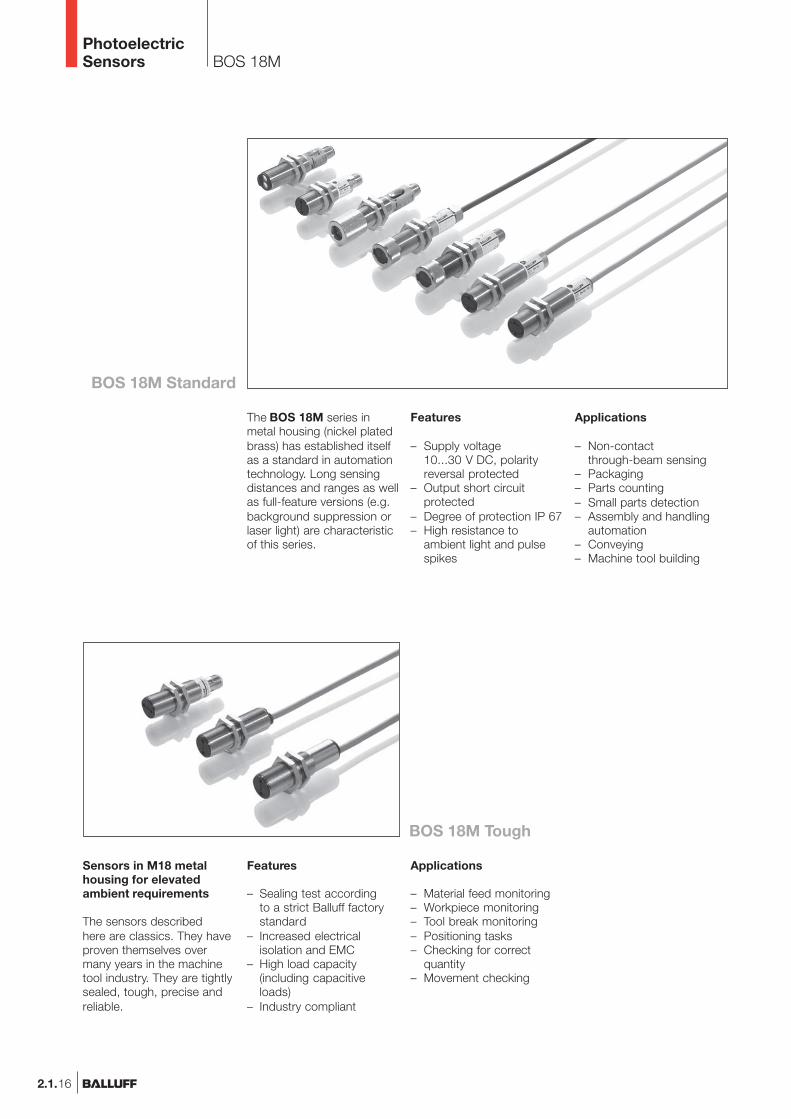
The BOS 18M series inmetal housing (nickel platedbrass) has established itselfas a standard in automationtechnology. Long sensingdistances and ranges as wellas full-feature versions (e.g.background suppression orlaser light) are characteristicof this series.
Sensors in M18 metalhousing for elevatedambient requirements
The sensors describedhere are classics. They haveproven themselves overmany years in the machinetool industry. They are tightlysealed, tough, precise andreliable.
Features
– Sealing test accordingto a strict Balluff factorystandard
– Increased electricalisolation and EMC
– High load capacity(including capacitiveloads)
– Industry compliant
BOS 18M
Applications
– Material feed monitoring– Workpiece monitoring– Tool break monitoring– Positioning tasks– Checking for correct
quantity– Movement checking
PhotoelectricSensors
BOS 18M Standard
BOS 18M Tough
2.1.17
2.1
Photoelectricsensorsaccessoriespage 2.3.2 ...
2.3
BOS 18MM18 Metal
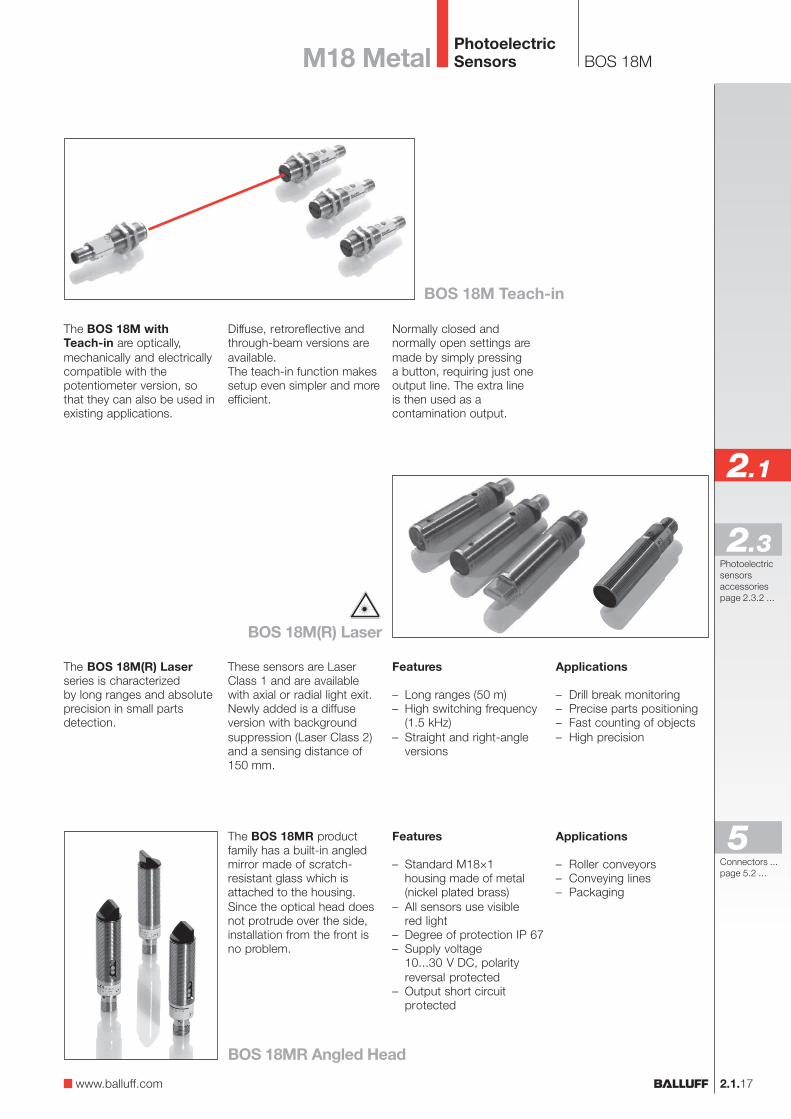
The BOS 18M withTeach-in are optically,mechanically and electricallycompatible with thepotentiometer version, sothat they can also be used inexisting applications.
Diffuse, retroreflective andthrough-beam versions areavailable.The teach-in function makessetup even simpler and moreefficient.
Normally closed andnormally open settings aremade by simply pressinga button, requiring just oneoutput line. The extra lineis then used as acontamination output.
The BOS 18M(R) Laserseries is characterizedby long ranges and absoluteprecision in small partsdetection.
The BOS 18MR productfamily has a built-in angledmirror made of scratch-resistant glass which isattached to the housing.Since the optical head doesnot protrude over the side,installation from the front isno problem.
Features
– Standard M18×1housing made of metal(nickel plated brass)
– All sensors use visiblered light
– Degree of protection IP 67– Supply voltage
10...30 V DC, polarityreversal protected
– Output short circuitprotected
Applications
– Roller conveyors– Conveying lines– Packaging
Features
– Long ranges (50 m)– High switching frequency
(1.5 kHz)– Straight and right-angle
versions
Applications
– Drill break monitoring– Precise parts positioning– Fast counting of objects– High precision
www.balluff.com
These sensors are LaserClass 1 and are availablewith axial or radial light exit.Newly added is a diffuseversion with backgroundsuppression (Laser Class 2)and a sensing distance of150 mm.
Connectors ...page 5.2 ...
5
PhotoelectricSensors
BOS 18M Teach-in
BOS 18M(R) Laser
BOS 18MR Angled Head
2.1.18
BOS 18MProduct Overview
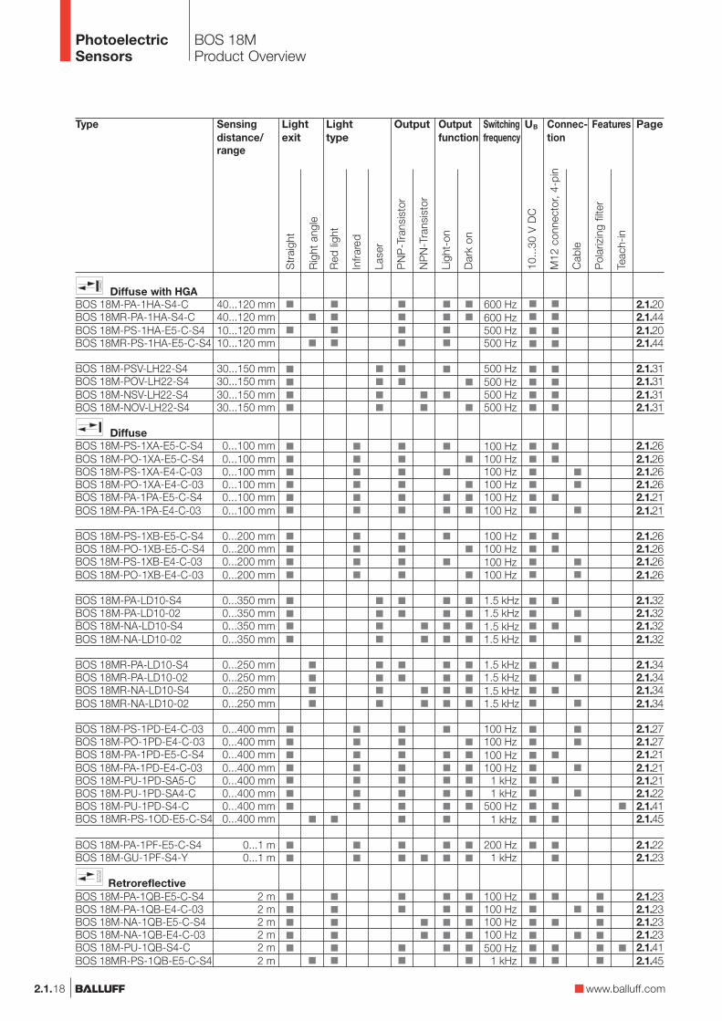
Type
Diffuse with HGABOS 18M-PA-1HA-S4-CBOS 18MR-PA-1HA-S4-CBOS 18M-PS-1HA-E5-C-S4BOS 18MR-PS-1HA-E5-C-S4
BOS 18M-PSV-LH22-S4BOS 18M-POV-LH22-S4BOS 18M-NSV-LH22-S4BOS 18M-NOV-LH22-S4
DiffuseBOS 18M-PS-1XA-E5-C-S4BOS 18M-PO-1XA-E5-C-S4BOS 18M-PS-1XA-E4-C-03BOS 18M-PO-1XA-E4-C-03BOS 18M-PA-1PA-E5-C-S4BOS 18M-PA-1PA-E4-C-03
BOS 18M-PS-1XB-E5-C-S4BOS 18M-PO-1XB-E5-C-S4BOS 18M-PS-1XB-E4-C-03BOS 18M-PO-1XB-E4-C-03
BOS 18M-PA-LD10-S4BOS 18M-PA-LD10-02BOS 18M-NA-LD10-S4BOS 18M-NA-LD10-02
BOS 18MR-PA-LD10-S4BOS 18MR-PA-LD10-02BOS 18MR-NA-LD10-S4BOS 18MR-NA-LD10-02
BOS 18M-PS-1PD-E4-C-03BOS 18M-PO-1PD-E4-C-03BOS 18M-PA-1PD-E5-C-S4BOS 18M-PA-1PD-E4-C-03BOS 18M-PU-1PD-SA5-CBOS 18M-PU-1PD-SA4-CBOS 18M-PU-1PD-S4-CBOS 18MR-PS-1OD-E5-C-S4
BOS 18M-PA-1PF-E5-C-S4BOS 18M-GU-1PF-S4-Y
RetroreflectiveBOS 18M-PA-1QB-E5-C-S4BOS 18M-PA-1QB-E4-C-03BOS 18M-NA-1QB-E5-C-S4BOS 18M-NA-1QB-E4-C-03BOS 18M-PU-1QB-S4-CBOS 18MR-PS-1QB-E5-C-S4
OutputLightexit
Sensingdistance/range
40...120 mm40...120 mm10...120 mm10...120 mm
30...150 mm30...150 mm30...150 mm30...150 mm
0...100 mm0...100 mm0...100 mm0...100 mm0...100 mm0...100 mm
0...200 mm0...200 mm0...200 mm0...200 mm
0...350 mm0...350 mm0...350 mm0...350 mm
0...250 mm0...250 mm0...250 mm0...250 mm
0...400 mm0...400 mm0...400 mm0...400 mm0...400 mm0...400 mm0...400 mm0...400 mm
0...1 m0...1 m
2 m2 m2 m2 m2 m2 m
Connec-tion
600 Hz600 Hz500 Hz500 Hz
500 Hz500 Hz500 Hz500 Hz
100 Hz100 Hz100 Hz100 Hz100 Hz100 Hz
100 Hz100 Hz100 Hz100 Hz
1.5 kHz1.5 kHz1.5 kHz1.5 kHz
1.5 kHz1.5 kHz1.5 kHz1.5 kHz
100 Hz100 Hz100 Hz100 Hz
1 kHz1 kHz
500 Hz1 kHz
200 Hz1 kHz
100 Hz100 Hz100 Hz100 Hz500 Hz
1 kHz
Outputfunction
Page
2.1.202.1.442.1.202.1.44
2.1.312.1.312.1.312.1.31
2.1.262.1.262.1.262.1.262.1.212.1.21
2.1.262.1.262.1.262.1.26
2.1.322.1.322.1.322.1.32
2.1.342.1.342.1.342.1.34
2.1.272.1.272.1.212.1.212.1.212.1.222.1.412.1.45
2.1.222.1.23
2.1.232.1.232.1.232.1.232.1.412.1.45
Features
Str
aigh
t
Rig
ht a
ngle
M12
con
nect
or, 4
-pin
Cab
le
10...
30 V
DC
Pol
ariz
ing
filte
r
NP
N-T
rans
isto
r
PN
P-T
rans
isto
r
Ligh
t-on
Dar
k on
UBSwitchingfrequency
Teac
h-in
Red
ligh
t
Lighttype
Lase
r
Infra
red
www.balluff.com
PhotoelectricSensors
2.1.19
2.1
Photoelectricsensorsaccessoriespage 2.3.2 ...
2.3
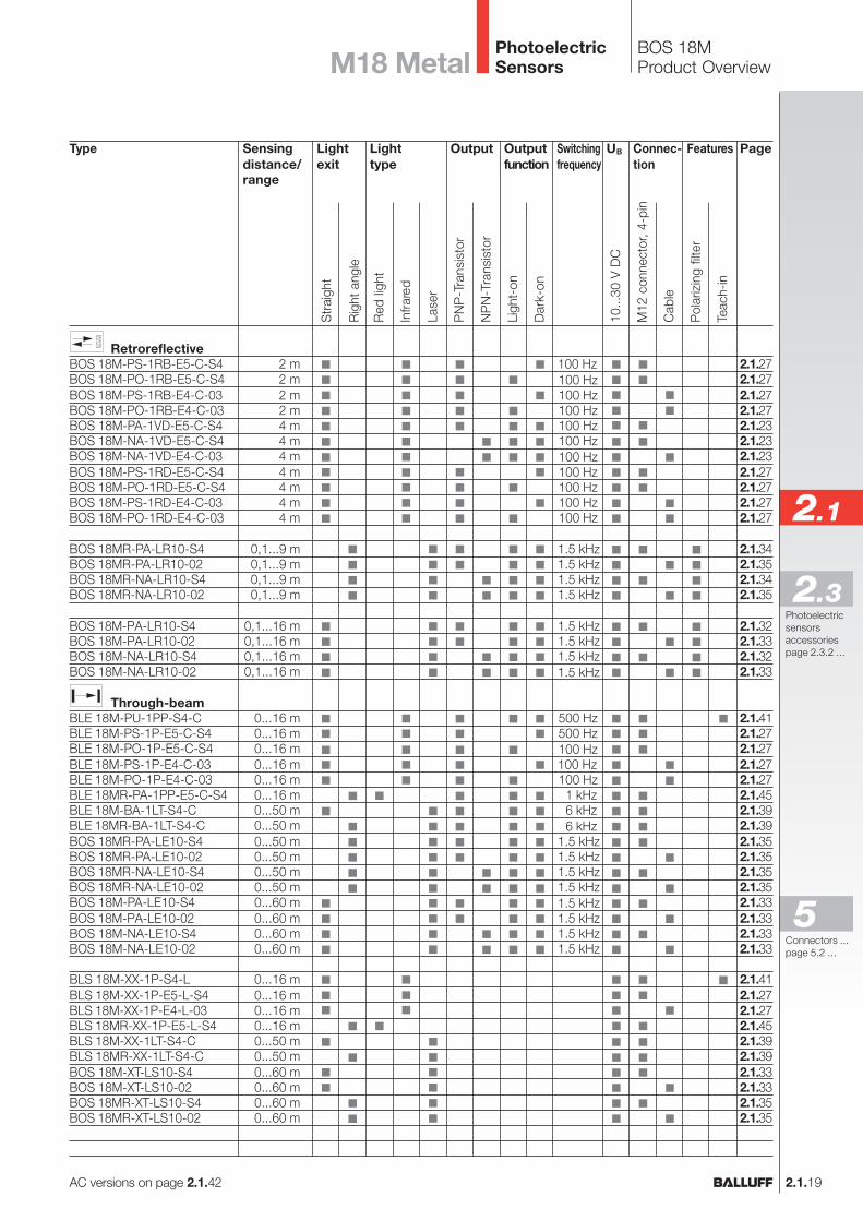
BOS 18MProduct OverviewM18 Metal
AC versions on page 2.1.42
Type
RetroreflectiveBOS 18M-PS-1RB-E5-C-S4BOS 18M-PO-1RB-E5-C-S4BOS 18M-PS-1RB-E4-C-03BOS 18M-PO-1RB-E4-C-03BOS 18M-PA-1VD-E5-C-S4BOS 18M-NA-1VD-E5-C-S4BOS 18M-NA-1VD-E4-C-03BOS 18M-PS-1RD-E5-C-S4BOS 18M-PO-1RD-E5-C-S4BOS 18M-PS-1RD-E4-C-03BOS 18M-PO-1RD-E4-C-03
BOS 18MR-PA-LR10-S4BOS 18MR-PA-LR10-02BOS 18MR-NA-LR10-S4BOS 18MR-NA-LR10-02
BOS 18M-PA-LR10-S4BOS 18M-PA-LR10-02BOS 18M-NA-LR10-S4BOS 18M-NA-LR10-02
Through-beamBLE 18M-PU-1PP-S4-CBLE 18M-PS-1P-E5-C-S4BLE 18M-PO-1P-E5-C-S4BLE 18M-PS-1P-E4-C-03BLE 18M-PO-1P-E4-C-03BLE 18MR-PA-1PP-E5-C-S4BLE 18M-BA-1LT-S4-CBLE 18MR-BA-1LT-S4-CBOS 18MR-PA-LE10-S4BOS 18MR-PA-LE10-02BOS 18MR-NA-LE10-S4BOS 18MR-NA-LE10-02BOS 18M-PA-LE10-S4BOS 18M-PA-LE10-02BOS 18M-NA-LE10-S4BOS 18M-NA-LE10-02
BLS 18M-XX-1P-S4-LBLS 18M-XX-1P-E5-L-S4BLS 18M-XX-1P-E4-L-03BLS 18MR-XX-1P-E5-L-S4BLS 18M-XX-1LT-S4-CBLS 18MR-XX-1LT-S4-CBOS 18M-XT-LS10-S4BOS 18M-XT-LS10-02BOS 18MR-XT-LS10-S4BOS 18MR-XT-LS10-02
OutputLightexit
Sensingdistance/range
2 m2 m2 m2 m4 m4 m4 m4 m4 m4 m4 m
0,1...9 m0,1...9 m0,1...9 m0,1...9 m
0,1...16 m0,1...16 m0,1...16 m0,1...16 m
0...16 m0...16 m0...16 m0...16 m0...16 m0...16 m0...50 m0...50 m0...50 m0...50 m0...50 m0...50 m0...60 m0...60 m0...60 m0...60 m
0...16 m0...16 m0...16 m0...16 m0...50 m0...50 m0...60 m0...60 m0...60 m0...60 m
Connec-tion
100 Hz100 Hz100 Hz100 Hz100 Hz100 Hz100 Hz100 Hz100 Hz100 Hz100 Hz
1.5 kHz1.5 kHz1.5 kHz1.5 kHz
1.5 kHz1.5 kHz1.5 kHz1.5 kHz
500 Hz500 Hz100 Hz100 Hz100 Hz
1 kHz6 kHz6 kHz
1.5 kHz1.5 kHz1.5 kHz1.5 kHz1.5 kHz1.5 kHz1.5 kHz1.5 kHz
Outputfunction
Page
2.1.272.1.272.1.272.1.272.1.232.1.232.1.232.1.272.1.272.1.272.1.27
2.1.342.1.352.1.342.1.35
2.1.322.1.332.1.322.1.33
2.1.412.1.272.1.272.1.272.1.272.1.452.1.392.1.392.1.352.1.352.1.352.1.352.1.332.1.332.1.332.1.33
2.1.412.1.272.1.272.1.452.1.392.1.392.1.332.1.332.1.352.1.35
Features
Str
aigh
t
Rig
ht a
ngle
M12
con
nect
or, 4
-pin
Cab
le
10...
30 V
DC
Pol
ariz
ing
filte
r
NP
N-T
rans
isto
r
PN
P-T
rans
isto
r
Ligh
t-on
Dar
k-on
UBSwitchingfrequency
Teac
h-in
Red
ligh
t
Lighttype
Lase
r
Infra
red
Connectors ...page 5.2 ...
5
PhotoelectricSensors
2.1.20
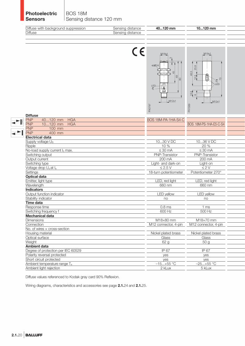
Diffuse with background suppression Sensing distanceDiffuse Sensing distance
DiffusePNP 40...120 mm HGAPNP 10...120 mm HGAPNP 100 mmPNP 400 mmElectrical dataSupply voltage UB
RippleNo-load supply current I0 max.Switching outputOutput currentSwitching typeVoltage drop Ud at IeSettingsOptical dataEmitter, light typeWavelengthIndicatorsOutput function indicatorStability indicatorTime dataResponse timeSwitching frequency fMechanical dataDimensionsConnectionNo. of wires × cross-sectionHousing materialOptical surfaceWeightAmbient dataDegree of protection per IEC 60529Polarity reversal protectedShort circuit protectedAmbient temperature range Ta
Ambient light rejection
BOS 18MSensing distance 120 mm
10...120 mm
BOS 18M-PS-1HA-E5-C-S4
10...36 V DC20 %
≤ 30 mAPNP-Transistor
200 mALight-on
≤ 2 VPotentiometer 270°
LED, red light660 nm
LED yellowno
1 ms500 Hz
M18×70 mmM12 connector, 4-pin
Nickel plated brassGlass50 g
IP 67yesyes
–25...+55 °C5 kLux
Diffuse values referenced to Kodak gray card 90% Reflexion.
Wiring diagrams, characteristics and accessories see page 2.1.24 and 2.1.25.
40...120 mm
BOS 18M-PA-1HA-S4-C
10...30 V DC10 %
≤ 30 mAPNP-Transistor
200 mALight- and dark-on
≤ 2.5 V18-turn potentiometer
LED, red light660 nm
LED yellowno
0.8 ms600 Hz
M18×80 mmM12 connector, 4-pin
Nickel plated brassGlass62 g
IP 67yesyes
–15...+55 °C2 kLux
PhotoelectricSensors
2.1.21
2.1
Photoelectricsensorsaccessoriespage 2.3.2 ...
2.3
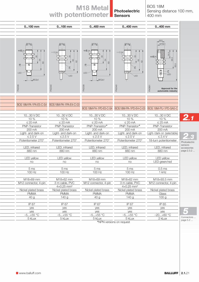
BOS 18MSensing distance 100 mm,400 mm
0...100 mm
BOS 18M-PA-1PA-E5-C-S4
10...30 V DC10 %
≤ 20 mAPNP-Transistor
200 mALight- and dark-on
≤ 2.5 VPotentiometer 270°
LED, infrared880 nm
LED yellowno
5 ms100 Hz
M18×69 mmM12 connector, 4-pin
Nickel plated brassPMMA40 g
IP 67yesyes
–5...+55 °C5 kLux
0...100 mm
BOS 18M-PA-1PA-E4-C-03
10...30 V DC10 %
≤ 20 mAPNP-Transistor
200 mALight- and dark-on
≤ 2.5 VPotentiometer 270°
LED, infrared880 nm
LED yellowno
5 ms100 Hz
M18×62 mm3 m cable, PVC
4×0.25 mm²Nickel plated brass
PMMA140 g
IP 67yesyes
–5...+55 °C5 kLux
M18 Metalwith potentiometer
0...400 mm
BOS 18M-PA-1PD-E5-C-S4
10...30 V DC10 %
≤ 20 mAPNP-Transistor*
200 mALight- and dark-on
≤ 2.5 VPotentiometer 270°
LED, infrared880 nm
LED yellowno
5 ms100 Hz
M18×69 mmM12 connector, 4-pin
Nickel plated brassPMMA40 g
IP 67yesyes
–5...+55 °C5 kLux
0...400 mm
BOS 18M-PA-1PD-E4-C-03
10...30 V DC10 %
≤ 20 mAPNP-Transistor*
200 mALight- and dark-on
≤ 2.5 VPotentiometer 270°
LED, infrared880 nm
LED yellowno
5 ms100 Hz
M18×62 mm3 m cable, PVC
4×0.25 mm²Nickel plated brass
PMMA140 g
IP 67yesyes
–5...+55 °C5 kLux
0...400 mm
BOS 18M-PU-1PD-SA5-C
10...30 V DC10 %
≤ 25 mAPNP-Transistor
200 mALight-/dark-on (selectable)
≤ 2.4 V18-turn potentiometer
LED, infrared880 nm
LED yellowLED green/red
0.5 ms1 kHz
M18×93.5 mmM12 connector, 4-pin
Nickel plated brassGlass100 g
IP 65yesyes
–20...+60 °C2 kLux
Approval for theautomobile industry
*NPN versions on request
www.balluff.com
Connectors ...page 5.2 ...
5
PhotoelectricSensors

2.1.22
BOS 18MSensing distance 400 mm, 1 m
Diffuse values referenced to Kodak gray card 90% Reflexion.Retroreflective values referenced to R1 reflector.
Wiring diagrams, characteristics and accessories see page 2.1.24 and 2.1.25.
0...400 mm
BOS 18M-PU-1PD-SA4-C
10...30 V DC10 %
≤ 25 mAPNP-Transistor
200 mALight-/dark-on (selectable)
≤ 2.4 V18-turn potentiometer
LED, infrared880 nm
LED yellowLED green/red
0.5 ms1 kHz
M18×95 mm3 m cable, PVC
3×0.25 mm²Nickel plated brass
Glass200 g
IP 65yesyes
–20...+60 °C2 kLux
Approval for theautomobile industry
Diffuse Sensing distanceRetroreflective Range
DiffusePNP 400 mmPNP 1 mPNP/NPN 1 mRetroreflectivePNP 2 m Polarizing filterNPN 2 m Polarizing filterPNP 4 mNPN 4 mElectrical dataSupply voltage UB
RippleNo-load supply current I0 max.Switching outputOutput currentSwitching typeVoltage drop Ud at IeSettingsOptical dataEmitter, light typeWavelengthIndicatorsOutput function indicatorStability indicatorTime dataResponse timeSwitching frequency fMechanical dataDimensionsConnectionNo. of wires × cross-sectionHousing materialOptical surfaceWeightAmbient dataDegree of protection per IEC 60529Polarity reversal protectedShort circuit protectedAmbient temperature range Ta
Ambient light rejection
0...1 m
BOS 18M-PA-1PF-E5-C-S4
10...30 V DC10 %
≤ 20 mAPNP-Transistor
200 mALight- and dark-on
≤ 2.5 VPotentiometer 270°
LED, infrared880 nm
LED yellowno
2.5 ms200 Hz
M18×69 mmM12 connector, 4-pin
Nickel plated brassPMMA40 g
IP 67yesyes
–5...+55 °C5 kLux
PhotoelectricSensors
2.1.23
2.1
Photoelectricsensorsaccessoriespage 2.3.2 ...
2.3
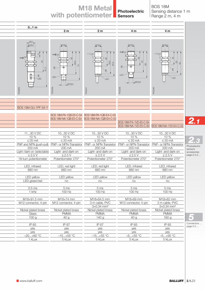
BOS 18MSensing distance 1 mRange 2 m, 4 m
0...1 m
BOS 18M-GU-1PF-S4-Y
11...30 V DC10 %
≤ 25 mAPNP and NPN (push-pull)
200 mALight-/dark-on (selectable)
≤ 2.5 V18-turn potentiometer
LED, infrared880 nm
LED yellowLED green/red
0.5 ms1 kHz
M18×91.5 mmM12 connector, 4-pin
Nickel plated brassGlass100 g
IP 65yesyes
–20...+60 °C1 kLux
2 m
BOS 18M-PA-1QB-E5-C-S4BOS 18M-NA-1QB-E5-C-S4
10...30 V DC10 %
≤ 20 mAPNP- or NPN-Transistor
200 mALight- and dark-on
≤ 2.5 VPotentiometer 270°
LED, red light660 nm
LED yellowno
5 ms100 Hz
M18×74 mmM12 connector, 4-pin
Nickel plated brassPMMA40 g
IP 67yesyes
–15...+55 °C5 kLux
2 m
BOS 18M-PA-1QB-E4-C-03BOS 18M-NA-1QB-E4-C-03
10...30 V DC10 %
≤ 20 mAPNP- or NPN-Transistor
200 mALight- and dark-on
≤ 2.5 VPotentiometer 270°
LED, red light660 nm
LED yellowno
5 ms100 Hz
M18×64.5 mm3 m cable, PVC
3×0.34 mm²Nickel plated brass
PMMA140 g
IP 67yesyes
–15...+55 °C5 kLux
4 m
BOS 18M-PA-1VD-E5-C-S4BOS 18M-NA-1VD-E5-C-S4
10...30 V DC10 %
≤ 20 mAPNP- or NPN-Transistor
200 mALight- and dark-on
≤ 2.5 VPotentiometer 270°
LED, infrared880 nm
LED yellowno
5 ms100 Hz
M18×69 mmM12 connector, 4-pin
Nickel plated brassPMMA40 g
IP 65yesyes
–5...+55 °C5 kLux
4 m
BOS 18M-NA-1VD-E4-C-03
10...30 V DC10 %
≤ 20 mAPNP- or NPN-Transistor
200 mALight- and dark-on
≤ 2.5 VPotentiometer 270°
LED, infrared880 nm
LED yellowno
5 ms100 Hz
M18×62 mm3 m cable, PVC
3×0.34 mm²Nickel plated brass
PMMA160 g
IP 65yesyes
–5...+55 °C5 kLux
M18 Metalwith potentiometer
www.balluff.com
Connectors ...page 5.2 ...
5
PhotoelectricSensors
2.1.24
BOS 18MFunction diagrams
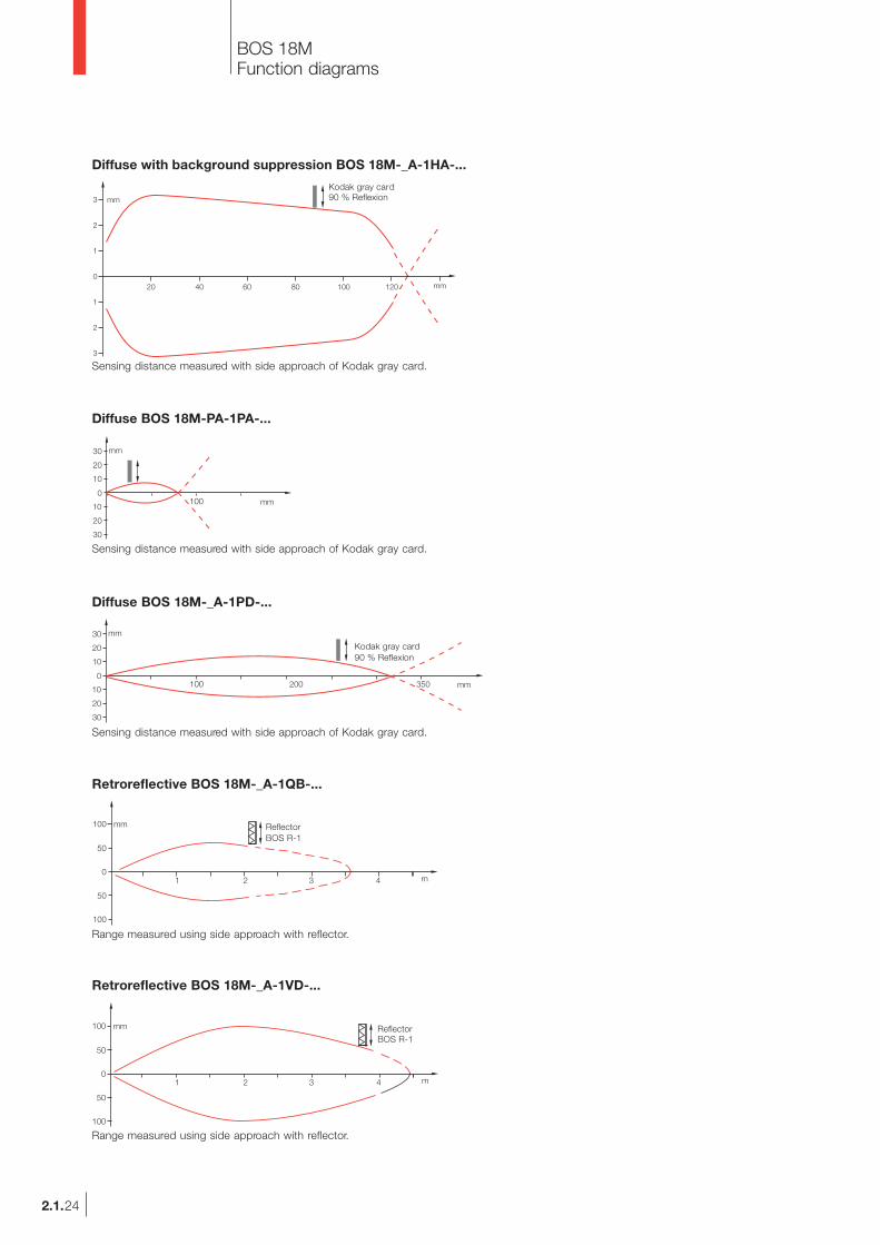
Diffuse with background suppression BOS 18M-_A-1HA-...
Kodak gray card90 % Reflexion
Sensing distance measured with side approach of Kodak gray card.
Diffuse BOS 18M-PA-1PA-...
Sensing distance measured with side approach of Kodak gray card.
Diffuse BOS 18M-_A-1PD-...
Kodak gray card90 % Reflexion
Sensing distance measured with side approach of Kodak gray card.
Retroreflective BOS 18M-_A-1QB-...
ReflectorBOS R-1
Range measured using side approach with reflector.
Retroreflective BOS 18M-_A-1VD-...
ReflectorBOS R-1
Range measured using side approach with reflector.
Kodak gray card90 % Reflexion
PhotoelectricSensors
2.1.25
2.1
Photoelectricsensorsaccessoriespage 2.3.2 ...
2.3
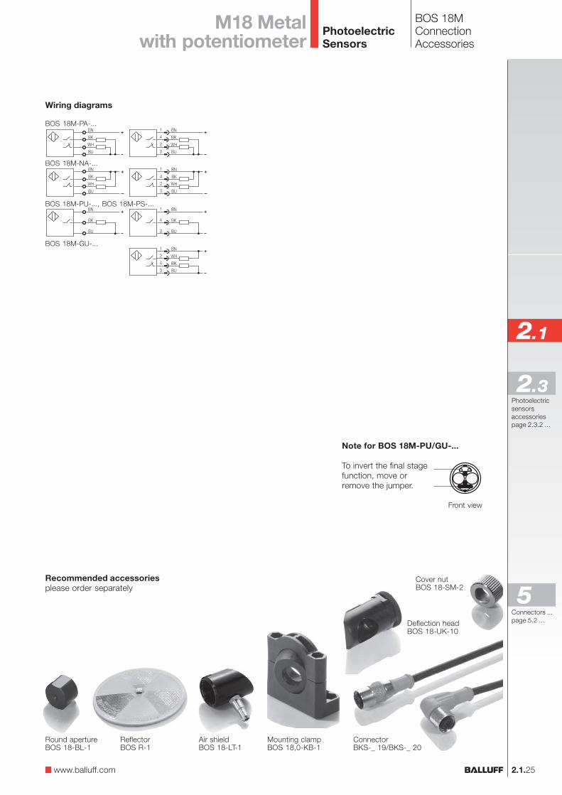
BOS 18MConnectionAccessories
Front view
Note for BOS 18M-PU/GU-...
To invert the final stagefunction, move orremove the jumper.
Wiring diagrams
BOS 18M-PA-...
BOS 18M-NA-...
BOS 18M-PU-..., BOS 18M-PS-...
BOS 18M-GU-...
M18 Metalwith potentiometer
Mounting clampBOS 18,0-KB-1
Round apertureBOS 18-BL-1
ReflectorBOS R-1
Cover nutBOS 18-SM-2
Air shieldBOS 18-LT-1
Deflection headBOS 18-UK-10
ConnectorBKS-_ 19/BKS-_ 20
Recommended accessoriesplease order separately
www.balluff.com
Connectors ...page 5.2 ...
5
PhotoelectricSensors
2.1.26
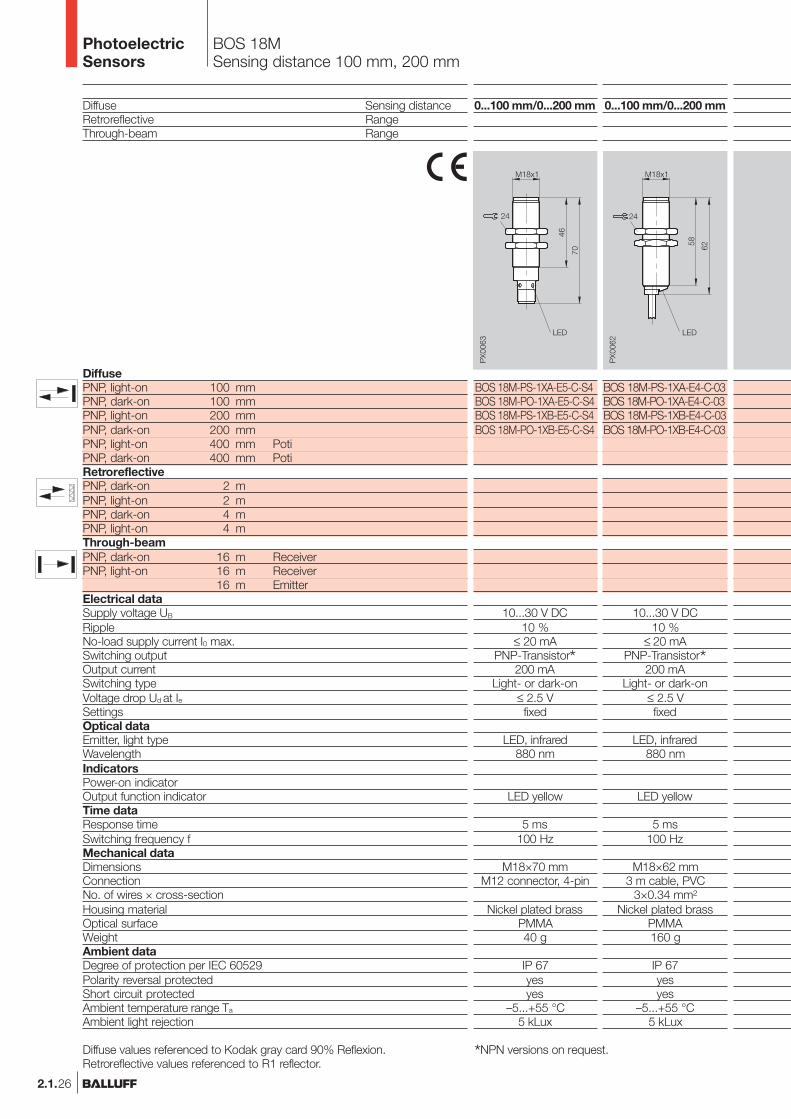
BOS 18MSensing distance 100 mm, 200 mm
0...100 mm/0...200 mm
BOS 18M-PS-1XA-E5-C-S4BOS 18M-PO-1XA-E5-C-S4BOS 18M-PS-1XB-E5-C-S4BOS 18M-PO-1XB-E5-C-S4
10...30 V DC10 %
≤ 20 mAPNP-Transistor*
200 mALight- or dark-on
≤ 2.5 Vfixed
LED, infrared880 nm
LED yellow
5 ms100 Hz
M18×70 mmM12 connector, 4-pin
Nickel plated brassPMMA40 g
IP 67yesyes
–5...+55 °C5 kLux
0...100 mm/0...200 mm
BOS 18M-PS-1XA-E4-C-03BOS 18M-PO-1XA-E4-C-03BOS 18M-PS-1XB-E4-C-03BOS 18M-PO-1XB-E4-C-03
10...30 V DC10 %
≤ 20 mAPNP-Transistor*
200 mALight- or dark-on
≤ 2.5 Vfixed
LED, infrared880 nm
LED yellow
5 ms100 Hz
M18×62 mm3 m cable, PVC
3×0.34 mm²Nickel plated brass
PMMA160 g
IP 67yesyes
–5...+55 °C5 kLux
Diffuse Sensing distanceRetroreflective RangeThrough-beam Range
DiffusePNP, light-on 100 mmPNP, dark-on 100 mmPNP, light-on 200 mmPNP, dark-on 200 mmPNP, light-on 400 mm PotiPNP, dark-on 400 mm PotiRetroreflectivePNP, dark-on 2 mPNP, light-on 2 mPNP, dark-on 4 mPNP, light-on 4 mThrough-beamPNP, dark-on 16 m ReceiverPNP, light-on 16 m Receiver
16 m EmitterElectrical dataSupply voltage UB
RippleNo-load supply current I0 max.Switching outputOutput currentSwitching typeVoltage drop Ud at IeSettingsOptical dataEmitter, light typeWavelengthIndicatorsPower-on indicatorOutput function indicatorTime dataResponse timeSwitching frequency fMechanical dataDimensionsConnectionNo. of wires × cross-sectionHousing materialOptical surfaceWeightAmbient dataDegree of protection per IEC 60529Polarity reversal protectedShort circuit protectedAmbient temperature range Ta
Ambient light rejection
Diffuse values referenced to Kodak gray card 90% Reflexion.Retroreflective values referenced to R1 reflector.
*NPN versions on request.
PhotoelectricSensors
2.1.27
2.1
Photoelectricsensorsaccessoriespage 2.3.2 ...
2.3
0...400 mm
BOS 18M-PS-1PD-E4-C-03BOS 18M-PO-1PD-E4-C-03
10...30 V DC10 %
≤ 20 mAPNP-Transistor*
200 mALight- or dark-on
≤ 2.5 V18-turn potentiometer
LED, infrared880 nm
LED yellow
5 ms100 Hz
M18×67.5 mm3 m cable, PVC
3×0.34 mm²Nickel plated brass
PMMA160 g
IP 67yesyes
–5...+55 °C2 kLux
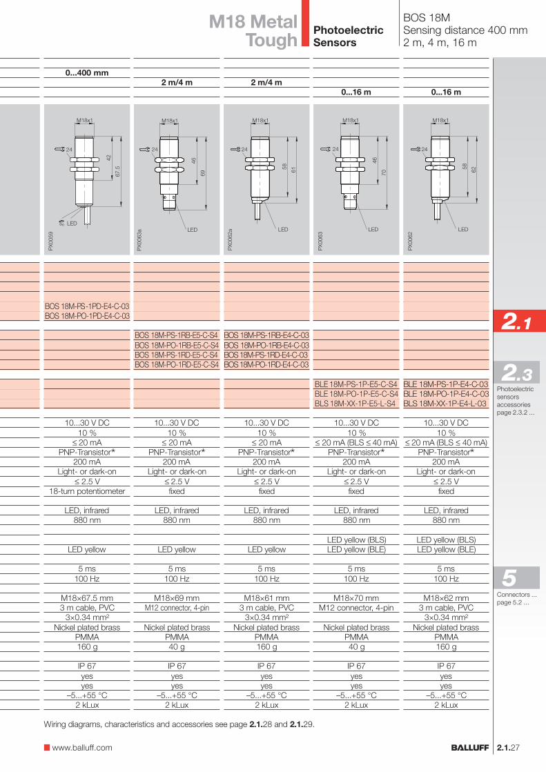
BOS 18MSensing distance 400 mm2 m, 4 m, 16 m
2 m/4 m
BOS 18M-PS-1RB-E5-C-S4BOS 18M-PO-1RB-E5-C-S4BOS 18M-PS-1RD-E5-C-S4BOS 18M-PO-1RD-E5-C-S4
10...30 V DC10 %
≤ 20 mAPNP-Transistor*
200 mALight- or dark-on
≤ 2.5 Vfixed
LED, infrared880 nm
LED yellow
5 ms100 Hz
M18×69 mmM12 connector, 4-pin
Nickel plated brassPMMA40 g
IP 67yesyes
–5...+55 °C2 kLux
2 m/4 m
BOS 18M-PS-1RB-E4-C-03BOS 18M-PO-1RB-E4-C-03BOS 18M-PS-1RD-E4-C-03BOS 18M-PO-1RD-E4-C-03
10...30 V DC10 %
≤ 20 mAPNP-Transistor*
200 mALight- or dark-on
≤ 2.5 Vfixed
LED, infrared880 nm
LED yellow
5 ms100 Hz
M18×61 mm3 m cable, PVC
3×0.34 mm²Nickel plated brass
PMMA160 g
IP 67yesyes
–5...+55 °C2 kLux
0...16 m
BLE 18M-PS-1P-E5-C-S4BLE 18M-PO-1P-E5-C-S4BLS 18M-XX-1P-E5-L-S4
10...30 V DC10 %
≤ 20 mA (BLS ≤ 40 mA)PNP-Transistor*
200 mALight- or dark-on
≤ 2.5 Vfixed
LED, infrared880 nm
LED yellow (BLS)LED yellow (BLE)
5 ms100 Hz
M18×70 mmM12 connector, 4-pin
Nickel plated brassPMMA40 g
IP 67yesyes
–5...+55 °C2 kLux
0...16 m
BLE 18M-PS-1P-E4-C-03BLE 18M-PO-1P-E4-C-03BLS 18M-XX-1P-E4-L-03
10...30 V DC10 %
≤ 20 mA (BLS ≤ 40 mA)PNP-Transistor*
200 mALight- or dark-on
≤ 2.5 Vfixed
LED, infrared880 nm
LED yellow (BLS)LED yellow (BLE)
5 ms100 Hz
M18×62 mm3 m cable, PVC
3×0.34 mm²Nickel plated brass
PMMA160 g
IP 67yesyes
–5...+55 °C2 kLux
M18 MetalTough
Wiring diagrams, characteristics and accessories see page 2.1.28 and 2.1.29.
www.balluff.com
Connectors ...page 5.2 ...
5
PhotoelectricSensors
2.1.28
BOS 18MFunction diagrams
Diffuse BOS 18M-P_-1XA-...
Sensing distance measured with side approach of Kodak gray card.
Diffuse BOS 18M-P_-1XB-...
Kodak gray card90 % Reflexion
Sensing distance measured with side approach of Kodak gray card.
Retroreflective BOS 18M-P_-1RB-...
ReflectorBOS R-1
Range measured using side approach with reflector.
Retroreflective BOS 18M-P_-1RD-...
ReflectorBOS R-1
Range measured using side approach with reflector.
Kodak gray card90 % Reflexion
Through-beam BLE/BLS 18M-...
For the through-beam the maximum possible offsetbetween emitter and receiver is measured.
Emitter/Receiver
Diffuse BOS 18M-P_-1PD-...
Kodak gray card90 % Reflexion
Sensing distance measured with side approach of Kodak gray card.
PhotoelectricSensors
2.1.29
2.1
Photoelectricsensorsaccessoriespage 2.3.2 ...
2.3
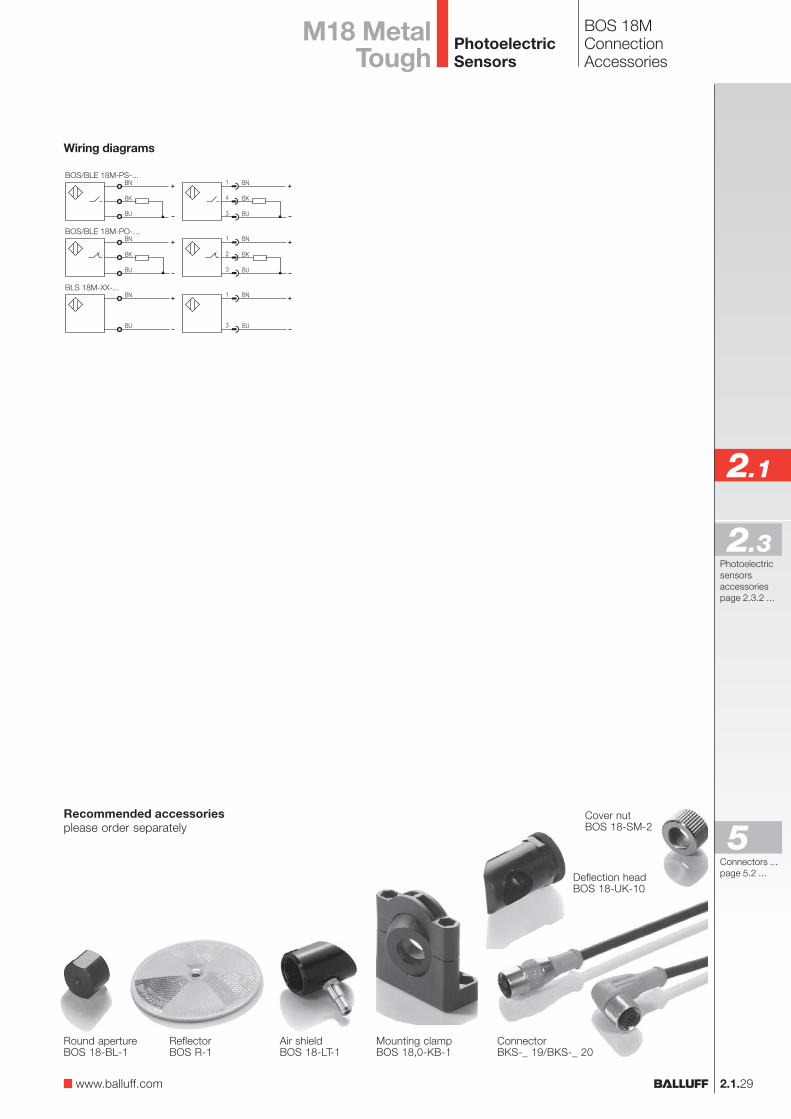
BOS 18MConnectionAccessories
Wiring diagrams
Mounting clampBOS 18,0-KB-1
Round apertureBOS 18-BL-1
ReflectorBOS R-1
Cover nutBOS 18-SM-2
Air shieldBOS 18-LT-1
Deflection headBOS 18-UK-10
ConnectorBKS-_ 19/BKS-_ 20
Recommended accessoriesplease order separately
M18 MetalTough
www.balluff.com
Connectors ...page 5.2 ...
5
PhotoelectricSensors

Recommended accessoriesplease order separately
Mounting clampBOS 18,0-KB-1
ConnectorBKS-_ 19/BKS-_ 20
2.1.30
BOS 18MLaser diffuseConnection, Function Diagram, Accessories
BOS 18M-PSV... BOS 18M-NSV...
Wiring diagrams
BOS 18M-POV... BOS 18M-NOV...
Indicators and operating elements
Red LEDThe red LED turns on when the sensor is working in anunsafe range. The red LED flashes when there is a shortcircuit on the output.Yellow LEDOutput function indication: The yellow LED comes on whenthe output is activeError outputThe error output is active when the sensor is working in anunsafe range.PotentiometerUsed for precise setting of the switching point andbackground suppression.
10-turn potentiometer forexact setting of the switching distance
Error indication (red LED)
Output function indication (yellow LED)
Gray scale shift
Sw
itch
ing
po
int
(mm
)
Object distance (mm)
Ob
ject
siz
e (m
m)
Æ L
aser
sp
ot
(mm
)
Turn-on point for lateral approach
Light spot diameter at distance
Smallest detectable part
Sr
max
(%)
Object distance (mm)
Object distance (mm)
Object distance (mm)
Kodak white 90 %
Kodak gray 18 %
Kodakblack 6 %
The new BOS 18M Laserdiffuse sensor withbackground suppression isideal for small partsdetection with objects assmall as 0.1 mm in diameter.The 10-turn potentiometerenables highly precisesetting of the backgroundsuppression. Incorrectmeasurements andcontamination are indicatedby an LED and the erroroutput.
PhotoelectricSensors
2.1.31
2.1
Photoelectricsensorsaccessoriespage 2.3.2 ...
2.3
Diffuse with background suppression Sensing distance
Diffuse with background suppressionPNP NO 30...150 mm HGANPN NO 30...150 mm HGAPNP NC 30...150 mm HGANPN NC 30...150 mm HGAElectrical dataSupply voltage UB
RippleNo-load supply current I0 max.Switching outputOutput currentSwitching typeVoltage drop Ud at IeSettingsError outputOptical dataEmitter, light typeWavelengthLaser classLight spot diameterIndicatorsOutput function indicatorError indicatorTime dataResponse timeSwitching frequency fMechanical dataDimensionsConnectionHousing materialOptical surfaceWeightAmbient dataDegree of protection per IEC 60529Polarity reversal protectedShort circuit protectedAmbient temperature range Ta
Ambient light rejection
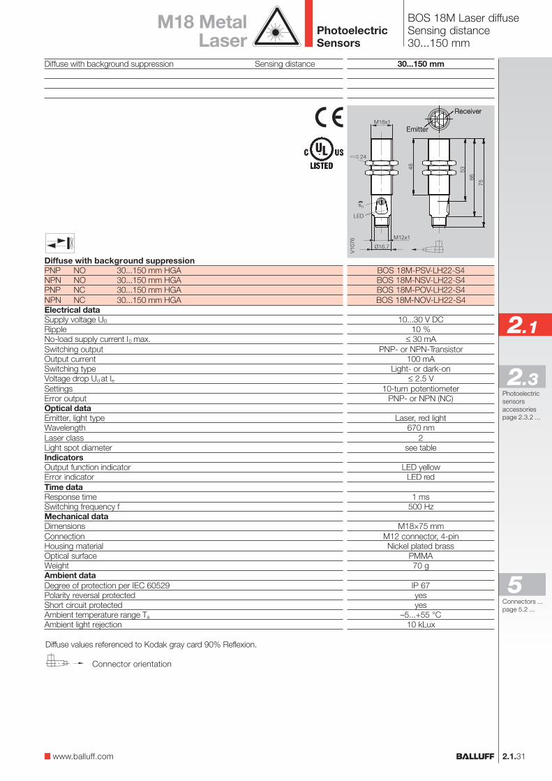
BOS 18M Laser diffuseSensing distance30...150 mm
30...150 mm
BOS 18M-PSV-LH22-S4BOS 18M-NSV-LH22-S4BOS 18M-POV-LH22-S4BOS 18M-NOV-LH22-S4
10...30 V DC10 %
≤ 30 mAPNP- or NPN-Transistor
100 mALight- or dark-on
≤ 2.5 V10-turn potentiometer
PNP- or NPN (NC)
Laser, red light670 nm
2see table
LED yellowLED red
1 ms500 Hz
M18×75 mmM12 connector, 4-pinNickel plated brass
PMMA70 g
IP 67yesyes
–5...+55 °C10 kLux
M18 MetalLaser
www.balluff.com
Connectors ...page 5.2 ...
5
Diffuse values referenced to Kodak gray card 90% Reflexion.
Connector orientation
Receiver
Emitter
V10
76
24
Ø16.7
48 53
66
75
M18x1
M12x1
LED
ns
Receiver
Emitter
PhotoelectricSensors
2.1.32
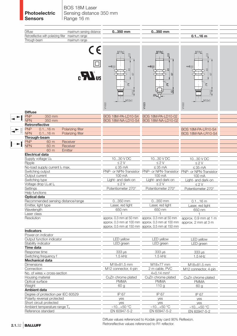
BOS 18M LaserSensing distance 350 mmRange 16 m
Diffuse maximum sensing distanceRetroreflective with polarizing filter maximum rangeThrough-beam maximum range
DiffusePNP 350 mmNPN 350 mmRetroreflectivePNP 0.1...16 m Polarizing filterNPN 0.1...16 m Polarizing filterThrough-beamPNP 60 m ReceiverNPN 60 m Receiver
60 m EmitterElectrical dataSupply voltage UB
RippleNo-load supply current I0 max.Switching outputOutput currentSwitching typeVoltage drop Ud at IeSettingsHelp functionsOptical dataRecommended sensing distance/rangeEmitter, light typeWavelengthLaser classResolution
IndicatorsPower-on indicatorOutput function indicatorStability indicatorTime dataResponse timeSwitching frequency fMechanical dataDimensionsConnectionNo. of wires × cross-sectionHousing materialOptical surfaceWeightAmbient dataDegree of protection per IEC 60529Polarity reversal protectedShort circuit protectedAmbient temperature range Ta
Reference standard
0...350 mm
BOS 18M-PA-LD10-S4BOS 18M-NA-LD10-S4
10...30 V DC≤ 2 V
≤ 35 mAPNP- or NPN-Transistor
100 mALight- and dark-on
≤ 2 VPotentiometer 270°
0...350 mmLaser, red light
650 nm1
approx. 0.3 mm at 50 mmapprox. 0.3 mm at 100 mmapprox. 0.5 mm at 150 mm
LED yellowLED green
333 µs1.5 kHz
M18×81.5 mmM12 connector, 4-pin
CuZn chrome platedPMMA60 g
IP 67yesyes
–10...+50 °CEN 60947-5-2
0.1...16 m
BOS 18M-PA-LR10-S4BOS 18M-NA-LR10-S4
10...30 V DC≤ 2 V
≤ 35 mAPNP- or NPN-Transistor
100 mALight- and dark-on
≤ 2 VPotentiometer 270°
0.1...16 mLaser, red light
650 nm1
approx. 0.9 mm at 1 mapprox. 2 mm at 3 m
LED yellowLED green
333 µs1.5 kHz
M18×81.5 mmM12 connector, 4-pin
CuZn chrome platedPMMA60 g
IP 67yesyes
–10...+50 °CEN 60947-5-2
0...350 mm
BOS 18M-PA-LD10-02BOS 18M-NA-LD10-02
10...30 V DC≤ 2 V
≤ 35 mAPNP- or NPN-Transistor
100 mALight- and dark-on
≤ 2 VPotentiometer 270°
0...350 mmLaser, red light
650 nm1
approx. 0.3 mm at 50 mmapprox. 0.3 mm at 100 mmapprox. 0.5 mm at 150 mm
LED yellowLED green
333 µs1.5 kHz
M18×77 mm2 m cable, PVC
4×0.14 mm²CuZn chrome plated
PMMA110 g
IP 67yesyes
–10...+50 °CEN 60947-5-2
Diffuse values referenced to Kodak gray card 90% Reflexion.Retroreflective values referenced to R1 reflector.
PhotoelectricSensors
�
2.1.33
2.1
Photoelectricsensorsaccessoriespage 2.3.2 ...
2.3
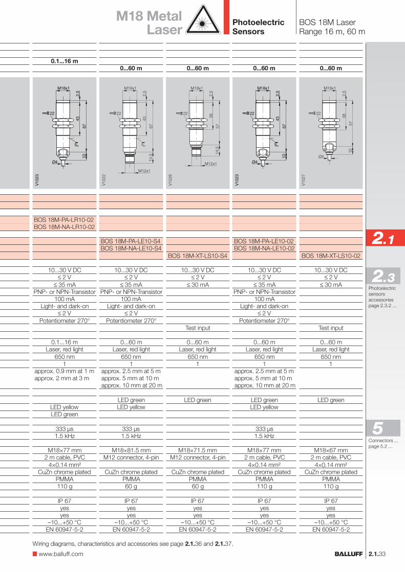
BOS 18M LaserRange 16 m, 60 m
0.1...16 m
BOS 18M-PA-LR10-02BOS 18M-NA-LR10-02
10...30 V DC≤ 2 V
≤ 35 mAPNP- or NPN-Transistor
100 mALight- and dark-on
≤ 2 VPotentiometer 270°
0.1...16 mLaser, red light
650 nm1
approx. 0.9 mm at 1 mapprox. 2 mm at 3 m
LED yellowLED green
333 µs1.5 kHz
M18×77 mm2 m cable, PVC
4×0.14 mm²CuZn chrome plated
PMMA110 g
IP 67yesyes
–10...+50 °CEN 60947-5-2
M18 MetalLaser
0...60 m
BOS 18M-PA-LE10-S4BOS 18M-NA-LE10-S4
10...30 V DC≤ 2 V
≤ 35 mAPNP- or NPN-Transistor
100 mALight- and dark-on
≤ 2 VPotentiometer 270°
0...60 mLaser, red light
650 nm1
approx. 2.5 mm at 5 mapprox. 5 mm at 10 mapprox. 10 mm at 20 m
LED greenLED yellow
333 µs1.5 kHz
M18×81.5 mmM12 connector, 4-pin
CuZn chrome platedPMMA60 g
IP 67yesyes
–10...+50 °CEN 60947-5-2
0...60 m
BOS 18M-PA-LE10-02BOS 18M-NA-LE10-02
10...30 V DC≤ 2 V
≤ 35 mAPNP- or NPN-Transistor
100 mALight- and dark-on
≤ 2 VPotentiometer 270°
0...60 mLaser, red light
650 nm1
approx. 2.5 mm at 5 mapprox. 5 mm at 10 mapprox. 10 mm at 20 m
LED greenLED yellow
333 µs1.5 kHz
M18×77 mm2 m cable, PVC
4×0.14 mm²CuZn chrome plated
PMMA110 g
IP 67yesyes
–10...+50 °CEN 60947-5-2
0...60 m
BOS 18M-XT-LS10-S4
10...30 V DC≤ 2 V
≤ 30 mA
Test input
0...60 mLaser, red light
650 nm1
LED green
M18×71.5 mmM12 connector, 4-pin
CuZn chrome platedPMMA60 g
IP 67yesyes
–10...+50 °CEN 60947-5-2
0...60 m
BOS 18M-XT-LS10-02
10...30 V DC≤ 2 V
≤ 30 mA
Test input
0...60 mLaser, red light
650 nm1
LED green
M18×67 mm2 m cable, PVC
4×0.14 mm²CuZn chrome plated
PMMA110 g
IP 67yesyes
–10...+50 °CEN 60947-5-2
www.balluff.com
Wiring diagrams, characteristics and accessories see page 2.1.36 and 2.1.37.
Connectors ...page 5.2 ...
5
PhotoelectricSensors
2.1.34
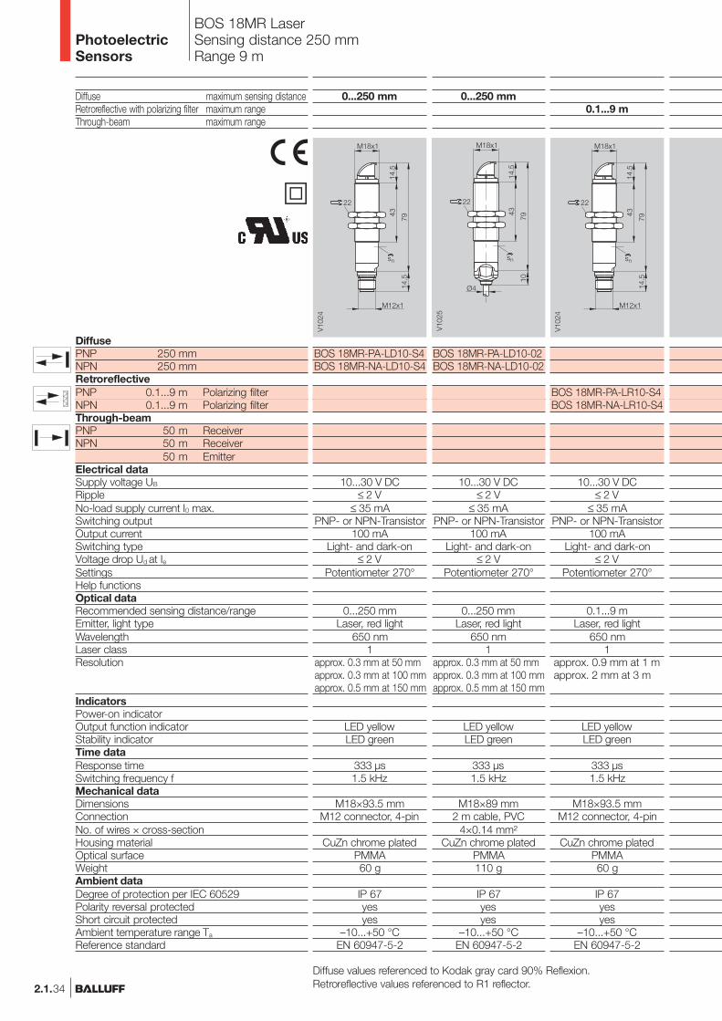
BOS 18MR LaserSensing distance 250 mmRange 9 m
Diffuse maximum sensing distanceRetroreflective with polarizing filter maximum rangeThrough-beam maximum range
DiffusePNP 250 mmNPN 250 mmRetroreflectivePNP 0.1...9 m Polarizing filterNPN 0.1...9 m Polarizing filterThrough-beamPNP 50 m ReceiverNPN 50 m Receiver
50 m EmitterElectrical dataSupply voltage UB
RippleNo-load supply current I0 max.Switching outputOutput currentSwitching typeVoltage drop Ud at IeSettingsHelp functionsOptical dataRecommended sensing distance/rangeEmitter, light typeWavelengthLaser classResolution
IndicatorsPower-on indicatorOutput function indicatorStability indicatorTime dataResponse timeSwitching frequency fMechanical dataDimensionsConnectionNo. of wires × cross-sectionHousing materialOptical surfaceWeightAmbient dataDegree of protection per IEC 60529Polarity reversal protectedShort circuit protectedAmbient temperature range Ta
Reference standard
0...250 mm
BOS 18MR-PA-LD10-S4BOS 18MR-NA-LD10-S4
10...30 V DC≤ 2 V
≤ 35 mAPNP- or NPN-Transistor
100 mALight- and dark-on
≤ 2 VPotentiometer 270°
0...250 mmLaser, red light
650 nm1
approx. 0.3 mm at 50 mmapprox. 0.3 mm at 100 mmapprox. 0.5 mm at 150 mm
LED yellowLED green
333 µs1.5 kHz
M18×93.5 mmM12 connector, 4-pin
CuZn chrome platedPMMA60 g
IP 67yesyes
–10...+50 °CEN 60947-5-2
0.1...9 m
BOS 18MR-PA-LR10-S4BOS 18MR-NA-LR10-S4
10...30 V DC≤ 2 V
≤ 35 mAPNP- or NPN-Transistor
100 mALight- and dark-on
≤ 2 VPotentiometer 270°
0.1...9 mLaser, red light
650 nm1
approx. 0.9 mm at 1 mapprox. 2 mm at 3 m
LED yellowLED green
333 µs1.5 kHz
M18×93.5 mmM12 connector, 4-pin
CuZn chrome platedPMMA60 g
IP 67yesyes
–10...+50 °CEN 60947-5-2
0...250 mm
BOS 18MR-PA-LD10-02BOS 18MR-NA-LD10-02
10...30 V DC≤ 2 V
≤ 35 mAPNP- or NPN-Transistor
100 mALight- and dark-on
≤ 2 VPotentiometer 270°
0...250 mmLaser, red light
650 nm1
approx. 0.3 mm at 50 mmapprox. 0.3 mm at 100 mmapprox. 0.5 mm at 150 mm
LED yellowLED green
333 µs1.5 kHz
M18×89 mm2 m cable, PVC
4×0.14 mm²CuZn chrome plated
PMMA110 g
IP 67yesyes
–10...+50 °CEN 60947-5-2
Diffuse values referenced to Kodak gray card 90% Reflexion.Retroreflective values referenced to R1 reflector.
PhotoelectricSensors
�
2.1.35
2.1
Connectors ...page 5.2 ...
Photoelectricsensorsaccessoriespage 2.3.2 ...
2.3
5
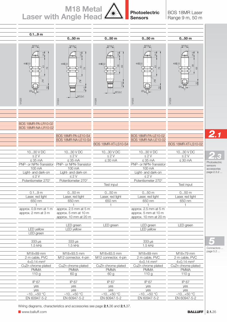
BOS 18MR LaserRange 9 m, 50 m
0.1...9 m
BOS 18MR-PA-LR10-02BOS 18MR-NA-LR10-02
10...30 V DC≤ 2 V
≤ 35 mAPNP- or NPN-Transistor
100 mALight- and dark-on
≤ 2 VPotentiometer 270°
0.1...9 mLaser, red light
650 nm1
approx. 0.9 mm at 1 mapprox. 2 mm at 3 m
LED yellowLED green
333 µs1.5 kHz
M18×89 mm2 m cable, PVC
4×0.14 mm²CuZn chrome plated
PMMA110 g
IP 67yesyes
–10...+50 °CEN 60947-5-2
M18 MetalLaser with Angle Head
0...50 m
BOS 18MR-PA-LE10-S4BOS 18MR-NA-LE10-S4
10...30 V DC≤ 2 V
≤ 35 mAPNP- or NPN-Transistor
100 mALight- and dark-on
≤ 2 VPotentiometer 270°
0...50 mLaser, red light
650 nm1
approx. 2.5 mm at 5 mapprox. 5 mm at 10 mapprox. 10 mm at 20 m
LED greenLED yellow
333 µs1.5 kHz
M18×93.5 mmM12 connector, 4-pin
CuZn chrome platedPMMA60 g
IP 67yesyes
–10...+50 °CEN 60947-5-2
0...50 m
BOS 18MR-PA-LE10-02BOS 18MR-NA-LE10-02
10...30 V DC≤ 2 V
≤ 35 mAPNP- or NPN-Transistor
100 mALight- and dark-on
≤ 2 VPotentiometer 270°
0...50 mLaser, red light
650 nm1
approx. 2.5 mm at 5 mapprox. 5 mm at 10 mapprox. 10 mm at 20 m
LED greenLED yellow
333 µs1.5 kHz
M18×89 mm2 m cable, PVC
4×0.14 mm²CuZn chrome plated
PMMA110 g
IP 67yesyes
–10...+50 °CEN 60947-5-2
0...50 m
BOS 18MR-XT-LS10-S4
10...30 V DC≤ 2 V
≤ 30 mA
Test input
0...50 mLaser, red light
650 nm1
LED green
M18×83.5 mmM12 connector, 4-pin
CuZn chrome platedPMMA60 g
IP 67yesyes
–10...+50 °CEN 60947-5-2
0...50 m
BOS 18MR-XT-LS10-02
10...30 V DC≤ 2 V
≤ 30 mA
Test input
0...50 mLaser, red light
650 nm1
LED green
M18×79 mm2 m cable, PVC
4×0.14 mm²CuZn chrome plated
PMMA110 g
IP 67yesyes
–10...+50 °CEN 60947-5-2
Wiring diagrams, characteristics and accessories see page 2.1.36 and 2.1.37.
www.balluff.com
PhotoelectricSensors
2.1.36
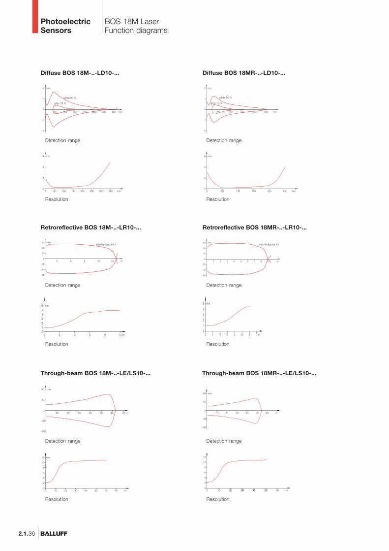
BOS 18M LaserFunction diagrams
Detection range
Resolution
Diffuse BOS 18MR-..-LD10-...
Retroreflective BOS 18MR-..-LR10-...
Through-beam BOS 18MR-..-LE/LS10-...
Detection range
Resolution
Detection range
Resolution
white 90 %
gray 18 %
with Reflector R1
Detection range
Resolution
Diffuse BOS 18M-..-LD10-...
white 90 %
gray 18 %
Retroreflective BOS 18M-..-LR10-...
Detection range
Resolution
with Reflector R1
Through-beam BOS 18M-..-LE/LS10-...
Detection range
Resolution
PhotoelectricSensors

2.1.37
2.1
Photoelectricsensorsaccessoriespage 2.3.2 ...
2.3
BOS 18M LaserConnectionAccessories
M18 MetalLaser with angle head
BN
BK
WH
BU
+UB
0 V
1
4
2
3
+UB
0 VTest+
Test–
BN
BK
WH
BU
+UB
0 VTest+
Test–
BN
BK
WH
BU
+UB
0 V
Wiring diagrams
BOS 18...PA...
BOS 18...NA...
BOS 18...XT...
Mounting clampBOS 18,0-KB-1
Cover nutBOS 18-SM-1for BOS 18M Laser
Air shieldBOS 18-LT-1for BOS 18M Laser
Mounting bracketBES 18-HW-1
ConnectorBKS-_ 19/BKS-_ 20
ReflectorBOS R-1
Recommended accessoriesplease order separately
www.balluff.com
Connectors ...page 5.2 ...
5
PhotoelectricSensors
2.1.38
Laser through-beam range
PNP 50 m Receiver50 m Emitter
Electrical dataSupply voltage UB
No-load supply current I0 max.Switching outputOutput currentSwitching typeVoltage drop Ud at IeSettingsOptical dataEmitter, light typeWavelengthLaser classLight spot diameterIndicatorsOutput function indicatorStability indicatorTime dataResponse timeSwitching frequency fMechanical dataConnectionHousing materialOptical surfaceWeightAmbient dataDegree of protection per IEC 60529Polarity reversal protectedShort circuit protectedAmbient temperature range Ta
Ambient light rejection
Connector orientation
Wiring diagrams
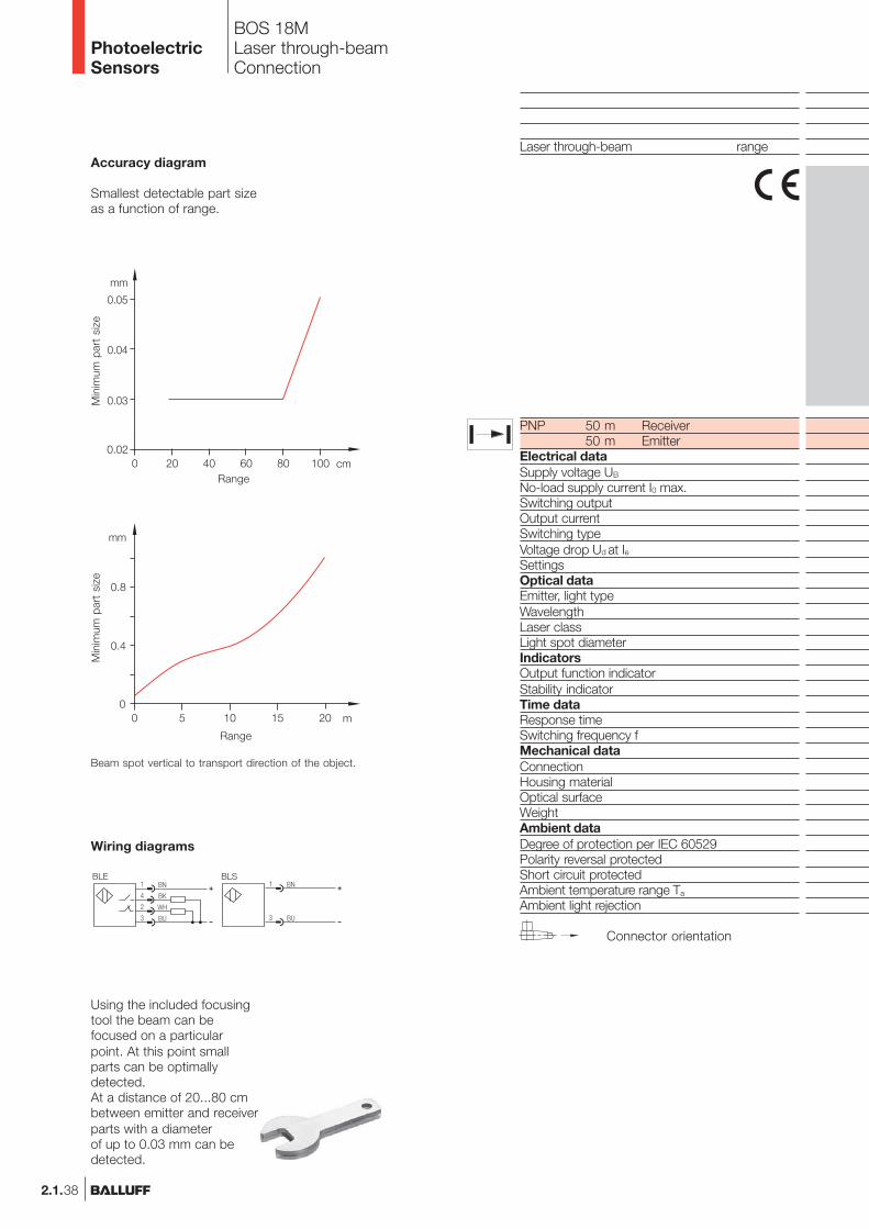
Accuracy diagram
Smallest detectable part sizeas a function of range.
Beam spot vertical to transport direction of the object.
Range
Min
imum
par
t si
ze
Range
Min
imum
par
t si
ze
Using the included focusingtool the beam can befocused on a particularpoint. At this point smallparts can be optimallydetected.At a distance of 20...80 cmbetween emitter and receiverparts with a diameterof up to 0.03 mm can bedetected.
BOS 18MLaser through-beamConnection
PhotoelectricSensors

2.1.39
2.1
Photoelectricsensorsaccessoriespage 2.3.2 ...
2.3
BOS 18MLaser Through-beamRange 50 m
0...50 m
BLE 18MR-BA-1LT-S4-C
10...30 V DC≤ 15 mA
PNP-Transistor200 mA
Light-/dark-on (complementary)≤ 2.5 V
18-turn potentiometer
LED yellowLED green/red
≤ 0.08 ms6 kHz
M12 connector, 4-pinNickel plated brass
Glass50 g
IP 65yesyes
–15...+55 °C2 kLux
0...50 m
BLE 18M-BA-1LT-S4-C
10...30 V DC≤ 15 mA
PNP-Transistor200 mA
Light-/dark-on (complementary)≤ 2.5 V
18-turn potentiometer
LED yellowLED green/red
≤ 0.08 ms6 kHz
M12 connector, 4-pinNickel plated brass
Glass45 g
IP 65yesyes
–15...+55 °C2 kLux
0...50 m
BLS 18M-XX-1LT-S4-C
10...30 V DC≤ 10 mA
Laser, red light650 nm
2focusable
M12 connector, 4-pinNickel plated brass
Glass45 g
IP 65yesyes
–15...+55 °C2 kLux
0...50 m
BLS 18MR-XX-1LT-S4-C
10...30 V DC≤ 10 mA
Laser, red light650 nm
2focusable
M12 connector, 4-pinNickel plated brass
Glass50 g
IP 65yesyes
–15...+55 °C2 kLux
Recommendedaccessoriesplease order separately
Mounting clampBOS 18,0-KB-1
ConnectorBKS-_ 19/BKS-_ 20
M18 MetalLaser
www.balluff.com
Connectors ...page 5.2 ...
5
PhotoelectricSensors
2.1.40
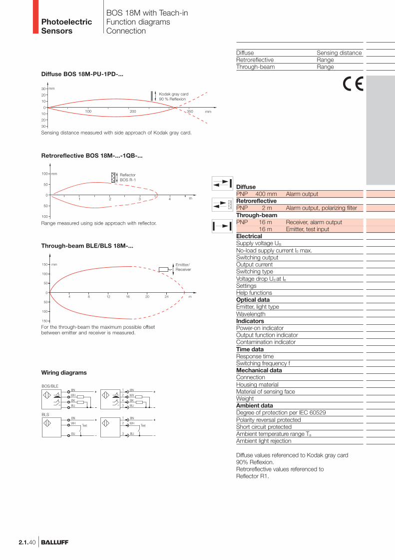
BOS 18M with Teach-inFunction diagramsConnection
Diffuse Sensing distanceRetroreflective RangeThrough-beam Range
DiffusePNP 400 mm Alarm outputRetroreflectivePNP 2 m Alarm output, polarizing filterThrough-beamPNP 16 m Receiver, alarm output
16 m Emitter, test inputElectricalSupply voltage UB
No-load supply current I0 max.Switching outputOutput currentSwitching typeVoltage drop Ud at IeSettingsHelp functionsOptical dataEmitter, light typeWavelengthIndicatorsPower-on indicatorOutput function indicatorContamination indicatorTime dataResponse timeSwitching frequency fMechanical dataConnectionHousing materialMaterial of sensing faceWeightAmbient dataDegree of protection per IEC 60529Polarity reversal protectedShort circuit protectedAmbient temperature range Ta
Ambient light rejection
Wiring diagrams
Diffuse BOS 18M-PU-1PD-...
Kodak gray card90 % Reflexion
Sensing distance measured with side approach of Kodak gray card.
Retroreflective BOS 18M-...-1QB-...
ReflectorBOS R-1
Range measured using side approach with reflector.
Through-beam BLE/BLS 18M-...
For the through-beam the maximum possible offsetbetween emitter and receiver is measured.
Emitter/Receiver
Diffuse values referenced to Kodak gray card90% Reflexion.Retroreflective values referenced toReflector R1.
PhotoelectricSensors
2.1.41
2.1
Photoelectricsensorsaccessoriespage 2.3.2 ...
2.3
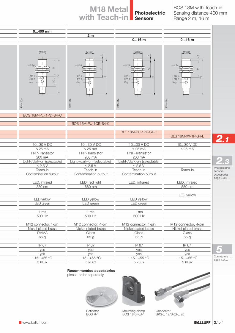
BOS 18M with Teach-inSensing distance 400 mmRange 2 m, 16 m
M18 Metalwith Teach-in
2 m
BOS 18M-PU-1QB-S4-C
10...30 V DC≤ 25 mA
PNP-Transistor200 mA
Light-/dark-on (selectable)≤ 2.5 VTeach-in
Contamination output
LED, red light660 nm
LED yellowLED green
1 ms500 Hz
M12 connector, 4-pinNickel plated brass
Glass65 g
IP 67yesyes
–15...+55 °C5 kLux
0...400 mm
BOS 18M-PU-1PD-S4-C
10...30 V DC≤ 25 mA
PNP-Transistor200 mA
Light-/dark-on (selectable)≤ 2.5 VTeach-in
Contamination output
LED, infrared880 nm
LED yellowLED green
1 ms500 Hz
M12 connector, 4-pinNickel plated brass
PMMA65 g
IP 67yesyes
–15...+55 °C5 kLux
Key Key
0...16 m
BLE 18M-PU-1PP-S4-C
10...30 V DC≤ 25 mA
PNP-Transistor200 mA
Light-/dark-on (selectable)≤ 2.5 VTeach-in
Contamination output
LED, infrared
LED yellowLED green
1 ms500 Hz
M12 connector, 4-pinNickel plated brass
Glass65 g
IP 67yesyes
–15...+55 °C5 kLux
0...16 m
BLS 18M-XX-1P-S4-L
10...30 V DC≤ 25 mA
Teach-in
LED, infrared880 nm
LED yellow
M12 connector, 4-pinNickel plated brass
Glass65 g
IP 67yesyes
–15...+55 °C5 kLux
Recommended accessoriesplease order separately
Mounting clampBOS 18,0-KB-1
ReflectorBOS R-1
Key Key
ConnectorBKS-_ 19/BKS-_ 20
www.balluff.com
Connectors ...page 5.2 ...
5
PhotoelectricSensors
2.1.42
Diffuse Sensing distanceRetroreflective RangeThrough-beam Range
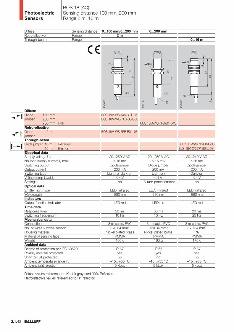
DiffuseDiode- 100 mmjumper 200 mm
200 mm PotiRetroreflectiveDiode- 2 mjumperThrough-beamDiode jumper 16 m Receiver
16 m EmitterElectrical dataSupply voltage UB
No-load supply current I0 max.Switching outputOutput currentSwitching typeVoltage drop Ud at IeSettingsOptical dataEmitter, light typeWavelengthIndicatorsOutput function indicatorTime dataResponse timeSwitching frequency fMechanical dataConnectionNo. of wires × cross-sectionHousing materialMaterial of sensing faceWeightAmbient dataDegree of protection per IEC 60529Polarity reversal protectedShort circuit protectedAmbient temperature range Ta
Ambient light rejection
0...100 mm/0...200 mm2 m
BOS 18M-WS-7XA-B0-L-03BOS 18M-WS-7XB-B0-L-03
BOS 18M-WS-7RB-B0-L-03
20...250 V AC≤ 15 mA
Diode jumper200 mA
Light- or dark-on≤ 4 Vno
LED, infrared880 nm
LED red
50 ms10 Hz
3 m cable, PVC3×0.34 mm²
Nickel plated brassPMMA160 g
IP 67yesno
–15...+55 °C5 kLux
0...16 m
BLE 18K-WS-7P-B0-L-03BLS 18K-XX-7P-B0-L-03
20...240 V AC≤ 15 mA
Diode jumper200 mADark-on
≤ 4 Vno
LED, infrared880 nm
LED red
20 ms25 Hz
3 m cable, PVC3×0.34 mm²
PAPMMA175 g
IP 67yesno
–15...+55 °C5 kLux
0...200 mm
BOS 18M-WS-7PB-B1-L-03
20...250 V AC≤ 15 mA
Diode jumper200 mALight-on
≤ 4 V16-turn potentiometer
LED, infrared880 nm
LED red
50 ms10 Hz
3 m cable, PVC3×0.34 mm²
Nickel plated brassPMMA160 g
IP 67yesno
–15...+55 °C5 kLux
Diffuse values referenced to Kodak gray card 90% Reflexion.Retroreflective values referenced to R1 reflector.
BOS 18 (AC)Sensing distance 100 mm, 200 mmRange 2 m, 16 m
PhotoelectricSensors
2.1.43
2.1
Photoelectricsensorsaccessoriespage 2.3.2 ...
2.3
BOS 18 (AC)ConnectionAccessories
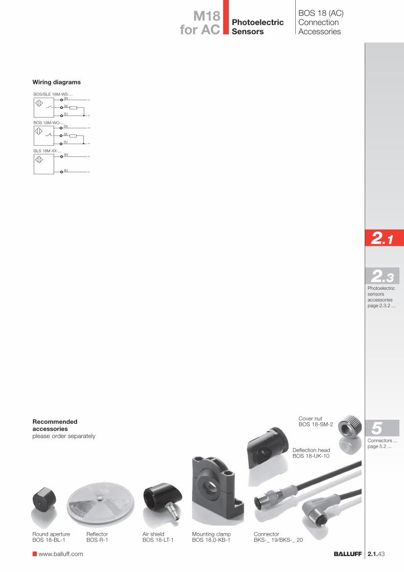
Mounting clampBOS 18,0-KB-1
Round apertureBOS 18-BL-1
ReflectorBOS R-1
Cover nutBOS 18-SM-2
Air shieldBOS 18-LT-1
Recommendedaccessoriesplease order separately
Deflection headBOS 18-UK-10
ConnectorBKS-_ 19/BKS-_ 20
M18for AC
Wiring diagrams
www.balluff.com
Connectors ...page 5.2 ...
5
PhotoelectricSensors
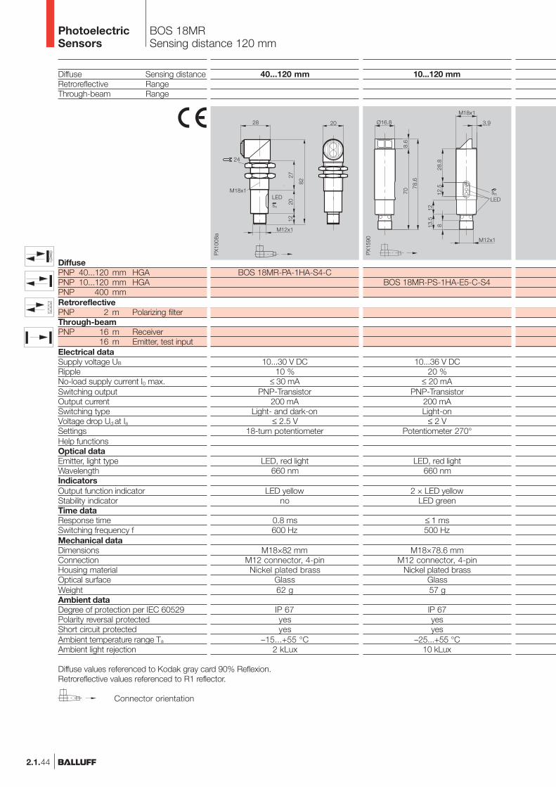
BOS 18MRSensing distance 120 mm
Diffuse Sensing distanceRetroreflective RangeThrough-beam Range
DiffusePNP 40...120 mm HGAPNP 10...120 mm HGAPNP 400 mmRetroreflectivePNP 2 m Polarizing filterThrough-beamPNP 16 m Receiver
16 m Emitter, test inputElectrical dataSupply voltage UB
RippleNo-load supply current I0 max.Switching outputOutput currentSwitching typeVoltage drop Ud at IeSettingsHelp functionsOptical dataEmitter, light typeWavelengthIndicatorsOutput function indicatorStability indicatorTime dataResponse timeSwitching frequency fMechanical dataDimensionsConnectionHousing materialOptical surfaceWeightAmbient dataDegree of protection per IEC 60529Polarity reversal protectedShort circuit protectedAmbient temperature range Ta
Ambient light rejection
Diffuse values referenced to Kodak gray card 90% Reflexion.Retroreflective values referenced to R1 reflector.
10...120 mm
BOS 18MR-PS-1HA-E5-C-S4
10...36 V DC20 %
≤ 20 mAPNP-Transistor
200 mALight-on
≤ 2 VPotentiometer 270°
LED, red light660 nm
2 × LED yellowLED green
≤ 1 ms500 Hz
M18×78.6 mmM12 connector, 4-pin
Nickel plated brassGlass57 g
IP 67yesyes
–25...+55 °C10 kLux
40...120 mm
BOS 18MR-PA-1HA-S4-C
10...30 V DC10 %
≤ 30 mAPNP-Transistor
200 mALight- and dark-on
≤ 2.5 V18-turn potentiometer
LED, red light660 nm
LED yellowno
0.8 ms600 Hz
M18×82 mmM12 connector, 4-pinNickel plated brass
Glass62 g
IP 67yesyes
–15...+55 °C2 kLux
Connector orientation
2.1.44
PhotoelectricSensors
2 m
BOS 18MR-PS-1QB-E5-C-S4
10...36 V DC20 %
≤ 20 mAPNP-Transistor
200 mADark-on
≤ 2 VPotentiometer 270°
LED, red light660 nm
2 × LED yellowLED green
≤ 0.5 ms1 kHz
M18×78.6 mmM12 connector, 4-pin
Nickel plated brassGlass56 g
IP 67yesyes
–25...+55 °C10 kLux
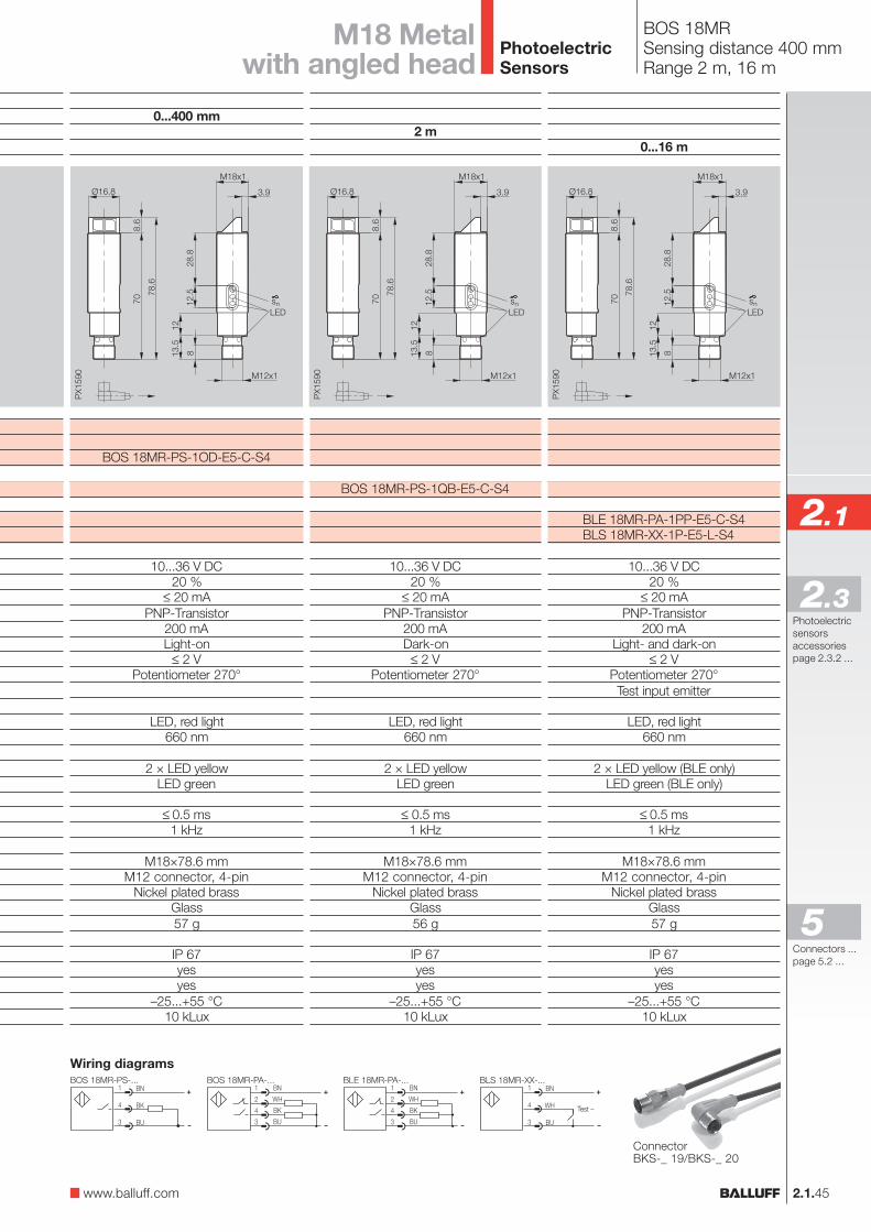
BOS 18MRSensing distance 400 mmRange 2 m, 16 m
0...400 mm
BOS 18MR-PS-1OD-E5-C-S4
10...36 V DC20 %
≤ 20 mAPNP-Transistor
200 mALight-on
≤ 2 VPotentiometer 270°
LED, red light660 nm
2 × LED yellowLED green
≤ 0.5 ms1 kHz
M18×78.6 mmM12 connector, 4-pin
Nickel plated brassGlass57 g
IP 67yesyes
–25...+55 °C10 kLux
0...16 m
BLE 18MR-PA-1PP-E5-C-S4BLS 18MR-XX-1P-E5-L-S4
10...36 V DC20 %
≤ 20 mAPNP-Transistor
200 mALight- and dark-on
≤ 2 VPotentiometer 270°Test input emitter
LED, red light660 nm
2 × LED yellow (BLE only)LED green (BLE only)
≤ 0.5 ms1 kHz
M18×78.6 mmM12 connector, 4-pin
Nickel plated brassGlass57 g
IP 67yesyes
–25...+55 °C10 kLux
M18 Metalwith angled head
Wiring diagrams
ConnectorBKS-_ 19/BKS-_ 20
2.1.45
2.1
Photoelectricsensorsaccessoriespage 2.3.2 ...
2.3
www.balluff.com
Connectors ...page 5.2 ...
5
PhotoelectricSensors
2.1.46
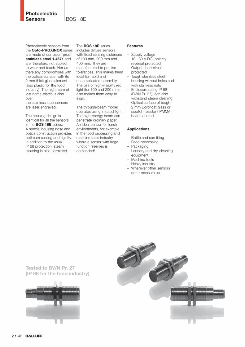
The BOS 18E seriesincludes diffuse sensorswith fixed sensing distancesof 100 mm, 200 mm and400 mm. They aremanufactured to precisetolerances. This makes themideal for rapid anduncomplicated assembly.The use of high-visibility redlight (for 100 and 200 mm)also makes them easy toalign.
The through-beam modeloperates using infrared light.The high-energy beam canpenetrate ordinary paper.An ideal sensor for harshenvironments, for examplein the food processing andmachine tools industry,where a sensor with largefunction reserves isdemanded!
Features
– Supply voltage10...30 V DC, polarityreversal protected
– Output short circuitprotected
– Tough stainless steelhousing without holes andwith stainless nuts
– Enclosure rating IP 68(BWN Pr. 27), can alsowithstand steam cleaning
– Optical surface of tough2 mm Borofloat glass orscratch-resistant PMMA,bead secured.
Applications
– Bottle and can filling– Food processing– Packaging– Laundry and dry-cleaning
equipment– Machine tools– Heavy industry– Wherever other sensors
don’t measure up
Photoelectric sensors fromthe Opto-PROXINOX seriesare made of corrosion-proofstainless steel 1.4571 andare, therefore, not subjectto wear and teach. Nor arethere any compromises withthe optical surface, with its2 mm thick glass element(also plastic for the foodindustry). The nightmare oflost name-plates is alsoover:the stainless steel sensorsare laser engraved.
The housing design isidentical for all the sensorsin the BOS 18E series.A special housing nose andoptics construction providesoptimum sealing and rigidity.In addition to the usualIP 68 protection, steamcleaning is also permitted.
BOS 18EPhotoelectricSensors
Tested to BWN Pr. 27(IP 68 for the food industry)
2.1.47
2.1
Photoelectricsensorsaccessoriespage 2.3.2 ...
2.3
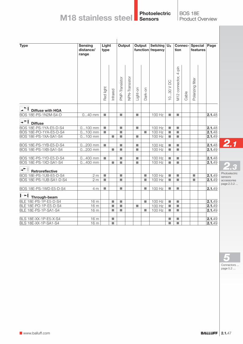
BOS 18EProduct Overview
Type
Diffuse with HGABOS 18E-PS-1N2M-S4-D
DiffuseBOS 18E-PS-1YA-E5-D-S4BOS 18E-PO-1YA-E5-D-S4BOS 18E-PS-1XA-SA1-S4
BOS 18E-PS-1YB-E5-D-S4BOS 18E-PS-1XB-SA1-S4
BOS 18E-PS-1YD-E5-D-S4BOS 18E-PS-1XD-SA1-S4
RetroreflectiveBOS 18E-PS-1UB-E5-D-S4BOS 18E-PS-1UB-SA1-D-S4
BOS 18E-PS-1WD-E5-D-S4
Through-beamBLE 18E-PS-1P-E5-D-S4BLE 18E-PO-1P-E5-D-S4BLE 18E-PS-1P-SA1-S4
BLS 18E-XX-1P-E5-X-S4BLS 18E-XX-1P-SA1-S4
OutputLighttype
Sensingdistance/range
0...40 mm
0...100 mm0...100 mm0...100 mm
0...200 mm0...200 mm
0...400 mm0...400 mm
2 m2 m
4 m
16 m16 m16 m
16 m16 m
Connec-tion
100 Hz
100 Hz100 Hz100 Hz
100 Hz100 Hz
100 Hz100 Hz
100 Hz100 Hz
100 Hz
100 Hz100 Hz100 Hz
Outputfunction
Page
2.1.48
2.1.482.1.482.1.49
2.1.482.1.49
2.1.482.1.49
2.1.492.1.49
2.1.49
2.1.492.1.492.1.49
2.1.492.1.49
Specialfeatures
Red
ligh
t
Infra
red
M12
con
nect
or, 4
-pin
Cab
le
10...
30 V
DC
Pol
ariz
ing
filte
r
NP
N-T
rans
isto
r
PN
P-T
rans
isto
r
Ligh
t-on
Dar
k-on
UBSwitchingfrequency
M18 stainless steel
www.balluff.com
Connectors ...page 5.2 ...
5
PhotoelectricSensors
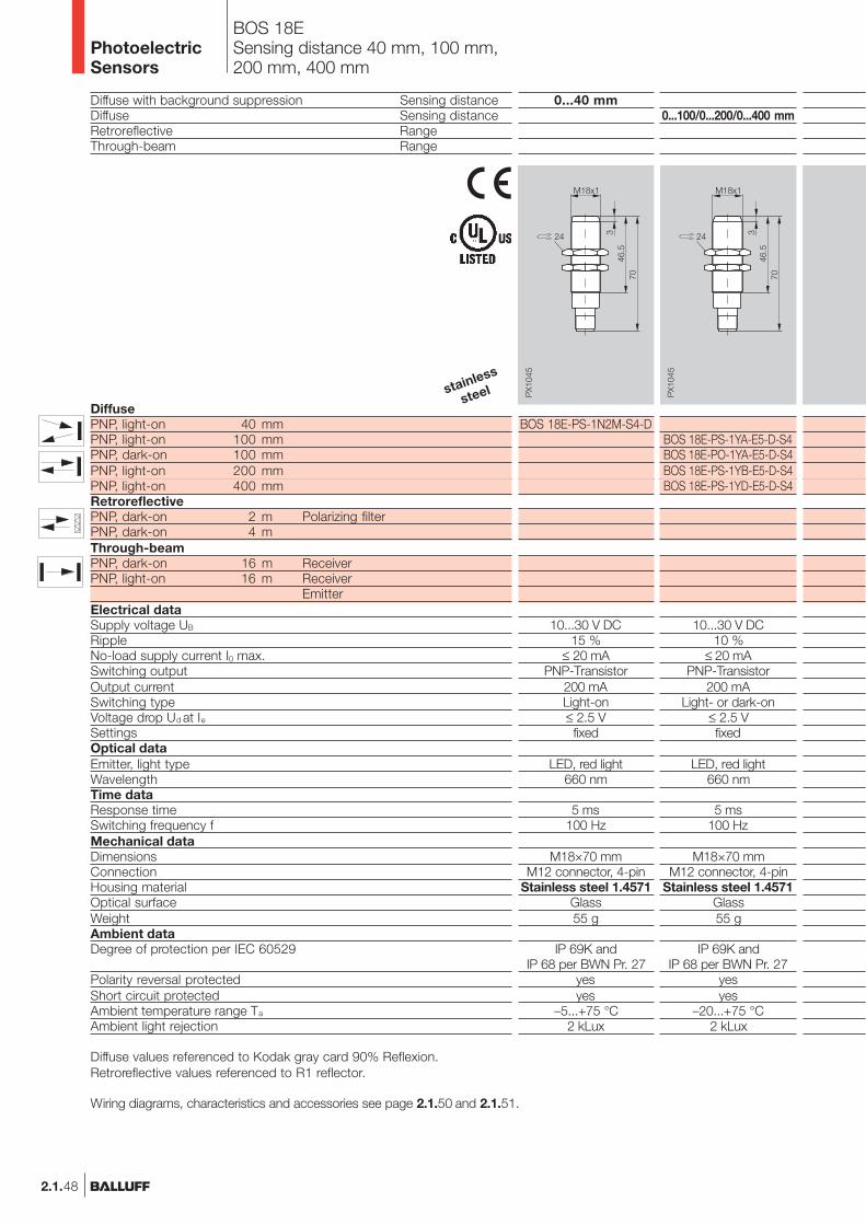
2.1.48
BOS 18ESensing distance 40 mm, 100 mm,200 mm, 400 mm
Diffuse with background suppression Sensing distanceDiffuse Sensing distanceRetroreflective RangeThrough-beam Range
DiffusePNP, light-on 40 mmPNP, light-on 100 mmPNP, dark-on 100 mmPNP, light-on 200 mmPNP, light-on 400 mmRetroreflectivePNP, dark-on 2 m Polarizing filterPNP, dark-on 4 mThrough-beamPNP, dark-on 16 m ReceiverPNP, light-on 16 m Receiver
EmitterElectrical dataSupply voltage UB
RippleNo-load supply current I0 max.Switching outputOutput currentSwitching typeVoltage drop Ud at IeSettingsOptical dataEmitter, light typeWavelengthTime dataResponse timeSwitching frequency fMechanical dataDimensionsConnectionHousing materialOptical surfaceWeightAmbient dataDegree of protection per IEC 60529
Polarity reversal protectedShort circuit protectedAmbient temperature range Ta
Ambient light rejection
0...40 mm
BOS 18E-PS-1N2M-S4-D
10...30 V DC15 %
≤ 20 mAPNP-Transistor
200 mALight-on≤ 2.5 Vfixed
LED, red light660 nm
5 ms100 Hz
M18×70 mmM12 connector, 4-pin
Stainless steel 1.4571Glass55 g
IP 69K andIP 68 per BWN Pr. 27
yesyes
–5...+75 °C2 kLux
Diffuse values referenced to Kodak gray card 90% Reflexion.Retroreflective values referenced to R1 reflector.
Wiring diagrams, characteristics and accessories see page 2.1.50 and 2.1.51.
0...100/0...200/0...400 mm
BOS 18E-PS-1YA-E5-D-S4BOS 18E-PO-1YA-E5-D-S4BOS 18E-PS-1YB-E5-D-S4BOS 18E-PS-1YD-E5-D-S4
10...30 V DC10 %
≤ 20 mAPNP-Transistor
200 mALight- or dark-on
≤ 2.5 Vfixed
LED, red light660 nm
5 ms100 Hz
M18×70 mmM12 connector, 4-pin
Stainless steel 1.4571Glass55 g
IP 69K andIP 68 per BWN Pr. 27
yesyes
–20...+75 °C2 kLux
PhotoelectricSensors
stainless
steel
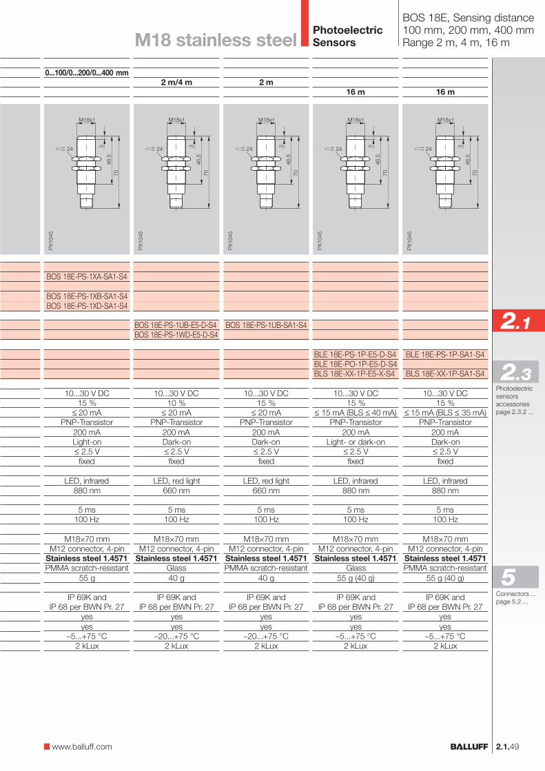
2.1.49
2.1
Photoelectricsensorsaccessoriespage 2.3.2 ...
2.3
BOS 18E, Sensing distance100 mm, 200 mm, 400 mmRange 2 m, 4 m, 16 mM18 stainless steel
2 m
BOS 18E-PS-1UB-SA1-S4
10...30 V DC15 %
≤ 20 mAPNP-Transistor
200 mADark-on≤ 2.5 Vfixed
LED, red light660 nm
5 ms100 Hz
M18×70 mmM12 connector, 4-pin
Stainless steel 1.4571PMMA scratch-resistant
40 g
IP 69K andIP 68 per BWN Pr. 27
yesyes
–20...+75 °C2 kLux
2 m/4 m
BOS 18E-PS-1UB-E5-D-S4BOS 18E-PS-1WD-E5-D-S4
10...30 V DC10 %
≤ 20 mAPNP-Transistor
200 mADark-on≤ 2.5 Vfixed
LED, red light660 nm
5 ms100 Hz
M18×70 mmM12 connector, 4-pin
Stainless steel 1.4571Glass40 g
IP 69K andIP 68 per BWN Pr. 27
yesyes
–20...+75 °C2 kLux
16 m
BLE 18E-PS-1P-SA1-S4
BLS 18E-XX-1P-SA1-S4
10...30 V DC15 %
≤ 15 mA (BLS ≤ 35 mA)PNP-Transistor
200 mADark-on≤ 2.5 Vfixed
LED, infrared880 nm
5 ms100 Hz
M18×70 mmM12 connector, 4-pin
Stainless steel 1.4571PMMA scratch-resistant
55 g (40 g)
IP 69K andIP 68 per BWN Pr. 27
yesyes
–5...+75 °C2 kLux
16 m
BLE 18E-PS-1P-E5-D-S4BLE 18E-PO-1P-E5-D-S4BLS 18E-XX-1P-E5-X-S4
10...30 V DC15 %
≤ 15 mA (BLS ≤ 40 mA)PNP-Transistor
200 mALight- or dark-on
≤ 2.5 Vfixed
LED, infrared880 nm
5 ms100 Hz
M18×70 mmM12 connector, 4-pin
Stainless steel 1.4571Glass
55 g (40 g)
IP 69K andIP 68 per BWN Pr. 27
yesyes
–5...+75 °C2 kLux
0...100/0...200/0...400 mm
BOS 18E-PS-1XA-SA1-S4
BOS 18E-PS-1XB-SA1-S4BOS 18E-PS-1XD-SA1-S4
10...30 V DC15 %
≤ 20 mAPNP-Transistor
200 mALight-on≤ 2.5 Vfixed
LED, infrared880 nm
5 ms100 Hz
M18×70 mmM12 connector, 4-pin
Stainless steel 1.4571PMMA scratch-resistant
55 g
IP 69K andIP 68 per BWN Pr. 27
yesyes
–5...+75 °C2 kLux
www.balluff.com
Connectors ...page 5.2 ...
5
PhotoelectricSensors
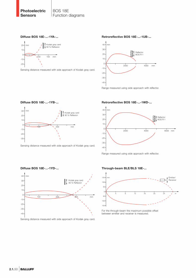
2.1.50
BOS 18EFunction diagrams
Diffuse BOS 18E-...-1YA-...
Sensing distance measured with side approach of Kodak gray card.
Kodak gray card90 % Reflexion
Diffuse BOS 18E-...-1YB-...
Sensing distance measured with side approach of Kodak gray card.
Kodak gray card90 % Reflexion
Diffuse BOS 18E-...-1YD-...
Kodak gray card90 % Reflexion
Sensing distance measured with side approach of Kodak gray card.
Through-beam BLE/BLS 18E-...
For the through-beam the maximum possible offsetbetween emitter and receiver is measured.
Emitter/Receiver
Retroreflective BOS 18E-...-1WD-...
ReflectorBOS R-1
Range measured using side approach with reflector.
Retroreflective BOS 18E-...-1UB-...
ReflectorBOS R-1
Range measured using side approach with reflector.
PhotoelectricSensors
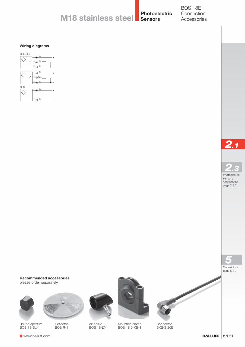
2.1.51
2.1
Photoelectricsensorsaccessoriespage 2.3.2 ...
2.3
Wiring diagrams
Recommended accessoriesplease order separately
ConnectorBKS-S 20E
Mounting clampBOS 18,0-KB-1
Round apertureBOS 18-BL-1
ReflectorBOS R-1
Air shieldBOS 18-LT-1
BOS 18EConnectionAccessoriesM18 stainless steel
www.balluff.com
Connectors ...page 5.2 ...
5
PhotoelectricSensors
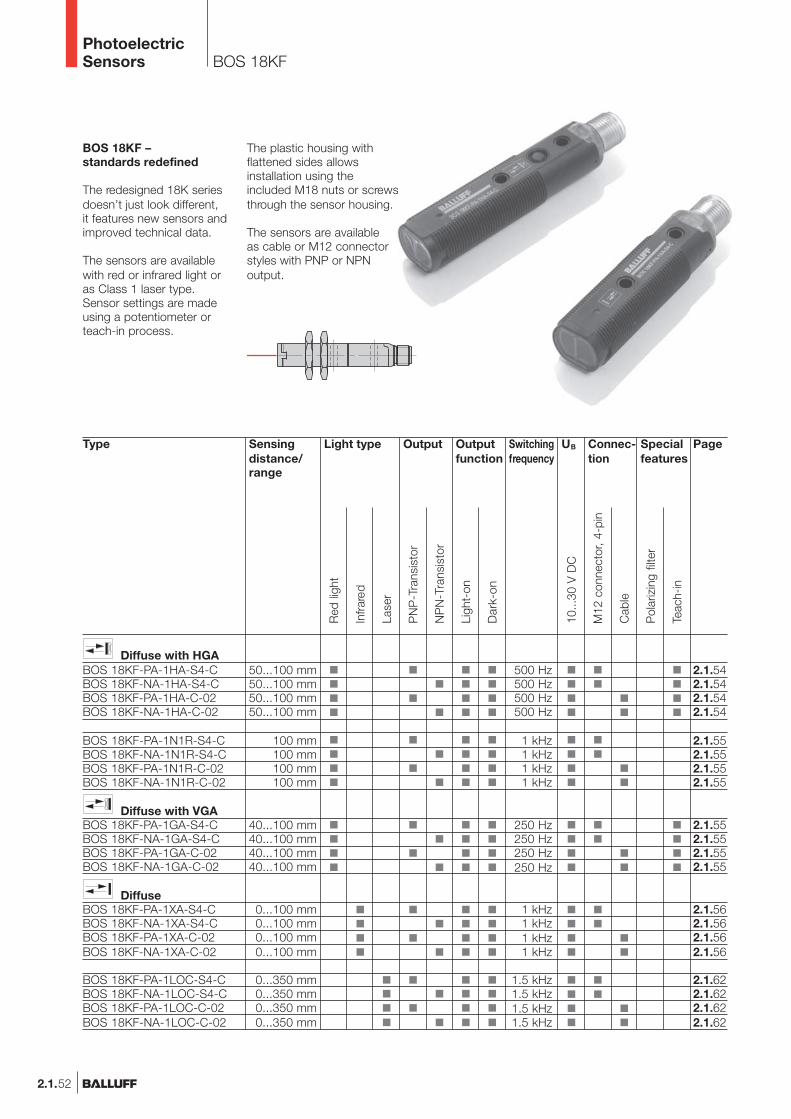
2.1.52
BOS 18KF
BOS 18KF –standards redefined
The redesigned 18K seriesdoesn’t just look different,it features new sensors andimproved technical data.
The sensors are availablewith red or infrared light oras Class 1 laser type.Sensor settings are madeusing a potentiometer orteach-in process.
The plastic housing withflattened sides allowsinstallation using theincluded M18 nuts or screwsthrough the sensor housing.
The sensors are availableas cable or M12 connectorstyles with PNP or NPNoutput.
Type
Diffuse with HGABOS 18KF-PA-1HA-S4-CBOS 18KF-NA-1HA-S4-CBOS 18KF-PA-1HA-C-02BOS 18KF-NA-1HA-C-02
BOS 18KF-PA-1N1R-S4-CBOS 18KF-NA-1N1R-S4-CBOS 18KF-PA-1N1R-C-02BOS 18KF-NA-1N1R-C-02
Diffuse with VGABOS 18KF-PA-1GA-S4-CBOS 18KF-NA-1GA-S4-CBOS 18KF-PA-1GA-C-02BOS 18KF-NA-1GA-C-02
DiffuseBOS 18KF-PA-1XA-S4-CBOS 18KF-NA-1XA-S4-CBOS 18KF-PA-1XA-C-02BOS 18KF-NA-1XA-C-02
BOS 18KF-PA-1LOC-S4-CBOS 18KF-NA-1LOC-S4-CBOS 18KF-PA-1LOC-C-02BOS 18KF-NA-1LOC-C-02
OutputLight typeSensingdistance/range
50...100 mm50...100 mm50...100 mm50...100 mm
100 mm100 mm100 mm100 mm
40...100 mm40...100 mm40...100 mm40...100 mm
0...100 mm0...100 mm0...100 mm0...100 mm
0...350 mm0...350 mm0...350 mm0...350 mm
Connec-tion
500 Hz500 Hz500 Hz500 Hz
1 kHz1 kHz1 kHz1 kHz
250 Hz250 Hz250 Hz250 Hz
1 kHz1 kHz1 kHz1 kHz
1.5 kHz1.5 kHz1.5 kHz1.5 kHz
Outputfunction
Page
2.1.542.1.542.1.542.1.54
2.1.552.1.552.1.552.1.55
2.1.552.1.552.1.552.1.55
2.1.562.1.562.1.562.1.56
2.1.622.1.622.1.622.1.62
Specialfeatures
Red
ligh
t
Infra
red
M12
con
nect
or, 4
-pin
Cab
le
10...
30 V
DC
Pol
ariz
ing
filte
r
NP
N-T
rans
isto
r
PN
P-T
rans
isto
r
Ligh
t-on
Dar
k-on
UBSwitchingfrequency
Lase
r
Teac
h-in
PhotoelectricSensors
2.1.53
2.1
Photoelectricsensorsaccessoriespage 2.3.2 ...
2.3
BOS 18KFProduct overviewM18 plastic
Type
DiffuseBOS 18KF-PA-1PD-S4-CBOS 18KF-NA-1PD-S4-CBOS 18KF-PA-1PD-C-02BOS 18KF-NA-1PD-C-02
BOS 18KF-PA-1PE-S4-CBOS 18KF-NA-1PE-S4-CBOS 18KF-PA-1PE-C-02BOS 18KF-NA-1PE-C-02
RetroreflectiveBOS 18KF-PA-1TB-S4-CBOS 18KF-NA-1TB-S4-CBOS 18KF-PA-1TB-C-02BOS 18KF-NA-1TB-C-02
BOS 18KF-PA-1QD-S4-CBOS 18KF-NA-1QD-S4-CBOS 18KF-PA-1QD-C-02BOS 18KF-NA-1QD-C-02
BOS 18KF-PA-1RE-S4-CBOS 18KF-NA-1RE-S4-CBOS 18KF-PA-1RE-C-02BOS 18KF-NA-1RE-C-02
BOS 18KF-PA-1LQP-S4-CBOS 18KF-NA-1LQP-S4-CBOS 18KF-PA-1LQP-C-02BOS 18KF-NA-1LQP-C-02
Through-beamBLE 18KF-PA-1PP-S4-CBLE 18KF-NA-1PP-S4-CBLE 18KF-PA-1PP-C-02BLE 18KF-NA-1PP-C-02
BLE 18KF-PA-1LT-S4-CBLE 18KF-NA-1LT-S4-CBLE 18KF-PA-1LT-C-02BLE 18KF-NA-1LT-C-02
BLS 18KF-XX-1P-S4-LBLS 18KF-XX-1P-L-02
BLS 18KF-XX-1LT-S4-LBLS 18KF-XX-1LT-L-02
OutputLight typeSensingdistance/range
0...400 mm0...400 mm0...400 mm0...400 mm
0...700 mm0...700 mm0...700 mm0...700 mm
0.1...1.7 m0.1...1.7 m0.1...1.7 m0.1...1.7 m
0.1...4.5 m0.1...4.5 m0.1...4.5 m0.1...4.5 m
0.1...5 m0.1...5 m0.1...5 m0.1...5 m
0.1...16 m0.1...16 m0.1...16 m0.1...16 m
0...20 m0...20 m0...20 m0...20 m
0...60 m0...60 m0...60 m0...60 m
0...20 m0...20 m
0...60 m0...60 m
Connec-tion
1 kHz1 kHz1 kHz1 kHz
1 kHz1 kHz1 kHz1 kHz
1 kHz1 kHz1 kHz1 kHz
1 kHz1 kHz1 kHz1 kHz
1 kHz1 kHz1 kHz1 kHz
1.5 kHz1.5 kHz1.5 kHz1.5 kHz
250 Hz250 Hz250 Hz250 Hz
1.5 kHz1.5 kHz1.5 kHz1.5 kHz
Outputfunction
Page
2.1.572.1.572.1.572.1.57
2.1.572.1.572.1.572.1.57
2.1.582.1.582.1.582.1.58
2.1.592.1.592.1.592.1.59
2.1.592.1.592.1.592.1.59
2.1.632.1.632.1.632.1.63
2.1.602.1.602.1.612.1.61
2.1.642.1.642.1.652.1.65
2.1.602.1.61
2.1.642.1.65
Specialfeatures
Red
ligh
t
Infra
red
M12
con
nect
or, 4
-pin
Cab
le
10...
30 V
DC
Pol
ariz
ing
filte
r
NP
N-T
rans
isto
r
PN
P-T
rans
isto
r
Ligh
t-on
Dar
k-on
UBSwitchingfrequency
Lase
r
Gla
ss s
ensi
ng
www.balluff.com
Connectors ...page 5.2 ...
5
PhotoelectricSensors
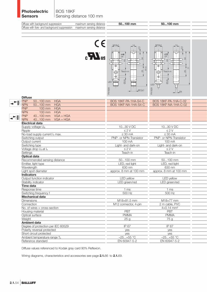
2.1.54
BOS 18KFSensing distance 100 mm
Diffuse with background suppression maximum sensing distanceDiffuse with fore- and background suppression maximum sensing distance
DiffusePNP 50...100 mm HGANPN 50...100 mm HGAPNP 100 mm HGANPN 100 mm HGAPNP 40...100 mm VGA + HGANPN 40...100 mm VGA + HGAElectrical dataSupply voltage UB
RippleNo-load supply current I0 max.Switching outputOutput currentSwitching typeVoltage drop Ud at IeSettingsOptical dataRecommended sensing distanceEmitter, light typeWavelengthLight spot diameterIndicatorsOutput function indicatorStability indicatorTime dataResponse timeSwitching frequency fMechanical dataDimensionsConnectionNo. of wires × cross-sectionHousing materialOptical surfaceWeightAmbient dataDegree of protection per IEC 60529Polarity reversal protectedShort circuit protectedAmbient temperature range Ta
Reference standard
50...100 mm
BOS 18KF-PA-1HA-S4-CBOS 18KF-NA-1HA-S4-C
10...30 V DC≤ 2 V
≤ 30 mAPNP- or NPN-Transistor
100 mALight- and dark-on
≤ 2 VTeach-in
50...100 mmLED, red light
630 nmapprox. 8 mm at 100 mm
LED yellowLED green/red
1 ms500 Hz
M18×81.5 mmM12 connector, 4-pin
PBTPMMA25 g
IP 67yesyes
–25...+55 °CEN 60947-5-2
50...100 mm
BOS 18KF-PA-1HA-C-02BOS 18KF-NA-1HA-C-02
10...30 V DC≤ 2 V
≤ 30 mAPNP- or NPN-Transistor
100 mALight- and dark-on
≤ 2 VTeach-in
50...100 mmLED, red light
630 nmapprox. 8 mm at 100 mm
LED yellowLED green/red
1 ms500 Hz
M18×77 mm2 m cable, PVC
4×0.14 mm²PBT
PMMA75 g
IP 67yesyes
–25...+55 °CEN 60947-5-2
Teach-in Teach-in
Diffuse values referenced to Kodak gray card 90% Reflexion.
Wiring diagrams, characteristics and accessories see page 2.1.66 to 2.1.69.
PhotoelectricSensors
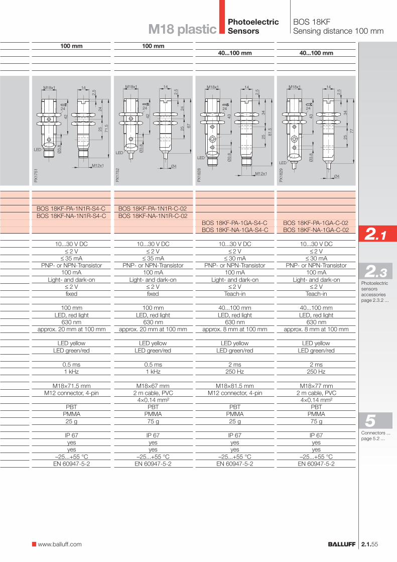
2.1.55
2.1
Photoelectricsensorsaccessoriespage 2.3.2 ...
2.3
BOS 18KFSensing distance 100 mmM18 plastic
40...100 mm
BOS 18KF-PA-1GA-S4-CBOS 18KF-NA-1GA-S4-C
10...30 V DC≤ 2 V
≤ 30 mAPNP- or NPN-Transistor
100 mALight- and dark-on
≤ 2 VTeach-in
40...100 mmLED, red light
630 nmapprox. 8 mm at 100 mm
LED yellowLED green/red
2 ms250 Hz
M18×81.5 mmM12 connector, 4-pin
PBTPMMA25 g
IP 67yesyes
–25...+55 °CEN 60947-5-2
40...100 mm
BOS 18KF-PA-1GA-C-02BOS 18KF-NA-1GA-C-02
10...30 V DC≤ 2 V
≤ 30 mAPNP- or NPN-Transistor
100 mALight- and dark-on
≤ 2 VTeach-in
40...100 mmLED, red light
630 nmapprox. 8 mm at 100 mm
LED yellowLED green/red
2 ms250 Hz
M18×77 mm2 m cable, PVC
4×0.14 mm²PBT
PMMA75 g
IP 67yesyes
–25...+55 °CEN 60947-5-2
100 mm
BOS 18KF-PA-1N1R-S4-CBOS 18KF-NA-1N1R-S4-C
10...30 V DC≤ 2 V
≤ 35 mAPNP- or NPN-Transistor
100 mALight- and dark-on
≤ 2 Vfixed
100 mmLED, red light
630 nmapprox. 20 mm at 100 mm
LED yellowLED green/red
0.5 ms1 kHz
M18×71.5 mmM12 connector, 4-pin
PBTPMMA25 g
IP 67yesyes
–25...+55 °CEN 60947-5-2
100 mm
BOS 18KF-PA-1N1R-C-02BOS 18KF-NA-1N1R-C-02
10...30 V DC≤ 2 V
≤ 35 mAPNP- or NPN-Transistor
100 mALight- and dark-on
≤ 2 Vfixed
100 mmLED, red light
630 nmapprox. 20 mm at 100 mm
LED yellowLED green/red
0.5 ms1 kHz
M18×67 mm2 m cable, PVC
4×0.14 mm²PBT
PMMA75 g
IP 67yesyes
–25...+55 °CEN 60947-5-2
www.balluff.com
Connectors ...page 5.2 ...
5
PhotoelectricSensors
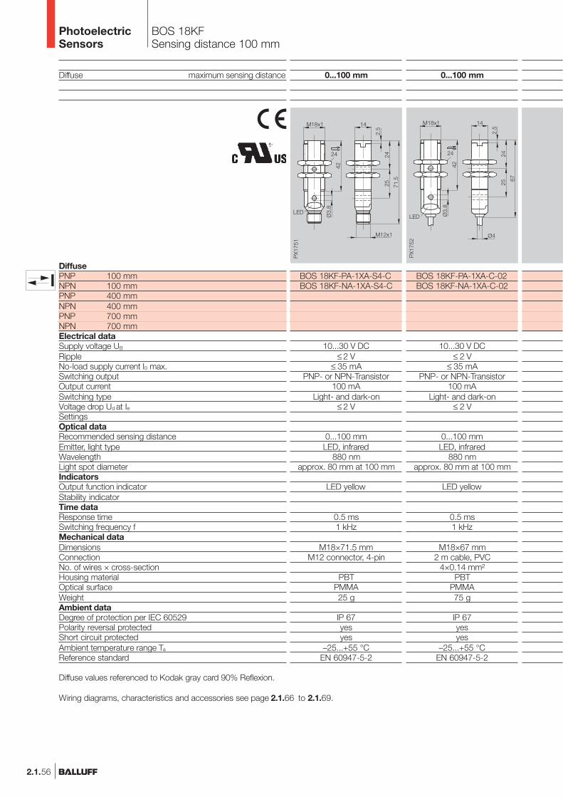
2.1.56
BOS 18KFSensing distance 100 mm
Diffuse maximum sensing distance
DiffusePNP 100 mmNPN 100 mmPNP 400 mmNPN 400 mmPNP 700 mmNPN 700 mmElectrical dataSupply voltage UB
RippleNo-load supply current I0 max.Switching outputOutput currentSwitching typeVoltage drop Ud at IeSettingsOptical dataRecommended sensing distanceEmitter, light typeWavelengthLight spot diameterIndicatorsOutput function indicatorStability indicatorTime dataResponse timeSwitching frequency fMechanical dataDimensionsConnectionNo. of wires × cross-sectionHousing materialOptical surfaceWeightAmbient dataDegree of protection per IEC 60529Polarity reversal protectedShort circuit protectedAmbient temperature range Ta
Reference standard
0...100 mm
BOS 18KF-PA-1XA-S4-CBOS 18KF-NA-1XA-S4-C
10...30 V DC≤ 2 V
≤ 35 mAPNP- or NPN-Transistor
100 mALight- and dark-on
≤ 2 V
0...100 mmLED, infrared
880 nmapprox. 80 mm at 100 mm
LED yellow
0.5 ms1 kHz
M18×71.5 mmM12 connector, 4-pin
PBTPMMA25 g
IP 67yesyes
–25...+55 °CEN 60947-5-2
0...100 mm
BOS 18KF-PA-1XA-C-02BOS 18KF-NA-1XA-C-02
10...30 V DC≤ 2 V
≤ 35 mAPNP- or NPN-Transistor
100 mALight- and dark-on
≤ 2 V
0...100 mmLED, infrared
880 nmapprox. 80 mm at 100 mm
LED yellow
0.5 ms1 kHz
M18×67 mm2 m cable, PVC
4×0.14 mm²PBT
PMMA75 g
IP 67yesyes
–25...+55 °CEN 60947-5-2
Diffuse values referenced to Kodak gray card 90% Reflexion.
Wiring diagrams, characteristics and accessories see page 2.1.66 to 2.1.69.
PhotoelectricSensors
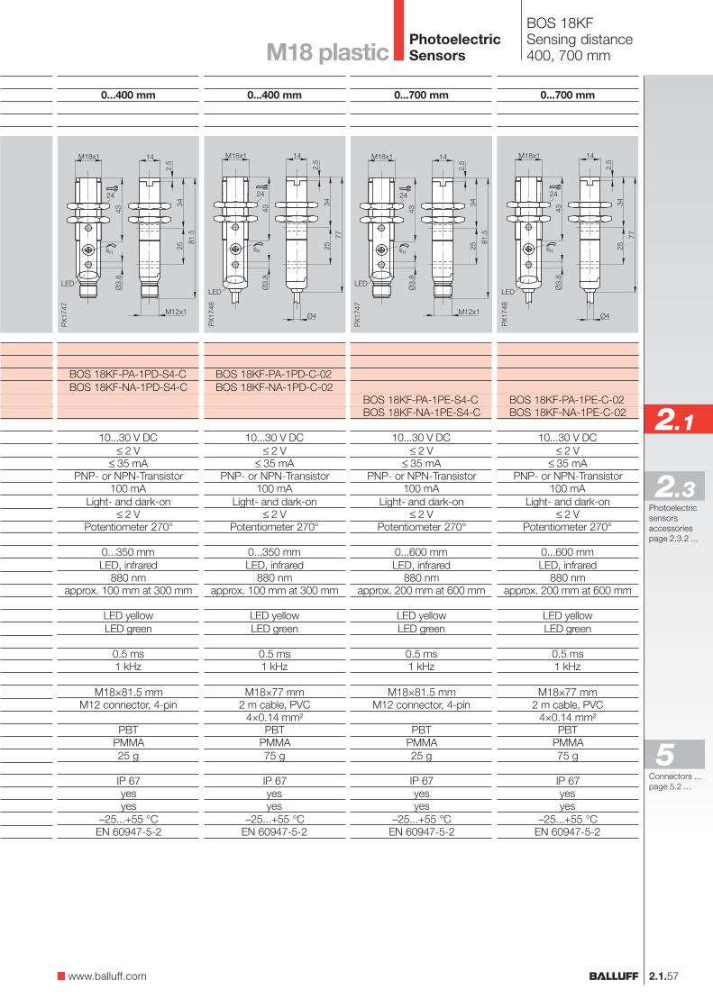
2.1.57
2.1
Photoelectricsensorsaccessoriespage 2.3.2 ...
2.3
BOS 18KFSensing distance400, 700 mmM18 plastic
0...700 mm
BOS 18KF-PA-1PE-C-02BOS 18KF-NA-1PE-C-02
10...30 V DC≤ 2 V
≤ 35 mAPNP- or NPN-Transistor
100 mALight- and dark-on
≤ 2 VPotentiometer 270°
0...600 mmLED, infrared
880 nmapprox. 200 mm at 600 mm
LED yellowLED green
0.5 ms1 kHz
M18×77 mm2 m cable, PVC
4×0.14 mm²PBT
PMMA75 g
IP 67yesyes
–25...+55 °CEN 60947-5-2
0...700 mm
BOS 18KF-PA-1PE-S4-CBOS 18KF-NA-1PE-S4-C
10...30 V DC≤ 2 V
≤ 35 mAPNP- or NPN-Transistor
100 mALight- and dark-on
≤ 2 VPotentiometer 270°
0...600 mmLED, infrared
880 nmapprox. 200 mm at 600 mm
LED yellowLED green
0.5 ms1 kHz
M18×81.5 mmM12 connector, 4-pin
PBTPMMA25 g
IP 67yesyes
–25...+55 °CEN 60947-5-2
0...400 mm
BOS 18KF-PA-1PD-C-02BOS 18KF-NA-1PD-C-02
10...30 V DC≤ 2 V
≤ 35 mAPNP- or NPN-Transistor
100 mALight- and dark-on
≤ 2 VPotentiometer 270°
0...350 mmLED, infrared
880 nmapprox. 100 mm at 300 mm
LED yellowLED green
0.5 ms1 kHz
M18×77 mm2 m cable, PVC
4×0.14 mm²PBT
PMMA75 g
IP 67yesyes
–25...+55 °CEN 60947-5-2
0...400 mm
BOS 18KF-PA-1PD-S4-CBOS 18KF-NA-1PD-S4-C
10...30 V DC≤ 2 V
≤ 35 mAPNP- or NPN-Transistor
100 mALight- and dark-on
≤ 2 VPotentiometer 270°
0...350 mmLED, infrared
880 nmapprox. 100 mm at 300 mm
LED yellowLED green
0.5 ms1 kHz
M18×81.5 mmM12 connector, 4-pin
PBTPMMA25 g
IP 67yesyes
–25...+55 °CEN 60947-5-2
www.balluff.com
Connectors ...page 5.2 ...
5
PhotoelectricSensors
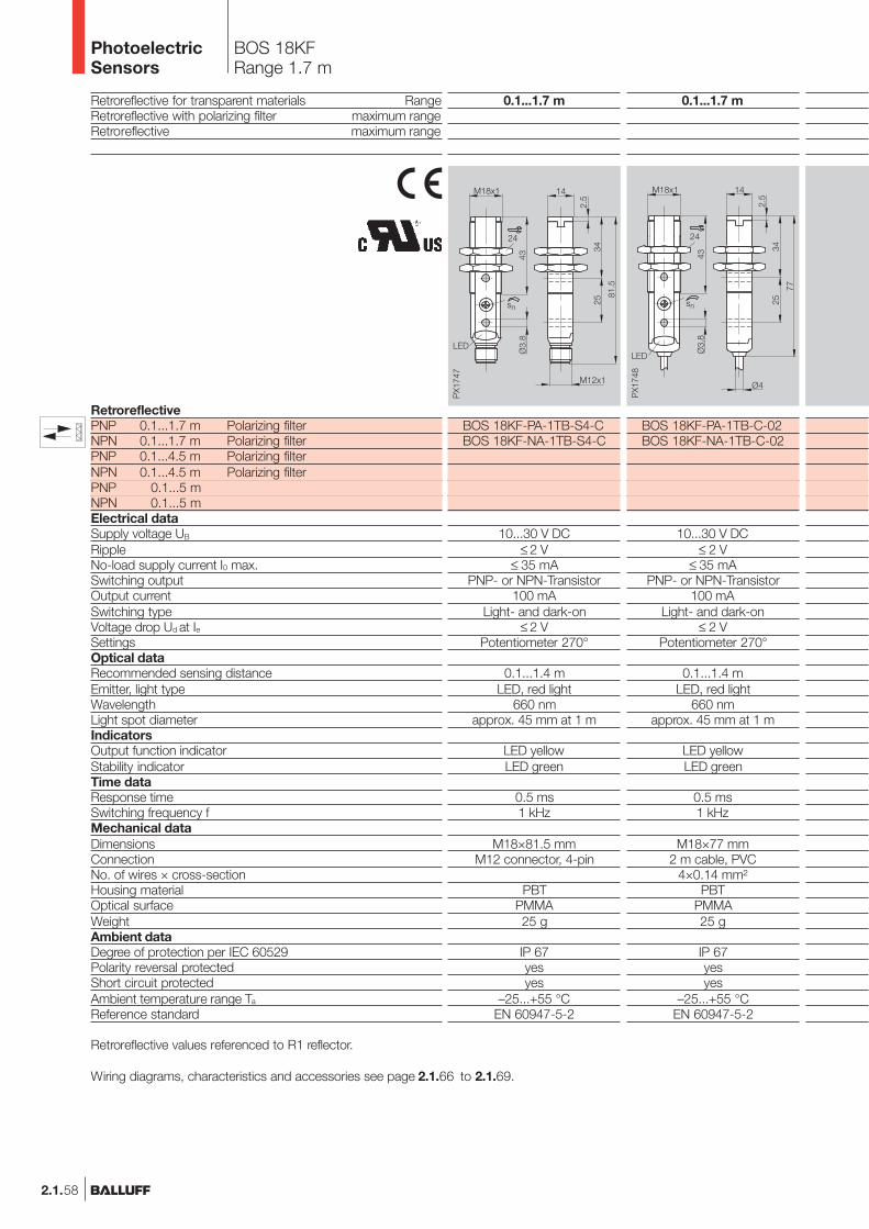
2.1.58
Retroreflective for transparent materials RangeRetroreflective with polarizing filter maximum rangeRetroreflective maximum range
RetroreflectivePNP 0.1...1.7 m Polarizing filterNPN 0.1...1.7 m Polarizing filterPNP 0.1...4.5 m Polarizing filterNPN 0.1...4.5 m Polarizing filterPNP 0.1...5 mNPN 0.1...5 mElectrical dataSupply voltage UB
RippleNo-load supply current I0 max.Switching outputOutput currentSwitching typeVoltage drop Ud at IeSettingsOptical dataRecommended sensing distanceEmitter, light typeWavelengthLight spot diameterIndicatorsOutput function indicatorStability indicatorTime dataResponse timeSwitching frequency fMechanical dataDimensionsConnectionNo. of wires × cross-sectionHousing materialOptical surfaceWeightAmbient dataDegree of protection per IEC 60529Polarity reversal protectedShort circuit protectedAmbient temperature range Ta
Reference standard
Retroreflective values referenced to R1 reflector.
Wiring diagrams, characteristics and accessories see page 2.1.66 to 2.1.69.
BOS 18KFRange 1.7 m
0.1...1.7 m
BOS 18KF-PA-1TB-S4-CBOS 18KF-NA-1TB-S4-C
10...30 V DC≤ 2 V
≤ 35 mAPNP- or NPN-Transistor
100 mALight- and dark-on
≤ 2 VPotentiometer 270°
0.1...1.4 mLED, red light
660 nmapprox. 45 mm at 1 m
LED yellowLED green
0.5 ms1 kHz
M18×81.5 mmM12 connector, 4-pin
PBTPMMA25 g
IP 67yesyes
–25...+55 °CEN 60947-5-2
0.1...1.7 m
BOS 18KF-PA-1TB-C-02BOS 18KF-NA-1TB-C-02
10...30 V DC≤ 2 V
≤ 35 mAPNP- or NPN-Transistor
100 mALight- and dark-on
≤ 2 VPotentiometer 270°
0.1...1.4 mLED, red light
660 nmapprox. 45 mm at 1 m
LED yellowLED green
0.5 ms1 kHz
M18×77 mm2 m cable, PVC
4×0.14 mm²PBT
PMMA25 g
IP 67yesyes
–25...+55 °CEN 60947-5-2
PhotoelectricSensors
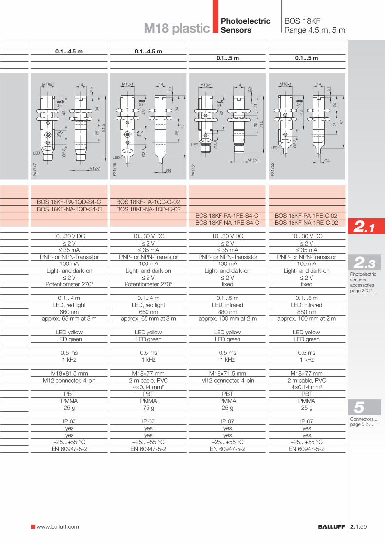
2.1.59
2.1
Photoelectricsensorsaccessoriespage 2.3.2 ...
2.3
0.1...4.5 m
BOS 18KF-PA-1QD-S4-CBOS 18KF-NA-1QD-S4-C
10...30 V DC≤ 2 V
≤ 35 mAPNP- or NPN-Transistor
100 mALight- and dark-on
≤ 2 VPotentiometer 270°
0.1...4 mLED, red light
660 nmapprox. 65 mm at 3 m
LED yellowLED green
0.5 ms1 kHz
M18×81.5 mmM12 connector, 4-pin
PBTPMMA25 g
IP 67yesyes
–25...+55 °CEN 60947-5-2
0.1...4.5 m
BOS 18KF-PA-1QD-C-02BOS 18KF-NA-1QD-C-02
10...30 V DC≤ 2 V
≤ 35 mAPNP- or NPN-Transistor
100 mALight- and dark-on
≤ 2 VPotentiometer 270°
0.1...4 mLED, red light
660 nmapprox. 65 mm at 3 m
LED yellowLED green
0.5 ms1 kHz
M18×77 mm2 m cable, PVC
4×0.14 mm²PBT
PMMA75 g
IP 67yesyes
–25...+55 °CEN 60947-5-2
BOS 18KFRange 4.5 m, 5 mM18 plastic
0.1...5 m
BOS 18KF-PA-1RE-S4-CBOS 18KF-NA-1RE-S4-C
10...30 V DC≤ 2 V
≤ 35 mAPNP- or NPN-Transistor
100 mALight- and dark-on
≤ 2 Vfixed
0.1...5 mLED, infrared
880 nmapprox. 100 mm at 2 m
LED yellowLED green
0.5 ms1 kHz
M18×71.5 mmM12 connector, 4-pin
PBTPMMA25 g
IP 67yesyes
–25...+55 °CEN 60947-5-2
0.1...5 m
BOS 18KF-PA-1RE-C-02BOS 18KF-NA-1RE-C-02
10...30 V DC≤ 2 V
≤ 35 mAPNP- or NPN-Transistor
100 mALight- and dark-on
≤ 2 Vfixed
0.1...5 mLED, infrared
880 nmapprox. 100 mm at 2 m
LED yellowLED green
0.5 ms1 kHz
M18×77 mm2 m cable, PVC
4×0.14 mm²PBT
PMMA25 g
IP 67yesyes
–25...+55 °CEN 60947-5-2
www.balluff.com
Connectors ...page 5.2 ...
5
PhotoelectricSensors
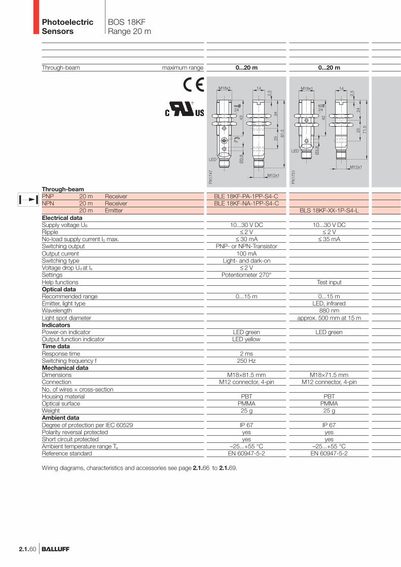
2.1.60
Through-beam maximum range
Through-beamPNP 20 m ReceiverNPN 20 m Receiver
20 m EmitterElectrical dataSupply voltage UB
RippleNo-load supply current I0 max.Switching outputOutput currentSwitching typeVoltage drop Ud at IeSettingsHelp functionsOptical dataRecommended rangeEmitter, light typeWavelengthLight spot diameterIndicatorsPower-on indicatorOutput function indicatorTime dataResponse timeSwitching frequency fMechanical dataDimensionsConnectionNo. of wires × cross-sectionHousing materialOptical surfaceWeightAmbient dataDegree of protection per IEC 60529Polarity reversal protectedShort circuit protectedAmbient temperature range Ta
Reference standard
0...20 m
BLE 18KF-PA-1PP-S4-CBLE 18KF-NA-1PP-S4-C
10...30 V DC≤ 2 V
≤ 30 mAPNP- or NPN-Transistor
100 mALight- and dark-on
≤ 2 VPotentiometer 270°
0...15 m
LED greenLED yellow
2 ms250 Hz
M18×81.5 mmM12 connector, 4-pin
PBTPMMA25 g
IP 67yesyes
–25...+55 °CEN 60947-5-2
0...20 m
BLS 18KF-XX-1P-S4-L
10...30 V DC≤ 2 V
≤ 35 mA
Test input
0...15 mLED, infrared
880 nmapprox. 500 mm at 15 m
LED green
M18×71.5 mmM12 connector, 4-pin
PBTPMMA25 g
IP 67yesyes
–25...+55 °CEN 60947-5-2
Wiring diagrams, characteristics and accessories see page 2.1.66 to 2.1.69.
BOS 18KFRange 20 m
PhotoelectricSensors

2.1.61
2.1
Photoelectricsensorsaccessoriespage 2.3.2 ...
2.3
0...20 m
BLS 18KF-XX-1P-L-02
10...30 V DC≤ 2 V
≤ 35 mA
Test input
0...15 mLED, infrared
880 nmapprox. 500 mm at 15 m
LED green
M18×67 mm2 m cable, PVC
4×0.14 mm²PBT
PMMA75 g
IP 67yesyes
–25...+55 °CEN 60947-5-2
0...20 m
BLE 18KF-PA-1PP-C-02BLE 18KF-NA-1PP-C-02
10...30 V DC≤ 2 V
≤ 30 mAPNP- or NPN-Transistor
100 mALight- and dark-on
≤ 2 VPotentiometer 270°
0...15 m
LED greenLED yellow
2 ms250 Hz
M18×77 mm2 m cable, PVC
4×0.14 mm²PBT
PMMA75 g
IP 67yesyes
–25...+55 °CEN 60947-5-2
BOS 18KFRange 20 mM18 plastic
www.balluff.com
Connectors ...page 5.2 ...
5
PhotoelectricSensors

2.1.62
Diffuse values referenced to Kodak gray card 90% Reflexion.Retroreflective values referenced to R1 reflector.
Wiring diagrams, characteristics and accessories see page 2.1.66 to 2.1.69.
Diffuse maximum sensing distanceRetroreflective with polarizing filter maximum range
DiffusePNP 350 mmNPN 350 mmRetroreflectivePNP 0.1...16 m Polarizing filterNPN 0.1...16 m Polarizing filterElectrical dataSupply voltage UB
RippleNo-load supply current I0 max.Switching outputOutput currentSwitching typeVoltage drop Ud at IeSettingsOptical dataRecommended sensing distance/rangeEmitter, light typeWavelengthLaser classResolution
IndicatorsPower-on indicatorOutput function indicatorTime dataResponse timeSwitching frequency fMechanical dataDimensionsConnectionNo. of wires × cross-sectionHousing materialOptical surfaceWeightAmbient dataDegree of protection per IEC 60529Polarity reversal protectedShort circuit protectedAmbient temperature range Ta
Reference standard
0...350 mm
BOS 18KF-PA-1LOC-S4-CBOS 18KF-NA-1LOC-S4-C
10...30 V DC≤ 2 V
≤ 35 mAPNP- or NPN-Transistor
100 mALight- and dark-on
≤ 2 VPotentiometer 270°
0...350 mmLaser, red light
650 nmClass 1
approx. 0.3 mm at 50 mmapprox. 0.3 mm at 100 mmapprox. 0.5 mm at 150 mm
LED greenLED yellow
333 µs1.5 kHz
M18×81.5 mmM12 connector, 4-pin
PBTPMMA25 g
IP 67yesyes
–10...+50 °CEN 60947-5-2
0...350 mm
BOS 18KF-PA-1LOC-C-02BOS 18KF-NA-1LOC-C-02
10...30 V DC≤ 2 V
≤ 35 mAPNP- or NPN-Transistor
100 mALight- and dark-on
≤ 2 VPotentiometer 270°
0...350 mmLaser, red light
650 nmClass 1
approx. 0.3 mm at 50 mmapprox. 0.3 mm at 100 mmapprox. 0.5 mm at 150 mm
LED greenLED yellow
333 µs1.5 kHz
M18×77 mm2 m cable, PVC
4×0.14 mm²PBT
PMMA75 g
IP 67yesyes
–10...+50 °CEN 60947-5-2
BOS 18KF LaserSensing distance 350 mm
PhotoelectricSensors
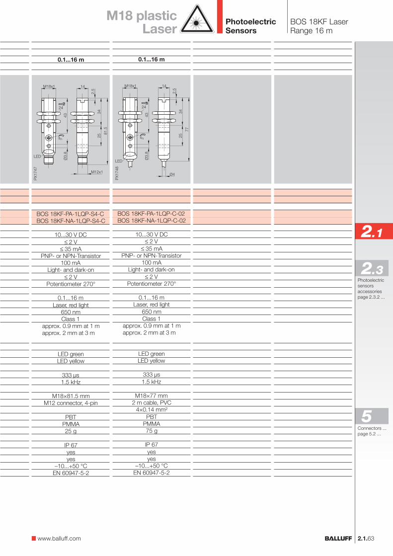
2.1.63
2.1
Photoelectricsensorsaccessoriespage 2.3.2 ...
2.3
0.1...16 m
BOS 18KF-PA-1LQP-S4-CBOS 18KF-NA-1LQP-S4-C
10...30 V DC≤ 2 V
≤ 35 mAPNP- or NPN-Transistor
100 mALight- and dark-on
≤ 2 VPotentiometer 270°
0.1...16 mLaser, red light
650 nmClass 1
approx. 0.9 mm at 1 mapprox. 2 mm at 3 m
LED greenLED yellow
333 µs1.5 kHz
M18×81.5 mmM12 connector, 4-pin
PBTPMMA25 g
IP 67yesyes
–10...+50 °CEN 60947-5-2
0.1...16 m
BOS 18KF-PA-1LQP-C-02BOS 18KF-NA-1LQP-C-02
10...30 V DC≤ 2 V
≤ 35 mAPNP- or NPN-Transistor
100 mALight- and dark-on
≤ 2 VPotentiometer 270°
0.1...16 mLaser, red light
650 nmClass 1
approx. 0.9 mm at 1 mapprox. 2 mm at 3 m
LED greenLED yellow
333 µs1.5 kHz
M18×77 mm2 m cable, PVC
4×0.14 mm²PBT
PMMA75 g
IP 67yesyes
–10...+50 °CEN 60947-5-2
BOS 18KF LaserRange 16 m
M18 plasticLaser
www.balluff.com
Connectors ...page 5.2 ...
5
PhotoelectricSensors
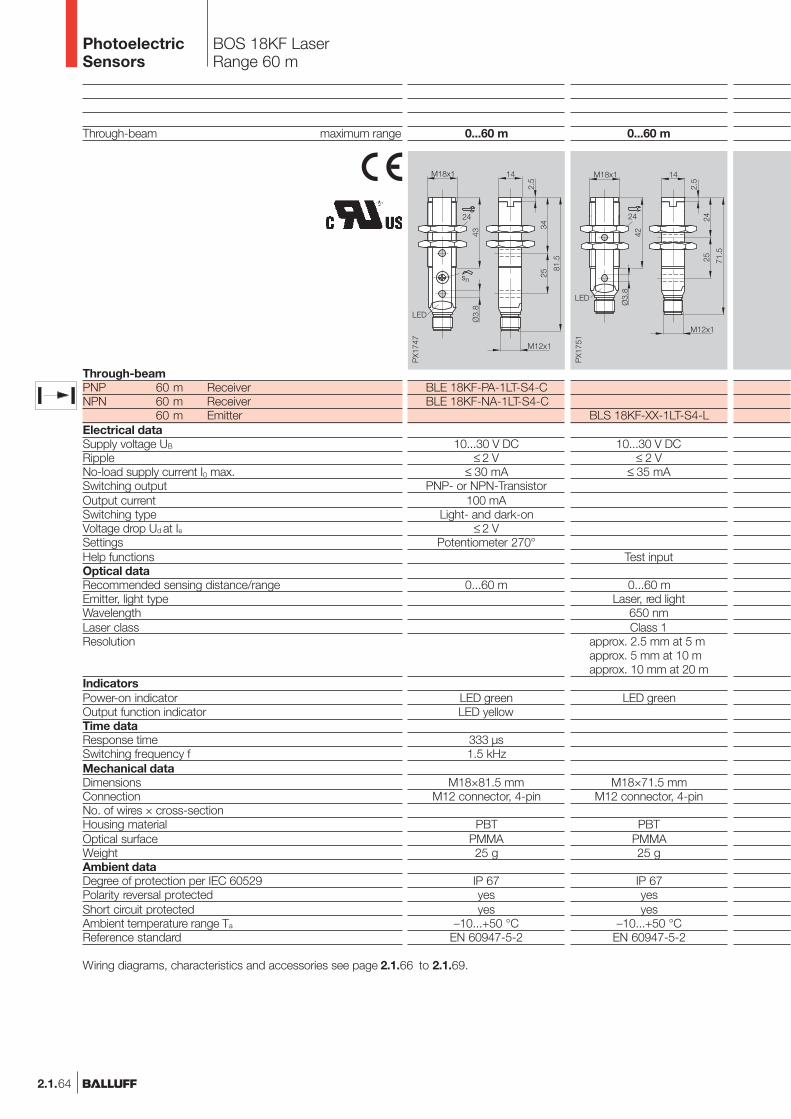
2.1.64
Through-beam maximum range
Through-beamPNP 60 m ReceiverNPN 60 m Receiver
60 m EmitterElectrical dataSupply voltage UB
RippleNo-load supply current I0 max.Switching outputOutput currentSwitching typeVoltage drop Ud at IeSettingsHelp functionsOptical dataRecommended sensing distance/rangeEmitter, light typeWavelengthLaser classResolution
IndicatorsPower-on indicatorOutput function indicatorTime dataResponse timeSwitching frequency fMechanical dataDimensionsConnectionNo. of wires × cross-sectionHousing materialOptical surfaceWeightAmbient dataDegree of protection per IEC 60529Polarity reversal protectedShort circuit protectedAmbient temperature range Ta
Reference standard
0...60 m
BLS 18KF-XX-1LT-S4-L
10...30 V DC≤ 2 V
≤ 35 mA
Test input
0...60 mLaser, red light
650 nmClass 1
approx. 2.5 mm at 5 mapprox. 5 mm at 10 mapprox. 10 mm at 20 m
LED green
M18×71.5 mmM12 connector, 4-pin
PBTPMMA25 g
IP 67yesyes
–10...+50 °CEN 60947-5-2
0...60 m
BLE 18KF-PA-1LT-S4-CBLE 18KF-NA-1LT-S4-C
10...30 V DC≤ 2 V
≤ 30 mAPNP- or NPN-Transistor
100 mALight- and dark-on
≤ 2 VPotentiometer 270°
0...60 m
LED greenLED yellow
333 µs1.5 kHz
M18×81.5 mmM12 connector, 4-pin
PBTPMMA25 g
IP 67yesyes
–10...+50 °CEN 60947-5-2
Wiring diagrams, characteristics and accessories see page 2.1.66 to 2.1.69.
BOS 18KF LaserRange 60 m
PhotoelectricSensors
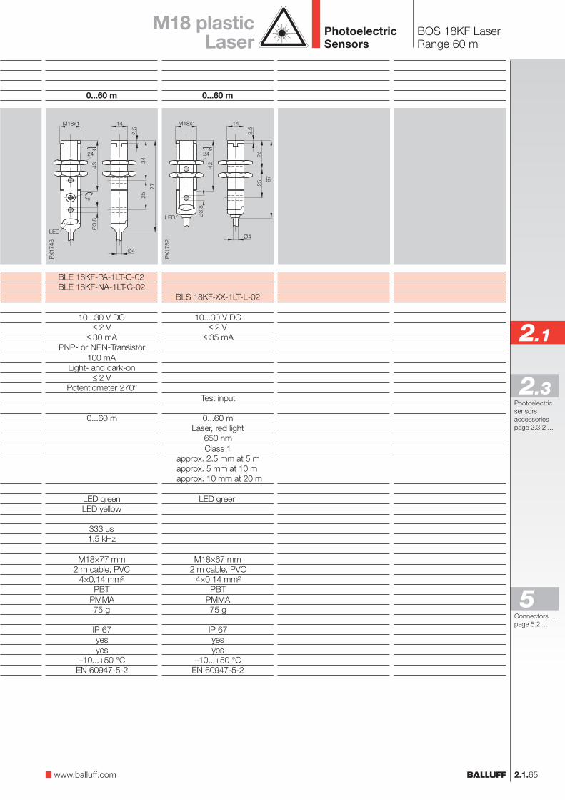
2.1.65
2.1
Photoelectricsensorsaccessoriespage 2.3.2 ...
2.3
0...60 m
BLS 18KF-XX-1LT-L-02
10...30 V DC≤ 2 V
≤ 35 mA
Test input
0...60 mLaser, red light
650 nmClass 1
approx. 2.5 mm at 5 mapprox. 5 mm at 10 mapprox. 10 mm at 20 m
LED green
M18×67 mm2 m cable, PVC
4×0.14 mm²PBT
PMMA75 g
IP 67yesyes
–10...+50 °CEN 60947-5-2
0...60 m
BLE 18KF-PA-1LT-C-02BLE 18KF-NA-1LT-C-02
10...30 V DC≤ 2 V
≤ 30 mAPNP- or NPN-Transistor
100 mALight- and dark-on
≤ 2 VPotentiometer 270°
0...60 m
LED greenLED yellow
333 µs1.5 kHz
M18×77 mm2 m cable, PVC
4×0.14 mm²PBT
PMMA75 g
IP 67yesyes
–10...+50 °CEN 60947-5-2
BOS 18KF LaserRange 60 m
M18 plasticLaser
www.balluff.com
Connectors ...page 5.2 ...
5
PhotoelectricSensors
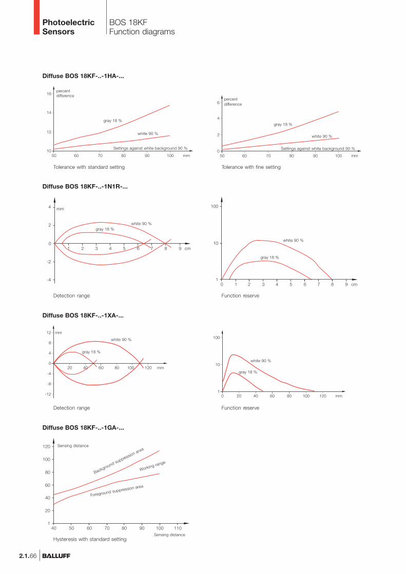
2.1.66
BOS 18KFFunction diagrams
Tolerance with standard setting
Diffuse BOS 18KF-..-1HA-...
Tolerance with fine setting
percentdifference
Settings against white background 90 %
white 90 %
gray 18 %
percentdifference
Settings against white background 90 %
white 90 %
gray 18 %
Diffuse BOS 18KF-..-1N1R-...
Detection range Function reserve
white 90 %gray 18 %
white 90 %
gray 18 %
Diffuse BOS 18KF-..-1XA-...
Detection range Function reserve
white 90 %
gray 18 %
white 90 %
gray 18 %
Diffuse BOS 18KF-..-1GA-...
Hysteresis with standard setting
Sensing distance
Sensing distance
Working range
Background suppression area
Foreground suppression area
PhotoelectricSensors
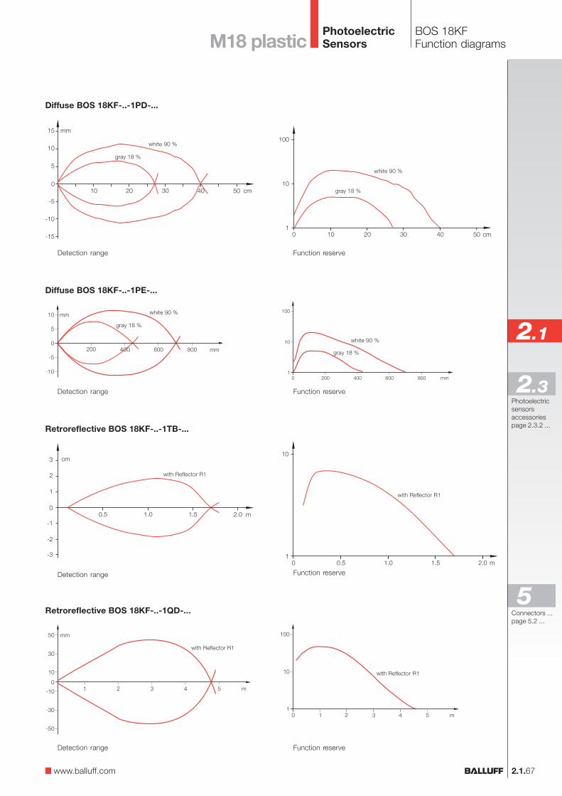
2.1.67
2.1
Photoelectricsensorsaccessoriespage 2.3.2 ...
2.3
BOS 18KFFunction diagramsM18 plastic
www.balluff.com
Detection range Function reserve
Diffuse BOS 18KF-..-1PD-...
white 90 %
gray 18 %
white 90 %
gray 18 %
Function reserve
Diffuse BOS 18KF-..-1PE-...
Detection range
white 90 %
gray 18 %
white 90 %
gray 18 %
Retroreflective BOS 18KF-..-1TB-...
Detection range Function reserve
with Reflector R1
with Reflector R1
Detection range Function reserve
Retroreflective BOS 18KF-..-1QD-...
with Reflector R1
with Reflector R1
Connectors ...page 5.2 ...
5
PhotoelectricSensors
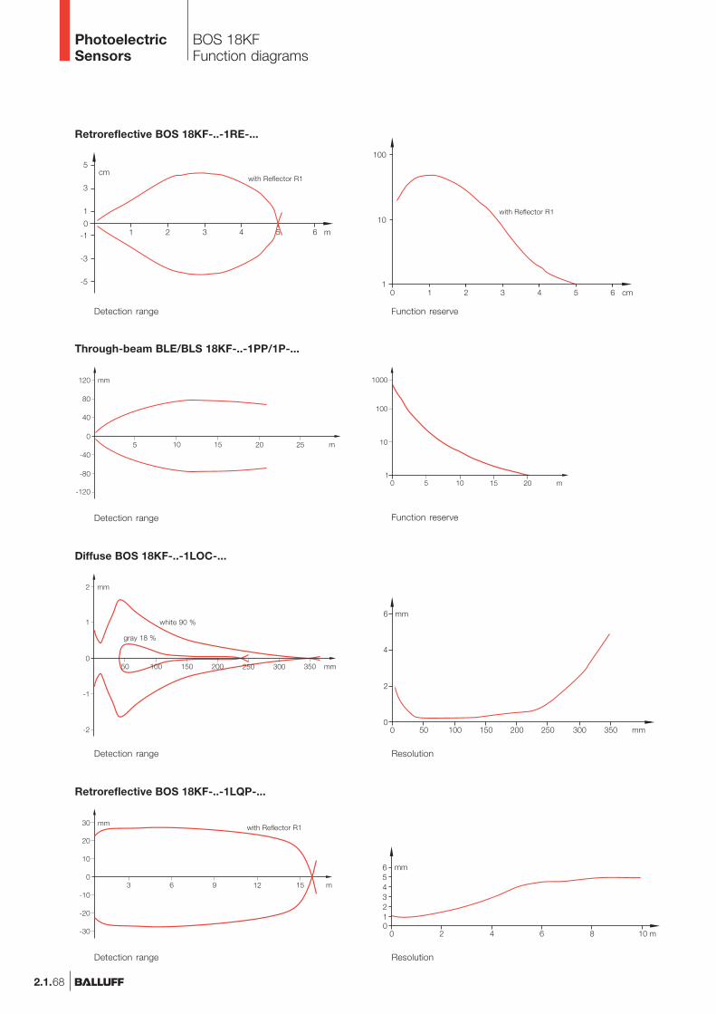
2.1.68
BOS 18KFFunction diagrams
Retroreflective BOS 18KF-..-1RE-...
Detection range Function reserve
with Reflector R1
with Reflector R1
Detection range Function reserve
Through-beam BLE/BLS 18KF-..-1PP/1P-...
Detection range Resolution
Diffuse BOS 18KF-..-1LOC-...
white 90 %
gray 18 %
Retroreflective BOS 18KF-..-1LQP-...
Detection range Resolution
with Reflector R1
PhotoelectricSensors
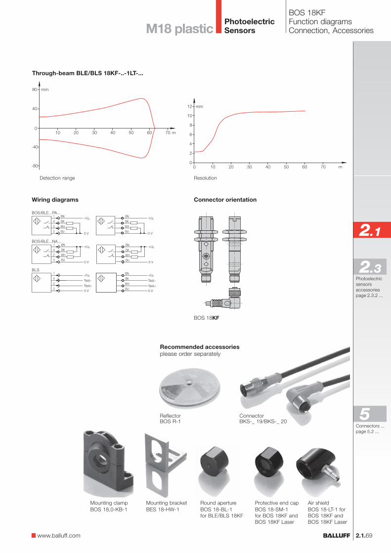
ConnectorBKS-_ 19/BKS-_ 20
ReflectorBOS R-1
Recommended accessoriesplease order separately
BN
BK
WH
BU
+UB
0 V
1
4
2
3
+UB
0 VTest+
Test–
BN
BK
WH
BU
+UB
0 VTest+
Test–
BN
BK
WH
BU
+UB
0 V
2.1.69
2.1
Photoelectricsensorsaccessoriespage 2.3.2 ...
2.3
BOS 18KFFunction diagramsConnection, AccessoriesM18 plastic
Mounting clampBOS 18,0-KB-1
Protective end capBOS 18-SM-1for BOS 18KF andBOS 18KF Laser
Air shieldBOS 18-LT-1 forBOS 18KF andBOS 18KF Laser
Mounting bracketBES 18-HW-1
Round apertureBOS 18-BL-1for BLE/BLS 18KF
Connector orientationWiring diagrams
BOS/BLE...PA...
BOS/BLE...NA...
BLS
BOS 18KF
www.balluff.com
Through-beam BLE/BLS 18KF-..-1LT-...
Detection range Resolution
Connectors ...page 5.2 ...
5
PhotoelectricSensors
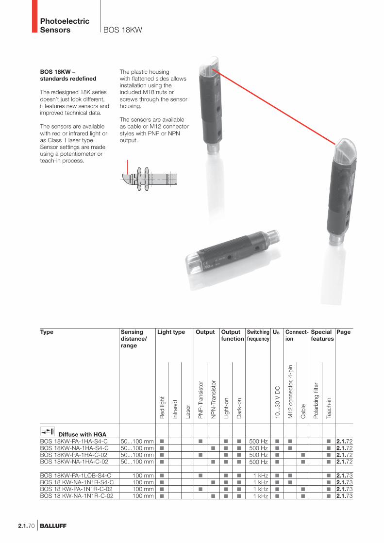
2.1.70
BOS 18KW
BOS 18KW –standards redefined
The redesigned 18K seriesdoesn’t just look different,it features new sensors andimproved technical data.
The sensors are availablewith red or infrared light oras Class 1 laser type.Sensor settings are madeusing a potentiometer orteach-in process.
The plastic housingwith flattened sides allowsinstallation using theincluded M18 nuts orscrews through the sensorhousing.
The sensors are availableas cable or M12 connectorstyles with PNP or NPNoutput.
Type
Diffuse with HGABOS 18KW-PA-1HA-S4-CBOS 18KW-NA-1HA-S4-CBOS 18KW-PA-1HA-C-02BOS 18KW-NA-1HA-C-02
BOS 18KW-PA-1LOB-S4-CBOS 18 KW-NA-1N1R-S4-CBOS 18 KW-PA-1N1R-C-02BOS 18 KW-NA-1N1R-C-02
OutputLight typeSensingdistance/range
50...100 mm50...100 mm50...100 mm50...100 mm
100 mm100 mm100 mm100 mm
Connect-ion
500 Hz500 Hz500 Hz500 Hz
1 kHz1 kHz1 kHz1 kHz
Outputfunction
Page
2.1.722.1.722.1.722.1.72
2.1.732.1.732.1.732.1.73
Specialfeatures
Red
ligh
t
Infra
red
M12
con
nect
or, 4
-pin
Cab
le
10...
30 V
DC
Pol
ariz
ing
filte
r
NP
N-T
rans
isto
r
PN
P-T
rans
isto
r
Ligh
t-on
Dar
k-on
Teac
h-in
UBSwitchingfrequency
Lase
r
PhotoelectricSensors

2.1.71
2.1
Photoelectricsensorsaccessoriespage 2.3.2 ...
2.3
BOS 18KWProduct overview
M18 Plasticwith Angle Head
Type
DiffuseBOS 18KW-PA-1XA-S4-CBOS 18KW-NA-1XA-S4-CBOS 18KW-PA-1XA-C-02BOS 18KW-NA-1XA-C-02
BOS 18KW-PA-1LOB-S4-CBOS 18KW-NA-1LOB-S4-CBOS 18KW-PA-1LOB-C-02BOS 18KW-NA-1LOB-C-02
BOS 18KW-PA-1PD-S4-CBOS 18KW-NA-1PD-S4-CBOS 18KW-PA-1PD-C-02BOS 18KW-NA-1PD-C-02
RetroreflectiveBOS 18KW-PA-1TB-S4-CBOS 18KW-NA-1TB-S4-CBOS 18KW-PA-1TB-C-02BOS 18KW-NA-1TB-C-02
BOS 18KW-PA-1QC-S4-CBOS 18KW-NA-1QC-S4-CBOS 18KW-PA-1QC-C-02BOS 18KW-NA-1QC-C-02
BOS 18KW-PA-1LQH-S4-CBOS 18KW-NA-1LQH-S4-CBOS 18KW-PA-1LQH-C-02BOS 18KW-NA-1LQH-C-02
Through-beamBLE 18KW-PA-1PP-S4-CBLE 18KW-NA-1PP-S4-CBLE 18KW-PA-1PP-C-02BLE 18KW-NA-1PP-C-02
BLE 18KW-PA-1LT-S4-CBLE 18KW-NA-1LT-S4-CBLE 18KW-PA-1LT-C-02BLE 18KW-NA-1LT-C-02
BLS 18KW-XX-1P-S4-LBLS 18KW-XX-1P-L-02
BLS 18KW-XX-1LT-S4-LBLS 18KW-XX-1LT-L-02
OutputLight typeSensingdistance/range
0...80 mm0...80 mm0...80 mm0...80 mm
0...250 mm0...250 mm0...250 mm0...250 mm
0...400 mm0...400 mm0...400 mm0...400 mm
0.1...1.7 m0.1...1.7 m0.1...1.7 m0.1...1.7 m
0.1...3 m0.1...3 m0.1...3 m0.1...3 m
0.1...9 m0.1...9 m0.1...9 m0.1...9 m
0...15 m0...15 m0...15 m0...15 m
0...50 m0...50 m0...50 m0...50 m
0...15 m0...15 m
0...50 m0...50 m
Connec-tion
1 kHz1 kHz1 kHz1 kHz
1.5 kHz1.5 kHz1.5 kHz1.5 kHz
1 kHz1 kHz1 kHz1 kHz
1 kHz1 kHz1 kHz1 kHz
1 kHz1 kHz1 kHz1 kHz
1.5 kHz1.5 kHz1.5 kHz1.5 kHz
250 Hz250 Hz250 Hz250 Hz
1.5 kHz1.5 kHz1.5 kHz1.5 kHz
Outputfunction
Page
2.1.732.1.732.1.732.1.73
2.1.782.1.782.1.782.1.78
2.1.742.1.742.1.742.1.74
2.1.752.1.752.1.752.1.75
2.1.752.1.752.1.752.1.75
2.1.792.1.792.1.792.1.79
2.1.762.1.762.1.772.1.77
2.1.802.1.802.1.812.1.81
2.1.762.1.77
2.1.802.1.81
Specialfeatures
Red
ligh
t
Infra
red
M12
con
nect
or, 4
-pin
Cab
le
10...
30 V
DC
Pol
ariz
ing
filte
r
NP
N-T
rans
isto
r
PN
P-T
rans
isto
r
Ligh
t-on
Dar
k-on
Teac
h-in
UBSwitchingfrequency
Lase
r
www.balluff.com
Connectors ...page 5.2 ...
5
PhotoelectricSensors
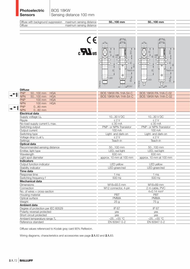
2.1.72
BOS 18KWSensing distance 100 mm
Diffuse with background suppression maximum sensing distanceDiffuse maximum sensing distance
DiffusePNP 50...100 mm HGANPN 50...100 mm HGAPNP 100 mm HGANPN 100 mm HGAPNP 0...80 mmNPN 0...80 mmElectrical dataSupply voltage UB
RippleNo-load supply current I0 max.Switching outputOutput currentSwitching typeVoltage drop Ud at IeSettingsOptical dataRecommended sensing distanceEmitter, light typeWavelengthLight spot diameterIndicatorsOutput function indicatorStability indicatorTime dataResponse timeSwitching frequency fMechanical dataDimensionsConnectionNo. of wires × cross-sectionHousing materialOptical surfaceWeightAmbient dataDegree of protection per IEC 60529Polarity reversal protectedShort circuit protectedAmbient temperature range Ta
Reference standard
50...100 mm
BOS 18KW-PA-1HA-S4-CBOS 18KW-NA-1HA-S4-C
10...30 V DC≤ 2 V
≤ 30 mAPNP- or NPN-Transistor
100 mALight- and dark-on
≤ 2 VTeach-in
50...100 mmLED, red light
630 nmapprox. 10 mm at 100 mm
LED yellowLED green/red
1 ms500 Hz
M18×93.5 mmM12 connector, 4-pin
PBTPMMA25 g
IP 67yesyes
–25...+55 °CEN 60947-5-2
50...100 mm
BOS 18KW-PA-1HA-C-02BOS 18KW-NA-1HA-C-02
10...30 V DC≤ 2 V
≤ 30 mAPNP- or NPN-Transistor
100 mALight- and dark-on
≤ 2 VTeach-in
50...100 mmLED, red light
630 nmapprox. 10 mm at 100 mm
LED yellowLED green/red
1 ms500 Hz
M18×89 mm2 m cable, PVC
4×0.14 mm²PBT
PMMA75 g
IP 67yesyes
–25...+55 °CEN 60947-5-2
Teach-in Teach-in
Diffuse values referenced to Kodak gray card 90% Reflexion.
Wiring diagrams, characteristics and accessories see page 2.1.82 and 2.1.83.
PhotoelectricSensors
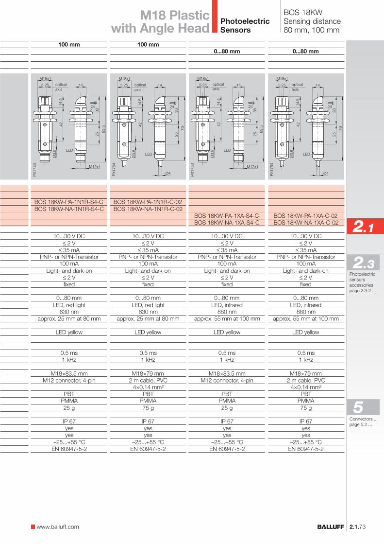
2.1.73
2.1
Photoelectricsensorsaccessoriespage 2.3.2 ...
2.3
BOS 18KWSensing distance80 mm, 100 mm
M18 Plasticwith Angle Head
0...80 mm
BOS 18KW-PA-1XA-S4-CBOS 18KW-NA-1XA-S4-C
10...30 V DC≤ 2 V
≤ 35 mAPNP- or NPN-Transistor
100 mALight- and dark-on
≤ 2 Vfixed
0...80 mmLED, infrared
880 nmapprox. 55 mm at 100 mm
LED yellow
0.5 ms1 kHz
M18×83.5 mmM12 connector, 4-pin
PBTPMMA25 g
IP 67yesyes
–25...+55 °CEN 60947-5-2
0...80 mm
BOS 18KW-PA-1XA-C-02BOS 18KW-NA-1XA-C-02
10...30 V DC≤ 2 V
≤ 35 mAPNP- or NPN-Transistor
100 mALight- and dark-on
≤ 2 Vfixed
0...80 mmLED, infrared
880 nmapprox. 55 mm at 100 mm
LED yellow
0.5 ms1 kHz
M18×79 mm2 m cable, PVC
4×0.14 mm²PBT
PMMA75 g
IP 67yesyes
–25...+55 °CEN 60947-5-2
opticalaxis
opticalaxis
100 mm
BOS 18KW-PA-1N1R-S4-CBOS 18KW-NA-1N1R-S4-C
10...30 V DC≤ 2 V
≤ 35 mAPNP- or NPN-Transistor
100 mALight- and dark-on
≤ 2 Vfixed
0...80 mmLED, red light
630 nmapprox. 25 mm at 80 mm
LED yellow
0.5 ms1 kHz
M18×83.5 mmM12 connector, 4-pin
PBTPMMA25 g
IP 67yesyes
–25...+55 °CEN 60947-5-2
100 mm
BOS 18KW-PA-1N1R-C-02BOS 18KW-NA-1N1R-C-02
10...30 V DC≤ 2 V
≤ 35 mAPNP- or NPN-Transistor
100 mALight- and dark-on
≤ 2 Vfixed
0...80 mmLED, red light
630 nmapprox. 25 mm at 80 mm
LED yellow
0.5 ms1 kHz
M18×79 mm2 m cable, PVC
4×0.14 mm²PBT
PMMA75 g
IP 67yesyes
–25...+55 °CEN 60947-5-2
opticalaxis
opticalaxis
www.balluff.com
Connectors ...page 5.2 ...
5
PhotoelectricSensors
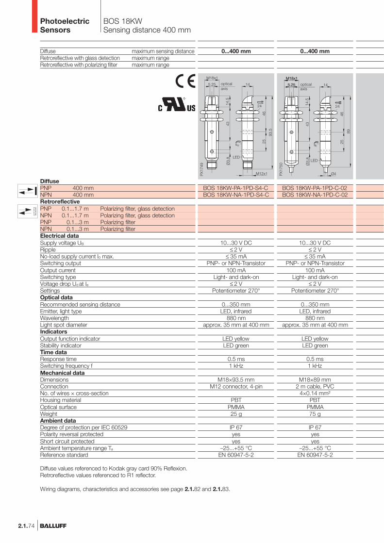
2.1.74
BOS 18KWSensing distance 400 mm
Diffuse maximum sensing distanceRetroreflective with glass detection maximum rangeRetroreflective with polarizing filter maximum range
DiffusePNP 400 mmNPN 400 mmRetroreflectivePNP 0.1...1.7 m Polarizing filter, glass detectionNPN 0.1...1.7 m Polarizing filter, glass detectionPNP 0.1...3 m Polarizing filterNPN 0.1...3 m Polarizing filterElectrical dataSupply voltage UB
RippleNo-load supply current I0 max.Switching outputOutput currentSwitching typeVoltage drop Ud at IeSettingsOptical dataRecommended sensing distanceEmitter, light typeWavelengthLight spot diameterIndicatorsOutput function indicatorStability indicatorTime dataResponse timeSwitching frequency fMechanical dataDimensionsConnectionNo. of wires × cross-sectionHousing materialOptical surfaceWeightAmbient dataDegree of protection per IEC 60529Polarity reversal protectedShort circuit protectedAmbient temperature range Ta
Reference standard
Diffuse values referenced to Kodak gray card 90% Reflexion.Retroreflective values referenced to R1 reflector.
Wiring diagrams, characteristics and accessories see page 2.1.82 and 2.1.83.
0...400 mm
BOS 18KW-PA-1PD-C-02BOS 18KW-NA-1PD-C-02
10...30 V DC≤ 2 V
≤ 35 mAPNP- or NPN-Transistor
100 mALight- and dark-on
≤ 2 VPotentiometer 270°
0...350 mmLED, infrared
880 nmapprox. 35 mm at 400 mm
LED yellowLED green
0.5 ms1 kHz
M18×89 mm2 m cable, PVC
4×0.14 mm²PBT
PMMA75 g
IP 67yesyes
–25...+55 °CEN 60947-5-2
0...400 mm
BOS 18KW-PA-1PD-S4-CBOS 18KW-NA-1PD-S4-C
10...30 V DC≤ 2 V
≤ 35 mAPNP- or NPN-Transistor
100 mALight- and dark-on
≤ 2 VPotentiometer 270°
0...350 mmLED, infrared
880 nmapprox. 35 mm at 400 mm
LED yellowLED green
0.5 ms1 kHz
M18×93.5 mmM12 connector, 4-pin
PBTPMMA25 g
IP 67yesyes
–25...+55 °CEN 60947-5-2
opticalaxis
opticalaxis
PhotoelectricSensors
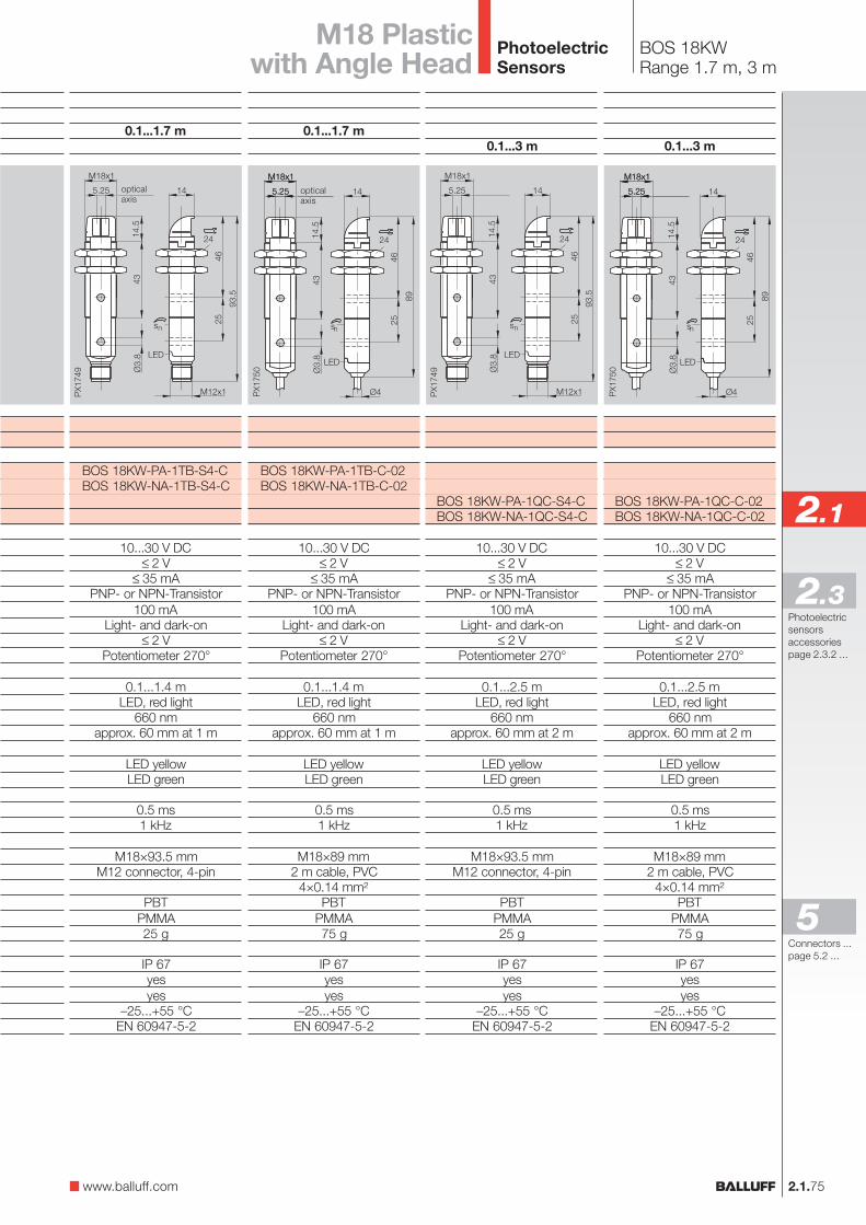
2.1.75
2.1
Photoelectricsensorsaccessoriespage 2.3.2 ...
2.3
BOS 18KWRange 1.7 m, 3 m
M18 Plasticwith Angle Head
opticalaxis
opticalaxis
0.1...1.7 m
BOS 18KW-PA-1TB-S4-CBOS 18KW-NA-1TB-S4-C
10...30 V DC≤ 2 V
≤ 35 mAPNP- or NPN-Transistor
100 mALight- and dark-on
≤ 2 VPotentiometer 270°
0.1...1.4 mLED, red light
660 nmapprox. 60 mm at 1 m
LED yellowLED green
0.5 ms1 kHz
M18×93.5 mmM12 connector, 4-pin
PBTPMMA25 g
IP 67yesyes
–25...+55 °CEN 60947-5-2
0.1...1.7 m
BOS 18KW-PA-1TB-C-02BOS 18KW-NA-1TB-C-02
10...30 V DC≤ 2 V
≤ 35 mAPNP- or NPN-Transistor
100 mALight- and dark-on
≤ 2 VPotentiometer 270°
0.1...1.4 mLED, red light
660 nmapprox. 60 mm at 1 m
LED yellowLED green
0.5 ms1 kHz
M18×89 mm2 m cable, PVC
4×0.14 mm²PBT
PMMA75 g
IP 67yesyes
–25...+55 °CEN 60947-5-2
0.1...3 m
BOS 18KW-PA-1QC-S4-CBOS 18KW-NA-1QC-S4-C
10...30 V DC≤ 2 V
≤ 35 mAPNP- or NPN-Transistor
100 mALight- and dark-on
≤ 2 VPotentiometer 270°
0.1...2.5 mLED, red light
660 nmapprox. 60 mm at 2 m
LED yellowLED green
0.5 ms1 kHz
M18×93.5 mmM12 connector, 4-pin
PBTPMMA25 g
IP 67yesyes
–25...+55 °CEN 60947-5-2
0.1...3 m
BOS 18KW-PA-1QC-C-02BOS 18KW-NA-1QC-C-02
10...30 V DC≤ 2 V
≤ 35 mAPNP- or NPN-Transistor
100 mALight- and dark-on
≤ 2 VPotentiometer 270°
0.1...2.5 mLED, red light
660 nmapprox. 60 mm at 2 m
LED yellowLED green
0.5 ms1 kHz
M18×89 mm2 m cable, PVC
4×0.14 mm²PBT
PMMA75 g
IP 67yesyes
–25...+55 °CEN 60947-5-2
www.balluff.com
Connectors ...page 5.2 ...
5
PhotoelectricSensors
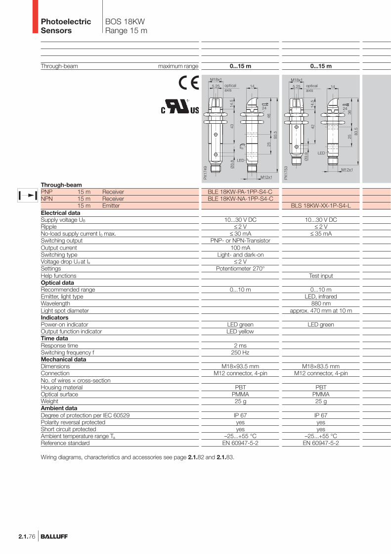
2.1.76
BOS 18KWRange 15 m
Wiring diagrams, characteristics and accessories see page 2.1.82 and 2.1.83.
Through-beam maximum range
Through-beamPNP 15 m ReceiverNPN 15 m Receiver
15 m EmitterElectrical dataSupply voltage UB
RippleNo-load supply current I0 max.Switching outputOutput currentSwitching typeVoltage drop Ud at IeSettingsHelp functionsOptical dataRecommended rangeEmitter, light typeWavelengthLight spot diameterIndicatorsPower-on indicatorOutput function indicatorTime dataResponse timeSwitching frequency fMechanical dataDimensionsConnectionNo. of wires × cross-sectionHousing materialOptical surfaceWeightAmbient dataDegree of protection per IEC 60529Polarity reversal protectedShort circuit protectedAmbient temperature range Ta
Reference standard
0...15 m
BLE 18KW-PA-1PP-S4-CBLE 18KW-NA-1PP-S4-C
10...30 V DC≤ 2 V
≤ 30 mAPNP- or NPN-Transistor
100 mALight- and dark-on
≤ 2 VPotentiometer 270°
0...10 m
LED greenLED yellow
2 ms250 Hz
M18×93.5 mmM12 connector, 4-pin
PBTPMMA25 g
IP 67yesyes
–25...+55 °CEN 60947-5-2
0...15 m
BLS 18KW-XX-1P-S4-L
10...30 V DC≤ 2 V
≤ 35 mA
Test input
0...10 mLED, infrared
880 nmapprox. 470 mm at 10 m
LED green
M18×83.5 mmM12 connector, 4-pin
PBTPMMA25 g
IP 67yesyes
–25...+55 °CEN 60947-5-2
opticalaxis
opticalaxis
PhotoelectricSensors

2.1.77
2.1
Photoelectricsensorsaccessoriespage 2.3.2 ...
2.3
BOS 18KWRange 15 m
M18 Plasticwith Angle Head
0...15 m
BLS 18KW-XX-1P-L-02
10...30 V DC≤ 2 V
≤ 35 mA
Test input
0...10 mLED, infrared
880 nmapprox. 470 mm at 10 m
LED green
M18×79 mm2 m cable, PVC
4×0.14 mm²PBT
PMMA75 g
IP 67yesyes
–25...+55 °CEN 60947-5-2
0...15 m
BLE 18KW-PA-1PP-C-02BLE 18KW-NA-1PP-C-02
10...30 V DC≤ 2 V
≤ 30 mAPNP- or NPN-Transistor
100 mALight- and dark-on
≤ 2 VPotentiometer 270°
0...10 m
LED greenLED yellow
2 ms250 Hz
M18×89 mm2 m cable, PVC
4×0.14 mm²PBT
PMMA75 g
IP 67yesyes
–25...+55 °CEN 60947-5-2
opticalaxis
opticalaxis
www.balluff.com
Connectors ...page 5.2 ...
5
PhotoelectricSensors
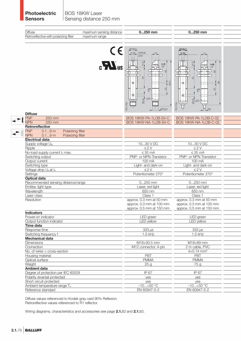
2.1.78
BOS 18KW LaserSensing distance 250 mm
Diffuse maximum sensing distanceRetroreflective with polarizing filter maximum range
DiffusePNP 250 mmNPN 250 mmRetroreflectivePNP 0.1...9 m Polarizing filterNPN 0.1...9 m Polarizing filterElectrical dataSupply voltage UB
RippleNo-load supply current I0 max.Switching outputOutput currentSwitching typeVoltage drop Ud at IeSettingsOptical dataRecommended sensing distance/rangeEmitter, light typeWavelengthLaser classResolution
IndicatorsPower-on indicatorOutput function indicatorTime dataResponse timeSwitching frequency fMechanical dataDimensionsConnectionNo. of wires × cross-sectionHousing materialOptical surfaceWeightAmbient dataDegree of protection per IEC 60529Polarity reversal protectedShort circuit protectedAmbient temperature range Ta
Reference standard
0...250 mm
BOS 18KW-PA-1LOB-S4-CBOS 18KW-NA-1LOB-S4-C
10...30 V DC≤ 2 V
≤ 35 mAPNP- or NPN-Transistor
100 mALight- and dark-on
≤ 2 VPotentiometer 270°
0...250 mmLaser, red light
650 nmClass 1
approx. 0.3 mm at 50 mmapprox. 0.3 mm at 100 mmapprox. 0.5 mm at 150 mm
LED greenLED yellow
333 µs1.5 kHz
M18×93.5 mmM12 connector, 4-pin
PBTPMMA25 g
IP 67yesyes
–10...+50 °CEN 60947-5-2
opticalaxis
0...250 mm
BOS 18KW-PA-1LOB-C-02BOS 18KW-NA-1LOB-C-02
10...30 V DC≤ 2 V
≤ 35 mAPNP- or NPN-Transistor
100 mALight- and dark-on
≤ 2 VPotentiometer 270°
0...250 mmLaser, red light
650 nmClass 1
approx. 0.3 mm at 50 mmapprox. 0.3 mm at 100 mmapprox. 0.5 mm at 150 mm
LED greenLED yellow
333 µs1.5 kHz
M18×89 mm2 m cable, PVC
4×0.14 mm²PBT
PMMA75 g
IP 67yesyes
–10...+50 °CEN 60947-5-2
Diffuse values referenced to Kodak gray card 90% Reflexion.Retroreflective values referenced to R1 reflector.
Wiring diagrams, characteristics and accessories see page 2.1.82 and 2.1.83.
PhotoelectricSensors
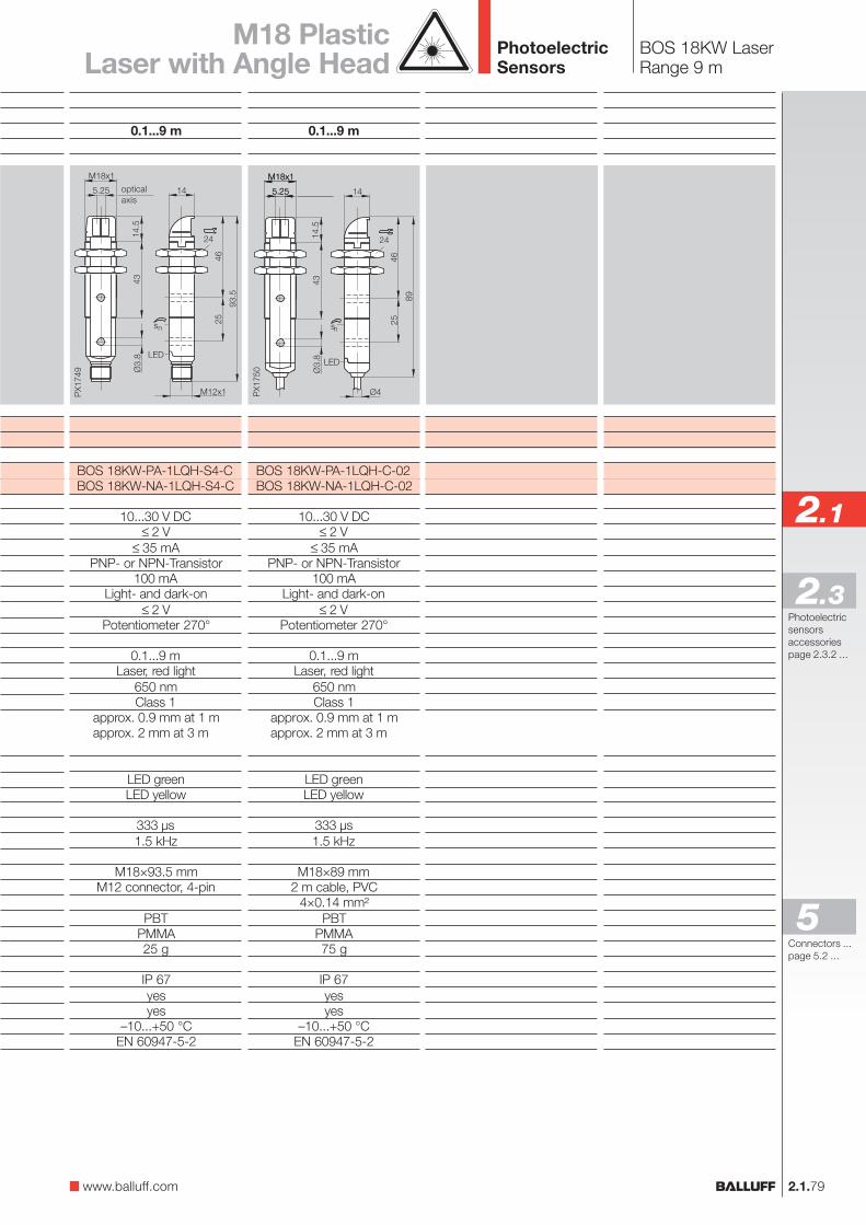
2.1.79
2.1
Photoelectricsensorsaccessoriespage 2.3.2 ...
2.3
BOS 18KW LaserRange 9 m
M18 PlasticLaser with Angle Head
0.1...9 m
BOS 18KW-PA-1LQH-S4-CBOS 18KW-NA-1LQH-S4-C
10...30 V DC≤ 2 V
≤ 35 mAPNP- or NPN-Transistor
100 mALight- and dark-on
≤ 2 VPotentiometer 270°
0.1...9 mLaser, red light
650 nmClass 1
approx. 0.9 mm at 1 mapprox. 2 mm at 3 m
LED greenLED yellow
333 µs1.5 kHz
M18×93.5 mmM12 connector, 4-pin
PBTPMMA25 g
IP 67yesyes
–10...+50 °CEN 60947-5-2
opticalaxis
0.1...9 m
BOS 18KW-PA-1LQH-C-02BOS 18KW-NA-1LQH-C-02
10...30 V DC≤ 2 V
≤ 35 mAPNP- or NPN-Transistor
100 mALight- and dark-on
≤ 2 VPotentiometer 270°
0.1...9 mLaser, red light
650 nmClass 1
approx. 0.9 mm at 1 mapprox. 2 mm at 3 m
LED greenLED yellow
333 µs1.5 kHz
M18×89 mm2 m cable, PVC
4×0.14 mm²PBT
PMMA75 g
IP 67yesyes
–10...+50 °CEN 60947-5-2
www.balluff.com
Connectors ...page 5.2 ...
5
PhotoelectricSensors
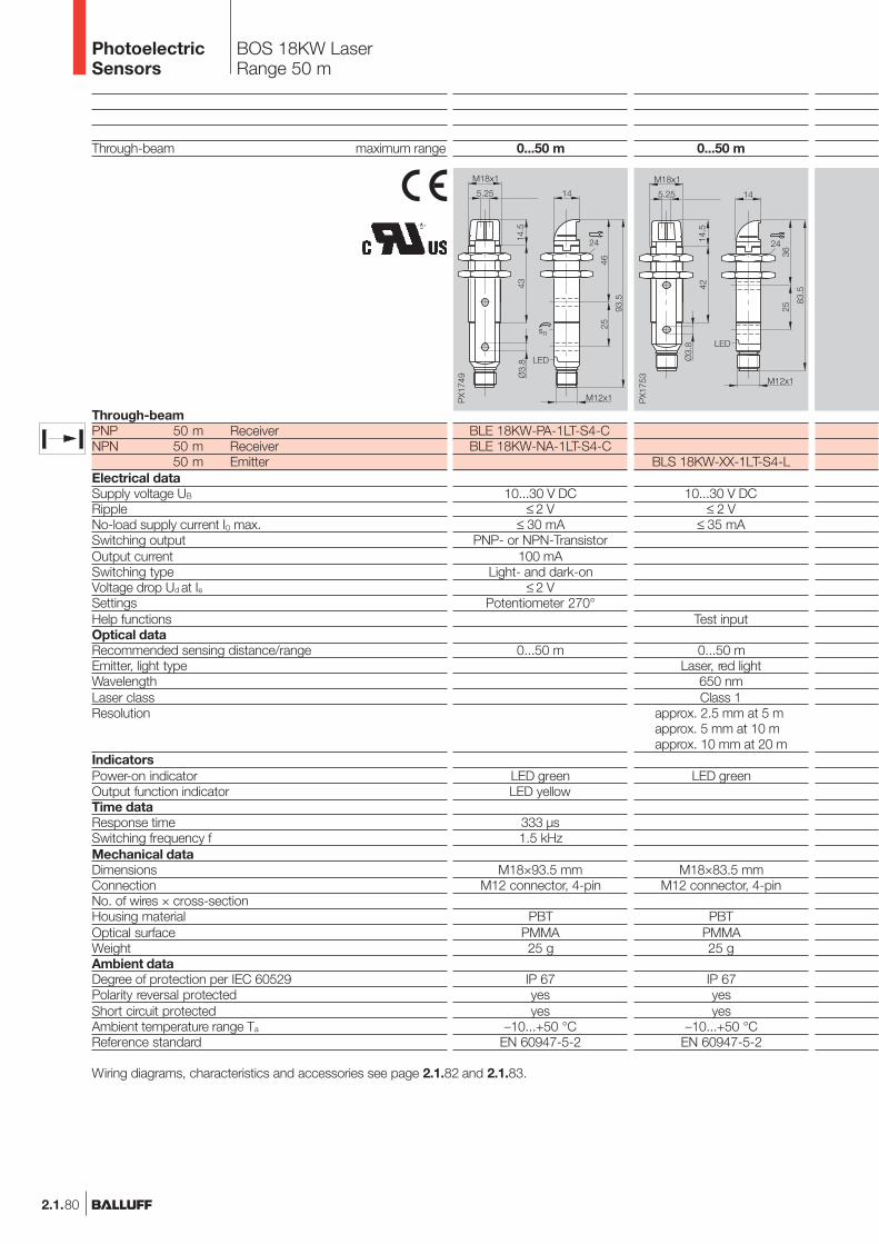
2.1.80
BOS 18KW LaserRange 50 m
Through-beam maximum range
Through-beamPNP 50 m ReceiverNPN 50 m Receiver
50 m EmitterElectrical dataSupply voltage UB
RippleNo-load supply current I0 max.Switching outputOutput currentSwitching typeVoltage drop Ud at IeSettingsHelp functionsOptical dataRecommended sensing distance/rangeEmitter, light typeWavelengthLaser classResolution
IndicatorsPower-on indicatorOutput function indicatorTime dataResponse timeSwitching frequency fMechanical dataDimensionsConnectionNo. of wires × cross-sectionHousing materialOptical surfaceWeightAmbient dataDegree of protection per IEC 60529Polarity reversal protectedShort circuit protectedAmbient temperature range Ta
Reference standard
0...50 m
BLS 18KW-XX-1LT-S4-L
10...30 V DC≤ 2 V
≤ 35 mA
Test input
0...50 mLaser, red light
650 nmClass 1
approx. 2.5 mm at 5 mapprox. 5 mm at 10 mapprox. 10 mm at 20 m
LED green
M18×83.5 mmM12 connector, 4-pin
PBTPMMA25 g
IP 67yesyes
–10...+50 °CEN 60947-5-2
0...50 m
BLE 18KW-PA-1LT-S4-CBLE 18KW-NA-1LT-S4-C
10...30 V DC≤ 2 V
≤ 30 mAPNP- or NPN-Transistor
100 mALight- and dark-on
≤ 2 VPotentiometer 270°
0...50 m
LED greenLED yellow
333 µs1.5 kHz
M18×93.5 mmM12 connector, 4-pin
PBTPMMA25 g
IP 67yesyes
–10...+50 °CEN 60947-5-2
Wiring diagrams, characteristics and accessories see page 2.1.82 and 2.1.83.
PhotoelectricSensors
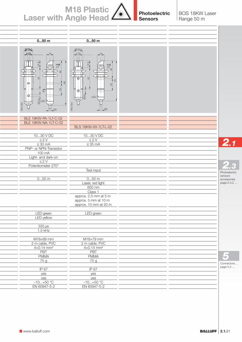
2.1.81
2.1
Photoelectricsensorsaccessoriespage 2.3.2 ...
2.3
BOS 18KW LaserRange 50 m
M18 PlasticLaser with Angle Head
0...50 m
BLS 18KW-XX-1LT-L-02
10...30 V DC≤ 2 V
≤ 35 mA
Test input
0...50 mLaser, red light
650 nmClass 1
approx. 2.5 mm at 5 mapprox. 5 mm at 10 mapprox. 10 mm at 20 m
LED green
M18×79 mm2 m cable, PVC
4×0.14 mm²PBT
PMMA75 g
IP 67yesyes
–10...+50 °CEN 60947-5-2
0...50 m
BLE 18KW-PA-1LT-C-02BLE 18KW-NA-1LT-C-02
10...30 V DC≤ 2 V
≤ 30 mAPNP- or NPN-Transistor
100 mALight- and dark-on
≤ 2 VPotentiometer 270°
0...50 m
LED greenLED yellow
333 µs1.5 kHz
M18×89 mm2 m cable, PVC
4×0.14 mm²PBT
PMMA75 g
IP 67yesyes
–10...+50 °CEN 60947-5-2
www.balluff.com
Connectors ...page 5.2 ...
5
PhotoelectricSensors
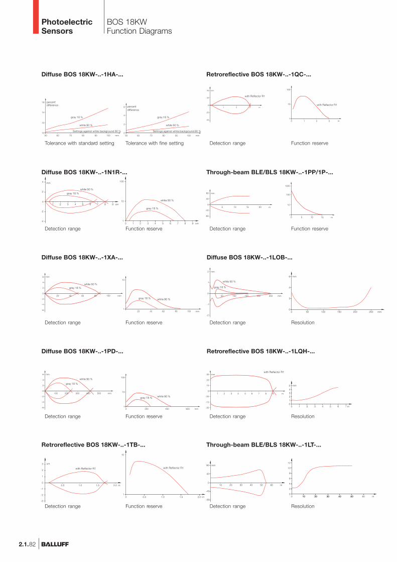
2.1.82
BOS 18KWFunction Diagrams
Tolerance with standard setting
Diffuse BOS 18KW-..-1HA-...
Tolerance with fine setting
percentdifference percent
difference
Diffuse BOS 18KW-..-1XA-...
Diffuse BOS 18KW-..-1PD-...
Detection range
Detection range
Function reserve
Function reserve
white 90 %gray 18 %
white 90 %gray 18 %
white 90 %
gray 18 %
gray 18 %
Settings against white background 90 % Settings against white background 90 %
white 90 %
gray 18 %
white 90 %
gray 18 %
white 90 %
Retroreflective BOS 18KW-..-1TB-...
Diffuse BOS 18KW-..-1N1R-...
Detection range
Detection range
Detection range Resolution
Diffuse BOS 18KW-..-1LOB-...
Retroreflective BOS 18KW-..-1LQH-...
Through-beam BLE/BLS 18KW-..-1LT-...
Detection range Resolution
Detection range Resolution
white 90 %
gray 18 %
with Reflector R1
Function reserve
Through-beam BLE/BLS 18KW-..-1PP/1P-...
Function reserve
Detection range
Detection range
Retroreflective BOS 18KW-..-1QC-...
with Reflector R1
with Reflector R1
white 90 %
gray 18 %
white 90 %
gray 18 %
with Reflector R1 with Reflector R1
Function reserve
Function reserve
PhotoelectricSensors
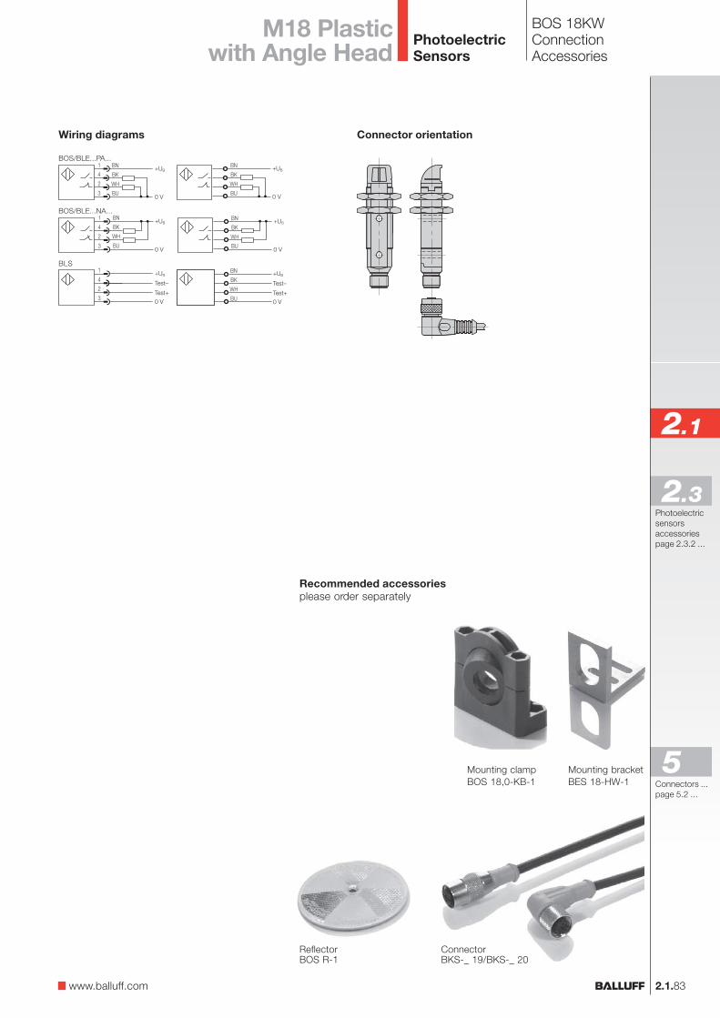
BN
BK
WH
BU
+UB
0 V
1
4
2
3
+UB
0 VTest+
Test–
BN
BK
WH
BU
+UB
0 VTest+
Test–
BN
BK
WH
BU
+UB
0 V
2.1.83
2.1
Photoelectricsensorsaccessoriespage 2.3.2 ...
2.3
BOS 18KWConnectionAccessories
M18 Plasticwith Angle Head
Mounting clampBOS 18,0-KB-1
Mounting bracketBES 18-HW-1
ConnectorBKS-_ 19/BKS-_ 20
Connector orientationWiring diagrams
BOS/BLE...PA...
BOS/BLE...NA...
BLS
ReflectorBOS R-1
Recommended accessoriesplease order separately
www.balluff.com
Connectors ...page 5.2 ...
5
PhotoelectricSensors
2.1.84
BOS 18K(R)
With our BOS 18K(R)Balluff offers a particularlyeconomical automationsolution for detecting objectsin any application.
Diffuse, retroreflective andthrough-beam sensorsin axial and radial configura-tion, with PNP or NPNoutput, as well as cable orconnector, versions areavailable.
PhotoelectricSensors
2.1.85
2.1
Photoelectricsensorsaccessoriespage 2.3.2 ...
2.3
BOS 18K(R)Product Overview
Type
DiffuseBOS 18K-PU-ID10-S4BOS 18K-NU-ID10-S4BOS 18K-PU-ID10-02BOS 18K-NU-ID10-02
BOS 18KR-PU-ID10-S4BOS 18KR-NU-ID10-S4BOS 18KR-PU-ID10-02BOS 18KR-NU-ID10-02
RetroreflectiveBOS 18K-PU-PR10-S4BOS 18K-NU-PR10-S4BOS 18K-PU-PR10-02BOS 18K-NU-PR10-02
BOS 18KR-PU-PR10-S4BOS 18KR-NU-PR10-S4BOS 18KR-PU-PR10-02BOS 18KR-NU-PR10-02
Through-beamBOS 18K-PU-IE10-S4BOS 18K-NU-IE10-S4BOS 18K-PU-IE10-02BOS 18K-NU-IE10-02
BOS 18K-XT-IS10-S4BOS 18K-XT-IS10-02
BOS 18KR-PU-IE10-S4BOS 18KR-NU-IE10-S4BOS 18KR-PU-IE10-02BOS 18KR-NU-IE10-02
BOS 18KR-XT-IS10-S4BOS 18KR-XT-IS10-02
OutputLighttype
Sensingdistance/range
0...300 mm0...300 mm0...300 mm0...300 mm
0...250 mm0...250 mm0...250 mm0...250 mm
0.1...2.2 m0.1...2.2 m0.1...2.2 m0.1...2.2 m
0.1...1.7 m0.1...1.7 m0.1...1.7 m0.1...1.7 m
0...13 m0...13 m0...13 m0...13 m
0...13 m0...13 m
0...11 m0...11 m0...11 m0...11 m
0...11 m0...11 m
Connec-tion
500 Hz500 Hz500 Hz500 Hz
500 Hz500 Hz500 Hz500 Hz
500 Hz500 Hz500 Hz500 Hz
500 Hz500 Hz500 Hz500 Hz
250 Hz250 Hz250 Hz250 Hz
250 Hz250 Hz250 Hz250 Hz
Outputfunction
Page
2.1.862.1.862.1.862.1.86
2.1.882.1.882.1.882.1.88
2.1.862.1.862.1.872.1.87
2.1.882.1.882.1.892.1.89
2.1.872.1.872.1.872.1.87
2.1.872.1.87
2.1.892.1.892.1.892.1.89
2.1.892.1.89
Specialfeatures
Red
ligh
t
Infra
red
M12
con
nect
or, 4
-pin
Cab
le
10...
30 V
DC
Pol
ariz
ing
filte
r
NP
N-T
rans
isto
r
PN
P-T
rans
isto
r
Ligh
t-on
Dar
k-on
UBSwitchingfrequency
M18 Plastic
Lightexit
Str
aigh
t
Rig
ht a
ngle
www.balluff.com
Connectors ...page 5.2 ...
5
PhotoelectricSensors
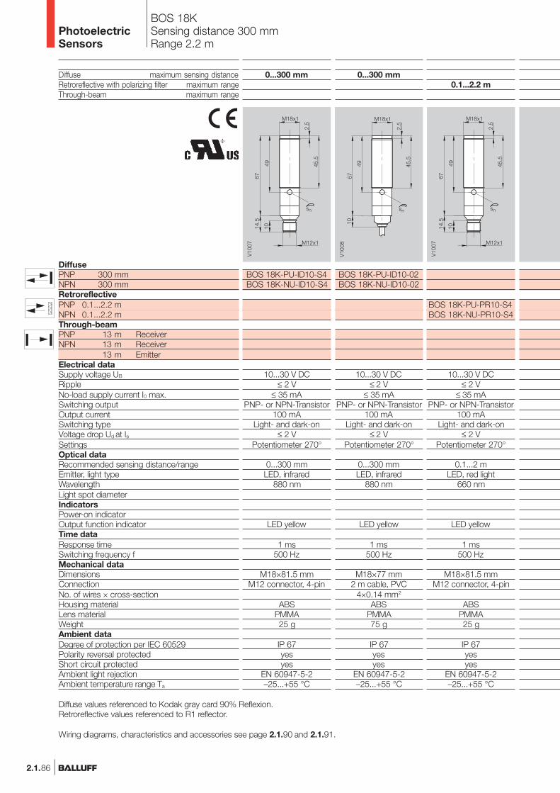
2.1.86
BOS 18KSensing distance 300 mmRange 2.2 m
Diffuse maximum sensing distanceRetroreflective with polarizing filter maximum rangeThrough-beam maximum range
DiffusePNP 300 mmNPN 300 mmRetroreflectivePNP 0.1...2.2 mNPN 0.1...2.2 mThrough-beamPNP 13 m ReceiverNPN 13 m Receiver
13 m EmitterElectrical dataSupply voltage UB
RippleNo-load supply current I0 max.Switching outputOutput currentSwitching typeVoltage drop Ud at IeSettingsOptical dataRecommended sensing distance/rangeEmitter, light typeWavelengthLight spot diameterIndicatorsPower-on indicatorOutput function indicatorTime dataResponse timeSwitching frequency fMechanical dataDimensionsConnectionNo. of wires × cross-sectionHousing materialLens materialWeightAmbient dataDegree of protection per IEC 60529Polarity reversal protectedShort circuit protectedAmbient light rejectionAmbient temperature range Ta
0.1...2.2 m
BOS 18K-PU-PR10-S4BOS 18K-NU-PR10-S4
10...30 V DC≤ 2 V
≤ 35 mAPNP- or NPN-Transistor
100 mALight- and dark-on
≤ 2 VPotentiometer 270°
0.1...2 mLED, red light
660 nm
LED yellow
1 ms500 Hz
M18×81.5 mmM12 connector, 4-pin
ABSPMMA25 g
IP 67yesyes
EN 60947-5-2–25...+55 °C
0...300 mm
BOS 18K-PU-ID10-S4BOS 18K-NU-ID10-S4
10...30 V DC≤ 2 V
≤ 35 mAPNP- or NPN-Transistor
100 mALight- and dark-on
≤ 2 VPotentiometer 270°
0...300 mmLED, infrared
880 nm
LED yellow
1 ms500 Hz
M18×81.5 mmM12 connector, 4-pin
ABSPMMA25 g
IP 67yesyes
EN 60947-5-2–25...+55 °C
0...300 mm
BOS 18K-PU-ID10-02BOS 18K-NU-ID10-02
10...30 V DC≤ 2 V
≤ 35 mAPNP- or NPN-Transistor
100 mALight- and dark-on
≤ 2 VPotentiometer 270°
0...300 mmLED, infrared
880 nm
LED yellow
1 ms500 Hz
M18×77 mm2 m cable, PVC
4×0.14 mm2
ABSPMMA75 g
IP 67yesyes
EN 60947-5-2–25...+55 °C
Diffuse values referenced to Kodak gray card 90% Reflexion.Retroreflective values referenced to R1 reflector.
Wiring diagrams, characteristics and accessories see page 2.1.90 and 2.1.91.
PhotoelectricSensors

2.1.87
2.1
Photoelectricsensorsaccessoriespage 2.3.2 ...
2.3
BOS 18KRange 2.2 m, 13 mM18 Plastic
0.1...2.2 m
BOS 18K-PU-PR10-02BOS 18K-NU-PR10-02
10...30 V DC≤ 2 V
≤ 35 mAPNP- or NPN-Transistor
100 mALight- and dark-on
≤ 2 VPotentiometer 270°
0.1...2 mLED, red light
660 nm
LED yellow
1 ms500 Hz
M18×77 mm2 m cable, PVC
4×0.14 mm2
ABSPMMA75 g
IP 67yesyes
EN 60947-5-2–25...+55 °C
0...13 m
BOS 18K-XT-IS10-S4
10...30 V DC≤ 2 V
≤ 35 mA
fixed
0...12 mLED, infrared
880 nm
LED green
M18×71.5 mmM12 connector, 4-pin
ABSPMMA25 g
IP 67yesyes
EN 60947-5-2–25...+55 °C
0...13 m
BOS 18K-PU-IE10-02BOS 18K-NU-IE10-02
10...30 V DC≤ 2 V
≤ 35 mAPNP- or NPN-Transistor
100 mALight- and dark-on
≤ 2 Vfixed
0...12 m
LED yellow
2 ms250 Hz
M18×77 mm2 m cable, PVC
4×0.14 mm2
ABSPMMA75 g
IP 67yesyes
EN 60947-5-2–25...+55 °C
0...13 m
BOS 18K-PU-IE10-S4BOS 18K-NU-IE10-S4
10...30 V DC≤ 2 V
≤ 35 mAPNP- or NPN-Transistor
100 mALight- and dark-on
≤ 2 Vfixed
0...12 m
LED yellow
2 ms250 Hz
M18×81.5 mmM12 connector, 4-pin
ABSPMMA25 g
IP 67yesyes
EN 60947-5-2–25...+55 °C
0...13 m
BOS 18K-XT-IS10-02
10...30 V DC≤ 2 V
≤ 35 mA
fixed
0...12 mLED, infrared
880 nm
LED green
M18×67 mm2 m cable, PVC
4×0.14 mm2
ABSPMMA75 g
IP 67yesyes
EN 60947-5-2–25...+55 °C
www.balluff.com
Connectors ...page 5.2 ...
5
PhotoelectricSensors
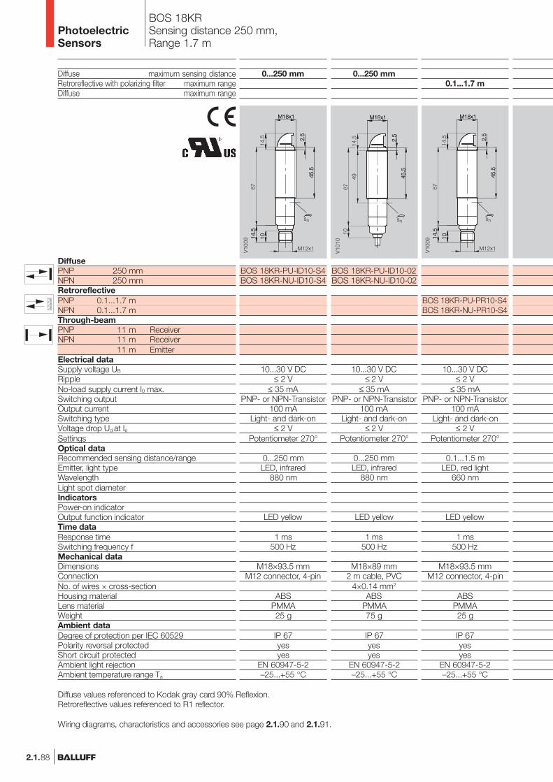
2.1.88
BOS 18KRSensing distance 250 mm,Range 1.7 m
Diffuse maximum sensing distanceRetroreflective with polarizing filter maximum rangeDiffuse maximum range
DiffusePNP 250 mmNPN 250 mmRetroreflectivePNP 0.1...1.7 mNPN 0.1...1.7 mThrough-beamPNP 11 m ReceiverNPN 11 m Receiver
11 m EmitterElectrical dataSupply voltage UB
RippleNo-load supply current I0 max.Switching outputOutput currentSwitching typeVoltage drop Ud at IeSettingsOptical dataRecommended sensing distance/rangeEmitter, light typeWavelengthLight spot diameterIndicatorsPower-on indicatorOutput function indicatorTime dataResponse timeSwitching frequency fMechanical dataDimensionsConnectionNo. of wires × cross-sectionHousing materialLens materialWeightAmbient dataDegree of protection per IEC 60529Polarity reversal protectedShort circuit protectedAmbient light rejectionAmbient temperature range Ta
0.1...1.7 m
BOS 18KR-PU-PR10-S4BOS 18KR-NU-PR10-S4
10...30 V DC≤ 2 V
≤ 35 mAPNP- or NPN-Transistor
100 mALight- and dark-on
≤ 2 VPotentiometer 270°
0.1...1.5 mLED, red light
660 nm
LED yellow
1 ms500 Hz
M18×93.5 mmM12 connector, 4-pin
ABSPMMA25 g
IP 67yesyes
EN 60947-5-2–25...+55 °C
0...250 mm
BOS 18KR-PU-ID10-S4BOS 18KR-NU-ID10-S4
10...30 V DC≤ 2 V
≤ 35 mAPNP- or NPN-Transistor
100 mALight- and dark-on
≤ 2 VPotentiometer 270°
0...250 mmLED, infrared
880 nm
LED yellow
1 ms500 Hz
M18×93.5 mmM12 connector, 4-pin
ABSPMMA25 g
IP 67yesyes
EN 60947-5-2–25...+55 °C
0...250 mm
BOS 18KR-PU-ID10-02BOS 18KR-NU-ID10-02
10...30 V DC≤ 2 V
≤ 35 mAPNP- or NPN-Transistor
100 mALight- and dark-on
≤ 2 VPotentiometer 270°
0...250 mmLED, infrared
880 nm
LED yellow
1 ms500 Hz
M18×89 mm2 m cable, PVC
4×0.14 mm2
ABSPMMA75 g
IP 67yesyes
EN 60947-5-2–25...+55 °C
Diffuse values referenced to Kodak gray card 90% Reflexion.Retroreflective values referenced to R1 reflector.
Wiring diagrams, characteristics and accessories see page 2.1.90 and 2.1.91.
PhotoelectricSensors
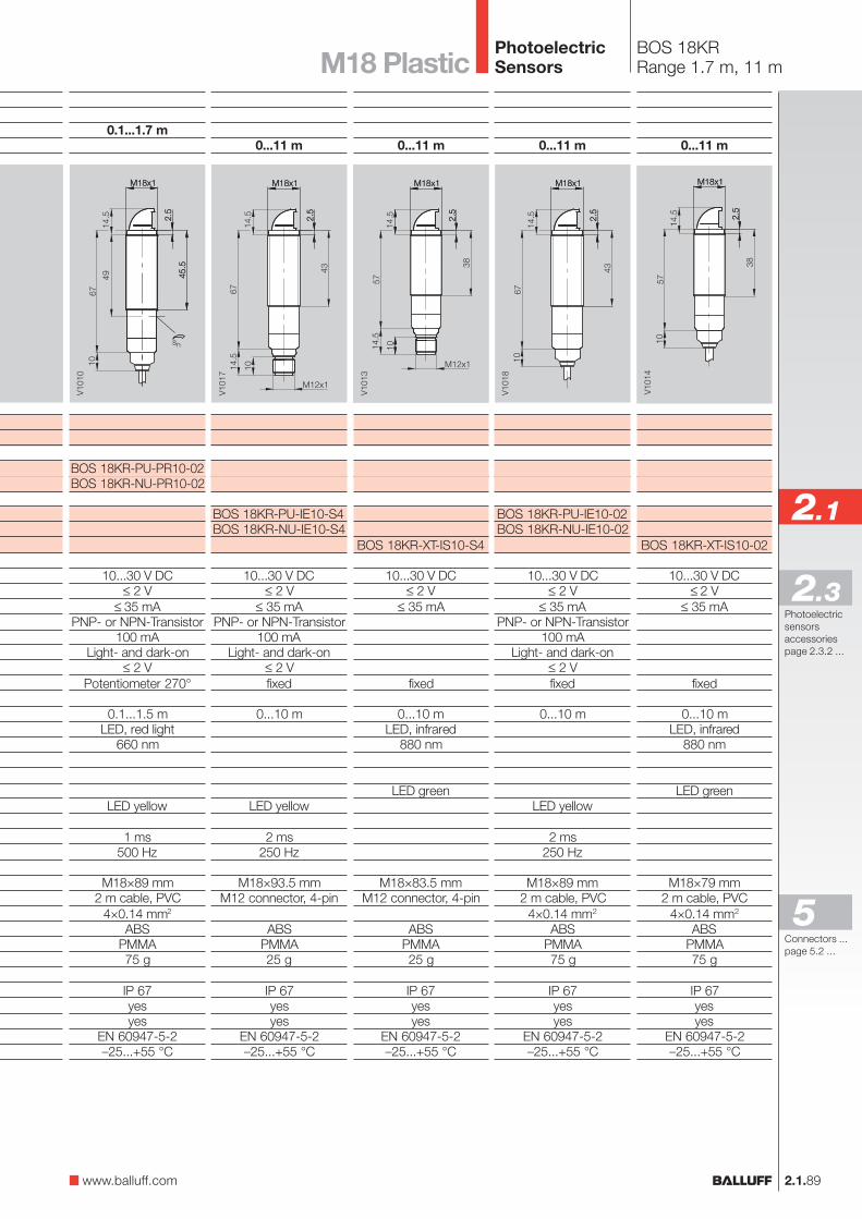
2.1.89
2.1
Photoelectricsensorsaccessoriespage 2.3.2 ...
2.3
BOS 18KRRange 1.7 m, 11 m
0.1...1.7 m
BOS 18KR-PU-PR10-02BOS 18KR-NU-PR10-02
10...30 V DC≤ 2 V
≤ 35 mAPNP- or NPN-Transistor
100 mALight- and dark-on
≤ 2 VPotentiometer 270°
0.1...1.5 mLED, red light
660 nm
LED yellow
1 ms500 Hz
M18×89 mm2 m cable, PVC
4×0.14 mm2
ABSPMMA75 g
IP 67yesyes
EN 60947-5-2–25...+55 °C
0...11 m
BOS 18KR-PU-IE10-S4BOS 18KR-NU-IE10-S4
10...30 V DC≤ 2 V
≤ 35 mAPNP- or NPN-Transistor
100 mALight- and dark-on
≤ 2 Vfixed
0...10 m
LED yellow
2 ms250 Hz
M18×93.5 mmM12 connector, 4-pin
ABSPMMA25 g
IP 67yesyes
EN 60947-5-2–25...+55 °C
0...11 m
BOS 18KR-XT-IS10-S4
10...30 V DC≤ 2 V
≤ 35 mA
fixed
0...10 mLED, infrared
880 nm
LED green
M18×83.5 mmM12 connector, 4-pin
ABSPMMA25 g
IP 67yesyes
EN 60947-5-2–25...+55 °C
0...11 m
BOS 18KR-PU-IE10-02BOS 18KR-NU-IE10-02
10...30 V DC≤ 2 V
≤ 35 mAPNP- or NPN-Transistor
100 mALight- and dark-on
≤ 2 Vfixed
0...10 m
LED yellow
2 ms250 Hz
M18×89 mm2 m cable, PVC
4×0.14 mm2
ABSPMMA75 g
IP 67yesyes
EN 60947-5-2–25...+55 °C
0...11 m
BOS 18KR-XT-IS10-02
10...30 V DC≤ 2 V
≤ 35 mA
fixed
0...10 mLED, infrared
880 nm
LED green
M18×79 mm2 m cable, PVC
4×0.14 mm2
ABSPMMA75 g
IP 67yesyes
EN 60947-5-2–25...+55 °C
www.balluff.com
M18 Plastic
Connectors ...page 5.2 ...
5
PhotoelectricSensors
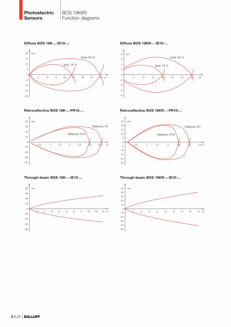
2.1.90
BOS 18K(R)Function diagrams
Diffuse BOS 18K-..-ID10-... Diffuse BOS 18KR-..-ID10-...
Retroreflective BOS 18K-..-PR10-... Retroreflective BOS 18KR-..-PR10-...
Through-beam BOS 18K-..-IE10-... Through-beam BOS 18KR-..-IE10-...
white 90 %
gray 18 %
Reflector R1 Reflector R1
white 90 %
gray 18 %
Reflector R10 Reflector R10
PhotoelectricSensors
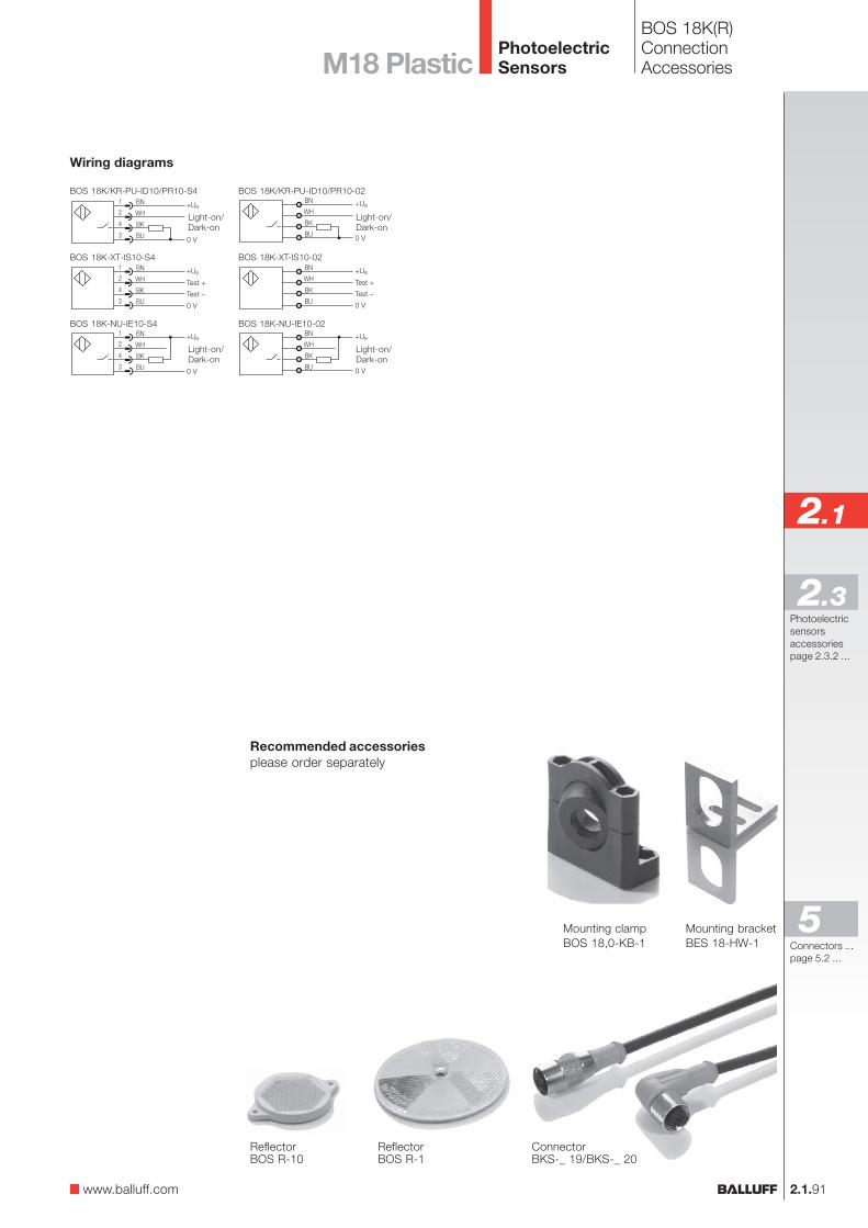
2.1.91
2.1
Photoelectricsensorsaccessoriespage 2.3.2 ...
2.3
www.balluff.com
M18 Plastic
Mounting clampBOS 18,0-KB-1
Mounting bracketBES 18-HW-1
ConnectorBKS-_ 19/BKS-_ 20
Wiring diagrams
BOS 18K/KR-PU-ID10/PR10-S4
BOS 18K-XT-IS10-S4
ReflectorBOS R-1
Recommended accessoriesplease order separately
BOS 18K(R)ConnectionAccessories
ReflectorBOS R-10
Light-on/Dark-on
Light-on/Dark-on
Light-on/Dark-on
Light-on/Dark-on
BOS 18K-NU-IE10-S4
BOS 18K/KR-PU-ID10/PR10-02
BOS 18K-XT-IS10-02
BOS 18K-NU-IE10-02
Connectors ...page 5.2 ...
5
PhotoelectricSensors
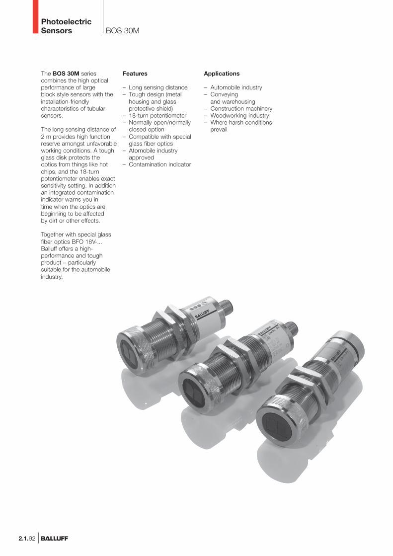
2.1.92
BOS 30M
The BOS 30M seriescombines the high opticalperformance of largeblock style sensors with theinstallation-friendlycharacteristics of tubularsensors.
The long sensing distance of2 m provides high functionreserve amongst unfavorableworking conditions. A toughglass disk protects theoptics from things like hotchips, and the 18-turnpotentiometer enables exactsensitivity setting. In additionan integrated contaminationindicator warns you intime when the optics arebeginning to be affectedby dirt or other effects.
Together with special glassfiber optics BFO 18V-...Balluff offers a high-performance and toughproduct – particularlysuitable for the automobileindustry.
Features
– Long sensing distance– Tough design (metal
housing and glassprotective shield)
– 18-turn potentiometer– Normally open/normally
closed option– Compatible with special
glass fiber optics– Atomobile industry
approved– Contamination indicator
Applications
– Automobile industry– Conveying
and warehousing– Construction machinery– Woodworking industry– Where harsh conditions
prevail
PhotoelectricSensors
2.1.93
2.1
Photoelectricsensorsaccessoriespage 2.3.2 ...
2.3
BOS 30MProduct OverviewM30 metal
Type
DiffuseBOS 30M-PU-1PH-SA -CBOS 30M-PU-1PH-SA3-CBOS 30M-GA-1PH-S4-C
OutputLighttype
Sensingdistance
0...2 m0...2 m0...2 m
Connec-tion
100 Hz100 Hz100 Hz
Outputfunction
Page
2.1.942.1.942.1.94
Red
ligh
t
Infra
red
M12
con
nect
or, 4
-pin
BK
S-S
1, 5
-pin
10...
30 V
DC
NP
N-T
rans
isto
r
PN
P-T
rans
isto
r
Ligh
t-on
Dar
k-on
UBSwitchingfrequency
www.balluff.com
Connectors ...page 5.2 ...
5
PhotoelectricSensors
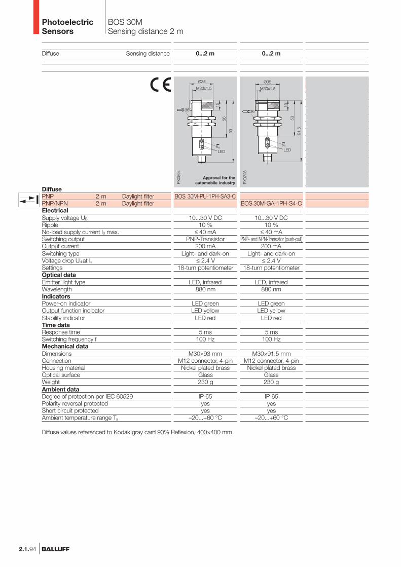
2.1.94
BOS 30MSensing distance 2 m
Diffuse Sensing distance
DiffusePNP 2 m Daylight filterPNP/NPN 2 m Daylight filterElectricalSupply voltage UB
RippleNo-load supply current I0 max.Switching outputOutput currentSwitching typeVoltage drop Ud at IeSettingsOptical dataEmitter, light typeWavelengthIndicatorsPower-on indicatorOutput function indicatorStability indicatorTime dataResponse timeSwitching frequency fMechanical dataDimensionsConnectionHousing materialOptical surfaceWeightAmbient dataDegree of protection per IEC 60529Polarity reversal protectedShort circuit protectedAmbient temperature range Ta
0...2 m
BOS 30M-GA-1PH-S4-C
10...30 V DC10 %
≤ 40 mAPNP- and NPN-Transistor (push-pull)
200 mALight- and dark-on
≤ 2.4 V18-turn potentiometer
LED, infrared880 nm
LED greenLED yellow
LED red
5 ms100 Hz
M30×91.5 mmM12 connector, 4-pinNickel plated brass
Glass230 g
IP 65yesyes
–20...+60 °C
Approval for theautomobile industry
Diffuse values referenced to Kodak gray card 90% Reflexion, 400×400 mm.
0...2 m
BOS 30M-PU-1PH-SA3-C
10...30 V DC10 %
≤ 40 mAPNP-Transistor
200 mALight- and dark-on
≤ 2.4 V18-turn potentiometer
LED, infrared880 nm
LED greenLED yellow
LED red
5 ms100 Hz
M30×93 mmM12 connector, 4-pinNickel plated brass
Glass230 g
IP 65yesyes
–20...+60 °C
PhotoelectricSensors
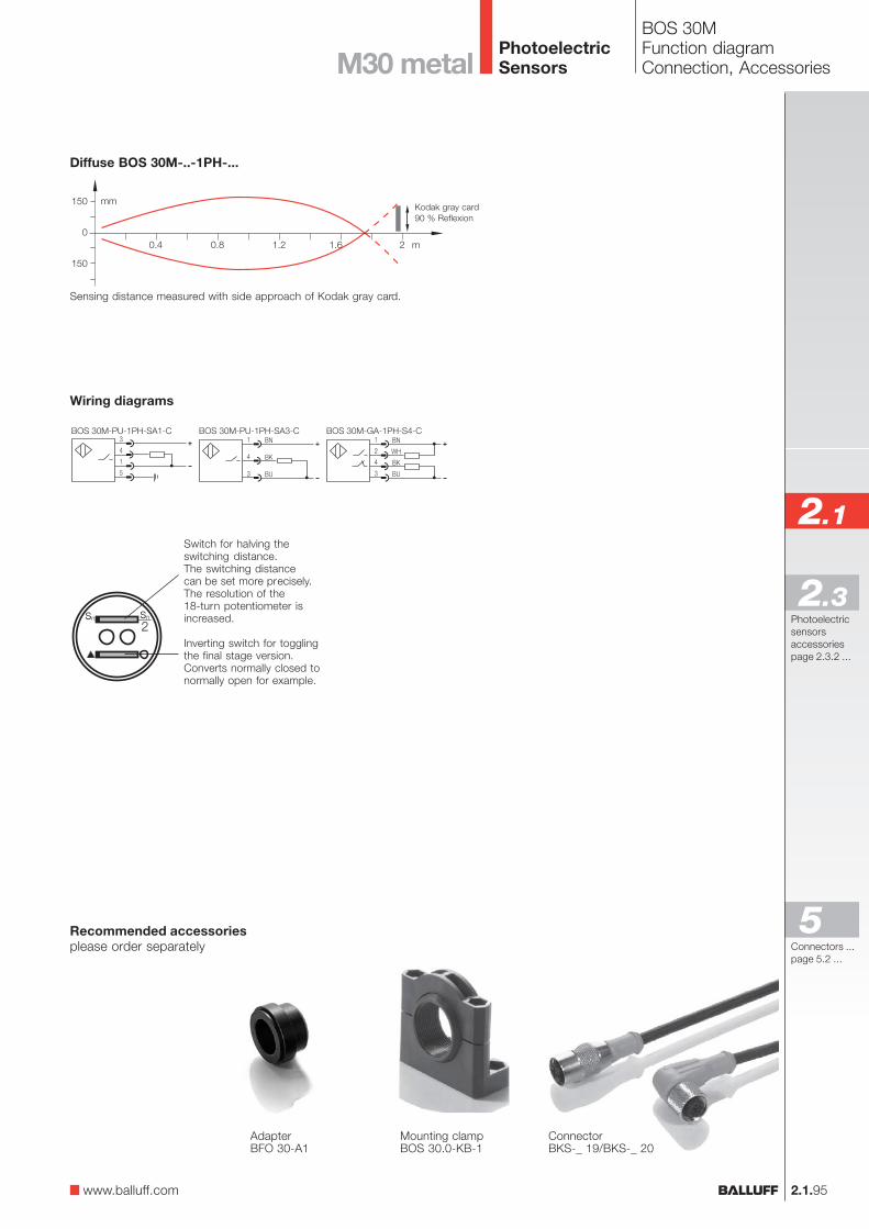
2.1.95
2.1
Photoelectricsensorsaccessoriespage 2.3.2 ...
2.3
BOS 30MFunction diagramConnection, AccessoriesM30 metal
Sensing distance measured with side approach of Kodak gray card.
Kodak gray card90 % Reflexion
Diffuse BOS 30M-..-1PH-...
Wiring diagrams
Recommended accessoriesplease order separately
ConnectorBKS-_ 19/BKS-_ 20
Mounting clampBOS 30.0-KB-1
AdapterBFO 30-A1
Switch for halving theswitching distance.The switching distancecan be set more precisely.The resolution of the18-turn potentiometer isincreased.
Inverting switch for togglingthe final stage version.Converts normally closed tonormally open for example.
www.balluff.com
Connectors ...page 5.2 ...
5
PhotoelectricSensors