CONTENTs3.amazonaws.com/machinetools_production/uploads/467948/... · CONTENT BORING MODuLAR...
56
BORING 103 www.parlec.com | 1-800-866-5872 | BORING CONTENT MODULAR TOOLHOLDING Collet Chucks & Morse Tapers......... 146 End Mill & Shell Mill Holders .......... 147 TECHNICAL INFORMATION Operating Instructions Twin Cutter ....................... 148 Balanced Cutting .................. 149 Stepped Cutting ................... 150 Recommended Roughing Speeds .................. 151 Rough Boring Feed Rates & Machining Allowance.............. 152 Rough Boring Chip Formation ......... 153 Operating Instructions Finish Boring ................. 154-155 Finish Boring Speeds ............... 156 Finish Boring Feeds ................ 157 QUOTATION REQUEST SHEET ............... 189 SELECTION GUIDE System Overview .................. 105 PC Connection .................... 106 Small Diameter & Finish Boring ....... 107 Rough Boring Head Systems .......... 108 Large Diameter Boring System .... 109-111 Insert Information .............. 112-115 COMMON COMPONENTS Modular Shanks Shanks ...................... 116-120 Ring Holders & Adapters ............. 121 Modular Components Extensions ....................... 122 Reductions & PC Screws............. 123 PRECISION FINISH BORING Small Diameter Boring Boring Heads ................. 124-125 Boring Bars. . . . . . . . . . . . . . . . . . . 126-127 Inserts ...................... 128-129 Large Diameter Boring Boring Heads (Inch & Metric) ..... 130-131 Boring Heads (Large Diameter) . . . 132-133 Insert Holders & Blanks ......... 134-135 Inserts .......................... 136 Components ...................... 137 TWIN BORE ROUGHING Boring Heads - .95” to 6.00” ......... 138 Boring Heads- 6.00” to 8.27” ......... 139 Boring Heads - 5.94” to 21.89” ....... 140 Insert Holders ..................... 141 Inserts ...................... 142-144 Components ...................... 145
Transcript of CONTENTs3.amazonaws.com/machinetools_production/uploads/467948/... · CONTENT BORING MODuLAR...
BORING
103
www.parlec.com | 1-800-866-5872 |
BORINGCONTENT
MODuLAR TOOLHOLDINGCollet Chucks & Morse Tapers . . . . . . . . . 146End Mill & Shell Mill Holders . . . . . . . . . . 147
TecHNIcAL INfORMATIONOperating Instructions Twin Cutter . . . . . . . . . . . . . . . . . . . . . . . 148Balanced Cutting . . . . . . . . . . . . . . . . . . 149Stepped Cutting . . . . . . . . . . . . . . . . . . . 150Recommended Roughing Speeds . . . . . . . . . . . . . . . . . . 151Rough Boring Feed Rates & Machining Allowance . . . . . . . . . . . . . . 152Rough Boring Chip Formation . . . . . . . . . 153
Operating Instructions Finish Boring . . . . . . . . . . . . . . . . . 154-155Finish Boring Speeds . . . . . . . . . . . . . . . 156Finish Boring Feeds . . . . . . . . . . . . . . . . 157
QuOTATION ReQueST SHeeT . . . . . . . . . . . . . . . 189
SeLecTION GuIDe System Overview . . . . . . . . . . . . . . . . . . 105PC Connection . . . . . . . . . . . . . . . . . . . . 106Small Diameter & Finish Boring . . . . . . . 107Rough Boring Head Systems . . . . . . . . . . 108Large Diameter Boring System . . . . 109-111Insert Information . . . . . . . . . . . . . . 112-115
cOMMON cOMPONeNTSModular ShanksShanks . . . . . . . . . . . . . . . . . . . . . . 116-120Ring Holders & Adapters . . . . . . . . . . . . . 121
Modular ComponentsExtensions . . . . . . . . . . . . . . . . . . . . . . . 122Reductions & PC Screws . . . . . . . . . . . . . 123
PRecISION fINISH BORINGSmall Diameter BoringBoring Heads . . . . . . . . . . . . . . . . . 124-125Boring Bars. . . . . . . . . . . . . . . . . . . 126-127Inserts . . . . . . . . . . . . . . . . . . . . . . 128-129
Large Diameter BoringBoring Heads (Inch & Metric) . . . . . 130-131Boring Heads (Large Diameter) . . . 132-133Insert Holders & Blanks . . . . . . . . . 134-135Inserts . . . . . . . . . . . . . . . . . . . . . . . . . . 136Components . . . . . . . . . . . . . . . . . . . . . . 137
TwIN BORe ROuGHINGBoring Heads - .95” to 6.00” . . . . . . . . . 138Boring Heads- 6.00” to 8.27” . . . . . . . . . 139Boring Heads - 5.94” to 21.89” . . . . . . . 140Insert Holders . . . . . . . . . . . . . . . . . . . . . 141Inserts . . . . . . . . . . . . . . . . . . . . . . 142-144Components . . . . . . . . . . . . . . . . . . . . . . 145
Boring
On size, on location, on the money!
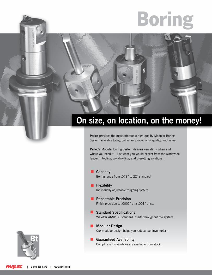
Parlec provides the most affordable high-quality Modular Boring System available today, delivering productivity, quality, and value.
Parlec’s Modular Boring System delivers versatility when and where you need it – just what you would expect from the worldwide leader in tooling, workholding, and presetting solutions.
CapacityBoring range from .078” to 22” standard.
FlexibilityIndividually adjustable roughing system.
Repeatable PrecisionFinish precision to .0001” at a .001” price.
Standard SpecificationsWe offer ANSI/ISO standard inserts throughout the system.
Modular DesignOur modular design helps you reduce tool inventories.
Guaranteed AvailabilityComplicated assemblies are available from stock.
| 1-800-866-5872 | www.parlec.com

105
BORINGBORING
www.parlec.com | 1-800-866-5872 |
System Overview
Selection Guide
SMALL DIAMETER BORING(Pages 124-129)
PRECISION FINISH BORING(Pages 124-137)
MODULAR HOLDERS(Pages 146-147)
LARGE DIAMETER BORING(Pages 132-133, 139-140)
BORING RING ADAPTERS(Pages 121)
SHANKS(Pages 116-120)
EXTENSIONS & REDUCTIONS(Pages 122-123)
INSERTS
BORING
106
BORI
NG
| 1-800-866-5872 | www.parlec.com
PC Connection
Selection Guide
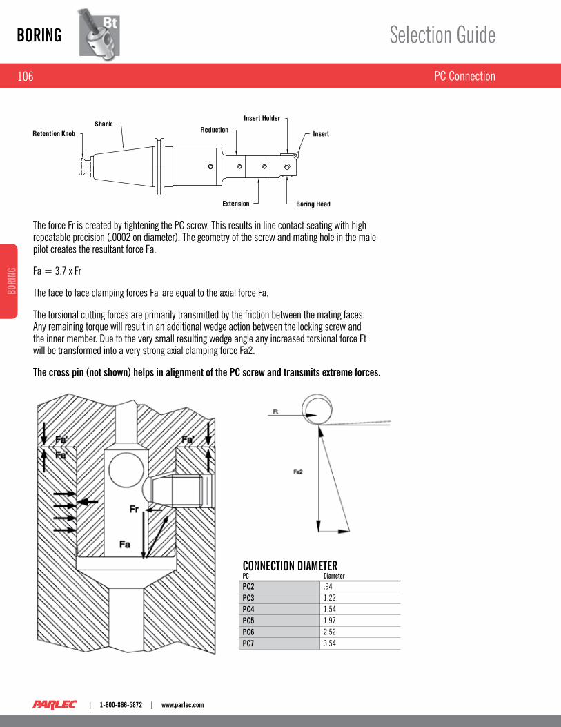
The force Fr is created by tightening the PC screw . This results in line contact seating with high repeatable precision ( .0002 on diameter) . The geometry of the screw and mating hole in the male pilot creates the resultant force Fa .
Fa = 3 .7 x Fr
The face to face clamping forces Fa' are equal to the axial force Fa .
The torsional cutting forces are primarily transmitted by the friction between the mating faces . Any remaining torque will result in an additional wedge action between the locking screw and the inner member . Due to the very small resulting wedge angle any increased torsional force Ft will be transformed into a very strong axial clamping force Fa2 .
The cross pin (not shown) helps in alignment of the PC screw and transmits extreme forces.
CONNECTION dIaMETERpC diameterPC2 .94PC3 1 .22PC4 1 .54PC5 1 .97PC6 2 .52PC7 3 .54
107
BORINGBORING
www.parlec.com | 1-800-866-5872 |
Small Diameter & Finish Boring Systems
Selection Guide
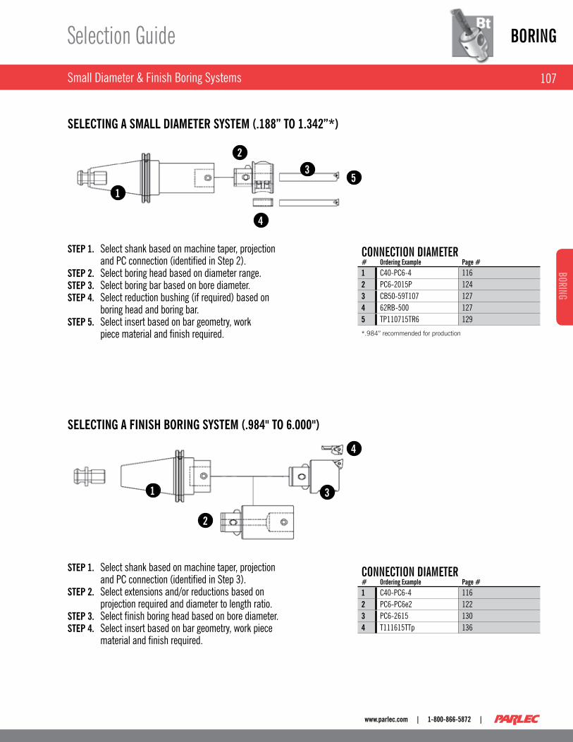
STEP 1. Select shank based on machine taper, projection and PC connection (identified in Step 2) . STEP 2. Select boring head based on diameter range . STEP 3. Select boring bar based on bore diameter . STEP 4. Select reduction bushing (if required) based on boring head and boring bar . STEP 5. Select insert based on bar geometry, work piece material and finish required .
SELECTING A SMALL DIAMETER SySTEM (.188” TO 1.342”*)
SELECTING A FINISH BORING SySTEM (.984" TO 6.000")
STEP 1. Select shank based on machine taper, projection and PC connection (identified in Step 3) . STEP 2. Select extensions and/or reductions based on projection required and diameter to length ratio . STEP 3. Select finish boring head based on bore diameter . STEP 4. Select insert based on bar geometry, work piece material and finish required .
1
1
2
3
4
23
4
5
CONNECTION dIaMETER# Ordering Example page #1 C40-PC6-4 1162 PC6-2015P 1243 CB50-59T107 1274 62RB-500 1275 TP110715TR6 129
*.984” recommended for production
CONNECTION dIaMETER# Ordering Example page #1 C40-PC6-4 1162 PC6-PC6e2 1223 PC6-2615 1304 T111615TTp 136

BORING
108
BORI
NG
| 1-800-866-5872 | www.parlec.com
Rough Boring Head Systems
Selection Guide
SELECTING A ROUGH BORING SySTEM (.984" TO 6.000")
SELECTING A ROUGH AND FINISH SySTEM (5.95" TO 8.27"*)
1
1
2
3
2
3
4
5
STEP 1. Select shank based on machine taper, projection and PC connection (identified in Step 3) . STEP 2. Select extensions and/or reductions based on projection required and diameter to length ratio . STEP 3. Select boring head based on boring range . STEP 4. Select insert holder pair based on geometry and diameter range . STEP 5. Select insert based on bar geometry, work piece material and finish required .
STEP 1. Select shank (PC6 size) based on machine taper and projection required . STEP 2. Select PC6-7108 . STEP 3. Select boring components using Steps 4-7 on following page .
CONNECTION dIaMETER# Ordering Example page #1 C50-PC6-4 1162 PC6-PCAR1 1233 PC4-4405 1454 4405-41C09 1415 C091615TTP(2) 143
CONNECTION dIaMETER# Ordering Example page #1 C50-PC6-4 1162 PC6-7108 132, 1393 7100-2816 133

109
BORINGBORING
www.parlec.com | 1-800-866-5872 |
Large Diameter Boring System
Selection Guide
SELECTING A LARGE DIAMETER SySTEM (ABOVE 6" 152.4MM)
Standard boring Ring Adapter(pg . 121)
Extension(pg . 122)
Finish Boring Head(pg . 133)
Modular Shank (pg . 116-120)
Modular Flange (pg . 121)
Insert Holder Base [pair] (pg . 140)
Insert Holder Base (pg . 141)
Counterweight for use with Finish Boring Unit (pg . 133)
Extension Base (pg . 133, 140)
Optional Finish Boring Unit (pg . 133)
1
2 34
5
6
7
STEP 1. Select taper shank or boring ring holder based on machine taper and bore projection . STEP 2. Select extension and/or modular flange based on taper and/or projection required . STEP 3. Select extension base based on bore diameter . STEP 4. Select finish head or roughing system . STEP 5. Rough boring only . Select rough insert holder based on insert geometry and bore diameter . STEP 6. Select finish boring head (recommended) or optional finish boring unit (use when counterbalance is required) . STEP 7. Select insert based on insert holder, work-piece material and finish .

BORING
110
BORI
NG
| 1-800-866-5872 | www.parlec.com
Large Diameter Boring System
Selection Guide
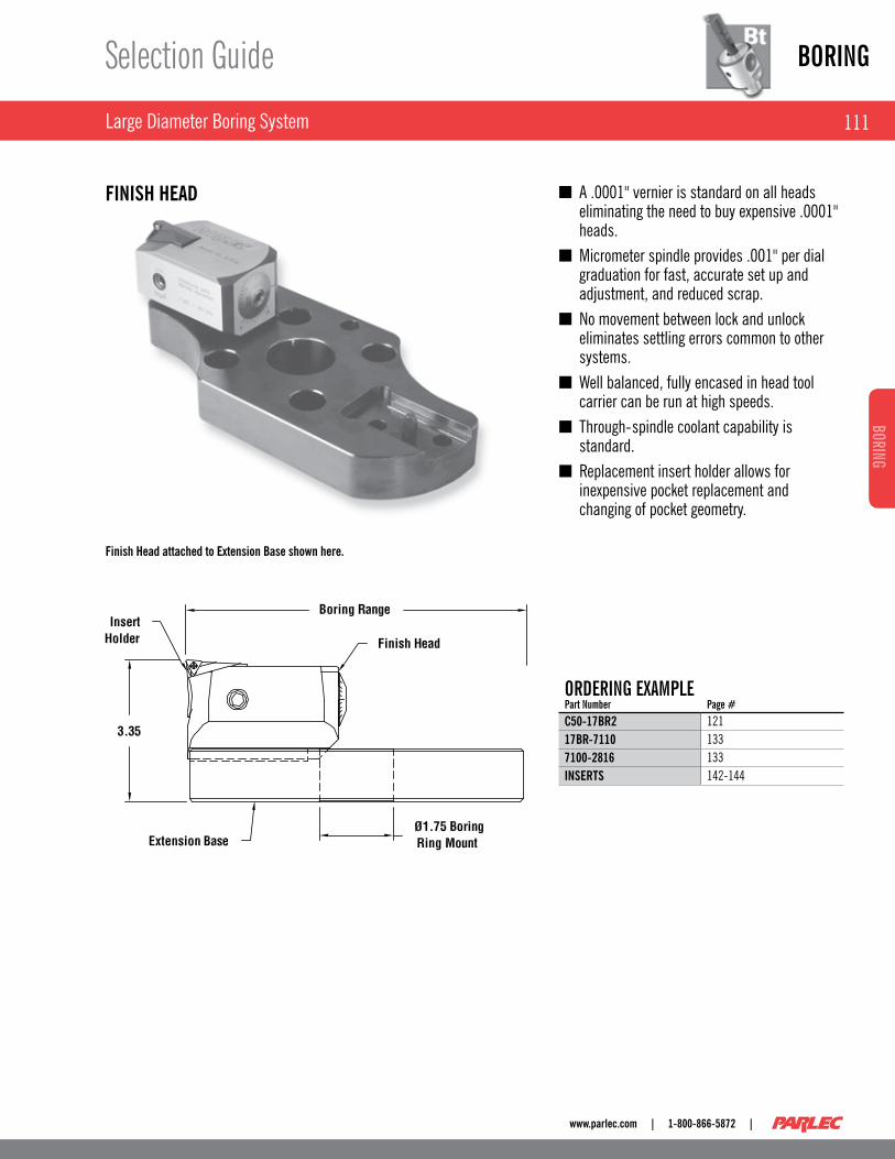
Independent height and diameter setting ■permit balanced cutting resulting in almost perfectly round holes from the beginning, irrespective of core shifts .Two height balanceable cutting edges with ■metal removal at rates almost 4 times that of a single cutter .Height adjustments are made with a cam ■that supports the insert holder where needed, at the furthest radial point .Each insert holder can be adjusted ■individually in diameter with a dial screw for fast, easy set-up operations .Balanced or stepped cutting can be done ■with the same set of insert holders permitting heavy stock removal and eliminating the need to purchase two sets of insert holders .ISO standard inserts eliminates the need for ■special expensive inserts .Mounting flange provides two orientation ■positions at 90° to one another, thus eliminating the need to purchase special components to clear the tool chain .
Extension Base 17BR-7112 shown here with insert holders.
ORdERING ExaMplEpart Number page #C50-17BR2 12117BR-7110 1407100-B460 1405605-61C12 141INSERTS 142-144
ROUGH BORING UNITS
111
BORINGBORING
www.parlec.com | 1-800-866-5872 |
Large Diameter Boring System
Selection Guide
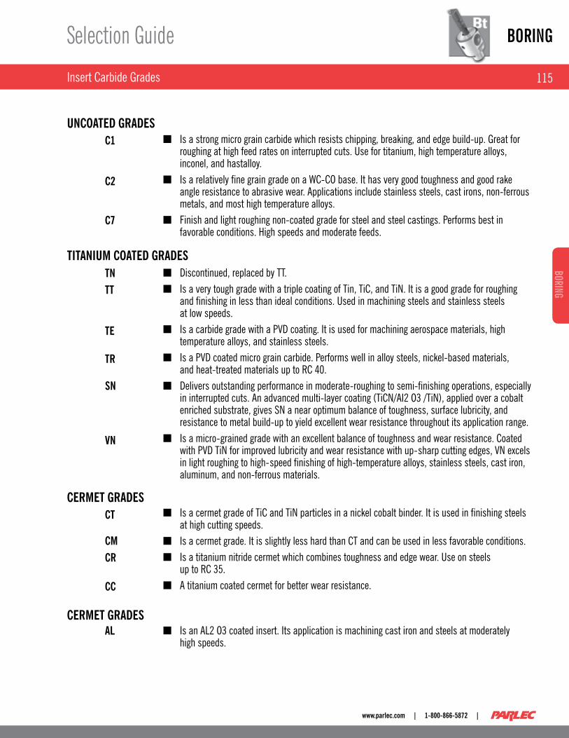
Finish Head attached to Extension Base shown here.
A .0001" vernier is standard on all heads ■eliminating the need to buy expensive .0001" heads .Micrometer spindle provides .001" per dial ■graduation for fast, accurate set up and adjustment, and reduced scrap .No movement between lock and unlock ■eliminates settling errors common to other systems .Well balanced, fully encased in head tool ■carrier can be run at high speeds .Through-spindle coolant capability is ■standard .Replacement insert holder allows for ■inexpensive pocket replacement and changing of pocket geometry .
ORdERING ExaMplEpart Number page #C50-17BR2 12117BR-7110 1337100-2816 133INSERTS 142-144
FINISH HEAD

BORING
112
BORI
NG
| 1-800-866-5872 | www.parlec.com
Inserts Information
Selection Guide
SHAPE:
SqUARE 80° DIAMOND TRIANGLE TRIGONFor rough boring ■through holes and castings to avoid exit hole breakout .Four usable edges for ■maximum insert life .
For rough boring to ■a shoulder or deep bore depths where maximum rigidity of the bar is required .For finishing small ■diameters where maximum edge strength is required .
For finishing with ■three corners for maximum insert life .
For rough boring ■when large depth of cut is required or when extreme core shift is experienced .
CARBIDE GRADE:Select the proper insert grade from pages 114-115 . Material type, machine capabilities and type of hole, i .e ., Interrupted Cut, can affect the grade of carbide used .
CoatedLonger service life at higher speeds . ■
UncoatedLess expensive and effective in materials for which coatings do not add any benefit . ■
CermetYields the highest speed and durability for selected materials . ■
RADIUS:Finish, bar rigidity, insert life, and engineering features of the workpiece all contribute to choosing the proper insert radius .Larger
Better surface finish and longer insert life . ■
SmallerLess cutting pressures, in extreme conditions, reduced bar flex and chatter . ■
PERIPHERy:Pressed
Utility grade for general purpose . Longer tool life . ■
GroundBetter for finishing where tight bore tolerances are required . ■

113
BORINGBORING
www.parlec.com | 1-800-866-5872 |
Inserts
Selection Guide
WARNING
DIAGRAM DESCRIPTION
PART NUMBER EXPLANATION
EXAMPLE: T111615TNP
The use of carbide in cutting is generally a safe and reasonable practice . When used properly, these products are designed to be safe and without risk to health and property . Please review the recommended use and pay particular attention to insure the tooling is used within its designed speed ranged and operating forces . Misuse may represent a hazard to people and property .
These products use materials which are classified as hazardous by OSHA . This may include one or more of the following carbide, titanium carbide, chromium carbide, chromium cadmium, cobalt, and nickel .
Carbide is a material which is brittle in nature . It will fracture from shock or impact which may cause pieces to detach at high velocities . Carbides should not be hammered or fitted with undo force . Suitable eye protection should be worn during all processes .
Carbide grinding may release dangerous levels of cobalt . Conventional precautions related to the operations of safe grinding should always be observed .
Additional information and material safety data sheets are available on request .
T 11 16 15 TN P
(T) size (11) Radius (16) Rake angle (15) Grade (TN) periphery (p)T=TRIANgULAR 05,06,09,11 08= .008 00=0° See Carbide -S=SqUARE 09,12 12= .016 06=6° grade P=PressedC=80° DIAMOND 05,06,09,12 06= .016 15=15° Section g=groundW=TRIgON 03,04,05,08 31= .031 20=20° Pages -- - 47= .047 23=23° 114-115 -

BORING
114
BORI
NG
| 1-800-866-5872 | www.parlec.com
Insert Carbide grades
Selection Guide
115
BORINGBORING
www.parlec.com | 1-800-866-5872 |
Insert Carbide grades
Selection Guide
Is a strong micro grain carbide which resists chipping, breaking, and edge build-up . great for ■roughing at high feed rates on interrupted cuts . Use for titanium, high temperature alloys, inconel, and hastalloy .Is a relatively fine grain grade on a WC-CO base . It has very good toughness and good rake ■angle resistance to abrasive wear . Applications include stainless steels, cast irons, non-ferrous metals, and most high temperature alloys .Finish and light roughing non-coated grade for steel and steel castings . Performs best in ■favorable conditions . High speeds and moderate feeds .
Discontinued, replaced by TT . ■
Is a very tough grade with a triple coating of Tin, TiC, and TiN . It is a good grade for roughing ■and finishing in less than ideal conditions . Used in machining steels and stainless steels at low speeds .Is a carbide grade with a PVD coating . It is used for machining aerospace materials, high ■temperature alloys, and stainless steels .Is a PVD coated micro grain carbide . Performs well in alloy steels, nickel-based materials, ■and heat-treated materials up to RC 40 .Delivers outstanding performance in moderate-roughing to semi-finishing operations, especially ■in interrupted cuts . An advanced multi-layer coating (TiCN/AI2 O3 /TiN), applied over a cobalt enriched substrate, gives SN a near optimum balance of toughness, surface lubricity, and resistance to metal build-up to yield excellent wear resistance throughout its application range .Is a micro-grained grade with an excellent balance of toughness and wear resistance . Coated ■with PVD TiN for improved lubricity and wear resistance with up-sharp cutting edges, VN excels in light roughing to high-speed finishing of high-temperature alloys, stainless steels, cast iron, aluminum, and non-ferrous materials .
Is a cermet grade of TiC and TiN particles in a nickel cobalt binder . It is used in finishing steels ■at high cutting speeds .Is a cermet grade . It is slightly less hard than CT and can be used in less favorable conditions . ■
Is a titanium nitride cermet which combines toughness and edge wear . Use on steels ■up to RC 35 .A titanium coated cermet for better wear resistance . ■
Is an AL2 O3 coated insert . Its application is machining cast iron and steels at moderately ■high speeds .
UNCOATED GRADES
TITANIUM COATED GRADES
CERMET GRADES
CERMET GRADES
C1
C2
C7
TNTT
TE
TR
SN
VN
CT
CMCR
CC
AL

Modular ShanksBORING
116
BORI
NG
| 1-800-866-5872 | www.parlec.com
V-Flange Shanks
40 TapERpart Number Connection size Flange Coolant*** B C d l p* Weight (lbs.)C40-PC2-2 PC2 - .944 2 .07 2 .00 .56 3 .54 2 .4C40-PC2-3 PC2 - .944 3 .33 3 .15 1 .95 4 .80 2 .5C40-PC2-4 PC2 - .944 4 .11 3 .94 2 .74 5 .59 2 .6C40-PC3-3 PC3 - 1 .22 3 .15 3 .20 1 .78 4 .76 2 .6C40-PC3-5 PC3 - 1 .22 5 .12 5 .57 3 .74 6 .73 3 .3C40-PC4-1 PC4 - 1 .75 1 .38 1 .75 - 3 .23 2 .2C40-PC4-3 PC4 C40B-PC4-3 1 .54 2 .87 3 .15 1 .50 4 .72 2 .7C40-PC4-6 PC4 - 1 .54 6 .02 6 .30 4 .26 7 .87 4 .3C40-PC5-3 PC5 - 1 .97 2 .48 3 .15 1 .11 4 .72 2 .8C40-PC5-6 PC5 - 1 .97 5 .63 6 .30 4 .26 7 .87 5 .5C40-PC6-3** PC6 C40B-PC6-3 2 .52 2 .00 3 .42 .63 4 .80 3 .1C40-PC6-4 PC6 C40B-PC6-4 2 .52 2 .72 3 .94 1 .34 5 .51 3 .3C40-PC6-6 PC6 - 2 .52 5 .08 6 .30 3 .70 7 .87 6 .3
Order Retention Knob separately (see pages 98-100) .
50 Taper C50-PC6-6 shown here.
50 TapERpart Number Connection size Flange Coolant*** B C d l p* Weight (lbs.)C50-PC2-2 PC2 - .94 2 .07 2 .00 .56 3 .54 7 .0C50-PC2-4 PC2 - .94 4 .11 3 .94 2 .74 5 .59 7 .0C50-PC2-5 PC2 - .94 5 .29 5 .12 3 .92 6 .77 7 .3C50-PC3-4 PC3 - 1 .22 3 .94 4 .39 2 .56 5 .55 7 .7C50-PC3-5 PC3 - 1 .22 5 .12 5 .57 3 .74 6 .73 7 .7C50-PC3-6 PC3 - 1 .22 6 .30 6 .13 4 .30 7 .91 8 .1C50-PC4-4 PC4 C50B-PC4-4 1 .54 3 .61 3 .94 2 .24 5 .46 7 .6C50-PC4-6 PC4 - 1 .54 6 .02 6 .30 4 .65 7 .87 8 .7C50-PC4-8 PC4 - 1 .54 7 .60 7 .88 6 .22 9 .45 9 .5C50-PC5-4 PC5 - 1 .97 3 .27 3 .94 1 .89 5 .51 7 .8C50-PC5-6 PC5 - 1 .97 5 .63 6 .30 4 .26 7 .87 9 .7C50-PC5-8 PC5 - 1 .97 7 .20 7 .88 5 .83 9 .45 10 .9C50-PC5-10 PC5 - 1 .97 9 .57 10 .24 8 .19 11 .81 12 .8C50-PC6-4 PC6 C50B-PC6-4 2 .52 2 .72 3 .94 1 .34 5 .51 7 .7C50-PC6-6 PC6 - 2 .52 5 .08 6 .30 3 .70 7 .87 10 .8C50-PC6-8 PC6 - 2 .52 6 .65 7 .88 5 .28 9 .45 12 .8C50-PC6-10 PC6 - 2 .52 9 .02 10 .24 7 .64 11 .81 15 .9C50-PC6-12 PC6 - 2 .52 11 .38 12 .60 10 .00 14 .17 19 .1C50-PC7-6 PC7 - 3 .54 3 .27 6 .30 1 .89 7 .87 10 .0C50-PC7-8 PC7 - 3 .54 5 .27 8 .30 3 .89 9 .87 15 .3C50-PC7-10 PC7 - 3 .54 7 .20 10 .24 5 .83 11 .81 20 .3
60 TapERpart Number Connection size B C d l p* Weight (lbs.)C60-PC6-4 PC6 2 .52 3 .10 4 .20 1 .60 5 .90 22 .6C60-PC6-12 PC6 2 .52 11 .10 12 .20 9 .60 13 .90 34 .0C60-PC7-10 PC7 3 .54 7 .30 10 .22 5 .80 11 .91 35 .2
Part numbers in bold face are in-stock items * Compute “P” dimensions by adding “C” dimensions of all components used. Maximum bore depth “D” may be increased by using extension adapters. *** Other sizes available on request.

Modular Shanks
DIN-69871 Shanks, Form ADB 117
BORINGBORING
www.parlec.com | 1-800-866-5872 |
Form B Coolant can be closed with a screw for through spindle coolant applications.
dIN 40 TapERpart Number Connection size p* B C l d Weight (lbs.)D40-PC2-80 PC2 4 .72 .94 3 .34 1 .93 3 .15 2 .4D40-PC3-80 PC3 4 .72 1 .22 3 .15 1 .77 3 .19 2 .6D40-PC4-50 PC4 3 .23 1 .54 1 .38 - 1 .85 2 .2D40-PC4-80 PC4 4 .72 1 .54 2 .87 1 .50 3 .15 2 .8D40-PC4-160 PC4 7 .87 1 .54 6 .02 4 .25 6 .30 4 .4D40-PC5-80 PC5 4 .72 1 .97 2 .48 1 .10 3 .15 2 .8D40-PC6-80 PC6 4 .80 2 .52 2 .00 0 .63 3 .43 3 .0D40-PC6-100 PC6 5 .51 2 .52 2 .72 1 .34 3 .94 3 .3D40-PC6-160 PC6 7 .87 2 .52 5 .08 3 .70 6 .30 6 .4
dIN 50 TapERpart Number Connection size p* B C l d Weight (lbs.)D50-PC2-100 PC2 5 .51 .94 4 .09 2 .76 3 .94 7 .0D50-PC2-130 PC2 6 .69 .94 5 .27 3 .90 5 .12 7 .2D50-PC3-110 PC3 5 .51 1 .22 3 .94 2 .56 4 .37 7 .7D50-PC3-160 PC3 7 .87 1 .22 6 .30 4 .29 5 .91 8 .1D50-PC4-100 PC4 5 .51 1 .54 3 .58 2 .20 3 .94 7 .7D50-PC4-160 PC4 7 .87 1 .54 6 .02 4 .65 6 .30 8 .8D50-PC4-200 PC4 9 .45 1 .54 7 .60 6 .22 7 .87 9 .5D50-PC5-100 PC5 5 .51 1 .97 3 .27 1 .89 3 .94 7 .7D50-PC5-160 PC5 7 .87 1 .97 5 .63 4 .25 6 .30 9 .7D50-PC6-100 PC6 5 .51 2 .52 2 .71 1 .34 3 .94 7 .7D50-PC6-160 PC6 7 .87 2 .52 5 .08 3 .70 6 .30 10 .8D50-PC6-200 PC6 9 .45 2 .52 6 .65 5 .28 7 .87 12 .8D50-PC6-260 PC6 11 .81 2 .52 9 .01 7 .64 10 .24 15 .8D50-PC6-320 PC6 14 .17 2 .52 11 .37 10 .00 12 .60 19 .2
Part numbers in bold face are in-stock items * Compute “P” dimension by adding “C” dimensions of all components used. Maximum bore depth “D” may be increased by using extension adapters. *** Other sizes available on request.
Modular ShanksBORING
118
BORI
NG
| 1-800-866-5872 | www.parlec.com
BT Shanks
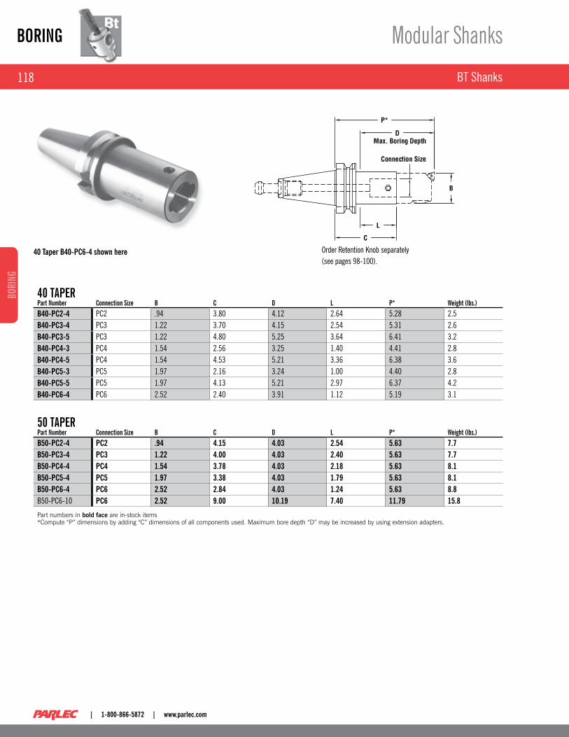
Order Retention Knob separately (see pages 98-100) .
40 Taper B40-PC6-4 shown here
40 TapERpart Number Connection size B C d l p* Weight (lbs.)B40-PC2-4 PC2 .94 3 .80 4 .12 2 .64 5 .28 2 .5B40-PC3-4 PC3 1 .22 3 .70 4 .15 2 .54 5 .31 2 .6B40-PC3-5 PC3 1 .22 4 .80 5 .25 3 .64 6 .41 3 .2B40-PC4-3 PC4 1 .54 2 .56 3 .25 1 .40 4 .41 2 .8B40-PC4-5 PC4 1 .54 4 .53 5 .21 3 .36 6 .38 3 .6B40-PC5-3 PC5 1 .97 2 .16 3 .24 1 .00 4 .40 2 .8B40-PC5-5 PC5 1 .97 4 .13 5 .21 2 .97 6 .37 4 .2B40-PC6-4 PC6 2 .52 2 .40 3 .91 1 .12 5 .19 3 .1
50 TapERpart Number Connection size B C d l p* Weight (lbs.)B50-PC2-4 PC2 .94 4.15 4.03 2.54 5.63 7.7B50-PC3-4 PC3 1.22 4.00 4.03 2.40 5.63 7.7B50-PC4-4 PC4 1.54 3.78 4.03 2.18 5.63 8.1B50-PC5-4 PC5 1.97 3.38 4.03 1.79 5.63 8.1B50-PC6-4 PC6 2.52 2.84 4.03 1.24 5.63 8.8B50-PC6-10 PC6 2.52 9.00 10.19 7.40 11.79 15.8
Part numbers in bold face are in-stock items *Compute “P” dimensions by adding “C” dimensions of all components used. Maximum bore depth “D” may be increased by using extension adapters.
Modular Shanks
119
BORINGBORING
www.parlec.com | 1-800-866-5872 |
HSK Shanks
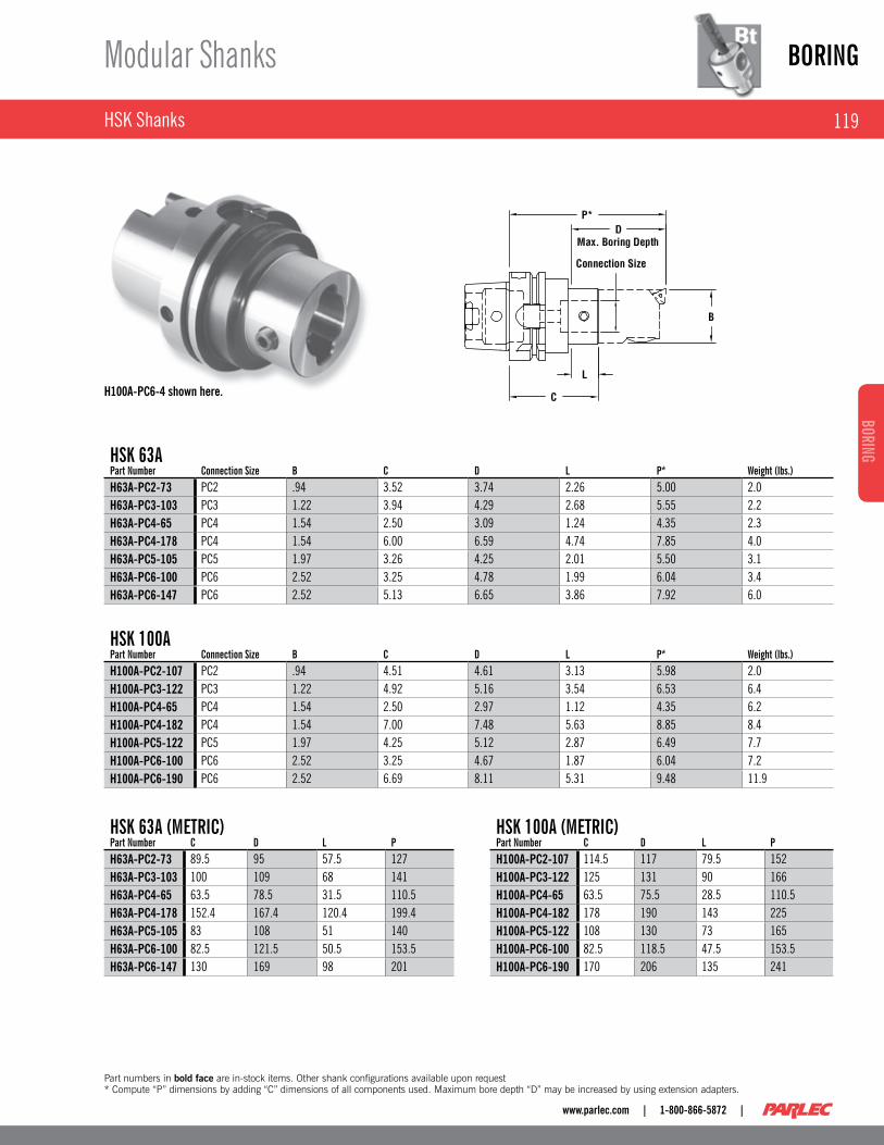
H100A-PC6-4 shown here.
hsK 63apart Number Connection size B C d l p* Weight (lbs.)H63A-PC2-73 PC2 .94 3 .52 3 .74 2 .26 5 .00 2 .0H63A-PC3-103 PC3 1 .22 3 .94 4 .29 2 .68 5 .55 2 .2H63A-PC4-65 PC4 1 .54 2 .50 3 .09 1 .24 4 .35 2 .3H63A-PC4-178 PC4 1 .54 6 .00 6 .59 4 .74 7 .85 4 .0H63A-PC5-105 PC5 1 .97 3 .26 4 .25 2 .01 5 .50 3 .1H63A-PC6-100 PC6 2 .52 3 .25 4 .78 1 .99 6 .04 3 .4H63A-PC6-147 PC6 2 .52 5 .13 6 .65 3 .86 7 .92 6 .0
hsK 100apart Number Connection size B C d l p* Weight (lbs.)H100A-PC2-107 PC2 .94 4 .51 4 .61 3 .13 5 .98 2 .0H100A-PC3-122 PC3 1 .22 4 .92 5 .16 3 .54 6 .53 6 .4H100A-PC4-65 PC4 1 .54 2 .50 2 .97 1 .12 4 .35 6 .2H100A-PC4-182 PC4 1 .54 7 .00 7 .48 5 .63 8 .85 8 .4H100A-PC5-122 PC5 1 .97 4 .25 5 .12 2 .87 6 .49 7 .7H100A-PC6-100 PC6 2 .52 3 .25 4 .67 1 .87 6 .04 7 .2H100A-PC6-190 PC6 2 .52 6 .69 8 .11 5 .31 9 .48 11 .9
hsK 63a (METRIC)part Number C d l pH63A-PC2-73 89 .5 95 57 .5 127H63A-PC3-103 100 109 68 141H63A-PC4-65 63 .5 78 .5 31 .5 110 .5H63A-PC4-178 152 .4 167 .4 120 .4 199 .4H63A-PC5-105 83 108 51 140H63A-PC6-100 82 .5 121 .5 50 .5 153 .5H63A-PC6-147 130 169 98 201
hsK 100a (METRIC)part Number C d l pH100A-PC2-107 114 .5 117 79 .5 152H100A-PC3-122 125 131 90 166H100A-PC4-65 63 .5 75 .5 28 .5 110 .5H100A-PC4-182 178 190 143 225H100A-PC5-122 108 130 73 165H100A-PC6-100 82 .5 118 .5 47 .5 153 .5H100A-PC6-190 170 206 135 241
Part numbers in bold face are in-stock items. Other shank configurations available upon request * Compute “P” dimensions by adding “C” dimensions of all components used. Maximum bore depth “D” may be increased by using extension adapters.

BORING
120
BORI
NG
| 1-800-866-5872 | www.parlec.com
NMTB Shanks & Straight Shanks
Modular Shanks
40 Taper N40-PC4-3 shown here.
S20-PC6-4 shown here.
30 TapERpart Number Connection size B C d l p* Weight (lbs.)N30-PC4-4 PC4 1 .54 2 .64 3 .94 1 .82 4 .49 1 .5
40 TapERpart Number Connection size B C d l p* Weight (lbs.)N40-PC4-3 PC4 1 .54 1 .93 3 .20 1 .35 3 .78 2 .1N40-PC6-4 PC6 2 .52 2 .17 4 .14 1 .34 4 .97 6 .4
50 TapERpart Number Connection size B C d l p* Weight (lbs.)N50-PC4-4 PC4 1 .54 2 .87 3 .94 2 .09 4 .72 6 .4N50-PC4-6 PC4 1 .54 5 .24 6 .30 4 .45 7 .09 7 .6N50-PC5-4 PC5 1 .97 2 .48 3 .94 1 .70 4 .72 6 .6N50-PC5-8 PC5 1 .97 6 .42 7 .88 5 .63 8 .66 10 .6N50-PC6-4 PC6 2 .52 1 .93 3 .94 1 .15 4 .72 6 .4N50-PC6-8 PC6 2 .52 5 .86 7 .88 5 .08 8 .65 12 .9N50-PC6-12 PC6 2 .52 10 .59 12 .60 9 .81 13 .38 17 .8N50-PC7-6 PC7 3 .54 2 .48 5 .87 1 .26 7 .09 8 .1
sTRaIGhT shaNKspart Number Connection size a B C d l p* Weight (lbs.)S12-PC4-3 PC4 1 .25 1 .54 2 .00 3 .75 1 .90 3 .85 2 .0S20-PC4-3 PC4 2 .00 1 .54 2 .00 3 .75 1 .90 3 .85 4 .2S12-PC6-4 PC6 1 .25 2 .52 2 .00 4 .70 1 .90 4 .80 3 .1S20-PC6-4 PC6 2 .00 2 .52 2 .00 4 .70 1 .90 4 .80 5 .2
Part numbers in bold face are in-stock items. *Compute “P” dimensions by adding “C” dimensions of all components used. Maximum bore depth “D” may be increased by using extension adapters. **For Weldon flats, add “W” after SXX, i.e., S12W-PC4-3. Other shank configurations available on request.

121
BORINGBORING
www.parlec.com | 1-800-866-5872 |
Large Diameter Boring System – Ring Holders
Modular Shanks
BORING RING adapTERspart Number a (dia.) B (dia.) C E G Thread No. of Threads Weight (lbs.)C50-17BR2* 1 .750 4 .94 2 .50 4 .00 .250 1/2-13 4 13 .7C50-17BR5* 1 .750 4 .94 5 .00 4 .00 .250 1/2-13 4 21 .9N50-17BR2 1 .750 4 .94 2 .00 4 .00 .250 1/2-13 4 12 .1
Part numbers in bold face are in-stock items. *Includes 90° tool tip orientation for clearance of oversize boring tools in carousels.
MOdulaR BORING RING hOldERspart Number pC Connection Weight (lbs.)PC6-17BR2 PC6 6 .5PC7-17BR2 PC7 7 .1
Order Retention Knob Separately(see pages 98-100)
MODULAR BORING RING HOLDERS
BORING RING ADAPTERS
Integral shank for non-modular applications . ■
Boring Ring HolderPC7-17BR2 shown here.
Boring Ring Holder PC7-17BR2 shown here.

BORING
122
BORI
NG
| 1-800-866-5872 | www.parlec.com
Extensions
Modular Components
EXTENSIONS
HEAVy METAL EXTENSIONS*
ExTENsIONspart Number Connection size B C Weight (lbs.)PC2-PC2E1 PC2 .94 1 .18 .3PC2-PC2E2 PC2 .94 1 .77 .4PC3-PC3E1 PC3 1 .22 1 .18 .4PC3-PC3E2 PC3 1 .22 1 .77 .5PC4-PC4E1 PC4 1 .54 1 .57 .8PC4-PC4E2 PC4 1 .54 2 .36 1 .1PC5-PC5E2 PC5 1 .97 2 .36 1 .9PC5-PC5E3 PC5 1 .97 3 .54 2 .8PC6-PC6E2 PC6 2 .52 2 .36 3 .0PC6-PC6E4 PC6 2 .52 3 .94 5 .0PC7-PC7E4 PC7 3 .54 3 .94 9 .9PC7-PC7E6 PC7 3 .54 6 .30 17 .0
Extension PC4-PC4E1 shown here.
Heavy Metal Extension PC4-150HM15 shown here.
hEavy METal ExTENsIONspart Number Connection size B C Weight (lbs.)PC2-094HM11 PC2 .937 11 .42 3 .9PC3-125HM14 PC3 1 .250 13 .78 9 .0PC4-150HM15 PC4 1 .500 14 .75 13 .0Part numbers in bold face are in-stock items. *Not reccomended for use on lathes with twin bore units. Consult Parlec’s Applications department.

123
BORINGBORING
www.parlec.com | 1-800-866-5872 |
REduCTIONspart Number a (Connection) E (Connection) B1 C d l (Max.) M (Min.) p* Weight B2PC3-PC2R1 PC3 PC2 1 .22 1 .36 2 .36 .965 .39 2 .83 .4 .945PC4-PC2R2 PC4 PC2 1 .54 2 .03 2 .95 1 .56 .47 3 .50 .6 .945PC4-PC3R2 PC4 PC3 1 .54 1 .85 2 .95 1 .38 .47 3 .46 1 .0 1 .220PC5-PC2R2 PC5 PC2 1 .97 2 .03 2 .76 1 .36 .67 3 .50 .8 .945PC5-PC2R3 PC5 PC2 1 .97 3 .21 3 .94 2 .54 .67 4 .69 1 .1 .945PC5-PC3R1 PC5 PC3 1 .97 1 .85 2 .76 1 .18 .67 3 .46 1 .0 1 .220PC5-PC3R3 PC5 PC3 1 .97 3 .03 3 .94 2 .36 .67 4 .65 1 .3 1 .220PC5-PC4R1 PC5 PC4 1 .97 1 .57 2 .76 .91 .67 3 .43 1 .1 1 .535PC5-PC4R2 PC5 PC4 1 .97 2 .76 3 .94 2 .09 .67 3 .61 1 .6 1 .535PC6-PC2R2 PC6 PC2 2 .52 2 .38 3 .15 1 .75 .63 3 .85 1 .5 .945PC6-PC2R3 PC6 PC2 2 .52 3 .76 4 .53 3 .13 .63 5 .24 1 .8 .945PC6-PC3R2 PC6 PC3 2 .52 2 .20 3 .15 1 .58 .63 3 .82 1 .7 1 .220PC6-PC3R3 PC6 PC3 2 .52 3 .58 4 .53 2 .95 .63 5 .20 2 .1 1 .220PC6-PC3R5 PC6 PC3 2 .52 5 .35 6 .30 4 .72 .63 6 .97 2 .6 1 .220PC6-PC4R1 PC6 PC4 2 .52 1 .93 3 .15 1 .30 .63 3 .78 1 .7 1 .535PC6-PC4R3 PC6 PC4 2 .52 3 .31 4 .53 2 .68 .63 5 .16 1 .3 1 .535PC6-PC4R5 PC6 PC4 2 .52 5 .08 6 .30 4 .45 .63 6 .93 3 .0 1 .535PC6-PC5R1 PC6 PC5 2 .52 1 .54 3 .15 .91 .63 3 .78 1 .8 1 .969PC6-PC5R3 PC6 PC5 2 .52 2 .91 4 .53 2 .28 .63 5 .16 2 .8 1 .969PC6-PC5R4 PC6 PC5 2 .52 4 .69 6 .30 4 .06 .63 6 .93 4 .1 1 .969PC7-PC6R4 PC7 PC6 3 .54 4 .18 6 .30 3 .50 .70 6 .97 7 .0 2 .52
Reductions & PC Screws
Modular Components
PC SCREWS
Reduction PC60PC4R3 shown here.
PC Screw 880-006 shown here.
pC sCREWspart Number Connection size Wrench Tightening Torque880-002 PC2 018-102 25 IN . LBS .880-003 PC3 018-103 42 IN . LBS .880-004 PC4 018-104 84 IN . LBS .880-005 PC5 018-105 168 IN . LBS .880-006 PC6 018-106 336 IN . LBS .880-007 PC7 018-107 840 IN . LBS .
Part numbers in bold face are in-stock items. *Compute “P” dimensions by adding “C” dimensions of all components used. Maximum bore depth “D” may be increased by using extension adapters.

BORING
124
BORI
NG
| 1-800-866-5872 | www.parlec.com
Small Diameter Boring .078” to 1 .342” (2mm to 34mm)
Precision Finish Boring
A .0001" vernier is standard on all heads eliminating the need to ■purchase expensive .0001" heads .Micrometer spindle provides .001" per dial graduation for fast, ■accurate set-up and adjustment, and reduced scrap .No movement between lock and unlock eliminates setting errors ■common to other systems .Well balanced, fully encased in head tool carrier can be run at ■high speeds .Bored-through tool receiver (TR only) allows the boring tool to be ■telescoped for optimum rigidity .All system components with through-hole permits through-spindle ■coolant .
SMALL DIAMETER BORING HEADS FOR TOOL ROOM OR PRODUCTION
PC6-2015TR shown here.
Vernier Scale with reference marks. (See page 145).
Recommended up to .984 for production
INCh GRaduaTEd uNITs (.001” Per dial graduation with .0001” Vernier)part Number Bore Range Min. Bore Range Max. Connection size a B C Radial adjust. Weight (lbs.)PC4-2015 .078 .790 PC4 .500 2 .00 1 .50 .100 1 .0PC6-2015P .078 .984 PC6 .625 2 .52 1 .65 .100 2 .8PC6-2015TR .078 1 .342 PC6 .625 2 .52 1 .65 .312 2 .4
METRIC GRaduaTEd uNITs (.02mm Per dial graduation with .002mm Vernier)part Number Bore Range Min. Bore Range Max. Connection size a B C Radial adjust. Weight (lbs.)PC4-2005 2 20 PC4 12 .7 50 .8 38 .1 2 .5 1 .0PC4-201205 2 20 PC4 12 50 .8 38 .1 2 .5 .5PC6-2005P 2 25 PC6 15 .875 64 42 2 .5 2 .8PC6-2005TR 2 34 PC6 15 .875 64 42 7 .92 2 .4PC6-201605 2 34 PC6 16 64 42 7 .92 2 .4
Part numbers in bold face are in-stock items. *Range can be extended by using boring bars not available in this catalog. To establish maximum diameter for each boring bar: Boring bar minimum diameter +2x adjustment.

125
BORINGBORING
www.parlec.com | 1-800-866-5872 |
Small Diameter Boring Screw, Pins & Wrenches
Precision Finish Boring
SMALL DIAMETER BORING HEAD
Wrench 018-105 shown here.
Vernier Scale Side
Clamp Screw Side
Slide LockScrew Side
Oil side
sMall dIaMETER BORING hEadpart Number Boring Bar holder screw slide lock screw Wrench pC pinPC4-2015 029-517 029-018 018-105 PCP-004PC6-2015 (X) 029-089 029-089 018-105 PCP-S06
Part numbers in bold face are in-stock items.
BORING
126
BORI
NG
| 1-800-866-5872 | www.parlec.com
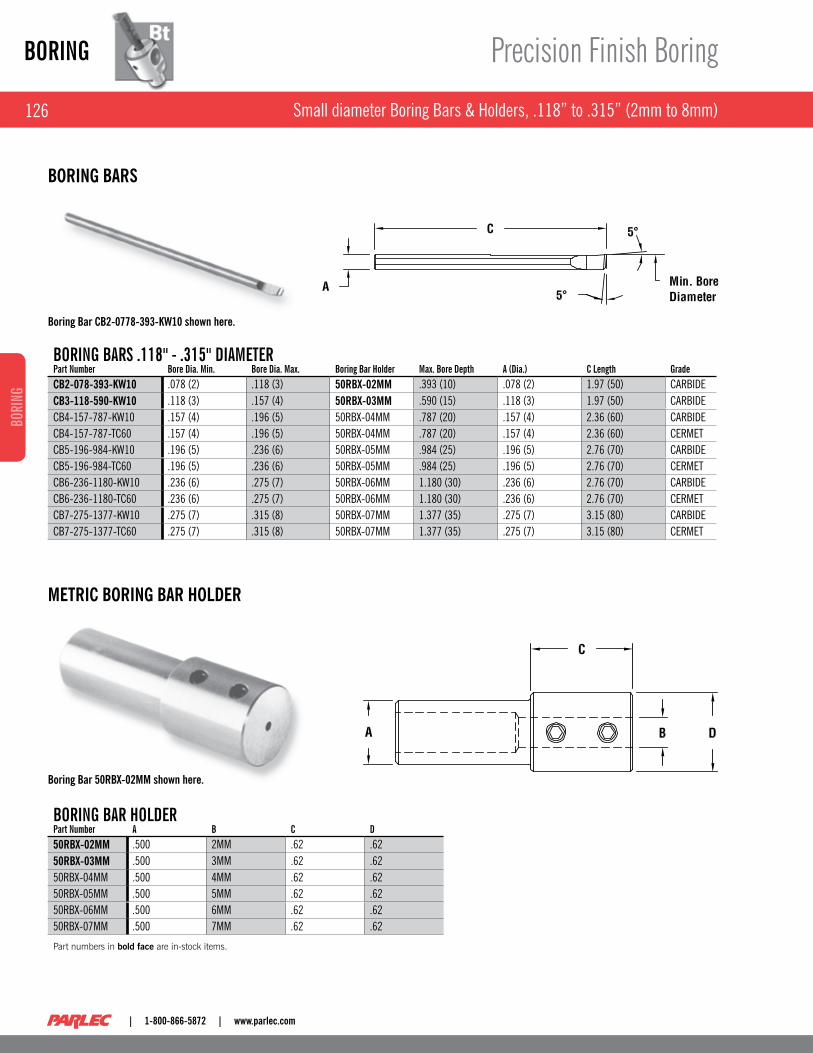
Small diameter Boring Bars & Holders, .118” to .315” (2mm to 8mm)
Precision Finish Boring
BORING BaRs .118" - .315" dIaMETERpart Number Bore dia. Min. Bore dia. Max. Boring Bar holder Max. Bore depth a (dia.) C length GradeCB2-078-393-KW10 .078 (2) .118 (3) 50RBX-02MM .393 (10) .078 (2) 1 .97 (50) CARBIDECB3-118-590-KW10 .118 (3) .157 (4) 50RBX-03MM .590 (15) .118 (3) 1 .97 (50) CARBIDECB4-157-787-KW10 .157 (4) .196 (5) 50RBX-04MM .787 (20) .157 (4) 2 .36 (60) CARBIDECB4-157-787-TC60 .157 (4) .196 (5) 50RBX-04MM .787 (20) .157 (4) 2 .36 (60) CERMETCB5-196-984-KW10 .196 (5) .236 (6) 50RBX-05MM .984 (25) .196 (5) 2 .76 (70) CARBIDECB5-196-984-TC60 .196 (5) .236 (6) 50RBX-05MM .984 (25) .196 (5) 2 .76 (70) CERMETCB6-236-1180-KW10 .236 (6) .275 (7) 50RBX-06MM 1 .180 (30) .236 (6) 2 .76 (70) CARBIDECB6-236-1180-TC60 .236 (6) .275 (7) 50RBX-06MM 1 .180 (30) .236 (6) 2 .76 (70) CERMETCB7-275-1377-KW10 .275 (7) .315 (8) 50RBX-07MM 1 .377 (35) .275 (7) 3 .15 (80) CARBIDECB7-275-1377-TC60 .275 (7) .315 (8) 50RBX-07MM 1 .377 (35) .275 (7) 3 .15 (80) CERMET
BORING BARS
METRIC BORING BAR HOLDER
Boring Bar CB2-0778-393-KW10 shown here.
Boring Bar 50RBX-02MM shown here.
BORING BaR hOldERpart Number a B C d50RBX-02MM .500 2MM .62 .6250RBX-03MM .500 3MM .62 .6250RBX-04MM .500 4MM .62 .6250RBX-05MM .500 5MM .62 .6250RBX-06MM .500 6MM .62 .6250RBX-07MM .500 7MM .62 .62
Part numbers in bold face are in-stock items.

127
BORINGBORING
www.parlec.com | 1-800-866-5872 |
Small Diameter Boring Bars & Bushings, .188” to 1 .000” (4 .78mm to 25 .4mm)
Precision Finish Boring
BORING BARS
REDUCTION BUSHINGS
Boring Bar SB37-43T105 shown here.
Reduction Bushing 62RB-250 shown here.
BORING BaRs .188" - 1.000" dIaMETERpart Number Coolant part Number
Bore dia. Min.
Bore dia. Max.
Reduction Bushing
Max. Bore depth a (dia.) C Bar Material
Insert Type/size Insert screw
Insert screw Wrench
CB15-18C056 CB15-18C056C .188 .218 XXRB-156 1 .50 .156 6 .00 CARBIDE CDCD 05 028-919 018-002SB18-18C052 – .188 .218 XXRB-187 .50 .187 2 .50 STEEL CDCD 05 028-919 018-002CB18-21C054 – .218 .232 XXRB-187 2 .00 .187 4 .00 CARBIDE CDCD 05 028-919 018-002SB18-23C052 – .232 .300 XXRB-187 1 .00 .187 2 .50 STEEL CDCD 05 028-919 018-002CB18-23CO54 CB18-23C054C .232 .300 XXRB-187 2 .00 .187 4 .00 CARBIDE CDCD 05 028-919 018-002SB18-28TO53 – .280 .300 XXRB-187 1 .00 .187 3 .50 STEEL TDAB 05 028-920 018-007CB18-29TO54 CB18-29T054C .290 .310 XXRB-187 2 .00 .187 4 .00 CARBIDE TDAB 05 028-920 018-007SB25-29CO53 – .290 .310 XXRB-250 1 .25 .250 3 .00 STEEL CDCD 05 028-919 018-002SB25-30TO54 – .300 .362 XXRB-250 1 .25 .250 4 .00 STEEL TDAB 05 028-920 018-007CB25-30CO54 CB25-30C054C .300 .362 XXRB-250 2 .50 .250 4 .00 CARBIDE CDCD 05 028-919 018-002CB25-31TO54 CB25-31T054C .310 .372 XXRB-250 2 .50 .250 4 .00 CARBIDE TDAB 05 028-920 018-007SB31-36T054 – .362 .430 XXRB-312 1 .75 .312 4 .00 STEEL TDAB 05 028-920 018-007CB31-37TO56 CB31-37TO56C .372 .440 XXRB-312 3 .25 .312 6 .00 CARBIDE TDAB 05 028-920 018-007SB37-43T105 SB37-43T105C .430 .580 XXRB-375 2 .00 .375 5 .00 STEEL TPgH 11 028-921 018-003CB37-44T107 CB37-44T107C .440 .590 XXRB-375 4 .00 .375 7 .00 CARBIDE TPgH 11 028-921 018-003SB50-58T106 SB50-58T106C .580 .717 XXRB-500 2 .50 .500 5 .00 STEEL TPgH 11 028-921 018-003CB50-59T107 CB50-59T107C .590 .717 XXRB-500 5 .00 .500 7 .00 CARBIDE TPgH 11 028-921 018-003SB62-71T117 SB62-71T117C .717 1 .000 – 3 .50 .625 7 .00 STEEL TPgH 11 028-921 018-003CB62-71T118 CB62-71T118C .717 1 .000 – 6 .00 .625 8 .00 CARBIDE TPgH 11 028-921 018-003– CB62-83T117C .83 1 .45 – 3 .50 .625 7 .00 CARBIDE TPgH 11 028-921 018-003– SB62-83T114C .83 1 .45 – 2 .50 .625 4 .00 STEEL TPgH 11 028-921 018-003
Part numbers in bold face are in-stock items. *Recommended for Production. For maximum range, see page 124. Minimum bore diameter above is based on a gage insert with .016” nose radius.
REduCTION BushINGspart Number a B C Weight (lbs.)50RB-156 .500 .156 1 .18 .150RB-187 .500 .187 1 .18 .150RB-250 .500 .250 1 .18 .150RB-312 .500 .312 1 .18 .150RB-375 .500 .375 1 .18 .162RB-08MM .625 8MM 1 .42 .162RB-10MM .625 10MM 1 .42 .162RB-12MM .625 12MM 1 .42 .162RB-156 .625 .156 1 .42 .162RB-187 .625 .187 1 .42 .162RB-219 .625 .219 1 .42 .162RB-250 .625 .250 1 .42 .162RB-312 .625 .312 1 .42 .162RB-375 .625 .375 1 .42 .162RB-438 .625 .438 1 .42 .162RB-500 .625 .500 1 .42 .1

BORING
128
BORI
NG
| 1-800-866-5872 | www.parlec.com
Small Diameter Boring Inserts – 80° Diamond
Precision Finish Boring
sIZE CdCd 05part Number IC Clearance angle R T Rake angle hd Grade Type peripheryC050700C1G .156 15° .007 .040 0° .084 C1 UNCOATED gROUNDC051600C1G .156 15° .016 .040 0° .084 C1 UNCOATED gROUNDC050700C2G .156 15° .007 .040 0° .084 C2 UNCOATED gROUNDC051600C2G .156 15° .016 .040 0° .084 C2 UNCOATED gROUNDC050700CRG .156 15° .007 .040 0° .084 CR CERMET gROUNDCO51600CRG .156 15° .016 .040 0° .084 CR CERMET gROUNDC050700TRG .156 15° .007 .040 0° .084 TR COATED gROUNDC051600TRG .156 15° .016 .040 0° .084 TR COATED gROUNDC050700ALg .156 15° .007 .040 0° .084 AL COATED gROUNDC051600ALG .156 15° .016 .040 0° .084 AL COATED gROUNDC050700PCD .156 15° .007 .040 0° .084 PCD DIAMOND gROUNDC051600PCD .156 15° .016 .040 0° .084 PCD DIAMOND gROUND
Part numbers in bold face are in-stock items.
At Parlec, the phrase “measurably better” isn’t just a slogan . It’s a commitment to you . Our philosophy of providing “measurably better” products to our customers guarantees that you will be able to meet all of your quality, cost and delivery requirements .
80° Diamond Insert C050700C1G shown here.
129
BORINGBORING
www.parlec.com | 1-800-866-5872 |
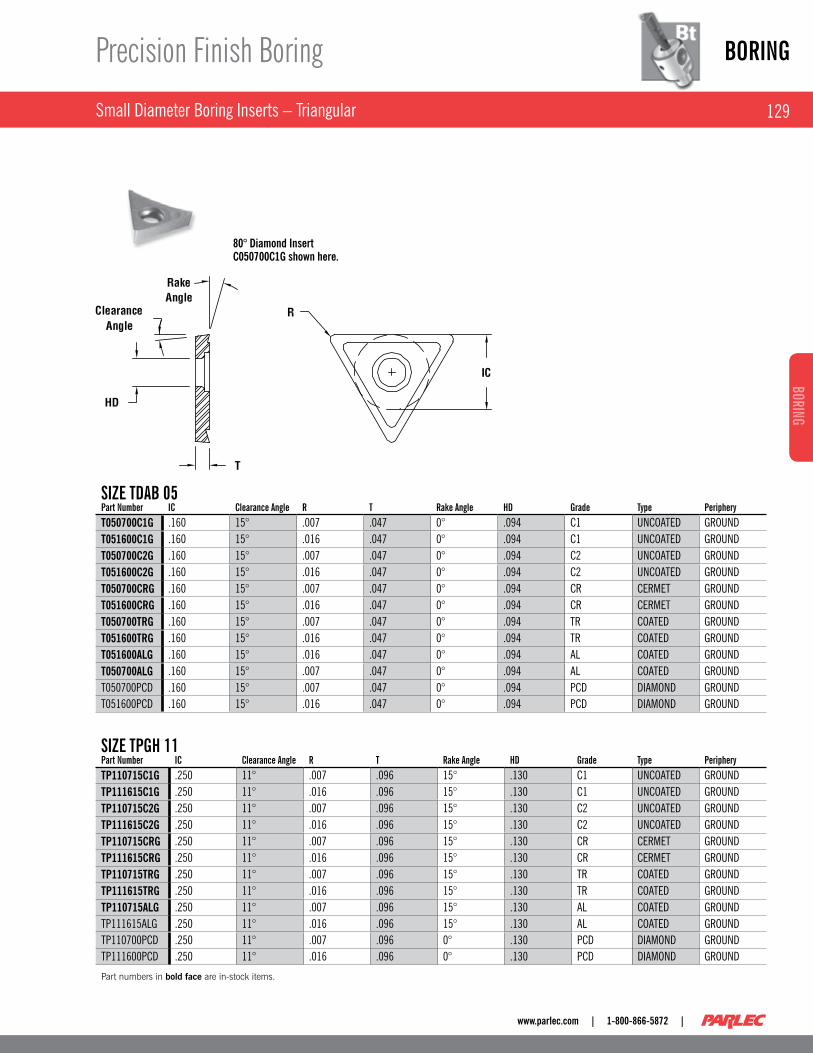
Small Diameter Boring Inserts – Triangular
Precision Finish Boring
80° Diamond Insert C050700C1G shown here.
sIZE TdaB 05part Number IC Clearance angle R T Rake angle hd Grade Type peripheryT050700C1G .160 15° .007 .047 0° .094 C1 UNCOATED gROUNDT051600C1G .160 15° .016 .047 0° .094 C1 UNCOATED gROUNDT050700C2G .160 15° .007 .047 0° .094 C2 UNCOATED gROUNDT051600C2G .160 15° .016 .047 0° .094 C2 UNCOATED gROUNDT050700CRG .160 15° .007 .047 0° .094 CR CERMET gROUNDT051600CRG .160 15° .016 .047 0° .094 CR CERMET gROUNDT050700TRG .160 15° .007 .047 0° .094 TR COATED gROUNDT051600TRG .160 15° .016 .047 0° .094 TR COATED gROUNDT051600ALG .160 15° .016 .047 0° .094 AL COATED gROUNDT050700ALG .160 15° .007 .047 0° .094 AL COATED gROUNDT050700PCD .160 15° .007 .047 0° .094 PCD DIAMOND gROUNDT051600PCD .160 15° .016 .047 0° .094 PCD DIAMOND gROUND
sIZE TpGh 11part Number IC Clearance angle R T Rake angle hd Grade Type peripheryTP110715C1G .250 11° .007 .096 15° .130 C1 UNCOATED gROUNDTP111615C1G .250 11° .016 .096 15° .130 C1 UNCOATED gROUNDTP110715C2G .250 11° .007 .096 15° .130 C2 UNCOATED gROUNDTP111615C2G .250 11° .016 .096 15° .130 C2 UNCOATED gROUNDTP110715CRG .250 11° .007 .096 15° .130 CR CERMET gROUNDTP111615CRG .250 11° .016 .096 15° .130 CR CERMET gROUNDTP110715TRG .250 11° .007 .096 15° .130 TR COATED gROUNDTP111615TRG .250 11° .016 .096 15° .130 TR COATED gROUNDTP110715ALG .250 11° .007 .096 15° .130 AL COATED gROUNDTP111615ALg .250 11° .016 .096 15° .130 AL COATED gROUNDTP110700PCD .250 11° .007 .096 0° .130 PCD DIAMOND gROUNDTP111600PCD .250 11° .016 .096 0° .130 PCD DIAMOND gROUND
Part numbers in bold face are in-stock items.

BORING
130
BORI
NG
| 1-800-866-5872 | www.parlec.com
.984” to 6 .00” (25mm to 152mm) Inch and Metric Boring Heads
Precision Finish Boring
Vernier Scale with Reference Marks . (See page 145)
Includes 3° Insert Holder . Order other styles separately (see page 131, 134 & 135)
A .0001" ( .002mm) vernier is standard on ■all heads eliminating the need to purchase expensive .0001" ( .002mm) heads .Micrometer spindle provides .001" ( .02mm) ■per dial graduation for fast, accurate set-up and adjustment, and reduced scrap .No movement between lock and unlock ■eliminates setting errors common to other systems .Well balanced, fully encased in head tool ■carrier can be run at high speeds .Through-spindle coolant capability is ■standard .Replacement insert holder allows for ■inexpensive pocket replacement and changing of pocket geometry .
PRECISION FINISH BORING HEADS WITH EXTENDED LENGTH INSERT HOLDERS
PC6-2615 Boring Head shown here.
sTaNdaRd INChpart Number Bore Range Min. Bore Range Max.
Insert holder size Connection size B (dia.) C
Insert holder screw
Insert Type and size Weight (lbs.)
PC2-2215 0 .984 1 .300 2 PC2 0 .925 1 .48 2215-01 TCMT 06** 0 .3PC3-2315 1 .240 1 .654 3 PC3 1 .201 1 .61 2315-01 TCMT 06** 0 .5PC4-2415 1 .614 2 .126 4 PC4 1 .496 1 .85 2415-01 TCMT 11 0 .9PC5-2515 2 .087 2 .756 5 PC5 1 .929 2 .24 2515-01 TCMT 11 1 .8PC6-2615 2 .677 4 .000 6 PC6 2 .480 2 .79 2615-01 TCMT 11 3 .9PC6-2616 3 .937 6 .000 7 PC6 3 .740 2 .79 2615-01 TCMT 11 6 .5PC7-2716 3 .937 6 .000 7 PC7 3 .740 3 .425 2615-01 TCMT 11 7 .5
sTaNdaRd METRICpart Number Bore Range Min. Bore Range Max. Connection size
Insert holder size B (dia.) C
Insert holder screw
Insert Type and size Weight (lbs.)
PC2-2205 25 33 PC2 2 23 .5 37 .5 2215-01 TCMT 06** 0 .3PC3-2305 32 42 PC3 3 30 .5 41 2315-01 TCMT 06** 0 .5PC4-2405 41 54 PC4 4 38 47 2415-01 TCMT 11 0 .9PC5-2505 53 70 PC5 5 49 57 2515-01 TCMT 11 1 .8PC6-2605 68 101 .5 PC6 6 63 71 2615-01 TCMT 11 3 .9PC6-2606 100 152 PC6 7 95 71 2615-01 TCMT 11 6 .5PC7-2706 100 152 PC7 7 95 87 2615-01 TCMT 11 7 .5
Part numbers in bold face are in-stock items. .001” per dial graduation with .0001” Vernier. *3° Insert Holders are standard and are included on Boring Head. Others are optional insert holders and are purchased separately, these are not recommended for dedicated production jobs. ** Note: Additional clearance required for nose radius above .016”.
131
BORINGBORING
www.parlec.com | 1-800-866-5872 |
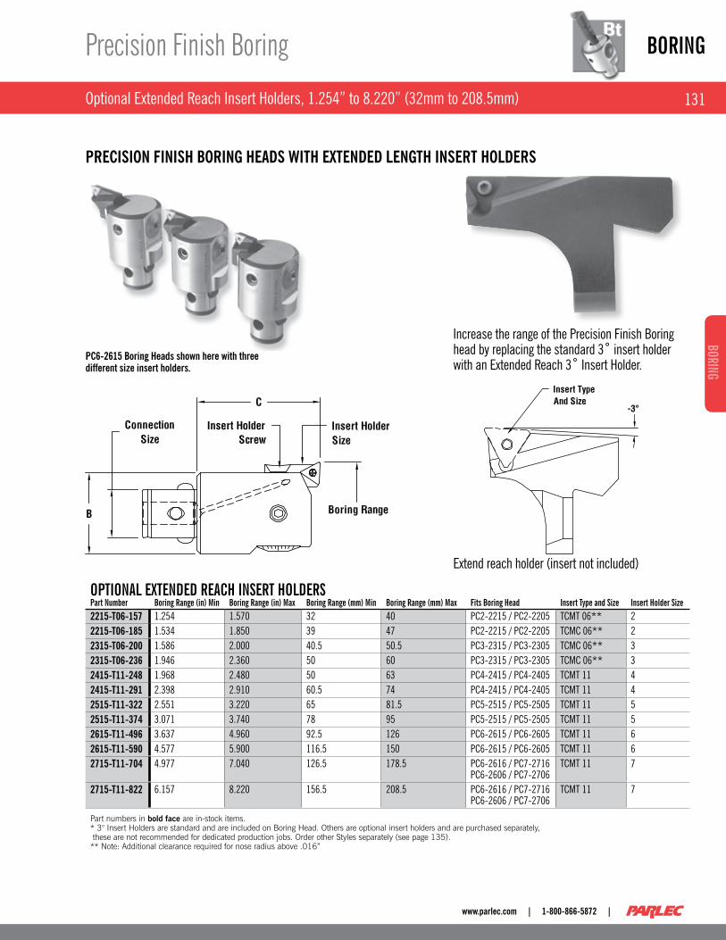
Optional Extended Reach Insert Holders, 1 .254” to 8 .220” (32mm to 208 .5mm)
Precision Finish Boring
PRECISION FINISH BORING HEADS WITH EXTENDED LENGTH INSERT HOLDERS
PC6-2615 Boring Heads shown here with three different size insert holders.
OpTIONal ExTENdEd REaCh INsERT hOldERspart Number Boring Range (in) Min Boring Range (in) Max Boring Range (mm) Min Boring Range (mm) Max Fits Boring head Insert Type and size Insert holder size2215-T06-157 1 .254 1 .570 32 40 PC2-2215 / PC2-2205 TCMT 06** 22215-T06-185 1 .534 1 .850 39 47 PC2-2215 / PC2-2205 TCMC 06** 22315-T06-200 1 .586 2 .000 40 .5 50 .5 PC3-2315 / PC3-2305 TCMC 06** 32315-T06-236 1 .946 2 .360 50 60 PC3-2315 / PC3-2305 TCMC 06** 32415-T11-248 1 .968 2 .480 50 63 PC4-2415 / PC4-2405 TCMT 11 42415-T11-291 2 .398 2 .910 60 .5 74 PC4-2415 / PC4-2405 TCMT 11 42515-T11-322 2 .551 3 .220 65 81 .5 PC5-2515 / PC5-2505 TCMT 11 52515-T11-374 3 .071 3 .740 78 95 PC5-2515 / PC5-2505 TCMT 11 52615-T11-496 3 .637 4 .960 92 .5 126 PC6-2615 / PC6-2605 TCMT 11 62615-T11-590 4 .577 5 .900 116 .5 150 PC6-2615 / PC6-2605 TCMT 11 62715-T11-704 4 .977 7 .040 126 .5 178 .5 PC6-2616 / PC7-2716
PC6-2606 / PC7-2706TCMT 11 7
2715-T11-822 6 .157 8 .220 156 .5 208 .5 PC6-2616 / PC7-2716 PC6-2606 / PC7-2706
TCMT 11 7
Part numbers in bold face are in-stock items. * 3° Insert Holders are standard and are included on Boring Head. Others are optional insert holders and are purchased separately, these are not recommended for dedicated production jobs. Order other Styles separately (see page 135). ** Note: Additional clearance required for nose radius above .016”
Increase the range of the Precision Finish Boring head by replacing the standard 3˚ insert holder with an Extended Reach 3˚ Insert Holder .
Extend reach holder (insert not included)

BORING
132
BORI
NG
| 1-800-866-5872 | www.parlec.com
5 .95” to 8 .27” (151mm to 210mm)
Precision Finish Boring
For use on 40 tapers with 15 lb . tool change limit . ■
Reduces inventory . ■
Interchangeable with other sizes . ■
Finish Assembly PC6-7108 shown here.
Finish Assembly with attached Finish Head shown here.
BORING RaNGE - INChEsBoring RangeMin. Max. Extension Base Extension Base Weight (lbs.) Boring head5.95 8.27 PC6-7108 7.1 7100-2816
BORING RaNGE - METRICBoring Range
Min. Max. Extension Base Extension Base Weight (lbs.) Boring head151.13 210.06 PC6-7108 7.1 7100-2806
Part numbers in bold face are in-stock items.

133
BORINGBORING
www.parlec.com | 1-800-866-5872 |
6 .00” to 21 .89” (152 .4mm to 556mm)
Precision Finish Boring
Finish bore full range of extension base . ■
Uses modular extension base to minimize tooling inventory . ■
Diameter adjustment of .0001 with Vernier scale . ■
.040 per revolution, .001 ( .02 mm) on diameter dial . ■
Extension Base with Finish Head shown here.
Note: For ordering example, see page 111
LARGE DIAMETER
BORING RaNGE - INChEsBoring RangeMin. Max. Extension Base Extension Base Weight (lbs.) Boring head5 .95 8 .27 17BR-7108 7 .1 7100-28168 .22 10 .54 17BR-7110 8 .8 7100-281610 .49 12 .81 17BR-7112 11 .1 7100-281612 .76 15 .08 17BR-7115 14 .2 7100-281615 .03 17 .35 17BR-7117 16 .5 7100-281617 .30 19 .62 17BR-7119 18 .8 7100-281619 .57 21 .89 17BR-7121 21 .9 7100-2816
alTERNaTE hEad WITh COuNTERWEIGhT*Finish head Base CounterweightFBU-2415 7100-B460 816-009
*Alternate Head w/Counterweight is compatible with all listed items in the “Inch - Boring Range” table.
alTERNaTE hEad WITh COuNTERWEIGhT*Finish head Base CounterweightFBU-2405 7100-B460 816-009
*Alternate Head w/Counterweight is compatible with all listed items in the “Metric - Boring Range” table.
BORING RaNGE - METRICBoring Range
Min. Max Extension Base Extension Base Weight (lbs.) Boring head151 .13 210 .06 17BR-7108 7 .1 7100-2806208 .79 267 .72 17BR-7110 8 .8 7100-2806266 .45 325 .37 17BR-7112 11 .1 7100-2806324 .10 383 .03 17BR-7115 14 .2 7100-2806381 .76 440 .69 17BR-7117 16 .5 7100-2806439 .42 498 .35 17BR-7119 18 .8 7100-2806497 .08 556 .01 17BR-7121 21 .9 7100-2806
BORING hEad INsERT sIZE & WEIGhTpart Number Insert Insert holder size Weight (lbs.)7100-2806 TCMT 11 8 4 .37100-2816 TCMT 11 8 4 .37100-B460 TCMT 11 - 2 .8816-009 TCMT 11 - .7FBU-2405 TCMT 11 4 .7FBU-2415 TCMT 11 4 .7
Part numbers in bold face are in-stock items.

BORING
134
BORI
NG
| 1-800-866-5872 | www.parlec.com
Insert Holders
Precision Finish Boring
Designed to allow boring into a corner . The -3° leads the insert into the ■workpiece with less tendency to deflect . Square shoulders, if required, are generally best produced utilizing the twin cutter with 0° lead insert holders during the roughing operation .
STyLE 1: 3° INSERT HOLDERS
STyLE 2: 0° LEAD INSERT HOLDERS
STyLE 3: 3° EXTENDED LEAD INSERT HOLDERS
Included with Finishing Head
sTylE 1part Number Insert holder size Insert Type and size Insert screw Insert screw Wrench2215-T06 2 TCMT 06 028-910 018-0022315-T06 3 TCMT 06 028-910 018-0022315-T11 3* TCMT 11 812-458 018-0072415-T11 4 TCMT 11 812-458 018-0072515-T11 5 TCMT 11 028-905 018-0072615-T11 6 TCMT 11 028-905 018-0072715-T11 7 TCMT 11 028-905 018-0072715-T16 7 TCMT 16 028-906 018-0082815-T11 8 TCMT 11 028-905 018-0072815-T16 8 TCMT 16 028-906 018-008
*Changes the "C" dimension on PC3-2315 to 1.69.
sTylE 2part Number Insert holder size Insert Type and size Insert screw Insert screw Wrench2210-T06 2 TCMT 06 028-910 018-0022310-T06 3 TCMT 06 028-910 018-0022410-T11 4 TCMT 11 812-458 018-0072510-T11 5 TCMT 11 028-905 018-0072610-T11 6 TCMT 11 028-905 018-0072710-T11 7 TCMT 11 028-905 018-007
sTylE 3part Number Insert holder size Insert Type and size Insert screw Insert screw Wrench2215-T06-157 2 TCMT 06 028-910 018-0022215-T06-185 2 TCMT 06 028-910 018-0022215-T06-200 3 TCMT 06 028-910 018-0022315-T06-236 3 TCMT 06 028-910 018-0022315-T11-248 4 TCMT 11 812-458 018-0072415-T11-291 4 TCMT 11 812-458 018-0072515-T11-322 5 TCMT 11 028-905 018-0072515-T11-374 5 TCMT 11 028-905 018-0072615-T11-374 6 TCMT 11 028-905 018-0072615-T11-590 6 TCMT 11 - 018-0072715-T11-704 7 TCMT 11 028-905 018-0072715-T11-822 7 TCMT 11 028-905 018-007
Part numbers in bold face are in-stock items. Order Inserts separately (see page 136).
Care should be taken in applying this insert holder . Finishing to a ■square shoulder results in increased tool pressure which can affect finish and size .

135
BORINGBORING
www.parlec.com | 1-800-866-5872 |
Precision Finish Boring
Insert Holder Blanks
Order Inserts, Insert Screws, and Wrenches Separately .
INsERT hOldER BlaNKspart Number Quantity size/Type a B C d Material Case hardened Recommendation2215-BLANK SINgLE 2 FINISH .300 .71 .35 .14 1018 RC 50-54/ .010 - .015 DEEP2315-BLANK SINgLE 3 FINISH .345 .78 .44 .18 1018 RC 50-54/ .010 - .015 DEEP2415-BLANK SINgLE 4 FINISH .440 1 .01 .57 .20 1018 RC 50-54/ .010 - .015 DEEP2515-BLANK SINgLE 5 FINISH .550 1 .21 .71 .30 1018 RC 50-54/ .010 - .015 DEEP2615-BLANK SINgLE 6 FINISH .710 1 .35 1 .00 .45 1018 RC 50-54/ .010 - .015 DEEP2715-BLANK SINgLE 7 FINISH .710 1 .35 1 .30 .47 1018 RC 50-54/ .010 - .015 DEEP2815-BLANK SINgLE 8 FINISH .710 1 .35 1 .47 .47 1018 RC 50-54/ .010 - .015 DEEP
Part numbers in bold face are in-stock items.
After machining insert pocket, heat treat is ■recommended but not necessary . Heat treat per specifications below .Dimension "A" must be ground . grind ■equally from both sides .Do not machine any of the seating surfaces . ■
Insert pocket should be machined so that ■insert tip is .003 - .005 above center line of blank, after finish ground to “A” dimension .
Insert Holder Blank 2215-BLANK shown here.
BORING
136
BORI
NG
| 1-800-866-5872 | www.parlec.com
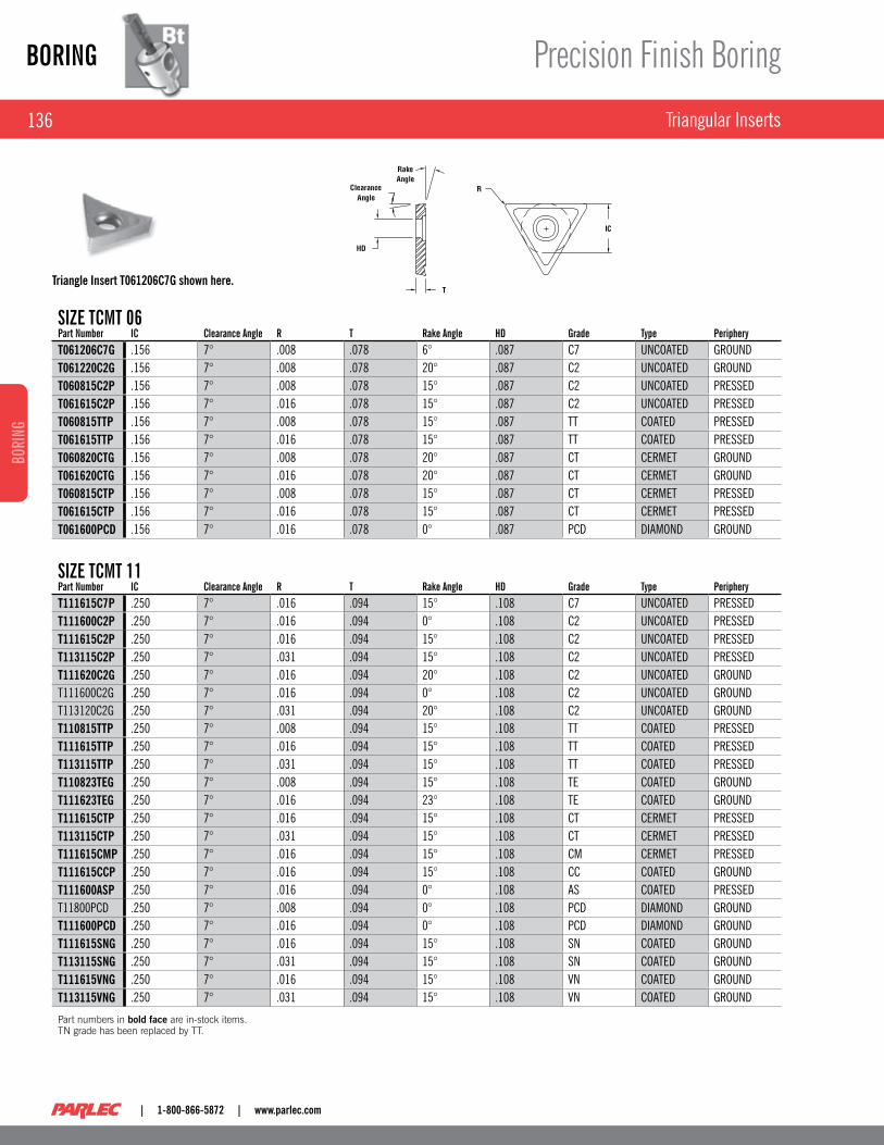
Triangular Inserts
Precision Finish Boring
sIZE TCMT 06part Number IC Clearance angle R T Rake angle hd Grade Type peripheryT061206C7G .156 7° .008 .078 6° .087 C7 UNCOATED gROUNDT061220C2G .156 7° .008 .078 20° .087 C2 UNCOATED gROUNDT060815C2P .156 7° .008 .078 15° .087 C2 UNCOATED PRESSEDT061615C2P .156 7° .016 .078 15° .087 C2 UNCOATED PRESSEDT060815TTP .156 7° .008 .078 15° .087 TT COATED PRESSEDT061615TTP .156 7° .016 .078 15° .087 TT COATED PRESSEDT060820CTG .156 7° .008 .078 20° .087 CT CERMET gROUNDT061620CTG .156 7° .016 .078 20° .087 CT CERMET gROUNDT060815CTP .156 7° .008 .078 15° .087 CT CERMET PRESSEDT061615CTP .156 7° .016 .078 15° .087 CT CERMET PRESSEDT061600PCD .156 7° .016 .078 0° .087 PCD DIAMOND gROUND
sIZE TCMT 11part Number IC Clearance angle R T Rake angle hd Grade Type peripheryT111615C7P .250 7° .016 .094 15° .108 C7 UNCOATED PRESSEDT111600C2P .250 7° .016 .094 0° .108 C2 UNCOATED PRESSEDT111615C2P .250 7° .016 .094 15° .108 C2 UNCOATED PRESSEDT113115C2P .250 7° .031 .094 15° .108 C2 UNCOATED PRESSEDT111620C2G .250 7° .016 .094 20° .108 C2 UNCOATED gROUNDT111600C2g .250 7° .016 .094 0° .108 C2 UNCOATED gROUNDT113120C2g .250 7° .031 .094 20° .108 C2 UNCOATED gROUNDT110815TTP .250 7° .008 .094 15° .108 TT COATED PRESSEDT111615TTP .250 7° .016 .094 15° .108 TT COATED PRESSEDT113115TTP .250 7° .031 .094 15° .108 TT COATED PRESSEDT110823TEG .250 7° .008 .094 15° .108 TE COATED gROUNDT111623TEG .250 7° .016 .094 23° .108 TE COATED gROUNDT111615CTP .250 7° .016 .094 15° .108 CT CERMET PRESSEDT113115CTP .250 7° .031 .094 15° .108 CT CERMET PRESSEDT111615CMP .250 7° .016 .094 15° .108 CM CERMET PRESSEDT111615CCP .250 7° .016 .094 15° .108 CC COATED gROUNDT111600ASP .250 7° .016 .094 0° .108 AS COATED PRESSEDT11800PCD .250 7° .008 .094 0° .108 PCD DIAMOND gROUNDT111600PCD .250 7° .016 .094 0° .108 PCD DIAMOND gROUNDT111615SNG .250 7° .016 .094 15° .108 SN COATED gROUNDT113115SNG .250 7° .031 .094 15° .108 SN COATED gROUNDT111615VNG .250 7° .016 .094 15° .108 VN COATED gROUNDT113115VNG .250 7° .031 .094 15° .108 VN COATED gROUND
Part numbers in bold face are in-stock items. TN grade has been replaced by TT.
Triangle Insert T061206C7G shown here.
137
BORINGBORING
www.parlec.com | 1-800-866-5872 |
Components
Precision Finish Boring
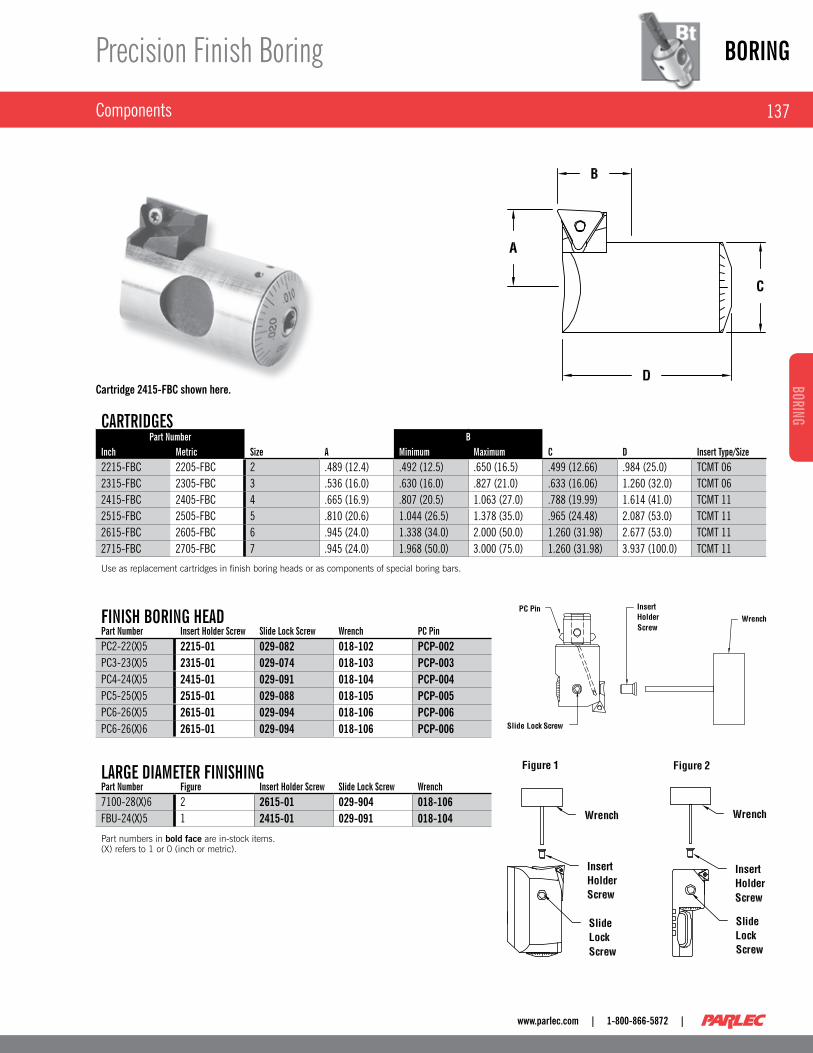
Cartridge 2415-FBC shown here.
CaRTRIdGEspart Number B
Inch Metric size a Minimum Maximum C d Insert Type/size2215-FBC 2205-FBC 2 .489 (12 .4) .492 (12 .5) .650 (16 .5) .499 (12 .66) .984 (25 .0) TCMT 062315-FBC 2305-FBC 3 .536 (16 .0) .630 (16 .0) .827 (21 .0) .633 (16 .06) 1 .260 (32 .0) TCMT 062415-FBC 2405-FBC 4 .665 (16 .9) .807 (20 .5) 1 .063 (27 .0) .788 (19 .99) 1 .614 (41 .0) TCMT 112515-FBC 2505-FBC 5 .810 (20 .6) 1 .044 (26 .5) 1 .378 (35 .0) .965 (24 .48) 2 .087 (53 .0) TCMT 112615-FBC 2605-FBC 6 .945 (24 .0) 1 .338 (34 .0) 2 .000 (50 .0) 1 .260 (31 .98) 2 .677 (53 .0) TCMT 112715-FBC 2705-FBC 7 .945 (24 .0) 1 .968 (50 .0) 3 .000 (75 .0) 1 .260 (31 .98) 3 .937 (100 .0) TCMT 11
Use as replacement cartridges in finish boring heads or as components of special boring bars.
FINIsh BORING hEadpart Number Insert holder screw slide lock screw Wrench pC pinPC2-22(X)5 2215-01 029-082 018-102 PCP-002PC3-23(X)5 2315-01 029-074 018-103 PCP-003PC4-24(X)5 2415-01 029-091 018-104 PCP-004PC5-25(X)5 2515-01 029-088 018-105 PCP-005PC6-26(X)5 2615-01 029-094 018-106 PCP-006PC6-26(X)6 2615-01 029-094 018-106 PCP-006
laRGE dIaMETER FINIshINGpart Number Figure Insert holder screw slide lock screw Wrench7100-28(X)6 2 2615-01 029-904 018-106FBU-24(X)5 1 2415-01 029-091 018-104
Part numbers in bold face are in-stock items. (X) refers to 1 or 0 (inch or metric).

BORING
138
BORI
NG
| 1-800-866-5872 | www.parlec.com
Twin Bore Roughing from .95” to 6 .00” (25mm to 152 .4mm)
Boring Heads
Independent height and diameter setting permits balanced cutting ■with production of almost perfectly round holes from the beginning, irrespective of core shifts .Two height balanceable cutting edges results in metal removal at rates ■almost 4 times that of a single cutter .Height adjustments are made with a cam that supports the insert ■holder where needed, at the furthest radial point .Each insert holder can be adjusted individually in diameter with a dial ■screw for fast, easy set-up operations .Balanced or stepped cutting can be done with the same set of insert ■holders permitting heavy stock removal and eliminating the need to purchase two sets of insert holders .Standard through-spindle coolant capability cools the insert and ■flushes chips .ISO standard inserts – requires no special expensive inserts . ■
Square SCMT insert holders with 6° lead for through hole boring or ■extreme core shifts .Diamond CCMT insert holders for boring to a square holder, or deep ■bore lengths . Trigon WCMT insert holders for applications requiring heavy stock ■removal .
PC4-4405 shown here.
TWIN BORE ROuGhINGpart Number Bore Range Min. Bore Range Max. Connection size Insert holder size Body diameter C Weight (lbs.)PC2-4205 .95 (24 .1) 1 .31 (33 .3) PC2 21 .91 (23) 1 .39 (33 .5) .2PC2-4205 1 .13 (28 .7)∗ 1 .48 (37 .6) PC2 22 .91 (23) 1 .39 (33 .5) .2PC3-4305 1 .27 (32 .3) 1 .70 (43 .2) PC3 31 1 .18 (30) 1 .57 (40) .4PC3-4305 1 .50 (38 .1)∗ 1 .95 (49 .5) PC3 32 1 .18 (30) 1 .57 (40) .4PC4-4405 1 .58 (40) 2 .17 (55 .1) PC4 41 1 .50 (38) 1 .85 (47) .7PC4-4405 2 .09 (53)∗ 2 .53 (64 .3) PC4 42 1 .50 (38) 1 .85 (47) .7PC5-4505 2 .06 (52 .4) 2 .73 (69 .3) PC5 51 1 .93 (49) 2 .24 (57) 1 .4PC5-4505 2 .58 (65 .5)∗ 3 .30 (83 .8) PC5 52 1 .93 (49) 2 .24 (57) 1 .4PC6-4605 2 .61 (66 .3) 3 .48 (88 .4) PC6 61 2 .48 (63) 2 .79 (71) 2 .8PC6-4605 3 .36 (85 .3) 4 .20 (106 .7) PC6 62 2 .48 (63) 2 .79 (71) 2 .8PC6-4605 4 .10 (104 .1)∗ 4 .86 (123 .4) PC6 63 2 .48 (63) 2 .79 (71) 2 .8PC6-4606 3 .92 (99 .6) 4 .84 (123) PC6 61 3 .54 (90) 2 .79 (71) 3 .9PC6-4606 4 .68 (119) 5 .54 (140 .7) PC6 62 3 .54 (90) 2 .79 (71) 3 .9PC6-4606 5 .44 (138) 6 .20 (157 .5) PC6 63 3 .54 (90) 2 .79 (71) 3 .9PC7-4705 3 .92 (99 .6) 4 .84 (122 .9) PC7 61 3 .54 (90) 4 .60 (117) –PC7-4705 4 .68 (119) 5 .54 (140 .7) PC7 62 3 .54 (90) 4 .60 (117) –PC7-4705 5 .44 (138) 6 .00 (152 .4) PC7 63 3 .54 (90) 4 .60 (117) –
Part numbers in bold face are in-stock items. For use when reduced boring shaft diameter is required for clearance. PC Connection OD should not be larger than the starting diameter of the hole.
139
BORINGBORING
www.parlec.com | 1-800-866-5872 |
Twin Bore Roughing from 6 .00” to 8 .27” (152 .4mm to 210mm)
Boring Heads
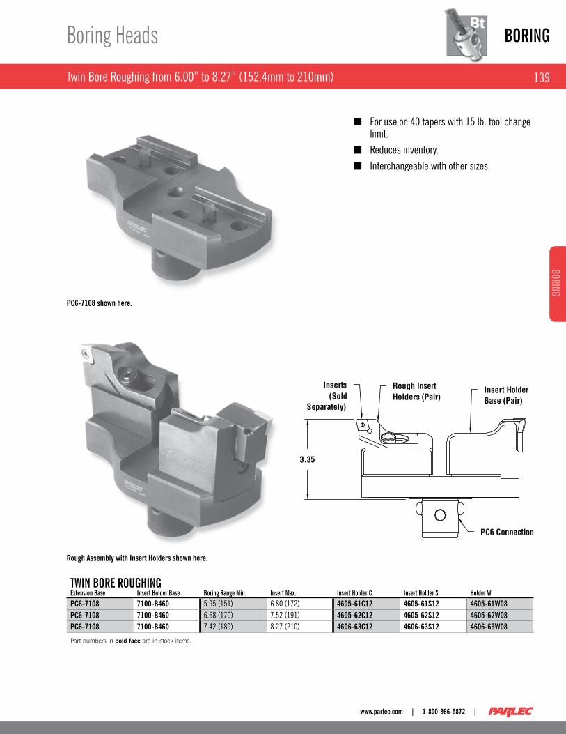
TWIN BORE ROuGhINGExtension Base Insert holder Base Boring Range Min. Insert Max. Insert holder C Insert holder s holder WPC6-7108 7100-B460 5 .95 (151) 6 .80 (172) 4605-61C12 4605-61S12 4605-61W08PC6-7108 7100-B460 6 .68 (170) 7 .52 (191) 4605-62C12 4605-62S12 4605-62W08PC6-7108 7100-B460 7 .42 (189) 8 .27 (210) 4606-63C12 4606-63S12 4606-63W08
Part numbers in bold face are in-stock items.
For use on 40 tapers with 15 lb . tool change ■limit .Reduces inventory . ■
Interchangeable with other sizes . ■
PC6-7108 shown here.
Rough Assembly with Insert Holders shown here.
BORING
140
BORI
NG
| 1-800-866-5872 | www.parlec.com
Twin Bore Roughing from 5 .94” to 21 .89” (151mm to 556mm)
Boring Heads
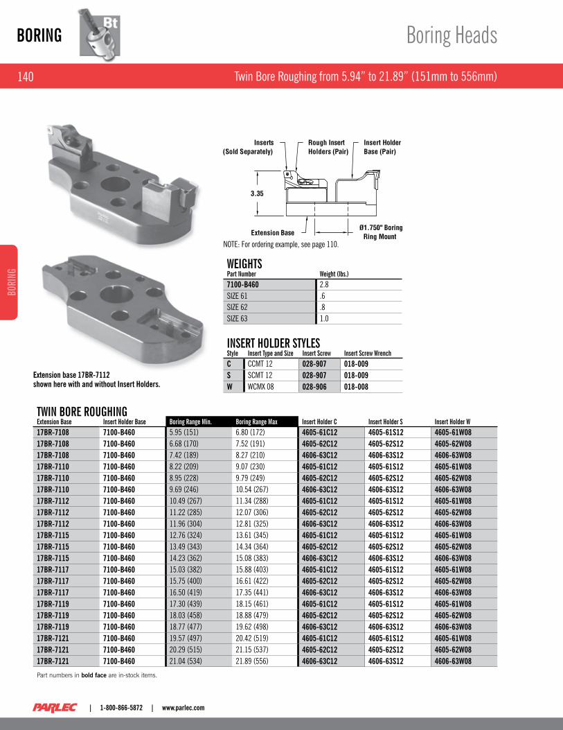
TWIN BORE ROuGhINGExtension Base Insert holder Base Boring Range Min. Boring Range Max Insert holder C Insert holder s Insert holder W17BR-7108 7100-B460 5 .95 (151) 6 .80 (172) 4605-61C12 4605-61S12 4605-61W0817BR-7108 7100-B460 6 .68 (170) 7 .52 (191) 4605-62C12 4605-62S12 4605-62W0817BR-7108 7100-B460 7 .42 (189) 8 .27 (210) 4606-63C12 4606-63S12 4606-63W0817BR-7110 7100-B460 8 .22 (209) 9 .07 (230) 4605-61C12 4605-61S12 4605-61W0817BR-7110 7100-B460 8 .95 (228) 9 .79 (249) 4605-62C12 4605-62S12 4605-62W0817BR-7110 7100-B460 9 .69 (246) 10 .54 (267) 4606-63C12 4606-63S12 4606-63W0817BR-7112 7100-B460 10 .49 (267) 11 .34 (288) 4605-61C12 4605-61S12 4605-61W0817BR-7112 7100-B460 11 .22 (285) 12 .07 (306) 4605-62C12 4605-62S12 4605-62W0817BR-7112 7100-B460 11 .96 (304) 12 .81 (325) 4606-63C12 4606-63S12 4606-63W0817BR-7115 7100-B460 12 .76 (324) 13 .61 (345) 4605-61C12 4605-61S12 4605-61W0817BR-7115 7100-B460 13 .49 (343) 14 .34 (364) 4605-62C12 4605-62S12 4605-62W0817BR-7115 7100-B460 14 .23 (362) 15 .08 (383) 4606-63C12 4606-63S12 4606-63W0817BR-7117 7100-B460 15 .03 (382) 15 .88 (403) 4605-61C12 4605-61S12 4605-61W0817BR-7117 7100-B460 15 .75 (400) 16 .61 (422) 4605-62C12 4605-62S12 4605-62W0817BR-7117 7100-B460 16 .50 (419) 17 .35 (441) 4606-63C12 4606-63S12 4606-63W0817BR-7119 7100-B460 17 .30 (439) 18 .15 (461) 4605-61C12 4605-61S12 4605-61W0817BR-7119 7100-B460 18 .03 (458) 18 .88 (479) 4605-62C12 4605-62S12 4605-62W0817BR-7119 7100-B460 18 .77 (477) 19 .62 (498) 4606-63C12 4606-63S12 4606-63W0817BR-7121 7100-B460 19 .57 (497) 20 .42 (519) 4605-61C12 4605-61S12 4605-61W0817BR-7121 7100-B460 20 .29 (515) 21 .15 (537) 4605-62C12 4605-62S12 4605-62W0817BR-7121 7100-B460 21 .04 (534) 21 .89 (556) 4606-63C12 4606-63S12 4606-63W08
Part numbers in bold face are in-stock items.
INsERT hOldER sTylEsstyle Insert Type and size Insert screw Insert screw WrenchC CCMT 12 028-907 018-009S SCMT 12 028-907 018-009W WCMX 08 028-906 018-008
WEIGhTspart Number Weight (lbs.)7100-B460 2 .8SIzE 61 .6SIzE 62 .8SIzE 63 1 .0
Extension base 17BR-7112 shown here with and without Insert Holders.
NOTE: For ordering example, see page 110 .
141
BORINGBORING
www.parlec.com | 1-800-866-5872 |
Insert Holders
Twin Bore Roughing
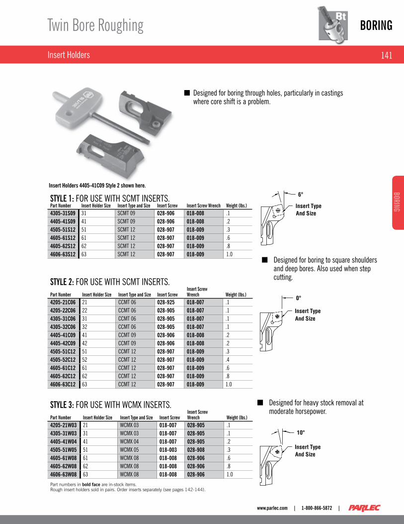
sTylE 1: FOR USE WITH SCMT INSERTS .part Number Insert holder size Insert Type and size Insert screw Insert screw Wrench Weight (lbs.)4305-31S09 31 SCMT 09 028-906 018-008 .14405-41S09 41 SCMT 09 028-906 018-008 .24505-51S12 51 SCMT 12 028-907 018-009 .34605-61S12 61 SCMT 12 028-907 018-009 .64605-62S12 62 SCMT 12 028-907 018-009 .84606-63S12 63 SCMT 12 028-907 018-009 1 .0
Designed for boring through holes, particularly in castings ■where core shift is a problem .
sTylE 2: FOR USE WITH SCMT INSERTS .part Number Insert holder size Insert Type and size Insert screw
Insert screw Wrench Weight (lbs.)
4205-21C06 21 CCMT 06 028-925 018-007 .14205-22C06 22 CCMT 06 028-905 018-007 .14305-31C06 31 CCMT 06 028-905 018-007 .14305-32C06 32 CCMT 06 028-905 018-007 .14405-41C09 41 CCMT 09 028-906 018-008 .24405-42C09 42 CCMT 09 028-906 018-008 .24505-51C12 51 CCMT 12 028-907 018-009 .34505-52C12 52 CCMT 12 028-907 018-009 .44605-61C12 61 CCMT 12 028-907 018-009 .64605-62C12 62 CCMT 12 028-907 018-009 .84606-63C12 63 CCMT 12 028-907 018-009 1 .0
Designed for boring to square shoulders ■and deep bores . Also used when step cutting .
sTylE 3: FOR USE WITH WCMX INSERTS .part Number Insert holder size Insert Type and size Insert screw
Insert screw Wrench Weight (lbs.)
4205-21W03 21 WCMX 03 018-007 028-905 .14305-31W03 31 WCMX 03 018-007 028-905 .14405-41W04 41 WCMX 04 018-007 028-905 .24505-51W05 51 WCMX 05 018-003 028-908 .34605-61W08 61 WCMX 08 018-008 028-906 .64605-62W08 62 WCMX 08 018-008 028-906 .84606-63W08 63 WCMX 08 018-008 028-906 1 .0
Part numbers in bold face are in-stock items. Rough insert holders sold in pairs. Order inserts separately (see pages 142-144).
Designed for heavy stock removal at ■moderate horsepower .
Insert Holders 4405-41C09 Style 2 shown here.
BORING
142
BORI
NG
| 1-800-866-5872 | www.parlec.com
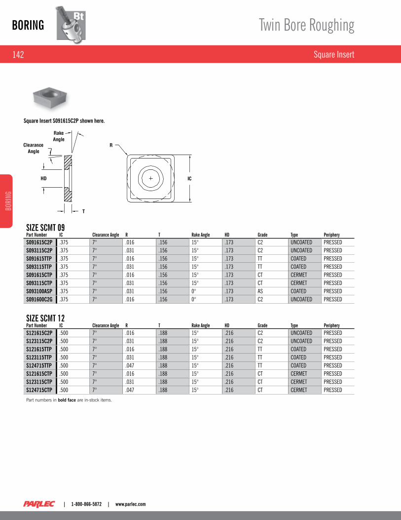
Square Insert
Twin Bore Roughing
Square Insert S091615C2P shown here.
sIZE sCMT 09part Number IC Clearance angle R T Rake angle hd Grade Type peripheryS091615C2P .375 7° .016 .156 15° .173 C2 UNCOATED PRESSEDS093115C2P .375 7° .031 .156 15° .173 C2 UNCOATED PRESSEDS091615TTP .375 7° .016 .156 15° .173 TT COATED PRESSEDS093115TTP .375 7° .031 .156 15° .173 TT COATED PRESSEDS091615CTP .375 7° .016 .156 15° .173 CT CERMET PRESSEDS093115CTP .375 7° .031 .156 15° .173 CT CERMET PRESSEDS093100ASP .375 7° .031 .156 0° .173 AS COATED PRESSEDS091600C2G .375 7° .016 .156 0° .173 C2 UNCOATED PRESSED
sIZE sCMT 12part Number IC Clearance angle R T Rake angle hd Grade Type peripheryS121615C2P .500 7° .016 .188 15° .216 C2 UNCOATED PRESSEDS123115C2P .500 7° .031 .188 15° .216 C2 UNCOATED PRESSEDS121615TTP .500 7° .016 .188 15° .216 TT COATED PRESSEDS123115TTP .500 7° .031 .188 15° .216 TT COATED PRESSEDS124715TTP .500 7° .047 .188 15° .216 TT COATED PRESSEDS121615CTP .500 7° .016 .188 15° .216 CT CERMET PRESSEDS123115CTP .500 7° .031 .188 15° .216 CT CERMET PRESSEDS124715CTP .500 7° .047 .188 15° .216 CT CERMET PRESSED
Part numbers in bold face are in-stock items.

143
BORINGBORING
www.parlec.com | 1-800-866-5872 |
Twin Bore Roughing
80° Diamond Inserts
80° Diamond Insert shown here.
sIZE CCMT 06part Number IC Clearance angle R T Rake angle hd Grade Type peripheryC061615C2P .250 7° .016 .094 15° .110 C2 UNCOATED PRESSEDC063115C2P .250 7° .031 .094 15° .110 C2 UNCOATED PRESSEDC061620C2G .250 7° .016 .094 20° .110 C2 UNCOATED gROUNDC061615TTP .250 7° .016 .094 15° .110 TT COATED PRESSEDC063115TTP .250 7° .031 .094 15° .110 TT COATED PRESSEDC061615CTP .250 7° .016 .094 15° .110 CT CERMET PRESSEDC063115CTP .250 7° .031 .094 15° .110 CT CERMET PRESSEDC063115SNG .250 7° .031 .094 15° .110 SN COATED gROUNDC061615SNG .250 7° .016 .094 15° .110 SN COATED gROUNDC061615VNG .250 7° .016 .094 15° .110 VN COATED gROUNDC063115VNG .250 7° .031 .094 15° .110 VN COATED gROUNDC093115VNG .375 7° .031 .156 15° .173 VN COATED gROUND
sIZE CCMT 09part Number IC Clearance angle R T Rake angle hd Grade Type peripheryC091615C2P .375 7° .016 .156 15° .173 C2 UNCOATED PRESSEDC093115C2P .375 7° .031 .156 15° .173 C2 UNCOATED PRESSEDC091620C2G .375 7° .016 .156 20° .173 C2 UNCOATED gROUNDC091615TTP .375 7° .016 .156 15° .173 TT COATED PRESSEDC093115TTP .375 7° .031 .156 15° .173 TT COATED PRESSEDC091615CTP .375 7° .016 .156 15° .173 CT CERMET PRESSEDC093115CTP .375 7° .031 .156 15° .173 CT CERMET PRESSEDC091615SNG .375 7° .016 .156 15° .173 SN COATED gROUNDC093115SNG .375 7° .031 .156 15° .173 SN COATED gROUNDC091615VNG .375 7° .016 .156 15° .173 VN COATED gROUND
sIZE CCMT 12part Number IC Clearance angle R T Rake angle hd Grade Type peripheryC121615C2P .500 7° .016 .188 15° .216 C2 UNCOATED PRESSEDC123115C2P .500 7° .031 .188 15° .216 C2 UNCOATED PRESSEDC124715C2P .500 7° .047 .188 15° .216 C2 UNCOATED PRESSEDC121620C2G .500 7° .016 .188 20° .216 C2 UNCOATED gROUNDC123120C2G .500 7° .031 .188 20° .216 C2 UNCOATED gROUNDC121615TTP .500 7° .016 .188 15° .216 TT COATED PRESSEDC123115TTP .500 7° .031 .188 15° .216 TT COATED PRESSEDC124715TTP .500 7° .047 .188 15° .216 TT COATED PRESSEDC121615CTP .500 7° .016 .188 15° .216 CT CERMET PRESSEDC123115CTP .500 7° .031 .188 15° .216 CT CERMET PRESSEDC124715CTP .500 7° .047 .188 15° .216 CT CERMET PRESSEDC121615SNG .500 7° .016 .188 15° .216 SN COATED gROUNDC123115SNG .500 7° .031 .188 15° .216 SN COATED gROUNDC121615VNG .500 7° .016 .188 15° .216 VN COATED gROUNDC123115VNG .500 7° .031 .188 15° .216 VN COATED gROUND

BORING
144
BORI
NG
| 1-800-866-5872 | www.parlec.com
Trigon Inserts
Twin Bore Roughing
sIZE WCMx 03part Number IC Clearance angle R T Rake angle hd Grade Type peripheryW033115TTP .218 7° .031 .093 15° .110 TT COATED PRESSED
sIZE WCMx 04part Number IC Clearance angle R T Rake angle hd Grade Type peripheryW043115TTP .250 7° .031 .093 15° .122 TT COATED PRESSED
sIZE WCMx 05part Number IC Clearance angle R T Rake angle hd Grade Type peripheryW053115TTP .312 7° .031 .125 15° .126 TT CERMET PRESSED
sIZE WCMx 08part Number IC Clearance angle R T Rake angle hd Grade Type peripheryW084715TTP .500 7° .047 .187 15° .169 TT COATED PRESSED
Part numbers in bold face are in-stock items.
Trigon Insert W033115STTP shown here.
145
BORINGBORING
www.parlec.com | 1-800-866-5872 |
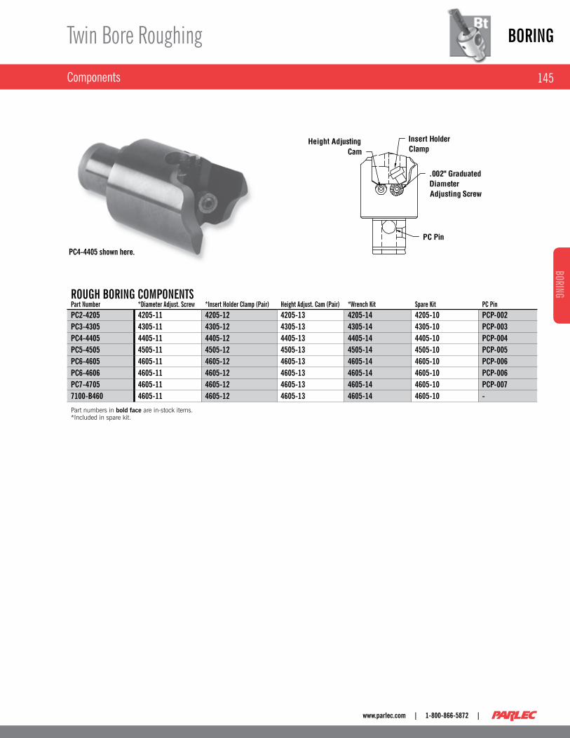
Components
Twin Bore Roughing
PC4-4405 shown here.
ROuGh BORING COMpONENTspart Number *diameter adjust. screw *Insert holder Clamp (pair) height adjust. Cam (pair) *Wrench Kit spare Kit pC pinPC2-4205 4205-11 4205-12 4205-13 4205-14 4205-10 PCP-002PC3-4305 4305-11 4305-12 4305-13 4305-14 4305-10 PCP-003PC4-4405 4405-11 4405-12 4405-13 4405-14 4405-10 PCP-004PC5-4505 4505-11 4505-12 4505-13 4505-14 4505-10 PCP-005PC6-4605 4605-11 4605-12 4605-13 4605-14 4605-10 PCP-006PC6-4606 4605-11 4605-12 4605-13 4605-14 4605-10 PCP-006PC7-4705 4605-11 4605-12 4605-13 4605-14 4605-10 PCP-0077100-B460 4605-11 4605-12 4605-13 4605-14 4605-10 -
Part numbers in bold face are in-stock items. *Included in spare kit.

BORING
146
BORI
NG
| 1-800-866-5872 | www.parlec.com
Collet Chucks & Morse Tapers
Modular Toolholding
MOdulaR COllET ChuCKpart Number Connection size Type/size projection page #PC4-16ER325 PC4 ER16 3 .12 TH 31PC4-18DC2 PC4 DA 180 2 .28 TH 51PC4-20ER325 PC4 ER 20 3 .25 TH 31PC4-32ER325 PC4 ER 32 3 .25 TH 33PC6-10SC3 PC6 100 Pg 3 .25 TH 42PC6-18DC2 PC6 DA 180 3 .43 TH 51PC6-20ER340 PC6 ER 20 3 .40 TH 31PC6-32ER340 PC6 ER 32 3 .40 TH 33
MOdulaR MORsE TapER hOldERspart Number Connection size size projection page #PC6-02MT4 PC6 #2 MT 3 .91 TH 84PC6-03MT5 PC6 #3 MT 4 .78 TH 84PC6-04MT6 PC6 #4 MT 5 .53 TH 84
Part numbers in bold face are in-stock items.

147
BORINGBORING
www.parlec.com | 1-800-866-5872 |
End Mill and Shell Mill Holders
Modular Toolholding
MOdulaR ENd MIll hOldERspart Number Connection size size projection page #PC4-50EM3 PC4 .500 3 .13 TH 72PC4-62EM3 PC4 .625 3 .13 TH 73PC4-75EM3 PC4 .750 3 .13 TH 73PC6-25EM1 PC6 .250 1 .28 TH 71PC6-37EM1 PC6 .375 1 .78 TH 79PC6-50EM2 PC6 .500 1 .90 TH 72PC6-62EM3 PC6 .625 3 .03 TH 73PC6-75EM3 PC6 .750 3 .03 TH 73PC6-87EM3 PC6 .875 3 .03 TH 74PC6-10EM3 PC6 1 .000 3 .28 TH 74PC6-12EM3 PC6 1 .250 3 .28 TH 75
MOdulaR shEll MIll hOldERspart Number Connection size size projection page #PC4-75SM1 PC4 .750 .78 TH 78PC6-75SM1 PC6 .750 .78 TH 78PC6-10SM1 PC6 1 .000 .78 TH 79PC6-12SM1 PC6 1 .250 1 .03 TH 79PC6-15SM2 PC6 1 .500 153 .00 TH 80
Part numbers in bold face are in-stock items. Tapping Heads Available on request (see page 170, 171)
BORING
148
BORI
NG
| 1-800-866-5872 | www.parlec.com
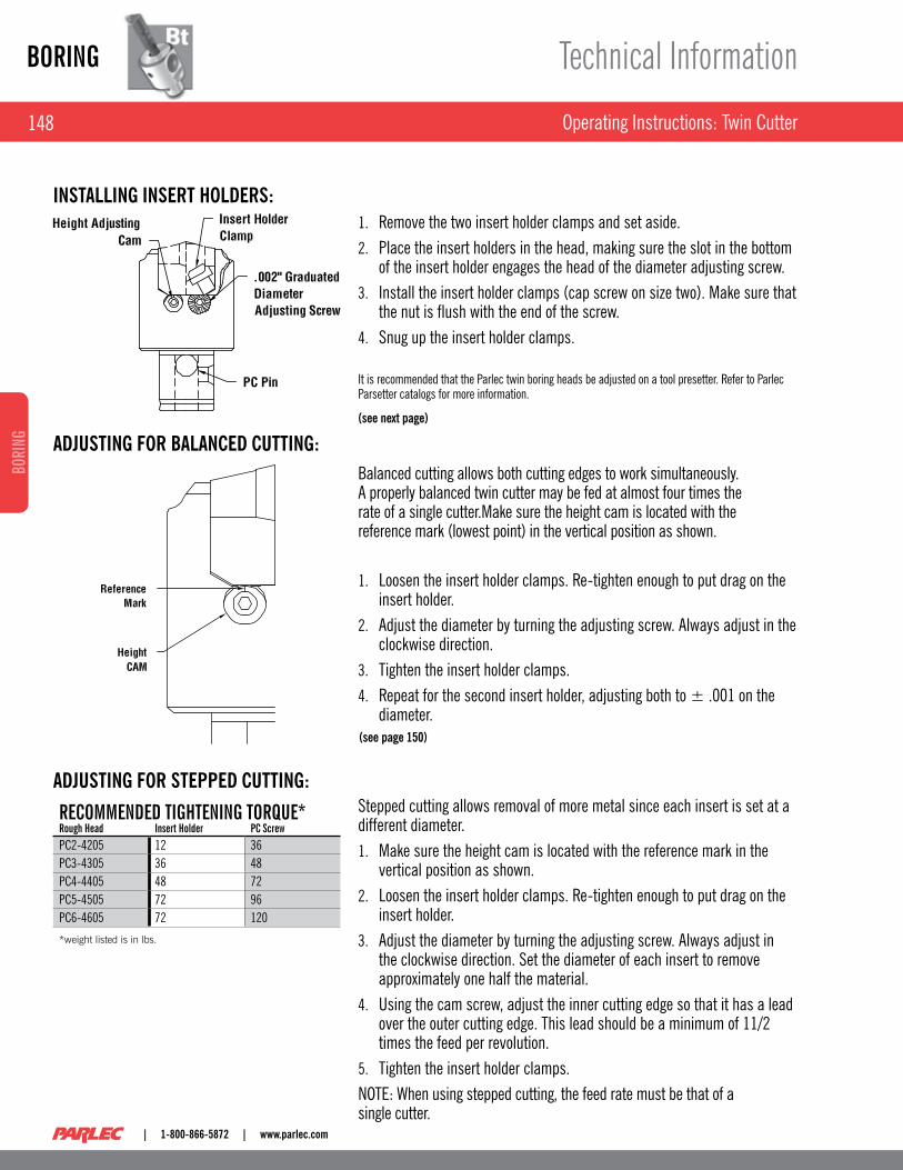
Operating Instructions: Twin Cutter
Technical Information
Remove the two insert holder clamps and set aside .1 .
Place the insert holders in the head, making sure the slot in the bottom 2 . of the insert holder engages the head of the diameter adjusting screw .Install the insert holder clamps (cap screw on size two) . Make sure that 3 . the nut is flush with the end of the screw .Snug up the insert holder clamps . 4 .
It is recommended that the Parlec twin boring heads be adjusted on a tool presetter . Refer to Parlec Parsetter catalogs for more information .
INSTALLING INSERT HOLDERS:
ADjUSTING FOR BALANCED CUTTING:
ADjUSTING FOR STEPPED CUTTING:
Balanced cutting allows both cutting edges to work simultaneously . A properly balanced twin cutter may be fed at almost four times the rate of a single cutter .Make sure the height cam is located with the reference mark (lowest point) in the vertical position as shown .
Loosen the insert holder clamps . Re-tighten enough to put drag on the 1 . insert holder .Adjust the diameter by turning the adjusting screw . Always adjust in the 2 . clockwise direction .Tighten the insert holder clamps .3 .
Repeat for the second insert holder, adjusting both to ± .001 on the 4 . diameter .
(see next page)
(see page 150)
Stepped cutting allows removal of more metal since each insert is set at a different diameter .
Make sure the height cam is located with the reference mark in the 1 . vertical position as shown .Loosen the insert holder clamps . Re-tighten enough to put drag on the 2 . insert holder .Adjust the diameter by turning the adjusting screw . Always adjust in 3 . the clockwise direction . Set the diameter of each insert to remove approximately one half the material .Using the cam screw, adjust the inner cutting edge so that it has a lead 4 . over the outer cutting edge . This lead should be a minimum of 11/2 times the feed per revolution .Tighten the insert holder clamps .5 .
NOTE: When using stepped cutting, the feed rate must be that of a single cutter .
RECOMMENdEd TIGhTENING TORQuE*Rough head Insert holder pC screwPC2-4205 12 36PC3-4305 36 48PC4-4405 48 72PC5-4505 72 96PC6-4605 72 120
*weight listed is in lbs.

149
BORINGBORING
www.parlec.com | 1-800-866-5872 |
Balanced Cutting
Technical Information
Balanced cutting occurs when both inserts are set to exactly the same height . This height balancing is much more important than diametric balancing . A slight difference in height, even that caused by the insert tolerance, can have a dramatic effect upon the tool's performance . This is particularly true in the case of long chipping materials .
EXAMPLE OF UNBALANCED CUT:Feed rate .016 IPR . ■
Insert "A" is .003 higher than insert "B ."(The tolerance on an M style ■insert is .002- .004 .)The material removed by insert "A" is .008" + .003" = .011" ■
The material removed by insert "B" is .008" - .003" = .005" ■
The chip taken by insert "A" is over twice as thick as that taken by ■insert "B" .
The difference in cutting forces caused by the differences in insert height illustrated above can have the following effects on the bar's performance:
Possible wobble or chatter; extra load on the machine tool;1 .
generally, the bore diameter becomes larger than the set diameter;2 .
Uniform chip formation is not possible, making it difficult to break and 3 . clear chips .
MaxIMuM sETTING dIFFERENCEBore diameter Range Insert height Cutting diameter .95 – 1 .31 .001 .0081 .26 – 1 .74 .001 .0121 .58 – 2 .17 .001 .0122 .06 – 2 .83 .002 .0162 .61 – 6 .00 .002 .0166 .00+ .002 .020
MAXIMUM ALLOWABLE SETTING DIFFERENCE BETWEEN INSERTS FOR BEST PERFORMANCE:

BORING
150
BORI
NG
| 1-800-866-5872 | www.parlec.com
Stepped Cutting
Technical Information
Stepped cutting is utilized when heavy depth of cut is required . The inserts are set at different diameters . The insert cutting the smaller diameter is given axial lead 1 .25 times greater than the feed per revolution over the other insert . Use only insert holders with 0° lead . Stepped cutting allows 1 .75 x the depth of cut per tables on page 144 . Feed rates must be reduced to .5 x appropriate value .
RULES OF STEPPED CUTTING:Use insert holders with 0° lead .1 . Set height in inner cutting edge to provide 2 . lead 1 .25 times greater than the feed per revolution .Feed rate as roughing with a single cutter .3 . Remove half of the material to be removed 4 . with each insert . This should be sufficient for most applications .
TO BALANCE CUTTING FORCES, USE THE FORMULA BELOW:
A 1 – Hole starting diameter
A 2 – Inside cutter set diameter
A 3 – Outside cutter set diameter
Lead = 1.25 X IPR

151
BORINGBORING
www.parlec.com | 1-800-866-5872 |
Roughing Speeds
Technical Information
RECOMMENDED ROUGHING SPEEDS
sTEElsMaterial BhN TT / sN vN CTCARBON STEEL C = 0.15% 125 300-450 600-800 650-1000CARBON STEEL C = 0.35% 150 300-500 600-800 625-950CARBON STEEL C = 0.70% 180-250 250-450 550-750 500-750ALLOy STEEL 4000 125-200 300-500 550-750 500-750ALLOy STEEL 5000 225 200-400 350-525 300-600ALLOy STEEL 8000 300 200-400 300-525 350-475STAINLESS STEEL, ANNEALED 400 SERIES 150-270 250-400 400-600 475-750STAINLESS STEEL, ANNEALED 300 SERIES 150-220 300-425 350-500 550-650CAST STEEL, LOW CARBON 150 200-325 450-650 400-550CAST STEEL, LOW ALLOy 150-250 200-300 250-400 300-425
All values are in SFM
OThER MaTERIalsMaterial BhN TT / sN al / vN as C2MALLEABLE CAST IRON, FERRITIC 110-150 525-700 600-1000 400-900 150-350MALLEABLE CAST IRON, PEARLITIC 150-270 250-400 400-800 300-800 100-250GREy CAST IRON, LOW TENSILE 150-220 525-800 400-900 300-1000 200-400GREy CAST IRON, HIGH TENSILE 200-330 350-600 400-700 300-600 150-300NODULAR IRON, FERRITIC 125-230 300-500 400-900 450-900 150-375NODULAR IRON, PEARLITIC 200-300 250-400 400-900 350-650 100-250ALUMINUM ALLOyS 30-120 – – – 600-1200ALUMINUM ALLOyS, CAST 100-130 – – – 600-1200
All values are in SFM.
330BHN = RC 35250BHN = RC 24-25220BHN = RC 20

BORING
152
BORI
NG
| 1-800-866-5872 | www.parlec.com
Rough Boring Feed Rates & Machining Allowance
Technical Information
allOWaNCE & FEEd RaTEsMachining allowance on diameter (Inches) dOC Feed Rates (IpR)*
Twin Boring head Material Optimum Min. Max. For Best Finish Min. Max.PC2-4205 ( .94 – 1 .34) Steels .10 .02 .14 .010 .008 .014
Cast Iron .16 .02 .24 .010 .006 .012Aluminum .12 .02 .24 .010 .006 .012
PC3-4305 (1 .26 – 1 .70) Steels .12 – .14 .04 .16 – .18 .014 .012 .018Cast Iron .20 .04 .28 .012 .008 .016Aluminum .20 .04 .28 .014 .012 .018
PC4-4405 (1 .58 – 2 .17) Steels .14 – .16 .04 .18 – .20 .014 .012 .020Cast Iron .24 .04 .31 .012 .012 .016Aluminum .24 .04 .31 .014 .008 .018
PC5-4505 (2 .06 – 3 .30) Steels .24 .06 .35 – .47 .018 .012 .024Cast Iron .39 .04 .55 .016 .012 .018Aluminum .39 .06 .55 .018 .008 .024
PC6-4605 (2 .61 – 6 .00) PC6-4606 & PC7-4705
Steels .28 – .39 .06 .35 – .47 .018 .012 .024Cast Iron .47 .04 .55 .016 .008 .018Aluminum .47 .04 .55 .018 .016 .024
ALL BIg BORE ABOVE 6 .00 Steels .28 – .39 .06 .35 – .47 .018 .012 .024Cast Iron .47 .04 .55 .016 .008 .018Aluminum .47 .04 .55 .018 .016 .024
Part numbers in bold face are in-stock items. *Feed rate is based on two cutting edges. When step cutting, multiply by .5.

153
BORINGBORING
www.parlec.com | 1-800-866-5872 |
Rough Boring Chip Formation
Technical Information
Chip formation when rough boring is very important . An ideal chip should be “C” shaped or look like a six or nine . The chips should also be short as illustrated below .
Proper chip formation is a function of the feed rate and the chip breaker on the insert . generally the feed rate should be 25% to 35% of the width of the chip breaker .
If the chip does not break, increase the feed rate provided that the following conditions exist:
The part and the fixture are sufficiently rigid; ■
The machine has sufficient horsepower; ■
The machining allowance does not exceed the stated maximum; ■
The tool is not overly long . ■
If the chip does not break with the increased feed rate, it may be necessary to change to an insert with a smaller chip breaker .
It is important to remember that the thin, wide chip produced from a low feed rate and a large machining allowance is difficult at best to break . As a general rule, the feed rate should be 10% to 30% of the machining allowance .

BORING
154
BORI
NG
| 1-800-866-5872 | www.parlec.com
Operating Instructions: Finish Boring
Technical Information
BORING BAR INSTALLATION
Loosen the clamp screws .1 .
Insert boring bar and reduction bushing (if applicable) into the carrier . 2 . Align reduction bushing with slots 90° to clamp screws .
Note: We do not recommend using boring bars with flats .
Adjust the boring bar to the minimum desired length .3 .
Rotate the boring bar to align the insert tip to the alignment mark atop 4 . the boring head body . The bar should be above the line for best timing .
Note: Adjusting the position of the insert tip adjusts the "timing" of the bar which optimizes the surface finish and performance .
Tighten the clamp screws .5 .
TORqUE SPECIFICATIONS: Slide Lock Screw: 10 ft . lbs .1 .
Boring Bar Clamp Screw: 20 ft . lbs .2 .
TORqUE SPECIFICATIONS: Slide Lock Screw: 10 ft . lbs .
BORING HEAD ADjUSTMENTInstall insert using the torque wrench provided .1 . Loosen lock screw .2 . Adjust tool position by turning and reading the dial . The dial is 3 . graduated in increments of .001" per graduation on the diameter . Fine adjustments of .0001" can be made utilizing the vernier scale . Always adjust by turning the spindle in the clockwise direction .Tighten the lock screw .4 .
Vernier Scale Side Slide Lock Screw Side
Clamp Screw Side Oil Side

155
BORINGBORING
www.parlec.com | 1-800-866-5872 |
Technical Information
Operating Instructions: Finish Boring
USING THE VERNIERFind the line on the dial that exactly lines up with a line on the Vernier scale . This is at the zero mark on the dial . This is the reference point . Diametral increases in tenths are achieved by turning the dial clockwise until the appropriate line on the dial lines up with the appropriate line on the Vernier scale . For a .0006" adjustment, move the 6 on the dial in line with the 6 on the scale .
TORqUE SPECIFICATIONS:
Slide Lock Screw: 10 ft . lbs .
Boring Bar Clamp Screw: 20 ft . lbs .
The vernier graduation is established by counting over the number of tenths adjustment desired beginning with the first graduation immediately to the right of the reference point on the vernier scale . If required, continue counting on the left side of the scale again moving counterclockwise as shown .
FINISH BORING HEAD MAINTENANCE: The Parlec precision boring head is constructed of alloy steel, stainless steel, and a graphite-based epoxy resin . The graphite resin is self-lubricating and requires no added maintenance . To insure long service life, two to four times a year depending on the severity of conditions, the head should be adjusted to the outward end of travel (do not force beyond mechanical stop) and a light spindle or machine oil applied to the exposed section of the carrier . This will lubricate the alloy components of the head . No further maintenance should be required .
Rotate the dial to align these marks for .0001" adjustment.

BORING
156
BORI
NG
| 1-800-866-5872 | www.parlec.com
Finish Boring Speeds
Technical Information
CuTTING spEEd EFFECTsvariable low speed high speedMACHINING TIME Longer ShorterSURFACE FINISH Coarser FinerPROBABILITy OF VIBRATION Lower Higher
RECOMMENdEd FINIshING spEEd FOR sTEElsteels BhN TR / TT / sN C1 / C2 al as TECARBON STEEL C = 0.15% 125 550-750 600-800 150-350 650-1000 950-1300CARBON STEEL C = 0.35% 150 525-800 600-800 150-350 625-950 850-1200CARBON STEEL C = 0.70% 180-250 425-625 550-750 150-250 500-750 750-950ALLOy STEEL 4000 125-200 425-625 550-750 150-250 500-750 750-950ALLOy STEEL 5000 225 250-500 350-525 150-250 300-600 400-650ALLOy STEEL 8000 300 200-400 300-525 100-200 350-475 400-500STAINLESS STEEL, ANNEALED 400 SERIES 150-270 400-625 400-600 150-250 475-750 425-650STAINLESS STEEL, ANNEALED 300 SERIES 150-220 450-550 350-500 150-300 550-650 425-650CAST STEEL, LOW CARBON 150 325-450 450-650 100-250 400-550 475-600CAST STEEL, LOW ALLOy 150-250 250-350 250-400 100-250 300-425 400-575CAST STEEL, HIGH ALLOy 160-250 – 250-400 75-250 – 400-500
All values are in SFM.
OThER MaTERIalsMaterial BhN TR / TT / sN C1 / C2 al as TEMALLEABLE CAST IRON, FERRITIC 110-150 525-700 300-450 600-1100 700-1000 –MALLEABLE CAST IRON, PEARLITIC 150-270 250-400 200-250 600-1000 300-750 –GREy CAST IRON, LOW TENSILE 150-220 525-800 325-525 400-1200 600-1600 –GREy CAST IRON, HIGH TENSILE 200-330 350-600 225-400 400-900 350-900 –NODULAR IRON, FERRITIC 125-230 300-500 300-400 400-950 450-900 –NODULAR IRON, PEARLITIC 200-300 250-400 200-350 400-700 350-700 –ALUMINUM ALLOyS 30-120 – 600-3000 – – –ALUMINUM ALLOyS, CAST 100-130 – 600-3000 – – –EXTRA HARD STEEL 50-65RC – 60-120 – – –WASPALLOy, DISCALLOy, INCOLOy 180-250 – 50-200 – – 150-350MONEL, INCONEL 125-250 – 45-90 – – 90-300TITANIUM 100-200 – 120-250 – – 325-500COPPER, BRASS, ZINC 50-150 – 500-1000 – – 50-1500
All values are in SFM Feed rates .002 - .008 IPR. For best finish, feed rate should be approximately 25% of insert nose radius. Refer to next page.
330 BHN = RC 35250 BHN = RC 24-25220 BHN = RC 20
The effects of cutting speed are illustrated in this chart:
EFFECTS OF CUTTING SPEED

157
BORINGBORING
www.parlec.com | 1-800-866-5872 |
FINIsh FEEd RaTE EFFECTsFeed Rates/depth of Cut Result Chip Form solutionsLow Chips Bird Nest:
Difficult to Remove1 . Increase Depth of Cut2 . Increase Feed Rate
Moderately Low Long Stringy Chips:Difficult to Remove
1 . Increase Depth of Cut2 . Increase Feed Rate
Ideal Chips Coil Like a Spring:Easy to Remove
Keep RunningMake Money!
Slightly Heavy Slight Deformationof Chip
If Finish is Bad,Decrease Speed
Heavy Deformation of ChipIncreased Cutting Forces
If Finish is Bad,Decrease Speed
Very Heavy Severe Deformation of ChipIncreased Cutting ForcesHeat Build Up
If Finish is Bad,Decrease Speedgood Chip for Roughing
Finish Boring Speeds
Technical Information
The best surface finish is produced when the tool is fed at approximately 25% of the tool nose radius . The effect on chip formation of the feed rate and depth of cut is illustrated below:
EFFECTS OF FINISH FEED RATES
DEPTH OF CUT
The depth of cut must be sufficient to allow the tool to cut and not rub . Too small a cut will cause the tool to be pushed away from the workpiece by the cutting pressure . The depth of cut must be large enough to let the insert bite as it cuts . Depth of cut is a function of material and insert nose radius . Generally, the ideal minimum diametral depth of cut is equal to the insert nose radius.
EFFECT OF NOSE RADIUS ON SURFACE FINISH
A larger nose radius produces a better surface finish . Care must be taken not to over feed the nose radius .
A .016 nose ■radius insert fed at .004 IPR produces a finish as shown at the right:
A .016 nose ■radius insert fed at .008 IPR produces a finish as shown at the right:
A .016 nose ■radius insert fed at .016 IPR produces a finish as shown at the right:
*For best finish, generally feed at 25% of nose radius .
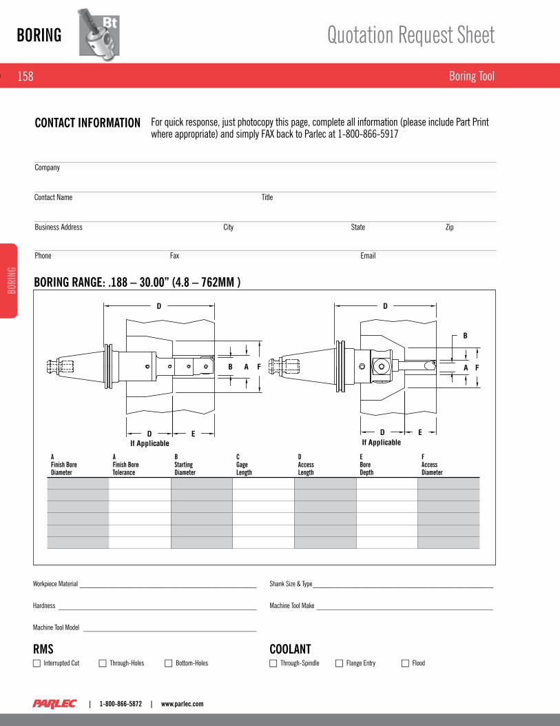
BORING
158
BORI
NG
| 1-800-866-5872 | www.parlec.com
Boring Tool
Quotation Request Sheet
For quick response, just photocopy this page, complete all information (please include Part Print where appropriate) and simply FAX back to Parlec at 1-800-866-5917
CONTACT INFORMATION
BORING RANGE: .188 – 30.00” (4.8 – 762MM )
Contact Name Title
Company
Business Address StateCity zip
Phone Fax Email
Workpiece Material _________________________________________________
Hardness _______________________________________________________
Machine Tool Model ________________________________________________
RMS c Interrupted Cut c Through-Holes c Bottom-Holes
Shank Size & Type __________________________________________________
Machine Tool Make _________________________________________________
COOLANT c Through-Spindle c Flange Entry c Flood
a Finish Borediameter
aFinish BoreTolerance
B starting diameter
CGagelength
daccesslength
EBoredepth
Faccessdiameter