![Catalogo 2015-16 ITA-ENG HQ - Allmatic - Sistemi di ... · Pignone in accaio ^ o ] v ] } v 13 64100001 64100005 64100006 Cod. 12006730 64108101 61400053 12000780 (64108100) 12007875](https://static.fdocuments.in/doc/165x107/5c67785509d3f2bf4a8bfbf6/catalogo-2015-16-ita-eng-hq-allmatic-sistemi-di-pignone-in-accaio-.jpg)
BOOMY - Allmatic
36
BOOMY BOOMY 4 BOOMY 4 BOOMY 4 LED BOOMY 4 LED BOOMY 6 BOOMY 6 BOOMY 6 LED BOOMY 6 LED Ambidextrous irreversible operator for driveways 6-1622396 - rev.4 - 21/12/2021 - firmware BOOMY01
Transcript of BOOMY - Allmatic

BOOMYBOOMY 4BOOMY 4BOOMY 4 LEDBOOMY 4 LEDBOOMY 6BOOMY 6BOOMY 6 LEDBOOMY 6 LED
Ambidextrous irreversible operator for driveways
6-1622396 - rev.4 - 21/12/2021 - firmware BOOMY01

2 / 36 - English 6-1622396 - rev. 4 - 21/12/2021
INDEX
1. GENERAL SAFETY WARNINGS 3
2. DESCRIPTION AND COMPATIBLE ACCESSORIES 4
3. PACKAGING LIST AND DIMENSIONS 5
4. PRELIMINARY VERIFICATIONS AND TECHNICAL CHARACTERISTICS 6
5. CABINET INSTALLATION AND ADJUSTMENTS 8
6. MANUAL HANDLING OF THE BOOM 16
7. ELECTRICAL CONNECTIONS AND INITIAL OPERATION 16
8. INSTALLATION OF ACCESSORIES TO THE CONTROL UNIT 18
9. CONTROL UNIT PROGRAMMING AND FUNCTIONALITY 20
10. RESOLVING PROBLEMS 34
11. DECLARATION OF CONFORMITY 34
12. MAINTENANCE 35
13. PRODUCT DISPOSAL 35
14. WARRANTY 35

English - 3 / 36 6-1622396 - rev. 4 - 21/12/2021
ATTENTION - FOR THE SAFETY OF PEOPLE IT IS IMPORTANT TO FOLLOW ALL THE INSTRUCTIONSKEEP THESE INSTRUCTIONS WITH CARE
1° - If it is not forecast in the electric gearcase, install a switch of magneto thermic type upstream, (omni polar with minimum opening of the contacts of 3 mm) with a check of conformity to the international standards. Such device must be protected against the accidental lockup (for example by installing inside a locked board).2° - For the section and the type of the cables ALLMATIC advices to use a cable of H05RN-F type with 1,5 sqmm minimum section and, however, to keep to the IEC 364 and installation standards in force in your country.3° - Positioning of a possible couple of photoelectric cells: the radius of the photoelectric cells must be at a height of no more than 70 cm from the ground and at a distance not superior to 20 cm from the motion plane of the door. Their correct working must be verified at the end of the installation in accordance with the point 7.2.1 of the EN 124454° - To fulfill the limits set by EN 12453, and in case the peak force exceeds the normative limit of 400 N it is necessary to have recourse to the active presence survey on the whole height of the door (up to max 2,5 m) - The photoelectric cells, in this case, must be applied in accordance with the point 7.3.2.2 of the EN 12445.N.B.: The earthing of the system is obligatory.The data described in this handbook are purely a guide.ALLMATIC reserves the right to change them in any moment.Carry out the system in the respect of the standards and laws in force.
IMPORTANT SAFETY INSTRUCTIONS FOR THE INSTALLATIONATTENTION - THE INCORRECT INSTALLATION CAN CAUSE SERIOUS DAMAGES
FOLLOW ALL INSTALLATION INSTRUCTIONS1° - This handbook is exclusively addressed to the specialized personnel who knows the constructive criteria and the protection devices against accidents for motorized gates, doors and main doors (follow the standards and the laws in force).2° - The installer will have to issue a handbook to the final user in accordance with the 12635.3° - Before proceeding with the installation, the installer must forecast the risks analysis of the final automatized closing and the safety of the identified dangerous points (Following the standards EN 12453/EN 12445).4° - Before installing the motion motor, the installer must verify that the gate is in good mechanical conditions and that it adequately opens and closes.5° - The installer must install the member for the manual release at a height inferior to 1,8 m.6° - The installer will have to remove possible impediments to the motorized motion of the gate (eg. door bolts, sliding bolts, door locks etc.)7° - The installer will permanently have to put the tags warning against the deflection on a very visible point or near possible fixed controls.8° - The wiring harness of the different electric components external to the operator (for example photoelectric cells, flashlights etc.) must be carried out according to the EN 60204-1 and the modifications to it done in the point 5.2.2 of the EN 12453.9° - The possible assembly of a keyboard for the manual control of the movement must be done by positioning the keyboard so that the person operating it does not find himself in a dangerous position; moreover, the risk of accidental activation of the buttons must be reduced.10° - Keep the automatism controls (push-button panel, remote control etc.) out of the children way. Command device for operating the motor (a switch manually closed) should be placed in area visible from the guided site and far from moving parts. It should be placed at least at 1,5 m height.11° - this appliance can be used by children aged from 8 years and above and persons with reduced physical, sensory or mental capabilities or lack of experience and knowledge if they have been given supervision or instruction concerning use of the appliance in a safe way and understand the hazards involved12° - children shall not play with the appliance13° - cleaning and user maintenance shall not be made by children without supervision14° - do not allow children to play with fixed controls. Keep remote controls away from children15° - Fixed command devices should be installed in a well visible way.16° - Before carrying out any installation, regulation or maintenance operation of the system, take off the voltage by operating on the special magneto thermic switch connected upstream.17° - At the end of the installation, the installer will have to make sure that the parts of thedoor do not encumber streets or public sidewalks.
THE ALLMATIC COMPANY DOES NOT ACCEPT ANY RESPONSIBILITY for possible damages caused by the non observan-ce during the installation of the safety standards and of the laws in force at present.
1. GENERAL SAFETY WARNINGS

4 / 36 - English 6-1622396 - rev. 4 - 21/12/2021
Operator raises irreversible road barrier ambidextrous electromechanical automated for opening and closing of the accesses of a driveway through rod. BOOMY has a 24V motor inside, with mechanical limit stop and encoder, which allows an accurate movement of the shaft indicated with LED indicators on the body and rod (both optional accessories). The control unit BIOS1 24 BOOMY can manage 3 digital inputs for photocells, 3 digital inputs for coils, wired inputs for commands STOP - OPEN - CLOSE - SS and two 24Vdc outputs for accessories and flashing lights. In addition, a 433mhz radio receiver with ALLMATIC encoding is already installed on board, allowing remote control of the automation. In case of power failure, BOOMY can continue to work in total safety thanks to the possibility to install inside a buffer battery kit connected directly to the control unit (optional accessory).
WARNING! The BOOMY barrier is only compatible with other ALLMATIC products.
BOOMY BASE PLATEBOOMY BASE PLATEPLATE for ground fixing complete with accessoriesPLATE for ground fixing complete with accessories 12007338
BOOM 4 METERSBOOM 4 METERSNo. 2 pieces of aluminum length 2.15 meters and ø 65 mmNo. 2 pieces of aluminum length 2.15 meters and ø 65 mmCoupling for connectionCoupling for connectionNo. 2 black caps of coverNo. 2 black caps of cover
12007692
BOOM 6 METERSBOOM 6 METERSNo. 2 pieces of aluminum length 3.15 meters and ø 80 mmNo. 2 pieces of aluminum length 3.15 meters and ø 80 mmCoupling for connectionCoupling for connectionNo. 2 black caps of coverNo. 2 black caps of cover
12007693
BUMPER KIT for BOOMYBUMPER KIT for BOOMYRubber bumper with accessoriesRubber bumper with accessories 12007304
LIGHTS KIT for BOOMY 4 METERLIGHTS KIT for BOOMY 4 METERNo. 2 led strips (length 4 meters)No. 2 led strips (length 4 meters)OpalinesOpalines
12007303
BATTERY KIT IN BOX for 4 METERSBATTERY KIT IN BOX for 4 METERSBox containing two 12V wired batteries, 7.2Ah rechargeableBox containing two 12V wired batteries, 7.2Ah rechargeableBracket for hanging box version 4mtBracket for hanging box version 4mtCable for connections 1,5mtCable for connections 1,5mt
12007306
BATTERY KIT IN BOX for 6 METERSBATTERY KIT IN BOX for 6 METERSBox containing two 12V wired batteries, 7.2Ah rechargeableBox containing two 12V wired batteries, 7.2Ah rechargeableBracket for hanging box version 6mtBracket for hanging box version 6mtCable for connections 1,5mtCable for connections 1,5mt
12007307
2. DESCRIPTION AND COMPATIBLE ACCESSORIES

English - 5 / 36 6-1622396 - rev. 4 - 21/12/2021
• • BOOMYBOOMY CABINET including gear motor with rocker and spring already installed for 4-6 meter long CABINET including gear motor with rocker and spring already installed for 4-6 meter long boom, boom, fixing “U” shape profile, screws, set of three keys and control unit BIOS1 24 BOOMY., screws, set of three keys and control unit BIOS1 24 BOOMY.
• • BOOMY LEDBOOMY LED CABINET including gear motor with rocker and springs already installed for 4-6 meter long CABINET including gear motor with rocker and springs already installed for 4-6 meter long boom, boom, fixing “U” shape profile, screws, set of three keys, control unit BIOS1 24 BOOMY, LED , screws, set of three keys, control unit BIOS1 24 BOOMY, LED interface board and LED strip on cabinet body already wired.interface board and LED strip on cabinet body already wired.
314
112
9
830
65
314
412
315
315
194
234
51
61
Boom side
4000 / 6000
80
60
FRONT VIEW
TOP VIEW
BASE PLATE
3. PACKAGING LIST AND DIMENSIONS
BATTERY CHARGER KIT for BOOMY24V battery charger board interface with plug-in connector 12007302
LED INTERFACE BOARDPlug-in board for BOOMY barrier led strip control 12007305

6 / 36 - English 6-1622396 - rev. 4 - 21/12/2021
The installation must be carried out only by qualified personnel, in compliance with laws, rules and regulations and as stated in these instructions.Before proceeding with the installation make sure that all the material to be used is in excellent condition and suitable for the intended use.Verify that the chosen environment for the installation is compatible with the total size of the product.Verify that the space around the automation allows an easy and safe execution of manual maneuvers.Check that there are no obstacles along the trajectory of the rod movement that could prevent opening and closing manoeuvres.Connect the power plant to a power supply line equipped with safety grounding.WARNING! It is mandatory to conform the plant to the rules and laws in force.
Description:1 - BOOMY2 - Photocells3 - Magnetic Loops4 - Photocell to detect presence near the automation (PH3)5 - Magnetic Loop to detect presence near the automation (S3)6 - Key selector
Parts to install meeting the EN 12453 standard
COMMAND TYPE
USE OF THE CLOSING
Skilled persons(out of a public
area*)
Skilled persons(public area)
Unrestricted use
with manned operation A B not possible
with visible impulses (e.g. sensor) C C C and D
with not visible impulses (e.g. transmitter) C C and D C and D
automatic C and D C and D C and D
* a typical example are those shutters which do not have access to any public way.A: Command button with manned operation (that is, operating as long as activated).B: Key selector with manned operation.C: Safety edges and/or other safety devices to keep thrust force within the limits of EN12453 regulation - Appendix A.D: Photocells.
4
2
1
3
5
6EXAMPLE OF INSTALLATION LAYOUT
4. PRELIMINARY VERIFICATIONS AND TECHNICAL CHARACTERISTICS

English - 7 / 36 6-1622396 - rev. 4 - 21/12/2021
Description:A. Control Unit Box BIOS1 24 BOOMYB. Mechanical stopsC. Rocker armD. Tie-rodE. Balance springF. Spring anchor points to cabinetG. Gear motorH. Unlocking plug with key lockI. BoomJ. HubK. Fixing “U” shape profile
TECHNICAL CHARACTERISTICS U.M.BOOMY 4
BOOMY 4 LEDBOOMY 6
BOOMY 6 LED
Power supply Vac 230 120 230 120
Frequency Hz 60 50 60 50
Control Unit BIOS1 24 BOOMY
BIOS1 24 BOOMY
BIOS1 24 BOOMY
BIOS1 24 BOOMY
Motor power supply Vdc 24 24 24 24
Motor power consumption A 6 6 6 6
Motor power W 140 140 140 140
Opening time at 90° sec. 3 3 3,5 3,5
Lenght of the pole m 4 4 6 6
Service % 100 100 100 100
Daily cicles recommended n° 1500 1500 1500 1500
Protection Degree IP 44 44 44 44
Overall cabinet body weight, without accessories kg 54 54 54 54
A
B
D
E
F
G
H
JI
K
C
4.1 BOOMY FRONT VIEW
8 / 36 - English 6-1622396 - rev. 4 - 21/12/2021
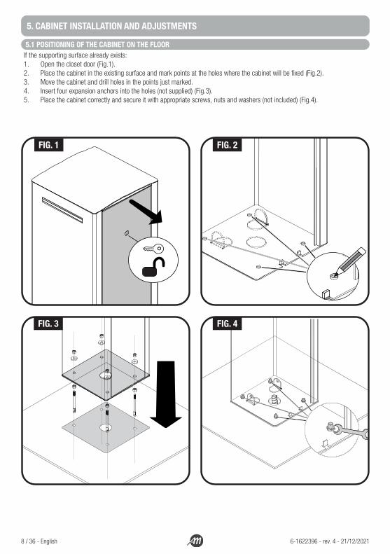
5. CABINET INSTALLATION AND ADJUSTMENTS
5.1 POSITIONING OF THE CABINET ON THE FLOORIf the supporting surface already exists:1. Open the closet door (Fig.1).2. Place the cabinet in the existing surface and mark points at the holes where the cabinet will be fixed (Fig.2).3. Move the cabinet and drill holes in the points just marked.4. Insert four expansion anchors into the holes (not supplied) (Fig.3).5. Place the cabinet correctly and secure it with appropriate screws, nuts and washers (not included) (Fig.4).
FIG. 1 FIG. 2
FIG. 3 FIG. 4

English - 9 / 36 6-1622396 - rev. 4 - 21/12/2021
If the supporting surface not already exists:1. Perform the foundation excavation to accommodate the foundation plate.2. Prepare the ducts for the passage of electrical cables.3. On the foundation plate, fix the four fangs by placing a nut and a washer on the upper and lower sides of the plate (Fig.5).4. Make the casting of concrete and, before starting the grip, place the foundation plate flush of the surface, parallel to the boom
and perfectly leveled (Fig.6).5. Wait until the concrete is completely taken; usually, at least two weeks.6. Remove the four upper nuts and washers from the fangs.7. Open the cabinet and place it correctly at the brackets and pipes for the passage of electric cables (Fig.8).8. Lock the cabinet with the appropriate nuts and washers just removed.
WARNING!The fixing surface must be perfectly flat, smooth and of such dimensions that it can withstand the weight of the entire structure to be installed.
2 wk
FIG. 5 FIG. 6
FIG. 7 FIG. 8

10 / 36 - English 6-1622396 - rev. 4 - 21/12/2021
5.2 INSTALLATION OF THE BOOM WITH MOVEMENT MANOEUVRE ORIENTED TO THE LEFTBOOMY is an ambidextrous operator and as a factory setting is assembled with the balance spring to the left and the opening/closing lever to the right. This setting is arbitrary and if you want to install the operator so that the boom maneuver is oriented to the left proceed by carrying out the following operations.
FOR THE 4 METERS VERSION:1. Loosen the tie-rod and unscrew the screw that locks it to the rocker arm (Fig.9).2. Remove the tie-rod and the spring (Fig.10).3. Attach one end of the spring to the bottom right anchor point inside the cabinet, and the other end to the tie-rod (Fig.11).4. Fix the tie-rod with the screw in the middle hole, to the right part of the rocket arm (Fig.12).
FOR THE 6 METERS VERSION:Unscrew the screws that lock the tie-rods to the rocker arm and fix them on the opposite side using the outer holes.
FIG. 9 FIG. 10
FIG. 11 FIG. 12

English - 11 / 36 6-1622396 - rev. 4 - 21/12/2021
5.3 INSTALLATION WITH LED KIT (OPTIONAL) - ONLY FOR 4 METERS VERSION
1. Take out the box of the control unit and remove the lid by unscrewing the screws (Fig.13).2. Install the LED interface card in the appropriate slot (in the BOOMY 4 LED version the card is already installed) (Fig.14).3. Drill two Ø 6 mm holes on the black plastic cap that covers the bottom of the boom (Fig.15).4. Pass the LED power cables through the holes just made, through the cable hole of the cabinet and through the cable hole of
the control box.5. Connect the led strips to the led card (Fig.16).
WARNING!Make sure the board is not powered before making connections.
G R +24 G R +24
Description:G LED channel GREENR LED channel RED+24 LED power supply +24Vdc PF1 Fuse T 1AJ1 PLUG-IN connector
1
LED RADIO
FUSE 1
FUSE 2
J2J1
J3
2 3 4 5 6 7 8 9 10 11 12 13 14 15 16 17
20 21
LED STATUS LED STATUS
J4
SLOT FOR THE LED INTERFACE BOARD
2 x Ø 6mm
FIG. 13 FIG. 14
FIG. 15 FIG. 16
12 / 36 - English 6-1622396 - rev. 4 - 21/12/2021
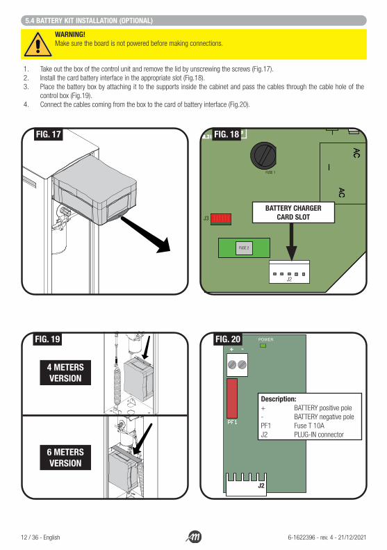
5.4 BATTERY KIT INSTALLATION (OPTIONAL)
1. Take out the box of the control unit and remove the lid by unscrewing the screws (Fig.17). 2. Install the card battery interface in the appropriate slot (Fig.18).3. Place the battery box by attaching it to the supports inside the cabinet and pass the cables through the cable hole of the
control box (Fig.19).4. Connect the cables coming from the box to the card of battery interface (Fig.20).
WARNING!Make sure the board is not powered before making connections.
+ -
J2
Description:+ BATTERY positive pole- BATTERY negative pole PF1 Fuse T 10AJ2 PLUG-IN connector
1
LED RADIO
FUSE 1
FUSE 2
J2J1
J3
2 3 4 5 6 7 8 9 10 11 12 13 14 15 16 17
20 21
LED STATUS LED STATUS
J4
BATTERY CHARGER CARD SLOT
FIG. 17 FIG. 18
FIG. 19 FIG. 20
4 METERSVERSION
6 METERSVERSION

English - 13 / 36 6-1622396 - rev. 4 - 21/12/2021
5.5 ASSEMBLY AND INSTALLATION OF THE BOOM1. Take a 2 (or 3) meter boom and put the “U” shape profile on it at one end.2. Emboss the “U” shape profile with the hub using the screws supplied, so that the boom is in vertical position and with the
protective rubber seats facing the direction of the movement of the boom (Fig.21).3. Put the cover (with the LED strip cables through if you use the LIGHTS KIT) on the bottom end of the boom.4. Unlock the motor with the hexagonal key provided and bring the boom manually in horizontal position (Fig.22). WARNING!
This operation brings the spring in tension and could be very dangerous.5. When the boom is in horizontal position, lock the motor with the key and then release the boom gently. Depending on the
internal position of the motor, the boom may rise slightly when released.6. Insert half of the coupling in the boom, if necessary help yourself with a plastic-head hammer (Fig.23-A).7. Drill two Ø 5mm holes in the boom with the drill at the groove on the joint, at least 50 mm apart from each other starting from
the boom head (Fig.23-B). 8. Make a Ø 10 mm socket on the holes just made and fix with two screws supplied the coupling to the boom.9. Insert in the coupling the second pole of 2 (or 3) meters, if necessary help yourself with a plastic-head hammer.10. Drill two Ø 5 mm holes in the second section of the boom with the drill at the groove on the joint, at least 50 mm apart from
each other starting from the beginning of the boom (Fig.23-C).11. Make a ø 10 mm socket on the holes just made and fix with two screws supplied the coupling to the boom.
A
B
C
2 x Ø 5mm
2 x Ø 5mm
60 50 60 50
FIG. 21 FIG. 22
FIG. 23 FIG. 24

14 / 36 - English 6-1622396 - rev. 4 - 21/12/2021
5.6 FINISHING AND MECHANICAL ADJUSTMENTS1. In case you install the KIT LIGHTS, slide the LED strips in the appropriate groove on the boom and, hand by hand, close them
with the opalines supplied.2. Fasten the “U” shape profile with screws firmly to the hub (Fig.25).3. Put the bottom rubber bumper by inserting it and sliding it through the guides for the entire length of the boom (if necessary
help yourself with silicone oil) (Fig.26).4. Insert the black cap into the end of the boom.5. Making sure that there are no people and objects within the range of the barrier, lightly press down the boom and unlock the
motor with the appropriate key.6. Gently accompany the natural movement of the boom.7. Act on the spring tie-rod until the boom remains in equilibrium alone with an inclination from the ground of about 45° (Fig.27).8. If you can not adjust the boom as the same tends to stay very close to the horizontal position proceed as follows:
• unlock the motor;• bring the boom in vertical position;• lock the motor;• move the tie-rod so that it is installed in the outermost hole of the balance-bar (see procedure ch. 5.2);• Resume procedure from point 7 of this chapter.
9. If you can not adjust the boom as the same tends to stay very close to the vertical position proceed as follows: • unlock the motor;• bring the boom in vertical position;• lock the motor;• move the tie-rod so that it is installed in the innermost hole of the balance-bar (see procedure ch. 5.2);• Resume procedure from point 7 of this chapter.
10. Adjust the mechanical stops and verify the desired position of the boom bringing the bar balance in both directions, then tighten the counternuts while holding the screws. Due the tight spaces, it is recommended to use ratchet wrenches for the operation (Fig.28).
11. Gently leave the boom so that it brings in 45° position.12. Lock the motor.
FIG. 25 FIG. 26

English - 15 / 36 6-1622396 - rev. 4 - 21/12/2021
45°
45°+-
+-
+
-
-+
1 2 3123
FIG. 27
FIG. 28

16 / 36 - English 6-1622396 - rev. 4 - 21/12/2021
WARNING! Carry out these operations only after removing the power supply to the motor.
In case of power failure, manual adjustments during the installation phase, or in case of emergency you can unlock the gearmotor so you can manually move the boom.
• Insert the key into the lock and remove the unlock cap.• Making sure that there are no people and objects within the range of the barrier, lightly press down
the boom.• Insert the supplied ALLMATIC hexagon wrench and rotate it half a turn to unlock the motor.
WARNING! This operation unlocks the motor brake from the boom.• Gently accompany the natural movement of the boom.
ATTENTION! In case of special situations where it was necessary to manually move the boom, once the system is restored it is recommended to perform the learning procedure again (see Chapter 7.1).
6. MANUAL HANDLING OF THE BOOM
7. ELECTRICAL CONNECTIONS AND INITIAL OPERATION
Open the cabinet and pull out the box containing the control unit.Pass the power cables through the cable gland inside the control box and connect them to the power transformer terminal board. Then switch ON power supply the control unit.
N
PEL FUSE
TRANSFORMER230V / 23V 50Hz
WARNING!Connect automation to a power supply line equipped with safety grounding (PE).
WARNING!The connection of the power supply must be performed by experienced and qualified personnel who meet the requirements and in full compliance with laws, rules and regulations.

English - 17 / 36 6-1622396 - rev. 4 - 21/12/2021
7.1 LEARNING PROCEDURE
Ensure that throughout the learning process, boom handling takes place in complete safety and that there are no interventions of safety devices that block the learning. In the latter case turn off the automation, manually bring the boom back to 45° respect the ground and start a new learning procedure.
1.Check that the boom is inclined to 45° relative to the ground, otherwise refer to the procedure of FINISHING AND MECHANICAL ADJUSTMENTS (Chapter 5.6).
2.Press at the same time the “UP“ and “MENU” buttons for at least 5 seconds until the display shows LOP.
3.If the automation DOESN’T MOVE in opening, press the “DOWN” button to stop the learning. The display shows L--.
4.Press the “SS” button to restart the procedure: the automation moves inopening, at reduced speed, until it reaches the limit switch. In this phase the display shows LOP.
5.Reached the opening limit switch, the automation moves automatically in closing, at running speed, until it reaches the closing limit switch. In this phase the display shows LCL.
6.Reached the closing limit switch, the automation moves automatically inclosing, at running speed, until it reaches the opening limit switch. In this phase the display shows LOP.
7Reached the opening limit switch, the automation moves in closing at running speed and with the slowdowns set into the menu LSI.
UP DOWN
MENU
SS
UP DOWN
MENU
SS
UP DOWN
MENU
SS

18 / 36 - English 6-1622396 - rev. 4 - 21/12/2021
Description:A. Terminal block accessories input and outputB. Radio ModuleC. Antenna terminal block D. J1 - Connector for plug-in led control boardE. J2 - Connector for battery charger cardF. J3 - Connector for external radio memoryG. Inputs and Securities Dip SwitchH. Display and buttonsI. Fuse1 - 10A fuse for motor protectionJ. Fuse2 - 2,5A fuse for accessories protectionK. Fuse - 2,5A fuse
WARNING!Please note that PH3 and S3 inputs are exclusively dedicated to the “presence sensor” (the photocell and the magnetic loop that is close to the automation) and cannot be used for other types of intervention. Like the STOP input, PH3 and S3 are both NORMALLY CLOSED inputs, so the control unit interrupts its normal operation if at least one of these contacts is open.
1
LED RADIO
FUSE 1
FUSE 2
J2J1
J3
2 3 4 5 6 7 8 9 10 11 12 13 14 15 16 17
20 21
LED STATUS LED STATUS
J4
N
PEL
230V 50Hz
FUSE
TRANSFORMER230V / 23V 50Hz
TX RX
GND
+ 24VTX
+24V
FLASHING LAMP24Vac 25W
24V M
STOP DRY CONTACT N.C.
LOOPS3
NC contact
A
G
H
EC D
F
K
J
I
A
B
8. INSTALLATION OF ACCESSORIES TO THE CONTROL UNIT
LoopDetector

English - 19 / 36 6-1622396 - rev. 4 - 21/12/2021
1: ground2: +24Vdc TX power supply (test photo)17: +24Vdc RX power supply6: common3 – 4 – 5: inputs NC or NO contact from photocells PH1, PH2, PH3The polarity of the inputs can be selected in the advanced menu, via PH1, PH2, PS3. ATTENTION! If not used, the photocell inputs should be disabled by setting in ON position DIP2 for PH1, DIP3 for PH2 and DIP4 for PH3 respectively.
8.1 PHOTOCELL CONNECTIONS
8.2 MAGNETIC LOOP CONNECTIONSIn order to connect a magnetic loop to the control unit, it is necessary to install a loop detector. Please refer to the detector instruction manual for setting up the loop.1: ground17: +24Vdc loop detector power supply10: common (loop detector output)7 – 8 – 9: inputs NC or NO contact from loops S1, S2, S3 (loop detector output)Connect the magnetic loop cables to the terminal block of the loop detector.The polarity of the inputs can be selected in the advanced menu, via S1, S2, PS3.ATTENTION! If S3 is not used, a small bridge must be made between terminal 9 and 10.
8.3 STOP COMMAND INPUT (15 – 11)Connect the STOP control between terminal 11 and common 15 (NC contact). This input is considered a security; the opening of the contact immediately stops the automation and remains blocked until the condition is restored.ATTENTION! If not used, the STOP input must be disabled by placing DIP1 in ON.
8.4 OPEN COMMAND INPUT (15 – 12)Connect the wired opening control between terminal 12 and common 15 (contact NO).
8.5 CLOSE COMMAND INPUT (15 – 13)Connect the wired locking control between terminal 13 and common 15 (contact NO).
8.6 STEP-BY-STEP “SS” COMMAND INPUT (15 – 12)Connect the wired STEP-BY-STEP command between terminal 14 and common 15 (contact NO).The method of operation of this command is configurable through the parameter Sbs in the base menu.
8.7 FLASHING LIGHT (17 – 16)Flashing output at 24Vac. Use a flashing light without auto flashing circuit. 24Vac 25W max.
8.8 ANTENNA (21 – 20)Terminal dedicated to the antenna.
8.9 LED INTERFACE BOARD (J1)Plug-in LED interface card connector.
8.10 BATTERY CHARGER KIT (J2)Plug-in connector for board BATTERY CHARGER KIT.
8.11 MOTOR (J4)Plug-in connector for motor and encoder.

20 / 36 - English 6-1622396 - rev. 4 - 21/12/2021
By pressing the “DOWN” button the following parameters can be read on the display.
DISPLAY DESCRIPTION
View status (--, OP, CL, ...) Description of the status of the plant. Refer to the table CONTROL UNIT STATUS for the description of individual operating states.
Maneuvers performed, example:02.0. (units) / 001 (thousands), equals 1020 cicles.
Manoeuvre count: thousands (without dots) and units (with dots) alternate.
9. CONTROL UNIT PROGRAMMING AND FUNCTIONALITY
9.1 DISPLAY
DISPLAY DESCRIPTION
-- Standby - closed automation or power ON after shutdown.
OP Automation is opening up.
CL Automation is closing up.
SO Automation stopped by the user during opening movement.
SC Automation stopped by the user during closing movement.
HA Automation stopped by external event (photocells, stop input).
oP Opened automation without automatic closing.
-tc Opened automation with automatic closing; in the last 10 seconds the “-” is replaced by the countdown.
9.2 CONTROL UNIT STATUS

English - 21 / 36 6-1622396 - rev. 4 - 21/12/2021
DISPLAY DESCRIZIONE
RAD It is displayed while learning transmitters.
don It is displayed when a new transmitter is learned or at the end of a reset.
Fnd It is displayed when a button is learned from an already learned transmitter.
CLR Appears when a transmitter is deleted.
LOP It is displayed during the learning of the strokes to indicate that the central is opening.
LCL It is displayed during the learning of the strokes to indicate that the central is closing.
L-- It is displayed during the learning of the strokes in case of intervention of a security.
sEE It is displayed when the control panel is waiting for a signal from a transmitter during the display of the memory location (trS function).
Not It is displayed when the transmitter is not present in memory during the display of the memory location (trS function).
tout It is displayed when the control panel exits due to inactivity from the display of the memory position.
power It is displayed when the supply voltage is not enought.
9.3 ALERTS DURING OPERATION
LED COLOUR DESCRIPTION
PH1 REDLed normally on in case of input connected to an NC contact. Signal the activation of the photocell PH1.
PH2 REDLed normally on in case of input connected to an NC contact. Signal the activation of the photocell PH2.
PH3 RED Safety signal, LED normally on.
S1 REDLed normally on in case of input connected to an NC contact. Signal the activation of the loop detector S1.
S2 REDLed normally on in case of input connected to an NC contact. Signal the activation of the loop detector S2.
S3 RED Safety signal, LED normally on.
STOP RED Safety signal, LED normally on.
OPEN GREEN Led normally off. It is switched on when it receives opening command.
CLOSE GREEN Led normally off. It is switched on when it receives closing command.
SS GREEN Led normally off. It is switched on when it receives step-by-step command.
RADIO RED Led switched on in the presence of a radio transmission or interference.
POWER ON GREEN Led normally on. Indicates the presence of input voltage to the control unit.
9.4 LED ALERTS

22 / 36 - English 6-1622396 - rev. 4 - 21/12/2021
The learning of a transmitter can be activated through the “UP” button of the control unit or through the hidden button of a transmit-ter already stored.The control panel BIOS1 24V BOOMY always associates to the button of the transmitter the function STEP-BY-STEP.
1.Make sure you are out of the programming menu.To exit, briefly press the «MENU» button until you see the status of the control panel.
2.Press and release the «UP» button. The sign rad appears on the display.
3. Within 10 seconds, press the transmitter button to learn.
4.If the storage was successful, the message don or fnd appears on display, if the transmitter was already stored.
o
5.After 2 seconds, the display shows the memory position where the remote control was stored (e.g., 235).
To store a new remote control, repeat the procedure from point 2.
WARNING! - After 10 seconds of inactivity the control panel exits the learning mode (the display shows tout).
UP DOWN
MENU
SS
UP DOWN
MENU
SS
9.5 LEARNING OF TRANSMITTERS

English - 23 / 36 6-1622396 - rev. 4 - 21/12/2021
1.Make sure you are out of the programming menu.To exit, briefly press the «MENU» button until you see the status of the control panel.
2.Press and release the «UP» button. The sign rad appears on the display.
3.Within 10 seconds, simultaneously press button 1 and the hidden button of the transmitter to be deleted.
4.If the deletion is successful, the word CLr appears on the display.
5.After 2 seconds the display shows the location of the deleted memory.
WARNING! - After 10 seconds of inactivity the control panel exits the learning mode (the display shows tout).
UP DOWN
MENU
SS
UP DOWN
MENU
SS
9.6 LEARNING WITH THE HIDDEN KEY OF AN ALREADY LEARNED TRANSMITTERWith stationary automation it is possible to press the hidden button of an already learned transmitter to open the radio memory of the control unit. This is equivalent to pressing the «UP» button on the control unit.Then follow the learning procedure from point 3 to 5 of the previous paragraph..
9.6 LEARNING WITH THE HIDDEN KEY OF AN ALREADY LEARNED TRANSMITTER

24 / 36 - English 6-1622396 - rev. 4 - 21/12/2021
You can access a BASE MENU for modifying the main parameters of the control unit. To enter the menu, proceed as follows.WARNING! - after 2 minutes of inactivity the control panel automatically exits the menu.
Example of access to the basic menu for modifying the tCL parameter.
Make sure you are out of the programming menus (briefly press the «MENU» button).
To enter the base menu, press and hold the “MENU” key for at least two seconds.
To scroll through the functions, press the “UP” or “DOWN” keys.
To enter the parameter, press the “MENU” button for at least two seconds until the value flashes.
Use the “UP” or “DOWN” keys to change the value.
To save, press and hold the “MENU” key for at least two seconds.To exit without saving briefly press the “MENU” key.
To scroll through the functions, press the “UP” or “DOWN” keys.
To exit, briefly press the “MENU” button.
PARAMETER DESCRIPTIONDEFAULTCUSTOM
MIN MAX UM
1 TCL Automatic closing time (0 = disabled). 0 0 900 s
2 TTR Closing time after transit (0 = disabled). 0 0 30 s
3 SEn Sensitivity on obstacle at full speed (0 = disabled). 40 0 100 %
4 SEL Sensitivity on obstacle at slowing speed (0 = disabled). 60 0 100 %
UP DOWN
MENU
SS
UP DOWN
MENU
SS
> 2’’
UP DOWN
MENU
SS
> 2’’
UP DOWN
MENU
SS
UP DOWN
MENU
SS
UP DOWN
MENU
SS
> 2’’ - SAVE
< 2’’ - NO SAVEUP DOWN
MENU
SS
UP DOWN
MENU
SS
9.8 BASE MENU

English - 25 / 36 6-1622396 - rev. 4 - 21/12/2021
PARAMETER DESCRIPTIONDEFAULTCUSTOM
MIN MAX UM
5 SPNo Speed when fully operational during opening. 100 50 100 %
6 SPNc Speed when fully operational during closing. 100 50 100 %
7 SPLo Slow-down speed during opening. 30 10 100 %
8 SPLc Slow-down speed during closing. 30 10 100 %
9 sbsSS configuration:0 = normal (AP-ST-CH-ST-AP-ST…).1 = alternated with STOP (AP-ST-CH-AP-ST-CH…).2 = alternated (AP-CH-AP-CH…).
0 0 2
10 bltBehaviour after blackout:0 = no action.1 = performs opening movement.2 = performs closing movement.
0 0 2
11 LSIo Amplitude slowing in opening.%100…0 = percentage of the ride.
25 0 100 %
12 LSIc Amplitude slowing in closing.%100…0 = percentage of the ride.
25 0 100 %
13 asL Antiskid / Extra-time run. 15 0 300 s
14 ENC
How to use the encoder:0 = not used1 = Detect obstacle and position2 = Detect obstacle3 = Detect position
3 0 3
1. TIME FOR AUTOMATIC CLOSING tCL (0 – 900 seconds) default = 0It activates at a steady automation in the total opening position, the automation closes after waiting for the tCL time. At this stage the display shows -tc with the dash flashing, which in the last ten seconds is replaced by the countdown. An opening command or photocell intervention restarts the count.
2. TIME FOR AUTOMATIC CLOSING AFTER TRANSIT ttr (0 – 30 seconds) default = 0If during the opening or during the opening permanence the beam of the photocells has been obscured and then released, the automation closes after having waited the time ttr once reached the total opening position. At this stage the display shows -tc with the dash flashing, which in the last ten seconds is replaced by the countdown.
3. SENSIVITY ON OBSTACLE AT FULL SPEED SEn (0 – 100 %) default = 40%Adjust the sensitivity on obstacle in order to obtain a proper functioning of the automation, intervening in case of obstacle but such as to ensure the movement even in the worst operating conditions (e.g. winter, hardening of motors due to wear, etc.). It is recommended after adjusting the parameter to perform a full movement of opening and closing, before checking the intervention on obstacle. Lower values correspond to a greater thrust on the obstacle.
26 / 36 - English 6-1622396 - rev. 4 - 21/12/2021
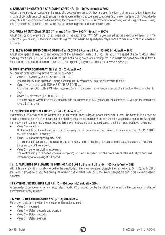
4. SENSIVITY ON OBSTACLE AT SLOWING SPEED SEL (0 – 100%) default = 60%Adjust the sensitivity on obstacle in the areas of slowdown in order to achieve a proper functioning of the automation, intervening in case of obstacle but such as to ensure handling even in the worst operating conditions (e.g. winter, hardening of motors due to wear, etc.). It is recommended after adjusting the parameter to perform a full movement of opening and closing, before checking the intervention on obstacle. Lower values correspond to a greater thrust on the obstacle.
5-6. FULLY OPERATIONAL SPEED SPno and SPnc (50 – 100 %) default = 100%Adjust the speed to ensure the correct operation of the automation. With Spno you can adjust the speed when opening, while with Spnc you can adjust the speed when closing. You can adjust the speed percentage from a minimum of 50% to a maximum of 100%.
7-8. SLOW-DOWN SPEED DURING OPENING or CLOSING SPLo and SPLc (10-100 %) default = 30%Adjust slow speed to ensure correct operation of the automation. With SpLo you can adjust the speed of slowing down when opening, while with SpLc you can adjust the speed of slowing down when closing. You can adjust the speed percentage from a minimum of 10% to a maximum of 100% of the corrisponding fully operational speed ( Spno / Spnc ).
9. STEP-BY-STEP CONFIGURATION SbS (0 - 2) default = 0You can set three operating modes for the SS command: • Value 0 = normal (AP-ST-CH-ST-AP-ST-CH-…).
Typical Step-by-Step operation. During handling, an SS pressure causes the automation to stop. • Value 1 = alternated with STOP (AP-ST-CH-AP-ST-CH-…).
Alternating operation with STOP when opening. During the opening movement a pressure of SS involves the automation to stop.
• Valore 2 = alternated (AP-CH-AP-CH-…). The user has no way to stop the automation with the command of SS. By sending the command SS you get the immediate reversal of the gear.
10. BEHAVIOUR AFTER BLACKOUT blt (0 – 2) default = 0It determines the behavior of the control unit, on its restart, after taking off power (blackout). In case the boom is in an open or closed position at the time of the blackout, the handling after the restoration of the current will always take place at the full speed. If the boom is in an intermediate position, the first movement occurs at a reduced speed, until the mechanical stop is reached.• Value 0 = no action.
On the switch-on, the automation remains stationary until a user command is received. If the command is a STEP-BY-STEP, the first movement is opening.
• Value 1 = performs opening movement. The control unit, which has just restarted, autonomously start the opening procedure. In this case, the automatic closing times set are NOT considered.
• Value 2 = performs closing movement. The control unit, just restarted, controls an opening at a reduced speed until the boom reaches the vertical position, and immediately after closing at full speed.
11-12. AMPLITUDE OF SLOWING IN OPENING AND CLOSE LSIo and LSIc (0 – 100 %) default = 25%With this parameter it is possible to define the amplitude of the slowdowns and possibly their exclusion (LSI = 0). With LsIo the slowing amplitude is adjusted during the opening phase, while with LsIc the slowing amplitude during the closing phase is adjusted.
13 ANTISKID / EXTRA-TIME RUN ASL (0 – 300 seconds) default = 25%A parameter to compensate for any motor slip is added ASL seconds to the handling times to ensure the complete handling of automation in every situation.
14. HOW TO USE THE ENCODER ENC (0 – 3) default = 3Parameter to determine when the encoder of the motor is used.• Value 0 = not used.• Value 1 = Detect obstacle and position.• Value 2 = Detect obstacle.• Value 3 = Detect position.

English - 27 / 36 6-1622396 - rev. 4 - 21/12/2021
This menu allows a more detailed customization of some parameters. To enter, press and hold the “MENU” key for at least 5 seconds. To change the parameters proceed as indicated for the base menu.WARNING! - after 2 minutes of inactivity the control panel automatically exits the menu.
PARAMETER DESCRIPTIONDEFAULTCUSTOM
MIN MAX UM
1 IAO
Select input device for opening:0 = disabled1 = PH12 = PH23 = S14 = S2
0 0 4
2 IAC
Select input device for closing:0 = disabled1 = PH12 = PH23 = S14 = S25 = PH3/S3
0 0 5
3 IOMMode of activation of the opening (IAO > 0):0 = on commitment1 = on disengagement after commitment
0 0 1
4 ICMMode of activation of the closing (IAC > 0):0 = on commitment1 = on disengagement after commitment
0 0 1
5 PH1Polarity PH1 input:0 = NC contact1 = NO contact
0 0 1
6 PH2Polarity PH2 input:0 = NC contact1 = NO contact
0 0 1
7 S1Polarity S1 input:0 = NC contact1 = NO contact
0 0 1
8 S2Polarity S2 input:0 = NC contact1 = NO contact
0 0 1
9 PS3Polarity PH3 and S3 inputs:0 = NC contact1 = NO contact
0 0 1
10 OLM
Led output management mode in opening movement:0 = output disabled1 = LED fixed on and OFF at the end of the movement2 = LED fixed on and ON at the end of the movement3 = LED flashes and OFF at end of movement 4 = LED flashes and ON at end of movement
1 0 4
9.9 ADVANCED MENU

28 / 36 - English 6-1622396 - rev. 4 - 21/12/2021
PARAMETER DESCRIPTIONDEFAULTCUSTOM
MIN MAX UM
11 CLM
Led output management mode in closing movement:0 = output disabled1 = LED fixed on and OFF at the end of the movement2 = LED fixed on and ON at the end of the movement3 = LED flashes and OFF at end of movement 4 = LED flashes and ON at end of movement
1 0 4
12 bLM
Flashing mode of the Leds:0 = normal impulse1 = short impulse2 = normal and soft impulse3 = short and soft impulse4 = flashing softly
0 0 4
13 SnM
Mode of action of the current sensor:0 = no action1 = intervention on mechanical stop and obstacle2 = intervention on obstacle3 = intervention on mechanical stop
1 0 3
14 SIt Current sensor intervention time. 2 1 10 x100ms
15 Sdt Current sensor override time at cue. 15 0 30 x100ms
16 ibMAction to be performed on obstacle detection in closing:0 = brief inversion of movement1 = total opening
0 0 1
17 UrA Duration of the acceleration ramp (from 0 to SPn) 15 0 20 x100ms
18 drAO Duration of the slow-down ramp in the opening movement (from SPno to SPLo)
6 0 20 x100ms
19 draC Duration of the slow-down ramp in the closing movement (from SPnc to SPLc)
6 0 20 x100ms
20 tPh
Choice of devices to perform the functionality test:0 = no device to test1 = PH12 = PH23 = PH1 + PH24 = PH35 = PH3 + PH16 = PH3 + PH27 = PH3 + PH2 + PH1
0 0 7
21 FPrConfiguration of the flashing output:0 = fixed on1 = flashes
1 0 1
22 tPr Time of light flashing, before the movement start. 0 0 10 s

English - 29 / 36 6-1622396 - rev. 4 - 21/12/2021
PARAMETER DESCRIPTIONDEFAULTCUSTOM
MIN MAX UM
23 deADEAD-MAN MODE:0 = disabled1 = enabled
0 0 1
24 SErCycle threshold for assistance request. Once the threshold is reached, the next cycles will be executed with fast flashing (if Fpr is active).0 = disabled
0 0 100x1000cicli
25 SEfEnabling continuous flashing for assistance request (function performed only with closed automation):0 = disabled1 = enabled
0 0 1
26 SFtDuration of the motor stop ramp, in case of immediate stop due to alarms or protections. Not considered in case of wired STOP command.
3 0 20 x100ms
27 EnP Time of encoder. 7 4 80 ms
28 dEF Setting the default values (RESET) 0 0 0
29 TRS Display single transmitter memory position.
30 trC Delete single transmitter.
31 trFAll radio memory erased. Enter to change the parameter and then hold down the «MENU» key, a countdown appears and ends with the word don.
32 SId Not in use
1. SELECT INPUT DEVICE FOR OPENING IAO (0 – 4) default = 0With this parameter you can select which photocell or loop controls the opening. WARNING! It is not possible to select PH3 or S3 for this function as they are reserved for detection of presence near the automation.• Value 0 = function disabled.• Value 1 = PH1 (photocell 1) command the opening.• Value 2 = PH2 (photocell 2) command the opening.• Value 3 = S1 (loop 1) command the opening.• Value 4 = S2 (loop 2) command the opening.
2. SELECT INPUT DEVICE FOR CLOSING IAC (0 – 5) default = 0With this parameter you can select which photocell or loop controls the closing. WARNING! If PH3 or S3 are selected for this function they, in addition to being able to control a closure on disengagement, will continue to function as security reversing the motion in case of intervention during the closing of the bar.• Value 0 = function disabled.• Value 1 = PH1 (photocell 1) command the closing.• Value 2 = PH2 (photocell 2) command the closing.• Value 3 = S1 (loop 1) command the closing.• Value 4 = S2 (loop 2) command the closing.• Value 5 = PH3 and S3 (security photocell and loop near the automation) command the closing after the transit.

30 / 36 - English 6-1622396 - rev. 4 - 21/12/2021
3. MODE OF ACTIVATION OF THE OPENING PROCEDURE IOM (0 – 1) default = 0If you have selected that an accessory commands the opening (IAO parameter) you can determine when this happens.• Value 0 = The opening procedure begins when entry is committed.• Value 1 = Once the commitment has been received in the selected entry, the opening procedure awaits the disengagement
of the same and then begins.
4. MODE OF ACTIVATION OF THE CLOSING PROCEDURE ICM (0 – 1) default = 0If you have selected that an accessory commands the closing (IAC parameter) you can determine when this happens.• Value 0 = The closing procedure begins when entry is committed.• Value 1 = Once the commitment has been received in the selected entry, the closing procedure awaits the disengagement
of the same and then begins.
5-6-7-8-9. POLARITY OF THE DEVICE INPUT PH1, PH2, S1, S2, PS3 (0 – 3) default = 0With these parameters it is possible to determine individually the polarity of the input connected to the control unit. With PS3 both the photocell PH3 and the magnetic loop S3 are set simultaneously.• Value 0 = Selected input device contact NC (Normally Close).• Value 1 = Selected input device contact NO (Normally Open).
10-11. CONFIGURATION OF LED OUTPUT WHILE THE AUTOMATION WORKS OLM and CLM (0 – 4) default = 1These parameters determine the operation of led strips during the opening (OLM) and the closing (CLM) movement.• Value 0 = Led output disabled.• Value 1 = FIXED ON LED lights during movement and LED OFF at the end of movement.• Value 2 = FIXED ON LED lights during movement and LED ON at the end of movement.• Value 3 = FLASHING LED during movement and OFF at the end of movement.• Value 4 = FLASHING LED during movement and ON at the end of movement.
12. CONFIGURATION OF LED FLASHING MODE bLM (0 – 4) default = 0Selection of the type of flashing carried out by the Leds, on a cycle time of total 500ms.• Value 0 = normal impulse (250ms ON – 250ms OFF).• Value 1 = short impulse (125ms ON – 375ms OFF).• Value 2 = normal and soft impulse (250ms ON – 250ms ramp to OFF).• Value 3 = short and soft impulse (125ms ON – 375ms ramp to OFF).• Value 4 = flashing softly (250ms ramp to ON – 250ms ramp to OFF).
13. MODE OF ACTION OF THE CURRENT SENSOR SnM (0 – 3) default = 1With this parameter you select when you want the current sensor to intervene.• Value 0 = No intervention to be carried out.• Value 1 = Complete intervention on mechanical stops and intervention on obstacle during all the amplitude of the movement.• Value 2 = Intervention only on obstacle during the movement.• Value 3 = Intervention only on mechanical stops.
14. CURRENT SENSOR INTERVENTION TIME SIt (1 – 10 x 100ms) default = 2Time beyond which the stationary motor sensing sensor (current sensor) intervenes in the presence of an obstacle.
15. CURRENT SENSOR OVERRIDE TIME AT CUE Sdt (0 – 30 x 100ms) default = 15Time while the current sensor is disabled at motor start-up.
16. ACTION TO BE PERFORMED ON OBSTACLE DETECTION IN CLOSINGibM (0 – 1) default = 0Behaviour of the control unit after detecting an obstacle in the closing phase.• Value 0 = Stops automation and commands a brief opening.• Value 1 = Stops automation and commands a full opening.
17. ACCELERATION RAMP UrA (0 – 20 *100ms) default = 15This parameter allows you to set the duration of the acceleration ramp during the start of the motor (time to get from 0 to Spn). The higher the value, the longer the ramp. With Ura = 0, ramps are deactivated and the motor starts abruptly at full speed.

English - 31 / 36 6-1622396 - rev. 4 - 21/12/2021
18-19. SLOW-DOWN RAMP drAO and drAC (0 – 20 x 100ms) default = 6This parameter allows you to set the duration of the slowdown ramp (time to get from Spn to SPL). With drAO you can change the ramp that takes place in the opening, while with DraC you can change the ramp that takes place in the closing of the automation. The higher the value, the longer the ramp. With dra = 0, ramps are deactivated and the motor changes abruptly from full speed to slow-down speed.
20. DEVICES FUNCTIONALITY TEST tPh (0 – 7) default = 0It gives you the option to choose which devices to test on. Enabling the test function is carried out the functional verification of the same before each movement that starts with stationary automation. WARNING! It is not performed in the case of fast reversals.• Value 0 = No device to test.• Value 1 = Test on PH1.• Value 2 = Test on PH2.• Value 3 = Test on PH1 and PH2.• Value 4 = Test on PH3.• Value 5 = Test on PH3 and PH1.• Value 6 = Test on PH3 and PH2.• Value 7 = Test on PH3, PH2 and PH1.
21. CONFIGURATION OF THE FLASHING OUTPUT FPr (0 – 1) default = 1Two modes are selectable for the flashing output: • Value 0 = The output remains fixed. You will need to use a flashing light device with auto flashing circuit (B.RO LIGHT 24 Vac).• Value 1 = Flashing output. You will need to use a flashing light device without auto flashing circuit (B.RO LIGHT FIX 24 Vac). 22. TIME OF FLASHING BEFORE MOVEMENT TPr (0 – 10 seconds) default = 0Flashing of the light before every movement, whose duration is defined by the parameter tpr.
23. DEAD-MAN MODE dEA (0 – 1) default = 0In DEAD-MAN mode, the automation moves exclusively until the control is present; at the release, the automation stops.The enabled commands are OPEN and CLOSE. The SS command is inactive. All automatic operations, including short or total reversals, are disabled. All security is disabled except the STOP.
24. CYCLE THRESHOLD FOR ASSISTANCE REQUEST Ser (0 – 100 x 1000 cicles) default = 0You can set from the menu the number of cycles expected before the control unit requires assistance. The request is signalled by replacing the normal functional flashing with a fast flashing during handling (only if fpr = 1).
25. CONTINUOUS FLASHING FOR ASSITANCE REQUEST SEF (0 – 1) default = 1Enabling the function requires the flashing light to continue flashing with automation closed as a service request.
26. DURATION OF THE MOTOR STOP RAMP SFt (0 – 20 x 100 ms) default = 3Duration of the ramp to switch from a state of movement to the complete stop of the automation, in case an immediate stop is required (alarm or protection events). WARNING! - this parameter is not considered in case of STOP intervention by wired command.
27. TIME OF ENCODER EnP (4 – 80 ms) default = 7Encoder output pulse length at motor speed.
28. SETTING THE DEFAULT VALUE (RESET) dEFBy accessing the def entry you can restore the factory configuration of the plant. The reset affects all the parameters of the base menu and the advanced menu while it does not affect the width of the learned movement of the boom.To reset access the def item, then confirm with the extended press of the “MENU” button. Hold down the “MENU” button until the number 0 flashes, release the button. Press and hold the “MENU” key. It starts a countdown “d80, d79, ... , d01” and when it is finished the reset is executed and the word done is displayed.
29. DISPLAY SINGLE TRANSMITTER MEMORY POSITION TRSBy accessing the Trs entry you can view the memory location where a transmitter has been stored. To perform the function access the item, then confirm with the extended press of the “MENU” button.Hold down until the SEE print display, release the button.

32 / 36 - English 6-1622396 - rev. 4 - 21/12/2021
At this point press a button of the stored transmitter (does not activate any command).The display shows the position in the memory for 2 seconds if it was stored; otherwise the not word is print in the display for 2 seconds if it was not stored.After 2 seconds the display returns to the SEE screen and you can run the function with another transmitter.To exit the function press the “MENU” button, otherwise after 15 seconds without transmissions the control panel exits the function showing the word tout on display.
30. DELETING SINGLE TRANSMITTER TRCBy accessing the trc voice you can erase a single stored transmitter from memory. To perform the function access the item, then confirm with the extended press of the “MENU” button.Hold down until the display prints the value 0, release the button. Select the location in the transmitter’s memory. Press and hold the “MENU” button until the display prints CLr, release the button.To exit the function, briefly press the “MENU” button. If ERR appears on display, there are problems with the memory (for example, empty position or disconnected memory).
31. ERASE ALL RADIO MEMORY trFBy accessing the trf menu entry you can delete all the transmitters learned. To reset access the item, then confirm with the extended press of the “MENU” button.Hold down until the display prints the value 0, release the button. Press and hold the “MENU” button again, starts a countdown “d80, d79, ... , d01” finished which reset is executed and don is displayed.
31. PARAMETER SIdParameter not in use.
9.10 ADJUSTMENT OF BOOM MOVEMENTFor a correct adjustment of the movement of the boom take into account the operation of the following parameters:
• SPnc = fully operational speed• SPLc = slow down speed• LSIc = amplitude of the slow down area• drac = time to switch from SPno to the slow down speed
WARNING! The parameters and the drawing refer to the closing movement of the boom.
LSIc
drac [sec]
SPLc
SPnc

English - 33 / 36 6-1622396 - rev. 4 - 21/12/2021
The control unit has a system that allows you to determine whether the power supply is present or not. In case the power supply is missing, and is installed the BATTERY KIT the control unit goes in a mode of energy saving.In these conditions, in fact, the control unit reduces the speed of the motor to 50%, disables all accessories outputs, excludes photocell tests, disables the opening and closing functions via command on photocell inputs and magnetic loops. In addition, the Leds in the situations in which it is expected to be on, will only be flashed briefly.In case then the battery level should drop below 12V, the motor speed is set to 100% to ensure the correct movement of the boom.When the presence of the mains voltage is detected again, the control unit is placed in normal operating conditions going to restore all the aforementioned functions that had been disabled or modified.
+24V TX photocells supply disabled
Photocells functionality test disabled
Opening/closing from input devices (IAO / IAC) disabled
Led fixed on substitute with briefly flashing
Flash output pwm 30%
Motor speed (battery level > 12V) 50%
Motor speed (battery level < 12V) 100%
9.11 OPERATIVITY OF THE AUTOMATION WITH BATTERY SUPPLY
It is possible to install a timer (not included) at the control unit to ensure that the boom is kept in the position of OPEN for a long period of time during the day according to your needs. To do this connect the device with a contact NORMALLY OPEN to the OPEN input of the control unit. In this way, when the contact is closed the control unit will command an opening of the barrier and as long as this contact remains closed, the BOOMY will remain in the position of OPEN.Upon release of the contact the barrier will not close immediately autonomously, but you will need to set an automatic closing time via the base menu, or give a command CLOSE or STEP-BY-STEP.
9.12 OPERATIVITY OF THE AUTOMATION WITH TIMER
11 12 13 14 15 16 17

34 / 36 - English 6-1622396 - rev. 4 - 21/12/2021
10. RESOLVING PROBLEMS
The anomalies, or error states, are reported by turning on both red and green Leds (if the LED strips are installed) and displaying a message in the display of the control unit.In case of alarm/error of the control unit, the LED outputs are managed in fixed mode and not following the settings of the OLM, CLM and blm parameters.
DISPLAY DESCRIPTION
eme Memory error: External memory not mounted or not recognized.
eex Memory write error: x is a number from 1 to 6. In case of error please contact technical support.
efO Intervention of impact sensor.
ebS Thermal intervention to protect the control unit.
eph Photocells malfunctions.
eth Thermal intervention to protect the control unit.
fuL Empty aviable storage space in external memory.
err Memory error during position display functions or individual transmitter deletion.
11. DECLARATION OF CONFORMITY
Manufacturer: Allmatic srlAddress: Via dell’Artigiano, 1 - 32026 Borgo Valbelluna (BL) ItaliaTelephone: +39 0437 751175E-mail: [email protected] site: www.allmatic.com
We declare under our responsibility that BOOMY operator is conforming to the following standard:2014/35/EU - Low Voltage Directive2014/30/EU - Electromagnetic Compatibility Directive2014/53/UE - Radio Equipment Directive
This product can not work alone and was designed to be fitted into a system made up of various other elements. Hence, it falls within Article 6, Paragraph 2 of the EC¬Directive 2006/42 (Machines) and following modifications, to which respect we point out the ban on its putting into service before being found compliant with what is provided by the Directive.This statement is provided in a shorter form for graphic reasons. The full version is available by contacting the manufacturer.

English - 35 / 36 6-1622396 - rev. 4 - 21/12/2021
This product is an integral part of automation, and therefore must be disposed of together with it. As with installation operations, even at the end of the life of this product, dismantling operations must be carried out by qualified personnel. This product consists of various types of materials: some can be recycled, others must be disposed of. Find out about the recycling or disposal systems required by the regulations in force in your territory for this category of product.
WARNING! - certain parts of the product may contain pollutants or dangerous substances which, if dispersed in the environment, could have harmful effects on the environment and human health.As indicated by the symbol on the side, it is forbidden to throw this product into household waste. Then perform the “separate collection” for disposal, according to the methods provided by the regulations in force in your territory, or return the product to the seller when buying a new equivalent product.WARNING! - the regulations in force at local level may provide for heavy penalties in case of improper disposal of this product.
13. PRODUCT DISPOSAL
14. WARRANTY
The manufacturer’s warranty is valid from the date stamped on the product and is limited to the repair or replacement free of charge of the parts recognized by the same as defective due to lack of essential quality in the materials or lack of processing. The warranty does not cover damage or defects due to external agents, maintenance deficiency, overload, natural wear, choice of incorrect type, assembly error, or other causes not attributable to the manufacturer. Tampered products will not be guaranteed or repaired. The data given are purely indicative. No liability may be charged for reductions in scope or malfunctions due to environmental interference. The liability of the manufacturer for damage caused to anyone by accidents of any nature caused by our defective products, are only those that derive from the Italian law.
12. MAINTENANCE
To be carried out only by specialized personnel after having removed the power to the motor.For the following operations please refer to chapter “5.6 MECHANICAL FINISHING AND ADJUSTMENTS”.
Every 100,000 complete manoeuvres check:- the balance of the boom.- tightening of the “U” shape profile that holds the boom to the hub.- wear and adjustment of the mechanical stops.
The maintenance described above is vital for the proper functioning of the product over time.

ALLMATIC S.r.l32026 Borgo Valbelluna - Belluno – ItalyVia dell’Artigiano, n°1 – Z.A.Tel. 0437 751175 – 751163 r.a. Fax 0437 751065www.allmatic.com - E-mail: [email protected]