Boolean Algebra and Logic gates · easier to fabricate and are the basic gates used in all IC...
25
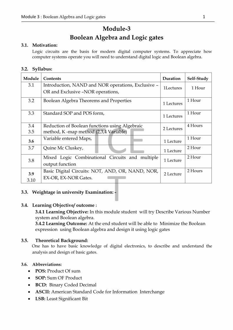
TCE T Module 3 : Boolean Algebra and Logic gates 1 Module-3 Boolean Algebra and Logic gates 3.1. Motivation: Logic circuits are the basis for modern digital computer systems. To appreciate how computer systems operate you will need to understand digital logic and Boolean algebra. 3.2. Syllabus: Module Contents Duration Self-Study 3.1 Introduction, NAND and NOR operations, Exclusive – OR and Exclusive –NOR operations, 1Lectures 1 Hour 3.2 Boolean Algebra Theorems and Properties 1 Lectures 1 Hour 3.3 Standard SOP and POS form, 1 Lectures 1 Hour 3.4 3.5 Reduction of Boolean functions using Algebraic method, K -map method (2,3,4 Variable) 2 Lectures 4 Hours 3.6 Variable entered Maps, 1 Lecture 1 Hour 3.7 Quine Mc Cluskey, 1 Lecture 2 Hour 3.8 Mixed Logic Combinational Circuits and multiple output function 1 Lecture 2 Hour 3.9 3.10 Basic Digital Circuits: NOT, AND, OR, NAND, NOR, EX-OR, EX-NOR Gates. 2 Lecture 2 Hours 3.3. Weightage in university Examination: - 3.4. Learning Objective/ outcome : 3.4.1 Learning Objective: In this module student will try Describe Various Number system and Boolean algebra. 3.4.2 Learning Outcome: At the end student will be able to Minimize the Boolean expression using Boolean algebra and design it using logic gates 3.5. Theoretical Background: One has to have basic knowledge of digital electronics, to describe and understand the analysis and design of basic gates. 3.6. Abbreviations: POS: Product Of sum SOP: Sum OF Product BCD: Binary Coded Decimal ASCII: American Standard Code for Information Interchange LSB: Least Significant Bit
Transcript of Boolean Algebra and Logic gates · easier to fabricate and are the basic gates used in all IC...
TCET
Module 3 : Boolean Algebra and Logic gates 1
Module-3
Boolean Algebra and Logic gates 3.1. Motivation:
Logic circuits are the basis for modern digital computer systems. To appreciate how computer systems operate you will need to understand digital logic and Boolean algebra.
3.2. Syllabus:
Module Contents Duration Self-Study
3.1
Introduction, NAND and NOR operations, Exclusive –
OR and Exclusive –NOR operations, 1Lectures 1 Hour
3.2 Boolean Algebra Theorems and Properties 1 Lectures
1 Hour
3.3 Standard SOP and POS form, 1 Lectures
1 Hour
3.4 3.5
Reduction of Boolean functions using Algebraic method, K -map method (2,3,4 Variable)
2 Lectures 4 Hours
3.6 Variable entered Maps,
1 Lecture 1 Hour
3.7 Quine Mc Cluskey, 1 Lecture
2 Hour
3.8 Mixed Logic Combinational Circuits and multiple
output function 1 Lecture
2 Hour
3.9
3.10
Basic Digital Circuits: NOT, AND, OR, NAND, NOR,
EX-OR, EX-NOR Gates. 2 Lecture
2 Hours
3.3. Weightage in university Examination: -
3.4. Learning Objective/ outcome :
3.4.1 Learning Objective: In this module student will try Describe Various Number system and Boolean algebra. 3.4.2 Learning Outcome: At the end student will be able to Minimize the Boolean expression using Boolean algebra and design it using logic gates
3.5. Theoretical Background: One has to have basic knowledge of digital electronics, to describe and understand the
analysis and design of basic gates.
3.6. Abbreviations:
POS: Product Of sum
SOP: Sum OF Product
BCD: Binary Coded Decimal
ASCII: American Standard Code for Information Interchange
LSB: Least Significant Bit

MSB: Most Significant Bit
LSD: Least Significant Digit
MSD: Most Significant Digit
3.7. Key Definitions:
Karnaugh maps: A mapping technique used to minimize logical expression
Minterm: A logical term consisting of all the literals in the ANDed form.
Maxterm: A logical term consisting of all the literals in the ORed form in the logic
function
Canonical Form: A term used to describe a Boolean function that is written either as
a sum of minterms, or as a product of maxterms. For example, using three variables
A, B, and C, the equation f (A, B, C) = A(B ~ C) + ABC
Product of Sum (POS): A logical expression in the form of ORed terms ANDed
together
Sum of Product (SOP): A logical expression in the form of ANDed terms ORed
together
Literal: A Literal is a Boolean Variables or its complement
Combinational logic: The logic in which the outputs at any instant of time are dependent only on the inputs present at that time
Standard POS: If each term in POS form contains all the literals then the POS form is known as standard or canonical POS form
Standard SOP: If each term in SOP form contains all the literals then the SOP form is
known as standard or canonical SOP form.
Don’t care: A minterm/maxterm in a logic function may or may not be included.
Essential Prime implicants: A tern in SOP form in a logic function that must be present in the minimal expression.
3.8 Introduction
3.8.1 Basic Logic Gates
The term ‘Gate’ is used to describe the members of a set of basic electronic
components which, when combined with each other, are able to perform complex
logical and arithmetic operations. 'Gates' are the physical realization of the simple
Boolean expressions.
AND Gate:
The AND gate is a circuit which gives a high output (logic 1) if all its inputs are
high. Otherwise the output will be low (logic 0).

TCET
Module 3 : Boolean Algebra and Logic gates 3
Fig 3.1
A B AB
0 0 0
0 1 0
1 0 0
1 1 1
Table 3.1
OR Gate:
The OR gate is a circuit which
gives a high output (logic 1) if
any one of the inputs is high.
Otherwise the output will be
low
Fig 3.2
A B A+B
0 0 0
0 1 1
1 0 1
1 1 1
Table 3.2
NOT Gate:
Fig 3.3
The NOT gate is a circuit
which produces at its output
the negated (inverted) version
of its input logic. The circuit is
also known as an inverter.
A NOT
0 1
1 0
NAND Gate: Table 3.3
The NAND gate is a NOT-AND
circuit which is equivalent to an
AND circuit followed by a NOT

circuit. The output of the NAND
gate is high if any of its inputs is
low.
Fig 3.4
A B NOT(AB)
0 0 1
0 1 1
1 0 1
1 1 0
Table 3. 4
NOR Gate:
The NOR gate is a NOT-OR
circuit which is equivalent to an
OR circuit followed by a NOT
circuit. The output of the NOR
gate is low if any of its inputs is
high.
A B NOT
(A+B)
0 0 1
0 1 0
1 0 0
1 1 0
Fig 3.5 Table 3.5
Exclusive-OR Gate (EOR):
Fig 3.6
The Exclusive-OR (EOR) gate
is a circuit which gives a high
output if either of its two
inputs is high, but not both. A
encircled plus sign ( ) is used
to indicate the EOR operation.
A B A
B
0 0 0
0 1 1
0 1

TCET
Module 3 : Boolean Algebra and Logic gates 5
1
1 1 0
Table 3.6
Universal Gates:
A universal gate is a gate which can implement any Boolean function without
need to use any other gate type. The NAND and NOR gates are universal gates.
In practice, this is advantageous since NAND and NOR gates are economical and
easier to fabricate and are the basic gates used in all IC digital logic families. In
fact, an AND gate is typically implemented as a NAND gate followed by an
inverter not the other way around!! Likewise, an OR gate is typically
implemented as a NOR gate followed by an inverter not the other way around!!
NAND Gate is a Universal Gate:
To prove that any Boolean function can be implemented using only NAND gates,
we will show that the AND, OR, and NOT operations can be performed using
only these gates.
Implementing an Inverter Using only NAND Gate
The figure shows two ways in which a NAND gate can be used as an inverter
(NOT gate).
1. All NAND input pins connect to the input signal A gives an output A’.
Fig 3.7
2. One NAND input pin is connected to the input signal A while all other input
pins are connected to logic 1. The output will be A’.
Fig 3.8
3. Implementing AND Using only NAND Gates
An AND gate can be replaced by NAND gates as shown in the figure (The AND
is replaced by a NAND gate with its output complemented by a NAND gate
inverter).
Fig 3.9

4. Implementing OR Using only NAND Gates
An OR gate can be replaced by NAND gates as shown in the figure (The OR gate
is replaced by a NAND gate with all its inputs complemented by NAND gate
inverters).
Fig 3.10
Thus, the NAND gate is a universal gate since it can implement the AND, OR
and NOT functions.
NOR Gate is a Universal Gate:
To prove that any Boolean function can be implemented using only NOR gates,
we will show that the AND, OR, and NOT operations can be performed using
only these gates.
1. Implementing an Inverter Using only NOR Gate
The figure shows two ways in which a NOR gate can be used as an inverter (NOT
gate).
1. All NOR input pins connect to the input signal A gives an output A’.
Fig 3.11
2. One NOR input pin is connected to the input signal A while all other input pins are
connected to logic 0. The output will be A’.
Fig 3.12
3. Implementing OR Using only NOR Gates
An OR gate can be replaced by NOR gates as shown in the figure (The OR is
replaced by a NOR gate with its output complemented by a NOR gate inverter)
Fig 3.13
4. Implementing AND Using only NOR Gates
An AND gate can be replaced by NOR gates as shown in the figure (The AND
gate is replaced by a NOR gate with all its inputs complemented by NOR gate
inverters)

TCET
Module 3 : Boolean Algebra and Logic gates 7
Fig 3.14
Thus, the NOR gate is a universal gate since it can implement the AND, OR and
NOT functions.
Boolean algebra consists of binary variables and logical operations. Variables:
letters, such as A, B, C, d, W, x, y, z, etc. having two distinct possible values 1 and
0.
Logical operations: AND, OR and NOT
AND: represented by a dot or the absence of an operator. x . y=z or xy=z, this
reads: "x AND y is equal to z”. It means that z=1 if and only if [x=1 and y=1;
otherwise z=0]
OR: represented by a plus sign. x + y=z , is read "x OR y equals to z". it means
that z=1 if either [x=1 or y=1; if both are zero then z=0]
NOT: represented by a prime or a bar. x'=z , reads "not x equals to z". it means
that if x=1 then z=0 or if x=0 then z=1.
These Logical Operations are digital circuits constructed from diodes, transistors,
and resistors connected in such a way that the circuit output is the result of a
basic logic operation performed on the inputs.
B) Truth Table is a table of all possible combinations of the variables showing the
relation between the values that variables may take and the result of the
operation. In another way one can say a truth table is a means for describing how
a logic circuit's output depends on the logic levels present at the circuit's inputs.
The following is truth table example of a two input logic circuit,
Input
1
Input
2 Output
X Y Z = X ?
Y
0 0 0
0 1 0
1 0 0

1 1 1
Table 3.7
Since the output Z is 1 only if X and Y are 1, therefore, the "?" is an AND gate.
C) Boolean Identities are used to designate the function, dictates the
interconnection of gates in the logic circuit diagram. By manipulating Boolean
expression according to Boolean algebraic rules. It is possible to obtain a simpler
expression with the same function. such manipulation will reduce the number of
gates the number of inputs to the gates.
Using the relations defined in the AND, OR and NOT operation, a number of
identities are stated.
Group A Group B
1 X + 0 = X X . 1 = X
2 X + 1 = 1 X . 0 = 0
3 X + X = X X . X = X
4 X + X' = 1 X . X' = 0
5 (X')' = X
6 Commutative X+Y = Y+X XY = YX
7 Associative X+(Y+Z)=
(X+Y)+Z
X(YZ) =
(XY)Z
8 Distributive X (Y + Z) =
XY + X Z
X + YZ =
(X + Y)(X +
Z)
9 DeMorgan's
Theorem (X+Y)'=X'Y' (XY)'=X'+Y'
Table 3.8
D) Duality Principle: Every algebraic expression deducible from the identities of
Boolean algebra remains valid if the operators and the identitiy elements are
interchanges.
Dual of an expression: Interchange OR and AND operators and replace 1's by 0's
and 0's by 1's
An Equation in one column can be obtained from the corresponding equation in
the other column by taking the dual of the expressions.
3.8.3. Standard SOP and POS form, Reduction of Boolean functions using Algebraic
method, K -map method (2, 3, 4 Variable).

TCET
Module 3 : Boolean Algebra and Logic gates 9
Since there are a finite number of Boolean functions of n input variables, yet an infinite
number of possible logic expressions you can construct with those n input values, clearly
there are an infinite number of logic expressions that are equivalent (i.e., they produce the
same result given the same inputs). To help eliminate possible confusion, logic designers
generally specify a Boolean function using a canonical, or standardized, form. For any given
Boolean function there exists a unique canonical form. This eliminates some confusion
when dealing with Boolean functions.
Actually, there are several different canonical forms. We will discuss only two here and
employ only the first of the two. The first is the so-called sum of minterms and the second is
the product of maxterms. Using the duality principle, it is very easy to convert between these
two. A term is a variable or a product (logical AND) of several different literals. For
example, if you have two variables, A and B, there are eight possible terms: A, B, A’, B’,
A’B’,A’B, AB’, and AB. For three variables we have 26 different terms: A, B, C, A’, B’, C’,
A’B’, A’B, AB’, AB, A’C’, A’C, AC’, AC, B’C’, B’C, BC’, BC, A’B’C’, AB’C’, A’BC’, ABC’,
A’B’C AB’C, A’BC, and ABC. As you can see, as the number of variables increases, the
number of terms increases dramatically. A minterm is a product containing exactly n
literals. For example, the minterms for two variables are A’B’, AB’, A’B, and AB. Likewise,
the minterms for three variables A, B, and C are A’B’C’, AB’C’, A’BC’, ABC’, A’B’C, AB’C,
A’BC, and ABC. In general, there are 2n minterms for n variables. The set of possible
minterms is very easy to generate since they correspond to the sequence of binary numbers:
Binary
Equivalent
Minterm
000 A’ B’ C’
001 A’ B’ C
010 A’ B C’
011 A’ B C
100 A B’ C’
101 A B’ C
110 A B C’
111 A B C
Table 3.9 Minterms for Three Input Variables
We can specify any Boolean function using a sum (logical OR) of minterms. Given F248
=AB+C the equivalent canonical form is ABC+A’BC+AB’C+A’B’C+ABC’. Algebraically, we
can show that these two are equivalent as follows:
ABC+A’BC+AB’C+A’B’C+ABC’ = BC (A+A’) + B’C (A+A’) + ABC’
= BC•1 +B’C•1 + ABC’
= C(B+B’) + ABC’
= C + ABC’
= C + AB

Obviously, the canonical form is not the optimal form. On the other hand, there is a big
advantage to the sum of minterms canonical form: it is very easy to generate the truth table
for a function from this canonical form. Furthermore, it is also very easy to generate the
logic equation from the truth table. To build the truth table from the canonical form, simply
convert each minterm into a binary value by substituting a “1” for unprimed variables and
a “0” for primed variables. Then place a “1” in the corresponding position (specified by the
binary minterm value) in the truth table:
1) Convert minterms to binary equivalents:
F248= CBA + CBA’ + CB’A + CB’A’ + C’BA
= 111 + 110 + 101 + 100 + 011
2) Substitute a one in the truth table for each entry above. Finally, put zeros in all the entries
that you did not fill with ones in the first step above
Table 3.10: Creating a Truth Table from Minterms, Step One
Table 3.11: Creating a Truth Table from Minterms, Step Two
Going in the other direction, generating a logic function from a truth table, is almost as
easy. First, locate all the entries in the truth table with a one. In the table above, these are
the last five entries. The number of table entries containing ones determines the number of
minterms in the canonical equation. To generate the individual minterms, substitute A, B,
or C for ones and A’, B’, or C’ for zeros in the truth table above. Then compute the sum of
these items. In the example above, F248 contains one for CBA = 111, 110, 101, 100, and 011.
Therefore, F248 = CBA + CBA’ + CB’A + CB’A’ + C’AB. The first term, CBA, comes from the

TCET
Module 3 : Boolean Algebra and Logic gates 11
last entry in the table above. C, B, and A all contain ones so we generate the minterm CBA
(or ABC, if you prefer). The second to last entry contains 110 for CBA, so we generate the
minterm CBA’. Likewise, 101 produce CB’A; 100 produce CB’A’ and 011 produces C’BA. Of
course, the logical OR and logical AND operations are both commutative, so we can
rearrange the terms within the minterms as we please and we can rearrange the minterms
within the sum as we see fit. This process works equally well for any number of variables.
Consider the function F53504 = ABCD + A’BCD + A’B’CD + A’B’C’D. Placing ones in the
appropriate positions in the truth table generates the following:
D C B A F = ABCD + A’BCD
+ A’B’CD +
A’B’C’D
0 0 0 0
0 0 0 1
0 0 1 0
0 0 1 1
0 1 0 0
0 1 0 1
0 1 1 0
0 1 1 1
1 0 0 0 1
1 0 0 1
1 0 1 0
1 0 1 1
1 1 0 0 1
1 1 0 1
1 1 1 0 1
1 1 1 1 1
Table 3.12: Creating a Truth Table with Four Variables from Minterms
The remaining elements in this truth table all contain zero.
Perhaps the easiest way to generate the canonical form of a Boolean function is to first
generate the truth table for that function and then build the canonical form from the truth
table. We’ll use this technique, for example, when converting between the two canonical
forms this chapter presents. However, it is also a simple matter to generate the sum of
minterms form algebraically. By using the distributive law and theorem 15 (A + A’ = 1)
makes this task easy. Consider F248 = AB + C. This function contains two terms, AB and C,
but they are not minterms. Minterms contain each of the possible variables in a primed or
unprimed form. We can convert the first term to a sum of minterms as follows:
AB = AB • 1 By Th4
= AB • (C + C’) By Th 15
= ABC + ABC’ By distributive law
= CBA + C’BA By associative law

Similarly, we can convert the second term in F248 to a sum of minterms as follows:
C = C • 1 By Th4
= C • (A + A’) By Th15
= CA + CA’ By distributive law
= CA•1 + CA’•1 By Th4
= CA • (B + B’) + CA’ • (B + B’) By Th15
= CAB + CAB’ + CA’B + CA’B’ By distributive law
= CBA + CBA’ + CB’A + CB’A’ By associative law
The last step (rearranging the terms) in these two conversions is optional. To obtain the
final canonical form for F248 we need only sum the results from these two conversions:
F248 = (CBA + C’BA) + (CBA + CBA’ + CB’A + CB’A’)
= CBA + CBA’ + CB’A + CB’A’ + C’BA
Another way to generate a canonical form is to use products of maxterms. A maxterm is the
sum (logical OR) of all input variables, primed or unprimed. For example, considerthe
following logic function G of three variables:
G = (A+B+C) • (A’+B+C) • (A+B’+C).
Like the sum of minterms form, there is exactly one product of maxterms for each possible
logic function. Of course, for every product of maxterms there is an equivalent sum of
minterms form. In fact, the function G, above, is equivalent to
F248 = CBA + CBA’ + CB’A + CB’A’ + C’BA = AB +C.
Generating a truth table from the product of maxterms is no more difficult than building it
from the sum of minterms. You use the duality principle to accomplish this. Remember, the
duality principle says to swap AND for OR and zeros for ones (and vice versa).
Therefore, to build the truth table, you would first swap primed and non-primed literals. In
G above, this would yield:
G= (A’ + B’ + C’) • (A + B’ + C’) • (A’ + B + C’)
The next step is to swap the logical OR and logical AND operators. This produces
G = A’B’C’ + AB’C’ + A’BC’
Finally, you need to swap all zeros and ones. This means that you store zeros into the truth
table for each of the above entries and then fill in the rest of the truth table with ones. This
will place a zero in entries zero, one, and two in the truth table. Filling the remaining
entries with ones produces F248.
You can easily convert between these two canonical forms by generating the truth table for
one form and working backwards from the truth table to produce the other form. For
example, consider the function of two variables, F7 = A + B. The sum of minterms form is
F7 = A’B + AB’ + AB. The truth table takes the form:
Working backwards to get the product of maxterms, we locate all entries that have a zero
result. This is the entry with A and B equal to zero. This gives us the first step of G=A’B’.
However, we still need to invert all the variables to obtain G=AB. By the duality principle
we need to swap the logical OR and logical AND operators obtaining G=A+B.
This is the canonical product of maxterms form. Since working with the product of maxterms
is a little easier than working with sums of minterms, this text will generally use the sum of

TCET
Module 3 : Boolean Algebra and Logic gates 13
minterms form. Furthermore, the sum of minterms form is more common in boolean logic
work. However, you will encounter both forms when studying logic design.
3.8.4 Simplifications of Boolean Functions:
Since there are an infinite variety of Boolean functions of n variables, but only a finite
number of unique boolean functions of those n variables, you might wonder if there is
some method that will simplify a given boolean function to produce the optimal form. Of
course, you can always use algebraic transformations to produce the optimal form, but
using heuristics does not guarantee an optimal transformation. There are, however, two
methods that will reduce a given Boolean function to its optimal form: the map method and
the prime implicants method. In this text we will only cover the mapping method, see any
text on logic design for other methods.
Table 3.13: F7 (OR) Truth Table for Two Variables
Working backwards to get the product of maxterms, we locate all entries that have a zero
result. This is the entry with A and B equal to zero. This gives us the first step of G=A’B’.
However, we still need to invert all the variables to obtain G=AB. By the duality principle
we need to swap the logical OR and logical AND operators obtaining G=A+B. This is the
canonical product of maxterms form. Since working with the product of maxterms is a little
messier than working with sums of minterms, this text will generally use the sum of
minterms form. Furthermore, the sum of minterms form is more common in boolean logic
work. However, you will encounter both forms when studying logic design.
Since for any logic function some optimal form must exist, you may wonder why we don’t
use the optimal form for the canonical form. There are two reasons. First, there may be
several optimal forms. They are not guaranteed to be unique. Second, it is easy to convert
between the canonical and truth table forms.
Using the map method to optimize boolean functions is practical only for functions of two,
three, or four variables. With care, you can use it for functions of five or six variables, but
the map method is cumbersome to use at that point. For more than six variables,
attempting map simplifications by hand would not be wise1. The first step in using the
map method is to build a two-dimensional truth table for the function.
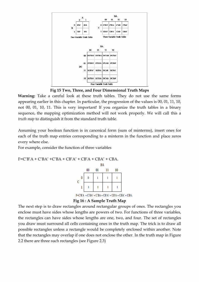
Fig 15 Two, Three, and Four Dimensional Truth Maps
Warning: Take a careful look at these truth tables. They do not use the same forms
appearing earlier in this chapter. In particular, the progression of the values is 00, 01, 11, 10,
not 00, 01, 10, 11. This is very important! If you organize the truth tables in a binary
sequence, the mapping optimization method will not work properly. We will call this a
truth map to distinguish it from the standard truth table.
Assuming your boolean function is in canonical form (sum of minterms), insert ones for
each of the truth map entries corresponding to a minterm in the function and place zeros
every where else.
For example, consider the function of three variables
F=C’B’A + C’BA’ +C’BA + CB’A’ + CB’A + CBA’ + CBA.
Fig 16 : A Sample Truth Map
The next step is to draw rectangles around rectangular groups of ones. The rectangles you
enclose must have sides whose lengths are powers of two. For functions of three variables,
the rectangles can have sides whose lengths are one, two, and four. The set of rectangles
you draw must surround all cells containing ones in the truth map. The trick is to draw all
possible rectangles unless a rectangle would be completely enclosed within another. Note
that the rectangles may overlap if one does not enclose the other. In the truth map in Figure
2.2 there are three such rectangles (see Figure 2.3)
TCET
Module 3 : Boolean Algebra and Logic gates 15
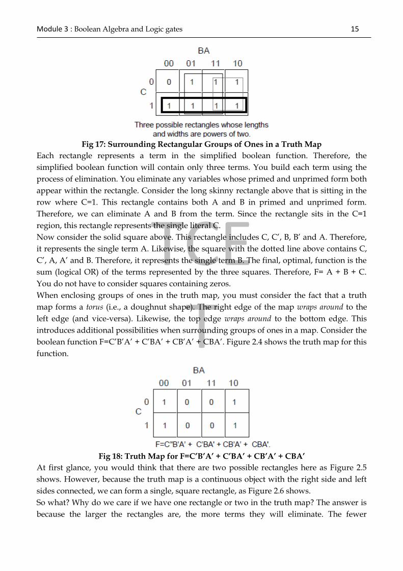
Fig 17: Surrounding Rectangular Groups of Ones in a Truth Map
Each rectangle represents a term in the simplified boolean function. Therefore, the
simplified boolean function will contain only three terms. You build each term using the
process of elimination. You eliminate any variables whose primed and unprimed form both
appear within the rectangle. Consider the long skinny rectangle above that is sitting in the
row where C=1. This rectangle contains both A and B in primed and unprimed form.
Therefore, we can eliminate A and B from the term. Since the rectangle sits in the C=1
region, this rectangle represents the single literal C.
Now consider the solid square above. This rectangle includes C, C’, B, B’ and A. Therefore,
it represents the single term A. Likewise, the square with the dotted line above contains C,
C’, A, A’ and B. Therefore, it represents the single term B. The final, optimal, function is the
sum (logical OR) of the terms represented by the three squares. Therefore, F= A + B + C.
You do not have to consider squares containing zeros.
When enclosing groups of ones in the truth map, you must consider the fact that a truth
map forms a torus (i.e., a doughnut shape). The right edge of the map wraps around to the
left edge (and vice-versa). Likewise, the top edge wraps around to the bottom edge. This
introduces additional possibilities when surrounding groups of ones in a map. Consider the
boolean function F=C’B’A’ + C’BA’ + CB’A’ + CBA’. Figure 2.4 shows the truth map for this
function.
Fig 18: Truth Map for F=C’B’A’ + C’BA’ + CB’A’ + CBA’
At first glance, you would think that there are two possible rectangles here as Figure 2.5
shows. However, because the truth map is a continuous object with the right side and left
sides connected, we can form a single, square rectangle, as Figure 2.6 shows.
So what? Why do we care if we have one rectangle or two in the truth map? The answer is
because the larger the rectangles are, the more terms they will eliminate. The fewer

rectangles that we have, the fewer terms will appear in the final boolean function. For
example, the former example with two rectangles generates a function with two terms. The
first rectangle (on the left) eliminates the C variable, leaving A’B’ as its term. The second
rectangle, on the right, also eliminates the C variable, leaving the term BA’.
Therefore, this truth map would produce the equation F=A’B’ + A’B. We know this is not
optimal, see Th 13. Now consider the second truth map above. Here we have a single
rectangle so our Boolean function will only have a single term. Obviously this is more
optimal than an equation with two terms. Since this rectangle includes both C and C’ and
also B and B’, the only term left is A’. This Boolean function, therefore, reduces to F=A’.
There are only two cases that the truth map method cannot handle properly: a truth map
that contains all zeros or a truth map that contains all ones. These two cases correspond to
the boolean functions F=0 and F=1, respectively. These functions are easy to generate by
inspection of the truth map.
Fig 19: First attempt at Surrounding Rectangles Formed by Ones
Fig 20: Correct Rectangle for the Function
An important thing you must keep in mind when optimizing Boolean functions using the
mapping method is that you always want to pick the largest rectangles whose sides lengths
are a power of two. You must do this even for overlapping rectangles (unless one rectangle
encloses another). Consider the boolean function F = C'B'A' + C'BA' + CB'A' +C'AB + CBA'
+ CBA. This produces the truth map appearing in Figure 2.7.The initial temptation is to
create one of the sets of rectangles found in Figure 2.8. However, the correct mapping
appears in Figure 2.9. All three mappings will produce a Boolean function with two terms.
However, the first two will produce the expressions F= B + A'B' and F = AB + A'. The third
form produces F = B + A'. Obviously, this last form is more optimal than the other two
forms (see theorems 11 and 12).
For functions of three variables, the size of the rectangle determines the number of terms it
represents:
• A rectangle enclosing a single square represents a minterm. The associated term will
have three literals.
• A rectangle surrounding two squares containing ones represents a term containing
two literals.

TCET
Module 3 : Boolean Algebra and Logic gates 17
• A rectangle surrounding four squares containing ones represents a term containing a
single literal.
• A rectangle surrounding eight squares represents the function F = 1.
Truth maps you create for functions of four variables are even trickier. This is because there
are lots of places rectangles can hide from you along the edges. Figure 2.10 shows some
possible places rectangles can hide.
Fig 21: Truth Map for F = C'B'A' + C'BA' + CB'A' + C'AB + CBA' + CBA
Fig 22: Obvious Choices for Rectangles
Fig 22 Correct Set of Rectangles for F = C'B'A' + C'BA' + CB'A' + C'AB + CBA' + CBA

Figure 23: Partial Pattern List for 4x4 Truth Map
This list of patterns doesn’t even begin to cover all of them! For example, these diagrams
show none of the 1x2 rectangles. You must exercise care when working with four variable
maps to ensure you select the largest possible rectangles, especially when overlap occurs.
This is particularly important with you have a rectangle next to an edge of the truth map.
As with functions of three variables, the size of the rectangle in a four variable truth map
controls the number of terms it represents:
• A rectangle enclosing a single square represents a minterm. The associated term will
have four literals.
• A rectangle surrounding two squares containing ones represents a term containing
three literals.
• A rectangle surrounding four squares containing ones represents a term containing
two literals.
• A rectangle surrounding eight squares containing ones represents a term containing
a single literal.
• A rectangle surrounding sixteen squares represents the function F=1.
This last example demonstrates an optimization of a function containing four variables. The
function is F = D’C’B’A’ + D’C’B’A + D’C’BA + D’C’BA’ + D’CB’A + D’CBA + DCB’A +
DCBA + DC’B’A’ + DC’BA’,. Here are two possible sets of maximal rectangles for this
function; each producing three terms .Both functions are equivalent; both are as optimal as
you can get2. Either will suffice for our purposes.
First, let’s consider the term represented by the rectangle formed by the four corners. This
rectangle contains B, B’, D, and D’; so we can eliminate those terms. The remaining terms
contained within these rectangles are C’ and A’, so this rectangle represents the term C’A’.
The second rectangle, common to both maps in, is the rectangle formed by the iddle four
squares. This rectangle includes the terms A, B, B’, C, D, and D’. Eliminating B, B’, D, and

TCET
Module 3 : Boolean Algebra and Logic gates 19
D’ (since both primed and unprimed terms exist), we obtain CA as the term for this
rectangle. The map on the left in Figure has a third term represented by the top row.
Thisterm includes the variables A, A’, B, B’, C’ and D’. Since it contains A, A’, B, and B’, we
can eliminate these terms. This leaves the term C’D’. Therefore, the function represented by
the map on the left is F=C’A’ + CA + C’D’.
The map on the right has a third term represented by the top/middle four squares. This
rectangle subsumes the variables A, B, B’, C, C’, and D’. We can eliminate B, B’, C, and C’
since both primed and unprimed versions appear, this leaves the term AD. Therefore, the
function represented by the function on the right is F=C’A’ + CA + AD’.
Since both expressions are equivalent, contain the same number of terms, and the same
number of operators, either form is equivalent. Unless there is another reason for choosing
one over the other, you can use either form.
3.8.7 Quine-McCluskey minimization method:
Quine-McCluskey minimization method uses the same theorem to produce the solution as
the K-map method, namely X(Y+Y')=X
Minimization Technique
The expression is represented in the canonical SOP form if not already in that form. The
function is converted into numeric notation.
The numbers are converted into binary form.
The minterms are arranged in a column divided into groups.
Begin with the minimization procedure.
Each minterm of one group is compared with each minterm in the group
immediately below.
Each time a number is found in one group which is the same as a number in
the group below except for one digit, the numbers pair is ticked and a new
composite is created.
This composite number has the same number of digits as the numbers in the
pair except the digit different which is replaced by an "x".
The above procedure is repeated on the second column to generate a third column.
The next step is to identify the essential prime implicants, which can be done using a
prime implicant chart.
Where a prime implicant covers a minterm, the intersection of the
corresponding row and column is marked with a cross.
Those columns with only one cross identify the essential prime implicants.
These prime implicants must be in the final answer.
The single crosses on a column are circled and all the crosses on the same row
are also circled, indicating that these crosses are covered by the prime
implicants selected.

Once one cross on a column is circled, all the crosses on that column can be
circled since the minterm is now covered.
If any non-essential prime implicant has all its crosses circled, the prime
implicant is redundant and need not be considered further.
Next, a selection must be made from the remaining nonessential prime implicants,
by considering how the non-circled crosses can be covered best.
One generally would take those prime implicants which cover the greatest
number of crosses on their row.
If all the crosses in one row also occur on another row which includes further
crosses, then the latter is said to dominate the former and can be selected.
The dominated prime implicant can then be deleted.
Example:
Find the minimal sum of products for the Boolean expression, f= (1,2,3,7,8,9,10,11,14,15),
using Quine-McCluskey method
Firstly these minterms are represented in the binary form as shown in the table below. The
above binary representations are grouped into a number of sections in terms of the number
of 1's as shown in the table below
Table 3.14 Binary representation of minterms
Minterm U V W X
1 0 0 0 1
2 0 0 1 0
3 0 0 1 1
7 0 1 1 1
8 1 0 0 0
9 1 0 0 1
10 1 0 1 0
11 1 0 1 1
14 1 1 1 0
15 1 1 1 1
No of
1’s
Minterm U V W X
1 1 0 0 0 1
1 2 0 0 1 0
1 8 1 0 0 0
2 3 0 0 1 1
2 9 1 0 0 1
2 10 1 0 1 0
3 7 0 1 1 1
TCET
Module 3 : Boolean Algebra and Logic gates 21
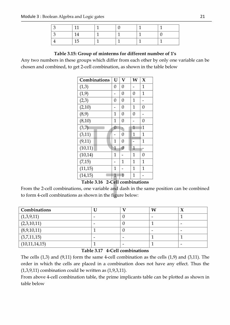
Table 3.15: Group of minterms for different number of 1's
Any two numbers in these groups which differ from each other by only one variable can be
chosen and combined, to get 2-cell combination, as shown in the table below
Combinations U V W X
(1,3) 0 0 - 1
(1,9) - 0 0 1
(2,3) 0 0 1 -
(2,10) - 0 1 0
(8,9) 1 0 0 -
(8,10) 1 0 - 0
(3,7) 0 - 1 1
(3,11) - 0 1 1
(9,11) 1 0 - 1
(10,11) 1 0 1 -
(10,14) 1 - 1 0
(7,15) - 1 1 1
(11,15) 1 - 1 1
(14,15) 1 1 1 -
Table 3.16 2-Cell combinations
From the 2-cell combinations, one variable and dash in the same position can be combined
to form 4-cell combinations as shown in the figure below:
Table 3.17 4-Cell combinations
The cells (1,3) and (9,11) form the same 4-cell combination as the cells (1,9) and (3,11). The
order in which the cells are placed in a combination does not have any effect. Thus the
(1,3,9,11) combination could be written as (1,9,3,11).
From above 4-cell combination table, the prime implicants table can be plotted as shown in
table below
3 11 1 0 1 1
3 14 1 1 1 0
4 15 1 1 1 1
Combinations U V W X
(1,3,9,11) - 0 - 1
(2,3,10,11) - 0 1 -
(8,9,10,11) 1 0 - -
(3,7,11,15) - - 1 1
(10,11,14,15) 1 - 1 -
Prime
Implicants 1 2 3 7 8 9 10 11 14 15
(1,3,9,11) X - X - - X - X - -
(2,3,10,11) - X X - - - X X - -
(8,9,10,11) - - - - X X X X - -
(3,7,11,15) - - - - - - X X X X
- X X - X X - - - X -
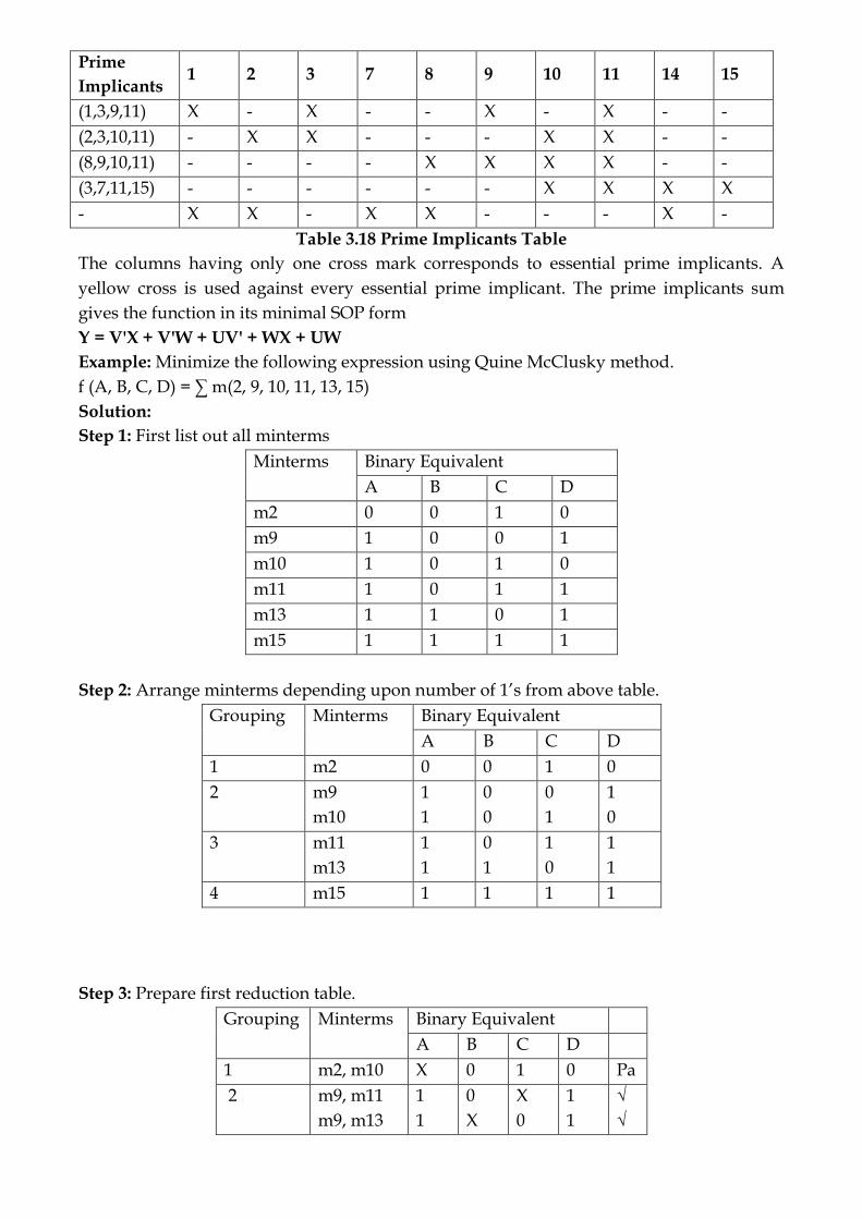
Table 3.18 Prime Implicants Table
The columns having only one cross mark corresponds to essential prime implicants. A
yellow cross is used against every essential prime implicant. The prime implicants sum
gives the function in its minimal SOP form
Y = V'X + V'W + UV' + WX + UW
Example: Minimize the following expression using Quine McClusky method.
f (A, B, C, D) = ∑ m(2, 9, 10, 11, 13, 15)
Solution:
Step 1: First list out all minterms
Minterms Binary Equivalent
A B C D
m2 0 0 1 0
m9 1 0 0 1
m10 1 0 1 0
m11 1 0 1 1
m13 1 1 0 1
m15 1 1 1 1
Step 2: Arrange minterms depending upon number of 1’s from above table.
Grouping Minterms Binary Equivalent
A B C D
1 m2 0 0 1 0
2 m9
m10
1
1
0
0
0
1
1
0
3 m11
m13
1
1
0
1
1
0
1
1
4 m15 1 1 1 1
Step 3: Prepare first reduction table.
Grouping Minterms Binary Equivalent
A B C D
1 m2, m10 X 0 1 0 Pa
2 m9, m11
m9, m13
1
1
0
X
X
0
1
1
√
√
TCET
Module 3 : Boolean Algebra and Logic gates 23
m10, m11 1 0 1 X Pb
3 m11, m15
m13, m15
1
1
X
1
1
X
1
1
√
√
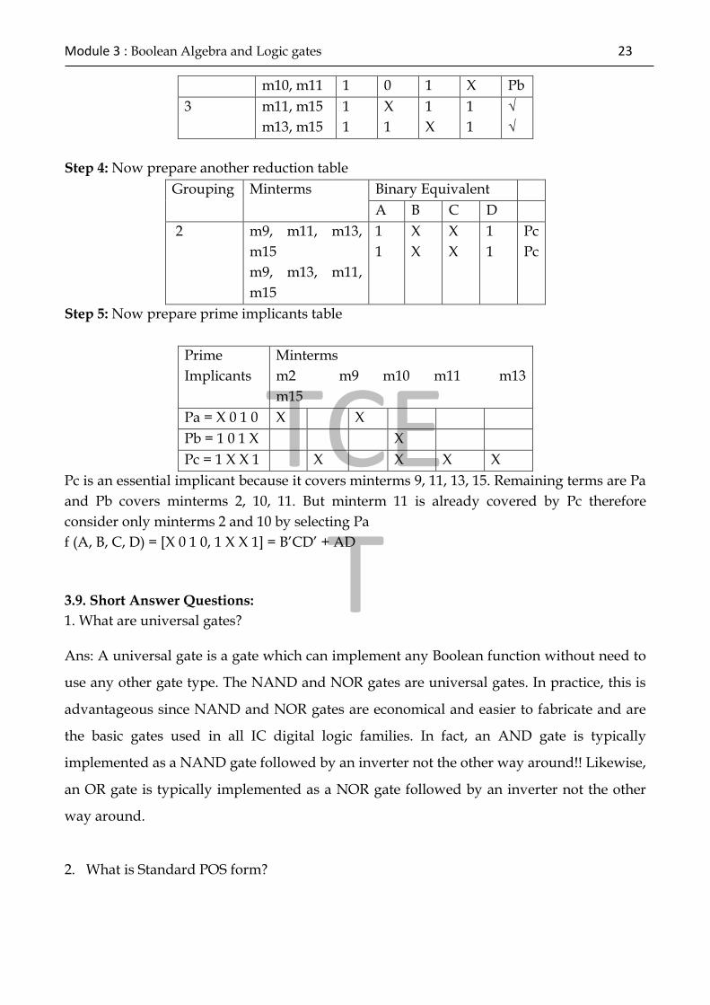
Step 4: Now prepare another reduction table
Grouping Minterms Binary Equivalent
A B C D
2 m9, m11, m13,
m15
m9, m13, m11,
m15
1
1
X
X
X
X
1
1
Pc
Pc
Step 5: Now prepare prime implicants table
Prime
Implicants
Minterms
m2 m9 m10 m11 m13
m15
Pa = X 0 1 0 X X
Pb = 1 0 1 X X
Pc = 1 X X 1 X X X X
Pc is an essential implicant because it covers minterms 9, 11, 13, 15. Remaining terms are Pa
and Pb covers minterms 2, 10, 11. But minterm 11 is already covered by Pc therefore
consider only minterms 2 and 10 by selecting Pa
f (A, B, C, D) = [X 0 1 0, 1 X X 1] = B’CD’ + AD
3.9. Short Answer Questions:
1. What are universal gates? Ans: A universal gate is a gate which can implement any Boolean function without need to
use any other gate type. The NAND and NOR gates are universal gates. In practice, this is
advantageous since NAND and NOR gates are economical and easier to fabricate and are
the basic gates used in all IC digital logic families. In fact, an AND gate is typically
implemented as a NAND gate followed by an inverter not the other way around!! Likewise,
an OR gate is typically implemented as a NOR gate followed by an inverter not the other
way around.
2. What is Standard POS form?
Ans: If each term in POS form contains all the literals then the POS form is known as
standard or canonical POS form.
3. What is Standard SOP form?
Ans: If each term in SOP form contains all the literals then the SOP form is known as
standard or canonical SOP form.
4. What is Two-level realization?
Ans: Realization of logic functions in which signals pass through two gates, such as AND-
OR, OR-AND,NAND-NAND,NOR-NOR realization.
5.What is combinational logic?
Ans: The logic in which the output at any instant of time is dependent only on the inputs
presents at that time
6.What is don’t care condition?
Ans. A minterm /maxterm in a logic function which may or may not be included.
3.8.2 Subjective Type Questions:
1) Simplify the following :A+ B+ C+ D Ans. A+B+C+D
2) Simplify the following: A [B+C ( )]. Ans. AB
3) Prove the following: BC+A C+AB +ABC=AB+BC+AC 4) Prove the following:
A B = A = B 5) State and prove DeMorgan’s theorem. 6) Simplify the following:
AB+ABC+A(B+A ) Ans.0 7) Prove the following using DeMorgan’s theorem AB+CD = AB . CD 8) State and prove the DeMorgan’s theorem 9) Simplify following expression using K-map and realize using AND-OR realization f(A,B,C,D)= ∑m(1,3,7,8,10,12,13,15)
10) Obtain K-map for f=A B+A C + C +A D + ABC + A B C a) Express it in standard SOP form. b) Minimize it and realize the minimized expression using NAND gates only
3.9 References:
1.R. P. Jain, “Modern Digital Electronics”, Tata McGraw Hill.
2. M. Morris Mano, “Digital Logic and computer Design”, PHI.

TCET
Module 3 : Boolean Algebra and Logic gates 25
3. Anil K. Maini, “Digital Electronics Principles and Integrated Circuits”, Wiley
India
Self-evaluation
Name of
Student
Class SE
Roll No.
Subject Logic Design
Module No. 03
S.No Tick
Your choice
1. Do you understand standard SOP & POS forms of
boolean expression & their reduction ?
o Yes
o No
2. Do you understand the different types reduction
methods ?
o Yes
o No
3. Do you understand basic digital circuits ? o Yes
o No
4. Do you understand boolean algebra and theorems?
o Yes
o No
5. Do you understand module ?
Yes, Completely.
Partialy.
No, Not at all.