Booklet “controls”– part A Quality of sprayed les---A-v... · PDF...
41
Version 2013 Booklet “controls”– part A Quality of sprayed concrete Technical Committee Asquapro
-
Upload
truongnguyet -
Category
Documents
-
view
222 -
download
0
Transcript of Booklet “controls”– part A Quality of sprayed les---A-v... · PDF...

Version 201 3
Booklet
“controls”– part A
Quality of sprayed concrete
Technical Committee Asquapro

ASQUAPRO Technical Committee
Booklet « Controls » - part A page 2 version updated in 2013
Quality of sprayed concrete
Booklet “Controls” – Part A

ASQUAPRO Technical Committee
Booklet « Controls » - part A page 3 version updated in 2013
TABLE OF CONTENTSTABLE OF CONTENTSTABLE OF CONTENTSTABLE OF CONTENTS
FOREWORD ................................................................................................... 5
INTRODUCTION ............................................................................................ 6
REFERENCE DOCUMENTS ............................................................................ 6
DOCUMENTS SPECIFIC TO SPRAYED CONCRETE ....................................... 6
AFNOR STANDARDS .................................... ...........................................................................................................6
STANDARDISED TESTS (NF EN & EN) ........................... ........................................................................................7
STANDARDS CONCERNING THE CONCRETE USABLE FOR PROJECTION ......................... 8
EUROPEAN STANDARDS APPROVED BY AFNOR (NF EN) ................. ................................................................8
NON “NF EN” STANDARDISED TESTS USABLE FOR SPRAYED CONCRETE ...... .............................................9
1 CONTROL ISSUES OF SPRAYED CONCRETE ............................................... 10
1.1 CHARACTERISTICS OF IMPLEMENTATION BY PROJECTION ................................. 10
1.1.1 MODIFICATION OF CONCRETE COMPOSITION ...............................................................................10
1.1.2 THICKNESS OF THE SPRAYED LAYER ............................. ...............................................................10
1.1.3 PRESENCE OF FRAMEWORKS .................................. .......................................................................10
1.1.4 PRESENCE OF FIBRES.......................................................................................................................10
1.2 HISTORY OF CONTROL ................................................................................................ 11
1.3 ENCOUNTERED PROBLEMS .......................................... ............................................ 12
1.3.1 FOR THE TWO PROJECTION METHODS ..........................................................................................12
1.3.1.1 Difference in composition before and after projection ....................................................... 12
1.3.1.2 Thin or reinforced layer ..................................................................................................... 12
1.3.1.3 Frameworks coating .......................................................................................................... 12
1.3.2 CHARACTERISTICS OF dry process ....................... ..........................................................................13
1.3.3 SPECIFIC PROBLEMS of PROJECTION BY WET PROCESS WITH DENSE FLOW ... ....................14
1.3.3.1 For fresh concrete ............................................................................................................. 14
1.3.3.2 For hardened concrete ...................................................................................................... 14
1.3.4 SPECIFIC PROBLEMS OF PROJECTION BY WET PROCESS WITH DILUTED FLOW ..................15
1.3.5 SPECIFIC PROBLEMS OF fIBRE REINFORCED CONCRETES ............. ..........................................15
1.3.5.1 Fibre content after projection............................................................................................. 15
1.3.5.2 Tests on hardened concrete ............................................................................................. 15
2 DESCRIPTION OF THE TESTS ............................................................... 16
2.1 PRESENTATION ........................................................................................................... 16
2.2 TEST OF COMPRESSIVE STRENGTH NF P 95-102 .................................................... 16
2.2.1 EXTRACT OF STANDARD NF P 95-102 ....................... ......................................................................16
2.2.2 COMMENTS ON THE TEST .................................................................................................................17
2.3 STANDARDISED TESTS SPECIFIC TO SPRAYED CONCRETE ................................. 18
2.3.1 NF EN 14488-1: FRESH AND HARDENED CONCRETE SAMPLING ........ ........................................18
2.3.2 NF EN 14488-2: COMPRESSIVE STRENGTH TESTS AT YOUNG AGE ......... ..................................19
2.3.2.1 Why such tests? ................................................................................................................ 19
2.3.2.2 Principle of the tests on young concrete ........................................................................... 20
2.3.2.2.1 Driving-in of a needle (test A) ..................................................................................................20
2.3.2.2.2 Driving in and wrenching of a threaded nail (test B) ................................................................20
2.3.3 NF EN 14488-3 FIBRE REINFORCED SPRAYED CONCRETE - BENDING TEST O N PRISM .........21
2.3.3.1 Why such a test? ............................................................................................................... 21
2.3.3.2 Test principle ..................................................................................................................... 22
2.3.4 NF EN 14488-4 TESTING SPRAYED CONCRETE: BOND STRENGTH BY DIRECT TENSION .......23
2.3.4.1 Why such a test? ............................................................................................................... 23
2.3.4.2 Test principle ..................................................................................................................... 24
2.3.5 NF EN 14488-5 - ENERGY ABSORBING CAPABILITY OF A FIBRE REIN FORCED SLAB .............25
2.3.5.1 Why such a test? ............................................................................................................... 25
ASQUAPRO Technical Committee
Booklet « Controls » - part A page 4 version updated in 2013
2.3.5.2 Test principle ...................................................................................................................... 25
2.3.5.3 Figure 1 of the standard ..................................................................................................... 26
Figures 2 and 3 of the standard ........................................................................................................... 26
2.3.6 NF EN 14488-6 MEASURE OF THE CONCRETE THICKNESS ON A SUPPORT ... ...........................27
2.3.6.1 Comment ........................................................................................................................... 27
2.3.7 NF EN 14488-7 FIBRE CONTENT OF FIBRE REINFORCED SPRAYED CON CRETE ....................27
2.3.7.1 Why such a test? ............................................................................................................... 27
2.3.7.2 Test principle ..................................................................................................................... 28
2.3.7.2.1 Method A (on hardened concrete) ...........................................................................................28
2.3.7.2.2 Method B (on fresh concrete) ..................................................................................................28
2.4 STANDARDISED TESTS NONSPECIFIC TO SPRAYED CONCRETE .......................... 29
2.4.1 TESTS ON FRESH CONCRETE ..........................................................................................................29
2.4.1.1 Tests before projection ............................................................................................................29
2.4.1.1.1 Dry process .............................................................................................................................29
2.4.1.1.2 Wet process with dense flow ...................................................................................................30
Measurement of water content .........................................................................................................30
Measurement of density ..................................................................................................................30
Measurement of subsidence ............................................................................................................30
Slump-flow test with Abrams cone ....................................................................................................31
Use of the LCPC workabilitymeter ....................................................................................................31
Measurement of entrained air content ...............................................................................................31
2.4.1.1.3 Wet process with diluted flow ..................................................................................................32
2.4.1.2 Tests on fresh concrete after projection ............................................................................ 32
2.4.2. TESTS ON HARDENED CONCRETE .................................................................................................32
2.5 NON-STANDARDISED TESTS USABLE FOR SPRAYED CONCRETE ......................... 33
2.5.1 TESTS ON FRESH CONCRETE SPECIFIC TO SPRAYED CONCRETE ............................................33
2.5.1.1 Measurement of density after projection ............................................................................ 33
2.5.1.1.1 Dry process .............................................................................................................................33
2.5.1.1.2 Wet process ............................................................................................................................34
2.5.1.2 Measurement of consistency............................................................................................. 34
2.5.1.2.1 Dry process .............................................................................................................................34
2.5.1.2.2 Wet process ............................................................................................................................35
2.5.2 TESTS ON FRESH CONCRETE NONSPECIFIC TO SPRAYED CONCRETE ....................................36
2.5.2.1 Measurement of fresh concrete consistency ...................................................................... 36
2.5.2.1.1 Test using a “plate plasticimeter” ............................................................................................36
2.5.2.1.2 Test using a “Pompabilimeter” ................................................................................................37
2.5.2.1.3 Other tests ...............................................................................................................................38
2.5.3 TESTS ON HARDENED CONCRETE NONSPECIFIC TO SPRAYED CONCRETE ....... .....................38
2.5.3.1 Non-destructive tests on building site ................................................................................. 38
2.5.3.1.1 Sonic echo-sounding with a hammer ......................................................................................38
2.5.4 TESTS ON HARDENED CONCRETE SPECIFIC TO SPRAYED CONCRETE .......... ..........................39
2.5.4.1 Strength at young ages .................................................................................................... 39
2.5.4.1.1 G.I.R. Procedure (Guaranteed Initial Resistance) ...................................................................39
3. MINIMUM FREQUENCIES OF CONTROLS ............................................. 40
3.1 CATEGORIES OF INSPECTION ................................................................................... 40
3.1.1 TABLE A1 ........................................... ..................................................................................................40
3.1.2 TABLE A2 ........................................... ..................................................................................................41
3.1.3 TABLE A3 ........................................... ..................................................................................................41
3.1.4 TABLE A4 ........................................... ..................................................................................................41

ASQUAPRO Technical Committee
Booklet « Controls » - part A page 5 version updated in 2013
FOREWORD
As the nine European standards concerning sprayed concrete were NF EN approved by the AFNOR at the end of 2006, this booklet - which was started at the beginning of the 2000s - was entirely reviewed in 2007. As there were a great number of tests to be described, studied and commented on, it was decided at that time to divide the booklet “Controls” into two parts:
•••• Part A: Controls, description and principles of the testing methods
•••• Part B:
Realisation on site and exploitation of the control tests, advices to choose the tests.
The present document is the new updated version of the booklet “Controls”- Part A. This version of 2013 has the same general plan of that of 2007 but includes some modifications due in particular to new standards concerning self-placing concretes that can be used for the control of sprayed concrete by wet process . The pages of the reference documents thus were modified and improved thanks to Daniel Poineau, consultant and writer member of the steering committee of the STRRES’s guides. He wrote an exhaustive list of the current standards that can be used for the controls of concretes. For the ASQUAPRO technical guide, only the standards concerning the internal and external control tests of sprayed concretes , quoted in this booklet A, were listed. In addition, other modifications concerning the tests were made in the 2013 version of booklet A compared to its 2007 version. For example the NF EN 12350-5 flow table test – rarely used in laboratories and never on building sites - was removed and replaced by test NF EN 12350-8: Abrams cone slumping, which is very easy to carry out on building sites.
ASQUAPRO Technical Committee
Booklet « Controls » - part A page 6 version updated in 2013
INTRODUCTION
The implementation process of sprayed concrete being its main characteristic, the testing methods to control its quality are more or less the same as those used for poured concretes. For a very long time, controls were limited to the inspection of materials and equipments used, to the respect of the composition prescribed for the mixture, to the examination of the surface aspect after projection, to the measure of the sprayed thickness and to the control of the adhesion by hammer testing. Currently, thanks to various tests, it is possible to check some characteristics of freshly-sprayed concrete and the performances of hardened concrete before, during and after works. The tests are divided into: � Internal audits carried out by the company according to the methods and frequencies
described in its Quality Assurance Plan.
� External audits carried out either by an entity of the company, separate from the works, or by an external organisation paid by the company.
� External audits carried out by an independent organisation paid by the contractor.
REFERENCE DOCUMENTS
This booklet refers to applicable standards or recommendations. For dated references, only the dated edition applies. For undated references it is the last known edition which is taken into account. DOCUMENTS SPECIFIC TO SPRAYED CONCRETE
AFNOR STANDARDSAFNOR STANDARDSAFNOR STANDARDSAFNOR STANDARDS
NF P 95-102 April 2002 Civil engineering works Repair and reinforcement of concrete and masonry-sp rayed concrete structures - Specifications relating to the technique and materi als used
This standard is not in contradiction with NF EN standards hereafter and it gives very useful information on the
grading curves of the mixtures which do not appear in the NF EN 14487-1.Thus it is still used.

ASQUAPRO Technical Committee
Booklet « Controls » - part A page 7 version updated in 2013
STANDARDISEDSTANDARDISEDSTANDARDISEDSTANDARDISED TESTS (NF EN & EN)TESTS (NF EN & EN)TESTS (NF EN & EN)TESTS (NF EN & EN)
NF EN 14487-1 March 2006 Sprayed concrete
Part 1: definitions, specifications and conformity NF EN 14487-2 April 2006 Sprayed concrete
Part 2: Execution NF EN 14488-1 October 2005 Tests for sprayed concrete
Part 1 sampling fresh and hardened concrete
NF EN 14488-2 October 2006 Tests for sprayed concrete
Part 2: compressive strength of young sprayed concrete
NF EN 14488-3 July 2006 Tests for sprayed concrete
Part 3: flexural strengths (first peak, ultimate and residual)
of fibre reinforced beam specimens NF EN 14488-4 October 2005 Tests for sprayed concrete
Part 4: Bond strength of cores by direct tension NF EN 14488-5 July 2006 Tests for sprayed concrete
Part 5: determination of energy absorption capacity of fibre
reinforced slab specimens
NF EN 14488-6 June 2006 Tests for sprayed concrete
Part 6: thickness of concrete on a substrate
NF EN 14488-7 July 2006 Tests for sprayed concrete
Part 7: fibre content of fibre reinforced concrete
NF EN 934-1 April 2008 Admixtures for concrete, mortar and grout
Part 1: common requirements
NF EN 934-5 December 2007 Admixtures for concrete, mortar and grout
Part 5: admixtures for sprayed concrete: definitions,
requirements, conformity, marking and labelling

ASQUAPRO Technical Committee
Booklet « Controls » - part A page 8 version updated in 2013
AFTES recommendations
AFTES 1979: Tunnels construction method - Immediate support using sprayed concrete and bolting
TOS n°31
AFTES 1993: Technology and implementation of sprayed concrete - TOS n°117
AFTES 1994: Technology and implementation of fibre reinforced sprayed concrete - TOS n°126
AFTES 2001: Design and dimensioning of sprayed concrete for underground works - TOS n°164
STANDARDS CONCERNINGSTANDARDS CONCERNINGSTANDARDS CONCERNINGSTANDARDS CONCERNING CONCRETE USABLE FOR CONCRETE USABLE FOR CONCRETE USABLE FOR CONCRETE USABLE FOR PROJECTIONPROJECTIONPROJECTIONPROJECTION
EUROPEAN STANDARDS AEUROPEAN STANDARDS AEUROPEAN STANDARDS AEUROPEAN STANDARDS APPROVED BY AFNOR (NFPPROVED BY AFNOR (NFPPROVED BY AFNOR (NFPPROVED BY AFNOR (NF EN)EN)EN)EN)
NF EN 206–1 April 2004 Concrete Part 1: Specification, performance, production and conformity
NF EN 206–1/A1 April 2005 Concrete Part 1: Specification, performance, production and conformity
(Amendment 1 to standard NF EN 206-1)
NF EN 206–1/A2 October 2005 Concrete Part 1:
Specification, performance, production and conformity
(Amendment 2 to standard NF EN 206-1)
NF EN 206–1/CN December 2012 Concrete Part 1: Specification, performance, production and conformity
(National addition to standard NF EN 206-1)
NF EN 12350-1 Testing fresh concrete Part 1 Sampling April 2012
NF EN 12350-2 Testing fresh concrete Part 2 Slump test April 2012
NF EN 12350-6 Testing fresh concrete Part 6 Dens ity April 2012
NF EN 12350-7 Testing fresh concrete Part 7 Air content
compression methods April 2012 NF EN 12350-8 Testing fresh concrete Part 8 Slump- flow test November 2010
NF EN 12350-9 Testing fresh concrete Part 9 V-funne l test November 2010
NF EN 12390-5 Testing hardened concrete Part 5 Fle xural strength of test specimens April 2012
NF EN 12390-7 Testing hardened concrete Part 7 Density September 2001 NF EN 12390-8 Testing hardened concrete Part 8 Dept h of penetration of water under pressure April 2012
NF EN 14889-1 Steel fibres – Part 1: steel fibres
Definitions, specifications and conformity November 2006
NF EN 14889-2 Fibres for concrete – Part 2: polymer fibres
Definitions, specifications and conformity November 2006
NF EN 12504-1 Testing concrete in structures - Part 1: core specimens
Taking, examining and testing in compression April 2012

ASQUAPRO Technical Committee
Booklet « Controls » - part A page 9 version updated in 2013
NONONONONNNN “NF EN” STANDARDI“NF EN” STANDARDI“NF EN” STANDARDI“NF EN” STANDARDISSSSEDEDEDED TESTS TESTS TESTS TESTS USABLE FOR SPRAYED CUSABLE FOR SPRAYED CUSABLE FOR SPRAYED CUSABLE FOR SPRAYED CONCRETEONCRETEONCRETEONCRETE
Measure of water content of fresh concrete after projection Measure of cement and fines content of fresh concrete after projection Measure of fresh concrete consistency after projection (dry process) with a penetrometer Measuring the flow time using a workability meter (wet process) NF P 18-452 Estimating fresh concrete consistency using the appropriate tool (wet process) Sonic survey with hammer on hardened concrete to control adhesion to the support

ASQUAPRO Technical Committee
Booklet « Controls » - part A page 10 version updated in 2013
1 CONTROL ISSUES OF SPRAYED CONCRETE
1.11.11.11.1 CHARACTERISTICS CHARACTERISTICS CHARACTERISTICS CHARACTERISTICS OF OF OF OF IMPLEMENTATION BY PRIMPLEMENTATION BY PRIMPLEMENTATION BY PRIMPLEMENTATION BY PROJECTIONOJECTIONOJECTIONOJECTION
1.1.11.1.11.1.11.1.1 MODIFICATION OF CONCMODIFICATION OF CONCMODIFICATION OF CONCMODIFICATION OF CONCRETE COMPOSITION RETE COMPOSITION RETE COMPOSITION RETE COMPOSITION
Because of the loss of aggregates by rebound, the projection increases the cement content of the concrete in place and consequently its resistance, in particular when it is made by dry process. When an accelerating admixture is introduced into the projection jet, it also modifies the composition and performances of concrete. The composition of the concrete in place being different from that of the mixture introduced into the machine, it is essential to manufacture or to take the tests samples directly from sprayed concrete because the fabrication of samples or concrete test-tubes poured in moulds would not be representative.
1.1.21.1.21.1.21.1.2 THICKNESS OF THE SPRTHICKNESS OF THE SPRTHICKNESS OF THE SPRTHICKNESS OF THE SPRAYED LAYERAYED LAYERAYED LAYERAYED LAYER
For many applications of sprayed concrete (for example structures repairs or repointings), the implemented layer does not have a sufficient thickness to take off cylindrical test-tubes for crushing tests.
1.1.31.1.31.1.31.1.3 PRESENCE OF FRAMEWORPRESENCE OF FRAMEWORPRESENCE OF FRAMEWORPRESENCE OF FRAMEWORKSKSKSKS
When the sprayed concrete layer is thick, for example for supports, the concrete is generally reinforced by one or more reinforcement layers. The free from steels in situ corings are relatively difficult to realise and there is a risk to cut the frameworks.
1.1.41.1.41.1.41.1.4 PRESENCE OF FIBRESPRESENCE OF FIBRESPRESENCE OF FIBRESPRESENCE OF FIBRES
Concrete always being sprayed towards a wall (structure, formwork, rock…), the positioning of the fibres (whatever their nature) in the sprayed concrete is not completely random. The fibres indeed tend to go in successive plans, parallel to the wall but in a random way in each one of these plans. This ‘semi random’ positioning is an advantage or a disadvantage depending on the direction of the principal load in this element, particularly as regards the tensile or bending strength of an element of the structure. This characteristic must be taken into account to prescribe controls.
ASQUAPRO Technical Committee
Booklet « Controls » - part A page 11 version updated in 2013
1.21.21.21.2 HISHISHISHISTORTORTORTORY OF CONTROLY OF CONTROLY OF CONTROLY OF CONTROL
For a very long time, the only controls done were the conformity with the regulations of the mix composition and the inspection of the surface aspect after projection. In the United States and then in some European countries, because of the characteristics of projection (see 1.1), test-tubes cored or sawn from samples sprayed in boxes have been used. Around 1960 in France, the first contractor who applied this testing method was EDF for the construction of tunnels intended for hydroelectric installations in the Alps. After EDF, the railroads, the subways, the motorway companies and private contractors did the same. On its “Rhone-Alps” building sites, in addition to the simple crushing tests, EDF: • has analysed the sprayed mixture's grain size
• has studied the influence of accelerating admixtures on strengths,
• has created a data bank which was then used by the AFTES for the writing of the first
recommendations on the implementation of sprayed concrete (recommendations published in 1972 in the review “Tunnels & Underground Works”, n°1).
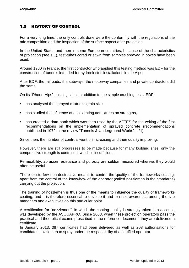
Since then, the number of controls went on increasing and their quality improving. However, there are still progresses to be made because for many building sites, only the compressive strength is controlled, which is insufficient. Permeability, abrasion resistance and porosity are seldom measured whereas they would often be useful. There exists few non-destructive means to control the quality of the frameworks coating, apart from the control of the know-how of the operator (called nozzleman in the standards) carrying out the projection. The training of nozzlemen is thus one of the means to influence the quality of frameworks coating, and it is therefore essential to develop it and to raise awareness among the site managers and executives on this particular point. A certification for “nozzlemen”, in which the coating quality is strongly taken into account, was developed by the ASQUAPRO. Since 2003, when these projection operators pass the practical and theoretical exams prescribed in the reference document, they are delivered a certificate. In January 2013, 387 certificates had been delivered as well as 208 authorisations for candidates nozzlemen to spray under the responsibility of a certified operator.
ASQUAPRO Technical Committee
Booklet « Controls » - part A page 12 version updated in 2013
1.31.31.31.3 ENCOUNTERED PROBLEMSENCOUNTERED PROBLEMSENCOUNTERED PROBLEMSENCOUNTERED PROBLEMS
1.3.11.3.11.3.11.3.1 FOR THE TWO PROJECTIFOR THE TWO PROJECTIFOR THE TWO PROJECTIFOR THE TWO PROJECTION METHODSON METHODSON METHODSON METHODS
1.3.1.1 Difference in composition before and after projection
This difference comes from the fact that the implementation by projection always has an influence on the compactness of in situ concrete. Therefore, the concrete of the control test sample must be sprayed (the only exception is that of the tests on fresh concrete used to control the consistency of a concrete to be sprayed by wet process). The concrete test-tubes for the tests on hardened concrete must thus be taken either by extraction of core samples in the structure or by sawing or extraction of core samples from sprayed slabs.
1.3.1.2 Thin or reinforced layer
The sprayed layers being generally thin, their thickness is very seldom sufficient to allow the extraction of core samples with a slenderness ratio of 2, the ones that are usually used in France to measure the resistance of hardened concrete.
When the concrete thickness exceeds 15 cm and that it is little reinforced, it is obviously possible to take Ø 6 cm and 12 cm long core samples, after having located the steels to avoid cutting them. In the other cases, the universally adopted solution - which solves the two stated problems - consists in making the samples by projection in boxes or trays so as to create slabs of sufficient size to allow the extraction of core samples. In France, the sprayed concrete slab which is described in standard NF P 95-102 must be 15 cm thick in the central part where the core samples are extracted from. The dimensions prescribed by the 2006 standard NF EN 14487-1 being compatible with those of the “AFNOR box” in NF P 95-102, this type of box, well-known for the companies, can thus still be used.
1.3.1.3 Frameworks coating
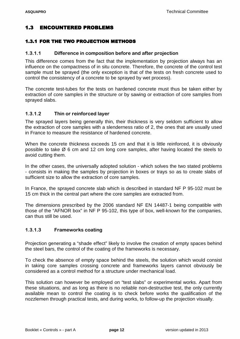
Projection generating a “shade effect” likely to involve the creation of empty spaces behind the steel bars, the control of the coating of the frameworks is necessary. To check the absence of empty space behind the steels, the solution which would consist in taking core samples crossing concrete and frameworks layers cannot obviously be considered as a control method for a structure under mechanical load. This solution can however be employed on “test slabs” or experimental works. Apart from these situations, and as long as there is no reliable non-destructive test, the only currently available mean to control the coating is to check before works the qualification of the nozzlemen through practical tests, and during works, to follow-up the projection visually.
ASQUAPRO Technical Committee
Booklet « Controls » - part A page 13 version updated in 2013
1.31.31.31.3.2.2.2.2 CHARACTERISTICS OF DCHARACTERISTICS OF DCHARACTERISTICS OF DCHARACTERISTICS OF DRY PROCESSRY PROCESSRY PROCESSRY PROCESS
In situ concrete sprayed by dry process has a different composition from that of the mixture introduced into the machine. This distinctive feature is generated by the fact that the losses caused by projection affect definitely more the large elements (fine gravels and sand coarse grains) than cement and other fine products (filler, sand fine particles, silica fume, fly-ash), as well as powder additives. It results from it that, for the concrete in place, the cement content is considerably higher than that of the basic mixture, which obviously increases its compressive strength. The cement enrichment can vary from 20% to sometimes more than 100%, depending on:
•••• the thickness of the layer, •••• the nature of the substrate,
•••• the formulation of the basic mixture,
•••• the nature of aggregates,
•••• the use of additions and additives,
•••• the dampening,
•••• the projection distance,
•••• the jet speed,
•••• the handling of the nozzle by the operator. An analysis of the freshly-sprayed concrete allows to measure this enrichment. Obviously, it can only be made on sampling carried out in situ immediately after projection (very difficult operation when an accelerating admixture is used). This analysis of the concrete obliges to measure simultaneously on the one hand the water content and on the other hand the content of cement+fines on the in situ sampling. These measures are made in France since a couple of decades, in particular on large repair works. Unfortunately they are difficult to carry out. For this reason, the European standard experts decided not to standardise them as testing methods. In consequence, the standard does not formulate any requirement relating to the water/cement ratio in the concrete in place. Another characteristic of projection by dry process relates to the measure of the freshly sprayed concrete consistency. Indeed, the testing methods employed for poured concretes (slump test, Vebe test, spreading…) are obviously inappropriate. To evaluate the consistency of the concrete in place without altering it by an extraction, a pocket penetrometer can give a “consistency index”. This test is very simple; however, it was not standardised in France nor in Europe.
ASQUAPRO Technical Committee
Booklet « Controls » - part A page 14 version updated in 2013
1.3.31.3.31.3.31.3.3 SPECIFIC SPECIFIC SPECIFIC SPECIFIC PROBLEMS PROBLEMS PROBLEMS PROBLEMS OF OF OF OF PROJECTION BY PROJECTION BY PROJECTION BY PROJECTION BY WETWETWETWET PROCESS WITHPROCESS WITHPROCESS WITHPROCESS WITH
DENSE FLOWDENSE FLOWDENSE FLOWDENSE FLOW
1.3.3.1 For fresh concrete
With projection by wet process with dense flow, the increase of the cement content mentioned for the dry process can be regarded as negligible. The water content of in situ concrete is also very close to that of freshly mixed concrete. Taking into account these small differences, the consistency of fresh sprayed concrete can be evaluated, by the standardised slump test for example, either on a sampling made at the time of delivery on the site, or on a sprayed sample … In the case of a sampling after projection, the test is not carried out on a concrete with the same consistency as the concrete in place, because of the difference of compaction between the sprayed sample and the one compacted manually in the slump test. For this reason and because its use is very limited, it is not recommended. Nonetheless, the tests before projection are very useful because they allow to control that the delivered basic mixture has the required consistency grade. In consequence, they are the ones generally prescribed.
1.3.3.2 For hardened concrete
The French standard NF P 95-102 of April 2002 recommends that the slope of the box used for the production of the sprayed control slabs should not be higher than 20° from the vertical line. This recommendation can be easily respected in the dry process even with a concrete without accelerator, but in the wet process the maximum authorised slope can be respected only when a setting accelerator is added at the nozzle, which is generally the case for concretes sprayed in tunnels or on vertical excavation walls. In the other cases, for example for a projection on little inclined banks or for “very sticky” sand concretes generally sprayed in 4 to 6 cm thick layers, setting accelerators are hardly ever used. The filling by projection of a very fluid concrete of a 15cm thick control box installed with a maximum slope of 20° becomes impossible then. For these sprayed concretes by wet process and without accelerators, the projection in a horizontal box cannot be avoided.

ASQUAPRO Technical Committee
Booklet « Controls » - part A page 15 version updated in 2013
1.3.41.3.41.3.41.3.4 SPECIFIC PROBLEMS OFSPECIFIC PROBLEMS OFSPECIFIC PROBLEMS OFSPECIFIC PROBLEMS OF PROJECTION BY WET PRPROJECTION BY WET PRPROJECTION BY WET PRPROJECTION BY WET PROCESS WITH OCESS WITH OCESS WITH OCESS WITH
DILUTED FLOWDILUTED FLOWDILUTED FLOWDILUTED FLOW
Because of the high speed transport in an air flow and of the resulting losses, an increase of the cement content occurs just like in the dry process but it is definitely less important. Transport by diluted flow has another consequence: On the way between the machine and the nozzle, the mixture dries out. The reduction of the water content which results from it can lead to a 50% reduction of the slump for example. Any measure of in situ consistency, if it were prescribed, would thus have to be made on a sprayed sample in spite of the difference in compaction announced in paragraph 1.3.3.1 about projection with dense flow. This test is less necessary than in dense flow because the reduction of the water content and the increase of the cement content have beneficial effects on the resistance of the concrete in place. Only the tests on fresh concrete before projection are necessary as part of the control of works because they allow to check the conformity of the delivered concrete with the prescribed consistency grade.
1.3.51.3.51.3.51.3.5 SPECIFIC PROBLEMS OFSPECIFIC PROBLEMS OFSPECIFIC PROBLEMS OFSPECIFIC PROBLEMS OF FIBRE REINFORCED CONFIBRE REINFORCED CONFIBRE REINFORCED CONFIBRE REINFORCED CONCRETESCRETESCRETESCRETES
1.3.5.1 Fibre content after projection
The fibre content can be modified by projection and in some extreme circumstances, this modification can even lead to an absence of fibres in the concrete in place. It is therefore essential to measure this content in the concrete when it is freshly sprayed; no need to wait the results of the tests on hardened concrete that would show that the performances are not in conformity with the requirements in spite of a suitable fibre proportioning in the basic mixture. This is more or less easy depending on the type of fibres used.
1.3.5.2 Tests on hardened concrete
As we have just seen, the in situ fibre content can be very different from that of the basic mixture; In consequence, the tests on hardened fibre reinforced sprayed concretes, when they are prescribed, must be done on test-tubes taken off or made by projection. For the compressive or tensile strengths tests of fibreless concretes, the extractions of core samples are almost always carried out in the same direction as projection (in samples sprayed in boxes or in situ). In the particular case of fibre reinforced sprayed concretes, the extractions of core samples carried out in a direction perpendicular to that of projection are sometimes prescribed to study the influence of the fibres orientation. For the bending test centred on a slab, now called the energy absorption test, the samples are sprayed in square boxes (60 x 60 x 10 cm) and for the bending tests on prisms, the test-tubes are sawn out from sprayed slabs.

ASQUAPRO Technical Committee
Booklet « Controls » - part A page 16 version updated in 2013
2 DESCRIPTION OF THE TESTS
2.12.12.12.1 PRESENTATIONPRESENTATIONPRESENTATIONPRESENTATION
This booklet briefly describes the testing methods, standardised or not, specific to sprayed concrete or not, that can be used to control the quality of sprayed concrete. The application of these testing methods concerning operations to be realised on building sites are the subject of the booklet “Controls” part B. The test of standard NF P 95-102 approved in April 2002 will be first examined. The first version of this standard, approved in June 1992, was modified in 2002 in order not to contradict the European standards EN 14487 and EN 14488 in the process of validation at that time. The test prescribed in this French standard to measure the compressive strength of a sprayed concrete being more demanding than that of EN 14487-1 (for example minimal diameter of samples: 60 mm instead of 50 mm for EN), the regulations of the NF P 95-102 of 2002 can still be respected in France.
2.22.22.22.2 TEST TEST TEST TEST OF OF OF OF COMPRESSIVE STRENGTHCOMPRESSIVE STRENGTHCOMPRESSIVE STRENGTHCOMPRESSIVE STRENGTH NF P 95NF P 95NF P 95NF P 95----102102102102
For this test the standard lists the instructions regarding the making of the samples. It defines the dimensions of the box and the conditions of core sampling for samples intended for the tests on hardened concrete. As indicated above in paragraph 2.1, this test can continue to be used. In consequence, we give below the instructions taken from the standard of 2002.
2.2.12.2.12.2.12.2.1 EXTRACT OF STANDARD EXTRACT OF STANDARD EXTRACT OF STANDARD EXTRACT OF STANDARD NF P 95NF P 95NF P 95NF P 95----102102102102
Instructions related to the making of the samples and listed in paragraph 10.1.1.1 of the version of 2002.
“… concrete is sprayed in flat boxes and under conditions upstream of the nozzle rigorously identical to those
on site: machine, components, and methods.
The following boxes are used: they comprise a wooden bottom of a surface larger or equal to 0.25 m2 and of
width larger or equal to 0.40 m, the small side of the box being placed horizontally. The concrete is sprayed
perpendicular to the bottom of the box placed vertically or with a slope lower than 20° on the vertical. The
thickness of the concrete is 15 cm in the coring zone, so as to obtain by coring and sawing 12 cm high
samples.
The projection distance (d) * is in theory equal to 1 m except if the implementation conditions require a lower
distance.
* (d) is the distance indicated on the drawing of the standard

ASQUAPRO Technical Committee
Booklet « Controls » - part A page 17 version updated in 2013
2.2.22.2.22.2.22.2.2 COMMENTS ON THE TESTCOMMENTS ON THE TESTCOMMENTS ON THE TESTCOMMENTS ON THE TEST
The writers of the standard imagined a box small enough to be manually transportable but big enough to allow the coring of at least 6 samples of Ø 6 cm and 15 cm high, so as to obtain after sawing and surfacing, samples with a slenderness ratio of 2. Boxes made of plastic, polystyrene, sheet metal or another material can be used but, in this case, a wood plate must be placed on the bottom where the concrete will be sprayed. It should be noted that the recommended minimal surface (0.25 m2) is clearly insufficient when projection is carried out using a mechanical arm (called “robot”). In this case, at least twice this surface is necessary. The projection distance of 1 metre is given for information purposes. As it is indicated in the text, this distance must be reduced when the space on the building site is insufficient to allow projection (for example in a 1 metre wide gallery). Conversely, when large flow machines are used and that the distance nozzle-wall is definitely higher than 1 metre, the test must be carried out with the same projection distance as the one used on site. For projection by dry process , it is possible to reduce the “trapping” of the losses while also complying with the indications concerning the box. Indeed, as it is not stipulated in the standard that the sides of the box must be full, it is possible to perforate them using for example thickness markers made up of battens or rafters superimposed at their ends.
Box with open sides for manual projection
This device makes it possible for the losses to escape sideways during projection. This possibility was included in European standard NF EN 14488-1 (paragraph 4.3).

ASQUAPRO Technical Committee
Booklet « Controls » - part A page 18 version updated in 2013
As it was indicated in paragraph 1.3.3.2, in the case of a projection by wet process of concretes without accelerating admixture (for example for sand concretes very often used to spray thin shells in sewers) downward and almost vertical projection is impossible on a 15 cm layer. It is thus authorised to place the box horizontally but in this case, it is essential to use a box with closed sides.
The sprayed sample area the cores must be taken from was not defined in the text but it is indicated on figure 6 of standard NF P 95 102. The coring zone is a Ø 30 cm circle located at the centre of the slab (where the concrete must be 15 cm thick).
Boxes for projection by wet process with robotic ar m (Bois de Peu tunnel)
2.32.32.32.3 STANDARDISED TESTS SSTANDARDISED TESTS SSTANDARDISED TESTS SSTANDARDISED TESTS SPECIFIC TO SPRAYED CPECIFIC TO SPRAYED CPECIFIC TO SPRAYED CPECIFIC TO SPRAYED CONCRETEONCRETEONCRETEONCRETE
2.3.12.3.12.3.12.3.1 NF EN 14488NF EN 14488NF EN 14488NF EN 14488----1:1:1:1: FRESH AND HARDENED CFRESH AND HARDENED CFRESH AND HARDENED CFRESH AND HARDENED CONCRETE SAMPLINGONCRETE SAMPLINGONCRETE SAMPLINGONCRETE SAMPLING
This sampling which is described in part 1 of the standard EN 14488, directly relates to the AFNOR test quoted in paragraph 2.2.1 for which it was noticed that the dimensions of the box (0.25 m2 with small side ≥ 0.40 m) were complying with the regulations of the new standard and could thus be kept for manual projection. Nevertheless, there is a small difference between the NF P 95 102 and the NF EN 14488-1. The Ø 30 cm coring zone becomes a square with a side measure equal to the side of the box minus 2 times the height of the edges. You can see that with an AFNOR type box of 600 x 600 x 150, it remains the 300mm of the old coring zone, which is higher than the new requirement of a 250 mm x 250 mm square.
ASQUAPRO Technical Committee
Booklet « Controls » - part A page 19 version updated in 2013
“Suitable measures” must nevertheless be taken to avoid the trapping of losses in the edges of the box. By using openwork edges thanks to 3 alternate layers of 50 mm battens, or 2 layers of rafters as it is often currently done, it is possible to obtain a greater coring zone and to make for example 9 core specimens of Ø 60 mm instead of 6. Concerning the dimensions of the core specimens, the standard 14488-1 does not give any indication and it is necessary to consult the standard NF EN 14487-1 to find the regulations which are less demanding than the French ones (in theory Ø 60 mm with a slender ratio of 2) Indeed the table 8 of paragraph 5.5 of EN 14487-1 specifies that the core specimens are taken from slabs sprayed in accordance with EN 14488-1 and that their minimal diameter must be 50 mm and the ratio height/diameter must be equal to 1 or 2. The following note relates to the ratio length/diameter:
• “2.0 if the strength value must be compared with the strength of a cylinder” • “1.0 if the strength value must be compared with the strength of a cube”
Taking into account the number of tests carried out in France since 1972 on core specimens of Ø 60 mm with a slenderness ratio of 2 (in accordance with the first AFTES recommendations published at this date), it appears definitely preferable to keep these dimensions. The standard NF EN 14488-1 quotes the French regulations about the installation of the box at less than 20° from the vertical but does not take account of the impossible aspect of this requirement if a fluid concrete without accelerating admixture is sprayed by wet process. The problem still not being solved, the comment made in paragraph 1.3.3.2 of the present document remains valid. The exemption (horizontal box) must be mentioned on the tests report.
2.3.22.3.22.3.22.3.2 NF EN 14488NF EN 14488NF EN 14488NF EN 14488----2:2:2:2: COMPRESSIVE STRENGTHCOMPRESSIVE STRENGTHCOMPRESSIVE STRENGTHCOMPRESSIVE STRENGTH TESTS AT YOUNG AGETESTS AT YOUNG AGETESTS AT YOUNG AGETESTS AT YOUNG AGE
2.3.2.1 Why such tests?
The test described in the previous paragraph cannot be used to estimate the resistance of a sprayed concrete a few hours only after its implementation. It is indeed impossible to core in a sample whose compressive strength is lower than 10 MPa because the coring device unfixes the aggregates which start to turn into the insufficiently hardened mixture. When sprayed concrete is used as immediate support - in the construction of tunnels for example - the engineers always sought to determine the strength reached by concrete at young age. Since 1990, the SNCF in France has succeeded in sawing out cubes from slabs sprayed 3 hours before, and in measuring the compressive strength of special guaranteed initial resistance concretes.
ASQUAPRO Technical Committee
Booklet « Controls » - part A page 20 version updated in 2013
In Switzerland, the “pull out test” was used with the same aim by measuring the strength necessary to tear off an insert, and the pull-out cone. In Austria two successive tests were developed: the first by the driving in of a needle, the second by the driving in and pulling out of a threaded nail. The WG 10 working group of the TC 104 committee of the CEN used the Austrian studies and experiments to develop the standard 14488-2 entitled “Compressive strength of young sprayed concrete”.
2.3.2.2 Principle of the tests on young concrete
2.3.2.2.1 Driving-in of a needle (test A)
The test A measures the necessary strength to have a needle penetrate into young concrete whose resistance is supposed to be ranging between 0.2 and 1.2 MPa. The measure is taken using a penetrometer including a needle of Ø 3 mm with a conical point with an angle of 60°. The point of this needle must be inserted to a depth of 15 mm in the sprayed concrete. The value of the reaction force allows to give an estimate of the compressive strength from a conversion curve. The method makes it possible to evaluate this resistance in a range going from 0.2 to 1.2 MPa. It is envisaged to repeat the test 10 times as quickly as possible (and in less than one minute for resistances lower than 0.5 MPa).
2.3.2.2.2 Driving in and wrenching of a threaded na il (test B)
The test B uses the measurement of the force necessary to tear off a nail inserted beforehand in a concrete whose resistance is higher than the one of test A, which was generally practised on this same sprayed concrete when it was younger. The test B is considered applicable when the resistance is supposed to be ranging between 3 and 16 MPa. The nails are hammered using a stud gun and using the appropriate device to make it penetrate at least 20 mm. The convenient moment for the driving in of the nails must be based on the hardening of the material. The nails must have a Ø 3.7 mm, threaded ends allowing their connection to the extraction device and sufficient lengths to obtain the required penetration > 20 mm (the point of the sealing nails is ogival-shaped). If the longest nail penetrates completely, it is recommended to await and start again the test when the concrete is harder. If the protruding part of the nail is too long (penetration < 20 mm) a shorter nail must be used.
ASQUAPRO Technical Committee
Booklet « Controls » - part A page 21 version updated in 2013
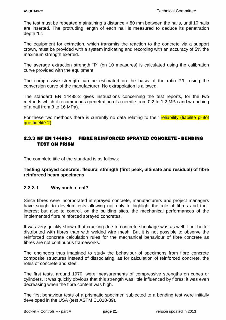
The test must be repeated maintaining a distance > 80 mm between the nails, until 10 nails are inserted. The protruding length of each nail is measured to deduce its penetration depth “L”. The equipment for extraction, which transmits the reaction to the concrete via a support crown, must be provided with a system indicating and recording with an accuracy of 5% the maximum strength exerted. The average extraction strength “P” (on 10 measures) is calculated using the calibration curve provided with the equipment. The compressive strength can be estimated on the basis of the ratio P/L, using the conversion curve of the manufacturer. No extrapolation is allowed. The standard EN 14488-2 gives instructions concerning the test reports, for the two methods which it recommends (penetration of a needle from 0.2 to 1.2 MPa and wrenching of a nail from 3 to 16 MPa). For these two methods there is currently no data relating to their reliability (fiabilité plutôt que fidélité ?).
2.3.32.3.32.3.32.3.3 NF EN 14488NF EN 14488NF EN 14488NF EN 14488----3333 FIBRE REINFORCED SPRFIBRE REINFORCED SPRFIBRE REINFORCED SPRFIBRE REINFORCED SPRAYED AYED AYED AYED CONCRETE CONCRETE CONCRETE CONCRETE ---- BENDING BENDING BENDING BENDING
TEST ON PRISMTEST ON PRISMTEST ON PRISMTEST ON PRISM
The complete title of the standard is as follows: Testing sprayed concrete: flexural strength (first peak, ultimate and residual) of fibre reinforced beam specimens
2.3.3.1 Why such a test?
Since fibres were incorporated in sprayed concrete, manufacturers and project managers have sought to develop tests allowing not only to highlight the role of fibres and their interest but also to control, on the building sites, the mechanical performances of the implemented fibre reinforced sprayed concretes. It was very quickly shown that cracking due to concrete shrinkage was as well if not better distributed with fibres than with welded wire mesh. But it is not possible to observe the reinforced concrete calculation rules for the mechanical behaviour of fibre concrete as fibres are not continuous frameworks. The engineers thus imagined to study the behaviour of specimens from fibre concrete composite structures instead of dissociating, as for calculation of reinforced concrete, the roles of concrete and steel. The first tests, around 1970, were measurements of compressive strengths on cubes or cylinders. It was quickly obvious that this strength was little influenced by fibres; it was even decreasing when the fibre content was high. The first behaviour tests of a prismatic specimen subjected to a bending test were initially developed in the USA (test ASTM C1018-89).
ASQUAPRO Technical Committee
Booklet « Controls » - part A page 22 version updated in 2013
For this test, the deformation is measured and the curve load/deformation is drawn. This curve shows a peak corresponding to the first failure but then the curve, instead of crashing down immediately as for a non-reinforced prism, can show other peaks and go down then more or less rapidly depending on the quality of the fibres and their proportioning. The ASTM test was used for a very long time in the whole world. An alternative was then developed in Japan: it exploited the curve load/deformation in a slightly different way. In France a “4 points bending test” at constant speed on specimens of 140 x 140 x 500 was developed for poured fibre reinforced concretes. It could be used for sprayed concrete provided that prisms were sawn out of a sprayed slab. This AFNOR XP-P 18409 test is now canceled. And finally, in Sweden a test was developed especially intended for fibre reinforced sprayed concrete. This test is similar to the French test even for the dimensions of the specimen but it includes an evaluation of ductility by examination of three successive residual strengths. The WG 10 working group of the committee TC 104 of the CEN used the Swedish studies and experiments to develop the standard NF EN 14488-3.
2.3.3.2 Test principle
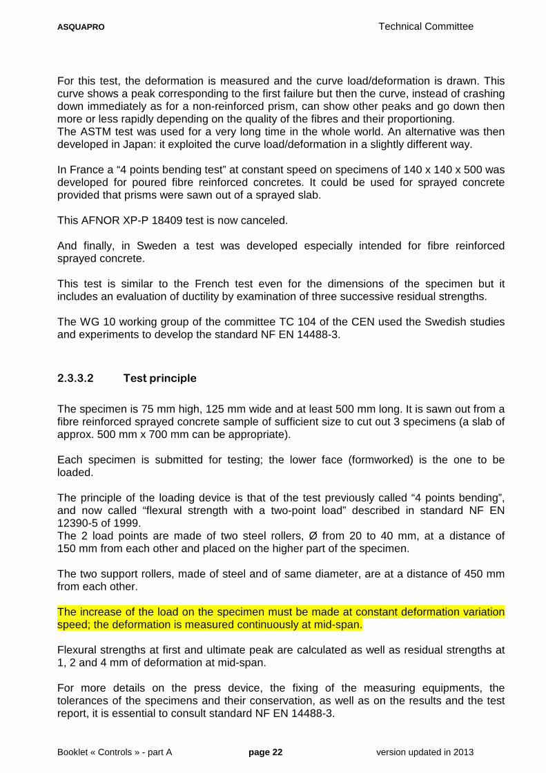
The specimen is 75 mm high, 125 mm wide and at least 500 mm long. It is sawn out from a fibre reinforced sprayed concrete sample of sufficient size to cut out 3 specimens (a slab of approx. 500 mm x 700 mm can be appropriate). Each specimen is submitted for testing; the lower face (formworked) is the one to be loaded. The principle of the loading device is that of the test previously called “4 points bending”, and now called “flexural strength with a two-point load” described in standard NF EN 12390-5 of 1999. The 2 load points are made of two steel rollers, Ø from 20 to 40 mm, at a distance of 150 mm from each other and placed on the higher part of the specimen. The two support rollers, made of steel and of same diameter, are at a distance of 450 mm from each other. The increase of the load on the specimen must be made at constant deformation variation speed; the deformation is measured continuously at mid-span. Flexural strengths at first and ultimate peak are calculated as well as residual strengths at 1, 2 and 4 mm of deformation at mid-span. For more details on the press device, the fixing of the measuring equipments, the tolerances of the specimens and their conservation, as well as on the results and the test report, it is essential to consult standard NF EN 14488-3.

ASQUAPRO Technical Committee
Booklet « Controls » - part A page 23 version updated in 2013
2.3.42.3.42.3.42.3.4 NF EN 14488NF EN 14488NF EN 14488NF EN 14488----4444 TESTING SPRAYED CONCTESTING SPRAYED CONCTESTING SPRAYED CONCTESTING SPRAYED CONCRETE:RETE:RETE:RETE: BOND STRENGTH BY BOND STRENGTH BY BOND STRENGTH BY BOND STRENGTH BY
DIRECT TENSIONDIRECT TENSIONDIRECT TENSIONDIRECT TENSION
2.3.4.1 Why such a test?
Since concrete has been spread on a support different than a formwork, the concrete/support adhesion value has been sought for. This last point is often considered to be more important than that of the intrinsic strength of sprayed concrete, in particular for the reinforcement and repair works of reinforced concrete. For these works, the adhesion between the existing structure and its reinforcement is of primary importance so that the whole structure behaves in a monolithic way (see chapter 3 of the booklet “Dimensioning”). The in situ test uses a tripod traction device with a bellows jack which is described in standard NF P 18-858 to test repair products applied in low thickness on a poured reference concrete. This test was initially used. It was very quickly proved that this test was not appropriate to measure the adhesion on an irregular surface. As an example, 10 specimens taken from a concrete slab covered with sprayed concrete, and tested in situ in traction with the tripod device, gave results varying from 0.2 to 0.8 MPa whereas for 5 specimens taken from the same test slab (of 1.20 m x 0.30 m) between the previous specimens, the adhesions measured in laboratory were between 3.4 and 3.6 MPa by using the direct tensile test. This phenomenon was well-known when the standard NF P 95-102 was written since the following remarks and recommendations appear in it: Two types of tests allow to determine the adhesion on the support: • an in situ test: wrenching by traction of specimens pre-cut in the coating and the support to be
tested
• a direct traction test: made in laboratory on specimens taken from the coating and the support to be tested.
This second kind of test is preferable to the first.
Two precautions are needed:
• the coring should not deteriorate the specimen; this supposes a coring machine in a good operating condition, well fixed on the wall and an adapted cutting tool (in the current state of knowledge, the appreciation of the coring material is only qualitative);
• the traction axis of the jack (in situ test) or of the traction machine (laboratory test) must match with the longitudinal axis of the specimen. This means that the testing equipment should be well adapted, in good condition, and a highly qualified personnel.
In this standard the test in a laboratory was recommended but the in situ test was not prohibited.

ASQUAPRO Technical Committee
Booklet « Controls » - part A page 24 version updated in 2013
The standard NF EN 14488-4 that we are examining only relates to the direct traction test realised in a laboratory on specimens taken from the structure. The in situ test is not quoted in this standard because it is not adapted to sprayed concrete; it is strongly not recommended.
2.3.4.2 Test principle
A specimen Ø from 50 to 100mm (d) and with a length ≥ 2 d is taken from the sprayed concrete layer and the support. The specimen is cut transversely so that its length = 2d and the adhesion zone is as close as possible to the middle of the test-tube. Steel tablets with a diameter equal to that of the specimen (± 1 mm) are stuck on the 2 modified ends and the test-tube is subjected to an increasing traction until it breaks. To obtain details on the tensile strength testing m achine, the steel tablets and their sticking, the tolerances of the specimens and their conservation, as well as on the results and the test report, it is essential to con sult the standard NF EN 14488-4.
On the left: the coring
On the right: the direct tensile test (Drawn by ASQUAPRO)
Core drill
Sawing
Sawing

ASQUAPRO Technical Committee
Booklet « Controls » - part A page 25 version updated in 2013
2.3.52.3.52.3.52.3.5 NF EN 14488NF EN 14488NF EN 14488NF EN 14488----5555 ---- ENERENERENERENERGY ABSORBING CAPABILGY ABSORBING CAPABILGY ABSORBING CAPABILGY ABSORBING CAPABILITY OF AITY OF AITY OF AITY OF A FIBRE FIBRE FIBRE FIBRE
REINFORCED SLABREINFORCED SLABREINFORCED SLABREINFORCED SLAB
The complete title of the standard is as follows: Testing sprayed concrete: Determination of energy a bsorbing capability of a fibre reinforced slab specimen
2.3.5.1 Why such a test?
The utility of a test allowing the study of the post-cracking behaviour of fibre concrete was mentioned in paragraph 2.3.3.1, about the tests carried out on prismatic test-tubes subjected to bending. In Sweden, the test was derived from the ASTM test but especially intended for fibre reinforced sprayed concrete. It was tested and gave rise to the standard NF EN 14488-3 which makes it possible to evaluate ductility by calculating the strength at first peak, at successive residual strengths and at ultimate strength. Meanwhile in France the SNCF, the fibres manufacturers and a laboratory of Grenoble, developed a very different test for which a fibre concrete square slab was sprayed to be tested under a centred bending stress. This test is sometimes called “punching test”; it produces the load/deformation curve, like the tests on prismatic test-tubes. It also makes it possible to evaluate the behaviour of fibre concrete, by calculating the energy progressively spent during the loading. The CEN/TC 104/WG 10 working group considered that these 2 tests gave different information but that they were both appropriate to control the quality and to define the classes of fibre reinforced sprayed concretes (see tables 2 and 3 of NF EN 14487-1). The French testing method was thus used to write the standard NF EN 14488-5. An alternative with circular slabs was not retained.
2.3.5.2 Test principle
A slab of 600 x 600 x 100 mm, fibre reinforced and sprayed in accordance with the standard NF EN 14488-1 is subjected to a load via a rigid steel square block placed at the centre of the slab. The deformation is measured. The curve load/deformation is measured and the test goes on until obtaining a deformation of at least 30 mm at the centre of the slab. A second curve is plotted from this curve, indicating the absorbed energy depending on the deformation. It is the energy absorbed for the deformation of 25 mm which is taken into account to characterize the fibre reinforced sprayed concrete. For all that relates to the testing machine and its control, the preparation of the test-tube, its loading, the expression of the results and the test report, it is advisable to refer to the standard NF EN 14488-5.

ASQUAPRO Technical Committee
Booklet « Controls » - part A page 26 version updated in 2013
2.3.5.3 Figure 1 of the standard
The square punch which does not show any dimension on this figure is 100 x 100 mm
Figures 2 and 3 of the standard
Note that in figure 3 of the standard, the energies are wrongly indicated in kilojoules and not in joules.
Sample loading configuration

ASQUAPRO Technical Committee
Booklet « Controls » - part A page 27 version updated in 2013
2.3.62.3.62.3.62.3.6 NF EN 14488NF EN 14488NF EN 14488NF EN 14488----6 MEASURE OF THE CON6 MEASURE OF THE CON6 MEASURE OF THE CON6 MEASURE OF THE CONCRETE THICKNESS ON ACRETE THICKNESS ON ACRETE THICKNESS ON ACRETE THICKNESS ON A
SUPPORTSUPPORTSUPPORTSUPPORT
The exact title of the standard is as follows: Testing sprayed concrete: Part 6: thickness of conc rete on a substrate
2.3.6.1 Comment
This test is certainly the least useful of all. Its only interest is to give a reference procedure to measure the sprayed thickness. It is indicated that in fresh concrete “a depth gauge is inserted in the sprayed concrete to measure its thickness” and that for hardened concrete, “the holes can be drilled or the specimens taken out as far as the substrate. The depth of the holes or the length of the extracted specimens is then measured”. It is then recommended to drill 5 holes separated by 600 ± 50 mm on 2 perpendicular lines or to take off specimens according to the same diagram. If more details are needed concerning measurements, the results and the test report, it is advisable to refer to the text of the standard.
2.3.72.3.72.3.72.3.7 NF EN 14488NF EN 14488NF EN 14488NF EN 14488----7777 FIBRE CONTENT OF FIBFIBRE CONTENT OF FIBFIBRE CONTENT OF FIBFIBRE CONTENT OF FIBRE REINFORCED SPRAYERE REINFORCED SPRAYERE REINFORCED SPRAYERE REINFORCED SPRAYED D D D
CONCRETECONCRETECONCRETECONCRETE
The exact title of the standard is as follows: Testing sprayed concrete: fibre content of fibre re inforced concrete
2.3.7.1 Why such a test?
It is explained in paragraph 1.3.5.1 that the fibre content of the concrete in place could be very different from the proportion recommended for the basic mixture and that it was therefore necessary to know this content from the moment of projection to avoid disappointments when receiving the results of the tests on hardened concrete (NF EN 14488-3 and 14488-5). For this reason the test on fresh concrete is the most important because it is the in situ content which determines the mechanical performances of hardened concrete, these performances that are known sometimes only after the works are finished. The measure of hardened concrete fibre content is nevertheless useful when tests on fresh concrete could not be carried out or when one wants to know the correlation between the in situ fibre content and the mechanical performances of hardened sprayed concrete.

ASQUAPRO Technical Committee
Booklet « Controls » - part A page 28 version updated in 2013
2.3.7.2 Test principle
“The fibres are extracted from a sample of hardened concrete (method A) or of fresh concrete (method B). The fibre content is measured from their mass and the volume of the concrete sample” (article 3 of the standard). For the two methods it is necessary to weigh the extracted fibres and to measure the volume of the sample.
2.3.7.2.1 Method A (on hardened concrete)
Three specimens with a diameter between 50 and 100 mm are taken from the in situ material or from a test slab. Their volume is calculated according to their measured dimensions or by weighing in the water, in accordance with EN 12350-6. Each specimen is crushed until complete disintegration to separate fibres from concrete. The magnetic fibres are then collected with a magnet. They are dried, cleaned and weighed to the nearest 0.1 g.
2.3.7.2.2 Method B (on fresh concrete)
Three samples from 1 to 2 kg (*) are cut out with a trowel, in situ or in a test slab. Their volume is weighed in the air and then in water (EN 12390-7). The density of the wet sample is then calculated. The fibres are withdrawn from the sample by washing on a sieve that catches the fibres. For synthetic fibres, the sample can be soaked with water (polypropylene fibres) or alcohol (for some other fibres) and be stired until the fibres float on the surface. Then they must be dried, cleaned and weighed to the nearest 0.1 g for steel fibres or to the nearest 0.01 g for polymer fibres. It is essential to consult the standard for more information on the sample selection, the results and the test report. (*) Actually the standard should be revised because the samples generally have a volume of 1 litre and thus weight between 2 and 3 kg.

ASQUAPRO Technical Committee
Booklet « Controls » - part A page 29 version updated in 2013
2.42.42.42.4 STANDARDISED TESTS NSTANDARDISED TESTS NSTANDARDISED TESTS NSTANDARDISED TESTS NONSPECIFIC TO SPRAYEONSPECIFIC TO SPRAYEONSPECIFIC TO SPRAYEONSPECIFIC TO SPRAYED CONCRETED CONCRETED CONCRETED CONCRETE
Tests which have existed for many years to measure and control some characteristics of poured concretes, can be used for sprayed concretes without adaptation. It is the case for example of the slump test (NF EN 12350-2) which makes it possible to evaluate the consistency of a fresh concrete (also called slump test with the Abrams cone), and which is used for sprayed concrete by wet process. For the tests which were not intended for sprayed concretes at the beginning but which can be applied, it is necessary to separate:
• the tests on fresh concrete from those on hardened concrete.
• for the tests on fresh concrete, those carried out before or after projection.
• The projection by dry process from the projection by wet process.
There are many tests but they are far from being all used in France. Only those usually used on sites and whose regulations refer to the French standards and rules are developed in this booklet. It is the case for the slump test (quoted above) and that of the slump-flow test (NF EN 12350-8). The other tests, standardised (NF) but little used for sprayed concrete such as for example the test from standard EN 12350-3 (Vebe test), are not quoted in the list of the standards possibly usable.
2.4.12.4.12.4.12.4.1 TESTS ON FRESH CONCRTESTS ON FRESH CONCRTESTS ON FRESH CONCRTESTS ON FRESH CONCRETEETEETEETE
2.4.1.1 Tests before projection
2.4.1.1.1 Dry process
The concrete sprayed by dry process mixes with its dampening water only at the moment of impact of the jet on the substrate. No tests on fresh concrete before projection can therefore exist for this method. Only measures on dry mixtures (manufactured and delivered in bags or silos) or on slightly wet mixtures (manufactured on site or in mixing plant with undried sand) can thus be done but obviously it is not “fresh concrete”. Nevertheless tests can be done on these dry mixtures before projection, for example their sieve analysis (after drying if the mixture contains undried sand), in order to control their conformity with the regulations.

ASQUAPRO Technical Committee
Booklet « Controls » - part A page 30 version updated in 2013
2.4.1.1.2 Wet process with dense flow
With this method, the water introduced during the mixing cannot flow out when concrete goes through the pump or the transfer pipe. Thus, almost all the water remains in the concrete in place.
Measurement of water content The only water loss due to a possible vaporization between the nozzle and the receiving surface can be regarded as negligible. Then the concrete water content could be measured (before as well as after projection) but currently there is no standardised method to take this measure.
Measurement of density Before projection, this measure can be taken, completely complying with the regulations of the standardised test NF EN 12350-6, on a sample from at least 5 dm3 taken out before the pumping and compacted by vibration or manually, according to the standard. Referring to the foreword of this standard which specifies “a smaller volume can be appropriate for the tests of production control” and taking account of the fact that the grain size of sprayed concretes are smaller than this of poured concretes, a minimal volume of 2 dm3 can be recommended. However, even with this reduced volume of 2 dm3, this lab test, almost useless for the control, is never prescribed to evaluate a sprayed concrete on site.
Measurement of subsidence The standardised test for fresh concrete most employed on French sites is that of standard NF EN 12350-2 concerning the slump test. This test allows indeed not only to check that the consistency grade of a concrete ready to be sprayed is in conformity with the prescribed consistency grade but also to collect useful information on its pumpability. The test is easy to realise and its results are trustful: these points largely contributed to its development and its longevity. It is practised on a sampling taken from the place the concrete is delivered (exit of concrete mixer or dumper, or ready-mix plant skip or drum). The concrete is then introduced into the cone, it is compacted by tapping and removed from the mould according to the regulations of the standard (number of layers, tapping mode, demoulding time…) and the subsidence is measured. If the subsidence is higher than 20 cm, it is recommended to carry out the slump-flow test described in the following paragraph. For more details on the measures of the cone as well as on the test procedure and its exploitation, it is advisable to refer to standard NF EN 12350-2.
ASQUAPRO Technical Committee
Booklet « Controls » - part A page 31 version updated in 2013
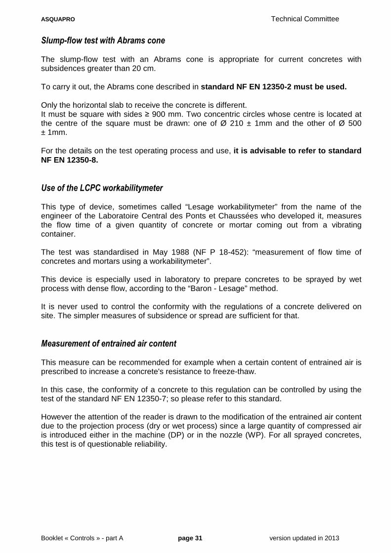
Slump-flow test with Abrams cone The slump-flow test with an Abrams cone is appropriate for current concretes with subsidences greater than 20 cm. To carry it out, the Abrams cone described in standard NF EN 12350-2 must be used. Only the horizontal slab to receive the concrete is different. It must be square with sides ≥ 900 mm. Two concentric circles whose centre is located at the centre of the square must be drawn: one of Ø 210 ± 1mm and the other of Ø 500 ± 1mm. For the details on the test operating process and use, it is advisable to refer to standard NF EN 12350-8. Use of the LCPC workabilitymeter This type of device, sometimes called “Lesage workabilitymeter” from the name of the engineer of the Laboratoire Central des Ponts et Chaussées who developed it, measures the flow time of a given quantity of concrete or mortar coming out from a vibrating container. The test was standardised in May 1988 (NF P 18-452): “measurement of flow time of concretes and mortars using a workabilitymeter”. This device is especially used in laboratory to prepare concretes to be sprayed by wet process with dense flow, according to the “Baron - Lesage” method. It is never used to control the conformity with the regulations of a concrete delivered on site. The simpler measures of subsidence or spread are sufficient for that.
Measurement of entrained air content This measure can be recommended for example when a certain content of entrained air is prescribed to increase a concrete's resistance to freeze-thaw. In this case, the conformity of a concrete to this regulation can be controlled by using the test of the standard NF EN 12350-7; so please refer to this standard. However the attention of the reader is drawn to the modification of the entrained air content due to the projection process (dry or wet process) since a large quantity of compressed air is introduced either in the machine (DP) or in the nozzle (WP). For all sprayed concretes, this test is of questionable reliability.

ASQUAPRO Technical Committee
Booklet « Controls » - part A page 32 version updated in 2013
2.4.1.1.3 Wet process with diluted flow
With this method, the subsidence and spread measures make it possible to control the conformity with the regulations of the delivered concrete but it cannot give an indication on the characteristics of the concrete after projection because in diluted flow, the concrete can have lost a significant part of its water per draining after its way at high speed in an air flow.
2.4.1.2 Tests on fresh concrete after projection
After projection, fresh concrete has rheological (consistency) and physical (density, compactedness…) characteristics due to the implementation process. For the dry process, the standardised tests to measure consistency, compactedness and density should be carried out after an in situ sampling from fresh concrete followed by an introduction in a container by tamping or vibration. In consequence, they cannot be used because with this method, the characteristics of concrete, altered during the sampling, are different from those of the implemented concrete. So there is currently no standardised test after projection, applicable to fresh concrete implemented by projection by dry process. The standardised procedures concerning the measures of density and consistency cannot be applied to projection by wet process by dense and diluted flow since they all require compactions different from those obtained by the projection. These measures are not practised because of their low level of interest and also because the projection techniques by wet process bring just few modifications to concrete.
2.4.2.2.4.2.2.4.2.2.4.2. TESTS ON HARDENEDTESTS ON HARDENEDTESTS ON HARDENEDTESTS ON HARDENED CONCRETECONCRETECONCRETECONCRETE
These tests enumerated in table 8 of standard NF EN 14487-1 of March 2006 in its paragraph 5.5 heading “Requirements relating to hardened sprayed concrete” are feasible if it is possible to extract or saw out sprayed concrete test-tubes (in boxes or in situ). They are the measurements of compressive strength, density, elasticity modulus, flexural strength, water penetration, freezing-thawing. For fibre reinforced sprayed concretes, the tests are the following: • Fibre content in the concrete in place (EN 14488-7), • Flexural strength on prism (EN 14488-3) • Bending centrered on a slab (EN 14488-5 energy absorption capacity).
ASQUAPRO Technical Committee
Booklet « Controls » - part A page 33 version updated in 2013
2.52.52.52.5 NONNONNONNON----STANDARDISEDSTANDARDISEDSTANDARDISEDSTANDARDISED TESTS USABLE FOR SPRTESTS USABLE FOR SPRTESTS USABLE FOR SPRTESTS USABLE FOR SPRAYED CONCRETEAYED CONCRETEAYED CONCRETEAYED CONCRETE
2.5.12.5.12.5.12.5.1 TESTS ON FRESH CONCRTESTS ON FRESH CONCRTESTS ON FRESH CONCRTESTS ON FRESH CONCRETE SPECIFIC TO SPRAETE SPECIFIC TO SPRAETE SPECIFIC TO SPRAETE SPECIFIC TO SPRAYED CONCRETEYED CONCRETEYED CONCRETEYED CONCRETE
2.5.1.1 Measurement of density after projection
2.5.1.1.1 Dry process
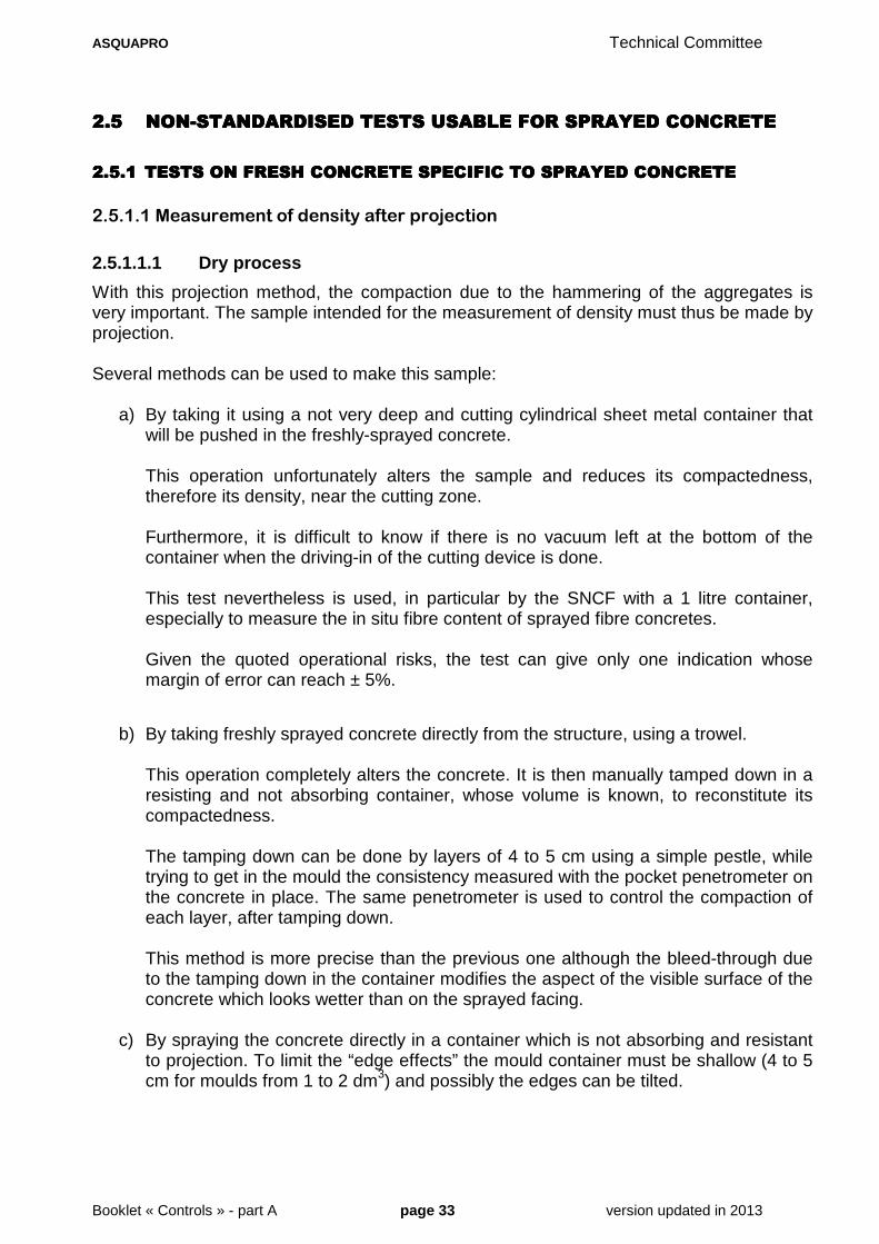
With this projection method, the compaction due to the hammering of the aggregates is very important. The sample intended for the measurement of density must thus be made by projection. Several methods can be used to make this sample:
a) By taking it using a not very deep and cutting cylindrical sheet metal container that will be pushed in the freshly-sprayed concrete.
This operation unfortunately alters the sample and reduces its compactedness, therefore its density, near the cutting zone. Furthermore, it is difficult to know if there is no vacuum left at the bottom of the container when the driving-in of the cutting device is done. This test nevertheless is used, in particular by the SNCF with a 1 litre container, especially to measure the in situ fibre content of sprayed fibre concretes. Given the quoted operational risks, the test can give only one indication whose margin of error can reach ± 5%.
b) By taking freshly sprayed concrete directly from the structure, using a trowel.
This operation completely alters the concrete. It is then manually tamped down in a resisting and not absorbing container, whose volume is known, to reconstitute its compactedness.
The tamping down can be done by layers of 4 to 5 cm using a simple pestle, while trying to get in the mould the consistency measured with the pocket penetrometer on the concrete in place. The same penetrometer is used to control the compaction of each layer, after tamping down.
This method is more precise than the previous one although the bleed-through due to the tamping down in the container modifies the aspect of the visible surface of the concrete which looks wetter than on the sprayed facing.
c) By spraying the concrete directly in a container which is not absorbing and resistant
to projection. To limit the “edge effects” the mould container must be shallow (4 to 5 cm for moulds from 1 to 2 dm3) and possibly the edges can be tilted.
ASQUAPRO Technical Committee
Booklet « Controls » - part A page 34 version updated in 2013
With this method, the compaction is well taken into account and the nests of losses in the angles are negligible (even null when the edges are tilted). The volume of the collecting container can be easily determined by weighing to the nearest gram once it was filled with water.
The surfacing of the front side is the only difficulty. It must be cut with a beveled levelling ruler moved on the edges of the mould with an alternate shearing motion. The possible wrenchings, due to fine gravels or fibres must be filled and smoothed with a trowel.
The method “c” is the one which is recommended to date but the evaluation of the concrete density remains delicate.
2.5.1.1.2 Wet process
With this projection method, the compaction due to the hammering of the aggregates is less important than in the dry process but it exists. The sample intended for the measurement of the density must thus also be carried out by projection. The risk of trapping losses being weak, it becomes possible to spray directly in a 5 dm3 container (the exemption for 2 dm3 is not advisable in this case) while following the same precautions as for the method “c” above. In consequence, the testing method can largely be based on the European standard EN 12350-6 without however being completely respected since in this standard, the taken sample must be compacted by vibration or manually. Apart from the regulations concerning compaction, all the other recommendations of the standard EN 12350-6 can be applied including the data relating to fidelity of its table 1. More simply, the method “c” described above for the dry process, can be used.
2.5.1.2 Measurement of consistency
2.5.1.2.1 Dry process
The consistency of the sample cannot be given the same way as that obtained by compaction during projection. The control which is qualitative and/or quantitative is done on the unaltered concrete.
• Qualitative control Very simple manual tests have always been practised by the experienced nozzlemen who appreciate the insertion resistance with their thumb (or with a steel point of Ø 2 to 4 mm) in the concrete.
• Quantitative control It can be carried out for example using a penetrometer measuring reactions going from 0 to 11 daN and whose conical pointed-tip has an angle of 60° and a base of Ø 8 mm. Different pointed-tips can also be appropriate.

ASQUAPRO Technical Committee
Booklet « Controls » - part A page 35 version updated in 2013
Details on the use of this type of pocket penetrometer are given in the booklet “Controls - part B”. This test can be prescribed as a control test for people who do not have the experience of a qualified nozzleman.
2.5.1.2.2 Wet process
No consistency measuring device especially adapted to projection by wet process is currently sold but some were developed by laboratories, sometimes by modifying materials designed for other uses. For example, for very fluid concretes, a cone similar to those used to measure the grouts viscosity (Marsh cone) but equipped with a very large nozzle (20 to 50 mm) and possibly prolonged by an elbow, can be used. The penetration strength of a rubber pipe in a fluid easily workable concrete can also be measured with a dynamometer such as the pocket penetrometer described in the previous paragraph (2.5.1.2.1.). Compared to the standardised slump test, the 2 measures previously quoted have the advantage of informing about the “pumpability” of the concrete which must be introduced into the pump and pushed in the pipe. In addition, they are quickly and easily done.

ASQUAPRO Technical Committee
Booklet « Controls » - part A page 36 version updated in 2013
2.5.22.5.22.5.22.5.2 TESTS ON FRESH CONCRTESTS ON FRESH CONCRTESTS ON FRESH CONCRTESTS ON FRESH CONCRETE NONSPECIFIC TO SETE NONSPECIFIC TO SETE NONSPECIFIC TO SETE NONSPECIFIC TO SPRAYED CONCRETEPRAYED CONCRETEPRAYED CONCRETEPRAYED CONCRETE
2.5.2.1 Measurement of fresh concrete consistency
Many non-standardised tests were developed to evaluate the consistency and various other properties of fresh concrete, poured in a formwork and then set up by manual compaction or vibration. For the dry process, these tests could be carried out only after projection but as they do not have any utility in most cases, they are never prescribed to control the quality of sprayed concretes on buildings sites. For the wet process with diluted flow, the pumpability problem not being a critical point, the tests on fresh concrete before projection are useless and those after projection having only a low interest are not used on building sites as for the dry process.
For the wet process with dense flow, the consistency test is on the other hand very useful before projection to check that the concrete intended to be introduced into the pump is in conformity with the regulations and that it can be pumped and transported into the pipe to the nozzle, and then sprayed. After projection, the tests can be done but as for other methods, their interest being low, they are never required for controls on building sites. The majority of non-standardised tests on fresh concrete, initially designed for poured concretes and usable for sprayed concrete with sometimes an adaptation of sampling, generally give relevant and reliable results as long as they are carried out according to a precise procedure of course, defined by the equipment manufacturer or by the laboratory who developed it. Taking into account what was previously specified about the feasibility and the utility of tests on fresh concrete to control sprayed concretes, only those concerning the measurements of consistency and/or manoeuvrability applicable to the wet process and really practised on French building sites are summarily described in the following paragraphs.
2.5.2.1.1 Test using a “plate plasticimeter”
This test is the first quoted because the device it uses is light, affordable and the measurement is quickly done. For these reasons it is by far the most used on building sites after the standardised slump test NF EN 12350-2.
The device consists of a rod provided with plates at its lower end and with a dynamometer with a rotating handle at its top. When the rod has been driven down into the concrete until the plates disappear in it, the handle is turned manually by a half-turn. This handle is linked to the rod by a system including the measurement device.
ASQUAPRO Technical Committee
Booklet « Controls » - part A page 37 version updated in 2013
The rotational movement of the handle is transmitted to the rod via a coil spring fitted to the rod by one of its ends and to the handle by the other end. The maximum deformation of the spring, which depends on the resistance encountered by the plates during their rotation in the concrete, can be measured and read directly on the handle thanks to an index. The link between the values measured and those of the slump test (NF EN 12350-2) being satisfactory for current concretes, the manufacturer of the device graduated the reading scale in centimetres of subsidence. The choice of this unit can be justified because a change of operator little affects the link and the estimation of concretes consistency in centimetres of subsidence is the most commonly used in France. Nevertheless, it is questionable first because the plasticimeter measures a strength whereas the slump test measures a deformation but especially because the information given by the plasticimeter can be enough. For example this information could be translated into daN or quite simply regarded as a shearing or viscosity index without dimension. By applying this last proposal, the index measured in a few seconds allows to estimate the suitability of concrete for pumping and spraying as well if not better than the standardised slump test. The test can be frequently done, for example several times during the unloading of a concrete mixer truck. This allows, when the index reaches a value at which the person in charge for projection know there is a risk of blockage, to make a slump test and to stop the provisioning of the pump if it is confirmed that the concrete is not in conformity anymore with the regulation concerning consistency. In a nutshell, the plasticimeter with plates is very useful on building sites to frequently control the concrete pumpability and must be confirmed by a standardised test when it revealed that the limits of the prescribed consistency grade were likely to be exceeded and that there is a risk of litigation for nonconformity. Let us recall that the plasticimeter with plates should not be used for mortars or very fluid sand concretes which have subsidences measured with the Abrams cone higher than 20 cm (EN 12350-2). In this case the slump-flow test with Abrams cone (NF EN 12350-8) described in the paragraph 2.4.1.1 .2 can be used.
2.5.2.1.2 Test using a “Pompabilimeter”
The aptitude of a very fluid concrete for being pumped and being introduced into a pipe of relatively low diameter in order to be sprayed is a property which is very important to know before the pump is started to propel this concrete towards the nozzle. It was seen that the plasticimeter with plates could be used but that it was not appropriate for very fluid concretes. The word “pompabilimeter” which is used in this guide allows to evaluate the aptitude of the concrete to be quickly pumped and especially transported in a pipe of low diameter (25 to 50 mm) on a distance from 50 to 150 m or more. This neologism has the advantage of not requiring a definition.

ASQUAPRO Technical Committee
Booklet « Controls » - part A page 38 version updated in 2013
As it was indicated before, for measures of consistency before projection by wet process, it is possible to used tests for self-placing concretes but the “pompabilimeter” which measures the pumpability in a few seconds using a simple pocket penetrometer is most practical. With suitable ends it makes it possible to test a traditional mixture as well as a very fluid sand concrete.
Measurement with a pocket “pompabilimeter” before the loading of the pump
2.5.2.1.3 Other tests
To measure the consistency of fresh concrete, some laboratories devices were developed such as field vane testers and rheometers, but their use for controls on site at the time of projection is not possible. A small pocket field vane tester exists. It could be used for controls on site just like the pompabilimeter described in the previous paragraph. However, comparison tests for feasibility, repeatability and determination of the consistency range limits still have to be done before recommending its use.
2.5.32.5.32.5.32.5.3 TESTS ON HARDENED TESTS ON HARDENED TESTS ON HARDENED TESTS ON HARDENED CONCRETE NONSPECIFICCONCRETE NONSPECIFICCONCRETE NONSPECIFICCONCRETE NONSPECIFIC TO SPRAYED TO SPRAYED TO SPRAYED TO SPRAYED
CONCRETECONCRETECONCRETECONCRETE
2.5.3.1 Non-destructive tests on building site
2.5.3.1.1 Sonic echo-sounding with a hammer
This inspection by manual echo-sounding with a hammer is recommended in the standards of many nations and in particular in France (NF P 95-102), often in a systematic way, on the whole sprayed surface of a repaired or reinforced work. This hammer inspection aims to detect and locate the unbonded zones as soon as the sprayed concrete is sufficiently hardened (for example after 24 hours). Unfortunately this recommendation is not accompanied by any testing method.

ASQUAPRO Technical Committee
Booklet « Controls » - part A page 39 version updated in 2013
The hammer inspection remains nevertheless the most effective mean to detect the unbonded sprayed concrete plates that are likely to be detached. It also makes it possible to determine the zones well stuck but emitting what is generally described as a “hollow sound”. These zones can easily be delimited with a decametric precision but the characterization of the sounds located “with the ear” is subjective and badly defined. A guide describing the procedure of the inspection (types of hammers, spacing of strikes, etc.) and defining the terms allowing to better characterize the sounds, is developed in the booklet “Controls - part B”
2.5.42.5.42.5.42.5.4 TESTS ON HARDENED COTESTS ON HARDENED COTESTS ON HARDENED COTESTS ON HARDENED CONCRETE SPECIFIC TO SNCRETE SPECIFIC TO SNCRETE SPECIFIC TO SNCRETE SPECIFIC TO SPRAYED CONCRETEPRAYED CONCRETEPRAYED CONCRETEPRAYED CONCRETE
2.5.4.1 Strength at young ages
Since sprayed concrete has been used for underground works in particular for what was called the “New Austrian Method”, a sufficient concrete resistance is always sought to obtain a support within the shortest possible time. Unfortunately, we saw that drilling out a sample is almost impossible as long as the compressive strength of the concrete does not exceed 10 MPa because aggregates come off and turn with the diamond corer. Various methods were thus imagined to solve this problem in order to estimate the resistance of a young sprayed concrete, apart from those developed in Austria for underground works (used in standard NF EN 18488-2 and described in this booklet in paragraph 2.3.2). The following procedure which was developed by the SNCF is used:
2.5.4.1.1 G.I.R. Procedure (Guaranteed Initial Resi stance)
For a reason different from that of the fast creation of a support, the SNCF asked the companies to spray - for works in tunnels which are in operation - a concrete quickly getting a high resistance so that the circulation of the trains can be restored approximately 3 hours after its projection. The G.I.R. procedure is used to qualify dry basic mixtures, manufactured in plants and allowing to obtain a resistance ≥ 3 MPa after 3 hours and at 10°C. Therefore, for the tests at 3, 5 and 24 hours, the coring is replaced by the sawing of 10 cm x 10 cm cubes out of sprayed slabs. The test-tubes intended for longer-term tests (at 7, 28 and possibly 90 days) will be cored out. To be on the SNCF list of suitable candidates and for on-site controls, the results to obtain are as follows: At 3 hours: ≥ 3 MPa if the temperature is of 10°C ≥ 1.5 MPa if t=2°C At 24 hours: ≥ 10 MPa At 28 days: ≥ 25 MPa

ASQUAPRO Technical Committee
Booklet « Controls » - part A page 40 version updated in 2013
3. MINIMUM FREQUENCIES OF CONTROLS
The samplings minimum frequencies are defined in table 12 of standard NF EN 14487-1. It is essential to refer to this very important tab le. In this table, 3 “categories” of levels of inspection are indicated: • Category 1 relates to the works requiring only a low level of inspection
• Category 2 relates to the works requiring a medium level of inspection
• Category 3 relates to the works requiring the highest level of inspection
3.13.13.13.1 CATEGORIES OF INSPECCATEGORIES OF INSPECCATEGORIES OF INSPECCATEGORIES OF INSPECTIONTIONTIONTION
These categories take account of the risks incurred by the works (stability, longevity), by their users and their residents and by their environment (nearby structures, dwellings, etc.). Given the great diversity of the works, their environment and their significant number of material and human risks, it was not possible to determine the categories of inspection in an exhaustive way. Nevertheless, some examples were given in appendix A (informative) of standard NF EN 14487-1. They make it possible to determine these categories of inspection for various types of works subjected to various levels of risks. These examples of categories of inspection appear in the tables A.1, A.2, A.3 and A.4 of appendix A of this standard, to which it is essential to refer.
3.1.13.1.13.1.13.1.1 TABLE A1TABLE A1TABLE A1TABLE A1
Repair or reinforcement of structures and non-loadb earing elements • Category 1: can apply when durability requirements are minor and when risks for users
and residents are weak (for example in nonurban zone)
• Category 2: can apply when durability requirements are moderate and when risks for users and residents are medium (for example houses and small blocks of flats)
• Category 3: applies when durability requirements and risks for users and residents are high (for example hospitals, tunnels with heavy traffic).

ASQUAPRO Technical Committee
Booklet « Controls » - part A page 41 version updated in 2013
3.1.23.1.23.1.23.1.2 TABLE A2TABLE A2TABLE A2TABLE A2
Repair or reinforcement of structures and loadbeari ng elements • Category 1: cannot apply.
• Category 2: can apply for example to sewers in small urban zones
• Category 3: can apply for example to hospitals, large blocks of flats
3.1.33.1.33.1.33.1.3 TABLE A3TABLE A3TABLE A3TABLE A3
Supports • Category 1: can apply for example to the stabilization of low slopes
• Category 2: can apply for example to sprayed concrete for tunnels temporary support
• Category 3: can apply for example to tunnels with heavy traffic
3.1.43.1.43.1.43.1.4 TABLE A4TABLE A4TABLE A4TABLE A4
Independent structures • Category 1: can apply for example to decorative factitious rocks
• Category 2: can apply for example to small swimming pools
• Category 3: can apply for example to factitious rocks open to the public Note: Sprayed concrete works such as free shape houses, swimming pools, bobsleigh tracks, climbing walls, factitious rocks, etc… were previously called “new works” in France. This denomination was in particular used in the booklets “presentation” and “dimensioning” of the on-line guide on the ASQUAPRO website before “independent structures” was adopted in the final version of the EN standard 14487-1. Note: The definition of “independent structures” was created, at the request of France, in standard NF EN 14487-1 (paragraph 3.5.1).