Bonfiglioli Servomotor BMD - SKS SWEDEN€¦ · About us 3 Bonfiglioli, one name for a large...
64
BMD Permanent Magnet AC Synchronous Motors
Transcript of Bonfiglioli Servomotor BMD - SKS SWEDEN€¦ · About us 3 Bonfiglioli, one name for a large...

BMDPermanent Magnet ACSynchronous Motors

Power, controland green solutions

About us3
Bonfiglioli, one namefor a large international group.
It was back in 1956 that Clementino Bonfiglioli established in Bologna, Italy, the company that still bears his name. Now, some fifty years later, the same enthusiasm and dedication is driving Bonfiglioli to become the world’s top name in power transmission and control solutions. Through directly controlled subsidiaries and production plants around the world, Bonfiglioli designs, manufactures and distributes a complete range of gearmotors, drive systems and planetary gearboxes, and boasts the most integrated offering on the market today.
Now, to emphasise its commitment to health, safety and environmental sustainability, Bonfiglioli is adding the term “green” to the description of its offering.
This commitment can be seen too in the Group’s new trademark, made up of three shapes and colours identifying Bonfiglioli’s three main business areas - Power, Control & Green Solutions and symbolising a set of values that includes openness and respect for other cultures.
In a market in which excellent product quality alone is no longer sufficient, Bonfiglioli also provides experience, know-how, an extensive sales network, excellent pre-sales and after-sales service and modern communication tools and systems to create high level solutions for industry, mobile machinery and renewable energy.

Bonfigliolisolutions
wind
photovoltaic
industrial
mobile

5
Innovative solutionsfor industrial field.
Bonfiglioli Riduttori today is one of the top brandsin the power transmission industry.The company’s success is the result of a businessstrategy that relies on three fundamental factors:know-how, innovation and quality.The complete range of Bonfiglioli brandgearmotors offers excellent technical characteristics and guarantees the highestperformance. Substantial investment and technicalexpertise have enabled the company to achieve anannual production output of 1600000 units usingcompletely automated processes.Certification of the company’s Quality System by TÜV is proof of the high quality standards achieved.With the acquisition of the Vectron brand,Bonfiglioli is now established as leader of theindustrial automation sector.
Bonfiglioli offers excellent and integrated solutions for power transmission and control. We design, manufacture and distribute a complete range of motors, gearmotors, drive systems and planetary gearboxes.Our solutions are used in a vast range of applications all over the world, in industry, mobile machinery and automation, to improve the quality of life and work on a daily basis.
Over the last several years, automation industry has undergone significant development. The constant demand for higher performance in an area where mechanical and electronic sectors work in synergy to achieve reliability, performance, cost-effectiveness and ease of installation, has prompted Bonfiglioli Riduttori to develop an integrated product in which the mechanical speed reducer, brushless motor and electronic frequency converter coexist in a single compact unit.
Bonfiglioli Vectron delivers products and services for completely integrated inverter solutions.These solutions complement Bonfiglioli’s power transmission and control offering to the industrial sector.
Since 1976, Bonfiglioli Trasmital’s know-how in the power transmission industry has focused on special applications offering 100% reliability in the manufacturing of gearmotors for mobile machinery.This includes the full range of slew and wheel drive applications and gearboxes for wind turbine pitch and yaw drive systems. Today Bonfiglioli Trasmital stands at the forefront of the industry as a key partner to top manufacturers worldwide.

7
Advanced technologies for all industrial fields.
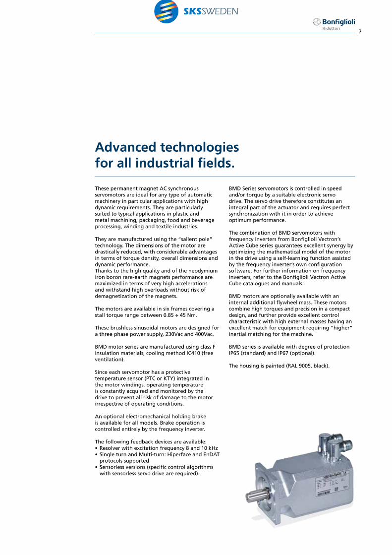
These permanent magnet AC synchronous servomotors are ideal for any type of automatic machinery in particular applications with high dynamic requirements. They are particularly suited to typical applications in plastic and metal machining, packaging, food and beverage processing, winding and textile industries.
They are manufactured using the “salient pole” technology. The dimensions of the motor are drastically reduced, with considerable advantages in terms of torque density, overall dimensions and dynamic performance. Thanks to the high quality and of the neodymium iron boron rare-earth magnets performance are maximized in terms of very high accelerations and withstand high overloads without risk of demagnetization of the magnets.
The motors are available in six frames covering a stall torque range between 0.85 ÷ 45 Nm.
These brushless sinusoidal motors are designed for a three phase power supply, 230Vac and 400Vac. BMD motor series are manufactured using class F insulation materials, cooling method IC410 (free ventilation).
Since each servomotor has a protective temperature sensor (PTC or KTY) integrated in the motor windings, operating temperature is constantly acquired and monitored by the drive to prevent all risk of damage to the motor irrespective of operating conditions.
An optional electromechanical holding brake is available for all models. Brake operation is controlled entirely by the frequency inverter.
The following feedback devices are available:• Resolver with excitation frequency 8 and 10 kHz • Single turn and Multi-turn: Hiperface and EnDAT
protocols supported• Sensorless versions (specific control algorithms
with sensorless servo drive are required).
BMD Series servomotors is controlled in speed and/or torque by a suitable electronic servo drive. The servo drive therefore constitutes an integral part of the actuator and requires perfect synchronization with it in order to achieve optimum performance.
The combination of BMD servomotors with frequency inverters from Bonfiglioli Vectron’s Active Cube series guarantees excellent synergy by optimizing the mathematical model of the motor in the drive using a self-learning function assisted by the frequency inverter’s own configuration software. For further information on frequency inverters, refer to the Bonfiglioli Vectron Active Cube catalogues and manuals.
BMD motors are optionally available with an internal additional flywheel mass. These motors combine high torques and precision in a compact design, and further provide excellent control characteristic with high external masses having an excellent match for equipment requiring “higher” inertial matching for the machine.
BMD series is available with degree of protection IP65 (standard) and IP67 (optional).
The housing is painted (RAL 9005, black).

8
Sensorless servo drive
Bonfiglioli Agile drive matches with Permanent Magnet AC syncronous motor technology by featuring a sensorless control of these motors without feedback.Standard applications that are sensitive to dimensions and energy saving will first benefit from Permanent Magnet AC synchronous motors sensorless driven by Agile.
Sensorless Servo Drive is expected to be a competitive “package”.In brushless motor control, the exact angular position of the rotor must be known at all times for the drive to commutate the inverter phases.The conventional method for tracking rotor position is to incorporate an encoder or resolver inside the servomotor to provide the drive with the necessary electrical signals. This however, requires extra cabling, devices and controls.Thanks to innovative technology, Bonfiglioli Agile drives can control brushless servomotors without the need of sensors, eliminating the cost of superfluous components, wiring, devices and controls.Bonfiglioli Agile drives use efficient algorithms to estimate the instantaneous angular position of
the motor shaft from measurements of the current absorbed by the motor. By combining analytic techniques to reconstruct the electrical status of the motor and functional analysis of its magnetic circuit, Bonfiglioli Agile drives provide effective speed and torque vector control.
There are several benefits to eliminate electromechanical position sensors:• Energy savings and compactness when compared to
conventional solutions based on induction motors• Wide Constant Torque Speed Range when compared
to conventional solutions based on induction motors• Reliability improvement of the system• Eliminates the criticalities inherent in sensors• Simplifies the control system• Temperature limits on feedbacks• Compact applications, where is not possible to
accommodate position sensors• Overall cost reduction• Wiring reduction
The standard sensorless motor is provided of a 1 meter cable. It corresponds to the variants designation SEN P2. It is also available the possibility to have an 8-pin power connector by
selecting the SEN P1/P1N variant. In both cases the field related to the signal connector remains blank.
Speed or torque
reference
Agile
Vectorcontrol
PWM Power
Position reconstruction
SensorlessPMSM
SpeedTorque
Calculatedposition Po
wer
Servomotor
Agile
NO
fee
db
ack
Variant SEN P2Variant SEN P1

9
Standards and directives
Symbols and units of measure
BMD motors are manufactured in accordance with applicable standards and Directive listed in the following tables.
StandardIEC 60034-1, EN 60034-1Rotating electrical machinesPart 1: Rating and performance
IEC 60034-5, EN 60034-5Rotating electrical machinesPart 5: Degrees of protection provided by the integral design of rotating electrical machines (IP code) - Classification
IEC 60034-6, EN 60034-6Rotating electrical machinesPart 6: Methods of cooling (IC Code)
IEC 60034-8, EN 60034-8Rotating electrical machinesPart 8: Terminal markings and direction of rotation
IEC 60034-14, IEC 60034-14Rotating electrical machinesPart 14: Mechanical vibration - Measurement, evaluation and limits of vibration severity
IEC 60072-1Dimensions and output series for rotating electrical machines - Part 1
IEC TS 60034-25Rotating electrical machinesPart 25: Guidance for the design and performance of a.c. motors specifically designed for converter supply
DirectivesLow Voltage Directive: 2006/95/EC
The BMD servomotors series comply with UL/CSA standards for the North American market (UL file number E358266).
UL 1004-1Rotating Electrical MachinesGeneral Requirements
UL 1004-6Servo and Stepper Motors
CSA C22.2 No. 100Motors and Generators
Symbol U.m. Description
nn[min-1] Rated speed
Mn [Nm] Rated torque
Pn [kW] Rated power
In [A] Rated current
M0 [Nm] Stall torque
I0 [A] Stall current
Mmax [Nm] Max torque
Imax [A] Max current
KT [Nm/A] Torque constant
Kc [V/1000min-1] Back EMF constant
Rpp [W] Stator phase-phase resistance
Lpp [mH] Stator phase-phase inductance
tel [ms] Electric time constant
ttherm [min] Thermal time constant
JM [kgm2 x 10-4] Motor moment of inertia
mM [kg] Motor mass without brake
Jb [kgm2 x 10-4] Brake moment of inertia
mb [kg] Brake mass
Mb [Nm] Brake torque
Pb [W] Brake electrical power at 20°C
Vb [V] Brake DC voltage
Ib [A] Brake current
mMB [kg] Motor mass with brake
t1 [ms] Brake engaging time
t2 [ms] Brake release time

10
Bonfiglioli permanent magnet synchronous motors range
The Bonfiglioli permanent magnet synchronous motors are available in six sizes with stall torque comprises between 0.85 ÷ 45 Nm.
BMD servomotorBonfiglioli Permanent Magnet High DensityProduct Line Up• Competitive technology• Low inertia• Highest dynamics;• High torque density;• Precision; • Compact design• Compatibility with gears & inverters
BMD seriesPermanent Magnet AC Motors
7.2BMD 102
4.4BMD 82
3.2
2.2
BMD 65 1.7
0.85
22
34BMD 170
BMD 14516.8
14BMD 118
10.2
9.6
45

11
Product designation of Bonfigliolipermanent magnet synchronous motors
BMD servo motors are technically identified by their designation. This consists of a succession of alphanumeric characters, whose positions and values conform to precise rules and define the characteristics of the product.
The complete designation provides a unique identification of the exact servomotor configuration.
The designation is made up of two main parts, containing fields for:
- BASIC variants- OPTIONAL variants
Both the BASIC variant and OPTIONAL variant sections of the designation are divided into fields, each of which defines a particular design feature of the motor.
All basic variant and optional variant fields can assume only one value at a time. These values are selected from a limited set of pre-defined values for each field in the designation.
Is mandatory to select one of the possible choices in all variants fields. The variant can be missed only where a blank is a possible choice.
Housing of BMD servomotors is painted RAL 9005, black.
A brief overview of the available combinations of the basic variants such as motor size, motor stall torque, nominal voltage and nominal speed can be found in the following table.
BMD 65 BMD 82 BMD 102 BMD 118 BMD 145 BMD 170
0.85Nm
1.7Nm
2.2Nm
3.2Nm
4.4Nm
7.2Nm
9.6Nm
10.2 Nm
14Nm
16.8 Nm
22Nm
34Nm
45Nm
400 V
1600 rpm X X X X X X X X X X X X
3000 rpm X X X X X X X X X X X X X
4500 rpm X X X X X X X X X X X
5500 rpm X X X X X X X X X X X
6000 rpm X X X X X X X X X X
230 V
1600 rpm X X X X X X X X X X X X
3000 rpm X X X X X X X X X X X X
4500 rpm X X X X X X X X
5500 rpm X X X X X X X X
6000 rpm X X X X X X X

12
Product designation ofBonfiglioli servomotors
Basic Variants
65BMD 1.7 3000 400 63 9
Motor rated speed (3)
1600 (min-1)3000 (min-1)4500 (min-1)5500 (min-1)6000 (min-1)
Mechanical interface (2)
63 size 6575 size 65100 size 82, 102115 size 82, 102130 size 118130S size 118165 size 118, 145, 170
Shaft diameter9 size 6511 size 65, 8214 size 8219 size 82, 102, 118, 14524 size 102, 118, 145, 17028 size 118, 145, 17032 size 170
Motor AC voltage (3)
230400
Brushless Motors designation
Motor size65, 82, 102, 118, 145, 170
SeriesBMD
Motor stall torque0.85 (Nm) size 65 (1)
1.7 (Nm) size 652.2 (Nm) size 65 (1)
3.2 (Nm) size 824.4 (Nm) size 82 (1)
7.2 (Nm) size 1029.6 (Nm) size 102 (1)
10.2 (Nm) size 11814 (Nm) size 118 (1)
16.8 (Nm) size 14522 (Nm) size 145 (1)
34 (Nm) size 17045 (Nm) size 170 (1)

13
65K PTC RES1 P1 S1 F24 F1
Basic Variants Optional Variants
Feedback deviceRES1(4) 2 poles resolver 8kHzRES2 2 poles resolver 10kHzENB1 encoder EnDat Single TurnENB2 encoder EnDat Multi TurnENB3 encoder Hiperface Single TurnENB4 encoder Hiperface Multi TurnSEN Sensorless
Signal connector(blank) sensorless version, no feedback deviceS1 rotatable receptacle, with plugS1N rotatable receptacle, without plugS2 (4) cable with flying leads, without connectorS2C (4) cable with SubD connector
Brake(blank) no brake (default)F24 brake 24Vdc
Flywheel(blank) no flywheel (default)F1 (5) flywheel
Power connectorP1 rotatable receptacle, with plugP1N rotatable receptacle, without plugP2 cable, without connectors
Shaft kewayK with keyNK without key
Degree of protection65 IP6567 IP67
Thermal protectionPTC PTCKTY KTY 84-130
Notes:(1) UL Certification pending(2) M flange dimension, see page 14(3) For available motor AC voltage and speed combinations refer to general overview of page 11(4) Not available for motor size BMD 65(5) Not available when brake is provided
CUS
Certified execution(blank) CECUS UL
14
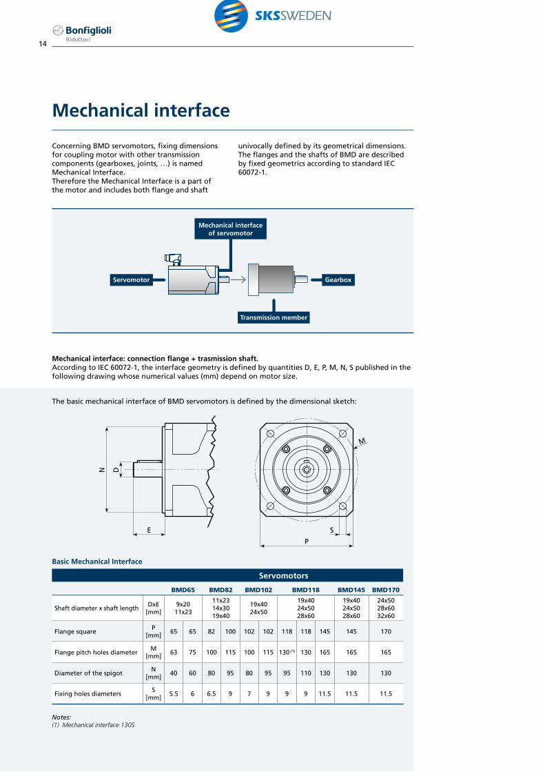
Mechanical interface
Concerning BMD servomotors, fixing dimensions for coupling motor with other transmission components (gearboxes, joints, …) is named Mechanical Interface.Therefore the Mechanical Interface is a part of the motor and includes both flange and shaft
univocally defined by its geometrical dimensions.The flanges and the shafts of BMD are described by fixed geometrics according to standard IEC 60072-1.
Mechanical interface: connection flange + trasmission shaft. According to IEC 60072-1, the interface geometry is defined by quantities D, E, P, M, N, S published in the following drawing whose numerical values (mm) depend on motor size.
GearboxServomotor
Mechanical interfaceof servomotor
Transmission member
M
P
SE
DN
The basic mechanical interface of BMD servomotors is defined by the dimensional sketch:
Basic Mechanical Interface
Servomotors
BMD65 BMD82 BMD102 BMD118 BMD145 BMD170
Shaft diameter x shaft lengthDxE
[mm]9x2011x23
11x2314x3019x40
19x4024x50
19x4024x5028x60
19x4024x5028x60
24x5028x6032x60
Flange squareP
[mm]65 65 82 100 102 102 118 118 145 145 170
Flange pitch holes diameterM
[mm]63 75 100 115 100 115 130 (1) 130 165 165 165
Diameter of the spigotN
[mm]40 60 80 95 80 95 95 110 130 130 130
Fixing holes diametersS
[mm]5.5 6 6.5 9 7 9 9 9 11.5 11.5 11.5
Notes:(1) Mechanical interface 130S

15
Mechanical tolerances
Dimensions and tolerances of shaft extension, key and flange are in accordance with IEC 60072-1. Shaft extension features an axial threaded hole in accordance with UNI 3221, DIN 332.Tolerances for the different parts are reported in the table.
Component Dimensions Tolerance
Shaft end D [mm]Ø 9 - 28 j6
Ø 32 k6
Key F [mm] h9
Flange N [mm] Ø < 250 j6
Shaft loads
The loads in the following tables have been calculated using ISO 281 calculation L10h (20.000h). The loads and speeds used are considered to be constant throughout the life of the bearing. The radial load FR is applied to the half shaft end length.
FA
FR
Maximum radial load FR [N]
Size Speed [min-1]
[Nm] 1600 3000 4500 5500 6000
BMD 650.85 300 240 210 200 1901.7 330 270 230 220 2102.2 350 280 250 230 220
BMD 823.2 580 470 410 390 3704.4 610 500 430 410 390
BMD 1027.2 750 610 530 500 4809.6 800 650 570 530 520
BMD 11810.2 860 700 610 570 55014 910 740 650 600 590
BMD 14516.8 1400 1150 1000 940 91022 1500 1200 1050 980 960
BMD 17034 900 730 640
-45 1500 1200 1050
Maximum axial load FA [N]
Size Speed [min-1]
[Nm] 1600 3000 4500 5500 6000
BMD 650.85 59 48 42 39 381.7 65 53 46 43 422.2 69 56 49 46 44
BMD 823.2 115 94 82 77 754.4 120 100 85 81 79
BMD 1027.2 150 120 105 100 959.6 160 130 110 105 100
BMD 11810.2 170 139 121 115 11014 180 145 130 120 115
BMD 14516.8 280 230 200 185 18022 295 240 210 195 190
BMD 17034 180 145 125
-45 295 240 210

16
Torque-speed characteristic
The permissible operating range of a brushless servomotor is limited by thermal, mechanical, and electromagnetic limits.
The thermal limit is dependent on the thermal class of the insulation system (F). To adhere to the temperature limits, the torque must be reduced as the speed increases, starting from stall torque M0. The maximum permissible torque is then dependent on the operation mode. The characteristic curves are assigned for continuous duty S1 and intermittent periodic duty (S3-20%, S3-50%). A transient, high overload capacity up to Mmax is provided.
The speed range is limited by the maximum mechanical speed and the voltage limit. The voltage limit is usually lower than the mechanical limit. The voltage limiting characteristic curve is determined by the motor nominal speed. The
characteristic curves for each nominal speed are reported in the same diagram. For drive sizing convenience, it is preferable to select the motor whose voltage limit curve does not lie too far above the maximum speed required for the application.
Therefore, the performance characteristics of a brushless motor are described by a torque and speed operating area. The continuous duty zone is bordered by the maximum continuous torque curve up to the intersection with the voltage limit curve. Continuous duty in the area above the S1 characteristic curve is not thermally permitted for the motor. The intermittent periodic duty zone is bordered by the peak torque line and the voltage limit curve.
Torq
ue
[Nm
]
Speed [min-1]
S3 20%
S3 50%
S1 Mn1
Mn2
Mmax
M0
00 nn1 nn2
Continuous Duty
Intermittent Periodic Duty
Voltage limit curve formotor with rated speed
nn1 and nn2
17
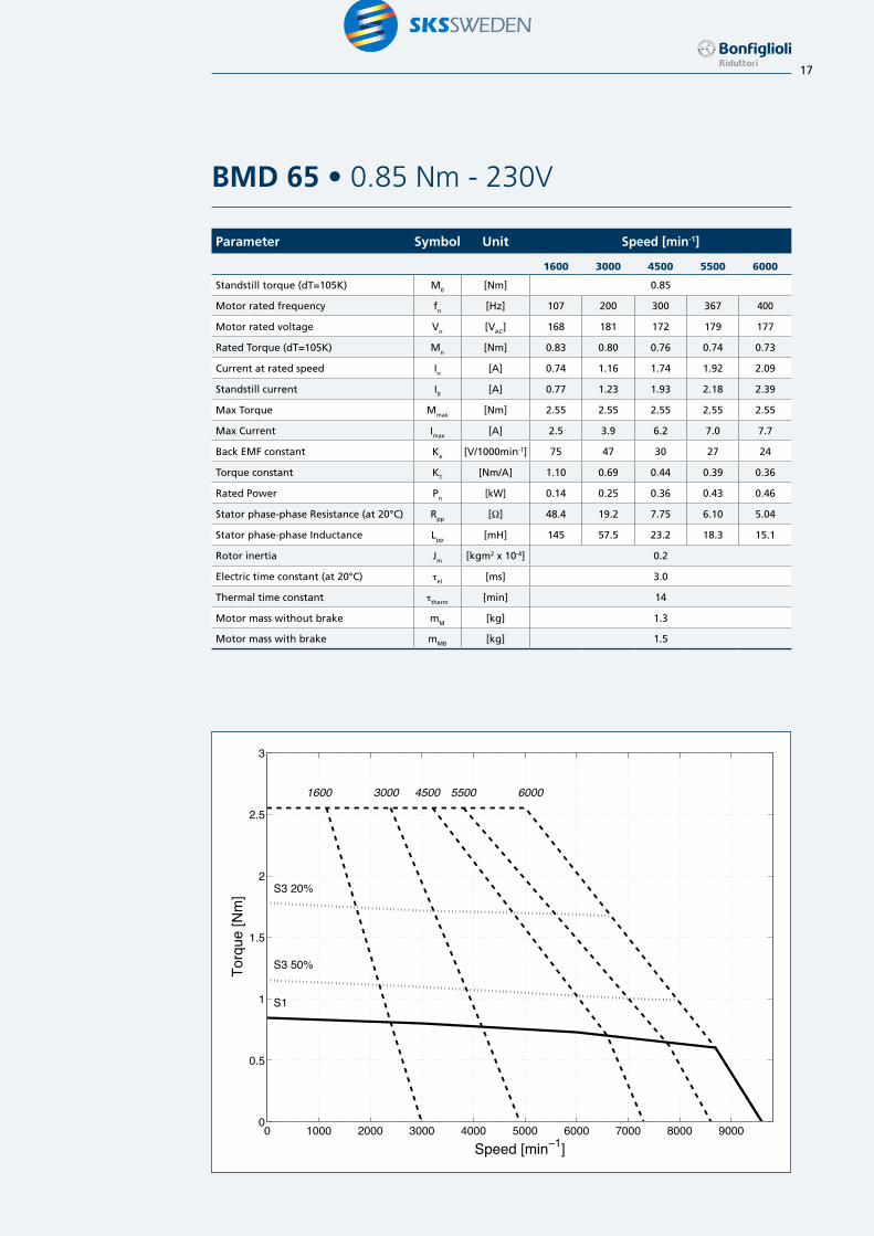
Parameter Symbol Unit Speed [min-1]
1600 3000 4500 5500 6000
Standstill torque (dT=105K) M0 [Nm] 0.85
Motor rated frequency fn [Hz] 107 200 300 367 400
Motor rated voltage Vn [VAC] 168 181 172 179 177
Rated Torque (dT=105K) Mn [Nm] 0.83 0.80 0.76 0.74 0.73
Current at rated speed In [A] 0.74 1.16 1.74 1.92 2.09
Standstill current I0 [A] 0.77 1.23 1.93 2.18 2.39
Max Torque Mmax [Nm] 2.55 2.55 2.55 2.55 2.55
Max Current Imax [A] 2.5 3.9 6.2 7.0 7.7
Back EMF constant Ke [V/1000min-1] 75 47 30 27 24
Torque constant KT [Nm/A] 1.10 0.69 0.44 0.39 0.36
Rated Power Pn [kW] 0.14 0.25 0.36 0.43 0.46
Stator phase-phase Resistance (at 20°C) Rpp [W] 48.4 19.2 7.75 6.10 5.04
Stator phase-phase Inductance Lpp [mH] 145 57.5 23.2 18.3 15.1
Rotor inertia Jm [kgm2 x 10-4] 0.2
Electric time constant (at 20°C) tel [ms] 3.0
Thermal time constant ttherm [min] 14
Motor mass without brake mM [kg] 1.3
Motor mass with brake mMB [kg] 1.5
BMD 65 • 0.85 Nm - 230V
0 1000 2000 3000 4000 5000 6000 7000 8000 90000
0.5
1
1.5
2
2.5
3
Torq
ue [N
m]
Speed [min−1]
S1
S3 50%
S3 20%
1600 3000 4500 5500 6000

18
Parameter Symbol Unit Speed [min-1]
1600 3000 4500 5500 6000
Standstill torque (dT=105K) M0 [Nm] 1.7
Motor rated frequency fn [Hz] 107 200 300 367 400
Motor rated voltage Vn [VAC] 193 180 180 174 171
Rated Torque (dT=105K) Mn [Nm] 1.65 1.60 1.52 1.48 1.45
Current at rated speed In [A] 1.25 2.30 3.2 3.9 4.2
Standstill current I0 [A] 1.26 2.34 3.4 4.2 4.7
Max Torque Mmax [Nm] 4.9 4.9 4.9 4.9 4.9
Max Current Imax [A] 4.3 8.0 11.5 14.5 15.9
Back EMF constant Ke [V/1000min-1] 89 48 33 26 24
Torque constant KT [Nm/A] 1.35 0.73 0.50 0.40 0.36
Rated Power Pn [kW] 0.28 0.50 0.72 0.85 0.91
Stator phase-phase Resistance (at 20°C) Rpp [W] 30.4 8.79 4.19 2.66 2.20
Stator phase-phase Inductance Lpp [mH] 91.9 26.6 12.6 8.0 6.6
Rotor inertia Jm [kgm2 x 10-4] 0.4
Electric time constant (at 20°C) tel [ms] 3.0
Thermal time constant ttherm [min] 20
Motor mass without brake mM [kg] 1.9
Motor mass with brake mMB [kg] 2.1
BMD 65 • 1.7 Nm - 230V
0 1000 2000 3000 4000 5000 6000 7000 8000 90000
0.5
1
1.5
2
2.5
3
3.5
4
4.5
5
5.5
Torq
ue [N
m]
Speed [min−1]
S1
S3 50%
S3 20%
1600 3000 4500 5500 6000

19
Parameter Symbol Unit Speed [min-1]
1600 3000 4500 5500 6000
Standstill torque (dT=105K) M0 [Nm] 2.2
Motor rated frequency fn [Hz] 107 200 300 367 400
Motor rated voltage Vn [VAC] 179 180 191 192 190
Rated Torque (dT=105K) Mn [Nm] 2.12 2.05 1.95 1.85 1.80
Current at rated speed In [A] 1.65 2.78 3.6 4.1 4.4
Standstill current I0 [A] 1.70 2.96 4.1 4.9 5.4
Max Torque Mmax [Nm] 6.2 6.2 6.2 6.2 6.2
Max Current Imax [A] 5.4 9.4 12.9 15.6 17.1
Back EMF constant Ke [V/1000min-1] 90 52 38 31 28
Torque constant KT [Nm/A] 1.29 0.74 0.54 0.45 0.41
Rated Power Pn [kW] 0.36 0.64 0.92 1.07 1.13
Stator phase-phase Resistance (at 20°C) Rpp [W] 18.8 6.21 3.27 2.26 1.86
Stator phase-phase Inductance Lpp [mH] 56.9 18.8 9.9 6.8 5.6
Rotor inertia Jm [kgm2 x 10-4] 0.6
Electric time constant (at 20°C) tel [ms] 3.0
Thermal time constant ttherm [min] 26
Motor mass without brake mM [kg] 2.6
Motor mass with brake mMB [kg] 2.8
BMD 65 • 2.2 Nm - 230V
0 1000 2000 3000 4000 5000 6000 7000 8000 90000
1
2
3
4
5
6
7
Torq
ue [N
m]
Speed [min−1]
S1
S3 50%
S3 20%
1600 3000 4500 5500 6000

20
Parameter Symbol Unit Speed [min-1]
1600 3000 4500 5500 6000
Standstill torque (dT=105K) M0 [Nm] 3.2
Motor rated frequency fn [Hz] 107 200 300 367 400
Motor rated voltage Vn [VAC] 191 181 200 176 176
Rated Torque (dT=105K) Mn [Nm] 3.15 3 2.8 2.6 2.5
Current at rated speed In [A] 2.37 4.3 5.3 7.0 7.6
Standstill current I0 [A] 2.41 4.5 6.0 8.3 9.0
Max Torque Mmax [Nm] 8.5 8.5 8.5 8.5 8.5
Max Current Imax [A] 8.3 15.5 20.6 28.4 31
Back EMF constant Ke [V/1000min-1] 92 49 37 27 24
Torque constant KT [Nm/A] 1.33 0.71 0.53 0.39 0.35
Rated Power Pn [kW] 0.53 0.94 1.32 1.50 1.57
Stator phase-phase Resistance (at 20°C) Rpp [W] 11.3 3.23 1.81 0.96 0.81
Stator phase-phase Inductance Lpp [mH] 64.2 18.3 10.3 5.4 4.6
Rotor inertia Jm [kgm2 x 10-4] 1.4
Electric time constant (at 20°C) tel [ms] 5.7
Thermal time constant ttherm [min] 26
Motor mass without brake mM [kg] 3.5
Motor mass with brake mMB [kg] 4.1
BMD 82 • 3.2 Nm - 230V
0 1000 2000 3000 4000 5000 6000 7000 80000
1
2
3
4
5
6
7
8
9
Torq
ue [N
m]
Speed [min−1]
S1
S3 50%
S3 20%
1600 3000 4500 5500 6000
21
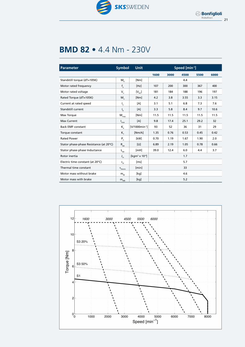
Parameter Symbol Unit Speed [min-1]
1600 3000 4500 5500 6000
Standstill torque (dT=105K) M0 [Nm] 4.4
Motor rated frequency fn [Hz] 107 200 300 367 400
Motor rated voltage Vn [VAC] 181 184 188 196 197
Rated Torque (dT=105K) Mn [Nm] 4.2 3.8 3.55 3.3 3.15
Current at rated speed In [A] 3.1 5.1 6.8 7.3 7.6
Standstill current I0 [A] 3.3 5.8 8.4 9.7 10.6
Max Torque Mmax [Nm] 11.5 11.5 11.5 11.5 11.5
Max Current Imax [A] 9.8 17.4 25.1 29.2 32
Back EMF constant Ke [V/1000min-1] 93 52 36 31 29
Torque constant KT [Nm/A] 1.35 0.76 0.53 0.45 0.42
Rated Power Pn [kW] 0.70 1.19 1.67 1.90 2.0
Stator phase-phase Resistance (at 20°C) Rpp [W] 6.89 2.19 1.05 0.78 0.66
Stator phase-phase Inductance Lpp [mH] 39.0 12.4 6.0 4.4 3.7
Rotor inertia Jm [kgm2 x 10-4] 1.7
Electric time constant (at 20°C) tel [ms] 5.7
Thermal time constant ttherm [min] 33
Motor mass without brake mM [kg] 4.6
Motor mass with brake mMB [kg] 5.2
BMD 82 • 4.4 Nm - 230V
0 1000 2000 3000 4000 5000 6000 7000 80000
2
4
6
8
10
12
Torq
ue [N
m]
Speed [min−1]
S1
S3 50%
S3 20%
1600 3000 4500 5500 6000

22
BMD 102 • 7.2 Nm - 230V
0 1000 2000 3000 4000 5000 6000 7000 80000
5
10
15
20
Torq
ue [N
m]
Speed [min−1]
S1
S3 50%
S3 20%
1600 3000 4500 5500 6000
Parameter Symbol Unit Speed [min-1]
1600 3000 4500 5500 6000
Standstill torque (dT=105K) M0 [Nm] 7.2
Motor rated frequency fn [Hz] 107 200 300 367 400
Motor rated voltage Vn [VAC] 187 177 182 183 185
Rated Torque (dT=105K) Mn [Nm] 7 6.7 6 5.8 5.6
Current at rated speed In [A] 5.0 9.5 12.6 14.4 15.4
Standstill current I0 [A] 5.0 9.7 13.9 16.9 18.2
Max Torque Mmax [Nm] 21 21 21 21 21
Max Current Imax [A] 18.3 35 51 61 66
Back EMF constant Ke [V/1000min-1] 94 49 34 28 26
Torque constant KT [Nm/A] 1.43 0.75 0.52 0.43 0.40
Rated Power Pn [kW] 1.17 2.10 2.83 3.3 3.5
Stator phase-phase Resistance (at 20°C) Rpp [W] 3.02 0.82 0.40 0.27 0.23
Stator phase-phase Inductance Lpp [mH] 25.4 6.9 3.3 2.3 1.9
Rotor inertia Jm [kgm2 x 10-4] 3.4
Electric time constant (at 20°C) tel [ms] 8.4
Thermal time constant ttherm [min] 31
Motor mass without brake mM [kg] 5.8
Motor mass with brake mMB [kg] 7

23
Parameter Symbol Unit Speed [min-1]
1600 3000 4500 5500 6000
Standstill torque (dT=105K) M0 [Nm] 9.6
Motor rated frequency fn [Hz] 107 200 300 367 400
Motor rated voltage Vn [VAC] 183 184 187 192 190
Rated Torque (dT=105K) Mn [Nm] 9.2 8.5 7.7 6.9 6.5
Current at rated speed In [A] 6.0 10.2 13.5 14.3 14.8
Standstill current I0 [A] 6.3 11.5 16.8 19.8 21.8
Max Torque Mmax [Nm] 28 28 28 28 28
Max Current Imax [A] 20.4 37 54 64 70
Back EMF constant Ke [V/1000min-1] 102 56 38 33 30
Torque constant KT [Nm/A] 1.52 0.84 0.57 0.48 0.44
Rated Power Pn [kW] 1.54 2.7 3.6 4.0 4.1
Stator phase-phase Resistance (at 20°C) Rpp [W] 2.24 0.68 0.32 0.23 0.19
Stator phase-phase Inductance Lpp [mH] 18.8 5.7 2.7 1.9 1.6
Rotor inertia Jm [kgm2 x 10-4] 4.7
Electric time constant (at 20°C) tel [ms] 8.4
Thermal time constant ttherm [min] 38
Motor mass without brake mM [kg] 7.4
Motor mass with brake mMB [kg] 8.6
BMD 102 • 9.6 Nm - 230V
0 1000 2000 3000 4000 5000 6000 7000 80000
5
10
15
20
25
30
Torq
ue [N
m]
Speed [min−1]
S1
S3 50%
S3 20%
1600 3000 4500 5500 6000

24
Parameter Symbol Unit Speed [min-1]
1600 3000 4500 5500
Standstill torque (dT=105K) M0 [Nm] 10.2
Motor rated frequency fn [Hz] 107 200 300 367
Motor rated voltage Vn [VAC] 184 178 174 196
Rated Torque (dT=105K) Mn [Nm] 10 9.5 8.5 8
Current at rated speed In [A] 7.2 13.5 18.3 17.4
Standstill current I0 [A] 7.2 13.7 20.8 22.6
Max Torque Mmax [Nm] 30 30 30 30
Max Current Imax [A] 25.3 48 73 79
Back EMF constant Ke [V/1000min-1] 95 50 33.1 30.4
Torque constant KT [Nm/A] 1.41 0.75 0.49 0.45
Rated Power Pn [kW] 1.7 3.0 4.0 4.6
Stator phase-phase Resistance (at 20°C) Rpp [W] 1.56 0.43 0.19 0.16
Stator phase-phase Inductance Lpp [mH] 20.5 5.7 2.5 2.1
Rotor inertia Jm [kgm2 x 10-4] 7.8
Electric time constant (at 20°C) tel [ms] 13
Thermal time constant ttherm [min] 34
Motor mass without brake mM [kg] 9.7
Motor mass with brake mMB [kg] 11.9
BMD 118 • 10.2 Nm - 230V
0 1000 2000 3000 4000 5000 6000 70000
5
10
15
20
25
30
Torq
ue [N
m]
Speed [min−1]
S1
S3 50%
S3 20%
1600 3000 4500 5500

25
Parameter Symbol Unit Speed [min-1]
1600 3000
Standstill torque (dT=105K) M0 [Nm] 14.0
Motor rated frequency fn [Hz] 107 200
Motor rated voltage Vn [VAC] 184 192
Rated Torque (dT=105K) Mn [Nm] 13.3 12.2
Current at rated speed In [A] 8.6 14.0
Standstill current I0 [A] 9.2 16.3
Max Torque Mmax [Nm] 39 39
Max Current Imax [A] 30 53
Back EMF constant Ke [V/1000min-1] 104 59
Torque constant KT [Nm/A] 1.51 0.86
Rated Power Pn [kW] 2.2 3.8
Stator phase-phase Resistance (at 20°C) Rpp [W] 1.17 0.37
Stator phase-phase Inductance Lpp [mH] 15.4 4.9
Rotor inertia Jm [kgm2 x 10-4] 9.9
Electric time constant (at 20°C) tel [ms] 13
Thermal time constant ttherm [min] 42
Motor mass without brake mM [kg] 11.7
Motor mass with brake mMB [kg] 12.9
BMD 118 • 14 Nm - 230V
0 500 1000 1500 2000 2500 3000 3500 4000 45000
5
10
15
20
25
30
35
40
Torq
ue [N
m]
Speed [min−1]
S1
S3 50%
S3 20%
1600 3000

26
Parameter Symbol Unit Speed [min-1]
1600 3000
Standstill torque (dT=105K) M0 [Nm] 16.8
Motor rated frequency fn [Hz] 107 200
Motor rated voltage Vn [VAC] 180 176
Rated Torque (dT=105K) Mn [Nm] 16.5 16
Current at rated speed In [A] 11.9 21.9
Standstill current I0 [A] 12.1 22.8
Max Torque Mmax [Nm] 46 46
Max Current Imax [A] 46 88
Back EMF constant Ke [V/1000min-1] 89 47
Torque constant KT [Nm/A] 1.39 0.74
Rated Power Pn [kW] 2.76 5.0
Stator phase-phase Resistance (at 20°C) Rpp [W] 0.84 0.24
Stator phase-phase Inductance Lpp [mH] 13.3 3.8
Rotor inertia Jm [kgm2 x 10-4] 12.8
Electric time constant (at 20°C) tel [ms] 16
Thermal time constant ttherm [min] 36
Motor mass without brake mM [kg] 15.2
Motor mass with brake mMB [kg] 17.8
BMD 145 • 16.8 Nm - 230V
0 500 1000 1500 2000 2500 3000 3500 4000 4500 50000
5
10
15
20
25
30
35
40
45
50
Torq
ue [N
m]
Speed [min−1]
S1
S3 50%
S3 20%
1600 3000

27
Parameter Symbol Unit Speed [min-1]
1600 3000
Standstill torque (dT=105K) M0 [Nm] 22.0
Motor rated frequency fn [Hz] 107 200
Motor rated voltage Vn [VAC] 185 202
Rated Torque (dT=105K) Mn [Nm] 20.7 19.2
Current at rated speed In [A] 14.5 22.9
Standstill current I0 [A] 15.4 26.5
Max Torque Mmax [Nm] 59 59
Max Current Imax [A] 51 87
Back EMF constant Ke [V/1000min-1] 102 60
Torque constant KT [Nm/A] 1.42 0.83
Rated Power Pn [kW] 3.5 6.0
Stator phase-phase Resistance (at 20°C) Rpp [W] 0.67 0.23
Stator phase-phase Inductance Lpp [mH] 10.6 3.6
Rotor inertia Jm [kgm2 x 10-4] 17.6
Electric time constant (at 20°C) tel [ms] 16
Thermal time constant ttherm [min] 47
Motor mass without brake mM [kg] 18.2
Motor mass with brake mMB [kg] 20.8
BMD 145 • 22 Nm - 230V
0 500 1000 1500 2000 2500 3000 3500 4000 45000
10
20
30
40
50
60
Torq
ue [N
m]
Speed [min−1]
S1
S3 50%
S3 20%
1600 3000

28
Parameter Symbol Unit Speed [min-1]
1600 3000
Standstill torque (dT=105K) M0 [Nm] 34.0
Motor rated frequency fn [Hz] 107 200
Motor rated voltage Vn [VAC] 181 182
Rated Torque (dT=105K) Mn [Nm] 31 27.5
Current at rated speed In [A] 19.7 32.2
Standstill current I0 [A] 21.8 40.4
Max Torque Mmax [Nm] 90 90
Max Current Imax [A] 66 121
Back EMF constant Ke [V/1000min-1] 99 54
Torque constant KT [Nm/A] 1.56 0.84
Rated Power Pn [kW] 5.2 8.6
Stator phase-phase Resistance (at 20°C) Rpp [W] 0.30 0.09
Stator phase-phase Inductance Lpp [mH] 5.8 1.7
Rotor inertia Jm [kgm2 x 10-4] 28.2
Electric time constant (at 20°C) tel [ms] 20
Thermal time constant ttherm [min] 50
Motor mass without brake mM [kg] 25
Motor mass with brake mMB [kg] 29.5
BMD 170 • 34 Nm - 230V
0 500 1000 1500 2000 2500 3000 3500 4000 45000
10
20
30
40
50
60
70
80
90
Torq
ue [N
m]
Speed [min−1]
S1
S3 50%
S3 20%
1600 3000

29
Parameter Symbol Unit Speed [min-1]
3000 4500 5500 6000
Standstill torque (dT=105K) M0 [Nm] 0.85
Motor rated frequency fn [Hz] 200 300 367 400
Motor rated voltage Vn [VAC] 295 331 318 306
Rated Torque (dT=105K) Mn [Nm] 0.80 0.76 0.74 0.73
Current at rated speed In [A] 0.72 0.88 1.08 1.21
Standstill current I0 [A] 0.76 0.98 1.23 1.38
Max Torque Mmax [Nm] 2.55 2.55 2.55 2.55
Max Current Imax [A] 2.43 3.1 3.9 4.4
Back EMF constant Ke [V/1000min-1] 76 59 47 42
Torque constant KT [Nm/A] 1.12 0.87 0.69 0.62
Rated Power Pn [kW] 0.25 0.36 0.43 0.46
Stator phase-phase Resistance (at 20°C) Rpp [W] 50.0 30.3 19.2 15.1
Stator phase-phase Inductance Lpp [mH] 150 90.7 57.5 45.2
Rotor inertia Jm [kgm2 x 10-4] 0.2
Electric time constant (at 20°C) tel [ms] 3.0
Thermal time constant ttherm [min] 14
Motor mass without brake mM [kg] 1.3
Motor mass with brake mMB [kg] 1.5
BMD 65 • 0.85 Nm - 400V
0 1000 2000 3000 4000 5000 6000 7000 8000 90000
0.5
1
1.5
2
2.5
3
Torq
ue [N
m]
Speed [min−1]
S1
S3 50%
S3 20%
3000 4500 5500 6000

30
Parameter Symbol Unit Speed [min-1]
1600 3000 4500 5500 6000
Standstill torque (dT=105K) M0 [Nm] 1.7
Motor rated frequency fn [Hz] 107 200 300 367 400
Motor rated voltage Vn [VAC] 336 311 308 316 300
Rated Torque (dT=105K) Mn [Nm] 1.65 1.60 1.52 1.48 1.45
Current at rated speed In [A] 0.72 1.33 1.85 2.14 2.43
Standstill current I0 [A] 0.72 1.35 1.98 2.34 2.68
Max Torque Mmax [Nm] 4.9 4.9 4.9 4.9 4.9
Max Current Imax [A] 2.46 4.6 6.7 8.0 9.1
Back EMF constant Ke [V/1000min-1] 155 83 57 48 42
Torque constant KT [Nm/A] 2.36 1.26 0.86 0.73 0.63
Rated Power Pn [kW] 0.28 0.50 0.72 0.85 0.91
Stator phase-phase Resistance (at 20°C) Rpp [W] 92.3 26.3 12.2 8.79 6.65
Stator phase-phase Inductance Lpp [mH] 279 79.5 37.0 26.6 20.1
Rotor inertia Jm [kgm2 x 10-4] 0.4
Electric time constant (at 20°C) tel [ms] 3.0
Thermal time constant ttherm [min] 20
Motor mass without brake mM [kg] 1.9
Motor mass with brake mMB [kg] 2.1
BMD 65 • 1.7 Nm - 400V
0 1000 2000 3000 4000 5000 6000 7000 8000 90000
0.5
1
1.5
2
2.5
3
3.5
4
4.5
5
5.5
Torq
ue [N
m]
Speed [min−1]
S1
S3 50%
S3 20%
1600 3000 4500 5500 6000

31
Parameter Symbol Unit Speed [min-1]
1600 3000 4500 5500 6000
Standstill torque (dT=105K) M0 [Nm] 2.2
Motor rated frequency fn [Hz] 107 200 300 367 400
Motor rated voltage Vn [VAC] 285 314 314 328 313
Rated Torque (dT=105K) Mn [Nm] 2.12 2.05 1.95 1.85 1.80
Current at rated speed In [A] 1.04 1.60 2.20 2.41 2.68
Standstill current I0 [A] 1.07 1.70 2.48 2.88 3.27
Max Torque Mmax [Nm] 6.2 6.2 6.2 6.2 6.2
Max Current Imax [A] 3.4 5.4 7.9 9.1 10.4
Back EMF constant Ke [V/1000min-1] 143 90 62 53 47
Torque constant KT [Nm/A] 2.06 1.29 0.89 0.76 0.67
Rated Power Pn [kW] 0.36 0.64 0.92 1.07 1.13
Stator phase-phase Resistance (at 20°C) Rpp [W] 47.6 18.8 8.82 6.56 5.08
Stator phase-phase Inductance Lpp [mH] 144 56.9 26.7 19.8 15.4
Rotor inertia Jm [kgm2 x 10-4] 0.6
Electric time constant (at 20°C) tel [ms] 3.0
Thermal time constant ttherm [min] 26
Motor mass without brake mM [kg] 2.6
Motor mass with brake mMB [kg] 2.8
BMD 65 • 2.2 Nm - 400V
0 1000 2000 3000 4000 5000 6000 7000 8000 90000
1
2
3
4
5
6
7
Torq
ue [N
m]
Speed [min−1]
S1
S3 50%
S3 20%
1600 3000 4500 5500 6000

32
Parameter Symbol Unit Speed [min-1]
1600 3000 4500 5500 6000
Standstill torque (dT=105K) M0 [Nm] 3.2
Motor rated frequency fn [Hz] 107 200 300 367 400
Motor rated voltage Vn [VAC] 332 315 312 323 308
Rated Torque (dT=105K) Mn [Nm] 3.15 3 2.8 2.6 2.5
Current at rated speed In [A] 1.36 2.50 3.4 3.8 4.3
Standstill current I0 [A] 1.39 2.60 3.9 4.5 5.2
Max Torque Mmax [Nm] 8.5 8.5 8.5 8.5 8.5
Max Current Imax [A] 4.7 8.9 13.2 15.5 17.7
Back EMF constant Ke [V/1000min-1] 159 85 57 49 43
Torque constant KT [Nm/A] 2.31 1.23 0.83 0.71 0.62
Rated Power Pn [kW] 0.53 0.94 1.32 1.50 1.57
Stator phase-phase Resistance (at 20°C) Rpp [W] 34.3 9.75 4.42 3.23 2.47
Stator phase-phase Inductance Lpp [mH] 194 55.2 25.0 18.3 14.0
Rotor inertia Jm [kgm2 x 10-4] 1.4
Electric time constant (at 20°C) tel [ms] 5.7
Thermal time constant ttherm [min] 26
Motor mass without brake mM [kg] 3.5
Motor mass with brake mMB [kg] 4.1
BMD 82 • 3.2 Nm - 400V
0 1000 2000 3000 4000 5000 6000 7000 80000
1
2
3
4
5
6
7
8
9
Torq
ue [N
m]
Speed [min−1]
S1
S3 50%
S3 20%
1600 3000 4500 5500 6000

33
Parameter Symbol Unit Speed [min-1]
1600 3000 4500 5500 6000
Standstill torque (dT=105K) M0 [Nm] 4.4
Motor rated frequency fn [Hz] 107 200 300 367 400
Motor rated voltage Vn [VAC] 315 323 328 335 335
Rated Torque (dT=105K) Mn [Nm] 4.2 3.8 3.55 3.3 3.15
Current at rated speed In [A] 1.76 2.90 3.9 4.3 4.5
Standstill current I0 [A] 1.88 3.3 4.8 5.7 6.2
Max Torque Mmax [Nm] 11.5 11.5 11.5 11.5 11.5
Max Current Imax [A] 5.6 9.9 14.4 17.1 18.6
Back EMF constant Ke [V/1000min-1] 161 92 63 53 49
Torque constant KT [Nm/A] 2.34 1.33 0.92 0.77 0.71
Rated Power Pn [kW] 0.70 1.19 1.67 1.90 2.0
Stator phase-phase Resistance (at 20°C) Rpp [W] 20.8 6.77 3.21 2.26 1.92
Stator phase-phase Inductance Lpp [mH] 118 38.3 18.1 12.8 10.8
Rotor inertia Jm [kgm2 x 10-4] 1.7
Electric time constant (at 20°C) tel [ms] 5.7
Thermal time constant ttherm [min] 33
Motor mass without brake mM [kg] 4.6
Motor mass with brake mMB [kg] 5.2
BMD 82 • 4.4 Nm - 400V
0 1000 2000 3000 4000 5000 6000 7000 80000
2
4
6
8
10
12
Torq
ue [N
m]
Speed [min−1]
S1
S3 50%
S3 20%
1600 3000 4500 5500 6000

34
Parameter Symbol Unit Speed [min-1]
1600 3000 4500 5500 6000
Standstill torque (dT=105K) M0 [Nm] 7.2
Motor rated frequency fn [Hz] 107 200 300 367 400
Motor rated voltage Vn [VAC] 320 311 305 320 305
Rated Torque (dT=105K) Mn [Nm] 7 6.7 6 5.8 5.6
Current at rated speed In [A] 2.92 5.4 7.5 8.2 9.3
Standstill current I0 [A] 2.94 5.5 8.3 9.7 11.0
Max Torque Mmax [Nm] 21 21 21 21 21
Max Current Imax [A] 10.7 20.0 30 35 40
Back EMF constant Ke [V/1000min-1] 161 86 57 49 43
Torque constant KT [Nm/A] 2.45 1.31 0.87 0.75 0.65
Rated Power Pn [kW] 1.17 2.10 2.83 3.3 3.5
Stator phase-phase Resistance (at 20°C) Rpp [W] 8.87 2.53 1.11 0.82 0.63
Stator phase-phase Inductance Lpp [mH] 74.7 21.3 9.4 6.9 5.3
Rotor inertia Jm [kgm2 x 10-4] 3.7
Electric time constant (at 20°C) tel [ms] 1.4
Thermal time constant ttherm [min] 31
Motor mass without brake mM [kg] 5.8
Motor mass with brake mMB [kg] 7
BMD 102 • 7.2 Nm - 400V
0 1000 2000 3000 4000 5000 6000 7000 80000
5
10
15
20
Torq
ue [N
m]
Speed [min−1]
S1
S3 50%
S3 20%
1600 3000 4500 5500 6000

35
Parameter Symbol Unit Speed [min-1]
1600 3000 4500 5500 6000
Standstill torque (dT=105K) M0 [Nm] 9.6
Motor rated frequency fn [Hz] 107 200 300 367 400
Motor rated voltage Vn [VAC] 318 324 323 332 333
Rated Torque (dT=105K) Mn [Nm] 9.2 8.5 7.7 6.9 6.5
Current at rated speed In [A] 3.4 5.8 7.8 8.3 8.4
Standstill current I0 [A] 3.6 6.5 9.7 11.5 12.4
Max Torque Mmax [Nm] 28 28 28 28 28
Max Current Imax [A] 11.7 21.0 31 37 40
Back EMF constant Ke [V/1000min-1] 177 99 66 56 52
Torque constant KT [Nm/A] 2.65 1.48 0.99 0.84 0.77
Rated Power Pn [kW] 1.54 2.7 3.6 4.0 4.1
Stator phase-phase Resistance (at 20°C) Rpp [W] 6.77 2.11 0.95 0.68 0.58
Stator phase-phase Inductance Lpp [mH] 56.8 17.7 8.0 5.7 4.8
Rotor inertia Jm [kgm2 x 10-4] 4.7
Electric time constant (at 20°C) tel [ms] 8.4
Thermal time constant ttherm [min] 38
Motor mass without brake mM [kg] 7.4
Motor mass with brake mMB [kg] 8.4
BMD 102 • 9.6 Nm - 400V
0 1000 2000 3000 4000 5000 6000 7000 80000
5
10
15
20
25
30
Torq
ue [N
m]
Speed [min−1]
S1
S3 50%
S3 20%
1600 3000 4500 5500 6000
36
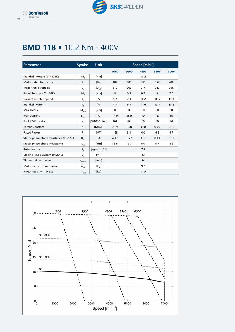
Parameter Symbol Unit Speed [min-1]
1600 3000 4500 5500 6000
Standstill torque (dT=105K) M0 [Nm] 10.2
Motor rated frequency fn [Hz] 107 200 300 367 400
Motor rated voltage Vn [VAC] 312 305 314 323 306
Rated Torque (dT=105K) Mn [Nm] 10 9.5 8.5 8 7.5
Current at rated speed In [A] 4.2 7.9 10.2 10.5 11.4
Standstill current I0 [A] 4.3 8.0 11.6 13.7 15.8
Max Torque Mmax [Nm] 30 30 30 30 30
Max Current Imax [A] 14.9 28.0 40 48 55
Back EMF constant Ke [V/1000min-1] 161 86 60 50 44
Torque constant KT [Nm/A] 2.39 1.28 0.88 0.75 0.65
Rated Power Pn [kW] 1.68 3.0 4.0 4.6 4.7
Stator phase-phase Resistance (at 20°C) Rpp [W] 4.47 1.27 0.61 0.43 0.33
Stator phase-phase Inductance Lpp [mH] 58.8 16.7 8.0 5.7 4.3
Rotor inertia Jm [kgm2 x 10-4] 7.8
Electric time constant (at 20°C) tel [ms] 13
Thermal time constant ttherm [min] 34
Motor mass without brake mM [kg] 9.7
Motor mass with brake mMB [kg] 11.9
BMD 118 • 10.2 Nm - 400V
0 1000 2000 3000 4000 5000 6000 70000
5
10
15
20
25
30
Torq
ue [N
m]
Speed [min−1]
S1
S3 50%
S3 20%
1600 3000 4500 5500 6000

37
Parameter Symbol Unit Speed [min-1]
1600 3000 4500 5500 6000
Standstill torque (dT=105K) M0 [Nm] 14.0
Motor rated frequency fn [Hz] 107 200 300 367 400
Motor rated voltage Vn [VAC] 323 320 325 335 329
Rated Torque (dT=105K) Mn [Nm] 13.3 12.2 10.9 9.7 9.0
Current at rated speed In [A] 4.9 8.4 10.9 11.4 11.8
Standstill current I0 [A] 5.3 9.8 14.4 16.9 18.9
Max Torque Mmax [Nm] 39 39 39 39 39
Max Current Imax [A] 17.2 32 47 55 62
Back EMF constant Ke [V/1000min-1] 182 98 67 57 51
Torque constant KT [Nm/A] 2.66 1.43 0.97 0.83 0.74
Rated Power Pn [kW] 2.2 3.8 5.0 5.3 5.3
Stator phase-phase Resistance (at 20°C) Rpp [W] 3.60 1.04 0.48 0.35 0.28
Stator phase-phase Inductance Lpp [mH] 47.4 13.7 6.3 4.6 3.7
Rotor inertia Jm [kgm2 x 10-4] 9.9
Electric time constant (at 20°C) tel [ms] 13
Thermal time constant ttherm [min] 42
Motor mass without brake mM [kg] 11.7
Motor mass with brake mMB [kg] 12.9
BMD 118 • 14 Nm - 400V
0 1000 2000 3000 4000 5000 6000 70000
5
10
15
20
25
30
35
40
Torq
ue [N
m]
Speed [min−1]
S1
S3 50%
S3 20%
1600 3000 4500 5500 6000

38
Parameter Symbol Unit Speed [min-1]
1600 3000 4500 5500 6000
Standstill torque (dT=105K) M0 [Nm] 16.8
Motor rated frequency fn [Hz] 107 200 300 367 400
Motor rated voltage Vn [VAC] 314 308 314 319 305
Rated Torque (dT=105K) Mn [Nm] 16.5 16 14 13 12.5
Current at rated speed In [A] 6.8 12.5 16.4 17.5 19
Standstill current I0 [A] 6.9 13.0 19.0 22.8 26
Max Torque Mmax [Nm] 46 46 46 46 46
Max Current Imax [A] 26.7 50 73 88 100
Back EMF constant Ke [V/1000min-1] 156 83 57 47 42
Torque constant KT [Nm/A] 2.42 1.29 0.88 0.74 0.65
Rated Power Pn [kW] 2.76 5.0 6.6 7.5 7.9
Stator phase-phase Resistance (at 20°C) Rpp [W] 2.53 0.72 0.34 0.24 0.18
Stator phase-phase Inductance Lpp [mH] 40.4 11.5 5.4 3.8 2.9
Rotor inertia Jm [kgm2 x 10-4] 12.8
Electric time constant (at 20°C) tel [ms] 16
Thermal time constant ttherm [min] 36
Motor mass without brake mM [kg] 15.2
Motor mass with brake mMB [kg] 17.8
BMD 145 • 16.8 Nm - 400V
0 1000 2000 3000 4000 5000 6000 70000
5
10
15
20
25
30
35
40
45
50
Torq
ue [N
m]
Speed [min−1]
S1
S3 50%
S3 20%
1600 3000 4500 5500 6000

39
Parameter Symbol Unit Speed [min-1]
1600 3000 4500 5500
Standstill torque (dT=105K) M0 [Nm] 22.0
Motor rated frequency fn [Hz] 107 200 300 367
Motor rated voltage Vn [VAC] 319 321 323 357
Rated Torque (dT=105K) Mn [Nm] 20.7 19.2 17 15
Current at rated speed In [A] 8.4 14.2 18.3 17.6
Standstill current I0 [A] 9.0 16.4 24.3 26.5
Max Torque Mmax [Nm] 59 59 59 59
Max Current Imax [A] 29.5 54 80 87
Back EMF constant Ke [V/1000min-1] 176 96 65 59
Torque constant KT [Nm/A] 2.45 1.34 0.90 0.83
Rated Power Pn [kW] 3.5 6.0 8.0 8.6
Stator phase-phase Resistance (at 20°C) Rpp [W] 1.97 0.59 0.27 0.23
Stator phase-phase Inductance Lpp [mH] 31.5 9.4 4.3 3.6
Rotor inertia Jm [kgm2 x 10-4] 17.6
Electric time constant (at 20°C) tel [ms] 16
Thermal time constant ttherm [min] 47
Motor mass without brake mM [kg] 18.2
Motor mass with brake mMB [kg] 20.8
BMD 145 • 22 Nm - 400V
0 1000 2000 3000 4000 5000 6000 70000
10
20
30
40
50
60
Torq
ue [N
m]
Speed [min−1]
S1
S3 50%
S3 20%
1600 3000 4500 5500

40
Parameter Symbol Unit Speed [min-1]
1600 3000
Standstill torque (dT=105K) M0 [Nm] 34.0
Motor rated frequency fn [Hz] 107 200
Motor rated voltage Vn [VAC] 319 315
Rated Torque (dT=105K) Mn [Nm] 31 27.5
Current at rated speed In [A] 11.2 18.6
Standstill current I0 [A] 12.4 23.3
Max Torque Mmax [Nm] 90 90
Max Current Imax [A] 37 70
Back EMF constant Ke [V/1000min-1] 174 93
Torque constant KT [Nm/A] 2.74 1.46
Rated Power Pn [kW] 5.2 8.6
Stator phase-phase Resistance (at 20°C) Rpp [W] 0.91 0.26
Stator phase-phase Inductance Lpp [mH] 17.9 5.1
Rotor inertia Jm [kgm2 x 10-4] 28.2
Electric time constant (at 20°C) tel [ms] 20
Thermal time constant ttherm [min] 50
Motor mass without brake mM [kg] 25
Motor mass with brake mMB [kg] 29.5
BMD 170 • 34 Nm - 400V
0 500 1000 1500 2000 2500 3000 3500 4000 4500 50000
10
20
30
40
50
60
70
80
90
Torq
ue [N
m]
Speed [min−1]
S1
S3 50%
S3 20%
1600 3000
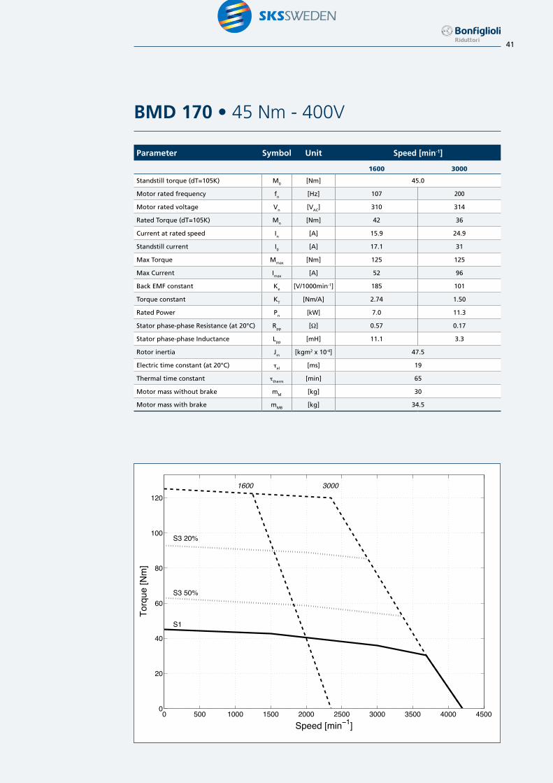
41
Parameter Symbol Unit Speed [min-1]
1600 3000
Standstill torque (dT=105K) M0 [Nm] 45.0
Motor rated frequency fn [Hz] 107 200
Motor rated voltage Vn [VAC] 310 314
Rated Torque (dT=105K) Mn [Nm] 42 36
Current at rated speed In [A] 15.9 24.9
Standstill current I0 [A] 17.1 31
Max Torque Mmax [Nm] 125 125
Max Current Imax [A] 52 96
Back EMF constant Ke [V/1000min-1] 185 101
Torque constant KT [Nm/A] 2.74 1.50
Rated Power Pn [kW] 7.0 11.3
Stator phase-phase Resistance (at 20°C) Rpp [W] 0.57 0.17
Stator phase-phase Inductance Lpp [mH] 11.1 3.3
Rotor inertia Jm [kgm2 x 10-4] 47.5
Electric time constant (at 20°C) tel [ms] 19
Thermal time constant ttherm [min] 65
Motor mass without brake mM [kg] 30
Motor mass with brake mMB [kg] 34.5
BMD 170 • 45 Nm - 400V
0 500 1000 1500 2000 2500 3000 3500 4000 45000
20
40
60
80
100
120
Torq
ue [N
m]
Speed [min−1]
S1
S3 50%
S3 20%
1600 3000

42
Type Shaft
D E DB GA(1) F(1)
659 20 M3 10.2 3
11 23 M4 12.5 4
82
11 23 M4 12.5 4
14 30 M5 16 5
19 40 M6 21.5 6
10219 40 M6 21.5 6
24 50 M8 27 8
Type Flange
M N P S T LA
6563 40 65 5.5 2.5 7
75 60 65 6 2.5 7
82
100 80 82 6.5 3 10
115 95 100 9 3 10
102100 80 102 7 3 10
115 95 102 9 3 10
Dimensions (from BMD 65 to BMD 102)
P
LB AF
AD
p
AD
S
LA
GA
LLp
LLs
V E
øDA
A
øDB
F
T
øNP
øS
øM
45°
45°
Type Motor
T0 AC LB2 LB3 LB4 LB5 LB6 LB7 ADp ADs AF LLp LLs V8 V9 V10 V11
65
0.85
65
112 143 130 130 179 179
41.5 41.5 32 96 96
89 89 138 138
1.7 135 166 153 153 202 202 112 112 161 161
2.2 161 192 179 179 228 228 138 138 187 187
823.2
82160 200 183 160 223 223
41.5 41.5 36 96 96132 132 195 195
4.4 180 220 203 180 243 243 152 152 215 215
1027.2
102180 220 203 180 243 220
41.5 41.5 39 96 96150 150 190 190
9.6 207 247 230 207 297 247 177 177 217 217
Notes:(1) Motor shaft extension without key available.LB
2 Motor length with resolver, or in sensorless version.
LB3 Motor length with resolver, or in sensorless version, and with brake or flywheel.
LB4 Motor length with encoder EnDat (ENB1, ENB2).
LB5 Motor length with encoder Hiperface (ENB3, ENB4).
LB6 Motor length with encoder EnDat (ENB1, ENB2) and with brake or flywheel
LB7 Motor length with encoder Hiperface (ENB3, ENB4) and with brake or flywheel
V8 Motor with resolver, encoder (ENB1, ENB2, ENB3, ENB4) or in sensorless version.
V9 Motor with resolver, or in sensorless version and with brake or flywheel.
V10
Motor with encoder EnDat (ENB1, ENB2) and with brake or flywheelV
11 Motor with encoder Hiperface (ENB3, ENB4) and with brake or flywheel

43
Notes:(1) Motor shaft extension without key available.(2) Mechanical interface 130S.LB
2 Motor length with resolver, or in sensorless version.
LB3 Motor length with resolver, or in sensorless version, and with brake or flywheel.
LB4 Motor length with encoder EnDat (ENB1, ENB2).
LB5 Motor length with encoder Hiperface (ENB3, ENB4).
LB6 Motor length with encoder EnDat (ENB1, ENB2) and with brake or flywheel
LB7 Motor length with encoder Hiperface (ENB3, ENB4) and with brake or flywheel
V8 Motor with resolver, encoder (ENB1, ENB2, ENB3, ENB4) or in sensorless version.
V9 Motor with resolver, or in sensorless version and with brake or flywheel.
V10
Motor with encoder EnDat (ENB1, ENB2) and with brake or flywheelV
11 Motor with encoder Hiperface (ENB3, ENB4) and with brake or flywheel
Type Motor
T0 AC LB2 LB3 LB4 LB5 LB6 LB7 ADp ADs AF LLp LLs V8 V9 V10 V11
11810.2
118210 260 235 210 285 260
41.5 41.5 96 96 96175 225 225 225
14 243 293 268 243 351 293 208 258 258 258
14516.8
145230 280 255 230 305 280
41.5 41.5 96 96 96195 245 245 245
22 265 315 290 265 375 315 230 280 280 280
17034
170265 340 303 265 378 340
41.5 41.5 140 96 96233 308 308 308
45 319 394 357 319 432 394 287 362 362 362
Type Shaft
D E DB GA(1) F(1)
118
19 40 M6 21.5 6
24 50 M8 27 8
28 60 M10 31 8
145
19 40 M6 21.5 6
24 50 M8 27 8
28 60 M10 31 8
170
24 50 M8 27 8
28 60 M10 31 8
32 60 M12 35 10
Type Flange
M N P S T LA
118
130 (2) 95 118 9 3.5 10
130 110 118 9 3.5 10
165 130 145 11.5 3.5 10
145 165 130 145 11.5 3.5 12
170 165 130 170 11.5 3.5 12
Dimensions (from BMD 118 to BMD 170)
P
LB AF
AD
p
AD
S
LA
GA
LLp
LLs
V E
øDA
A
øDB
F
T
øNP
øS
øM
45°
45°

44
Resolver datasheet
S1 S3
StatorV1
StatorV2
S2
S4
RotorVR
StatorVe
R1
R2
Stationary
StationaryRotatingStationary
Item BMD 65 BMD82 - BMD170
RES2 RES1 RES2
Poles number 2 2 2
Transformation ratio 0.5 ±5% 0.5 +15%
-5%0.5 ±5%
Input voltage [Vacrms] 7 11 5.5
Input current [mA] 65 57 61
Input frequency [kHz] 10 8 10
Phase shift 0° -11° -12°
Input impedance Zro (W) 70 + j100 75 + j185 43 + j79
Output impedance Zss (W) 175 +j275 135 + j265 62 + j112
Electrical error ±10’ ±10’ ±10’
Accuracy ripple 1’ max 1’ max 1’ max
Operating temperature -55°C ... + 155°C -55°C ... + 155°C -55°C ... + 155°C
Max Speed [min-1] 10000 20000 10000
Mass [kg] 0.065 0.28 0.28
Rotor Inertia [kgm2 x 10-6] 3.0 5.0 5.0
Feedback devices
Bonfiglioli BMD servomotor series is available with different feedback devices. Available feedbacks are resolver and optical absolute encoders, single turn or multi turn. All available feeback devices are managed by the Bonfiglioli Vectron frequency inverter of ACTIVE CUBE series. Dedicated feedback interfaces are available.
The resolver is a passive wound device consisting of a stator and rotor elements excited from an external source. It produces two output signals that correspond to the sine and cosine angle of the motor shaft.This is a robust absolute device of good accuracy, capable of withstanding high temperature and high levels of vibration. Positional information is absolute within one turn.
The optical absolute encoder uses a high precision optical disc. The high resolution performed is based on a combination of absolute information, transmitted via a serial link, and sine/cosine signals with incremental techniques. Single turn absolute encoder has an absolute positional information only within one turn.
Multi turn absolute encoder is provided of extra gear wheels that account for several shaft revolution. Therefore the output is unique for each shaft position and revolution up to available revolutions.

45
Encoder datasheet
HEIDENHAIN ENCODERS
Item BMD 65 BMD82 - BMD170
ENB1 ENB2 ENB1 ENB2
Data interface EnDat EnDat
Model ECN1113 EQN1125 ECN1313 EQN1325
Type Single turn Multi turn Single turn Multi turn
Power supply 3.6VDC ... 14VDC 3.6VDC ... 14VDC 3.6VDC ... 14VDC 3.6VDC ... 14VDC
Current consumption 85mA (5V) 105mA (5V) 85mA (5V) 105mA (5V)
Periods per revolution 512 512 2048 2048
Position per revolution 8192 (13 bits) 8192 (13 bits) 8192 (13 bits) 8192 (13 bits)
Revolutions - 4096 (12 bits) - 4096 (12 bits)
Operating temperature -40°C ... +115°C -40°C ... +115°C
Max Speed [min-1] 12000 12000
Mass [kg] 0.10 0.25
Rotor Inertia [kgm2 x 10-6] 0.40 2.60
SICK ENCODERS
Item BMD 65 BMD82 - BMD170
ENB3 ENB4 ENB3 ENB4
Data interface Hiperface Hiperface
Model SKS36 SKM36 SRS50 SRM50
Type Single turn Multi turn Single turn Multi turn
Power supply 7VDC ... 12VDC 7VDC ... 12VDC 7VDC ... 12VDC 7VDC ... 12VDC
Current consumption 60mA 60mA 80mA 80mA
Periods per revolution 128 128 1024 1024
Position per revolution 4096 (12 bits) 4096 (12 bits) 32768 (15 bit) 32768 (15 bit)
Revolutions - 4096 (12 bits) - 4096 (12 bits)
Operating temperature -30°C ... +110°C -20°C ... +110°C
Max Speed [min-1] 10000 12000
Mass [kg] 0.07 0.20
Rotor Inertia [kgm2 x 10-6] 0.45 1.00

46
PTC/KTY thermal protection
All motors in the BMD Series are equipped with an integrated PTC temperature as standard to protect the windings against overtemperatures exceeding the limit of the motor class F insulation.These sensors are in conformity to standard DIN 44081-82.Optionally a KTY sensor is available, to fit any needs for temperature feedback.The PTC temperature sensor consists of a special ceramic resistor whose ohmic value varies with the temperature of the electrical winding with which it is held on close contact. Each temperature value generates a known resistance, so that provided the resistor is fed at a constant voltage, the output current can be used to determine the corresponding temperature. If temperature
reaches an established limit, the circuit monitoring the signal trips the necessary cutout to disconnect power to the motor and prevent damage.
KTY 84-130KTY 84-130 silicon sensors are optionally available. Working temperature range: -40°C ÷ +260°C.
PTC characteristic curveaccording to DIN 44081-82
R(T) characteristiccurve of KTY 84-130.
BMD
PT
Therm/PTC Therm/PTC
A triple PTC thermistor rated to 150˚C is placed into the motor winding. The resistance curve of the PTC thermistor is in accordance with DIN 44081-82.
Lg R (log) [Ω]
RPTC
Rref
RN
Rmin
TN TRmin Tref TPTC
T
[°C]
3.0
2.0
1.0
0-100 0 100 200 300
R[kΩ]
T [°C]

47
Electromechanical holding brake
An electromagnetic holding brake is available. The brake variant can be ordered by selecting the F24 value in the brake option field.
The electromechanical brake is for use as an holding brake with motor shaft stationary. Do not use it as a dynamic brake, except for emergencies such as main supply faliure.
Data of the available brake for each motor size are summarized in the following table.When the motor is delivered without brake, the brake fitting is not possible.
The brake coil voltage supply must be 24V DC-voltage.The brake option is responsible of an increment of the motor length (see in pages 42-43).Brake leads are wired in the power connector togheter with motor leads.
Please note that the brake option is not available when the “additional inertia” option is selected.
MotorMotor stall
torqueRated brake torque 20°C
Mb
Rated brake torque 100°C
Mb
Brake voltage
Vb
Brakecurrent
Ib
Brake power 20°C
Pb
Brakeinertia
Mass
mb
Engaging time
t1
Releasetime
t2
Nm Nm Nm Vdc A W Kgm2 x10-4 kg ms ms
65
0.85
2 1.8
24
0.46 11 0.068 0.15 6 251.7
2.2
823.2
4.5 4 0.5 12 0.18 0.35 7 354.4
1027.2
9 8 0.75 18 0.54 0.7 7 409.6
11810.2
18 15 1.0 24 1.66 1.1 10 5014
14516.8
18 15 1.0 24 1.66 1.1 10 5022
17034
36 32 1.1 26 5.56 1.8 22 9045
Notet1 Time from disconnecting the current until the rated torque is attained t2 Time from connecting the current until the torque decreases
48
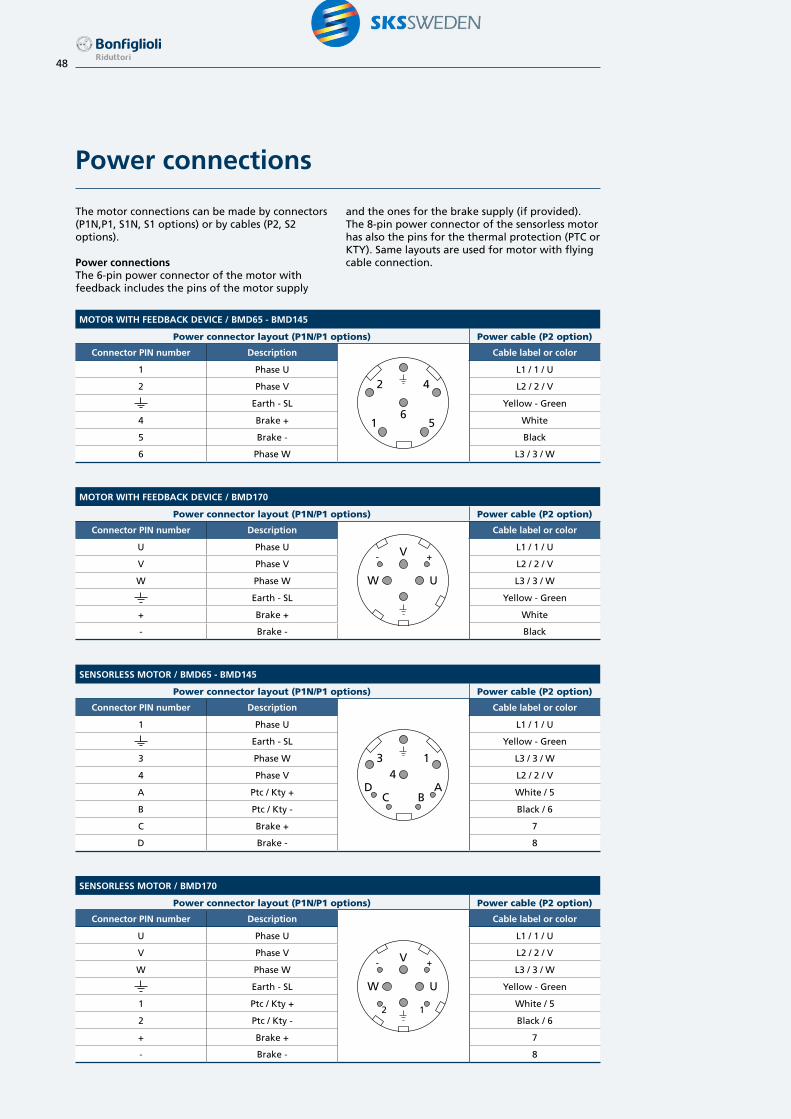
Power connections
The motor connections can be made by connectors (P1N,P1, S1N, S1 options) or by cables (P2, S2 options).
Power connectionsThe 6-pin power connector of the motor with feedback includes the pins of the motor supply
and the ones for the brake supply (if provided). The 8-pin power connector of the sensorless motor has also the pins for the thermal protection (PTC or KTY). Same layouts are used for motor with flying cable connection.
MOTOR WITH FEEDBACK DEVICE / BMD65 - BMD145
Power connector layout (P1N/P1 options) Power cable (P2 option)
Connector PIN number Description
2
1 56
4
Cable label or color
1 Phase U L1 / 1 / U
2 Phase V L2 / 2 / V
Earth - SL Yellow - Green
4 Brake + White
5 Brake - Black
6 Phase W L3 / 3 / W
SENSORLESS MOTOR / BMD65 - BMD145
Power connector layout (P1N/P1 options) Power cable (P2 option)
Connector PIN number Description
3
DC B
A4
1
Cable label or color
1 Phase U L1 / 1 / U
Earth - SL Yellow - Green
3 Phase W L3 / 3 / W
4 Phase V L2 / 2 / V
A Ptc / Kty + White / 5
B Ptc / Kty - Black / 6
C Brake + 7
D Brake - 8
MOTOR WITH FEEDBACK DEVICE / BMD170
Power connector layout (P1N/P1 options) Power cable (P2 option)
Connector PIN number Description
V
W U
- +
Cable label or color
U Phase U L1 / 1 / U
V Phase V L2 / 2 / V
W Phase W L3 / 3 / W
Earth - SL Yellow - Green
+ Brake + White
- Brake - Black
SENSORLESS MOTOR / BMD170
Power connector layout (P1N/P1 options) Power cable (P2 option)
Connector PIN number Description
V
W U
- +
2 1
Cable label or color
U Phase U L1 / 1 / U
V Phase V L2 / 2 / V
W Phase W L3 / 3 / W
Earth - SL Yellow - Green
1 Ptc / Kty + White / 5
2 Ptc / Kty - Black / 6
+ Brake + 7
- Brake - 8
49
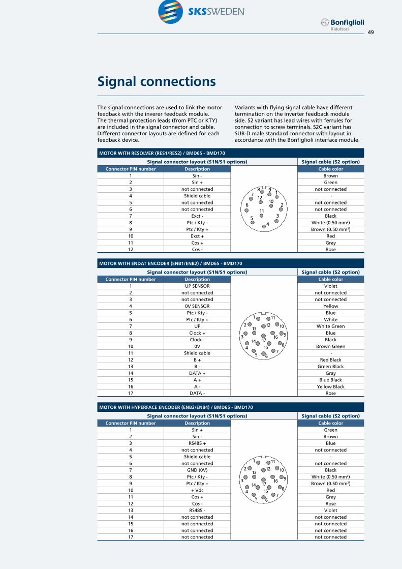
Signal connections
The signal connections are used to link the motor feedback with the inverer feedback module. The thermal protection leads (from PTC or KTY) are included in the signal connector and cable. Different connector layouts are defined for each feedback device.
Variants with flying signal cable have different termination on the inverter feedback module side. S2 variant has lead wires with ferrules for connection to screw terminals. S2C variant has SUB-D male standard connector with layout in accordance with the Bonfiglioli interface module.
MOTOR WITH RESOLVER (RES1/RES2) / BMD65 - BMD170
Signal connector layout (S1N/S1 options) Signal cable (S2 option)
Connector PIN number Description
87
12
611
5 3
4
102
91
Cable color1 Sin - Brown2 Sin + Green3 not connected not connected4 Shield cable -5 not connected not connected6 not connected not connected7 Exct - Black8 Ptc / Kty - White (0.50 mm2)9 Ptc / Kty + Brown (0.50 mm2)10 Exct + Red11 Cos + Gray12 Cos - Rose
MOTOR WITH ENDAT ENCODER (ENB1/ENB2) / BMD65 - BMD170
Signal connector layout (S1N/S1 options) Signal cable (S2 option)
Connector PIN number Description
1
2
3
4
5 67
8
9
10
11
1213
14 1716
15
Cable color1 UP SENSOR Violet2 not connected not connected3 not connected not connected4 0V SENSOR Yellow5 Ptc / Kty - Blue6 Ptc / Kty + White7 UP White Green8 Clock + Blue9 Clock - Black
10 0V Brown Green11 Shield cable -12 B + Red Black13 B - Green Black14 DATA + Gray15 A + Blue Black16 A - Yellow Black17 DATA - Rose
MOTOR WITH HYPERFACE ENCODER (ENB3/ENB4) / BMD65 - BMD170
Signal connector layout (S1N/S1 options) Signal cable (S2 option)
Connector PIN number Description
1
2
3
4
5 67
8
9
10
11
1213
14 1716
15
Cable color1 Sin + Green2 Sin - Brown3 RS485 + Blue4 not connected not connected5 Shield cable -6 not connected not connected7 GND (0V) Black8 Ptc / Kty - White (0.50 mm2)9 Ptc / Kty + Brown (0.50 mm2)10 + Vdc Red11 Cos + Gray12 Cos - Rose13 RS485 - Violet14 not connected not connected15 not connected not connected16 not connected not connected17 not connected not connected

50
Additional inertia feature
BMD Permanent Magnet AC Synchronous Motor series is provided optionally with additional inertia. The BMD motors with additional inertia have higher rotor moment of inertia in comparison with basic version.
Additional inertia is designed to be used in application with high load inertia. The increased rotor moment of inertia provides a comfortable control response due to “higher” inertial matching of the machine.
Motor Motor stall torque Additional inertia Additional weight
Nm Kgm2x10-4 kg
65
0.85
0.5 0.31.7
2.2
823.2
3 0.74.4
1027.2
7.5 1.39.6
11810.2
16 2.414
14516.8
36 3.622
17034
70 5.545

51
Servocables
The word servocable is referred to electrical cable connecting Bonfiglioli servomotor to respective inverter.A servocables selection is available for power supply and sensor feed-back, justifying the distinction between power cables and signal cables. The power cable provides energy to motor, but also feeds the brake when present.
The signal cables instead are in charge of transmission of electrical signals generated by feed-back equipment installed on the motor. The same cable is also used to convey the PTC signals.All servocables are available in three different and fixed lengths (3 meters, 5 m, 10 m) offering to user an exhaustive proposal to numerous needs of configuration.Other lengths available on request.
SIGNAL servocable (green)
POWER servocable (orange)
InverterServomotor
Servocables

52
Power servocables
Power cables are recognized by the orange color according to Desina standard. The conductors cross-section depends on the motor nominal current. In order to face different current level absorbed by different motor sizes, the power cables are executed with four conductors cross sections (1.5 mm2, 2.5 mm2, 4.0 mm2, 10.0 mm2). On inverter side, every cable terminates with
flying leads covered by ferrules for plug-in into screw terminals. On motor side the cable is equipped with metal circular plug with Speed-Tech technology for easy and sure plug-in with corresponding motor rotatable receptacle. According to page 48, power connectors have 6 pins for motor with feedback and 8 pins for sensorless motor variants.
The power cables fulfil the following technical requirements:
The cable ordering code is structured in the following mode with five fields:
Technical Data
PropertiesOil resistant shielded cable for dynamic laying
ConductorTinned Stranded Cu wire complying with IEC 60228 Cl 5 / 6
Outer SheathPUR or equivalent thermoplastic material - Color: orange RAL 2003
Inner Sheath PP or TPE
Tinned Cu braid Shield Coverage overall screen > 80%
Electrical Data
Nom. Volt. Power cores U0/U 600/1000V
Nom. Volt. Control cores U0/U 300/500V
AC Test Volt. Power cores 4 kV
AC Test Volt. Control cores 1 kV
Insulation Resistance > 5 MOhm/km
Standard and Certiciations
UL/CSA, RoHS, DESINA
Mechanical Data
Service Temperature -15 / +80 °C
Minimum Bending Radius 10 x D
N° bending cycles ≥ 106
Max Speed ≥ 180 m/min
Max Acceleration ≥ 15 m/s2
Inverter side Motor side
MPC 3 15 NB C1
Cable length03 3 m05 5 m10 10 m
Brake wiresNB Without brake wiresB With brake wires
Connector size and typeC1 6-pin connector, motor with feedback, sizes 65 ... 145C2 6-pin connector, motor with feedback, size 170C3 8-pin connector, sensorless motor, sizes 65 ... 145C4 8-pin connector, sensorless motor, size 170
Phase wire section015 1.5 mm2
025 2.5 mm2
040 4 mm2
100 10 mm2

53
Power servocables
For helping the user during servomotor-cable selection, the following matching tables are proposed. Field XX refers to the cable length (03,
05, 10), while field YY refers to the brake variant (NB, B): see previous page for fields description.
Size Stall torque Nominal speed
Nm 1600 min-1 3000 min-1 4500 min-1 5500 min-1 6000 min-1
400V NOMINAL VOLTAGE – MOTOR WITH FEEDBACK
650.85
MPC XX 015 YY C1
1.72.2
823.24.4
1027.29.6
11810.214 MPC XX 025 YY C1
14516.822 MPC XX 040 YY C1
17034
MPC XX 040 YY C2 Not available45 MPC XX 100 YY C2
400V NOMINAL VOLTAGE – SENSORLESS MOTOR WITH CONNECTOR
650.85
MPC XX 015 YY C3
1.72.2
823.24.4
1027.29.6
11810.214 MPC XX 025 YY C3
14516.822 MPC XX 040 YY C3
17034
MPC XX 040 YY C4 Not available45 MPC XX 100 YY C4
230V NOMINAL VOLTAGE – MOTOR WITH FEEDBACK
650.85
MPC XX 015 YY C1
1.72.2
823.24.4
1027.2
MPC XX 025 YY C19.6MPC XX 040 YY C1
11810.214
Not available14516.8
MPC XX 025 YY C1 MPC XX 040 YY C122
170 34 MPC XX 040 YY C2 MPC XX 100 YY C2
230V NOMINAL VOLTAGE – SENSORLESS MOTOR WITH CONNECTOR
650.85
MPC XX 015 YY C3
1.72.2
823.24.4
1027.2
MPC XX 025 YY C39.6MPC XX 040 YY C3
11810.214
Not available14516.8
MPC XX 025 YY C3 MPC XX 040 YY C322
170 34 MPC XX 040 YY C4 MPC XX 100 YY C4
54
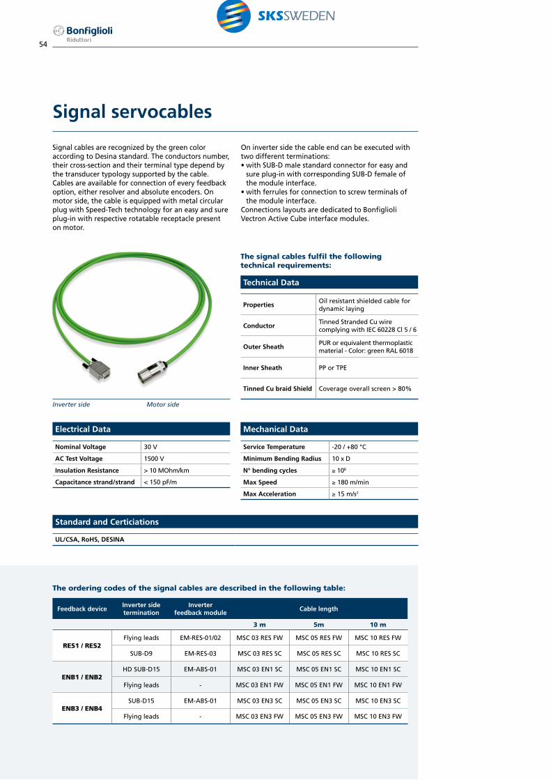
Signal servocables
Signal cables are recognized by the green color according to Desina standard. The conductors number, their cross-section and their terminal type depend by the transducer typology supported by the cable.Cables are available for connection of every feedback option, either resolver and absolute encoders. On motor side, the cable is equipped with metal circular plug with Speed-Tech technology for an easy and sure plug-in with respective rotatable receptacle present on motor.
On inverter side the cable end can be executed with two different terminations:• with SUB-D male standard connector for easy and
sure plug-in with corresponding SUB-D female of the module interface.
• with ferrules for connection to screw terminals of the module interface.
Connections layouts are dedicated to Bonfiglioli Vectron Active Cube interface modules.
The signal cables fulfil the following technical requirements:
The ordering codes of the signal cables are described in the following table:
Technical Data
PropertiesOil resistant shielded cable for dynamic laying
ConductorTinned Stranded Cu wire complying with IEC 60228 Cl 5 / 6
Outer SheathPUR or equivalent thermoplastic material - Color: green RAL 6018
Inner Sheath PP or TPE
Tinned Cu braid Shield Coverage overall screen > 80%
Electrical Data
Nominal Voltage 30 V
AC Test Voltage 1500 V
Insulation Resistance > 10 MOhm/km
Capacitance strand/strand < 150 pF/m
Mechanical Data
Service Temperature -20 / +80 °C
Minimum Bending Radius 10 x D
N° bending cycles ≥ 106
Max Speed ≥ 180 m/min
Max Acceleration ≥ 15 m/s2
Inverter side Motor side
Feedback deviceInverter side termination
Inverter feedback module
Cable length
3 m 5m 10 m
RES1 / RES2Flying leads EM-RES-01/02 MSC 03 RES FW MSC 05 RES FW MSC 10 RES FW
SUB-D9 EM-RES-03 MSC 03 RES SC MSC 05 RES SC MSC 10 RES SC
ENB1 / ENB2HD SUB-D15 EM-ABS-01 MSC 03 EN1 SC MSC 05 EN1 SC MSC 10 EN1 SC
Flying leads - MSC 03 EN1 FW MSC 05 EN1 FW MSC 10 EN1 FW
ENB3 / ENB4SUB-D15 EM-ABS-01 MSC 03 EN3 SC MSC 05 EN3 SC MSC 10 EN3 SC
Flying leads - MSC 03 EN3 FW MSC 05 EN3 FW MSC 10 EN3 FW
Standard and Certiciations
UL/CSA, RoHS, DESINA

55
Power and signal cable marking follows the label and wire colors reported in the pages 48 and 49.
Power cable layout
E
D
AB C
Signal cable layout
E
E
DD
A
A
B C
C
Connector size A B C D[m] [mm] [mm] [mm]
Power CableC1 / C3 3 - 5 - 10
according to designation
15076 28
C2 / C4 93 46
Signal Cable -3 - 5 - 10
according to designation
150 76 28
Wiresection
Brakeoption
Emax
[mm2] [mm]
Power Cable
1.5NB 11.6
B 12.8
2.5NB 13
B 14.2
4NB 14.7
B 16.3
10NB 19.7
B 21.8
Feedbackdesignation
E
[mm]
Signal Cable
RES 8.6
EN1 8.7
EN3 8.6

56
Motion application requires the use of precision planetary gearboxes to adapt speeds and torques, while ensuring the precision demanded by the application.Bonfiglioli Riduttori has chosen to use planetary gearboxes with the BMD range of servo motors. Bonfiglioli precision planetary gearboxes (PPG) match with BMD Permanent Magnet synchronous motors and provide industrial motion control equipment with torque multiplication and proper inertial matching.These gearheads combined with powerful drive electronics are designed for servo applications requiring highest standards in terms of dynamics, precision, robustness, durability, and long trouble-free operation.
Low backlash at a competitive price.The LC Series of planetary gearboxes is characterized by low backlash, silent running and easy motor coupling.
High precision for excellent results.The MP Series of low backlash planetary gearboxes is characterized by a wide range of mounting configurations, silent running, and superbly easy motor coupling.
Maximum precision for highly dynamic applications.The TQ Series of precision planetary gearboxes is designed to deliver the highest level of transmission precision. Low backlash combined with a high torsional stiffness guarantees a very performing product, for in high dynamic and reversing applications. The technical design of this gearbox also allows high axial and radial loads on the output shaft.
Servo gearheads

57
Notes: Input speed lower than 3000 min-1.Safety factor 1 < S ≤ 4.For any additional technical information about gearboxes selection see relevant catalogues.
TypeMotor
stall torqueRatios
Motorinertia
[Nm] 3:1 4:1 5:1 7:1 10:1 16:1 20:1 25:1 40:1 50:1 70:1 kgm2 x 10-3
BMD 65
0.85LC 050 LC 050 LC 050 LC 050 LC 090 LC 090 LC 090 LC 090 LC 090 LC 120
0.02LC 070 LC 120 LC 120
1.7LC 050 LC 050 LC 050 LC 070 LC 070 LC 090 LC 090 LC 090 LC 120 LC 120
0.04LC 070 LC 070 LC 070 LC 090 LC 090 LC 120 LC 120
2.2LC 050 LC 050 LC 050 LC 070 LC 090 LC 090 LC 090 LC 120 LC 120 LC 120
0.06LC 070 LC 070 LC 070 LC 090 LC 120
BMD 82
3.2LC 050 LC 070 LC 070 LC 070 LC 090 LC 120 LC 120 LC 120 LC 155 LC 155
0.14LC 070 LC 090 LC 090 LC 090 LC 120 LC 155
4.4LC 070 LC 070 LC 070 LC 070 LC 120 LC 120 LC 120 LC 120 LC 155 LC 155
0.17LC 090 LC 090 LC 090 LC 090 LC 155
BMD 102
7.2LC 090 LC 090 LC 090 LC 120 LC 120 LC 155 LC 155 LC 155 LC 155
0.34LC 120 LC 155
9.6LC 090 LC 090 LC 090 LC 120 LC 155 LC 155 LC 155 LC 155
0.47LC 120
BMD 118
10.2LC 090 LC 120 LC 120 LC 120 LC 155 LC 155 LC 155 LC 155
0.9LC 120
14LC 120 LC 120 LC 120 LC 120 LC 155 LC 155 LC 155
0.99
BMD 145
16.8LC 120 LC 120 LC 120 LC 155 LC 155 LC 155
1.4LC 155
22LC 120 LC 120 LC 120 LC 155 LC 155
1.76LC 155
BMD 170
34LC 155 LC 155 LC 155 LC 155
2.9
45LC 155 LC 155 LC 155
4.75
Ratios from 3:1 to 70:1
Distribution of gearbox output torque [Nm]
3 4 5 7 10 16 20 25 40 50 70
LC 050 10 12 12 12 - 12 12 12 - - -
LC 070 18 25 25 25 18 25 25 25 25 25 25
LC 090 37 43 43 43 37 43 43 43 43 43 43
LC 120 95 110 110 110 95 110 110 110 110 110 110
LC 155 250 300 300 300 250 300 300 300 300 300 300
BMD Servomotor / LC series Precision Planetary Gearbox combination

58
BMD Servomotor / MP series Precision Planetary Gearbox combination
Notes: Input speed lower than 3000 min-1.Safety factor 1 < S ≤ 4.For any additional technical information about gearboxes selection see relevant catalogues.
TypeMotor
stall torqueRatios
Motorinertia
[Nm] 3:1 4:1 5:1 6:1 7:1 10:1 16:1 20:1 25:1 40:1 50:1 70:1 kgm2 x 10-3
BMD 65
0.85MP 053 MP 053 MP 053 MP 053 MP 053 MP 060 MP 080 MP 080 MP 080
0.02MP 060 MP 060 MP 060 MP 080
1.7MP 053 MP 053 MP 053 MP 053 MP 053 MP 060 MP 060 MP 080 MP 080 MP 080 MP 105 MP 105
0.04MP 060 MP 060 MP 060 MP 060 MP 060 MP 080 MP 080 MP 080 MP 080 MP 105 MP 105 MP 105
2.2MP 053 MP 053 MP 053 MP 053 MP 053 MP 060 MP 080 MP 080 MP 080 MP 080 MP 105 MP 105
0.06MP 060 MP 060 MP 060 MP 060 MP 060 MP 080 MP 080 MP 080 MP 105 MP 105 MP 105
BMD 82
3.2MP 053 MP 053 MP 060 MP 060 MP 060 MP 080 MP 080 MP 080 MP 105 MP 105 MP 105 MP 130
0.14MP 060 MP 060 MP 080 MP 080 MP 080 MP 105 MP 105 MP 105 MP 130 MP 130 MP 160
4.4MP 060 MP 060 MP 060 MP 060 MP 060 MP 080 MP 080 MP 080 MP 105 MP 105 MP 105 MP 130
0.17MP 080 MP 080 MP 080 MP 105 MP 105 MP 105 MP 130 MP 130 MP 160
BMD 102
7.2MP 080 MP 080 MP 080 MP 080 MP 080 MP 105 MP 105 MP 105 MP 130 MP 130 MP 130 MP 160
0.34MP 105 MP 105 MP 130 MP 160 MP 160
9.6MP 080 MP 080 MP 080 MP 105 MP 105 MP 105 MP 105 MP 105 MP 130 MP 130 MP 130 MP 160
0.47MP 130 MP 160 MP 160
BMD 118
10.2MP 105 MP 105 MP 105 MP 105 MP 105 MP 130 MP 130 MP 130 MP 130 MP 130 MP 160 MP 190
0.9MP 160 MP 160 MP 160 MP 160
14MP 105 MP 105 MP 105 MP 105 MP 105 MP 130 MP 130 MP 130 MP 130 MP 130 MP 160 MP 190
0.99MP 160 MP 160 MP 160 MP 160
BMD 145
16.8
MP 105 MP 105 MP 105 MP 105 MP 105 MP 130 MP 130 MP 130 MP 160 MP 160 MP 190
1.4MP 130 MP 130 MP 160 MP 160 MP 160 MP 190 MP 190
MP 190 MP 190
22
MP 105 MP 105 MP 105 MP 105 MP 130 MP 160 MP 130 MP 130 MP 160 MP 160 MP 190
1.76MP 130 MP 160 MP 160 MP 190 MP 190
MP 190 MP 190
BMD 170
34MP 105 MP 105 MP 130 MP 130 MP 130 MP 160 MP 160 MP 160 MP 190
2.9MP 130 MP 190 MP 190
45MP 130 MP 130 MP 130 MP 130 MP 130 MP 190 MP 160 MP 160 MP 190
4.75MP 160 MP 160 MP 190 MP 190
Ratios from 3:1 to 70:1
Distribution of gearbox output torque [Nm]
3 4 5 6 7 10 16 20 25 40 50 70
MP 053 12 15 15 15 15 - 20 20 20 - - -
MP 060 18 25 25 25 25 18 30 30 30 30 30 30
MP 080 40 50 50 50 50 40 70 70 70 70 70 70
MP 105 100 140 140 140 140 100 170 170 170 170 170 170
MP 130 215 380 380 380 380 215 450 450 450 450 450 450
MP 160 350 500 500 500 500 350 700 700 700 700 700 700
MP 190 500 700 700 700 700 500 1000 1000 1000 1000 1000 1000

59
Notes: Input speed lower than 3000 min-1.Safety factor 1 < S ≤ 4.For any additional technical information about gearboxes selection see relevant catalogues.
Ratios from 3:1 to 70:1
Distribution of gearbox output torque [Nm]
3 4 5 7 10 16 20 25 40 50 70
TQ 060 21 30 30 25 20 30 30 30 30 30 25
TQ 070 45 70 70 60 40 70 70 70 70 70 60
TQ 090 130 200 180 160 110 200 180 180 200 180 160
TQ 130 260 400 400 360 280 400 400 400 400 400 360
TQ 160 530 800 800 750 550 800 800 800 800 800 750
BMD Servomotor / TQ series Precision Planetary Gearbox combination
TypeMotor
stall torqueRatios
Motorinertia
[Nm] 3:1 4:1 5:1 7:1 10:1 16:1 20:1 25:1 40:1 50:1 70:1 kgm2 x 10-3
BMD 65
0.85TQ 060 TQ 060 TQ 060 TQ 060 TQ 070 TQ 070 TQ 070
0.02TQ 070
1.7TQ 060 TQ 060 TQ 060 TQ 060 TQ 060 TQ 060 TQ 070 TQ 070 TQ 070
0.04TQ 070 TQ 070 TQ 070 TQ 070 TQ 070 TQ 070
2.2TQ 060 TQ 060 TQ 060 TQ 060 TQ 070 TQ 070 TQ 070 TQ 070
0.06TQ 070 TQ 070 TQ 070 TQ 070
BMD 82
3.2TQ 070 TQ 070 TQ 070 TQ 070 TQ 090 TQ 070 TQ 070 TQ 090 TQ 090 TQ 090
0.14
4.4TQ 070 TQ 070 TQ 070 TQ 070 TQ 090 TQ 090 TQ 090 TQ 090 TQ 090
0.17
BMD 102
7.2TQ 070 TQ 090 TQ 090 TQ 070 TQ 090 TQ 090 TQ 090 TQ 090 TQ 090
0.34TQ 090 TQ 090
9.6TQ 070 TQ 090 TQ 090 TQ 070 TQ 090 TQ 090 TQ 130 TQ 130 TQ 130
0.47TQ 090 TQ 090
BMD 118
10.2TQ 070 TQ 070 TQ 070 TQ090 TQ090 TQ 130 TQ 130 TQ 130 TQ 160 TQ 160
0.9TQ 090 TQ 090 TQ 090
14TQ 090 TQ 090 TQ 090 TQ 090 TQ130 TQ 130 TQ 130 TQ 130 TQ 160 TQ 160
0.99TQ130
BMD 145
16.8TQ 090 TQ 090 TQ 090 TQ 090 TQ130 TQ 160 TQ 160 TQ 160 TQ 160
1.4TQ130
22TQ 090 TQ 090 TQ 090 TQ 090 TQ130 TQ 160 TQ 160 TQ 160
1.76TQ130
BMD 170
34TQ 090 TQ 090 TQ 090 TQ130 TQ 160 TQ 160 TQ 160
2.9TQ 130 TQ 130 TQ 130
45TQ 130 TQ 130 TQ 130 TQ130 TQ 160 TQ 160
4.75

Branches and facilitiesOur branches
ITA1Bonfiglioli Riduttori S.p.A.Gearmotor assembly plantPrecison gearbox manufacturing & assembly plantVignola, Modena
BMRBonfiglioli Mechatronics ResearchBrushless motor productionRovereto, Trento
BU Industrial Headquarter BU Wind & MobileBU Regenerative & Photovoltaic
ITA2Bonfiglioli Riduttori S.p.A.Casting and gearcutting plantCalderara di Reno, Bologna
B2Bonfiglioli Riduttori S.p.A.Assembly HDP, HDO, 300 seriesCalderara di Reno, Bologna
HQBonfiglioli Riduttori S.p.A.Lippo di Calderara, Bologna
B6Bonfiglioli Riduttori S.p.A.Planetary gearboxes manufacturing & assembly plantForlì
BTPLBonfiglioli Transmission PvtGearmotors and planetary gearbox manufacturing and assembly plantChennai, India
BVNBonfiglioli VietnamElectric motor plantHo Chi Min, Vietnam
BSKBonfiglioli Slovakia SroLarge gearboxes manufacturing plantPovazska BystricaSlovakia Republic
BVBonfiglioli Vectron GmbHInverter plantKrefeld, Germany
Our production facilities
BonfiglioliCanada
BonfiglioliUSA
BonfiglioliFrance
BonfiglioliBrasil
Bonfiglioli United Kingdom
BonfiglioliSouth Africa
BonfiglioliDeutschland
BonfiglioliIndia
BonfiglioliÖsterreich
BonfiglioliSouth East Asia
BonfiglioliItalia
BonfiglioliVietnam
BonfiglioliAustralia
BonfiglioliTürkiye
BonfiglioliNew Zealand
BonfiglioliChina
Tecnotrans Bonfiglioli

61
Bonfiglioli is your partner worldwide for power transmission and motion control.
Customer satisfaction has always been one of Bonfiglioli’s key values. It is pursued around the world, and in a wide range of contexts, by a network of subsidiaries located in 17 countriesand on 5 continents.
Each subsidiary provides rapid and efficient pre-sales and after-sales service, and can guarantee prompt deliveries from local assembly plant and warehouses.
In addition to our directly controlled subsidiaries, Bonfiglioli can also rely on an extensive network of authorised dealers, selected for their ability to guarantee excellent pre-sales and after-sales assistance.
To give everybody the chance to purchase a Bonfiglioli product - anywhere.
This is the ambitious objective that drives the development of our added value sales networks, off and on-line.
BEST (Bonfiglioli Excellence Service Team) is one of the most modern sales organisations in the field of power transmission.
Our BEST partners can benefit from our local assembly plant and warehouses, our training courses and tools, and our promotional activities.
For the first time ever, manufacturer and distributors are working together from the product assembly stage and in the design of new applications, in a sharing process that sees one party transferring know-how and technology and the other partly providing a thorough knowledge of the local market.
Bonfiglioli worldwide network.
Bonfiglioli ItaliaIndustrial, PhotovoltaicVia Sandro Pertini lotto 7b - 20080 Carpiano (Milano)Tel. (+39) 02 985081 - Fax (+39) 02 985085817www.bonfiglioli.itBonfiglioli Mechatronic ResearchVia F. Zeni 8 - 38068 Rovereto (Trento)Tel. (+39) 0464 443435/36 - Fax (+39) 0464 443439www.bonfiglioli.it
Bonfiglioli New Zealand88 Hastie Avenue, Mangere Bridge, Auckland2022, New Zealand - PO Box 11795, EllerslieTel. (+64) 09 634 6441 - Fax (+64) 09 634 6445www.bonfiglioli.co.nz
Bonfiglioli ÖsterreichMolkereistr 4 - A-2700 Wiener NeustadtTel. (+43) 02622 22400 - Fax (+43) 02622 22386www.bonfiglioli.at
Bonfiglioli South East Asia24 Pioneer Crescent #02-08West Park Bizcentral - Singapore, 628557Tel. (+65) 6268 9869 - Fax. (+65) 6268 9179www.bonfiglioli.com
Bonfiglioli South Africa55 Galaxy Avenue,Linbro Business Park - SandtonTel. (+27) 11 608 2030 OR - Fax (+27) 11 608 2631www.bonfiglioli.co.za
Bonfiglioli Türkiye Atatürk Organize Sanayi Bölgesi,10044 Sk. No. 9, 35620 Çigli - IzmirTel. +90 (0) 232 328 22 77 (pbx)Fax +90 (0) 232 328 04 14www.bonfiglioli.com.tr
Bonfiglioli United KingdomIndustrial, PhotovoltaicUnit 7, Colemeadow RoadNorth Moons Moat - Redditch, Worcestershire B98 9PBTel. (+44) 1527 65022 - Fax (+44) 1527 61995www.bonfiglioli.co.ukMobile, Wind3 - 7 Grosvenor Grange, WoolstonWarrington - Cheshire WA1 4SFTel. (+44) 1925 852667 - Fax (+44) 1925 852668www.bonfiglioli.co.uk
Bonfiglioli USA3541 Hargrave Drive Hebron, Kentucky 41048Tel. (+1) 859 334 3333 - Fax (+1) 859 334 8888www.bonfiglioliusa.com
Bonfiglioli VietnamLot C-9D-CN My Phuoc Industrial Park 3Ben Cat - Binh Duong ProvinceTel. (+84) 650 3577411 - Fax (+84) 650 3577422www.bonfiglioli.vn
Bonfiglioli Australia2, Cox Place Glendenning NSW 2761Locked Bag 1000 Plumpton NSW 2761Tel. (+ 61) 2 8811 8000 - Fax (+ 61) 2 9675 6605www.bonfiglioli.com.au
Bonfiglioli BrasilTravessa Cláudio Armando 171Bloco 3 - CEP 09861-730 - Bairro AssunçãoSão Bernardo do Campo - São PauloTel. (+55) 11 4344 2323 - Fax (+55) 11 4344 2322www.bonfigliolidobrasil.com.br
Bonfiglioli Canada2-7941 Jane Street - Concord, Ontario L4K 4L6Tel. (+1) 905 7384466 - Fax (+1) 905 7389833www.bonfigliolicanada.com
Bonfiglioli China Unit D, 8th Floor, Building D, BenQ Plaza, No.207 Songhong Road, Shanghai 200335Tel. (+86) 21 60391118 - Fax (+86) 59702957www.bonfiglioli.cn
Bonfiglioli Deutschland Industrial, Mobile, WindSperberweg 12 - 41468 NeussTel. +49 (0) 2131 2988 0 - Fax +49 (0) 2131 2988 100www.bonfiglioli.deIndustrial, Photovoltaic Europark Fichtenhain B6 - 47807 KrefeldTel. +49 (0) 2151 8396 0 - Fax +49 (0) 2151 8396 999www.vectron.net
Bonfiglioli España Industrial, Mobile, WindTecnotrans Bonfiglioli S.A.Pol. Ind. Zona Franca sector C, calle F, n°608040 BarcelonaTel. (+34) 93 4478400 - Fax (+34) 93 3360402www.tecnotrans.comPhotovoltaicBonfiglioli Renewable Power Conversion Spain, SLRibera del Loira, 46 - Edificio 2 - 28042 MadridTel. (+34) 91 5030125 - Fax (+34) 91 5030099www.tecnotrans.com
Bonfiglioli France 14 Rue Eugène PottierZone Industrielle de Moimont II - 95670 Marly la VilleTel. (+33) 1 34474510 - Fax (+33) 1 34688800www.bonfiglioli.fr
Bonfiglioli India IndustrialBonfiglioli Transmission PVT ltd.Survey No. 528, Perambakkam High RoadMannur Village - Sriperumbudur Taluk 602105 www.bonfiglioli.inMobile, WindBonfiglioli Transmission PVT ltd.PLOT AC7-AC11 Sidco Industrial EstateThirumudivakkam - Chennai 600 044Tel. +91(0) 44 24781035 - 24781036 - 24781037Fax +91(0) 44 24780091 - 24781904www.bonfiglioli.inPhotovoltaicBonfiglioli Renewable Power Conversion India (P) LtdNo. 543, 14th Cross, 4th Phase, Peenya Industrial Area, Bangalore - 560 058Tel. +91 80 2836 1014/15 - Fax +91 80 2836 1016www.bonfiglioli.in

BMD Brushless motor photos used inside this catalogue do not represent the real product colour.The actual colour is black (RAL 9005). Silver dressing has to be intended for marketing and promotional purposes only.

Bonfiglioli has been designing and developing innovativeand reliable power transmission and control solutionsfor industry, mobile machinery and renewable energyapplications since 1956.
BR_CAT_BMD_STD_ENG_R02_1HEADQUARTERS
Bonfiglioli Riduttori S.p.A.Via Giovanni XXIII, 7/A40012 Lippo di Calderara di RenoBologna (Italy)
tel: +39 051 647 3111fax: +39 051 647 [email protected]