bomba de lodos SC-65Lman
53
SC-65L TRIPLEX 1 All drawings and specifications subject to change without notice. REVISED 02/22/06 60122A999
-
Upload
ferran-alf -
Category
Documents
-
view
14 -
download
3
description
bomba de lodos SC-65Lmanuso comun extraccion de petroleo
Transcript of bomba de lodos SC-65Lman

SC-65L TRIPLEX
1 All drawings and specifications subject to change without notice. REVISED 02/22/06 60122A999
SC-65L TRIPLEX
2 REVISED 02/22/06 60122A999All drawings and specifications subject to change without notice.
Table of Contents
POWER END ENGINEERING DATA ............................................................................................................ 4 LIQUID END ENGINEERING DATA ............................................................................................................ 4 LIQUID END ENGINEERING DATA (CONTINUED) ................................................................................. 5 GENERAL ENGINEERING DATA ................................................................................................................. 5 PUMP NAME PLATE ..................................................................................................................................... 6 PUMP CROSS-SECTION ................................................................................................................................ 7 PUMP GENERAL DIMENSION ..................................................................................................................... 8
INSTALLATION, OPERATION, LUBRICATION, MAINTENANCE ANDSTORAGE INSTRUCTIONS .......................................................................................................................... 10 SAFETY......................................................................................................................................................... 10 STORAGE ..................................................................................................................................................... 10 PUMP LOCATION & PIPING DESIGN .................................................................................................... 10 SUCTION PIPING ........................................................................................................................................ 10 ACCELERATION HEAD ............................................................................................................................. 11 DISCHARGE PIPING .................................................................................................................................. 11 BYPASS PIPING .......................................................................................................................................... 12 SUGGESTED PIPING SYSTEM FOR PLUNGER PUMPS ...................................................................... 13 LUBRICATION............................................................................................................................................. 14 V-BELT DRIVE ............................................................................................................................................ 14 DIRECTION OF ROTATION ...................................................................................................................... 15 AUTOMATIC (SAFETY) SHUTDOWNS .................................................................................................. 15
CRANKSHAFT ASSEMBLY GENERAL ..................................................................................................................................................... 16 TAPERED ROLLER BEARINGS ............................................................................................................... 16
INSTALLING CRANKSHAFT GENERAL ..................................................................................................................................................... 17 SHIM ADJUSTMENT OF TAPERED ROLLER BEARINGS .................................................................. 17 INSTALLATION OF CRANKSHAFT OIL SEAL ..................................................................................... 17
CONNECTING ROD, CROSSHEAD, AND CROSSHEAD PIN ASSEMBLY GENERAL ..................................................................................................................................................... 18 INSTALLING WRIST PIN BUSHINGS ..................................................................................................... 18 PINNING THE CROSSHEAD..................................................................................................................... 19 ORDER OF ASSEMBLY .............................................................................................................................. 19 PRECISION CRANKPIN (CRANKTHROW) BEARINGS ...................................................................... 19
WIPER BOX ASSEMBLY GENERAL ..................................................................................................................................................... 21 “POLY PAK” SEAL ...................................................................................................................................... 21 MECHANICAL OIL SEAL .......................................................................................................................... 21 INSERTING THE PLUNGER ...................................................................................................................... 21
SC-65L TRIPLEX
3 All drawings and specifications subject to change without notice. REVISED 02/22/06 60122A999
Table of Contents (continued)
STUFFING BOX, PACKING & PLUNGER ASSEMBLIES GENERAL ..................................................................................................................................................... 22 SPRING LOADED PACKING .................................................................................................................... 22 HI/LO GLAND ADJUSTABLE PACKING ................................................................................................ 22 INSERTING THE PLUNGER ...................................................................................................................... 23 INSTALLING THE GLAND ........................................................................................................................ 23 INSTALLING THE STUFFING BOX ......................................................................................................... 23 CONNECTING THE PLUNGER ................................................................................................................ 24 PACKING ...................................................................................................................................................... 24 PLUNGERS ................................................................................................................................................... 24
MYERS/APLEX DUAL-STEM GUIDED & DISC VALVE SYSTEM GENERAL ..................................................................................................................................................... 25 DISC VALVE CONSTRUCTION ................................................................................................................ 25 SETTING THE VALVE SEAT ..................................................................................................................... 25 INSTALLING VALVE SEAT ....................................................................................................................... 26 INSTALLING O-RING, DUAL STEM GUIDED SPRING AND CAGE................................................... 26 INSTALLING DISC, SPRING, DISC VALVES & STEM ......................................................................... 26 PULLING THE VALVE SEAT..................................................................................................................... 26 REMOVING VALVE SEAT ......................................................................................................................... 27
TROUBLE LOCATION & REMEDY ............................................................................................................ 28
ILLUSTRATED PARTS BREAK DOWN
POWER FRAME ASSEMBLY, CONN. ROD, CROSSHEAD & WIPER BOX ASSEMBLY .................... 32CRANKSHAFT ASSEMBLY 2 3/4” STROKE BEARINGLESS HYD. MOTOR R.H. .............................. 33BEARINGLESS HYD. MOTOR 2 3/4” LEFT HAND .................................................................................. 34AUBURN PLANETARY 2 3/4” RIGHT HAND ........................................................................................... 35AUBURN PLANETARY 2 3/4” LEFT HAND. ............................................................................................. 36CRANKSHAFT ASSEMBLY 2 3/4” RIGHT HAND ..................................................................................... 37CRANKSHAFT ASSEMBLY 2 3/4” LEFT HAND ........................................................................................ 38
FLUID END ASSEMBLY DUCTILE IRON ........................................................................................................................................... 39
DUAL STEM GUIDE VALVE ASSEMBLY & PULLER .............................................................................. 40DISC VALVE ASSEMBLY & PULLER ......................................................................................................... 42ABRASION RESISTANT VALVE ASSEMBLY & PULLER ....................................................................... 45
STUFFING BOX ASSEMBLY ......................................................................................................................... 46
PACKING 120X & 805 PACKING ASSEMBLY ........................................................................................................... 47 COMPRESSION PACKING ASSEMBLY .................................................................................................. 48 838 PACKING ASSEMBLY ......................................................................................................................... 49 HI/LO PACKING ASSEMBLY .................................................................................................................... 50
SC-65L TRIPLEX
4 REVISED 02/22/06 60122A999All drawings and specifications subject to change without notice.
MYERS/APLEX INDUSTRIES, INC.Ashland, Ohio U.S.A.
SC-65L TRIPLEX PLUNGER PUMP
POWER END ENGINEERING DATA
Model Triplex Pump ................................................................................................................... SC-65LMax. Input HP @ Speed .................................................................................................. 92 @ 550 rpmRated Continuous Plunger Load ................................................................................................ 7,216 lbsStroke ........................................................................................................................................... 2 3/4”Max. Rated Continuous Speed ................................................................................................... 550 rpmNormal Continuous Speed Range ............................................................................................... 100 rpmMinimum Speed ......................................................................................................................... 100 rpmOil Capacity ........................................................................................................................... 8 U.S. qrtsViscosity, S.S.U. @ 210oF ......................................................................................................... 70 to 84Power End Oiling System ............................................................................................... Splash & ScoopPower Frame, One-Piece ......................................................................................................... Cast IronCrosshead, Full Cylindrical ....................................................................................................... Cast IronCrosshead, Dia. x Length ........................................................................................................ 4” x 4 1/2”Crankshaft ............................................................................................................................. Ductile IronCrankshaft Diameters: At Drive Extension ........................................................................................................... 2.500/2.499” At Tapered Roller Bearings .......................................................................................................... 3.35” At Crankpin Bearings, Dia. x Length .................................................................................... 2 3/4” x 2”Crosshead (Wrist) Pin, Case-Hardened and Ground ............................................................... AISI 8620Wrist Pin Bushing, SAE 660, Dia. x Width ............................................................................ 1 5/16” x 2”Main Bearings, Tapered Roller ..................................................................................................... TimkenCrankpin Bearings, Precision Automotive ..................................................... Steel Backed, Babbitt-LinedExtension (Pony) Rod ................................................................................................................ 416 S.S.Extension Rod Dia., ....................................................................................................................... 1 1/4”Connecting Rod, Automotive Type ........................................................................................ Ductile IronAverage Crosshead Speed: At 550 rpm ............................................................................................................................. 252 fpmMinimum Life Expectancy, Main Bearings,L10........................................................................... 30,000+hr
LIQUID END ENGINEERING DATA
Plunger Size Range, diameter ....................................................................................... 2 3/4” Thru 2 1/4”Max. Continuous Working Pressure .......................................................................................... 1,815 psiHydrostatic Test ....................................................................................................................... 2,725 psiDischarge Connection Size ........................................................................................................ 2” NPTFSuction Connection Size ........................................................................................................... 3” NPTF
SC-65L TRIPLEX
5 All drawings and specifications subject to change without notice. REVISED 02/22/06 60122A999
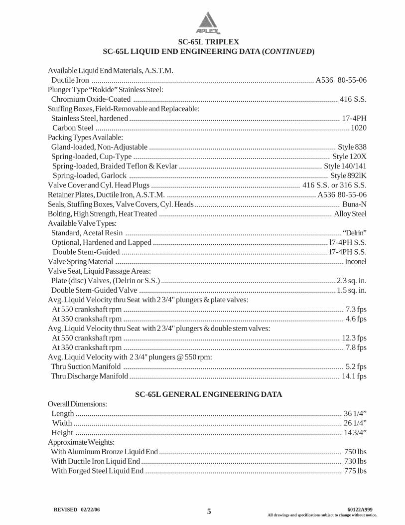
SC-65L LIQUID END ENGINEERING DATA (CONTINUED)
Available Liquid End Materials, A.S.T.M. Ductile Iron ................................................................................................................ A536 80-55-06Plunger Type “Rokide” Stainless Steel: Chromium Oxide-Coated ....................................................................................................... 416 S.S.Stuffing Boxes, Field-Removable and Replaceable: Stainless Steel, hardened .......................................................................................................... 17-4PH Carbon Steel ................................................................................................................................ 1020Packing Types Available: Gland-loaded, Non-Adjustable .............................................................................................. Style 838 Spring-loaded, Cup-Type ................................................................................................... Style 120X Spring-loaded, Braided Teflon & Kevlar ........................................................................ Style 140/141 Spring-loaded, Garlock .................................................................................................... Style 892lKValve Cover and Cyl. Head Plugs ........................................................................... 416 S.S. or 316 S.S.Retainer Plates, Ductile Iron, A.S.T.M. ........................................................................... A536 80-55-06Seals, Stuffing Boxes, Valve Covers, Cyl. Heads ......................................................................... Buna-NBolting, High Strength, Heat Treated ....................................................................................... Alloy SteelAvailable Valve Types: Standard, Acetal Resin ............................................................................................................. “Delrin” Optional, Hardened and Lapped ........................................................................................ l7-4PH S.S. Double Stem-Guided ........................................................................................................ l7-4PH S.S.Valve Spring Material ................................................................................................................... InconelValve Seat, Liquid Passage Areas: Plate (disc) Valves, (Delrin or S.S.) ........................................................................................ 2.3 sq. in. Double Stem-Guided Valve ................................................................................................... 1.5 sq. in.Avg. Liquid Velocity thru Seat with 2 3/4" plungers & plate valves: At 550 crankshaft rpm ............................................................................................................... 7.3 fps At 350 crankshaft rpm ............................................................................................................... 4.6 fpsAvg. Liquid Velocity thru Seat with 2 3/4" plungers & double stem valves: At 550 crankshaft rpm ............................................................................................................. 12.3 fps At 350 crankshaft rpm ............................................................................................................... 7.8 fpsAvg. Liquid Velocity with 2 3/4" plungers @ 550 rpm: Thru Suction Manifold ............................................................................................................... 5.2 fps Thru Discharge Manifold .......................................................................................................... 14.1 fps
SC-65L GENERAL ENGINEERING DATAOverall Dimensions: Length ...................................................................................................................................... 36 1/4” Width ....................................................................................................................................... 26 1/4” Height ...................................................................................................................................... 14 3/4”Approximate Weights: With Aluminum Bronze Liquid End ............................................................................................ 750 lbs With Ductile Iron Liquid End ..................................................................................................... 730 lbs With Forged Steel Liquid End ................................................................................................... 775 lbs

SC-65L TRIPLEX
6 REVISED 02/22/06 60122A999All drawings and specifications subject to change without notice.

SC-65L TRIPLEX
7 All drawings and specifications subject to change without notice. REVISED 02/22/06 60122A999

SC-65L TRIPLEX
8 REVISED 02/22/06 60122A999All drawings and specifications subject to change without notice.

SC-65L TRIPLEX
9 All drawings and specifications subject to change without notice. REVISED 02/22/06 60122A999
SC-65L TRIPLEX
10 REVISED 02/22/06 60122A999All drawings and specifications subject to change without notice.
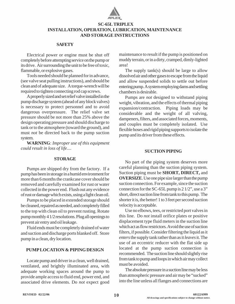
SAFETY
Electrical power or engine must be shut offcompletely before attempting service on the pump orits drive. Air surrounding the unit to be free of toxic,flammable, or explosive gases.
Tools needed should be planned for in advance,(see valve seat pulling instructions), and should beclean and of adequate size. A torque-wrench will berequired to tighten connecting rod cap screws.
A properly sized and set relief valve installed in thepump discharge system (ahead of any block valves)is necessary to protect personnel and to avoiddangerous overpressure. The relief valve setpressure should be not more than 25% above thedesign operating pressure and should discharge totank or to the atmosphere (toward the ground), andmust not be directed back to the pump suctionsystem.
WARNING: Improper use of this equipmentcould result in loss of life....
STORAGE
Pumps are shipped dry from the factory. If apump has been in storage in a humid environment formore than 6 months the crankcase cover should beremoved and carefully examined for rust or watercollected in the power end. Flush out any evidenceof rust or damage which exists, using a light clean oil.
Pumps to be placed in extended storage shouldbe cleaned, repaired as needed, and completely filledto the top with clean oil to prevent rusting. Rotatepump monthly 4 1/2 resolutions. Plug all openings toprevent air entry and oil leakage.
Fluid ends must be completely drained of waterand suction and discharge ports blanked off. Storepump in a clean, dry location.
PUMP LOCATION & PIPING DESIGN
Locate pump and driver in a clean, well drained,ventilated, and brightly illuminated area, withadequate working spaces around the pump toprovide ample access to fluid end, power end, andassociated drive elements. Do not expect good
maintenance to result if the pump is positioned onmuddy terrain, or in a dirty, cramped, dimly-lightedarea!
The supply tank(s) should be large to allowdissolved air and other gases to escape from the liquidand allow suspended solids to settle out beforeentering pump. A system employing dams and settlingchambers is desirable.
Pumps are not designed to withstand pipingweight, vibration, and the effects of thermal pipingexpansion/contraction. Piping loads may beconsiderable and the weight of all valving,dampeners, filters, and associated forces, moments,and couples must be completely isolated. Useflexible hoses and rigid piping supports to isolate thepump and its driver from these effects.
SUCTION PIPING
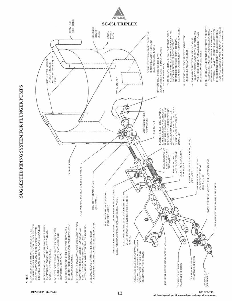
No part of the piping system deserves morecareful planning than the suction piping system.Suction piping must be SHORT, DIRECT, andOVERSIZE. Use one pipe size larger than the pumpsuction connection. For example, since the suctionconnection for the SC-65L pump is 2 1/2”, use a 3”short, direct suction line from tank to this pump. Theshorter it is, the better! 1 to 3 feet per second suctionvelocity is acceptable.
Use no elbows, tees, or restricted port valves inthis line. Do not install orifice plates or positivedisplacement type fluid meters in the suction linewhich act as flow restrictors. Avoid the use of suctionfilters, if possible. Consider filtering the liquid as itenters the supply tank rather than as it leaves it. Theuse of an eccentric reducer with the flat side uplocated at the pump suction connection isrecommended. The suction line should slightly risefrom tank to pump and loops in which air may collectmust be avoided.
The absolute pressure in a suction line may be lessthan atmospheric pressure and air may be “sucked”into the line unless all flanges and connections are
INSTALLATION, OPERATION, LUBRICATION, MAINTENANCEAND STORAGE INSTRUCTIONS
SC-65L TRIPLEX
11 All drawings and specifications subject to change without notice. REVISED 02/22/06 60122A999
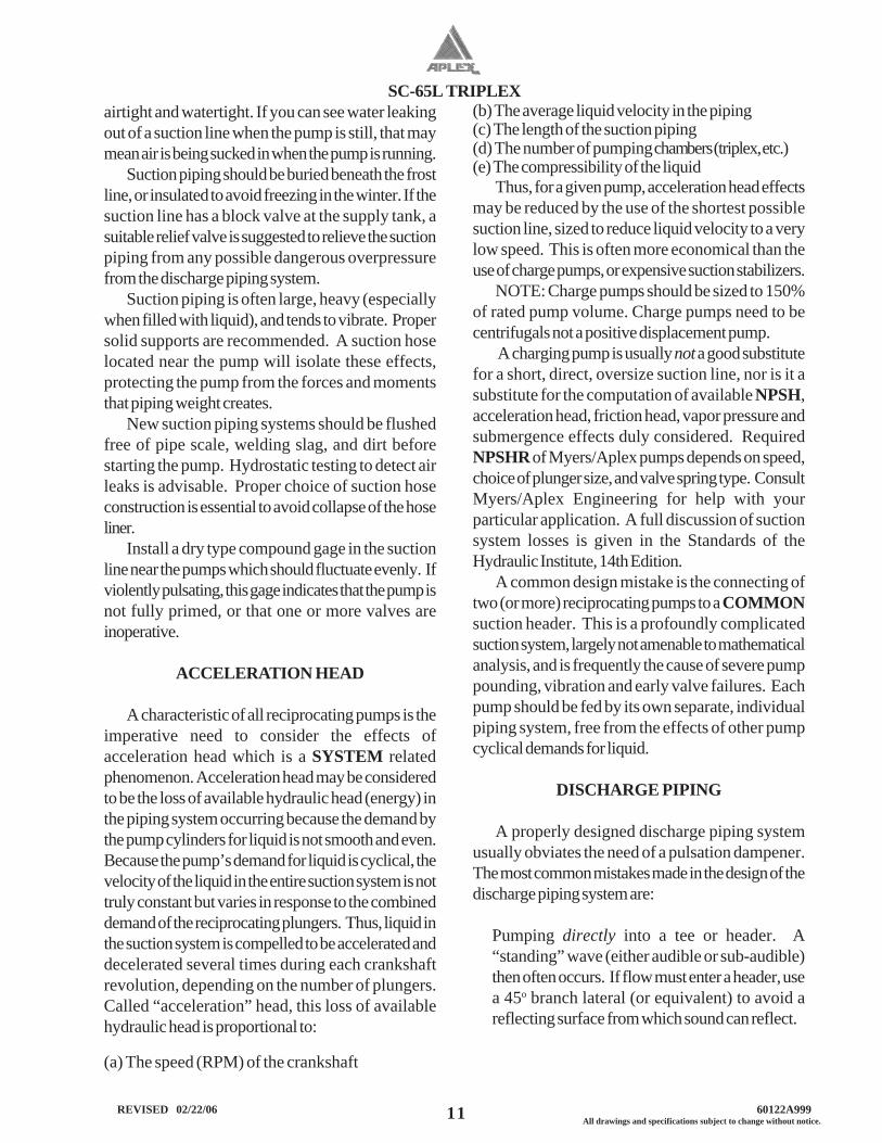
airtight and watertight. If you can see water leakingout of a suction line when the pump is still, that maymean air is being sucked in when the pump is running.
Suction piping should be buried beneath the frostline, or insulated to avoid freezing in the winter. If thesuction line has a block valve at the supply tank, asuitable relief valve is suggested to relieve the suctionpiping from any possible dangerous overpressurefrom the discharge piping system.
Suction piping is often large, heavy (especiallywhen filled with liquid), and tends to vibrate. Propersolid supports are recommended. A suction hoselocated near the pump will isolate these effects,protecting the pump from the forces and momentsthat piping weight creates.
New suction piping systems should be flushedfree of pipe scale, welding slag, and dirt beforestarting the pump. Hydrostatic testing to detect airleaks is advisable. Proper choice of suction hoseconstruction is essential to avoid collapse of the hoseliner.
Install a dry type compound gage in the suctionline near the pumps which should fluctuate evenly. Ifviolently pulsating, this gage indicates that the pump isnot fully primed, or that one or more valves areinoperative.
ACCELERATION HEAD
A characteristic of all reciprocating pumps is theimperative need to consider the effects ofacceleration head which is a SYSTEM relatedphenomenon. Acceleration head may be consideredto be the loss of available hydraulic head (energy) inthe piping system occurring because the demand bythe pump cylinders for liquid is not smooth and even.Because the pump’s demand for liquid is cyclical, thevelocity of the liquid in the entire suction system is nottruly constant but varies in response to the combineddemand of the reciprocating plungers. Thus, liquid inthe suction system is compelled to be accelerated anddecelerated several times during each crankshaftrevolution, depending on the number of plungers.Called “acceleration” head, this loss of availablehydraulic head is proportional to:
(a) The speed (RPM) of the crankshaft
(b) The average liquid velocity in the piping(c) The length of the suction piping(d) The number of pumping chambers (triplex, etc.)(e) The compressibility of the liquid
Thus, for a given pump, acceleration head effectsmay be reduced by the use of the shortest possiblesuction line, sized to reduce liquid velocity to a verylow speed. This is often more economical than theuse of charge pumps, or expensive suction stabilizers.
NOTE: Charge pumps should be sized to 150%of rated pump volume. Charge pumps need to becentrifugals not a positive displacement pump.
A charging pump is usually not a good substitutefor a short, direct, oversize suction line, nor is it asubstitute for the computation of available NPSH,acceleration head, friction head, vapor pressure andsubmergence effects duly considered. RequiredNPSHR of Myers/Aplex pumps depends on speed,choice of plunger size, and valve spring type. ConsultMyers/Aplex Engineering for help with yourparticular application. A full discussion of suctionsystem losses is given in the Standards of theHydraulic Institute, 14th Edition.
A common design mistake is the connecting oftwo (or more) reciprocating pumps to a COMMONsuction header. This is a profoundly complicatedsuction system, largely not amenable to mathematicalanalysis, and is frequently the cause of severe pumppounding, vibration and early valve failures. Eachpump should be fed by its own separate, individualpiping system, free from the effects of other pumpcyclical demands for liquid.
DISCHARGE PIPING
A properly designed discharge piping systemusually obviates the need of a pulsation dampener.The most common mistakes made in the design of thedischarge piping system are:
Pumping directly into a tee or header. A“standing” wave (either audible or sub-audible)then often occurs. If flow must enter a header, usea 45o branch lateral (or equivalent) to avoid areflecting surface from which sound can reflect.
SC-65L TRIPLEX
12 REVISED 02/22/06 60122A999All drawings and specifications subject to change without notice.
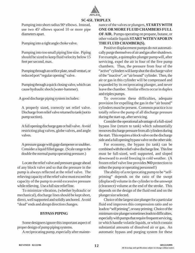
Pumping into short radius 90o elbows. Instead,use two 45o elbows spaced 10 or more pipediameters apart.
Pumping into a right angle choke valve.
Pumping into too small piping line size. Pipingshould be sized to keep fluid velocity below 15feet per second, max.
Pumping through an orifice plate, small venturi, orreduced port “regular opening” valve.
Pumping through a quick closing valve, which cancause hydraulic shock (water-hammer).
A good discharge piping system includes:
A properly sized, correctly set relief valve.Discharge from relief valve returned to tank (not topump suction).
A full opening discharge gate or ball valve. Avoidrestricting plug valves, globe valves, and anglevalves.
A pressure gauge with gage dampener or snubber.Consider a liquid filled gauge. (Scale range to bedouble the normal pump operating pressure.)
Locate the relief valve and pressure gauge aheadof any block valve and so that the pressure in thepump is always reflected at the relief valve. Therelieving capacity of the relief valve must exceed thecapacity of the pump to avoid excessive pressurewhile relieving. Use a full size relief line.
To minimize vibration, (whether hydraulic ormechanical), discharge lines should be kept short,direct, well supported and solidly anchored. Avoid“dead” ends and abrupt direction changes.
BYPASS PIPING
Some designers ignore this important aspect ofproper design of pump piping systems.
A reciprocating pump, especially after mainte-
nance of the valves or plungers, STARTS WITHONE OR MORE FLUID CHAMBERS FULLOF AIR. Pumps operating on propane, butane, orother volatile liquids START WITH VAPOR INTHE FLUID CHAMBER(S).
Positive displacement pumps do not automati-cally purge themselves of air and gas after shutdown.For example, a quintuplex plunger pump will, afterservicing, expel the air in four of the five pumpchambers. Thus, the pressure from four of the“active” cylinders will keep shut the discharge valveof the “inactive”, or “air bound” cylinder. Then, theair or gas in this cylinder will be compressed andexpanded by its reciprocating plunger, and neverleave the chamber. Similar effects occur in duplexand triplex pumps.
To overcome these difficulties, adequateprovision for expelling the gas in the “air bound”cylinders must be present. Common practice is tototally relieve the pump of all discharge pressureduring the start-up, after servicing.
Consider the operational advantage of a full-sizedbypass line (return to tank) which substantiallyremoves discharge pressure from all cylinders duringthe start. This requires a block valve on the dischargeside and a full opening bypass valve on the other side.
For economy, the bypass (to tank) can becombined with the relief valve discharge line. This linemust be full-sized, well supported, and slopeddownward to avoid freezing in cold weather. (Afrozen relief valve line provides NO protection toeither the pump or operating personnel!)
The ability of a reciprocating pump to be “self-priming” depends on the ratio of the swept(displaced) volume in the cylinder to the unswept(clearance) volume at the end of the stroke. Thisdepends on the design of the fluid end and on theplunger size selected.
Choice of the largest size plunger for a particularfluid end improves this compression ratio and soleads to “self priming”, or easy priming. Choice of theminimum size plunger sometimes leads to difficulties,especially with pumps that require frequent servicing,or which handle volatile liquids, or which containsubstantial amounts of dissolved air or gas. Anautomatic bypass and purging system for these
SC-65L TRIPLEX
13 All drawings and specifications subject to change without notice. REVISED 02/22/06 60122A999
NO
TES
1) C
ENTE
RLI
NE
OF
PUM
P SU
CTI
ON
(IN
LET)
TO
BE
S
LIG
HTL
Y H
IGH
ER T
HA
N C
ENTE
RLI
NE
OF
SUC
TIO
N
(IN
LET)
VA
LVE-
SO A
NY
AIR
IN S
UC
TIO
N S
YST
EM
PR
OM
PTLY
REA
CH
ES T
HE
PUM
P A
ND
IS E
XPE
LLED
.
2) S
LOPE
BY-
PASS
SO
LO
W P
OIN
T D
RA
IN W
ILL
FULL
Y
EM
PTY
REL
IEF
AN
D C
HO
KE
VALV
ES A
ND
ALL
LIQ
UID
IN B
Y-PA
SS C
IRC
UIT
.
3) D
O N
OT
LOC
ATE
PIPI
NG
OR
OTH
ER E
QU
IPM
ENT
I
N F
RO
NT
OF
OR
AB
OV
E PU
MP
LIQ
UID
EN
D-
P
REV
ENTI
NG
SER
VIC
ING.
4) L
OC
ATE
CH
AR
GIN
G P
UM
P AT
PO
INT
SHO
WN
-IF
A
C
HA
RG
ING
PU
MP
IS N
ECES
SARY
(AS
FOR
VO
LATI
LE
FL
UID
S, F
OR
EX
AM
PLE.
)
5) I
F D
ESIR
ED, A
TW
O-W
AY M
OTO
R-O
PER
ATED
BY-
PASS
V
ALV
E M
AY B
E U
SED
RAT
HER
TH
AN
A M
AN
UA
L
TY
PE. I
T SH
OU
LD B
E D
ESIG
NED
TO
OPE
N
AU
TOM
ATIC
ALL
Y W
HIL
E ST
ART
ING
OR
STO
PPIN
G.
6) F
EED
LIN
E A
ND
BY-
PASS
LIN
E SH
OU
LD F
EED
LIQ
UID
IN
TO T
AN
K B
ELO
W M
INIM
UM
LIQ
UID
LEV
EL.
LIQ
UID
SUPP
LYTA
NK
SUG
GE
STE
D P
IPIN
G S
YST
EM
FO
R P
LU
NG
ER
PU
MPS
BY-
PASS
LIN
E
FULL
-OPE
NIN
G S
UC
TIO
N (
INLE
T)LI
NE
VALV
E
LOW
PO
INT
DR
AIN
VA
LVE
(SEE
NO
TE 2
)
FLEX
IBLE
HO
SE O
R E
XPA
NSI
ON
JOIN
T (S
EE N
OTE
7)
N
EED
LE O
R H
AR
D-T
RIM
MED
CH
OK
E B
Y-PA
SS V
ALV
E-O
PEN
TO
EXPE
L A
IR IN
PU
MP
PRIO
R T
O L
OA
DIN
G (S
EE N
OTE
5)
FU
LL-O
PEN
ING
REL
IEF
VALV
E O
R B
UR
ST-D
ISC
VALV
E-O
PEN
S FU
LLY
WH
EN S
ET P
RES
SUR
E IS
REA
CH
ED
HO
RIZ
ON
TAL
PLU
NG
ER P
UM
P W
ITH
DU
AL
SUC
TIO
N A
ND
DU
AL
DIS
CH
AR
GE
CO
NN
ECTI
ON
S (D
RIV
ER A
ND
FOU
ND
ATIO
NS
NO
T SH
OW
N)
PRES
SUR
E G
AU
GE
AN
D B
LOC
K V
ALV
E
DIS
CH
AR
GE
PULS
ATIO
N D
AM
PEN
ER (I
F U
SED
)
SUC
TIO
N P
ULS
ATIO
ND
AM
PEN
ER (I
F U
SED
)
DIS
CH
AR
GE
LIN
E(S
EE N
OTE
7)
FULL
-OPE
NIN
G D
ISC
HA
RG
E LI
NE
VALV
E
SWIN
G C
HEC
K V
ALV
E W
ITH
FU
LL-O
PEN
ING
SEA
T
PRES
SUR
E R
ELIE
F VA
LVE
AN
DC
OLD
WEA
THER
DR
AIN
(SEE
NO
TE 9
)
CEN
TER
LIN
E O
F PU
MP
SUC
TIO
N (I
NLE
T)(S
EE N
OTE
1)
ECC
ENTR
IC R
EDU
CER
WIT
HFL
AT S
IDE
UP
PRES
SUR
E G
AU
GE
AN
D B
LOC
K V
ALV
E
FLEX
IBLE
HO
SE O
REX
PAN
SIO
N J
OIN
T(S
EE N
OTE
7)
SUC
TIO
N (
INLE
T) L
INE-
SEPA
RAT
ELI
NE
REQ
UIR
EDFO
R E
AC
H P
UM
PIF
MU
LTIP
LE P
UM
PIN
G U
NIT
S A
NE
USE
D. S
IZE
OF
LIN
E D
EPEN
DS
ON
AC
CEL
ERAT
ION
HEA
D F
AC
TOR
BU
T M
UST
AT
LEA
ST E
QU
AL
PUM
PSU
CTI
ON
CO
NN
ECTI
ON
SIZ
E.(M
INIM
UM
)SEE
NO
TE 4
VO
RTE
X S
PLIT
TER
AN
D S
UPP
OR
T
SUC
TIO
N B
ELL-
DES
IGN
ED F
OR
LO
WLI
QU
ID E
NTR
Y V
ELO
CIT
Y (
MAY
IN
CLU
DE
FOO
T VA
LVE
IF D
ESIR
AB
LE)
CO
MPL
ETEL
Y S
UB
MER
GED
BA
FFLE
PLAT
E SE
PAR
ATIN
G IN
CO
MIN
GFR
OM
OU
TGO
ING
LIQ
UID
MA
NH
OLE
MIN
IMU
MLI
QU
IDLE
VELFE
ED L
INE
(SEE
NO
TE 6
)
SMA
LL V
ENT
HO
LE O
RVA
CU
UM
BR
EAK
ERA
BO
VE
HIG
HES
T LI
QU
IDLE
VEL
7)
TO R
EMO
VE
PIPI
NG
STR
AIN
AN
D V
IBR
ATIO
N, A
FLE
XIB
LE H
OSE
, EX
PAN
SIO
N J
OIN
T, O
R S
WIV
EL
J
OIN
T PA
IR S
HO
ULD
BE
POSI
TIO
NED
TO
MIN
IMIZ
E EF
FEC
TS O
F PI
PIN
G T
HER
MA
L
EX
PAN
SIO
N, C
ON
TRA
CTI
ON
AN
D P
IPIN
G W
EIG
HT.
8)
SUC
TIO
N A
ND
DIS
CH
AR
GE
PIPI
NG
MU
ST B
E
S
UPP
OR
TED
AN
D A
NC
HO
RED
.
9)
TO P
RO
TEC
T SU
CTI
ON
SY
STEM
AG
AIN
ST
H
AZA
RD
OF
DIS
CH
AR
GE
PRES
SUR
E EN
TRY
(AS
WH
EN P
UM
P IS
IDLE
) A S
MA
LL R
ELIE
F VA
LVE
IS O
FTEN
CO
NN
ECTE
D H
ERE.
10) A
LL S
YST
EM C
ON
PON
ENTS
MU
ST H
AVE
AD
EQU
ATE
PR
ESSU
RE
RAT
ING
S FO
R O
PER
ATIN
G, S
TART
ING,
AN
D U
PSET
CO
ND
ITIO
NS
IN O
RD
ER T
O R
EDU
CE
PO
TEN
TIA
L H
AZA
RD
S, P
ART
ICU
LAR
ATT
ENTI
ON
IS R
ECO
MM
END
ED F
OR
TH
E SU
RG
E C
ON
DIT
ION
TH
AT W
ILL
RES
ULT
DO
WN
STR
EAM
OF
THE
REL
IEF
VA
LVE
WH
EN N
OR
MA
L D
ISC
HA
RG
E IS
BLO
CK
ED.
SC-65L TRIPLEX
14 REVISED 02/22/06 60122A999All drawings and specifications subject to change without notice.
applications may be merited.
LUBRICATION
SC-65L Myers/Aplex pumps utilize 8 U.S.quarts of S.A.E 40 wt. non-detergent oil in thecrankcase. This oil requires only a non-foamingadditive and should possess good water separation(anti-emulsion) characteristics. Such oils are oftenlabeled “industrial” or “turbine” quality lubricants. Ifthese oils are not available, a good quality gear oil orEP oil may be substituted. See lubrication guide lines.
In temperate climates oil viscosity selected shouldfall between 70 and 84 seconds Saybolt viscosimeterat 210o F. In arctic service, low pour point oils areneeded.
After the first 500 hours of operation in a newpump, drain the oil. Refill with clean, fresh oil.Thereafter, change the oil every 1,500 hours orsooner if it becomes contaminated with water or dirt.Fill to the center of the sight gage. Pumps withdipsticks, fill above the line at the bottom of dipstick.Recheck after starting, adding oil to center of gage, orabove the line on the bottom of dipstick, whilerunning.
V-BELT DRIVE
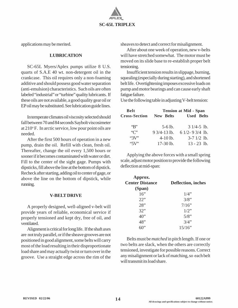
A properly designed, well-aligned v-belt willprovide years of reliable, economical service ifproperly tensioned and kept dry, free of oil, andventilated.
Alignment is critical for long life. If the shaft axesare not truly parallel, or if the sheave grooves are notpositioned in good alignment, some belts will carrymost of the load resulting in their disproportionateload share and may actually twist or turn over in thegroove. Use a straight edge across the rim of the
sheaves to detect and correct for misalignment.After about one week of operation, new v-belts
will have stretched somewhat. The motor must bemoved on its slide base to re-establish proper belttensioning.
Insufficient tension results in slippage, burning,squealing (especially during starting), and shortenedbelt life. Overtightening imposes excessive loads onpump and motor bearings and can cause early shaftfatigue failure.Use the following table in adjusting V-belt tension:
Belt Tension at Mid - SpanCross-Section New Belts Used Belts
“B” 5-6 lb. 3 1/4-5 lb.“C” 9 3/4-13 lb. 6 1/2- 9 3/4 lb.“3V” 4-10 lb. 3-7 1/2 lb.“5V” 17-30 lb. 13 - 23 lb.
Applying the above forces with a small springscale, adjust motor position to provide the followingdeflection at mid-span:
Approx. Center Distance Deflection, inches (Span) 16” 1/4” 22” 3/8” 28” 7/16” 32” 1/2” 40” 5/8” 48” 3/4” 60” 15/16”
Belts must be matched in pitch length. If one ortwo belts are slack, when the others are correctlytensioned, investigate for possible reasons. Correctany misalignment or lack of matching, so each beltwill transmit its load share.
SC-65L TRIPLEX
15 All drawings and specifications subject to change without notice. REVISED 02/22/06 60122A999
If pump is gear driven, remember that the pinionshaft turns opposite the crankshaft, if using a single-reduction geared drive or in the same direction as thecrankshaft when using a planetary gear.
AUTOMATIC (SAFETY) SHUTDOWNS
Carefully check all electric shutdown devicespresent such as crankcase oil level, dischargepressure, vibration, lubricator oil level, motorthermostat, etc.
C.D.
Sheaves must be balanced to prevent abnormalvibration. Balancing weights must NOT be removed.Type “QD” sheaves must be evenly tightened on theirtapered hubs to avoid rim wobble and severe lateralvibration. V-belts which snap and jerk will produceabnormal vibration and loads on both pump andmotor or engine.
Run the pump several minutes at full load with beltguard removed observing for uneven motion on thebelt slack side, especially.
When an old V-belt drive becomes unservice-able, replace ALL belts, not just the broken orcracked belts. Do not operate belts on sheaveshaving worn, rusted, greasy, or broken grooves.Shutoff power to driver before servicing drive or pump.
WARNING: Do not operate withoutappropiate guards in place.
DIRECTION OF ROTATION
Before placing pump in operation, check thatcrankshaft rotation agrees with the arrows cast on topof the power frame by briefly jogging the electricmotor. Crankshaft rotation must be clockwise asviewed from the right side of pump.
SC-65L TRIPLEX
16 REVISED 02/22/06 60122A999All drawings and specifications subject to change without notice.
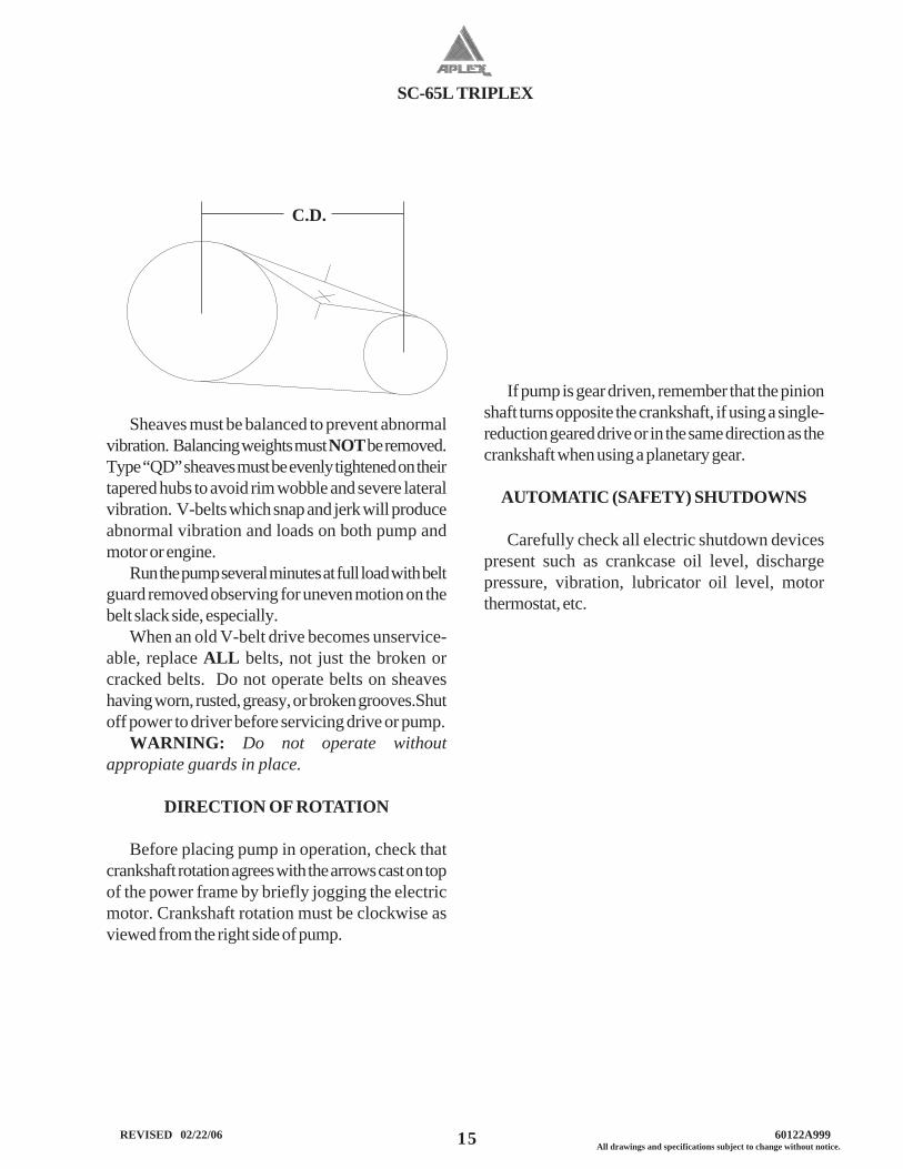
GENERAL
Myers/Aplex crankshaft suspension utilizes twosingle-row tapered bearings, which are shim adjustedto provide the correct running clearance.
Thorough cleaning of all components prior toassembly is essential.
Power frame, shaft, bearings and retainer MUSTbe scrupulously scrubbed with clean solvent (such askerosene) before starting. Remove any oil, dirt, rustand foreign matter which might prevent the correct fitup.
Crankshaft journals are critical. Remove allburrs, rust spots, and nicks, paying special attentionto the ground areas on which bearings and oil sealsoperate.
TAPERED ROLLER BEARINGS
Shaft and frame tolerances provide a tight (press)fit on the shaft, and tap fit in the frame. The best wayto install the cone assembly (consists of the inner race,cage and rollers) on the shaft is to heat the coneassembly in an electric oven for 30 minutes at 300 to400oF. No More! (Do NOT heat bearings with anacetylene torch. This ruins the bearings!) Using clean,
insulated gloves, remove the hot cone assembly fromthe oven, promptly dropping it on to the shaft.
The cone assembly MUST contact the seat thrustface (not be cocked), and the large end of the rollersMUST be down. Do not hammer on the bearing. Thesoft steel cage is easily distorted, ruining its function asa roller separator and guide against skewing. If thecone does not contact its thrust face properly, it mustbe pressed into place using a specially machinedsleeve (which does not touch the soft steel cage). Ahydraulic press is recommended if this difficultyarises.
CRANKSHAFT ASSEMBLY
SC-65L TRIPLEX
17 All drawings and specifications subject to change without notice. REVISED 02/22/06 60122A999
INSTALLING CRANKSHAFT
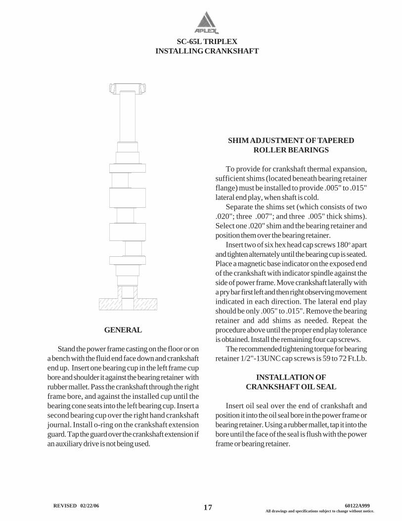
GENERAL
Stand the power frame casting on the floor or ona bench with the fluid end face down and crankshaftend up. Insert one bearing cup in the left frame cupbore and shoulder it against the bearing retainer withrubber mallet. Pass the crankshaft through the rightframe bore, and against the installed cup until thebearing cone seats into the left bearing cup. Insert asecond bearing cup over the right hand crankshaftjournal. Install o-ring on the crankshaft extensionguard. Tap the guard over the crankshaft extension ifan auxiliary drive is not being used.
SHIM ADJUSTMENT OF TAPEREDROLLER BEARINGS
To provide for crankshaft thermal expansion,sufficient shims (located beneath bearing retainerflange) must be installed to provide .005" to .015"lateral end play, when shaft is cold.
Separate the shims set (which consists of two.020"; three .007"; and three .005" thick shims).Select one .020" shim and the bearing retainer andposition them over the bearing retainer.
Insert two of six hex head cap screws 180o apartand tighten alternately until the bearing cup is seated.Place a magnetic base indicator on the exposed endof the crankshaft with indicator spindle against theside of power frame. Move crankshaft laterally witha pry bar first left and then right observing movementindicated in each direction. The lateral end playshould be only .005" to .015". Remove the bearingretainer and add shims as needed. Repeat theprocedure above until the proper end play toleranceis obtained. Install the remaining four cap screws.
The recommended tightening torque for bearingretainer 1/2"-13UNC cap screws is 59 to 72 Ft.Lb.
INSTALLATION OFCRANKSHAFT OIL SEAL
Insert oil seal over the end of crankshaft andposition it into the oil seal bore in the power frame orbearing retainer. Using a rubber mallet, tap it into thebore until the face of the seal is flush with the powerframe or bearing retainer.
SC-65L TRIPLEX
18 REVISED 02/22/06 60122A999All drawings and specifications subject to change without notice.
GENERAL
Myers/Aplex connecting rod assemblies employprecision automotive type steel-backed, babbitt-lined crankpin bearing halves which require no shimsfor clearance adjustment. This pump employs full-circle (piston type) crossheads.
Plungers are provided with a knurled wrenchingarea to permit tightening of the tapered thread into thecrosshead, establishing accurate alignment whileaffording easy field installation.
Before beginning the assembly all parts must bescrupulously cleaned, removing all oil, dirt, rust, andforeign matter which prevent proper fitting, or whichmight tend to score the rubbing surfaces. Clean andexamine the power frame bores for scoring andabnormal wear, especially wear of the lowercrosshead guide way. Hone smooth, if rough.
Measure the bores of the frame using insidemicrometers to determine abnormal frame wear ifany.
New crosshead O.D. ......... 3.996/3.993”New frame bores ............. 4.000/4.004”
Frame bores which have become worn more than.015" must be sleeved with a cast iron liner to re-establish correct geometry and alignment. Contact
CONNECTING ROD, CROSSHEAD, AND CROSSHEAD PIN ASSEMBLY:
Myers/Aplex concerning the repair of badly wornframe bores.
Smooth any rough corners and edges on thecrosshead skirts, using fine emery cloth. Examine andclean the female tapered threads and wrist pin holes.
INSTALLING WRIST PIN BUSHINGS
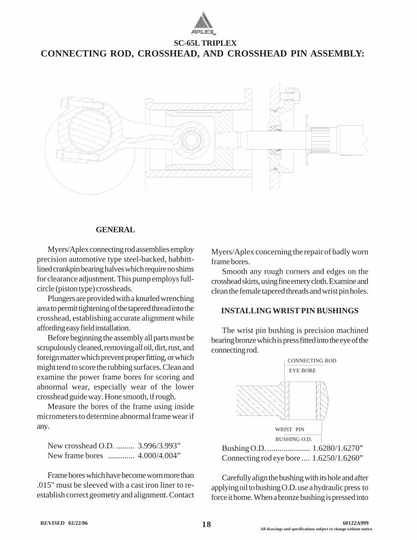
The wrist pin bushing is precision machinedbearing bronze which is press fitted into the eye of theconnecting rod.
CONNECTING ROD
EYE BORE
WRIST PIN
BUSHING O.D.
Bushing O.D. ..................... 1.6280/1.6270”Connecting rod eye bore .... 1.6250/1.6260”
Carefully align the bushing with its hole and afterapplying oil to bushing O.D. use a hydraulic press toforce it home. When a bronze bushing is pressed into
SC-65L TRIPLEX
19 All drawings and specifications subject to change without notice. REVISED 02/22/06 60122A999
place, the I.D. (bore) of the bushing is reducedsomewhat, owing to the extent of press fit. Therefore,a clean, new wrist pin should be inserted into thebushing bore to establish that running clearance hasbeen obtained. The running clearance between thewrist pin and installed bushing is:
New pin O.D. .................. 1.3140/1.3135”Installed bushing bore ....... 1.3145/1.3155”Oil Clearance ................... .0005/.0020”
Replacement bushings are furnished pre-boredby Myers/Aplex which usually eliminates the need toream the installed bushing bore. However, due toslight variations in finishes and tolerances it sometimeshappens that more than predicted contraction of theI.D. occurs. This occurrence results in a slightinterference which may be eliminated by lightly honingthe bore of the bronze. (NOT by reducing the pinsize!). An automotive engine repair shop usually isequipped with power honing machines capable ofsmoothly finishing the bushing bore. Bore of bushingmust be round and free of taper.
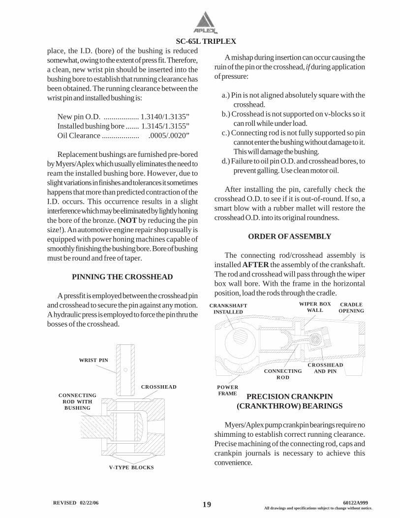
PINNING THE CROSSHEAD
A pressfit is employed between the crosshead pinand crosshead to secure the pin against any motion.A hydraulic press is employed to force the pin thru thebosses of the crosshead.
A mishap during insertion can occur causing theruin of the pin or the crosshead, if during applicationof pressure:
a.) Pin is not aligned absolutely square with thecrosshead.
b.) Crosshead is not supported on v-blocks so itcan roll while under load.
c.) Connecting rod is not fully supported so pincannot enter the bushing without damage to it.This will damage the bushing.
d.) Failure to oil pin O.D. and crosshead bores, toprevent galling. Use clean motor oil.
After installing the pin, carefully check thecrosshead O.D. to see if it is out-of-round. If so, asmart blow with a rubber mallet will restore thecrosshead O.D. into its original roundness.
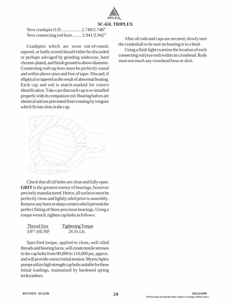
ORDER OF ASSEMBLY
The connecting rod/crosshead assembly isinstalled AFTER the assembly of the crankshaft.The rod and crosshead will pass through the wiperbox wall bore. With the frame in the horizontalposition, load the rods through the cradle.
PRECISION CRANKPIN(CRANKTHROW) BEARINGS
Myers/Aplex pump crankpin bearings require noshimming to establish correct running clearance.Precise machining of the connecting rod, caps andcrankpin journals is necessary to achieve thisconvenience.
WRIST PIN
CROSSHEAD
V-TYPE BLOCKS
CONNECTINGROD WITHBUSHING
CRANKSHAFTINSTALLED
WIPER BOXWALL
CRADLEOPENING
CROSSHEADAND PINCONNECTING
ROD
POWERFRAME
SC-65L TRIPLEX
20 REVISED 02/22/06 60122A999All drawings and specifications subject to change without notice.
New crankpin O.D. ................ 2.749/2.748”New connecting rod bore ....... 2.941/2.942”
Crankpins which are worn out-of-round,tapered, or badly scored should either be discardedor perhaps salvaged by grinding undersize, hardchrome-plated, and finish ground to above diameter.Connecting rod/cap bore must be perfectly roundand within above sizes and free of taper. Discard, ifelliptical or tapered as the result of abnormal heating.Each cap and rod is match-marked for correctidentification. Take care that each cap is re-installedproperly with its companion rod. Bearing halves areidentical and are prevented from rotating by tongueswhich fit into slots in the cap.
Check that all oil holes are clean and fully open.GRIT is the greatest enemy of bearings, howeverprecisely manufactured. Hence, all surfaces must beperfectly clean and lightly oiled prior to assembly.Remove any burrs or sharp corners which prevent theperfect fitting of these precision bearings. Using atorque wrench, tighten cap bolts as follows:
Thread Size Tightening Torque3/8”-16UNF 26 Ft.Lb.
Specified torque, applied to clean, well oiledthreads and bearing faces, will create tensile stressesin the cap bolts from 90,000 to 110,000 psi, approx.and will provide correct initial tension. Myers/Aplexpumps utilize high strength cap bolts suitable for theseinitial loadings, maintained by hardened springlockwashers.
After all rods and caps are secured, slowly turnthe crankshaft to be sure no bearing is in a bind.
Using a flash light examine the location of eachconnecting rod (eye end) within its crosshead. Rodsmust not touch any crosshead boss or skirt.
SC-65L TRIPLEX
21 All drawings and specifications subject to change without notice. REVISED 02/22/06 60122A999
WIPER BOX ASSEMBLY
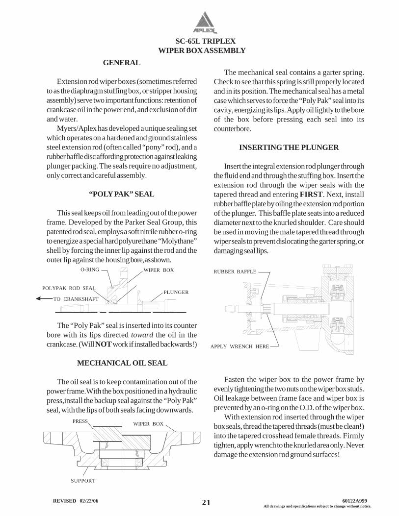
The mechanical seal contains a garter spring.Check to see that this spring is still properly locatedand in its position. The mechanical seal has a metalcase which serves to force the “Poly Pak” seal into itscavity, energizing its lips. Apply oil lightly to the boreof the box before pressing each seal into itscounterbore.
INSERTING THE PLUNGER
Insert the integral extension rod plunger throughthe fluid end and through the stuffing box. Insert theextension rod through the wiper seals with thetapered thread and entering FIRST. Next, installrubber baffle plate by oiling the extension rod portionof the plunger. This baffle plate seats into a reduceddiameter next to the knurled shoulder. Care shouldbe used in moving the male tapered thread throughwiper seals to prevent dislocating the garter spring, ordamaging seal lips.
Fasten the wiper box to the power frame byevenly tightening the two nuts on the wiper box studs.Oil leakage between frame face and wiper box isprevented by an o-ring on the O.D. of the wiper box.
With extension rod inserted through the wiperbox seals, thread the tapered threads (must be clean!)into the tapered crosshead female threads. Firmlytighten, apply wrench to the knurled area only. Neverdamage the extension rod ground surfaces!
RUBBER BAFFLE
APPLY WRENCH HERE
GENERAL
Extension rod wiper boxes (sometimes referredto as the diaphragm stuffing box, or stripper housingassembly) serve two important functions: retention ofcrankcase oil in the power end, and exclusion of dirtand water.
Myers/Aplex has developed a unique sealing setwhich operates on a hardened and ground stainlesssteel extension rod (often called “pony” rod), and arubber baffle disc affording protection against leakingplunger packing. The seals require no adjustment,only correct and careful assembly.
“POLY PAK” SEAL
This seal keeps oil from leading out of the powerframe. Developed by the Parker Seal Group, thispatented rod seal, employs a soft nitrile rubber o-ringto energize a special hard polyurethane “Molythane”shell by forcing the inner lip against the rod and theouter lip against the housing bore, as shown.
The “Poly Pak” seal is inserted into its counterbore with its lips directed toward the oil in thecrankcase. (Will NOT work if installed backwards!)
MECHANICAL OIL SEAL
The oil seal is to keep contamination out of thepower frame.With the box positioned in a hydraulicpress,install the backup seal against the “Poly Pak”seal, with the lips of both seals facing downwards.
O-RING WIPER BOX
PLUNGERPOLYPAK ROD SEAL
TO CRANKSHAFT
PRESS WIPER BOX
SUPPORT
SC-65L TRIPLEX
22 REVISED 02/22/06 60122A999All drawings and specifications subject to change without notice.
GENERAL
Myers/Aplex pumps all feature field removableand replaceable stuffing boxes. The SC-65L hasintegral extension rods. The plungers may beremoved separately (with-out box removal) tofacilitate re-packing. The integral extension rod typeplunger may be removed by removing the cylinderhead plug and retainer plate allowing the plunger to beremoved through the fluid end, after unscrewing itfrom the crosshead. It is not necessary to disturb thefluid end or piping.
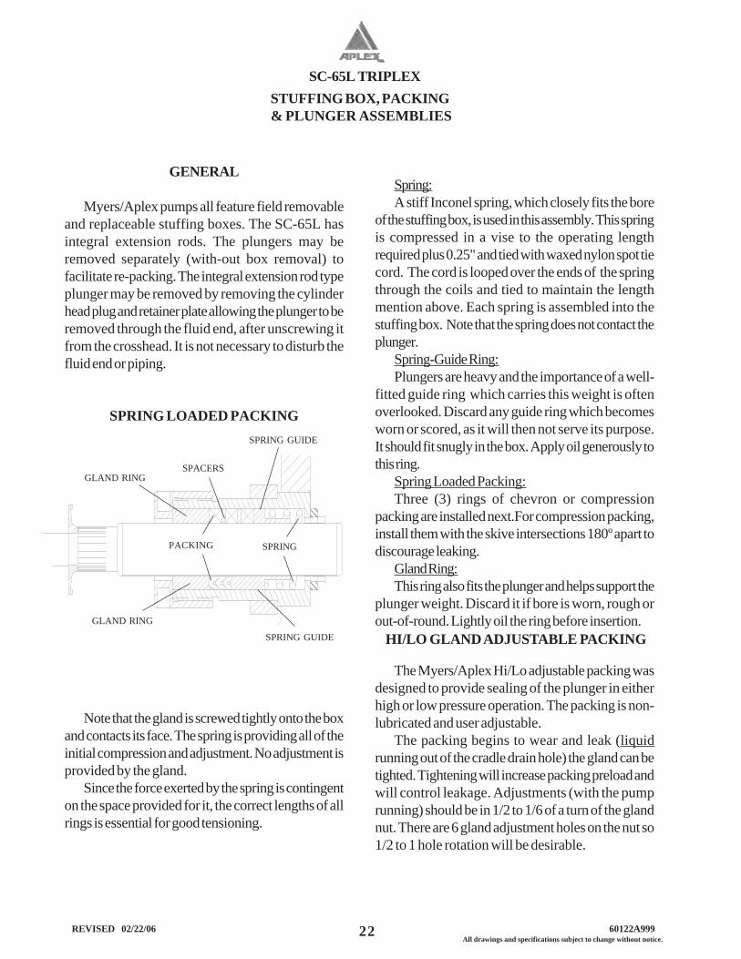
SPRING LOADED PACKING
Note that the gland is screwed tightly onto the boxand contacts its face. The spring is providing all of theinitial compression and adjustment. No adjustment isprovided by the gland.
Since the force exerted by the spring is contingenton the space provided for it, the correct lengths of allrings is essential for good tensioning.
Spring:A stiff Inconel spring, which closely fits the bore
of the stuffing box, is used in this assembly. This springis compressed in a vise to the operating lengthrequired plus 0.25" and tied with waxed nylon spot tiecord. The cord is looped over the ends of the springthrough the coils and tied to maintain the lengthmention above. Each spring is assembled into thestuffing box. Note that the spring does not contact theplunger.
Spring-Guide Ring:Plungers are heavy and the importance of a well-
fitted guide ring which carries this weight is oftenoverlooked. Discard any guide ring which becomesworn or scored, as it will then not serve its purpose.It should fit snugly in the box. Apply oil generously tothis ring.
Spring Loaded Packing:Three (3) rings of chevron or compression
packing are installed next.For compression packing,install them with the skive intersections 180º apart todiscourage leaking.
Gland Ring:This ring also fits the plunger and helps support the
plunger weight. Discard it if bore is worn, rough orout-of-round. Lightly oil the ring before insertion.
STUFFING BOX, PACKING & PLUNGER ASSEMBLIES
SPRINGPACKING
SPACERSGLAND RING
GLAND RING
SPRING GUIDE
SPRING GUIDE
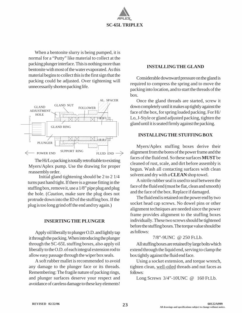
The Myers/Aplex Hi/Lo adjustable packing wasdesigned to provide sealing of the plunger in eitherhigh or low pressure operation. The packing is non-lubricated and user adjustable.
The packing begins to wear and leak (liquidrunning out of the cradle drain hole) the gland can betighted. Tightening will increase packing preload andwill control leakage. Adjustments (with the pumprunning) should be in 1/2 to 1/6 of a turn of the glandnut. There are 6 gland adjustment holes on the nut so1/2 to 1 hole rotation will be desirable.
HI/LO GLAND ADJUSTABLE PACKING
SC-65L TRIPLEX
23 All drawings and specifications subject to change without notice. REVISED 02/22/06 60122A999
All stuffing boxes are retained by large bolts whichextend through the liquid end, serving to clamp thebox tightly against the fluid end face.
Using a socket extension, and torque wrench,tighten clean, well-oiled threads and nut faces asfollows:
Long Screws 3/4”-10UNC @ 160 Ft.Lb.
INSTALLING THE GLAND
Considerable downward pressure on the gland isrequired to compress the spring and to move thepacking into location, and to start the threads of thebox.
Once the gland threads are started, screw itdown completely until it makes up tightly against theface of the box, for spring loaded packing. For Hi/Lo, J-Style or gland adjusted packing, tighten thegland until it is seated firmly against the packing.
INSTALLING THE STUFFING BOX
Myers/Aplex stuffing boxes derive theiralignment from the bores of the power frame and thefaces of the fluid end. So these surfaces MUST becleaned of rust, scale, and dirt before assembly isbegun. Wash all contacting surfaces with cleansolvent and dry with a CLEAN shop towel.
A nitrile rubber seal is used to seal between theface of the fluid end (must be flat, clean and smooth)and the face of the box. Replace if damaged.
The fluid end is retained on the power end by twosocket head cap screws. No dowel pins or otheralignment techniques are needed since the powerframe provides alignment to the stuffing boxesindividually. These two screws should be tightenedbefore the stuffing boxes. The torque value should beas follows:
7/8”-9UNC @ 250 Ft.Lb.
Initial gland tightening should be 2 to 2 1/4turns past hand tight. If there is a grease fitting in thestuffing box, remove it, use a 1/8” pipe plug and plugthe hole. (Caution, make sure the plug does notprotrude down into the ID of the stuffing box. If theplug is too long grind off the end and try again.)
When a bentonite slurry is being pumped, it isnormal for a “Putty” like material to collect at thepacking plunger interface. This is nothing more thanbentonite with most of the water evaporated. As thismaterial begins to collect this is the first sign that thepacking could be adjusted. Over tightening willunnecessarily shorten packing life.
The Hi/Lo packing is totally retrofitable to existingMyers/Aplex pump. Use the drawing for properreassembly order.
SUPPORT RING
FOLLOWER GLAND ADJUSTMENT HOLE
GLAND NUT
GLAND RING
AL. SPACER
POWER END FLUID END
PLUNGER
INSERTING THE PLUNGER
Apply oil liberally to plunger O.D. and lightly tapit through the packing. When introducing the plungerthrough the SC-65L stuffing boxes, also apply oilliberally to the O.D. of each integral extension rod toallow easy passage through the wiper box seals.
A soft rubber mallet is recommended to avoidany damage to the plunger face or its threads.Remembering: The fragile nature of packing rings,and plunger surfaces deserve your respect andavoidance of careless damage to these key elements!
SC-65L TRIPLEX
24 REVISED 02/22/06 60122A999All drawings and specifications subject to change without notice.
A good start is to use steam cylinder oil. Castoroil is sometimes successful as a packing lubricationfor liquid propane and butane services, at ambienttemperature.
In pumps placed in arctic service, a special lowpour point oil is indicated.
Packing lubrication is not permitted on someservices, such an amine, food stuffs, etc. and otherpacking styles and materials may be required.
PLUNGERS
Myers/Aplex offers its own unique product: theMyers/Aplex “Rokide” plunger. This premier qualityplunger consists of a chromium-oxide deposition ona solid stainless steel body.
Ordinary handling will not damage this fineproduct. Avoid striking the coated surface(black)during installation. Apply light forces only on the endsof the plunger. Do not hammer or pry.
All threads on Myers/Aplex plungers must beCLEAN and oiled before assembly. Stain-less steel (although very corrosion resistant) has atendency to gall and seize. To avoid this, an anti-seizing lubricant is well worth its use. Apply oil to thethreads.
Myers/Aplex can supply solid ceramic plungerson order. This plunger is very fragile, vulnerable tothermal and mechanical shock, and must be handledwith the greatest care. Use only a rubber mallet toinsert it into the packing. Other plunger types areavailable upon request.
CONNECTING THE PLUNGER
Install the rubber baffle on to the integral extensionrod, sliding it against the knurled shoulder of theplunger. Roll the pump crankshaft slowly until theplunger male threads touch the mating female threadsin the crosshead.
Applying a pipe wrench to plunger knurled area,thoroughly tighten the connection. Do NOT use a“cheater” when connecting plunger to extension rod.(Serves no useful purpose, and may damage theconnection!)
PACKING
Packing life for Aramid fiber packing may beimproved, in some applications by regular,systematic lubrication. An optional force feedlubricator assembly is often recommended especiallyfor pumps on continuous duty. This provides regular,controlled supply of lubricant lowering friction andheat.
Additionally, the regular application of the correctlubricant aids dissolving of salt and gyp tending tobuild up on the plungers in produced waterapplications. For this service, Rock Drill Lubricant isa popular and effective packing lubricant.
Packing lubricant for pumps on light hydrocar-bons, hot water, lean oil, naphtha, or gasoline oftenrequire experimentation.
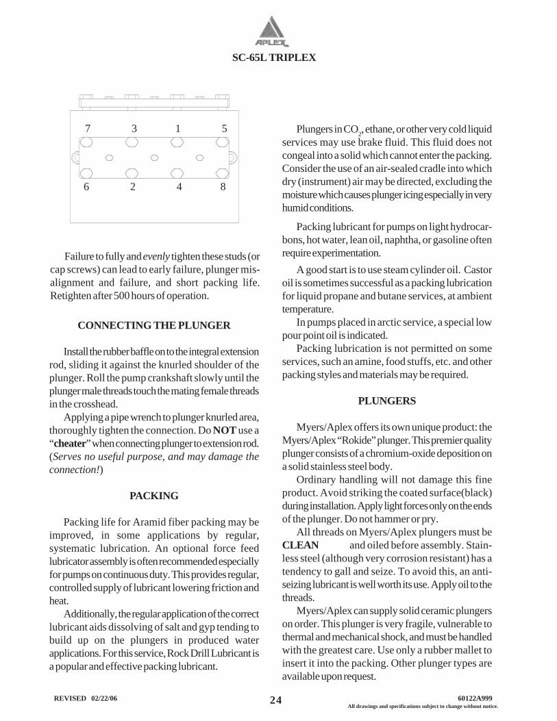
7 3 1 5
6 2 4 8
Plungers in CO2, ethane, or other very cold liquidservices may use brake fluid. This fluid does notcongeal into a solid which cannot enter the packing.Consider the use of an air-sealed cradle into whichdry (instrument) air may be directed, excluding themoisture which causes plunger icing especially in veryhumid conditions.
Failure to fully and evenly tighten these studs (orcap screws) can lead to early failure, plunger mis-alignment and failure, and short packing life.Retighten after 500 hours of operation.
SC-65L TRIPLEX
25 All drawings and specifications subject to change without notice. REVISED 02/22/06 60122A999
GENERAL
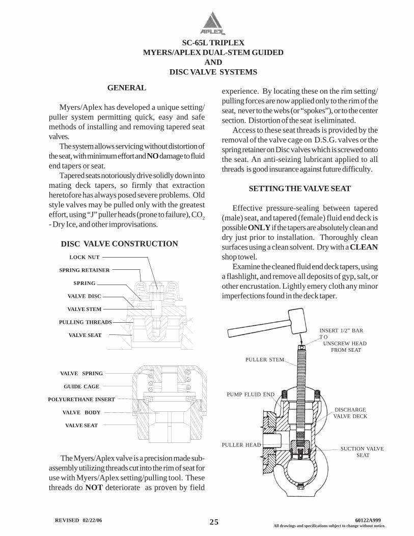
Myers/Aplex has developed a unique setting/puller system permitting quick, easy and safemethods of installing and removing tapered seatvalves.
The system allows servicing without distortion ofthe seat, with minimum effort and NO damage to fluidend tapers or seat.
Tapered seats notoriously drive solidly down intomating deck tapers, so firmly that extractionheretofore has always posed severe problems. Oldstyle valves may be pulled only with the greatesteffort, using “J” puller heads (prone to failure), CO2- Dry Ice, and other improvisations.
VALVE CONSTRUCTION
The Myers/Aplex valve is a precision made sub-assembly utilizing threads cut into the rim of seat foruse with Myers/Aplex setting/pulling tool. Thesethreads do NOT deteriorate as proven by field
LOCK NUT
SPRING RETAINER
SPRING
VALVE DISC
VALVE STEM
PULLING THREADS
VALVE SEAT
experience. By locating these on the rim setting/pulling forces are now applied only to the rim of theseat, never to the webs (or “spokes”), or to the centersection. Distortion of the seat is eliminated.
Access to these seat threads is provided by theremoval of the valve cage on D.S.G. valves or thespring retainer on Disc valves which is screwed ontothe seat. An anti-seizing lubricant applied to allthreads is good insurance against future difficulty.
SETTING THE VALVE SEAT
Effective pressure-sealing between tapered(male) seat, and tapered (female) fluid end deck ispossible ONLY if the tapers are absolutely clean anddry just prior to installation. Thoroughly cleansurfaces using a clean solvent. Dry with a CLEANshop towel.
Examine the cleaned fluid end deck tapers, usinga flashlight, and remove all deposits of gyp, salt, orother encrustation. Lightly emery cloth any minorimperfections found in the deck taper.
MYERS/APLEX DUAL-STEM GUIDEDAND
DISC VALVE SYSTEMS
DISC
VALVE SPRING
GUIDE CAGE
POLYURETHANE INSERT
VALVE BODY
VALVE SEAT
INSERT 1/2” BART O UNSCREW HEAD FROM SEAT
PULLER STEM
PUMP FLUID END
PULLER HEAD
DISCHARGEVALVE DECK
SUCTION VALVE SEAT
SC-65L TRIPLEX
26 REVISED 02/22/06 60122A999All drawings and specifications subject to change without notice.
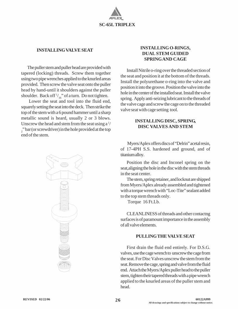
Position the disc and Inconel spring on theseat,aligning the hole in the disc with the stem threadsin the seat center.
The stem, spring retainer, and locknut are shippedfrom Myers/Aplex already assembled and tightenedwith a torque wrench with “Loc-Tite” sealant addedto the top stem threads only.
Torque 16 Ft.Lb.
INSTALLING O-RINGS,DUAL STEM GUIDEDSPRING AND CAGE
Install Nitrile o-ring over the threaded section ofthe seat and position it at the bottom of the threads.Install the polyurethane o-ring into the valve andposition it into the groove. Position the valve into thehole in the center of the installed seat. Install the valvespring. Apply anti-seizing lubricant to the threads ofthe valve cage and screw the cage on to the threadedvalve seat with cage setting tool.
INSTALLING DISC, SPRING,DISC VALVES AND STEM
Myers/Aplex offers discs of “Delrin” acetal resin,of 17-4PH S.S. hardened and ground, and oftitanium alloy.
INSTALLING VALVE SEAT
The puller stem and puller head are provided withtapered (locking) threads. Screw them togetherusing two pipe wrenches applied to the knurled areasprovided. Then screw the valve seat onto the pullerhead by hand-until it shoulders against the pullershoulder. Back off 1/16” of a turn. Do not tighten.
Lower the seat and tool into the fluid end,squarely setting the seat into the deck. Then strike thetop of the stem with a 6 pound hammer until a sharpmetallic sound is heard, usually 2 or 3 blows.Unscrew the head and stem from the seat using a 1/2” bar (or screwdriver) in the hole provided at the topend of the stem.
CLEANLINESS of threads and other contactngsurfaces is of paramount importance in the assemblyof all valve elements.
PULLING THE VALVE SEAT
First drain the fluid end entirely. For D.S.G.valves, use the cage wrench to unscrew the cage fromthe seat. For Disc Valves unscrew the stem from theseat. Remove the cage, spring and valve from the fluidend. Attach the Myers/Aplex puller head to the pullerstem, tighten their tapered threads with a pipe wrenchapplied to the knurled areas of the puller stem andhead.
SC-65L TRIPLEX
27 All drawings and specifications subject to change without notice. REVISED 02/22/06 60122A999
Lower the stem and head into the fluid end andengage the threads of the head onto the seat threads.Using a 1/2” bar (or screwdriver) rotate the headclockwise, thread it fully onto the seat. But, do NOTtighten.
REMOVING VALVE SEAT
Slide the bridge over the stem. Clean and oil thestem threads. Oil the face of the wing nut. Threadwing nut down onto the stem, seating it on the bridgetop firmly. Extract the seat from the pump by strikingthe wing nut with a heavy hammer. A hydraulic rammay also be used. Stand clear of the pump whenapplying heavy tonnage, as the entire assembly willjump violently upwards when the pulling energy issuddenly released!
The Myers/Aplex puller/setting tool and gage toolare custom designed and built for each specificMyers/Aplex pump model. The same puller head isused on both suction and discharge seats. The bridgeis made to fit each model and its proper use will notdamage the valve cover gasket machined counterboreon the top of the fluid end.
SC-65L TRIPLEX
28 REVISED 02/22/06 60122A999All drawings and specifications subject to change without notice.
Trouble
Pump fails to deliver requiredcapacity.
Possible Cause
Speed incorrect.Belts slipping.
Air leaking into pump.
Liquid cylinder valves,seats or plungers worn.
Insufficient NPSHA.
Pump not filling.
Makeup in suction tank less thandisplacement of pump.
Vortex in supply tank.
One or more cylindersnot pumping.
Suction lift too great.
Broken valve springs.
Stuck foot valve.
Pump valve stuck open.
Clogged suction strainer.
Relief, bypass, pressure valvesleaking.
Remedy
Change drive ratio or tightenbelts (if loose). Correct motorspeed.
Seal with compounds.
Reface or lap valves and seats;replace packing or plungers.
Increase suction pressure.
Prime pump.
Increase makeup flow.Reduce pump speed.
Increased liquid level in supplytank. Install vortex breaker.
Prime all cylinders. Allow pumpto operate at low pressurethrough bypass valve to eliminatevapor.
Decrease lift. Raise tank level.
Replace.
Clean.
Remove debris beneath valve.
Clean or remove.
Repair.
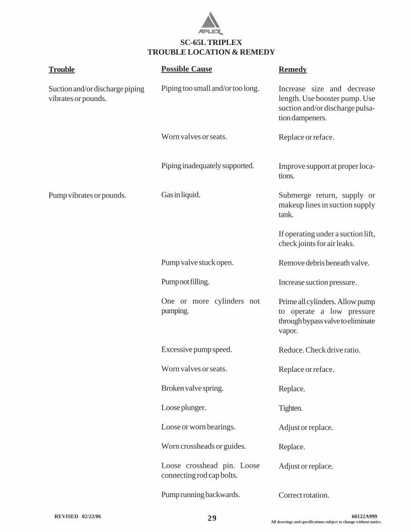
TROUBLE LOCATION & REMEDY
SC-65L TRIPLEX
29 All drawings and specifications subject to change without notice. REVISED 02/22/06 60122A999
Trouble
Suction and/or discharge pipingvibrates or pounds.
Pump vibrates or pounds.
Possible Cause
Piping too small and/or too long.
Worn valves or seats.
Piping inadequately supported.
Gas in liquid.
Pump valve stuck open.
Pump not filling.
One or more cylinders notpumping.
Excessive pump speed.
Worn valves or seats.
Broken valve spring.
Loose plunger.
Loose or worn bearings.
Worn crossheads or guides.
Loose crosshead pin. Looseconnecting rod cap bolts.
Pump running backwards.
Remedy
Increase size and decreaselength. Use booster pump. Usesuction and/or discharge pulsa-tion dampeners.
Replace or reface.
Improve support at proper loca-tions.
Submerge return, supply ormakeup lines in suction supplytank.
If operating under a suction lift,check joints for air leaks.
Remove debris beneath valve.
Increase suction pressure.
Prime all cylinders. Allow pumpto operate a low pressurethrough bypass valve to eliminatevapor.
Reduce. Check drive ratio.
Replace or reface.
Replace.
Tighten.
Adjust or replace.
Replace.
Adjust or replace.
Correct rotation.
TROUBLE LOCATION & REMEDY
SC-65L TRIPLEX
30 REVISED 02/22/06 60122A999All drawings and specifications subject to change without notice.
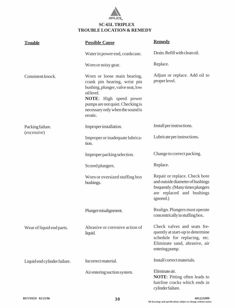
Trouble
Consistent knock.
Packing failure.(excessive)
Wear of liquid end parts.
Liquid end cylinder failure.
Possible Cause
Water in power end, crankcase.
Worn or noisy gear.
Worn or loose main bearing,crank pin bearing, wrist pinbushing, plunger, valve seat, lowoil level.NOTE: High speed powerpumps are not quiet. Checking isnecessary only when the sound iserratic.
Improper installation.
Improper or inadequate lubrica-tion.
Improper packing selection.
Scored plungers.
Worn or oversized stuffing boxbushings.
Plunger misalignment.
Abrasive or corrosive action ofliquid.
Incorrect material.
Air entering suction system.
TROUBLE LOCATION & REMEDY
Remedy
Drain. Refill with clean oil.
Replace.
Adjust or replace. Add oil toproper level.
Install per instructions.
Lubricate per instructions.
Change to correct packing.
Replace.
Repair or replace. Check boreand outside diameter of bushingsfrequently. (Many times plungersare replaced and bushingsignored.)
Realign. Plungers must operateconcentrically in stuffing box.
Check valves and seats fre-quently at start-up to determineschedule for replacing, etc.Eliminate sand, abrasive, airentering pump.
Install correct materials.
Eliminate air.NOTE: Pitting often leads tohairline cracks which ends incylinder failure.
SC-65L TRIPLEX
31 All drawings and specifications subject to change without notice. REVISED 02/22/06 60122A999
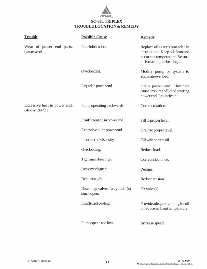
Possible Cause
Poor lubrication.
Overloading.
Liquid in power end.
Pump operating backwards.
Insufficient oil in power end.
Excessive oil in power end.
Incorrect oil viscosity.
Overloading.
Tight main bearings.
Drive misaligned.
Belts too tight.
Discharge valve of a cylinder(s)stuck open.
Insufficient cooling.
Pump speed too low.
Remedy
Replace oil as recommended ininstructions. Keep oil clean andat correct temperature. Be sureoil is reaching all bearings.
Modify pump or system toeliminate overload.
Drain power end. Eliminatecause or source of liquid enteringpower end. Relubricate.
Correct rotation.
Fill to proper level.
Drain to proper level.
Fill with correct oil.
Reduce load.
Correct clearance.
Realign.
Reduce tension.
Fix valve(s).
Provide adequate cooling for oilor reduce ambient temperature.
Increase speed.
Trouble
Wear of power end parts.(excessive)
Excessive heat in power end.(Above 180oF)
TROUBLE LOCATION & REMEDY
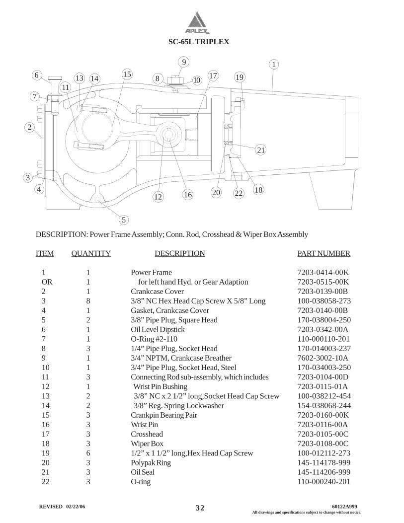
SC-65L TRIPLEX
32 REVISED 02/22/06 60122A999All drawings and specifications subject to change without notice.
DESCRIPTION: Power Frame Assembly; Conn. Rod, Crosshead & Wiper Box Assembly
ITEM QUANTITY DESCRIPTION PART NUMBER
1 1 Power Frame 7203-0414-00KOR 1 for left hand Hyd. or Gear Adaption 7203-0515-00K2 1 Crankcase Cover 7203-0139-00B3 8 3/8” NC Hex Head Cap Screw X 5/8” Long 100-038058-2734 1 Gasket, Crankcase Cover 7203-0140-00B5 2 3/8” Pipe Plug, Square Head 170-038004-2506 1 Oil Level Dipstick 7203-0342-00A7 1 O-Ring #2-110 110-000110-2018 3 1/4” Pipe Plug, Socket Head 170-014003-2379 1 3/4” NPTM, Crankcase Breather 7602-3002-10A10 1 3/4” Pipe Plug, Socket Head, Steel 170-034003-25011 3 Connecting Rod sub-assembly, which includes 7203-0104-00D12 1 Wrist Pin Bushing 7203-0115-01A13 2 3/8” NC x 2 1/2” long,Socket Head Cap Screw 100-038212-45414 2 3/8” Reg. Spring Lockwasher 154-038068-24415 3 Crankpin Bearing Pair 7203-0160-00K16 3 Wrist Pin 7203-0116-00A17 3 Crosshead 7203-0105-00C18 3 Wiper Box 7203-0108-00C19 6 1/2” x 1 1/2” long,Hex Head Cap Screw 100-012112-27320 3 Polypak Ring 145-114178-99921 3 Oil Seal 145-114206-99922 3 O-ring 110-000240-201
1113 14 15
12
17 19 1
16 20 22 18
21
2
3 4
5
6
7
10 8
9
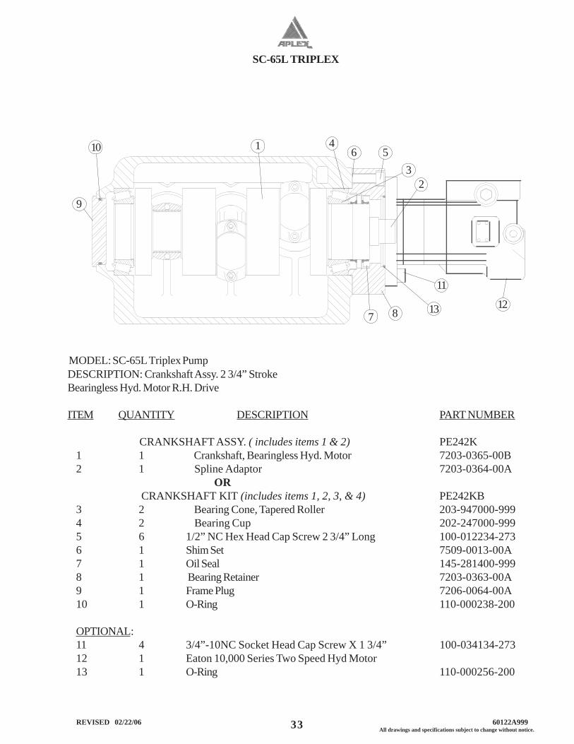
SC-65L TRIPLEX
33 All drawings and specifications subject to change without notice. REVISED 02/22/06 60122A999
MODEL: SC-65L Triplex PumpDESCRIPTION: Crankshaft Assy. 2 3/4” StrokeBearingless Hyd. Motor R.H. Drive
ITEM QUANTITY DESCRIPTION PART NUMBER
CRANKSHAFT ASSY. ( includes items 1 & 2) PE242K1 1 Crankshaft, Bearingless Hyd. Motor 7203-0365-00B2 1 Spline Adaptor 7203-0364-00A
OR CRANKSHAFT KIT (includes items 1, 2, 3, & 4) PE242KB3 2 Bearing Cone, Tapered Roller 203-947000-9994 2 Bearing Cup 202-247000-9995 6 1/2” NC Hex Head Cap Screw 2 3/4” Long 100-012234-2736 1 Shim Set 7509-0013-00A7 1 Oil Seal 145-281400-9998 1 Bearing Retainer 7203-0363-00A9 1 Frame Plug 7206-0064-00A10 1 O-Ring 110-000238-200
OPTIONAL:11 4 3/4”-10NC Socket Head Cap Screw X 1 3/4” 100-034134-27312 1 Eaton 10,000 Series Two Speed Hyd Motor13 1 O-Ring 110-000256-200
9
4 1 5 6
7 8
10
2 3
12
11
13
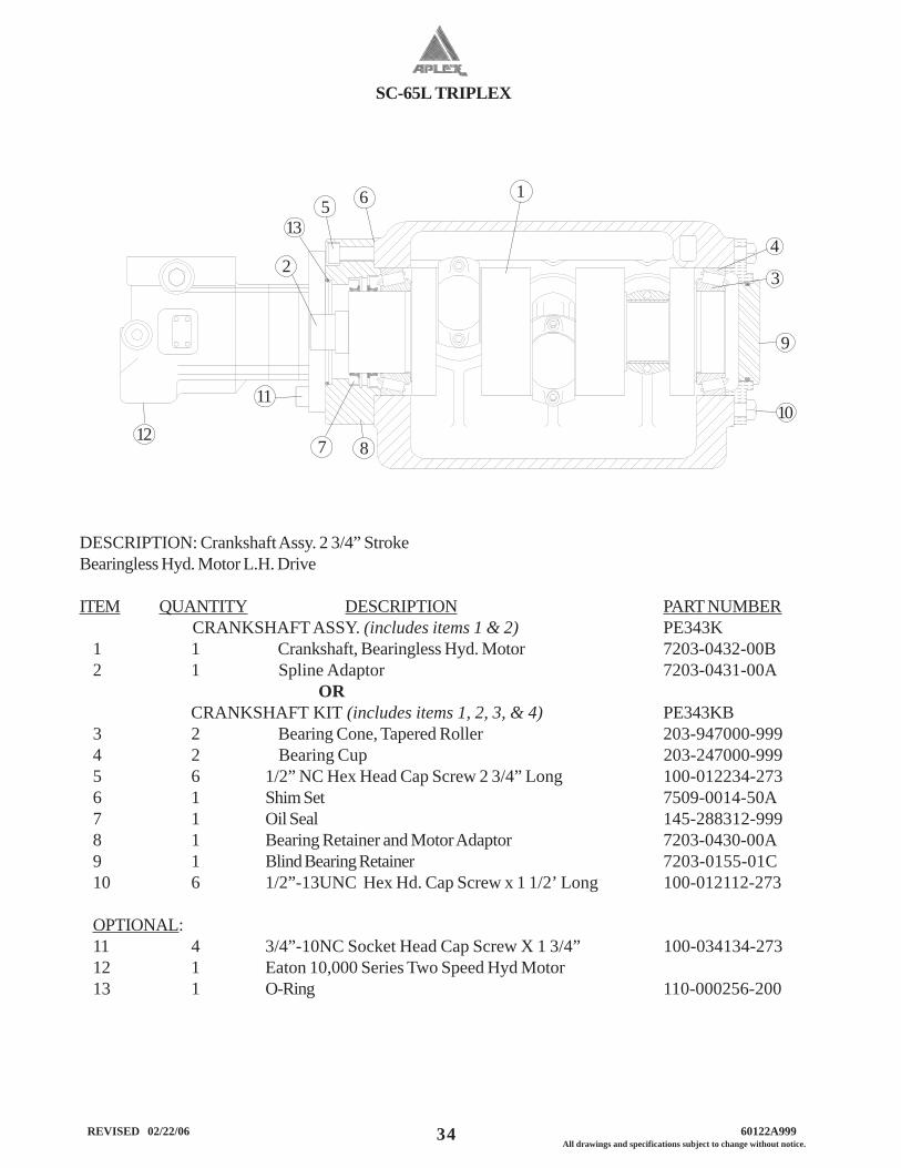
SC-65L TRIPLEX
34 REVISED 02/22/06 60122A999All drawings and specifications subject to change without notice.
DESCRIPTION: Crankshaft Assy. 2 3/4” StrokeBearingless Hyd. Motor L.H. Drive
ITEM QUANTITY DESCRIPTION PART NUMBERCRANKSHAFT ASSY. (includes items 1 & 2) PE343K
1 1 Crankshaft, Bearingless Hyd. Motor 7203-0432-00B2 1 Spline Adaptor 7203-0431-00A
OR CRANKSHAFT KIT (includes items 1, 2, 3, & 4) PE343KB3 2 Bearing Cone, Tapered Roller 203-947000-9994 2 Bearing Cup 203-247000-9995 6 1/2” NC Hex Head Cap Screw 2 3/4” Long 100-012234-2736 1 Shim Set 7509-0014-50A7 1 Oil Seal 145-288312-9998 1 Bearing Retainer and Motor Adaptor 7203-0430-00A9 1 Blind Bearing Retainer 7203-0155-01C10 6 1/2”-13UNC Hex Hd. Cap Screw x 1 1/2’ Long 100-012112-273
OPTIONAL:11 4 3/4”-10NC Socket Head Cap Screw X 1 3/4” 100-034134-27312 1 Eaton 10,000 Series Two Speed Hyd Motor13 1 O-Ring 110-000256-200
5
11
9
10
13
7 8 12
1
3 2
4
6
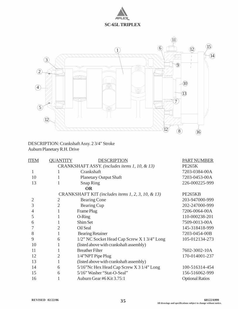
SC-65L TRIPLEX
35 All drawings and specifications subject to change without notice. REVISED 02/22/06 60122A999
DESCRIPTION: Crankshaft Assy. 2 3/4" StrokeAuburn Planetary R.H. Drive
ITEM QUANTITY DESCRIPTION PART NUMBERCRANKSHAFT ASSY. (includes items 1, 10, & 13) PE265K
1 1 Crankshaft 7203-0384-00A10 1 Planetary Output Shaft 7203-0453-00A13 1 Snap Ring 226-000225-999
OR CRANKSHAFT KIT (includes items 1, 2, 3, 10, & 13) PE265KB2 2 Bearing Cone 203-947000-9993 2 Bearing Cup 202-247000-9994 1 Frame Plug 7206-0064-00A5 1 O-Ring 110-000238-2016 1 Shim Set 7509-0013-00A7 2 Oil Seal 145-318418-9998 1 Bearing Retainer 7203-0454-00B9 6 1/2” NC Socket Head Cap Screw X 1 3/4” Long 105-012134-27310 1 (listed above with crankshaft assembly)11 1 Breather Filter 7602-3002-10A12 2 1/4”NPT Pipe Plug 170-014001-23713 1 (listed above with crankshaft assembly)14 6 5/16”Nc Hex Head Cap Screw X 3 1/4” Long 100-516314-45415 6 5/16” Washer “Stat-O-Seal” 156-516062-99916 1 Auburn Gear #6 Kit 3.75:1 Optional Ratios
15
14
5
12
11
9
10
13
7
16 8
12
1
3
2
4
12
6
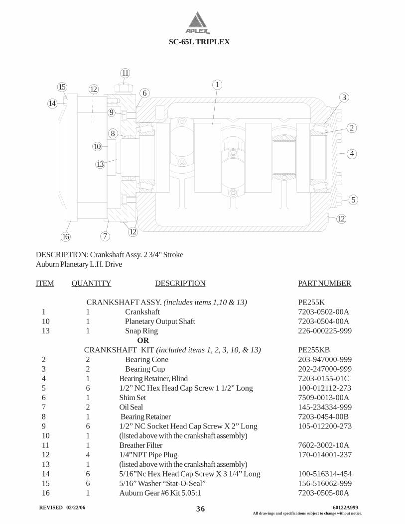
SC-65L TRIPLEX
36 REVISED 02/22/06 60122A999All drawings and specifications subject to change without notice.
DESCRIPTION: Crankshaft Assy. 2 3/4" StrokeAuburn Planetary L.H. Drive
ITEM QUANTITY DESCRIPTION PART NUMBER
CRANKSHAFT ASSY. (includes items 1,10 & 13) PE255K1 1 Crankshaft 7203-0502-00A10 1 Planetary Output Shaft 7203-0504-00A13 1 Snap Ring 226-000225-999
OR CRANKSHAFT KIT (included items 1, 2, 3, 10, & 13) PE255KB2 2 Bearing Cone 203-947000-9993 2 Bearing Cup 202-247000-9994 1 Bearing Retainer, Blind 7203-0155-01C5 6 1/2” NC Hex Head Cap Screw 1 1/2” Long 100-012112-2736 1 Shim Set 7509-0013-00A7 2 Oil Seal 145-234334-9998 1 Bearing Retainer 7203-0454-00B9 6 1/2” NC Socket Head Cap Screw X 2” Long 105-012200-27310 1 (listed above with the crankshaft assembly)11 1 Breather Filter 7602-3002-10A12 4 1/4”NPT Pipe Plug 170-014001-23713 1 (listed above with the crankshaft assembly)14 6 5/16”Nc Hex Head Cap Screw X 3 1/4” Long 100-516314-45415 6 5/16” Washer “Stat-O-Seal” 156-516062-99916 1 Auburn Gear #6 Kit 5.05:1 7203-0505-00A
15
14
5
12
11
9
10
13
7 16
8
12 1 3
2
4
12
6
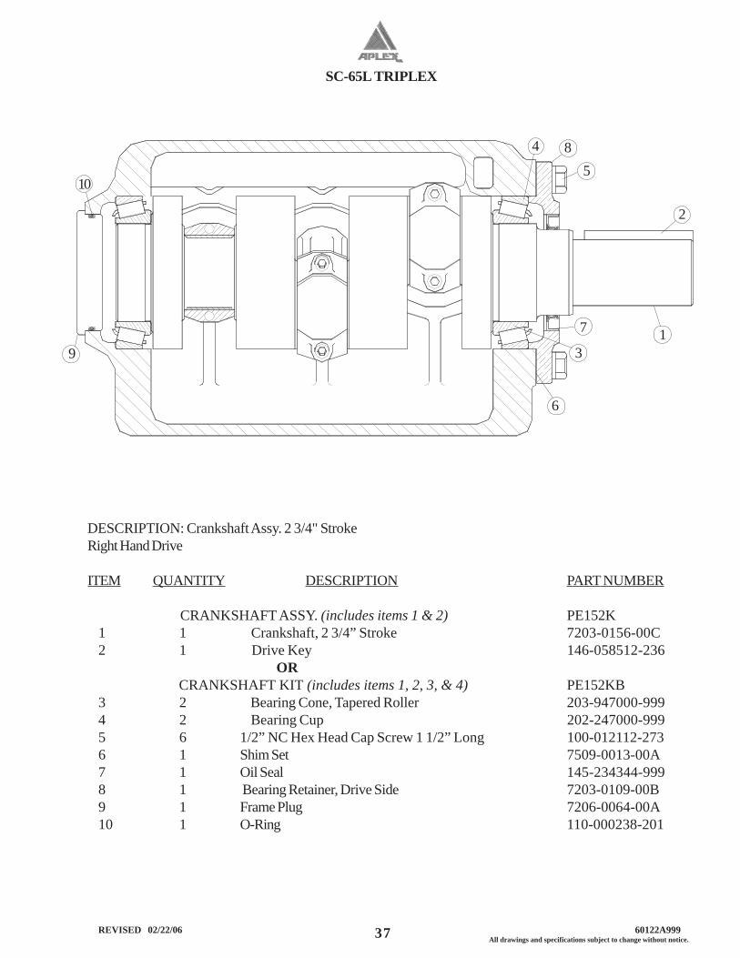
SC-65L TRIPLEX
37 All drawings and specifications subject to change without notice. REVISED 02/22/06 60122A999
DESCRIPTION: Crankshaft Assy. 2 3/4" StrokeRight Hand Drive
ITEM QUANTITY DESCRIPTION PART NUMBER
CRANKSHAFT ASSY. (includes items 1 & 2) PE152K1 1 Crankshaft, 2 3/4” Stroke 7203-0156-00C2 1 Drive Key 146-058512-236
OR CRANKSHAFT KIT (includes items 1, 2, 3, & 4) PE152KB3 2 Bearing Cone, Tapered Roller 203-947000-9994 2 Bearing Cup 202-247000-9995 6 1/2” NC Hex Head Cap Screw 1 1/2” Long 100-012112-2736 1 Shim Set 7509-0013-00A7 1 Oil Seal 145-234344-9998 1 Bearing Retainer, Drive Side 7203-0109-00B9 1 Frame Plug 7206-0064-00A10 1 O-Ring 110-000238-201
4
1
5
6
7
10
2
3 9
8
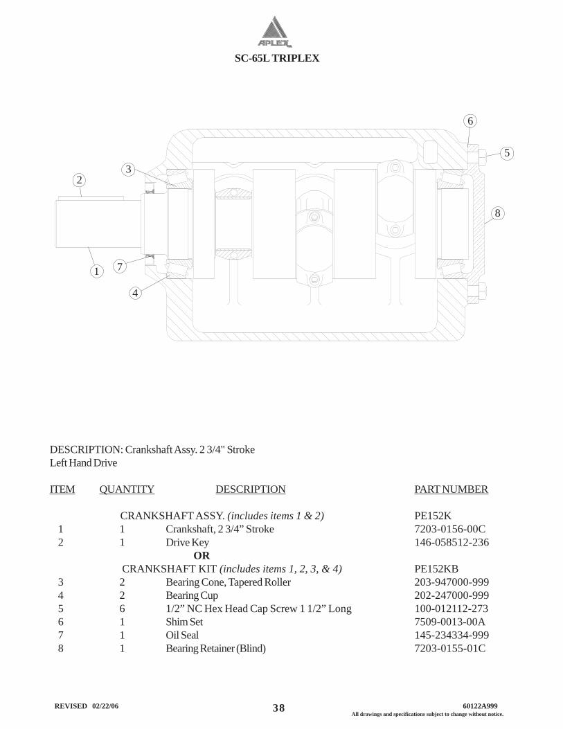
SC-65L TRIPLEX
38 REVISED 02/22/06 60122A999All drawings and specifications subject to change without notice.
DESCRIPTION: Crankshaft Assy. 2 3/4" StrokeLeft Hand Drive
ITEM QUANTITY DESCRIPTION PART NUMBER
CRANKSHAFT ASSY. (includes items 1 & 2) PE152K1 1 Crankshaft, 2 3/4” Stroke 7203-0156-00C2 1 Drive Key 146-058512-236
OR CRANKSHAFT KIT (includes items 1, 2, 3, & 4) PE152KB3 2 Bearing Cone, Tapered Roller 203-947000-9994 2 Bearing Cup 202-247000-9995 6 1/2” NC Hex Head Cap Screw 1 1/2” Long 100-012112-2736 1 Shim Set 7509-0013-00A7 1 Oil Seal 145-234334-9998 1 Bearing Retainer (Blind) 7203-0155-01C
4
1
5
6
7
2 3
8
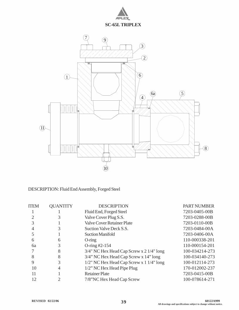
SC-65L TRIPLEX
39 All drawings and specifications subject to change without notice. REVISED 02/22/06 60122A999
DESCRIPTION: Fluid End Assembly, Forged Steel
ITEM QUANTITY DESCRIPTION PART NUMBER1 1 Fluid End, Forged Steel 7203-0405-00B2 3 Valve Cover Plug S.S. 7203-0288-00B3 1 Valve Cover Retainer Plate 7203-0110-00B4 3 Suction Valve Deck S.S. 7203-0484-00A5 1 Suction Manifold 7203-0406-00A6 6 O-ring 110-000338-2016a 3 O-ring #2-154 110-000154-2017 8 3/4" NC Hex Head Cap Screw x 2 1/4" long 100-034214-2738 8 3/4” NC Hex Head Cap Screw x 14” long 100-034140-2739 3 1/2" NC Hex Head Cap Screw x 1 1/4" long 100-012114-27310 4 1/2” NC Hex Head Pipe Plug 170-012002-23711 1 Retainer Plate 7203-0415-00B12 2 7/8”NC Hex Head Cap Screw 100-078614-271
5
11
3
2
4
8
10
1 6
7
6a
9
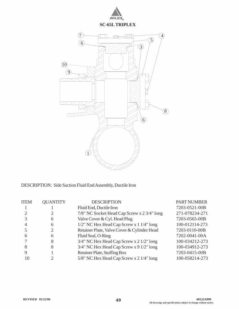
SC-65L TRIPLEX
40 REVISED 02/22/06 60122A999All drawings and specifications subject to change without notice.
1
6
8
9
3 5
6
DESCRIPTION: Side Suction Fluid End Assembly, Ductile Iron
ITEM QUANTITY DESCRIPTION PART NUMBER1 1 Fluid End, Ductile Iron 7203-0521-00B2 2 7/8" NC Socket Head Cap Screw x 2 3/4" long 271-078234-2713 6 Valve Cover & Cyl. Head Plug 7203-0565-00B4 6 1/2" NC Hex Head Cap Screw x 1 1/4" long 100-012114-2735 2 Retainer Plate, Valve Cover & Cylinder Head 7203-0110-00B6 6 Fluid Seal, O-Ring 7202-0041-00A7 8 3/4" NC Hex Head Cap Screw x 2 1/2" long 100-034212-2738 8 3/4" NC Hex Head Cap Screw x 9 1/2" long 100-034912-2739 1 Retainer Plate, Stuffing Box 7203-0415-00B10 2 5/8" NC Hex Head Cap Screw x 2 1/4" long 100-058214-273
7
10
4
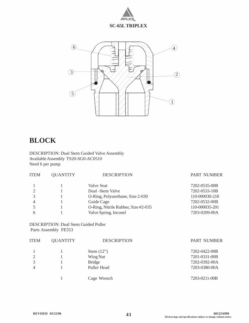
SC-65L TRIPLEX
41 All drawings and specifications subject to change without notice. REVISED 02/22/06 60122A999
BLOCKDESCRIPTION: Dual Stem Guided Valve AssemblyAvailable Assembly TS20-SG0-AC0510Need 6 per pump
ITEM QUANTITY DESCRIPTION PART NUMBER
1 1 Valve Seat 7202-0535-00B2 1 Dual -Stem Valve 7202-0533-10B3 1 O-Ring, Polyurethane, Size 2-030 110-000030-2184 1 Guide Cage 7202-0532-00B5 1 O-Ring, Nitrile Rubber, Size #2-035 110-000035-2016 1 Valve Spring, Inconel 7203-0209-00A
DESCRIPTION: Dual Stem Guided Puller Parts Assembly FE553
ITEM QUANTITY DESCRIPTION PART NUMBER
1 1 Stem (12”) 7202-0422-00B2 1 Wing Nut 7201-0331-00B3 1 Bridge 7202-0392-00A4 1 Puller Head 7203-0380-00A
1 Cage Wrench 7203-0211-00B
6
5
3
4
2
1
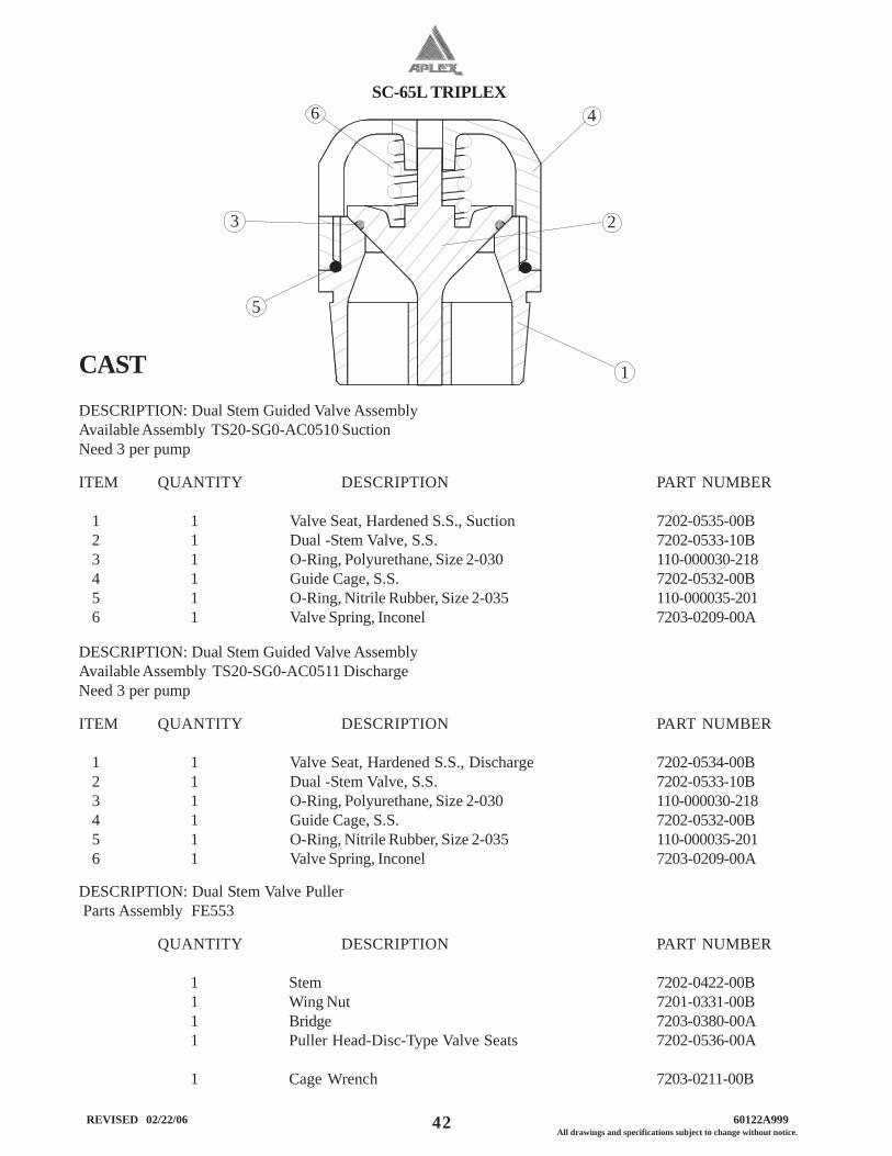
SC-65L TRIPLEX
42 REVISED 02/22/06 60122A999All drawings and specifications subject to change without notice.
CASTDESCRIPTION: Dual Stem Guided Valve AssemblyAvailable Assembly TS20-SG0-AC0510 SuctionNeed 3 per pump
ITEM QUANTITY DESCRIPTION PART NUMBER
1 1 Valve Seat, Hardened S.S., Suction 7202-0535-00B2 1 Dual -Stem Valve, S.S. 7202-0533-10B3 1 O-Ring, Polyurethane, Size 2-030 110-000030-2184 1 Guide Cage, S.S. 7202-0532-00B5 1 O-Ring, Nitrile Rubber, Size 2-035 110-000035-2016 1 Valve Spring, Inconel 7203-0209-00A
DESCRIPTION: Dual Stem Valve Puller Parts Assembly FE553
QUANTITY DESCRIPTION PART NUMBER
1 Stem 7202-0422-00B1 Wing Nut 7201-0331-00B1 Bridge 7203-0380-00A1 Puller Head-Disc-Type Valve Seats 7202-0536-00A
1 Cage Wrench 7203-0211-00B
6
5
3
4
2
1
DESCRIPTION: Dual Stem Guided Valve AssemblyAvailable Assembly TS20-SG0-AC0511 DischargeNeed 3 per pump
ITEM QUANTITY DESCRIPTION PART NUMBER
1 1 Valve Seat, Hardened S.S., Discharge 7202-0534-00B2 1 Dual -Stem Valve, S.S. 7202-0533-10B3 1 O-Ring, Polyurethane, Size 2-030 110-000030-2184 1 Guide Cage, S.S. 7202-0532-00B5 1 O-Ring, Nitrile Rubber, Size 2-035 110-000035-2016 1 Valve Spring, Inconel 7203-0209-00A
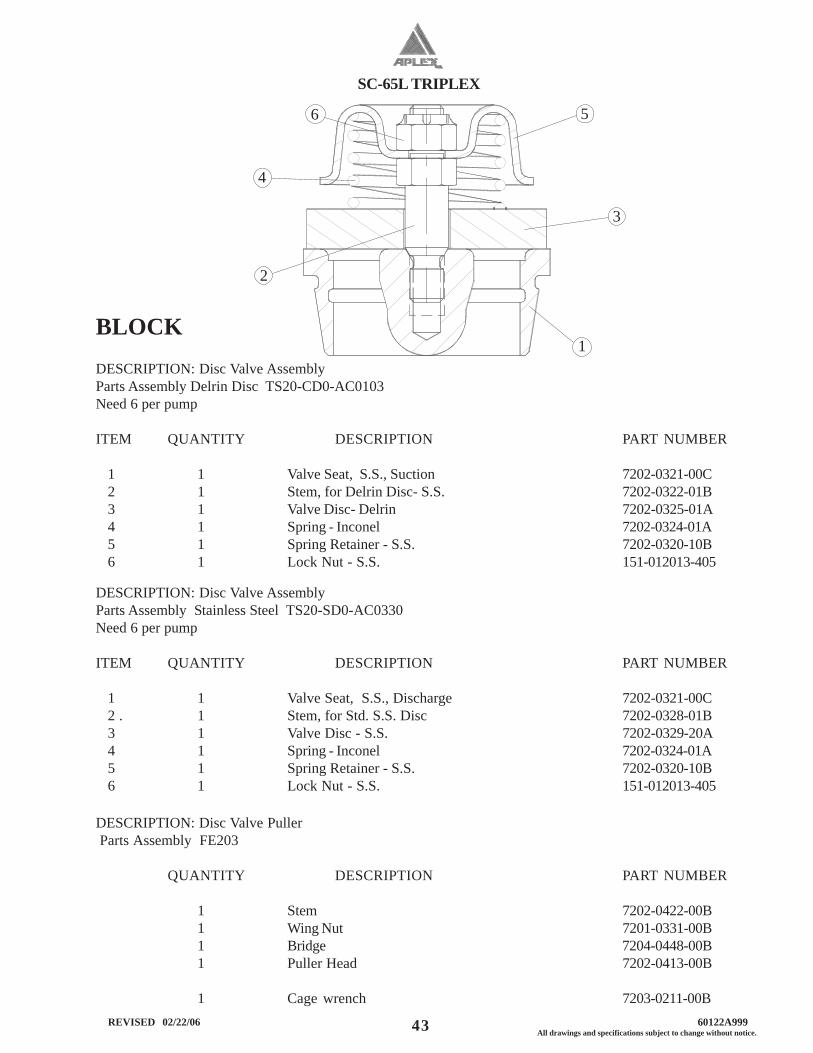
SC-65L TRIPLEX
43 All drawings and specifications subject to change without notice. REVISED 02/22/06 60122A999
BLOCKDESCRIPTION: Disc Valve AssemblyParts Assembly Delrin Disc TS20-CD0-AC0103Need 6 per pump
ITEM QUANTITY DESCRIPTION PART NUMBER
1 1 Valve Seat, S.S., Suction 7202-0321-00C2 1 Stem, for Delrin Disc- S.S. 7202-0322-01B3 1 Valve Disc- Delrin 7202-0325-01A4 1 Spring - Inconel 7202-0324-01A5 1 Spring Retainer - S.S. 7202-0320-10B6 1 Lock Nut - S.S. 151-012013-405
DESCRIPTION: Disc Valve AssemblyParts Assembly Stainless Steel TS20-SD0-AC0330Need 6 per pump
ITEM QUANTITY DESCRIPTION PART NUMBER
1 1 Valve Seat, S.S., Discharge 7202-0321-00C2 . 1 Stem, for Std. S.S. Disc 7202-0328-01B3 1 Valve Disc - S.S. 7202-0329-20A4 1 Spring - Inconel 7202-0324-01A5 1 Spring Retainer - S.S. 7202-0320-10B6 1 Lock Nut - S.S. 151-012013-405
DESCRIPTION: Disc Valve Puller Parts Assembly FE203
QUANTITY DESCRIPTION PART NUMBER
1 Stem 7202-0422-00B1 Wing Nut 7201-0331-00B1 Bridge 7204-0448-00B1 Puller Head 7202-0413-00B
1 Cage wrench 7203-0211-00B
2
4
6 5
3
1
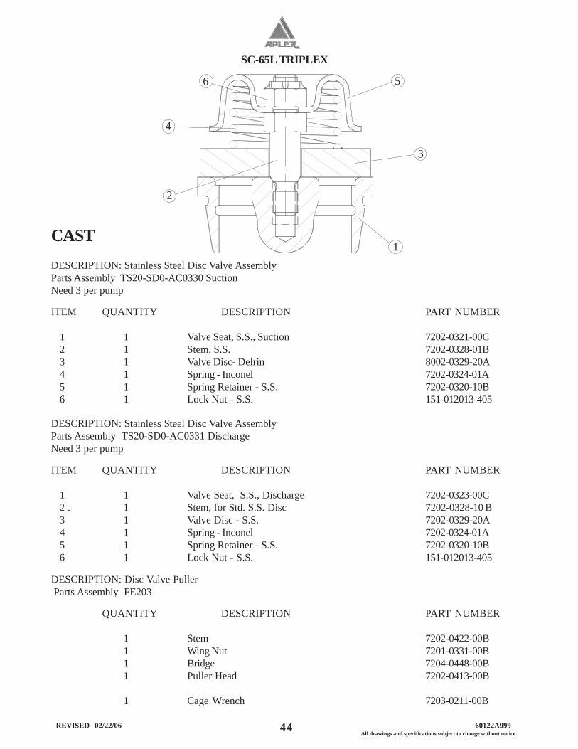
SC-65L TRIPLEX
44 REVISED 02/22/06 60122A999All drawings and specifications subject to change without notice.
CASTDESCRIPTION: Stainless Steel Disc Valve AssemblyParts Assembly TS20-SD0-AC0330 SuctionNeed 3 per pump
ITEM QUANTITY DESCRIPTION PART NUMBER
1 1 Valve Seat, S.S., Suction 7202-0321-00C2 1 Stem, S.S. 7202-0328-01B3 1 Valve Disc- Delrin 8002-0329-20A4 1 Spring - Inconel 7202-0324-01A5 1 Spring Retainer - S.S. 7202-0320-10B6 1 Lock Nut - S.S. 151-012013-405
DESCRIPTION: Stainless Steel Disc Valve AssemblyParts Assembly TS20-SD0-AC0331 DischargeNeed 3 per pump
ITEM QUANTITY DESCRIPTION PART NUMBER
1 1 Valve Seat, S.S., Discharge 7202-0323-00C2 . 1 Stem, for Std. S.S. Disc 7202-0328-10 B3 1 Valve Disc - S.S. 7202-0329-20A4 1 Spring - Inconel 7202-0324-01A5 1 Spring Retainer - S.S. 7202-0320-10B6 1 Lock Nut - S.S. 151-012013-405
DESCRIPTION: Disc Valve Puller Parts Assembly FE203
QUANTITY DESCRIPTION PART NUMBER
1 Stem 7202-0422-00B1 Wing Nut 7201-0331-00B1 Bridge 7204-0448-00B1 Puller Head 7202-0413-00B
1 Cage Wrench 7203-0211-00B
2
4
6 5
3
1
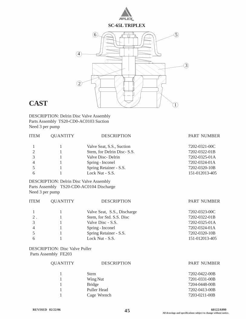
SC-65L TRIPLEX
45 All drawings and specifications subject to change without notice. REVISED 02/22/06 60122A999
CASTDESCRIPTION: Delrin Disc Valve AssemblyParts Assembly TS20-CD0-AC0103 SuctionNeed 3 per pump
ITEM QUANTITY DESCRIPTION PART NUMBER
1 1 Valve Seat, S.S., Suction 7202-0321-00C2 1 Stem, for Delrin Disc- S.S. 7202-0322-01B3 1 Valve Disc- Delrin 7202-0325-01A4 1 Spring - Inconel 7202-0324-01A5 1 Spring Retainer - S.S. 7202-0320-10B6 1 Lock Nut - S.S. 151-012013-405
DESCRIPTION: Delrin Disc Valve AssemblyParts Assembly TS20-CD0-AC0104 DischargeNeed 3 per pump
ITEM QUANTITY DESCRIPTION PART NUMBER
1 1 Valve Seat, S.S., Discharge 7202-0323-00C2 . 1 Stem, for Std. S.S. Disc 7202-0322-01B3 1 Valve Disc - S.S. 7202-0325-01A4 1 Spring - Inconel 7202-0324-01A5 1 Spring Retainer - S.S. 7202-0320-10B6 1 Lock Nut - S.S. 151-012013-405
DESCRIPTION: Disc Valve Puller Parts Assembly FE203
QUANTITY DESCRIPTION PART NUMBER
1 Stem 7202-0422-00B1 Wing Nut 7201-0331-00B1 Bridge 7204-0448-00B1 Puller Head 7202-0413-00B1 Cage Wrench 7203-0211-00B
2
4
6 5
3
1
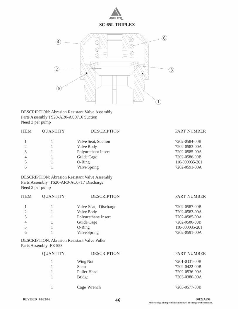
SC-65L TRIPLEX
46 REVISED 02/22/06 60122A999All drawings and specifications subject to change without notice.
DESCRIPTION: Abrasion Resistant Valve AssemblyParts Assembly TS20-AR0-AC0716 SuctionNeed 3 per pump
ITEM QUANTITY DESCRIPTION PART NUMBER
1 1 Valve Seat, Suction 7202-0584-00B2 1 Valve Body 7202-0583-00A3 1 Polyurethant Insert 7202-0585-00A4 1 Guide Cage 7202-0586-00B5 1 O-Ring 110-000035-2016 1 Valve Spring 7202-0591-00A
DESCRIPTION: Abrasion Resistant Valve AssemblyParts Assembly TS20-AR0-AC0717 DischargeNeed 3 per pump
ITEM QUANTITY DESCRIPTION PART NUMBER
1 1 Valve Seat, Discharge 7202-0587-00B2 1 Valve Body 7202-0583-00A3 1 Polyurethane Insert 7202-0585-00A4 1 Guide Cage 7202-0586-00B5 1 O-Ring 110-000035-2016 1 Valve Spring 7202-0591-00A
DESCRIPTION: Abrasion Resistant Valve PullerParts Assembly FE 553
QUANTITY DESCRIPTION PART NUMBER
1 Wing Nut 7201-0331-00B1 Stem 7202-0422-00B1 Puller Head 7202-0536-00A1 Bridge 7203-0380-00A
1 Cage Wrench 7203-0577-00B
2
46
3
1
5
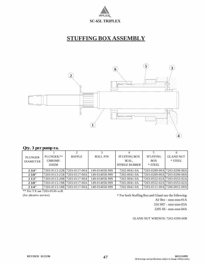
SC-65L TRIPLEX
47 All drawings and specifications subject to change without notice. REVISED 02/22/06 60122A999
STUFFING BOX ASSEMBLY
65
2
1
4
3
Qty. 3 per pump ea.
PLUNGER DIAMET ER
1 PLUNGER,**
CHROME-OXIDE
2 BAFFLE
3 ROLL PIN
4 STUFFING BOX
SEAL, NITRILE RUBBER
5 STUFFING
BOX * STEEL
6 GLAND NUT
* STEEL
2 3/4" 7203-0113-22B 7203-0117-00A 149-014058-999 7202-0041-0A 7203-0289-00A 7203-0290-00A2 5/8" 7203-0113-21B 7203-0117-00A 149-014058-999 7202-0041-0A 7203-0289-00A 7203-0290-00A2 1/2" 7203-0113-20B 7203-0117-00A 149-014058-999 7202-0041-0A 7203-0552-02A 7203-0553-02A2 3/8" 7203-0113-19B 7203-0117-00A 149-014058-999 7202-0041-0A 7203-0552-02A 7203-0553-02A2 1/4" 7203-0113-18B 7203-0117-00A 149-014058-999 7202-0041-0A 7203-0111-00A 7206-0012-00A
** For T X use 7203-0530-xxB (for abrasive service) * For both Stuffing Box and Gland use the following:
Al/ Brz - xxxx-xxxx-01A316 SST - xxxx-xxxx-03A2205 SS - xxxx-xxxx-04A
GLAND NUT WRENCH: 7202-0399-00B
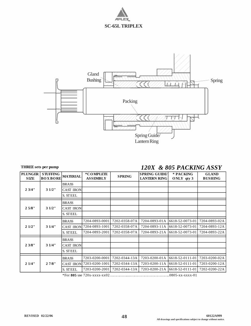
SC-65L TRIPLEX
48 REVISED 02/22/06 60122A999All drawings and specifications subject to change without notice.
GlandBushing
Spring Guide/Lantern Ring
Packing
Spring
PLUNGER SIZE
STUFFING BO X BO RE MATERIAL *CO MPLETE
ASSEMBLY SPRING SPRING GUIDE/ LANTERN RING
* PACKING O NLY qty 3
GLAND BUSHING
BRASSCAST IRONS. STEEL
BRASSCAST IRONS. STEEL
BRASS 7204-0893-0001 7202-0358-07A 7204-0893-01A 6618-52-0073-01 7204-0893-02ACAST IRON 7204-0893-1001 7202-0358-07A 7204-0893-11A 6618-52-0073-01 7204-0893-12A
S. STEEL 7204-0893-2001 7202-0358-07A 7204-0893-21A 6618-52-0073-01 7204-0893-22A
BRASSCAST IRONS. STEEL
BRASS 7203-0200-0001 7202-0344-13A 7203-0200-01A 6618-52-0111-01 7203-0200-02A
CAST IRON 7203-0200-1001 7202-0344-13A 7203-0200-11A 6618-52-0111-01 7203-0200-12AS. STEEL 7203-0200-2001 7202-0344-13A 7203-0200-21A 6618-52-0111-01 7202-0200-22A*For 805 use 720x-xxxx-xx02…………….....……………………………..0805-xx-xxxx-01
2 3/4" 3 1/2"
2 1/2"
120X & 805 PACKING ASSY
2 1/4" 2 7/8"
2 3/8" 3 1/4"
3 1/4"
2 5/8" 3 1/2"
THREE sets per pump
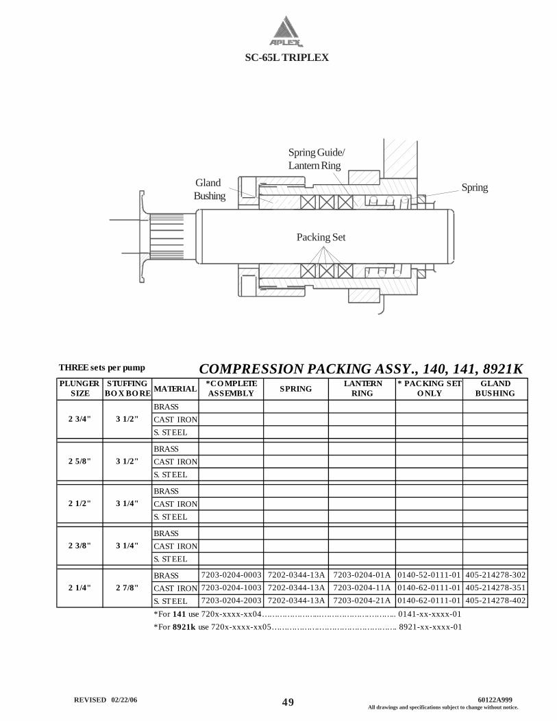
SC-65L TRIPLEX
49 All drawings and specifications subject to change without notice. REVISED 02/22/06 60122A999
GlandBushing
Spring
Packing Set
Spring Guide/Lantern Ring
PLUNGER SIZE
STUFFING BO X BO RE MATERIAL *CO MPLETE
ASSEMBLY SPRING LANTERN RING
* PACKING SET O NLY
GLAND BUSHING
BRASSCAST IRONS. STEEL
BRASSCAST IRONS. STEEL
BRASSCAST IRONS. STEEL
BRASSCAST IRONS. STEEL
BRASS 7203-0204-0003 7202-0344-13A 7203-0204-01A 0140-52-0111-01 405-214278-302CAST IRON 7203-0204-1003 7202-0344-13A 7203-0204-11A 0140-62-0111-01 405-214278-351S. STEEL 7203-0204-2003 7202-0344-13A 7203-0204-21A 0140-62-0111-01 405-214278-402*For 141 use 720x-xxxx-xx04…………………...……………….……….. 0141-xx-xxxx-01*For 8921k use 720x-xxxx-xx05……………….…………………………. 8921-xx-xxxx-01
2 5/8" 3 1/2"
2 1/4"
2 3/8" 3 1/4"
2 1/2"
THREE sets per pump COMPRESSION PACKING ASSY., 140, 141, 8921K
3 1/4"
2 7/8"
2 3/4" 3 1/2"
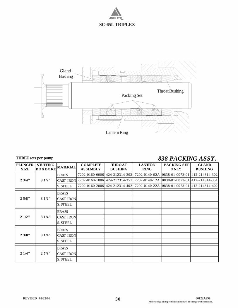
SC-65L TRIPLEX
50 REVISED 02/22/06 60122A999All drawings and specifications subject to change without notice.
Gland Bushing
Throat Bushing
Lantern Ring
Packing Set
PLUNGER SIZE
STUFFING BO X BO RE MATERIAL CO MPLETE
ASSEMBLYTHRO AT
BUSHINGLANTERN
RING PACKING SET
O NLY GLAND
BUSHINGBRASS 7202-0160-0006 424-212314-302 7202-0140-02A 0838-01-0073-01 412-214314-302CAST IRON 7202-0160-1006 424-212314-351 7202-0140-12A 0838-01-0073-01 412-214314-351S. STEEL 7202-0160-2006 424-212314-402 7202-0140-22A 0838-01-0073-01 412-214314-402
BRASSCAST IRONS. STEEL
BRASSCAST IRONS. STEEL
BRASSCAST IRONS. STEEL
BRASSCAST IRONS. STEEL
2 1/4" 2 7/8"
2 3/4" 3 1/2"
2 1/2" 3 1/4"
2 5/8" 3 1/2"
3 1/4"2 3/8"
THREE sets per pump 838 PACKING ASSY.
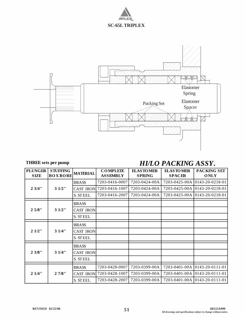
SC-65L TRIPLEX
51 All drawings and specifications subject to change without notice. REVISED 02/22/06 60122A999
Packing Set
Elastomer Spring
Elastomer Spacer
PLUNGER SIZE
STUFFING BO X BO RE MATERIAL COMPLETE
ASSEMBLY ELASTOMER
SPRINGELASTO MER
SPACERPACKING SET
ONLY BRASS 7203-0416-0007 7203-0424-00A 7203-0425-00A 0143-20-0218-01CAST IRON 7203-0416-1007 7203-0424-00A 7203-0425-00A 0143-20-0218-01
S. ST EEL 7203-0416-2007 7203-0424-00A 7203-0425-00A 0143-20-0218-01
BRASSCAST IRONS. ST EEL
BRASSCAST IRONS. ST EEL
BRASSCAST IRONS. ST EEL
BRASS 7203-0428-0007 7203-0399-00A 7203-0401-00A 0143-20-0111-01CAST IRON 7203-0428-1007 7203-0399-00A 7203-0401-00A 0143-20-0111-01
S. ST EEL 7203-0428-2007 7203-0399-00A 7203-0401-00A 0143-20-0111-01
3 1/2"
THREE sets per pump HI/LO PACKING ASSY.
2 1/4" 2 7/8"
3 1/4"2 3/8"
2 3/4" 3 1/2"
2 1/2" 3 1/4"
2 5/8"
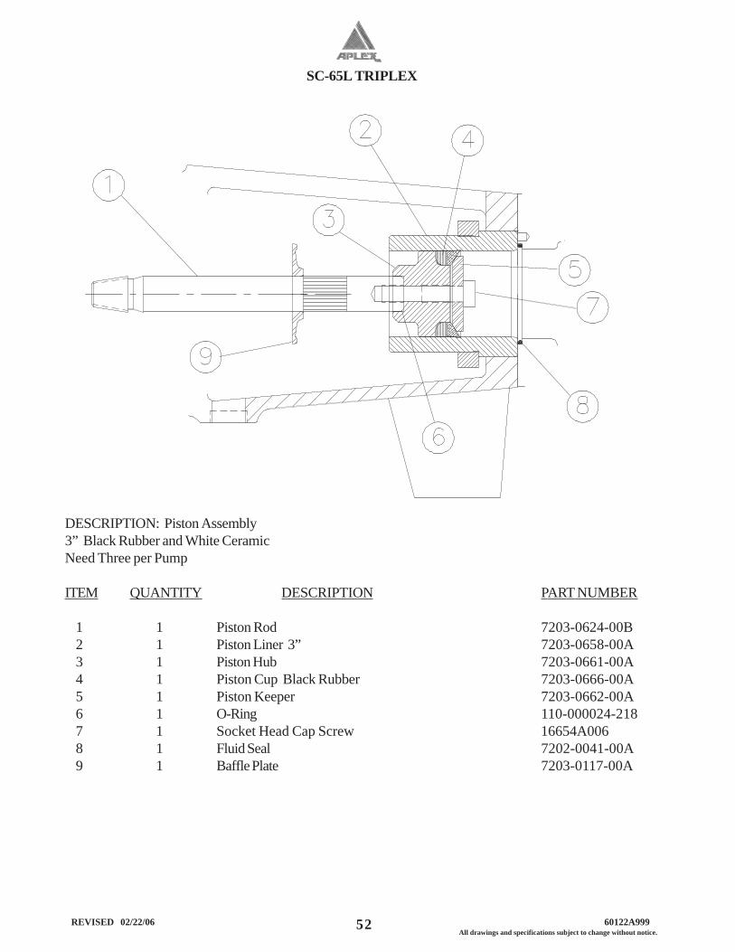
SC-65L TRIPLEX
52 REVISED 02/22/06 60122A999All drawings and specifications subject to change without notice.
DESCRIPTION: Piston Assembly3” Black Rubber and White CeramicNeed Three per Pump
ITEM QUANTITY DESCRIPTION PART NUMBER
1 1 Piston Rod 7203-0624-00B2 1 Piston Liner 3” 7203-0658-00A3 1 Piston Hub 7203-0661-00A4 1 Piston Cup Black Rubber 7203-0666-00A5 1 Piston Keeper 7203-0662-00A6 1 O-Ring 110-000024-2187 1 Socket Head Cap Screw 16654A0068 1 Fluid Seal 7202-0041-00A9 1 Baffle Plate 7203-0117-00A
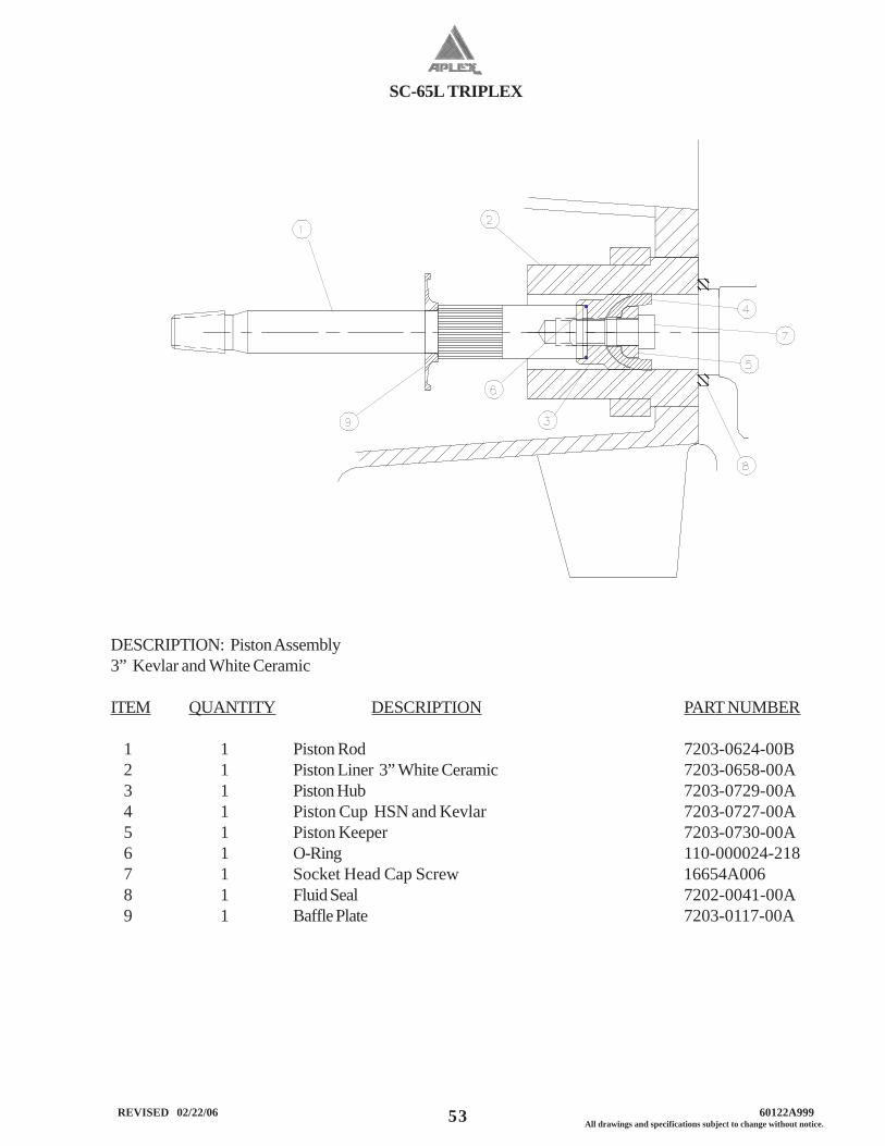
SC-65L TRIPLEX
53 All drawings and specifications subject to change without notice. REVISED 02/22/06 60122A999
DESCRIPTION: Piston Assembly3” Kevlar and White Ceramic
ITEM QUANTITY DESCRIPTION PART NUMBER
1 1 Piston Rod 7203-0624-00B2 1 Piston Liner 3” White Ceramic 7203-0658-00A3 1 Piston Hub 7203-0729-00A4 1 Piston Cup HSN and Kevlar 7203-0727-00A5 1 Piston Keeper 7203-0730-00A6 1 O-Ring 110-000024-2187 1 Socket Head Cap Screw 16654A0068 1 Fluid Seal 7202-0041-00A9 1 Baffle Plate 7203-0117-00A