Bolted Repair Design and Process Considerations · Bolted Repair Design and Process Considerations...
19
Bolted Repair Design and Process Considerations Jeff Berner 787 Wing/Empennage/ Landing Gear Presented to CACRC, May 9-11, 2007
-
Upload
truongkhanh -
Category
Documents
-
view
249 -
download
4
Transcript of Bolted Repair Design and Process Considerations · Bolted Repair Design and Process Considerations...
Bolted Repair Design and Process Considerations
Jeff Berner
787 Wing/Empennage/Landing Gear
Presented to CACRC, May 9-11, 2007
COPYRIGHT © 2007 THE BOEING COMPANY
Agenda
Introduction
Design for Repairability
Bolted Repair Design Considerations
Bolted Repair Analytical Considerations
Material/Fastener Selection
Bolted Repair Process Sensitivity
Conclusions
COPYRIGHT © 2007 THE BOEING COMPANY
Introduction
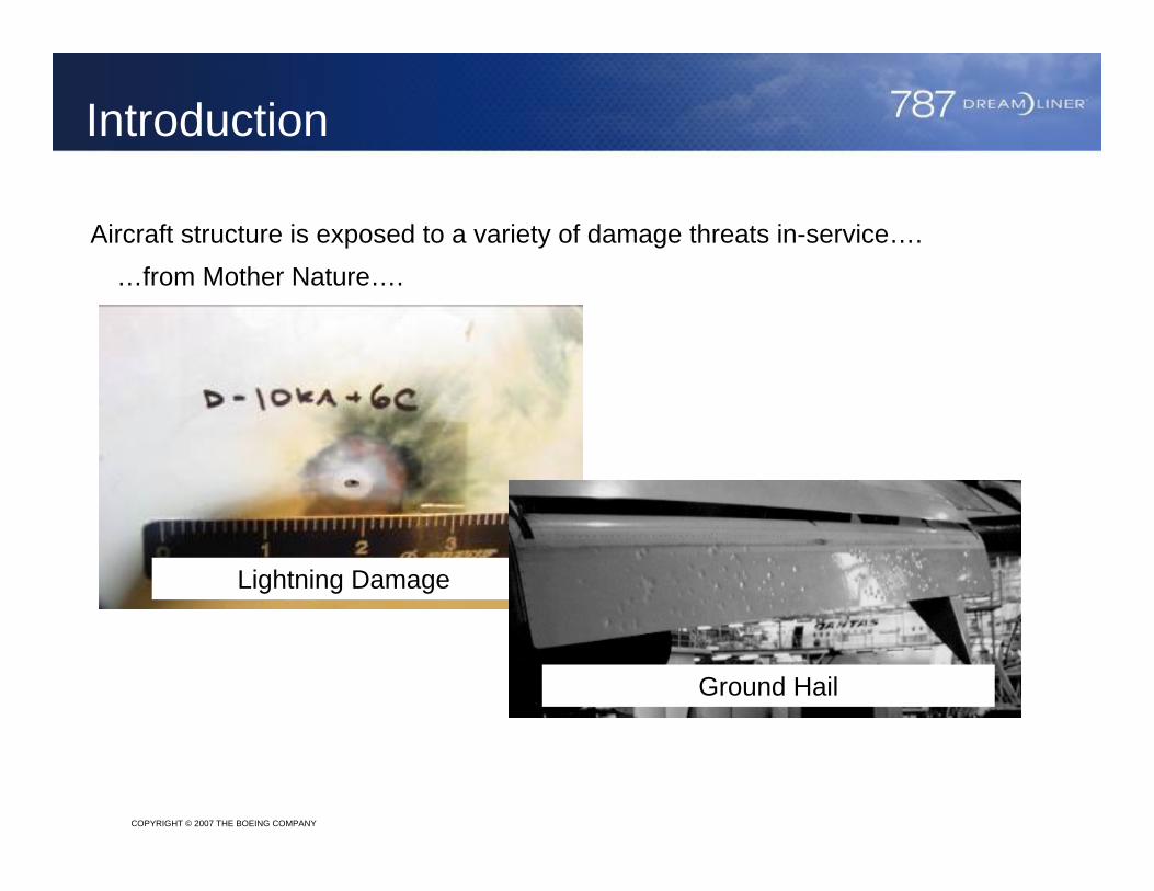
Aircraft structure is exposed to a variety of damage threats in-service….
Lightning Damage
Ground Hail
…from Mother Nature….
COPYRIGHT © 2007 THE BOEING COMPANY
Introduction
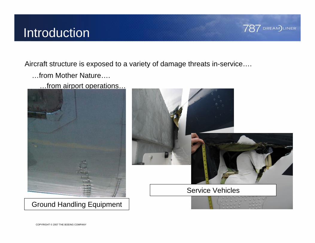
Aircraft structure is exposed to a variety of damage threats in-service….
Service Vehicles
…from Mother Nature….…from airport operations…
Ground Handling Equipment
COPYRIGHT © 2007 THE BOEING COMPANY
Introduction
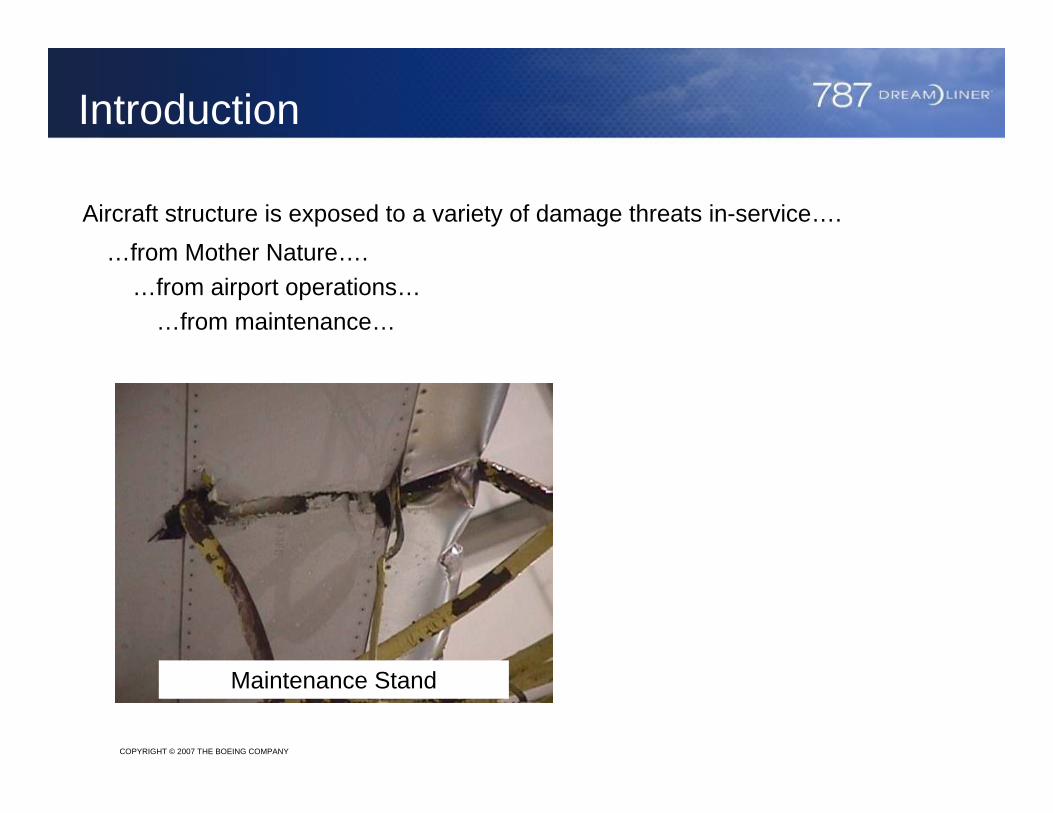
Aircraft structure is exposed to a variety of damage threats in-service….…from Mother Nature….
Maintenance Stand
…from airport operations……from maintenance…
COPYRIGHT © 2007 THE BOEING COMPANY
Introduction
…from Mother Nature….…from airport operations…
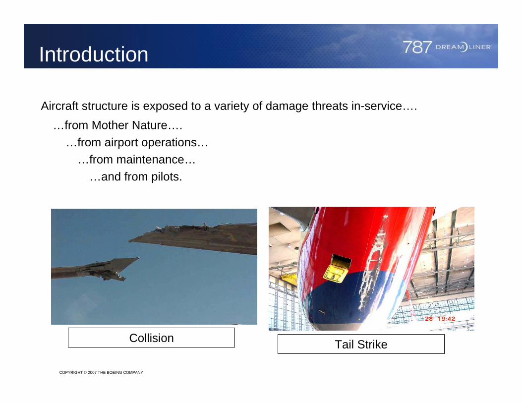
…from maintenance……and from pilots.
Aircraft structure is exposed to a variety of damage threats in-service….
Collision Tail Strike
COPYRIGHT © 2007 THE BOEING COMPANY
Introduction
…from Mother Nature….…from airport operations…
…from maintenance……and from pilots.
Aircraft structure is exposed to a variety of damage threats in-service….
Meeting airline expectations for repairability begins with an understanding of the threat environment and the repairs that may be expected in-service.
Airlines require a variety of repair options which permit them to choose the best repair for the situation.
When a large damage occurs, bonded repairs may become impractical or technically not feasible and a bolted repair design will be required.
Fail-safety principles may direct use of bolted repairs when a bonded repair size may exceed the residual strength of the component should the bondline fail.
COPYRIGHT © 2007 THE BOEING COMPANY
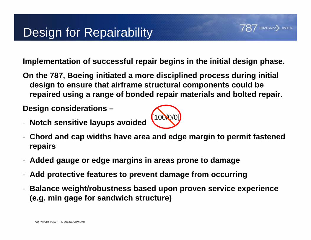
Implementation of successful repair begins in the initial design phase.
On the 787, Boeing initiated a more disciplined process during initial design to ensure that airframe structural components could be repaired using a range of bonded repair materials and bolted repair.
Design considerations –
- Notch sensitive layups avoided
- Chord and cap widths have area and edge margin to permit fastened repairs
- Added gauge or edge margins in areas prone to damage
- Add protective features to prevent damage from occurring
- Balance weight/robustness based upon proven service experience (e.g. min gage for sandwich structure)
Design for Repairability
[100/0/0]
COPYRIGHT © 2007 THE BOEING COMPANY
Design for Repairability
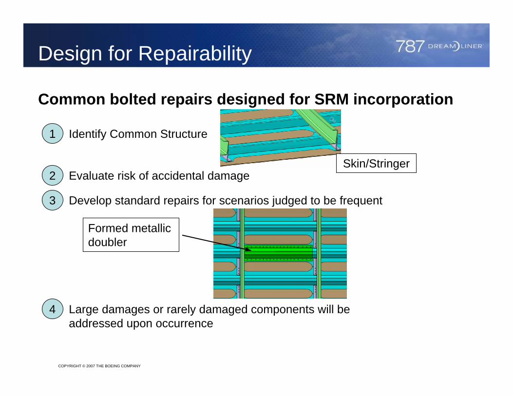
Common bolted repairs designed for SRM incorporation
1 Identify Common Structure
2 Evaluate risk of accidental damageSkin/Stringer
3 Develop standard repairs for scenarios judged to be frequent
4 Large damages or rarely damaged components will be addressed upon occurrence
Formed metallicdoubler
COPYRIGHT © 2007 THE BOEING COMPANY
Design for Repairability
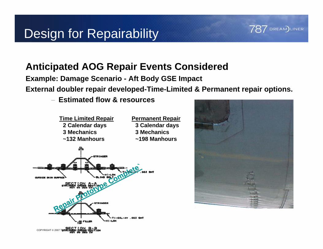
Anticipated AOG Repair Events ConsideredExample: Damage Scenario - Aft Body GSE ImpactExternal doubler repair developed-Time-Limited & Permanent repair options.
− Estimated flow & resources
Time Limited Repair2 Calendar days3 Mechanics~132 Manhours
Permanent Repair3 Calendar days3 Mechanics~198 Manhours
Repair Prototype Complete
Repair Prototype Complete`̀
COPYRIGHT © 2007 THE BOEING COMPANY
Bolted Repair Design Considerations
When developing the design for a bolted repair, the repair engineer needs to account for –
Replacing load paths
Matching EA, EI- hardpoint effects (load increase factor)- repair effectiveness to reduce stress concentration due to damage
Determining the repair materials which may be available, e.g. titanium sheet, aluminum sheet
What fasteners might be available (type, diameter, grip length)
Producibility considerations, e.g. bend radius for formed sheet stock, accessibility for drill motors, one-sided access, etc.
Capability of mechanics conducting the repairs
COPYRIGHT © 2007 THE BOEING COMPANY
Bolted Repair Analysis Considerations
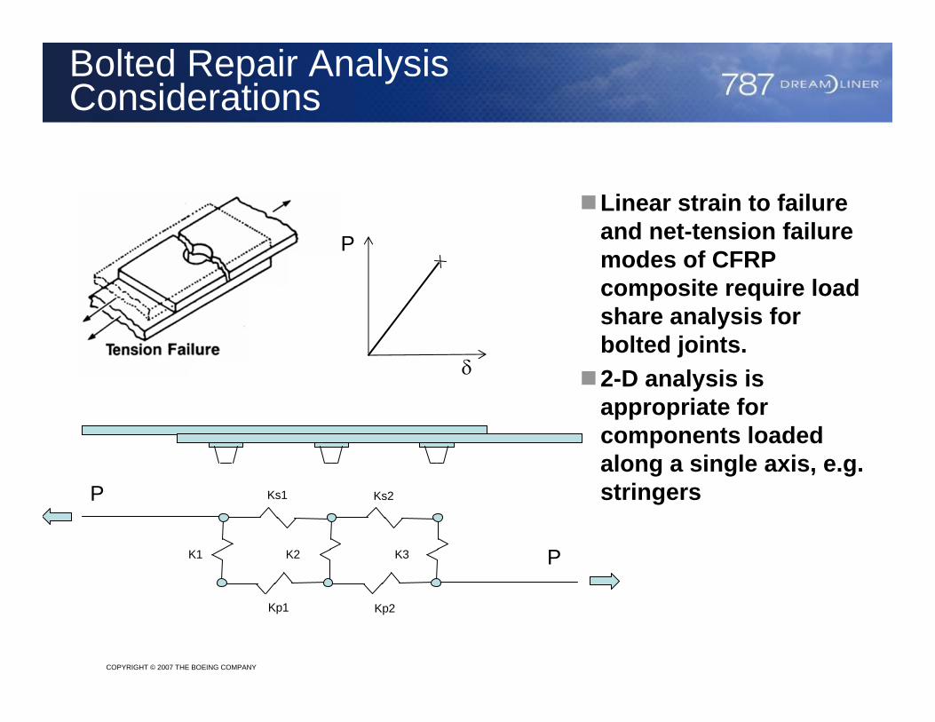
Linear strain to failure and net-tension failure modes of CFRP composite require load share analysis for bolted joints.2-D analysis is appropriate for components loaded along a single axis, e.g. stringers
P
δ
P
PK1 K2 K3
Ks1 Ks2
Kp1 Kp2
COPYRIGHT © 2007 THE BOEING COMPANY
Bolted Repair Analysis Considerations
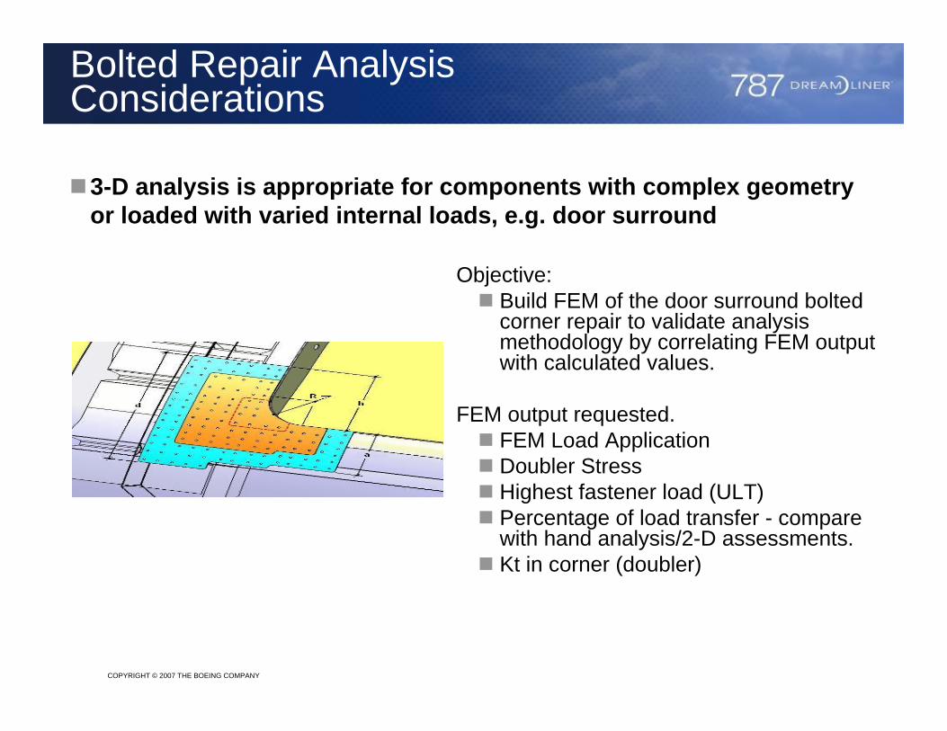
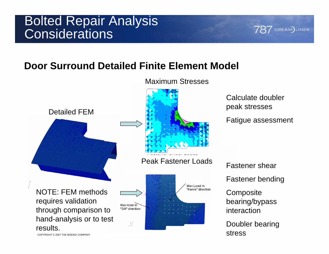
3-D analysis is appropriate for components with complex geometry or loaded with varied internal loads, e.g. door surround
Objective:Build FEM of the door surround bolted corner repair to validate analysis methodology by correlating FEM output with calculated values.
FEM output requested.FEM Load ApplicationDoubler Stress Highest fastener load (ULT)Percentage of load transfer - compare with hand analysis/2-D assessments.Kt in corner (doubler)
COPYRIGHT © 2007 THE BOEING COMPANY
Bolted Repair Analysis Considerations
Door Surround Detailed Finite Element Model
Detailed FEM
Maximum Stresses
Peak Fastener Loads
NOTE: FEM methods requires validation through comparison to hand-analysis or to test results.
Calculate doubler peak stresses
Fatigue assessment
Fastener shear
Fastener bending
Composite bearing/bypass interaction
Doubler bearing stress
COPYRIGHT © 2007 THE BOEING COMPANY
Bolted Repair Analysis Considerations
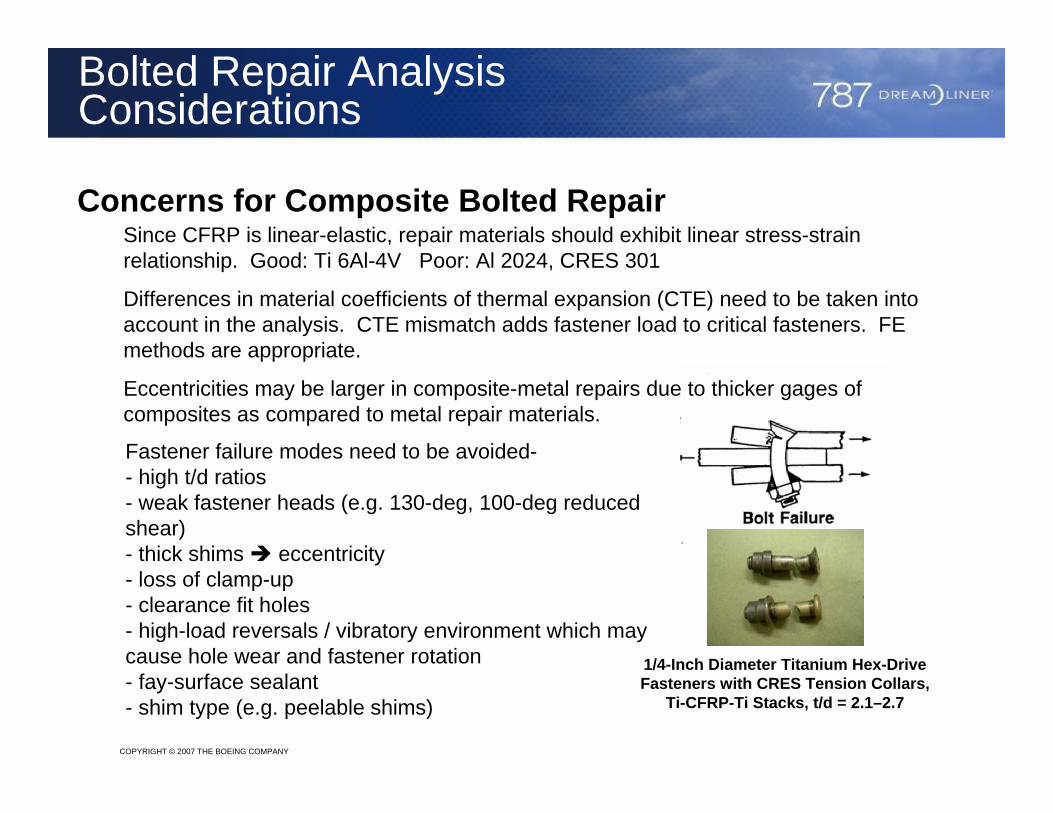
Concerns for Composite Bolted RepairSince CFRP is linear-elastic, repair materials should exhibit linear stress-strain relationship. Good: Ti 6Al-4V Poor: Al 2024, CRES 301
Differences in material coefficients of thermal expansion (CTE) need to be taken into account in the analysis. CTE mismatch adds fastener load to critical fasteners. FE methods are appropriate.
Eccentricities may be larger in composite-metal repairs due to thicker gages of composites as compared to metal repair materials.
Fastener failure modes need to be avoided-- high t/d ratios- weak fastener heads (e.g. 130-deg, 100-deg reduced shear)- thick shims eccentricity - loss of clamp-up- clearance fit holes- high-load reversals / vibratory environment which may cause hole wear and fastener rotation- fay-surface sealant- shim type (e.g. peelable shims)
1/4-Inch Diameter Titanium Hex-Drive Fasteners with CRES Tension Collars,
Ti-CFRP-Ti Stacks, t/d = 2.1–2.7
COPYRIGHT © 2007 THE BOEING COMPANY
Material/Fastener Selection
Materials, Finishes and Fasteners need to be consistent with structural requirements, EME requirements, and corrosion protection requirements
Repairs need to be tested to validate that EME requirements are met. Fuel tanks and airplane systems may dictate different EME requirements than for metal airframe structure.
Repair materials need to be either compatible for galvanic corrosion or finishes/sealants must prevent galvanic corrosion. Sealants may reduce fatigue life and adversely affect static joint strength.
One-sided fasteners where used require back-side inspection. One-sided fasteners may require more frequent inspection due to concerns with loss of clamp-up.

COPYRIGHT © 2007 THE BOEING COMPANY
Bolted Repair Process Sensitivity
There is a perception that a bonded repair is highly susceptible to process variability and thus a bolted repairs are preferable. Bolted repairs exhibit process sensitivity as well which needs to be accounted for:
- meeting close tolerance hole requirements
- using backup to avoid fiber breakout
- using dull bits or incorrect speeds/feeds which can cause heat damage to metal or “burn” composite
- shimming & fit-up stresses
- application of sealant
- drilling through metal/composite stackup. Metal chips can cause damage to composite holes
- drill wandering or hole misalignment if drill guides are not used
- deburring holes
When they occur, such failures in process are likely to occur throughout the repair and not at individual locations within the repair.
COPYRIGHT © 2007 THE BOEING COMPANY
Conclusions
Ability to accomplish bolted repairs needs to be considered during initial design when choosing layup and structural configuration
Bolted repairs may be planned for based upon service experience which indicates susceptibility to damage and the types of damage events
Structural analysis for bolted repair will likely require as extensive analysis (if not more) than what is required for initial design. This is required because failure-modes are different for composite-metal bolted repairs than for repairs to metal aircraft
As with any repair, materials, fasteners and finishes need to be selected to be compatible with the application and requirements.
As with any repair, attention to detail and adherence to processes are required