BOLLFILTER Simplex TYPE 1.12 Filter... · 2016-07-06 · TYPE 1.12.2 BOLLFILTER Simplex with...
2
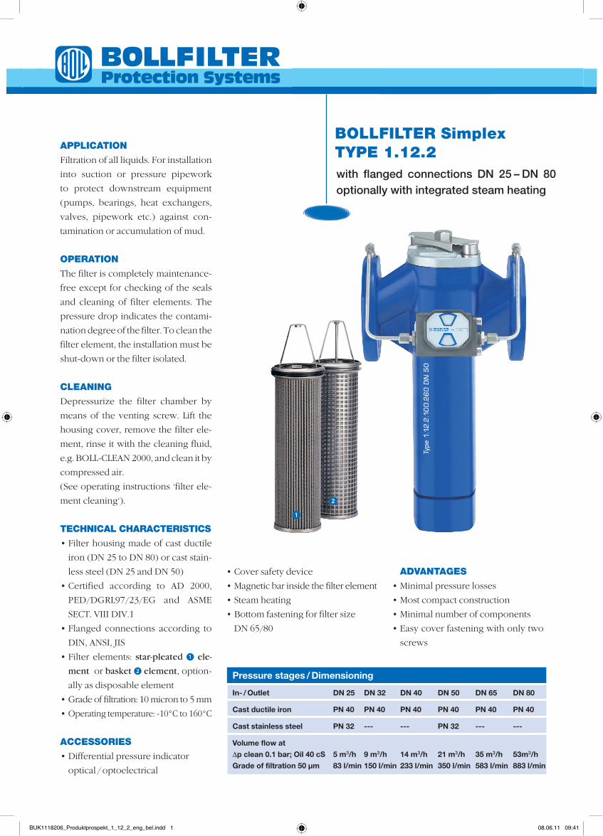
TYPE 1.12.2 BOLLFILTER Simplex with flanged connections DN 25 – DN 80 optionally with integrated steam heating APPLICATION Filtration of all liquids. For installation into suction or pressure pipework to protect downstream equipment (pumps, bearings, heat exchangers, valves, pipework etc.) against con- tamination or accumulation of mud. OPERATION The filter is completely maintenance- free except for checking of the seals and cleaning of filter elements. The pressure drop indicates the contami- nation degree of the filter. To clean the filter element, the installation must be shut-down or the filter isolated. CLEANING Depressurize the filter chamber by means of the venting screw. Lift the housing cover, remove the filter ele- ment, rinse it with the cleaning fluid, e.g. BOLL-CLEAN 2000, and clean it by compressed air. (See operating instructions ‘filter ele- ment cleaning‘). TECHNICAL CHARACTERISTICS • Filter housing made of cast ductile iron (DN 25 to DN 80) or cast stain- less steel (DN 25 and DN 50) • Certified according to AD 2000, PED/DGRL97/23/EG and ASME SECT. VIII DIV.1 • Flanged connections according to DIN, ANSI, JIS • Filter elements: star-pleated 1 ele- ment or basket 2 element, option- ally as disposable element • Grade of filtration: 10 micron to 5 mm • Operating temperature: -10°C to 160°C ACCESSORIES • Differential pressure indicator optical / optoelectrical • Cover safety device • Magnetic bar inside the filter element • Steam heating • Bottom fastening for filter size DN 65/80 ADVANTAGES • Minimal pressure losses • Most compact construction • Minimal number of components • Easy cover fastening with only two screws 2 1 Pressure stages / Dimensioning In- / Outlet DN 25 DN 32 DN 40 DN 50 DN 65 DN 80 Cast ductile iron PN 40 PN 40 PN 40 PN 40 PN 40 PN 40 Cast stainless steel PN 32 --- --- PN 32 --- --- Volume flow at Δp clean 0.1 bar; Oil 40 cS 5 m 3 /h 9 m 3 /h 14 m 3 /h 21 m 3 /h 35 m 3 /h 53m 3 /h Grade of filtration 50 µm 83 l/min 150 l/min 233 l/min 350 l/min 583 l/min 883 l/min BUK1118206_Produktprospekt_1_12_2_eng_bel.indd 1 08.06.11 09:41
Transcript of BOLLFILTER Simplex TYPE 1.12 Filter... · 2016-07-06 · TYPE 1.12.2 BOLLFILTER Simplex with...
TYPE 1.12.2BOLLFILTER Simplex
with flanged connections DN 25 – DN 80 optionally with integrated steam heating
APPLIcATIOn
Filtration of all liquids. For installation
into suction or pressure pipework
to protect downstream equipment
(pum ps, bearings, heat exchangers,
valves, pipework etc.) against con-
tamination or accumulation of mud.
OPERATIOn
The filter is completely maintenance-
free except for checking of the seals
and cleaning of filter elements. The
pressure drop indicates the contami-
nation degree of the filter. To clean the
filter element, the installation must be
shut-down or the filter isolated.
cLEAnIng
Depressurize the filter chamber by
means of the venting screw. Lift the
housing cover, remove the filter ele-
ment, rinse it with the cleaning fluid,
e.g. BOLL-CLEAN 2000, and clean it by
compressed air.
(See operating instructions ‘filter ele-
ment cleaning‘).
TEchnIcAL chARAcTERISTIcS
• Filter housing made of cast ductile
iron (DN 25 to DN 80) or cast stain-
less steel (DN 25 and DN 50)
• Certified according to AD 2000,
PED/DGRL97/23/EG and ASME
SECT. VIII DIV.1
• Flanged connections according to
DIN, ANSI, JIS
• Filter elements: star-pleated 1 ele-
ment or basket 2 element, option-
ally as disposable element
• Grade of filtration: 10 micron to 5 mm
• Operating temperature: -10°C to 160°C
AccESSORIES
• Differential pressure indicator
optical / optoelectrical
• Cover safety device
• Magnetic bar inside the filter element
• Steam heating
• Bottom fastening for filter size
DN 65/80
AdvAnTAgES
• Minimal pressure losses
• Most compact construction
• Minimal number of components
• Easy cover fastening with only two
screws
2
1
Pressure stages / Dimensioning
In- / Outlet DN 25 DN 32 DN 40 DN 50 DN 65 DN 80
Cast ductile iron PN 40 PN 40 PN 40 PN 40 PN 40 PN 40
Cast stainless steel PN 32 --- --- PN 32 --- ---
Volume flow at
Δp clean 0.1 bar; Oil 40 cS 5 m3/h 9 m3/h 14 m3/h 21 m3/h 35 m3/h 53m3/h
Grade of filtration 50 µm 83 l/min 150 l/min 233 l/min 350 l/min 583 l/min 883 l/min
BUK1118206_Produktprospekt_1_12_2_eng_bel.indd 1 08.06.11 09:41
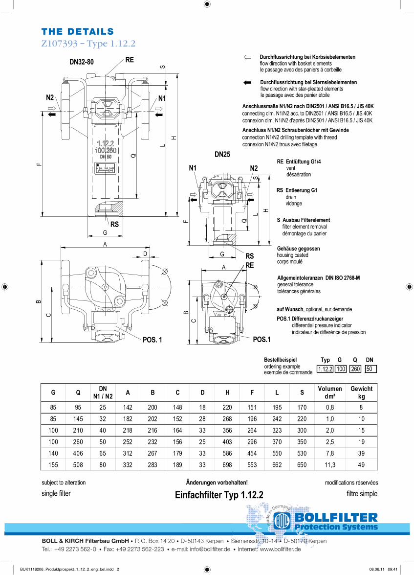
ThE dETAILSZ107393 – Type 1.12.2
BOLL & KIRCH Filterbau GmbH • P. O. Box 14 20 • D-50143 Kerpen • Siemensstr. 10-14 • D-50170 KerpenTel.: +49 2273 562-0 • Fax: +49 2273 562-223 • e-mail: [email protected] • Internet: www.bollfilter.de
subject to alteration Änderungen vorbehalten!
single filter Einfachfilter Typ 1.12.2
Z107393Typ 1.12.227.07.2009
modifications réservées
filtre simple
Bestellbeispiel
Durchflussrichtung bei Korbsiebelementen
ordering example
flow direction with basket elements
exemple de commande
le passage avec des paniers á corbeille
1.12.2 100 260 50QTyp DN
RE Entlüftung G1/4
RS Entleerung G1
S Ausbau Filterelement
POS.1 Differenzdruckanzeigerauf Wunsch
Allgemeintoleranzen DIN ISO 2768-M
Anschlussmaße N1/N2 nach DIN2501 / ANSI B16.5 / JIS 40K
Gehäuse gegossen
vent
drain
filter element removal
differential pressure indicator
, optional
general tolerance
connecting dim. N1/N2 acc. to DIN2501 / ANSI B16.5 / JIS 40K
housing casted
désaération
vidange
démontage du panier
indicateur de differénce de pression
, sur demande
tolérances générales
connexion dim. N1/N2 d'aprés DIN2501 / ANSI B16.5 / JIS 40K
corps moulé
G
F
Q
RSG
N2 N1
A
CB
S
RE
L
G Q DN N1 / N2 A B C D H F L S Volumen
dm³ Gewicht
kg 85 95 25 142 200 148 18 220 151 195 170 0,8 8 85 145 32 182 202 152 28 268 196 242 220 1,0 10
100 210 40 218 216 164 33 356 264 323 300 2,0 15 100 260 50 252 232 156 25 403 296 370 350 2,5 19 140 406 65 312 267 179 33 586 454 550 530 7,8 39 155 508 80 332 283 189 33 698 553 662 650 11,3 49
Durchflussrichtung bei Sternsiebelementenflow direction with star-pleated elementsle passage avec des panier étoile
H
POS. 1
D
Anschluss N1/N2 Schraubenlöcher mit Gewindeconnection N1/N2 drilling template with threadconnexion N1/N2 trous avec filetage
RS
POS.1
N1 N2
RE
DN25
DN32-80
Q
LS
C
HA
B
G
F
subject to alteration Änderungen vorbehalten!
single filter Einfachfilter Typ 1.12.2
Z107393Typ 1.12.227.07.2009
modifications réservées
filtre simple
Bestellbeispiel
Durchflussrichtung bei Korbsiebelementen
ordering example
flow direction with basket elements
exemple de commande
le passage avec des paniers á corbeille
1.12.2 100 260 50QTyp DN
RE Entlüftung G1/4
RS Entleerung G1
S Ausbau Filterelement
POS.1 Differenzdruckanzeigerauf Wunsch
Allgemeintoleranzen DIN ISO 2768-M
Anschlussmaße N1/N2 nach DIN2501 / ANSI B16.5 / JIS 40K
Gehäuse gegossen
vent
drain
filter element removal
differential pressure indicator
, optional
general tolerance
connecting dim. N1/N2 acc. to DIN2501 / ANSI B16.5 / JIS 40K
housing casted
désaération
vidange
démontage du panier
indicateur de differénce de pression
, sur demande
tolérances générales
connexion dim. N1/N2 d'aprés DIN2501 / ANSI B16.5 / JIS 40K
corps moulé
G
F
Q
RSG
N2 N1
A
CB
S
RE
L
G Q DN N1 / N2 A B C D H F L S Volumen
dm³ Gewicht
kg 85 95 25 142 200 148 18 220 151 195 170 0,8 8 85 145 32 182 202 152 28 268 196 242 220 1,0 10
100 210 40 218 216 164 33 356 264 323 300 2,0 15 100 260 50 252 232 156 25 403 296 370 350 2,5 19 140 406 65 312 267 179 33 586 454 550 530 7,8 39 155 508 80 332 283 189 33 698 553 662 650 11,3 49
Durchflussrichtung bei Sternsiebelementenflow direction with star-pleated elementsle passage avec des panier étoile
H
POS. 1
D
Anschluss N1/N2 Schraubenlöcher mit Gewindeconnection N1/N2 drilling template with threadconnexion N1/N2 trous avec filetage
RS
POS.1
N1 N2
RE
DN25
DN32-80
Q
LS
C
H
A
B
G
F
subject to alteration Änderungen vorbehalten!
single filter Einfachfilter Typ 1.12.2
Z107393Typ 1.12.227.07.2009
modifications réservées
filtre simple
Bestellbeispiel
Durchflussrichtung bei Korbsiebelementen
ordering example
flow direction with basket elements
exemple de commande
le passage avec des paniers á corbeille
1.12.2 100 260 50QTyp DN
RE Entlüftung G1/4
RS Entleerung G1
S Ausbau Filterelement
POS.1 Differenzdruckanzeigerauf Wunsch
Allgemeintoleranzen DIN ISO 2768-M
Anschlussmaße N1/N2 nach DIN2501 / ANSI B16.5 / JIS 40K
Gehäuse gegossen
vent
drain
filter element removal
differential pressure indicator
, optional
general tolerance
connecting dim. N1/N2 acc. to DIN2501 / ANSI B16.5 / JIS 40K
housing casted
désaération
vidange
démontage du panier
indicateur de differénce de pression
, sur demande
tolérances générales
connexion dim. N1/N2 d'aprés DIN2501 / ANSI B16.5 / JIS 40K
corps moulé
G
F
Q
RSG
N2 N1
A
CB
S
RE
L
G Q DN N1 / N2 A B C D H F L S Volumen
dm³ Gewicht
kg 85 95 25 142 200 148 18 220 151 195 170 0,8 8 85 145 32 182 202 152 28 268 196 242 220 1,0 10
100 210 40 218 216 164 33 356 264 323 300 2,0 15 100 260 50 252 232 156 25 403 296 370 350 2,5 19 140 406 65 312 267 179 33 586 454 550 530 7,8 39 155 508 80 332 283 189 33 698 553 662 650 11,3 49
Durchflussrichtung bei Sternsiebelementenflow direction with star-pleated elementsle passage avec des panier étoile
H
POS. 1
D
Anschluss N1/N2 Schraubenlöcher mit Gewindeconnection N1/N2 drilling template with threadconnexion N1/N2 trous avec filetage
RS
POS.1
N1 N2
RE
DN25
DN32-80
Q
LS
C
HA
B
G
F
subject to alteration Änderungen vorbehalten!
single filter Einfachfilter Typ 1.12.2
Z107393Typ 1.12.227.07.2009
modifications réservées
filtre simple
Bestellbeispiel
Durchflussrichtung bei Korbsiebelementen
ordering example
flow direction with basket elements
exemple de commande
le passage avec des paniers á corbeille
1.12.2 100 260 50QTyp DN
RE Entlüftung G1/4
RS Entleerung G1
S Ausbau Filterelement
POS.1 Differenzdruckanzeigerauf Wunsch
Allgemeintoleranzen DIN ISO 2768-M
Anschlussmaße N1/N2 nach DIN2501 / ANSI B16.5 / JIS 40K
Gehäuse gegossen
vent
drain
filter element removal
differential pressure indicator
, optional
general tolerance
connecting dim. N1/N2 acc. to DIN2501 / ANSI B16.5 / JIS 40K
housing casted
désaération
vidange
démontage du panier
indicateur de differénce de pression
, sur demande
tolérances générales
connexion dim. N1/N2 d'aprés DIN2501 / ANSI B16.5 / JIS 40K
corps moulé
G
F
Q
RSG
N2 N1
A
CB
S
RE
L
G Q DN N1 / N2 A B C D H F L S Volumen
dm³ Gewicht
kg 85 95 25 142 200 148 18 220 151 195 170 0,8 8 85 145 32 182 202 152 28 268 196 242 220 1,0 10
100 210 40 218 216 164 33 356 264 323 300 2,0 15 100 260 50 252 232 156 25 403 296 370 350 2,5 19 140 406 65 312 267 179 33 586 454 550 530 7,8 39 155 508 80 332 283 189 33 698 553 662 650 11,3 49
Durchflussrichtung bei Sternsiebelementenflow direction with star-pleated elementsle passage avec des panier étoile
H
POS. 1
D
Anschluss N1/N2 Schraubenlöcher mit Gewindeconnection N1/N2 drilling template with threadconnexion N1/N2 trous avec filetage
RS
POS.1
N1 N2
RE
DN25
DN32-80
Q
LS
C
H
A
B
G
F
BUK1118206_Produktprospekt_1_12_2_eng_bel.indd 2 08.06.11 09:41