BOLETIN ISSN 2172 - 6094 nº 28/Junio 2013 · ISSN 2172 - 6094 nº 28/Junio 2013 ... XII Reunión...
27
BOLETIN del Grupo Español del Carbón ISSN 2172 - 6094 nº 28/Junio 2013 Editorial ...................................1 New Supercapacitors of Hybrid Configurations .........................2 Tailoring the Surface Chemistry of Zeolite Templated Carbon by Electrochemical Methods .....10 Synthesis of MgO templated mesoporous carbons and its use for capacitor electrode ...15 Highly-Durable Carbon Electrode for Electrochemical Capacitors .............................18 Thesis Review. Integrated technologies based on the use of activated carbon and radiation to remove contaminants present in landfill leachates ............................. 25 XII Reunión del Grupo Español del Carbón ........... 27 Editor invitado: Diego Cazorla-Amoros www.gecarbon.org INDICE Editor Jefe: J. Angel Menéndez INCAR-CSIC. Oviedo Editores: Ana Arenillas INCAR-CSIC. Oviedo Jorge Bedia Universidad Autónoma. Madrid M. Angeles Lillo-Ródenas Universidad de Alicante Manuel Sanchez-Polo Universidad de Granada Isabel Suelves ICB-CSIC. Zaragoza Editorial This special issue of the Boletín del Grupo Español del Carbón (Spanish Carbon Group Bulletin) is dedicated to capacitors where carbon materials play a very important role. Double Layer Capacitors (DLC) are devices that store energy by charging the electric double layer on the surface of the electrode. When using porous carbons, the double layer is very much increased due to the large surface area of these materials. Porous carbons have a number of properties that are beneficial to this application such as electrical conductivity, rich surface chemistry and chemical stability. Since not only double layer charging mechanism is the one working in the carbon based devices, but also redox reactions may have some contribution, the concept of electrochemical capacitor or supercapacitor seems to be more appropriate. These devices have a high power density but a low energy density what makes them very useful to be used together with other systems such as batteries or fuel cells, which have the opposite characteristics. The possibility of using new materials (such as superporous carbons, doped carbons, carbon nanotubes, graphene, etc) and new configurations (asymmetric or hybrid capacitors, thin films, microcapacitors, etc), opens enormous areas of research. Specially, the research on asymmetric capacitors (that is, two different carbon electrodes) and hybrid capacitors (one carbon electrode and one battery like electrode) is very intense at this moment with the aim of reaching energy densities close to the batteries. For all the above reasons, the research on capacitors is increasing very much during the last years because of the incorporation of new materials and configurations. In fact, a search in the Science Citation Index gives us a strong increase in the number of papers published which essentially include the above mentioned aspects, that is, new materials, new configurations and engineering developments. The research on carbon materials for capacitors cover different aspects including the synthesis, and optimization of the materials from the points of view of the porosity, surface chemistry, packing density and electrochemical stability and preparation of composites with conducting polymers, metal oxides, etc. These are essentially the same issues covered in other applications of carbon materials, what have made that researchers on carbon materials have rapidly transferred their knowledge on materials to this electrochemical application with a clear positive contribution. On the other hand, the development of new configurations through the combination of different materials offers new possibilities to reach high energy densities without diminishing the power. In this case, the carbon materials play a determinant role since the two electrodes can be based on them. Recently, the Universities of Alicante and Málaga (Spain) and the University of Tohoku (Japan) organized in Alicante a workshop entitled “Spain-Japan Joint Symposium for Advanced Supercapacitors” (Alicante, September 2012, http://web.ua.es/ es/spain-japan-workshop/), within the activities of a collaborative research project financed by the Spanish MINECO and JST. In this workshop, Spanish and Japanese researchers gave lectures that showed examples of the research areas that are currently being studied in the capacitors topic. Some of the Japanese researchers who participated in the workshop have prepared a contribution for this issue of the Boletín del Grupo Español del Carbón. They are highly prestigious researchers who focus their research in the synthesis of new materials with improved performance and in the development of new configurations. I want to thank all of them for the effort done in the preparation of the manuscripts which constitute a good example of the actual scenario of research on materials for capacitors. Diego Cazorla-Amoros Guest Editor 0 100 200 300 400 500 600 700 800 900 2012 2010 2008 2007 2004 2002 2000 1998 1996 1995 1994 1990
Transcript of BOLETIN ISSN 2172 - 6094 nº 28/Junio 2013 · ISSN 2172 - 6094 nº 28/Junio 2013 ... XII Reunión...

BOLETIN del
Grupo Español del Carbón
ISSN 2172 - 6094nº 28/Junio 2013
Editorial ...................................1
New Supercapacitors of Hybrid Configurations .........................2
Tailoring the Surface Chemistry of Zeolite Templated Carbon by Electrochemical Methods .....10
Synthesis of MgO templated mesoporous carbons and its use for capacitor electrode ...15
Highly-Durable Carbon Electrode for Electrochemical Capacitors .............................18
Thesis Review. Integrated technologies based on the use of activated carbon and radiation to remove contaminants present in landfill leachates ............................. 25
XII Reunión del Grupo Español del Carbón ........... 27
Editor invitado:Diego Cazorla-Amoros
www.gecarbon.org
INDICE
Editor Jefe:J. Angel MenéndezINCAR-CSIC. Oviedo
Editores:Ana ArenillasINCAR-CSIC. Oviedo
Jorge BediaUniversidad Autónoma. Madrid
M. Angeles Lillo-RódenasUniversidad de Alicante
Manuel Sanchez-PoloUniversidad de Granada
Isabel SuelvesICB-CSIC. Zaragoza
EditorialThis special issue of the Boletín del Grupo Español del Carbón (Spanish Carbon Group Bulletin) is dedicated to capacitors where carbon materials play a very important role. Double Layer Capacitors (DLC) are devices that store energy by charging the electric double layer on the surface of the electrode. When using porous carbons, the double layer is very much increased due to the large surface area of these materials. Porous carbons have a number of properties that are beneficial to this application such as electrical conductivity, rich surface chemistry and chemical stability. Since not only double layer charging mechanism is the one working in the carbon based devices, but also redox reactions may have some contribution, the concept of electrochemical capacitor or supercapacitor seems to be more appropriate. These devices have a high power density but a low energy density what makes them very useful to be used together with other systems such as batteries or fuel cells, which have the opposite characteristics. The possibility of using new materials (such as superporous carbons, doped carbons, carbon nanotubes, graphene, etc) and new configurations (asymmetric or hybrid capacitors, thin films, microcapacitors, etc), opens enormous areas of research. Specially, the research on asymmetric capacitors (that is, two different carbon electrodes) and hybrid capacitors (one carbon electrode and one battery like electrode) is very intense at this moment with the aim of reaching energy densities close to the batteries.For all the above reasons, the research on capacitors is increasing very much during the last years because of the incorporation of new materials and configurations. In fact, a search in the Science Citation Index gives us a strong increase in the number of papers published which essentially include the above mentioned aspects, that is, new materials, new configurations and engineering developments.
The research on carbon materials for capacitors cover different aspects including the synthesis, and optimization of the materials from the points of view of the porosity, surface chemistry, packing density and electrochemical stability and preparation of composites with conducting polymers, metal oxides, etc. These are essentially the same issues covered in other applications of carbon materials, what have made that researchers on carbon materials have rapidly transferred their knowledge on materials to this electrochemical application with a clear positive contribution. On the other hand, the development of new configurations through the combination of different materials offers new possibilities to reach high energy densities without diminishing the power. In this case, the carbon materials play a determinant role since the two electrodes can be based on them. Recently, the Universities of Alicante and Málaga (Spain) and the University of Tohoku (Japan) organized in Alicante a workshop entitled “Spain-Japan Joint Symposium for Advanced Supercapacitors” (Alicante, September 2012, http://web.ua.es/es/spain-japan-workshop/), within the activities of a collaborative research project financed by the Spanish MINECO and JST. In this workshop, Spanish and Japanese researchers gave lectures that showed examples of the research areas that are currently being studied in the capacitors topic. Some of the Japanese researchers who participated in the workshop have prepared a contribution for this issue of the Boletín del Grupo Español del Carbón. They are highly prestigious researchers who focus their research in the synthesis of new materials with improved performance and in the development of new configurations. I want to thank all of them for the effort done in the preparation of the manuscripts which constitute a good example of the actual scenario of research on materials for capacitors. Diego Cazorla-AmorosGuest Editor
0
100
200
300
400
500
600
700
800
900
201220102008200720042002200019981996199519941990

nº28 / Junio 2013
2
AbstractIn recent years, the improvement of the energy density of nano-composite battery materials has been object of great study. Hybridizing battery and capacitor materials overcome the energy density limitation of existing generation-I capacitors without much sacrificing the cycling performances. Normal battery-capacitor hybrids employ high-energy & sluggish redox electrode and low-energy & fast double-layer electrodes, possibly producing a larger working voltage and higher over-all capacitance. In order to smoothly operate such asymmetric systems, however, the rates of the two different electrodes must be highly balanced. Especially, the redox rates of the battery electrodes must be substantially increased to the levels of double-layer process. In this report, we attempt to identify the essential issues for the realizable hybrids and suggest ways to overcome the rate enhancement by exemplifying ultrafast performance of the Li4Ti5O12 nanocrystal prepared via a unique in-situ material processing technology under ultra-centrifuging.
ResumenEn los últimos años, la mejora de la densidad energética de los nanocompositos empleados en baterías ha sido objeto de un intenso estudio. La unión de un material de baterías y uno de condensadores resuelve las limitaciones de los condensadores de primera generación desde el punto de vista de la densidad energética, sin sacrificar demasiado su comportamiento frente al ciclado. Los híbridos batería-condensador usuales emplean un electrodo redox de alta energía pero lento y otro de doble capa con baja energía y rápido, que posiblemente permiten un mayor voltaje de trabajo y poseen una capacidad global más elevada. Sin embargo, para operar de forma adecuada estos sistemas asimétricos, las velocidades de estos dos electrodos deben ser compensadas. Especialmente, se deben aumentar sustancialmente las velocidades de los procesos redox del electrodo de batería hasta alcanzar las velocidades del proceso de doble capa. En el presente estudio se intentan identificar los aspectos clave para conseguir sistemas híbridos y se sugieren formas de aumentar la velocidad, mostrando como ejemplo el funcionamiento ultrarrápido de nanocristales de Li4Ti5O12 preparados mediante una tecnología única in-situ aplicando ultracentrifugación.
1. IntroductionEnergy storage devices are some of the most promising and important environmental technologies that are highly influential in advancing our civilization’s abilities and standard of living [1-3]. Specifically, electrochemical capacitors are efficient energy storage devices that exhibit long lifespans and rapid charging and discharging [4-10]. Thus, the capacitor technology is regarded as
a promising means for storing electricity [1-6]. This technology has an additional advantage of increasing effectiveness when combined with renewable (wind and solar) energy sources [6,11]. In recent years, electrochemical capacitors have been vigorously researched in hopes to improve their energy density. However, since electrochemical capacitors generally have low energy densities (below 10 Wh L-1), their uses are limited and cannot fully meet performance demands required by existing electrical equipment and electronic devices. In the case of automobiles and smart grids, new energy storage devices necessitate both the attributes of lithium ion batteries, allowing high energy density, and the characteristics of electrochemical capacitors of fast charge-discharge rates in order to optimize the energy and power densities.
Such hybrid approaches can overcome the energy density limitation of the conventional electrochemical capacitors because they employ both the system of a battery-like (faradic) electrode and a capacitor-like (non-faradic) electrode, producing a larger working voltage and capacitance [6,10]. These systems can double or triple the energy density up to 20-30 Wh L-1 compared to that of conventional electrochemical capacitors. However, the ion exchange rates at the faradic electrodes must be increased to the levels of non-faradic electrodes in order to balance the two systems. To meet these demands, state-of-the-art nanomaterial specifically carbon nanotubes are actively applied to form composites enhancing the energy-power capability effectively [12,13]. The authors developed and applied an original in-situ material processing technology called ‘UC treatment’ to prepare an ultrafast Li4Ti5O12 (LTO) electrode material (hereafter abbreviated as UC-LTO). The UC treatment relies on centrifuging, which induces simultaneous synthesis of nanoscale oxide particles via a sol-gel reaction and as a result hybridizes, entangles, and confines these structures into carbon matrices [14-16]. We first applied this method for the preparation of nanodot hydrous RuO2 [14] for aqueous supercapacitors that produced a tenfold increase in
capacitance (1000 F g-1) over conventional activated carbon capacitor electrodes (100-140 F g-1). By combining the established material selections for batteries and capacitors, the UC treatment enhances the cohesion of the two initially divergent principles into a novel hybrid concept that is capable of meeting and even exceeding the current energy and power demands.
In this paper, we focused on one of the Li+ insertion compounds, LTO, which is a well-known Li-ion battery material. The LTO has the following advantages: 1) high columbic efficiency close to a theoretical capacity of 175 mAh g-1 [17-19], 2) thermodynamically flat discharge profile at 1.55 V vs. Li/Li+[18,20], 3) zero-strain insertion that provides little volume change
New Supercapacitors of Hybrid ConfigurationsNuevos supercondensadores de configuración híbrida
Katsuhiko Naoi1 and Wako Naoi2
1Department of Applied Chemistry, Tokyo University of Agriculture & Technology, 2-24-16 Naka-cho, Koganei, Tokyo 184-8558, Japan2Division of Art and Innovative Technologies, K & W Inc, 1-3-16-901 Higashi, Kunitachi, Tokyo 186-0002, Japan.

Bol. Grupo Español Carbón
3
during charge and discharge [17,18], and 4) safety with little electrolyte decomposition (no SEI (solid electrolyte interface) formation and no gas evolution) [21]. Amatucci et al. first introduced the LTO/AC system as a possible battery-capacitor hybrid energy device24. However, the conventional LTO electrodes have significant drawbacks such as low power characteristics that stem from an inherently low Li+ diffusion coefficient (< 10-6 cm2 s-1) and poor electronic conductivity (< 10-13 W-1 cm-1) [21,22].
2. Methods for Preparation and CharacterizationIn-situ synthesis of nano-LTO precursor and the simultaneous hybridization of two kinds of carbon matrices, carbon nanofiber (CNF) and super-growth carbon nanotube (SGCNT) was carried out using UC treatment [14,15].
Tetrabutyl titanate [Ti(OC4H9)4], as a titanium source, was dissolved in isopropyl alcohol. Then, lithium acetate, as a lithium source, was dissolved into a solution of isopropyl alcohol, deionized water, and acetic acid. A mechano-chemical agitation was applied to the carbon-containing mixture for 5 min at 75,000G under the same conditions described elsewhere [14,16]. The precursor composites were obtained after drying the resultant gel at 80 ºC for 17 h in vacuo, then calcined for a short duration of 3 min at 900ºC in vacuo. The weight ratio of LTO/carbon was controlled by the dosed molar ratios of the Li source and the Ti source.
A CNF, CO-derived carbon nanotube obtained from JEMCO, is a tubular carbon fiber consisting of 10–20 graphene layers that are synthesized through the decomposition of carbon-containing gases via chemical vapor deposition [23]. The diameter and
specific surface area (SSA) of the received CNF are 15–20 nm and 400 m2 g−1, respectively.
A SGCNT, obtained from National Institute of Advanced Industry and Technology (AIST), was used without further purification [27-30]. The SSA measured for the resulting LTO/CNF and LTO/SGCNT composites show typically 99 and 177 m2 g−1, respectively.
In order to characterize the stoichiometry of the composites, thermal analysis was performed in a temperature range of 25-1000 oC under air atmosphere (100 ml min-1) using a SII EXSTAR 6000 TG/DTA 6300 thermal analyzer with a heating rate of 5 ºC min-1.
In order to characterize the composites, X-ray diffraction, Raman spectroscopy (Jasco NSR-2100, excited by 514 nm Ar laser) and HRTEM were used in this study. X-ray powder diffraction (Rigaku SmartLab, Cu Ka radiation l=1.54056 Å, operating at 45 kV-200 mA) was used to characterize the crystalline structure and crystallite diameter of the LTO in the composites.
HR-TEM (Hitachi H-9500, 300 kV) was used for characterization of the UC-LTO/carbon composites. A sample was ultrasonically dispersed in ethanol for 5 min and dropped onto a microgrid (Okenshoji, Type B Cu150 mm). For a real-time monitoring, the sample was mounted on a special tungsten (W-wire) specimen heating holder,[28] allowing us to precisely control its temperature through the adjustment of the DC current. The temperature was within + 20oC precision that was independently calibrated using a pyrometer31. The dried LTO/SGCNT (weight ratio=80:20) precursors were subjected to preheating
Figure 1. Generation-I and Generation-II Supercapacitors. The NHC device consists of a Li4Ti5O12 (LTO) negative electrode combined with an activated carbon (AC) positive electrode. This is a hybrid system of a faradaic Li-intercalating LTO electrode and a non-faradaic AC electrode employing anion (typically BF4
-) adsorption-desorption process. This configuration of the device will produce a larger working voltage and capacitance within the safe voltage range among oxidative and reductive decomposition of electrolytes. The Nanohybrid capacitor (configured as LTO/AC) can produce a higher energy density compared to a conventional (AC/AC) electrochemical capacitor whose energy density is less than 10 Wh L-1.Figura 1. Supercondensadores de Generación-I y Generación-II.
nº28 / Junio 2013
4
Figure 2. Concept of ‘Ultra-Centrifugation (UC).’ The UC treatment involves a simple one-step rapid generation scheme yielding a series of optimized ‘nano-nano composites,’ capable of storing and delivering energy at the highest sustained capacity with remarkable C rates. With this method, we can enhance the rate of many Li-insertion compounds for batteries and utilize them as alternative capacitor electrodes. The UC treatment is a build-up synthetic scheme involving the following 4 steps; 0: starting materials, viz., carbon matrix (CNF or SGCNT), Ti and Li sources are pre-mixed, 1: starting ultra-centrifuging which initiates unbundling of the carbon matrix for maximum dispersion in order to obtain the highest probability of contact with reactant species, 2: sol-gel reaction takes place and produces LTO precursor in-situ on carbon, 3: terminating Ultra-Centrifuging induces rebundling and restructuring of the carbon matrix to form a ‘nano-nano composite,’ highly dispersed with nanoscale LTO precursors. This process simultaneously produces a mesopore network (that acts as an electrolyte reservoir) of interstices created between the carbon matrixes due to the trapped LTO precursors. 4: post-heat treatment effectively completes the crystallization process, producing LTO spinel structures without crystal growth (further description in Figure 5).Figura 2. Concepto de ‘Ultracentrifugación (UC).’
Figure 3. HRTEM images of UC-LTO/CNF nanosheets. a. Overall view of the UC-LTO/CNF (weight ratio of LTO to CNF=70:30). b. HRTEM image of UC-LTO/CNF nanosheet. c. HRTEM image of UC-LTO nanosheet, clearly demonstrating the 2D-LTO crystals. d. HRTEM image of two interconnected LTO twin crystals called a ‘nanobook.’Figura 3. Imágenes de HRTEM de UC-LTO/CNF nanosheets.
Li source
Ti sourceCNF Unbundling
@hyper-dispersionUltra-centrifuging induces
in-situ sol-gel reation
Nanoscale LTO Precursor with CNFwith entanglement
Nanocrystal LTO/CNF composite
Instantaneousheat treatment
Bol. Grupo Español Carbón
5
at 400oC for 30 min and then elevated to 670oC in vacuo in the TEM chamber.
Electrochemical characteristics were evaluated using a half-cell electrode set-up (Li/(UC-LTO/carbon)). The half-cell was assembled with a Li metal electrode and a LTO/carbon electrode, using a 2032 coin-type cell. The electrolyte was a mixture of ethylene carbonate (EC) and dimethyl carbonate (DMC) containing 1.0 M lithium tetrafluoroborate (LiBF4) as an electrolyte salt. The LTO/carbon electrode was prepared by mixing 80% of the composite and 20% of polyvinylidene fluoride (PVDF) in N-Methylpyrrolidone. The mixture was coated on a Cu foil (current collector) and dried at 150 ºC in vacuo. The thickness of the LTO/carbon electrode was ca. 20 mm, corresponding to a loading weight of ca. 1 mg. Charge-discharge tests were performed under CC-mode between 1.0 and 3.0 V vs. Li/Li+ at several current density ranges.
3. Ultra-Centrifugation: A Unique Materials Processing Means for Simultaneous Nanofabrication and NanoHybridizationWe used our newly synthesized UC-LTO/carbon composites as the negative electrode in combination with activated carbon as the positive electrode in configuring the ‘Nanohybrid capacitor.’ As described later, this new capacitor device results in an extremely
high-energy performance at the same level of power capability (cycled > 10,000 cycles) that exceeds those of conventional electrochemical capacitors.
4. Dimension Controlled LTO NanocrystalsThe spinel structured LTO has been prepared with two types of hyper dispersed carbons, viz., CNF and SGCNT. As described in our previous papers [14-16], the UC treatment at 75,000G stoichiometrically accelerates the in situ sol-gel reaction (hydrolysis followed by polycondensation) and further forms, anchors and grafts the nanoscale LTO precursors onto the carbon matrices. The mechano-chemical sol-gel reaction is followed by a short heat-treatment process in vacuo. The instantaneity of the heat-treatment is of utmost importance in achieving high crystallization, inhibiting oxidative decomposition of carbon matrices, and in suppressing agglomeration. In our current research we further optimized this annealing process in order to avoid any oxidative decomposition of carbon. Thermogravimetric (TG) analysis was performed to estimate the weight ratio of LTO to carbon matrices based on the weight of dosed Ti alkoxide before the UC treatment. Annealing at 700˚C under N2 for 3 minutes was enough to crystallize the LTO/CNF precursors. The XRD peaks for some possible impurities such as TiO2, Li2CO3, and Li2TiO3 [29,30] were below the detection limits
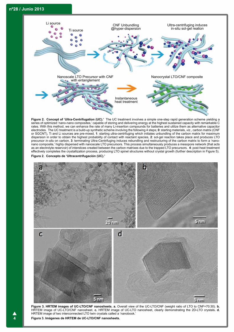
Figure 4. TEM observations of SGCNT and UC-LTO/SGCNT. a. TEM image of a well dispersed and unbundled pristine SGCNT (3-5nm in diameter, specific surface area: 600 m2 g-1), b. Raman spectroscopy of the same SGCNT, showing a fairly high disorder ratio (IG/ID =2.4). This is an indication that the SGCNT used here has abundant anchoring sites for LTO to nucleate. c. HRTEM image of UC-LTO/SGCNT (the weight ratio of LTO to SGCNT= 80:20), exhibiting highly dispersed LTO particles of about 2 to 20 nm in diameter within the SGCNT network. d. HRTEM of UC-LTO/SGCNT (85:15) composite. The high-magnification images confirmed the existence of LTO particles not only within the interstitial spaces of the SGCNT bundles but also inside the single-walled carbon nanotubes in their highly crystalline states. By employing SGCNT in our UC treatment, the ratio of LTO to SGCNT can be maximized to 90% while still maintaining the LTO crystals in its small nucleated and single nanosized dimension. Figura 4. TEM de SGCNT y UC-LTO/SGCNT.
nº28 / Junio 2013
6
and the major phase was the spinel-LTO and carbon matrix.
Figure 3a is a HRTEM image of the obtained LTO/CNF, which displays the high dispersion of LTOs among the CNF network. Figures 3b and 3c are magnified high-resolution images that show planar LTO crystals that are grown two-dimensionally on the CNF. These images demonstrate that the 2D LTO-nanosheet is nucleated and developed on the CNF and is firmly attached before the annealing process. As a result of the fast Fourier-transform (FFT) analysis on TEM images, the lattice of the LTO crystals was composed with d spacing of 4.81 Å, which indicates that it is of the spinel (111) plane. By shortening the annealing process, the (111) plane is able to develop both at a rapid pace and in shape with its surrounding carbon matrix. This can be clearly observed in Figure 3c. The direction of the 2D-LTO crystals follows the contour of the CNF matrix to the extent that a very peculiar structure of two interconnected LTO nanosheets in the shape of an open book was formed (Figure 3d). This ‘nanobook’ of folded LTO/CNF layers suggests that the (111) plane of the LTO nanosheet rapidly changed its direction of growth by about 120 degrees in shape with the contour of the its attached CNF matrix.
5. nc-LTO Composited with SGCNT Interstitials and Inner TubesWe replaced the CNF with SGCNT, a single-walled carbon nanotube synthesized through a super-
growth method [23,26-28] (Figure 4a) as the matrix for the LTO composite. We expected the SGCNT to be a better supporting material due to its high specific surface area, high elemental purity, and high electrical conductivity [27]. The typical IG/ID ratio of the used SGCNT specifically for the UC-nanohybridization was 2.4, as obtained through Raman spectroscopy (Figure 4b). This indicates that compared to the normal SGCNT (IG/ID is typically 12-14) as reported previously [24] it has a fairly high content of defects acting as optimal anchoring sites for the LTO precursors to nucleate. Figures 4c and 4d show HRTEM images of a high loading LTO/SGCNT (80% LTO) in which highly dispersed LTO particles of about 2 to 20 nm in diameter can be clearly observed in the SGCNT network. In addition, the high-magnification images confirmed the existence of the LTO particles not only within the interstitial spaces of the SGCNT bundles but also inside the tubes in their highly crystalline states (Figure 4d). By employing SGCNT in our UC treatment, the ratio of LTO to SGCNT was increased to 90% while still maintaining the LTO nanocrystals in single digit size. This allows for further enhancement in both energy and power capabilities.
6. Real-Time and In-situ HRTEM Observation of Crystallization ProcessReal-time monitoring of the LTO annealing process was conducted through the use of in-situ HRTEM (Figure 5). A sequence of high-resolution electron micrographs shows the in-situ crystallization of UC-LTO/SGCNT at 670oC. What becomes immediately
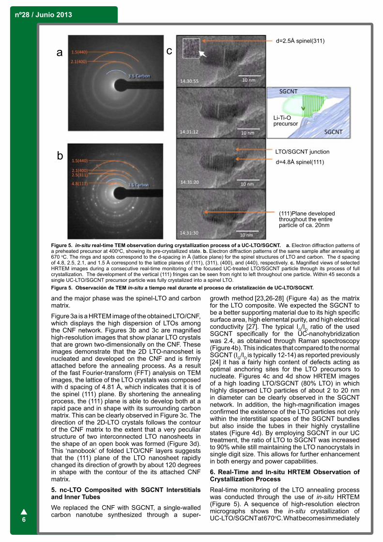
Figure 5. in-situ real-time TEM observation during crystallization process of a UC-LTO/SGCNT. a. Electron diffraction patterns of a preheated precursor at 400oC, showing its pre-crystallized state. b. Electron diffraction patterns of the same sample after annealing at 670 oC. The rings and spots correspond to the d-spacing in Å (lattice plane) for the spinel structures of LTO and carbon. The d spacing of 4.8, 2.5, 2.1, and 1.5 Å correspond to the lattice planes of (111), (311), (400), and (440), respectively. c. Magnified views of selected HRTEM images during a consecutive real-time monitoring of the focused UC-treated LTO/SGCNT particle through its process of full crystallization. The development of the vertical (111) fringes can be seen from right to left throughout one particle. Within 45 seconds a single UC-LTO/SGCNT precursor particle was fully crystalized into a spinel LTO. Figura 5. Observación de TEM in-situ a tiempo real durante el proceso de cristalización de UC-LTO/SGCNT.
Bol. Grupo Español Carbón
7
apparent is the fact that despite crystallization, no growth in size of the LTO was observed. This can be partially explained due to its confinement within the cavity-crated entanglement of the carbon nest as well as other optimal accommodations during the annealing process.
Electron diffraction (ED) analysis was performed during pre-annealing at 400 oC (Figure 5a) and post-annealing at 670oC (Figure 5b) to confirm the formation of the LTO crystal structures and the unchanged presence of the SGCNT. The post-annealing ED pattern seen in Figure 5b clearly indicates the presence of face-centered cubic spinel structures with a Fd mFd 3 space group [17,18].
To further examine the crystallization process, we recorded in real-time the partial crystallization of a LTO particle. Figure 5c shows magnified views of selected HRTEM images during the monitoring period, focusing on one LTO precursor particle for 45 seconds through its process into a fully crystallized spinel structure. Recorded after the formation of roughly half the crystal, the crystallization process proceeded very rapidly with the immediate formation of a fully crystallized particle of 20 nm in diameter within a mere 45 seconds. Approximately every 4.8 Å we observed a new fringe, suggesting the formation of a spinel (111) plane, characterized by its d spacing of 4.8 Å. In its process of development,
we also observed traces of (311) planes with smaller d spacing of 2.5 Å immediately prior to the formation of the (111) planes.
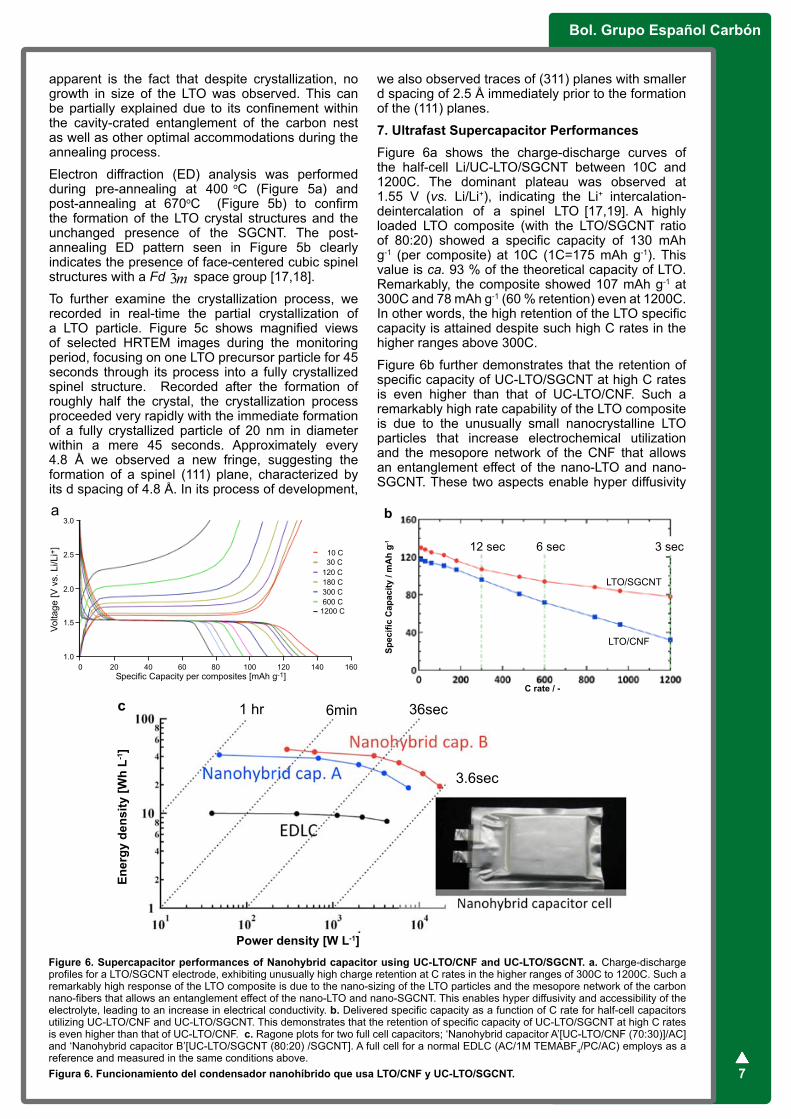
7. Ultrafast Supercapacitor PerformancesFigure 6a shows the charge-discharge curves of the half-cell Li/UC-LTO/SGCNT between 10C and 1200C. The dominant plateau was observed at 1.55 V (vs. Li/Li+), indicating the Li+ intercalation-deintercalation of a spinel LTO [17,19]. A highly loaded LTO composite (with the LTO/SGCNT ratio of 80:20) showed a specific capacity of 130 mAh g-1 (per composite) at 10C (1C=175 mAh g-1). This value is ca. 93 % of the theoretical capacity of LTO. Remarkably, the composite showed 107 mAh g-1 at 300C and 78 mAh g-1 (60 % retention) even at 1200C. In other words, the high retention of the LTO specific capacity is attained despite such high C rates in the higher ranges above 300C.
Figure 6b further demonstrates that the retention of specific capacity of UC-LTO/SGCNT at high C rates is even higher than that of UC-LTO/CNF. Such a remarkably high rate capability of the LTO composite is due to the unusually small nanocrystalline LTO particles that increase electrochemical utilization and the mesopore network of the CNF that allows an entanglement effect of the nano-LTO and nano-SGCNT. These two aspects enable hyper diffusivity
Figure 6. Supercapacitor performances of Nanohybrid capacitor using UC-LTO/CNF and UC-LTO/SGCNT. a. Charge-discharge profiles for a LTO/SGCNT electrode, exhibiting unusually high charge retention at C rates in the higher ranges of 300C to 1200C. Such a remarkably high response of the LTO composite is due to the nano-sizing of the LTO particles and the mesopore network of the carbon nano-fibers that allows an entanglement effect of the nano-LTO and nano-SGCNT. This enables hyper diffusivity and accessibility of the electrolyte, leading to an increase in electrical conductivity. b. Delivered specific capacity as a function of C rate for half-cell capacitors utilizing UC-LTO/CNF and UC-LTO/SGCNT. This demonstrates that the retention of specific capacity of UC-LTO/SGCNT at high C rates is even higher than that of UC-LTO/CNF. c. Ragone plots for two full cell capacitors; ‘Nanohybrid capacitor A’[UC-LTO/CNF (70:30)]/AC] and ‘Nanohybrid capacitor B’[UC-LTO/SGCNT (80:20) /SGCNT]. A full cell for a normal EDLC (AC/1M TEMABF4/PC/AC) employs as a reference and measured in the same conditions above.Figura 6. Funcionamiento del condensador nanohíbrido que usa LTO/CNF y UC-LTO/SGCNT.
b
12 sec 6 sec 3 sec
LTO/SGCNT
LTO/CNF
Spec
ific
Cap
acity
/ m
Ah
g-1
C rate / -
Ener
gy d
ensi
ty [W
h L-1
]
Power density [W L-1]
1 hr 6min 36sec
3.6sec
c
nº28 / Junio 2013
8
and accessibility of the electrolyte, thus enhancing ionic conductivity.
Such LTO composites (both UC-LTO/CNF and UC-LTO/SGCNT) were utilized in combination with two kinds of positive electrodes, viz., activated carbon and SGCNT in creating full laminate cells of ‘Nanohybrid capacitors.’ The Nanohybrid capacitor A and B comprise of [UC-LTO/CNF (70:30)]/1M LiBF4/EC+DMC/AC and [UC-LTO/SGCNT (80:20)]/1M LiBF4/EC+DMC/SGCNT, respectively are tested for their energy-power performances in the same conditions as a reference EDLC (AC/1M LiBF4/PC/AC) cell. Figure 6c shows Ragone plots for the Nanohybrid capacitor cells A, B and EDLC cell obtained from the charge-discharge curves (10-300C). In a low power density range of 0.1-1 kW L-1, the nanohybrid capacitors show energy densities as high as 28-30 Wh L-1, which is a value comparable to that of Li-ion capacitors [6,10]. Even at a high power density of 6 kW L-1, the energy densities of the nanohybrid capacitors remain at 15 Wh L-1, which is double that of conventional electrochemical capacitors. The result reveals that Nanohybrid capacitor A can provide 3 times higher energy than the existing alternatives in both ranges of low power density (0.1-1 kW L-1) and Nanohybrid capacitor B showed 4.5 times higher energy density than the conventional EDLC cell even at high power density of 1-6 kW L-1. It should be noted however that the utilization and a real application of the SGCNT in a large-scale practical supercapacitor device should await its further cost down by nearly a factor of 1/10. However, the Nanohybrid capacitor configuration as a new generation supercapacitor system can be one of the realizable alternatives because the SGCNT is only used in some portion, e.g., 20% within the whole composite electrode materials (LTO/SGCNT=80:20 as shown in Figure 6). This suggests a strong strategy to save the cost of capacitor devices by reducing the dosage of the expensive SGCNT material.
8. OutlookElectrochemical capacitors utilize activated carbons for both positive and negative electrodes that show non-faradaic, double-layer charging-discharging mechanism in symmetric configuration. Thus the electrochemical capacitors are efficient energy storage devices that exhibit long lifespans and extremely rapid charge-discharge characteristics compared with batteries. Today, the capacitor technology is regarded as a promising means and has an additional advantage with increasing effectiveness when combined with solar and wind regenerative energy sources. In recent years, nano-composite battery materials have been vigorously researched in hopes to improve their energy density. Hybridizing battery and capacitor materials overcomes the energy density limitation of existing generation-I capacitors without much sacrificing the cycling performances. Normal battery-capacitor hybrids employ high-energy & sluggish redox electrode and low-energy & fast double-layer electrodes, possibly producing a larger working voltage and higher over-all capacitance. In order to smoothly operate such asymmetric systems, however, the rates of the two different electrodes must be highly balanced. Especially, the redox rates of the battery electrodes must be substantially increased to the levels of double-layer process. In this report,
we attempt to identify the essential issues for the realizable hybrids and suggest ways to overcome the rate enhancement by exemplifying ultrafast performance of the Li4Ti5O12 nanocrystal prepared via a unique in-situ material processing technology under ultra-centrifuging.
9. AcknowledgmentsThe authors are indebted to K. Hata, AIST Japan and S. Iijima (Meijo University, Japan) for supplying SGCNT through NEDO project, Carbon Nanotube Capacitor Project (2006-2011). K.N. is grateful to Y. Gogotsi and B. Dyatkin (Drexel University, U.S.A.) and P. Simon (Paul Sabatier University, France) for valuable discussions. Special thanks to S. Ishimoto (Nippon Chemi-con Corp.) for fabricating test capacitor cells for obtaining supercapacitor performances (Ragone plots).
10. References[1] Simon P, Gogotsi Y. Materials for electrochemical capacitors. Nature Mater. 2008; 7: 845. [2] Chmiola J, Largeot C, Taberna P-L, Simon P, Gogotsi Y. Monolithic Carbide-Derived Carbon Films for Micro-Supercapacitors. Science 2010; 328: 480-483.[3] Gao W, Singh N, Song L, Liu Z, Reddy ALM, Ci L, Vajtai R, Zhang Q, Wei B, Ajayan P M. Direct laser writing of micro-supercapacitors on hydrated graphite oxide films. Nature Nanotechnol. 2011; 6:496-500.[4] Pech D, Brunet M, Durou H, Huang P, Mochalin V, Gogotsi Y, Taberna P-L, Simon P. Ultrahigh-power micrometre-sized supercapacitors based on onion-like carbon. Nature Nanotechnol. 2010; 5:651-654.[5] Lee SW, Yabuuchi N, Gallant BM, Chen S, Kim B-S, Hammond PT, Shao-Horn Y. High-power lithium batteries from functionalized carbon-nanotube electrodes. Nature Nanotechnol. 2010; 5:531-537.[6] Burke A. Ultracapacitors: why, how, and where is the technology. J. Power Sources 2000; 91:37.[7] Pandolfo AG, Hollenkamp AF. Carbon properties and their role in supercapacitors. J. Power Sources 2006; 157: 11.[8] Kötz R, Carlen M. Principles and applications of electrochemical capacitors. Electrochim. Acta 2000; 45:2483-2498.[9] Plitz I, Dupasquier A, Badway F, Gural J, Pereira N, Gmitte, A, Amatucci GG. The design of alternative nonaqueous high power chemistries. Appl. Phys. A 2006; 82:615-626.[10] Naoi K, Simon P. New Materials and New Configurations for Advanced Electrochemical Capacitors. Interface 2008; 17:34-37.[11] Lang X, Hirata A, Fujita T, Chen M. Nanoporous metal-oxide hybrid electrodes for electrochemical supercapacitors. Nature Nanotechnol. 2011; 6:232-236.[12] Wang Q, Wen Z, Li J. Carbon nanotube/TiO2 nanotube hybrid supercapacitors, J. Nanosci. Nanotech. 2007; 7:3328-3331.[13] Zhang W-D, Xu B, Jiang LC. Functional hybrid materials based on carbon nanotubes and metal
Bol. Grupo Español Carbón
9
oxides, J. Mater. Chem. 2010; 20:6383-6391.[14] Naoi K, Ishimoto S, Ogihara N, Nakagawa Y, Hatta S. Encapsulation of Nanodot Ruthenium Oxide into KB for Electrochemical Capacitors. J. Electrochem. Soc. 2009; 156: A52-59.[15] Naoi K, Ishimoto S, Isobe Y, Aoyagi S. High-rate nano-crystalline Li4Ti5O12 attached on carbon nano-fibers for hybrid supercapacitors. J. Power Sources 2010; 195:6250-6254.[16] Naoi K. Nanohybrid Capacitor: The Next Generation Electrochemical Capacitors. Fuel Cells 2010; 10:825-833.[17] Ohzuku T, Ueda A, Yamamoto N. Zero-Strain Insertion Material of Li[Li1/3Ti5/3]O4 for Rechargeable Lithium Cells. J. Electrochem. Soc. 1995; 142:1431-1435.[18] Thackeray MM. Structural Considerations of Layered and Spinel Lithiated Oxides for Lithium Ion Batteries. J. Electrochem. Soc. 1995; 142: 2558-2563.[19] Jansen AN, Kahaian AJ, Kepler KD, Nelson PA, Amine K, Dees DW, Vissers DR. Development of a high-power lithium-ion battery. J. Power Sources 1999; 81-82:902-905.[20] Scharner S, Weppner W, Schmind-Beurmann P. Evidence of Two-Phase Formation upon Lithium Insertion into Li1.33Ti1.67O4 Spinel J. Electrochem. Soc. 1999; 146: 857-861.[21] Shu, J. Study of the Interface Between Li4Ti5O12 Electrodes and Standard Electrolyte Solutions in 0.0-5.0 V. Electrochem. and Solid-State Letters 2008; 11:A238-240.[22] Amatucci, G. G., Badway, F., Pasquier, A. D. and Zheng, T. An Asymmetric Hybrid Nonaqueous Energy Storage Cell. J. Electrochem. Soc. 2001; 148:A930-939.
[23] Zou JH, Sui ZJ, Li P, Chen D, Dai YC, Yuan WK. Structural characterization of carbon nanofibers formed from different carbon-containing gasses. Carbon 2006; 44: 3255-3262.[24] Hata K, Futaba DN, Mizuno K, Namai T, Yumura M, Iijima S. Water-Assisted Highly Efficient Synthesis of Impurity-Free Single-Walled Carbon Nanotubes. Science 2004; 306: 1362-1367.[25] Yuge R, Miyawaki J, Ichihashi T, Kuroshima S, Yoshitake T, Ohkawa T, Aoki Y, Iijima S, Yudasaka M. Highly Efficient Field Emission from Carbon Nanotube−Nanohorn Hybrids Prepared by Chemical Vapor Deposition. ACS Nano 2010; 4:7337-7343.[26] Hiraoka T, Izadi-Najafabadi A, Yamada T, Futaba DN, Yasuda S, Tanaike O, Hatori H, Yumura M, Iijima S, Hata K. Compact and Light Supercapacitor Electrodes from a Surface-Only Solid by Opened Carbon Nanotubes with 2 200 m2 g−1 Surface Area. Adv. Func. Mater. 2010; 20:422-428.[27] Izadi-Najafabadi A, Futaba DN, Iijima S, Hata K. Ion Diffusion and Electrochemical Capacitance in Aligned and Packed Single-Walled Carbon Nanotubes. J. Am. Chem. Soc. 2010; 132:18017-18019.[28] Kamino T, Saka H. A newly developed high-resolution hot stage and its application to materials characterization. Microsc. Microanal. Microstruct. 1993; 4:127-135.[29] Takai S, Kamata M, Fujiine S, Yoneda K, Kanda K, Esaka T. Diffusion coefficient measurement of lithium ion in sintered Li1.33Ti1.67O4 by means of neutron radiography. Solid State Ionics 1999; 123: 165-172.[30] Chen CH, Vaughey JT, Jansen AN, Dees DW, Kahaian AJ, Goacher T, Thackeray MM. Studies of Mg-Substituted Li4–xMgxTi5O12 Spinel Electrodes (0≤x≤1) for Lithium Batteries. J. Electrochem. Soc. 2001; 148: A102-104.

nº28 / Junio 2013
10
AbstractOne option to optimize carbon materials for supercapacitor applications is the generation of surface functional groups that contribute to the pseudocapacitance without losing the designed physical properties. This requires suitable functionalization techniques able to selectively introduce a given amount of electroactive oxygen groups. In this work, the influence of the chemical and electrochemical oxidation methods, on the chemical and physical properties of a zeolite templated carbon (ZTC), as a model carbon material, have been studied and compared. Although both oxidation methods generally produce a loss of the original ZTC physical properties with increasing amount of oxidation, the electrochemical method shows much better controllability and, unlike chemical treatments, enables the generation of a large number of oxygen groups (O = 11000- 3300 µmol/g), with a higher proportion of active functionalities, while retaining a high surface area (ranging between 1900-3500 m2/g), a high microporosity and an ordered 3-D structure.
ResumenUna posibilidad para optimizar los materiales carbonosos para su aplicación en supercondensadores es la generación de grupos funcionales que contribuyan a la pseudocapacidad sin perder las propiedades físicas iniciales. Esto requiere de técnicas de funcionalización adecuadas, capaces de introducir selectivamente una determinada cantidad de grupos oxigenados electroactivos. En este trabajo, se han estudiado y comparado los efectos de los métodos de oxidación química y electroquímica en las propiedades químicas y físicas de un material carbonoso preparado mediante el uso de una zeolita Y como plantilla (en inglés, zeolite templated carbon (ZTC)). Aunque de forma general ambos métodos dañan las propiedades originales del ZTC, el método electroquímico muestra un mayor control que, a diferencia de los tratamientos químicos, permite la generación de una gran cantidad de grupos oxigenados (O = 11000- 3300 µmol/g), con una mayor proporción de grupos activos, manteniendo al mismo tiempo una elevada área superficial (entre 1900-3500 m2/g), una elevada microporosidad y una estructura 3-D ordenada.
1. IntroductionSupercapacitors are already a sufficiently developed technology, with growing range of applications, that in a few more years will become a mainstream technology alongside batteries [1,2]. However, in order to compete with or assist batteries in some applications, the energy density of supercapacitors needs to be increased. In principle, this can be done by widening the stability potential window of the electrolyte and/or the electrode material,
or by increasing the capacitance of this last one. One of the most promising approaches to reach high capacitances is to combine high-surface area carbon materials, the so called electrochemical double-layer (DL) capacitors, with highly-dispersed electroactive materials, like metal oxides and/or conductive polymers, which can exhibit a large pseudocapacitance contribution [1-3]. Another alternative is to increase the pseudocapacitance contribution of carbon materials by increasing the amount of oxygen functional groups.
Regarding this approach, the design of the carbon material as well as the employment of a suitable technique for their functionalization are considered of utmost importance to achieve an optimum supercapacitor performance. First, the combination of an accessible high surface area with both a tailored and ordered pore network may result in a high double-layer capacitance contribution and an excellent rate performance, respectively [1,2]. Second, among the different surface groups, the phenol, carbonyl/quinone and/or anhydride oxygen-based functionalities have been found to actively participate in pseudocapacitive reactions [1,2,4]. Consequently, the modification technique may play a key role, since it is required to show a high efficiency and selectivity to introduce homogeneously the maximum amount of active groups, but at the same time, it must minimize any possible damage of the designed structural properties.
Considering the unique structure of zeolite template carbon (ZTC) [5-7] for fundamental research (as a model material) (Fig. 1a) and/or for potential application as electrode for electrochemical capacitors [8,9], in this work the chemical and electrochemical [10,11] oxidations of ZTC have been studied in order to compare their suitability and advantages for the control of chemical and physical properties of carbon materials that remarkably influence their capacitance performance.
2. ZTC oxidation experimentsZTC was prepared using zeolite Y as a hard template by the method reported elsewhere [5,7]. A squared-molded ZTC paste (0.1 g and 3 cm2 geometric area) was prepared, without binder, by vacuum filtration of an aqueous ZTC suspension through a 0.5 μm pore-size hydrophilic membrane filter. Next, the ZTC paste on the membrane filter was pressed against a Ti/ RuO2 mesh anode and then sandwiched with another membrane filter by thermal sealing (“membrane basket”) (Fig. 1b). The thickness of the carbon material was ca. 1.5 mm.
The ZTC electroxidation was performed anodically by galvanostatic polarization (current = 2-50 mA) at 25 ºC, in a conventional three-electrode electrochemical cell, for different times (1-36 h) in three electrolytes:
Tailoring the Surface Chemistry of Zeolite Templated Carbon by Electrochemical Methods
R. Berenguer1,*, E. Morallón2, D. Cazorla-Amorós2, H. Nishihara3, H. Itoi3, T. Ishii3, T. Kyotani3
1Department of Chemical Engineering, School of Industrial Engineering, University of Malaga, Campus de Teatinos s/n, 29071 Malaga, Spain.2Instituto Universitario de Materiales de Alicante. Universidad de Alicante. Apdo. 99. E-03080 Alicante, Spain.3Institute of Multidisciplinary Research for Advanced Materials. Tohoku University, Sendai 980-8577, Japan.
Bol. Grupo Español Carbón
11
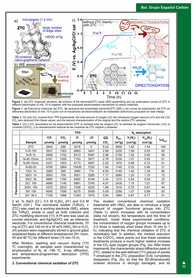
2 wt. % NaCl (Cl–), 0.5 M H2SO4 (H+) and 0.5 M NaOH (OH–). The membrane basket (Ti/RuO2 + ZTC) was used as a working electrode (WE), where the Ti/RuO2 anode is used as both collector and ZTC modifying electrode [11]. A Pt wire was used as counter electrode, and Ag/AgCl/Cl- sat. as reference electrode. For conventional chemical treatments, 70 mg of ZTC and 140 ml of a 30 wt% HNO3 (N) or H2O2 (H) solution were magnetically stirred in ground glass stoppered flasks at different temperatures (R= room, 45 and 80 ºC) for different times (15 min-15 h).
After filtration, washing and vacuum drying (110 ºC overnight), all samples were characterized by physisorption of N2 at -196 ºC, X-ray diffraction, and temperature-programmed desorption (TPD) experiments.
3. Conventional chemical oxidation of ZTC
The studied conventional chemical oxidation treatments with HNO3 are able to introduce a large amount of oxygen functional groups into ZTC (Table 1), which increases with its concentration (data not shown), the temperature and the time of treatment. Under these experimental conditions, the concentration of oxygen groups increases up to 2-3 times in relatively short times (from 15 min to 1 h), indicating that the chemical oxidation of ZTC is remarkably fast. In addition, the marked reduction in the CO/CO2 ratios points out that these oxidative treatments produce a much higher relative increase in the CO2-type oxygen groups (Fig. 2a). After these treatments, the characteristic sharp diffraction peak of ZTC, related to the well-defined (111) planes of zeolite Y employed in the ZTC preparation [5,6], completely disappears (Fig. 2b), so that the 3D-dimensionally ordered structure is strongly damaged, and its
Figure 1. (a) ZTC molecular structure, (b) scheme of the electrode/ZTC paste (WE) assembling and (c) polarization curves of ZTC in different electrolytes (5 mA, 15 h) together with the proposed electroxidation mechanism of carbon materials.Figura 1. (a) Estructura molecular del ZTC, (b) esquema del ensamblaje electrodo/ZTC (WE) y (c) curvas de polarización del ZTC en diferentes electrolitos (5 mA, 15 h) junto con el mecanismo de electroxidación de materiales carbonosos propuesto en este trabajo.
TPD N2 adsorption
SampleCO
μmol/gCO2
μmol/gO
μmol/g∆O
μmol/gCOCO2
SBET
(m2/g)VT(N2)
(cm3/g)VDR(N2)(cm3/g)
%SBET
ZTC 2644 286 3216 0 9.24 3650 1.63 1.54 100
Che
mic
al
H-R-15h 3937 1363 6663 3447 2.89 2200 1.06 0.93 60N-R-1h 4909 1702 8313 5097 2.88 2150 1.02 0.90 59
N-45-15min 4181 1506 7193 3977 2.78 2230 1.07 0.93 61N-80-15min 4327 1923 8173 4957 2.25 1870 0.88 0.72 51
N-80-2h 4708 2864 10436 7220 1.64 1140 0.52 0.46 31
Elec
troc
hem
ical
10Cl– 1h 3260 365 3990 774 8.93 3140 1.42 1.34 8650Cl– 1h 5083 709 6501 3285 7.17 2680 1.25 1.16 7350Cl– 3h 5880 1760 9400 6184 3.34 1210 0.54 0.50 335Cl– 15h 4669 1146 6961 3745 4.07 2430 1.15 1.01 67
5OH– 15h 3372 2033 7438 4222 1.66 1610 0.72 0.67 445H+ 15h 6095 1090 8275 5059 5.59 2290 1.07 0.89 632H+ 36 h 7159 1966 11091 7875 3.64 1860 0.87 0.77 51
Table 1. CO and CO2 evolved from TPD experiments; the total amount of oxygen (O); the introduced oxygen amount (∆O) and the CO/CO2 ratio deduced from these values; and the textural characterization of the original and the oxidize ZTC samples.Tabla 1. CO y CO2 desorbidos en los experimentos DTP; la cantidad total de oxígeno (O); la cantidad de oxígeno introducido (∆O); el cociente CO/CO2; y la caracterización textural de las muestras de ZTC original y oxidadas.
a)
b) WE assembling
c)
Time (h)
INDIRECTOXIDATION
DIRECTOXIDATION
micropores (1.2 nm)
large numberof edge sites
E (V
) vs.
Ag/
AgC
I/CI s
atthermalsealing
membranebasket
3D-orderednano-graphene network
ZTC
ZTC
without ZTC (blank)with ZTC

nº28 / Junio 2013
12
surface area and volume of micropores remarkably decrease (Table 1). This may cause a decline in the capacitance performance. The oxidation with H2O2 solutions (results not shown) involves slower processes and, as a result, the achieved oxidation degrees are lower and limited.
4. Electrochemical oxidation of ZTCZTC was subjected to anodic polarization under different conditions of electrolyte, current and time (Table 1). The interpretation of the polarization curves of ZTC (see example in Fig. 1c) provides, for the first time, a clear experimental evidence of the previously proposed [10,11] direct and indirect electroxidation pathways involved in the proposed general electroxidation mechanism. Considering this mechanism, the following four different behaviors have been distinguished: at lower currents (up to 10 mA), the electrode potential slowly increases with time and it remains below the high constant potentials, assigned to the electrogeneration of oxidizing species from electrolyte, for much longer time, so that ZTC may be electroxidized only by direct polarization for longer time (direct oxidation). In this case, the oxidation is much slower, and a considerably larger proportion of CO-evolving groups (Fig. 2c) (higher CO/CO2 ratios) is achieved, despite the high oxidation degrees (Table 1). This kind of groups corresponds to phenol, carbonyl/quinone and/or anhydride functionalities, which have been found electroactive for pseudocapacitive reactions [1,2,4]. In addition, the oxidized carbon materials retain quite good structural and textural properties (Table 1 and Fig. 2c and d), what is highly beneficial for supercapacitor applications. If the low-current treatment is prolonged (for example at 5 mA, Fig. 1c), an intermediate behavior, with a different contribution
of both direct and indirect oxidation pathways, is observed (mixed oxidation).
On the contrary, at higher currents (above 10 mA), the electrode quickly reaches the high constant potentials necessary to generate oxidizing species (figure not shown). During the initial stage of the process (up to 1 h), the still low concentration of oxidizing species results in oxidized materials with still high CO/CO2 ratios and good physical properties (Table 1) (soft indirect electroxidation). If the time of polarization is prolonged under these conditions (Table 1), the introduced oxidation degree and the structural damage are even higher than those observed with the most aggressive chemical treatments (strong indirect electroxidation). Under these last conditions, the indirect contribution governs the electroxidation process, approaching it to a chemical one.
5. Influence of the oxidation methodAlthough the surface area (%SBET) and the structural order (%IXRD) remaining after the oxidation treatments generally decrease with the amount of introduced oxygen (ΔO), a strong influence of the oxidation method can be clearly observed (Fig. 3a). Thus, comparing for similar or higher amounts of introduced oxygen (ΔO), the electrochemically oxidized samples under direct, mixed or soft-indirect conditions exhibit much better structural properties than those produced by chemical treatments, obtaining oxidized-ZTC samples with unique properties: VDR(N2) = 0.9-1.4 cm3/g, SBET= 1900-3100 m2/g, O = 11000-4000 μmol/g, with a large amount of CO-evolving groups and an extraordinary long-range ordered structure; that cannot be prepared from other carbons nor by treating ZTC with conventional chemical methods.
Figure 2. CO2 and CO evolutions from TPD experiments (a,c) and X-ray diffractogramms (inset: magnified (111)-region) (b,d) for the pristine ZTC and the chemically- (a,b) or electrochemically-treated (c,d) ZTC samples under different conditions.Figura 2. Desorción de CO2 y CO en los experimentos DTP (a,c) y los difractogramas de rayos X (recuadro: región (111) magnificada) (b,d) de las muestras de ZTC original y las tratadas químicamente (a,b) o electroquímicamente (c,d) en diferentes condiciones.
(b)(a)
(d)(c)
CO
2 or C
O (µ
mol
min
-1 g
-1)
CO
2 or C
O (µ
mol
min
-1 g
-1)
Temperature (ºC)
Temperature (ºC)

Bol. Grupo Español Carbón
13
As observed in the Fig. 3b, the success of a given oxidation treatment on preserving the original structural properties of ZTC seems to be closely related to the nature of the introduced oxygen groups, i.e. the CO/CO2 ratios. According to the previously proposed oxidation mechanism for GAC [11], in which CO evolving groups may be formed on free surface sites whereas CO2-evolving groups would be formed by the oxidation of the existent or fresh CO-evolving groups, the higher CO/CO2 ratios obtained when the direct oxidation prevails, suggest that it favors oxidation attack to free sites and, therefore, a less aggressive and more controlled oxidation than that produced by oxidizing species in the chemical or the electrochemical indirect one, which must be very fast and less selective to attack any site of the ZTC structure to produce an overall higher proportion of CO2-evolving groups and a larger number of defects and structural distortions. This must be due to a much greater control of the kinetics of the electroxidation processes, which could permit a gradual generation of the reactants and a preferential oxidative attack to the most reactive sites, preserving the original nanographene structure of the ZTC in a greater extent (Fig. 3b).
6. ConclusionsThe observed physical fragility of ZTC towards the
incorporation of oxygen functionalities highlights the need for the development of more controllable oxidation methods. In this work, the electrochemical modification technique has been proved to be more adequate for tailoring the surface chemistry of ZTC and a promising tool for designing new carbon materials for potential application in supercapacitors. The reasons for the better performance of the electrochemical method can be found on the better controllability of the oxidation kinetics by adjusting the relative participation of the direct and indirect oxidation pathways. The anodic polarization of ZTC in H2SO4 at low currents, where the direct oxidation pathway governs the oxidation process, are the better electrochemical conditions to control the surface chemistry of ZTC, i.e. to obtain highly oxidized ZTC samples (higher efficiency) with a larger proportion of pseudocapcitive-active oxygen groups (higher selectivity) and a lower structural damage.
AcknowledgementsFinancial support by the MINECO and FEDER for the joint Spanish-Japanese project (PRI-PIBJP-2011-0766) and MAT2010-15273 and CTQ2012-31762 projects, by Generalitat Valenciana (PROMETEO/2009/047), as well as the Japanese Ministry of Education, Science, Sports and Culture, for the Grant-in-Aid for young scientists (A) (23685041)
Figure 3. (a) Influence of the oxidation method on the N2 adsorption isotherms (-196ºC) and the (111) diffraction peaks for similar amounts of introduced oxygen (ΔO); (b) Percentages of the specific surface area (%SBET) or the intensity of the (111) diffraction peak (%IXRD) with respect to the original ZTC remaining after different oxidation treatments as a function of the CO/CO2 ratios.Figura 3. (a) Influencia del método de oxidación en las isotermas de adsorción de N2 (-196ºC) y los picos de difracción (111) para cantidades similares de oxígeno introducido (ΔO); (b) Porcentajes del área superficial específica (%SBET) o de la intensidad del pico de difracción (111) (%IXRD), con respecto a los del ZTC original, que permanecen tras los diferentes tratamientos de oxidación en función de los cocientes CO/CO2
CO/CO2 CO/CO2
(b)
(a)
V [m
l (ST
P)/g
]%
S BET
(OR
IGIN
AL)
%IXR
D (OR
IGIN
AL)

nº28 / Junio 2013
14
are gratefully acknowledged.
References[1] Simon P, Gogotsi Y. Materials for electrochemical capacitors. Nat Mater 2008;7(11):845-54.[2] Inagaki M, Konno H, Tanaike O. Carbon materials for electrochemical capacitors. J Power Sources 2010;195(24):7880-7903.[3] Zhao X, Mendoza-Sánchez B, Dobson PJ, Grant PS. The role of nanomaterials in redox-based supercapacitors for next generation energy storage devices. Nanoscale 2011;3:839-855.[4] Bleda-Martínez MJ, Lozano-Castelló D, Morallón E, Cazorla-Amorós D. Linares-Solano A. Chemical and electrochemical characterization of porous carbon materials. Carbon 2006;44(13):2642-51.[5] Ma ZX, Kyotani T, Tomita A. Preparation of a high surface area microporous carbon having the structural regularity of Y zeolite. Chem Commun 2000;(23);2365–6.[6] Matsuoka K, Yamagishi Y, Yamazaki T, Setoyama N, Tomita A, Kyotani T. Extremely high microporosity and sharp pore size distribution of a large surface area carbon prepared in the nanochannels of zeolite Y. Carbon 2005;43(4):876-9.[7] Nishihara H, Yang QH, Hou PX, Unno M, Yamauchi S, Saito R et al. A possible buckybowl-like structure of zeolite templated carbon. Carbon 2009:47(5);1220-30.[8] Itoi H, Nishihara H, Kogure T, Kyotani T. Three-Dimensionally Arrayed and Mutually Connected 1.2-nm Nanopores for High-Performance Electric Double Layer Capacitor. J Am Chem Soc 2011;133(5):1165-67.[9] Nishihara H, Kyotani T. Templated Nanocarbons for Energy Storage. Adv Mater 2012;24(33):4473-98.[10] Berenguer R, Marco-Lozar JP, Quijada C, Cazorla-Amorós D, Morallón E. Effect of electrochemical treatments on the surface chemistry of activation carbon. Carbon 2009;47(4):1018–27.[11] Berenguer R, Marco-Lozar JP, Quijada C, Cazorla-Amorós D, Morallón E. A comparison between oxidation of activation carbon by electrochemical and chemical treatments. Carbon 2012;50(3):1123–34.

Bol. Grupo Español Carbón
15
AbstractMesoporous carbons (MPCs) with large specific surface area are synthesized by the heat-treatment and subsequent acid treatment of magnesium citrate. The MPCs obtained are examined as electrode materials for electric double layer capacitor and show the huge gravimetric capacitance with superior rate performance in sulphuric acid electrolyte. The MPCs also realize the larger capacitance than conventional activated carbon in organic electrolyte and extraordinary high retention of capacitance at very low temperature, such as 80% of room temperature value at -60 °C.
ResumenSe han sintetizado carbones mesoporosos (MPCs) con elevadas superficies específicas mediante tratamiento térmico y posterior tratamiento ácido de citrato de magnesio. Los MPCs obtenidos se han estudiado como electrodos para condensadores de doble capa eléctrica. Estos materiales presentan una capacidad gravimétrica muy elevada y una velocidad de carga-descarga alta en medio ácido sulfúrico. Los MPCs también poseen valores de capacidad en electrolito orgánico mayores que los carbones activados convencionales y presentan una retención de capacidad extraordinariamente alta a muy bajas temperaturas (a una temperatura de -60ºC se obtiene una retención de capacidad en torno al 80% con respecto a la capacidad medida a temperatura ambiente).
1. IntroductionElectric double layer capacitor (EDLC) using carbon electrodes have been anticipated for the future applications, such as power assistance in hybrid electric vehicle, and load levering for pulsed current change in power generator using renewable energy, in which the storage device is required to work with a large and instantaneously fluctuating electric current flow. High surface area carbons are employed for the electrode materials of EDLC to store energy in the electric double layer, and the control of pore size distribution of its carbons is recognized to be one of the most important factors to improve the performance of produced devices [1-3].
Recently, MgO template method has been developed to synthesize mesoporous carbons (MPCs) with high specific surface area (more than 1500 m2/g) by simple carbonization of mixture of carbon precursor compound and MgO powder [4, 5]. We found that the carbonization of pure magnesium citrate gave the formation of high surface area MPCs without conventional activation process and those carbons showed superior capacitive behaviour in both aqueous and nonaqueous electrolytes.
2. Synthesis and pore structure of MgO templated carbonsFig.1 shows the synthesis steps and the schematic model of mesoporous carbons from magnesium citrate. Reagent grade of Mg-citrate (Mg3(C6H5O7)2•9H2O)
Synthesis of MgO templated mesoporous carbons and its use for capacitor electrodeSíntesis de carbones mesoporosos mediante el método de plantilla con MgO para su uso como electrodos de condensadores
Yasushi Soneda* and Masaya KodamaEnergy Technology Research Institute, National Institute of Advanced Industrial Science and Technologies (AIST), 16-1 Onogawa, Tsukuba, Ibaraki 305-8569, Japan.*Corresponding author: [email protected]
Figure 1. The synthesis step and the structural model of mesoporous carbons (MPCs) from magnesium citrate.Figura 1. Proceso de síntesis y modelo estructural de carbones mesoporosos preparados a partir de citrato de magnesio.

nº28 / Junio 2013
16
was heat-treated using a horizontal furnace at 800 ºC in nitrogen flow for 1hr (heating rate of 5°C/min). Carbonized solid was immersed into 6 mol/dm3 HCl for 25 hr to dissolve MgO particles in products and washed with distilled water. According to above simple processes, MPCs with mesopores with narrow distribution which reflects the elimination of MgO particles (template) could be obtained. The organic ligand, citrate, in precursor compound resulted in the formation of carbon skeleton in MPCs with markedly developed micropores.
As the same procedure, mixtures of Mg-citrate with several kinds of organic compounds, such as citric acid, magnesium myristate and so on, were used as precursors to control the pore structure (pore size and distribution) in products. By additing the prescribed amount of melamine (C3H6N6) monomer in precursor Mg-citrate, the nitrogen enriched MPCs have been synthesized.
Fig.2 compares the N2 adsorption-desorption isotherm at 77K on MPC from Mg-citrate and commercial activated carbon for EDLC and the BJH analysis of those curves. Both samples show the steep increase of adsorption at very low pressure which indicates the development of micropore. MPC shows additionally large adsorption up to 0.4 of relative pressure, which corresponds to the distribution from small mesopore region. The diference in isotherm of both samples is reflected well in pore size distribution from BJH analysis (Fig.2b). The specific surface area (BET) of MPC exceeded 2000m2/g and mesopore volume reached 65% of total pore volume (Table 1).
3. MPC electrodes in aqueous electrolyte The capacitive characteristics of MPCs obtained from the mixtures of Mg-citrate and different amount of citric acid were examined in 40% sulphuric acid electrolyte (Fig. 3). The gravimetric capacitance from 10th discharge curve for MPCs (less than 50 wt% of citric acid in precursor) exceeded 400 F/g at the
galvanostatic discharge current density between 0.04 and 1.0 A/g. Especially, the value at 1.0 A/g of current density is quite large and implies the preferable capacitance retention with high rate (current density) usage. The large value of gravimetric capacitance from those carbons could be attributable to the high surface area exceeding 2000 m2/g and the value of areal capacitance is the order of 0.2 F/m2, not very far from the one of the conventional activated carbons. The favourable rate performance is considered due to the large contribution of mesopores to the total pore volume and narrow distribution of them, since the developed mesopores with suitable size results the fast transportation of ions from bulk to solid-electrolyte interface at micropore surface.
Figure 3. Dependence of gravimetric capacitance of MPCs synthesized from Mg-citrate with citric acid (0-90 wt.% in precursor) on discharge current.Figura 3. Dependencia de la capacidad de MPCs sintetizados a partir de citrato de magnesio y con la adición de ácido cítrico (0-90% en peso en precursor) con la corriente de descarga.
Figure 2. Nitrogen adsorption-desorption isotherm at 77K on MPC from Mg-citrate and commercial activated carbon for EDLC and the BJH analysis of those curves.Figura 2. Isotermas de adsorción-desorción de nitrógeno a 77 K de MPC preparado a partir de citrato de magnesio y de un carbón activado comercial usado para EDLC y análisis BJH de las curvas.
Table 1. Specific surface area and pore volume of MPC and activated carbon.Tabla 1. Superficie específica y volumen de poros de MPC y del carbón activado.
SBET [m2/g] Vtotal [ml] Vmeso [ml] Vmicro [ml] Vmeso/ Vtotal [%]
MPC (Mg-Citrate) 2085 1.36 0.88 0.48 65Activated Carbon 1453 0.8 0.14 0.66 18
Activated carbon
Mg-citrate-based carbon Mg-citrate-based carbon
Activated carbon
Relative pressure Pore diameter / nm
Ads
orpt
ion
amou
nt /
cm3 (
S.T
.P,)
g-1
dV/d
logD
/cm
3 g-1
(a) (b)
Gra
vim
etric
cap
acita
nce
[F/g
]
Discharge current density [A/g]
500
450
400
350
3000.01 0.1 1

Bol. Grupo Español Carbón
17
4. MPC electrodes in nonaqueous electrolyteFor the electrochemical measurements in nonaqueous electrolyte, the sample MPCs, binder PTFE and carbon black were mixed with the weight ratio of 8:1:1 and formed into a sheet (100 mm thick). Circular electrode materials with 10 mm diameter were stamped out from a sheet and placed in a home-made Al laminate test cell with etched aluminium foil current collector for both sides of electrodes (symmetric capacitor). 1 mol/dm3 TEA-BF4/PC (tetraethyl ammonium BF4 in propylene carbonate) was used as electrolyte. The galvanostatic charge discharge cycling was performed to evaluate the specific capacitance (gravimetric) of EDLC with the current density of 0.2 mA/cm2 between 2.5 and 0 V. The specific capacitance was calculated from the 6th discharge cycles. The measurement was performed between 20 to -80 °C, after the test cell was kept at each temperature for 10hr.
Fig.4 shows the gravimetric capacitance (F/g) of EDLC measured between 20 and -80 °C for the MPCs (TT13 and TT14) with the conventional activated carbon YP17. MPCs showed the larger specific capacitance than YP17 at all the temperatures under this condition. Since YP17 and MPCs have the similar amount of micropore volume which may contribute to form the electric double layer, the micropores in MPCs are used more effectively due to the existence of mesopores. The reduced capacitance of all samples at low temperature may be caused by the increased viscosity of solution and thus decreased ion transfer in the porous channels in solid electrode.
Below -30 °C, the capacitance of YP17 decreased markedly with lowering the temperature. The MPCs, however, kept the capacitance more than 80% of room temperature until -60 °C. This observation is considered to be that the important amount of mesopore volume in TT13 and TT14 could help the ions transfer from the bulk to the micropore surface even at low temperature.
Figure 4. Gravimetric capacitance at low temperature using laminate cell with Mg-citrate derived mesoporous carbons: TT13 (HTT900), TT14 (HTT1000) and commercial activated carbon YP17.Figura 4. Capacidad gravimétrica a baja temperatura usando una celda plana de aluminio con carbones mesoporosos derivados de citrato de magnesio: TT13 (HTT900), TT14 (HTT1000) y el carbón activado comercial YP17.
5. ConclusionsMgO templated carbons (MPCs) which possessed the specific surface area exceeding 2000 m2/g with large contribution of mesopore reaching 65% of total pore volume were synthesised by the heat treatment of magnesium citrate and the subsequent washing out of MgO particles. The MPCs showed the quite large capacitance with preferable rate dependence in sulphuric acid electrolyte. The MPCs were also showed the extraordinary high capacitance at low temperature by comparison with a conventional activated carbon. Even at -60 °C, MgO carbons showed more than 22 F/g of specific capacitance, corresponding with more than 80% of room temperature, although the activated carbon reduced to 8 F/g, 30% of room temperature. The high performance of MgO templated carbon is considered to be the important amount of mesopore in the materials.
AcknowledgmentA part of this study is supported by Research and Development of Nanodevices for Practical Utilization of Nanotechnology Program in 2008 from the NEDO of Japan. The authors are grateful to Dr. Takahiro Morishita of Toyo Tanso Co. Ltd. for providing mesoporous carbon.
References[1] Endo M, Maeda T, Takeda T, Kim YJ, Koshiba K, Hara H, Dresselhaus MS. Capacitance and pore-size distribution in aqueous and nonaqueous electrolytes using various activated carbon electrodes. J Electrochem Soc 2001; 148:A910-A914.[2] Shiraishi S, Kurihara H, Tsubota H, Oya A, Soneda Y, Yamada Y. Electric double layer capacitance of highly porous carbon derived from lithium metal and polytetra-fluoroethylene. Electrochem. Electrochem Solid-State Lett 2001; 4:A5-A8.[3] Frackowiak E, Jurewicz K, Delpeux S, Béguin F. Nanotubular materials for supercapacitors. J Power Sources 2001; 97-98:822-825.[4] Morishita T, Suzuki R, Nishikawa T, Tsumura T, Inagaki M. Preparation of porous carbons by carbonization of the mixtures of thermoplastic precursors with MgO, TANSO 2005; 219:226-231.[5] Morishita T, Soneda Y, Tsumura T, Inagaki M. Preparation of porous carbons from thermoplastic precursors and their performance for electric double layer capacitors. Carbon 2006; 44:2360-2367.
Gra
vim
etric
cap
acita
nce
[F/g
]
Temperatiure (ºC)
30
25
20
15
10
5
0-80 -30 20
TT13
TT14
YP17

nº28 / Junio 2013
18
AbstractThe electric double layer capacitor (EDLC) is an electrochemical capacitor storing electric energy by charging the electric double layer on the micropores of a nanoporous carbon electrode such as activated carbon. The EDLC has a fast charge-discharge property and excellent cycle life, but its energy density is lower than other electrochemical energy storage devices such as the rechargeable battery. The energy density of the EDLC can be improved by increasing the double layer capacitance and the maximum charging voltage. In this review, the author describes the activated carbon electrodes for use in a durable EDLC for high voltage charging.
ResumenUn condensador de doble capa eléctrica (EDLC) es un condensador electroquímico que almacena energía eléctrica por la carga de la doble capa eléctrica en los microporos de un electrodo de carbón nanoporoso, como puede ser un carbón activado. El EDLC tiene propiedades de carga-descarga rápida y un excelente tiempo de vida al ciclado, pero su densidad de energía es más baja que la de otros dispositivos de almacenamiento de energía electroquímicos, tales como las baterías recargables. La densidad de energía de los EDLC se puede mejorar mediante el aumento de la capacidad de doble capa y del voltaje de carga. En esta revisión, el autor describe las características de electrodos de carbón activado para su uso en EDLC de gran durabilidad en condiciones de elevado voltaje de carga.
1. IntroductionIn recent years, electrochemical capacitors, which have a higher capacitance than conventional
dielectric capacitors (e.g., film capacitor, ceramic capacitor, and electrolytic capacitor) have been the focus as an electric energy storage device with a rapid charge-discharge performance [1]. The EDLC is an electrochemical capacitor based on the dielectric property of the electric double layer at the interface between the electrolyte and a nanoporous carbon electrode, such as activated carbon, as shown in Fig.1. EDLC has been widely used as a power source for electric devices since its commercialization in the 1970s. However, the energy density of the EDLC is lower than that of rechargeable batteries, such as the lithium ion battery, therefore, it should be further improved for energy storage applications. According to the E = CV2 / 2 correlation, the energy density (E) of the EDLC depends on the double layer capacitance (C) of the activated carbon electrode and the maximum applied voltage (V). Many scientists and industries have already made significant efforts to find the optimized pore structure of the activated carbons [2-4], but the approach for improving the energy density of the EDLC only by pore structure design has met some limitations. The typical maximum charging voltage of the commercialized EDLC using an organic electrolyte (e.g., propylene carbonate solution containing an alkylammonium salt) is about 2.5 ~ 2.7 V. The higher voltage charging of the EDLC, such as above 3.0 V, is required to improve the energy density, but it is known to cause a capacitance decline and cycling deterioration due to electrochemical decomposition at the electrode interface [5-7]. There are only a few research examples concerning the improvement of the maximum charge voltage for the EDLC compared to those relating to the change in the capacitance. This review addresses some techniques for carbon electrode enhancement for improving of the maximum voltage of the EDLC.
Highly-Durable Carbon Electrode for Electrochemical CapacitorsElectrodos de Carbón de Alta Duración para Condensadores Electroquímicos
Soshi ShiraishiDivision of Molecular Science, Faculty of Science and Technology, Gunma University, Kiryu, Gunma 376-8515, Japan.
Fig.1 Schematic illustration of electric double layer capacitor (EDLC)Fig.1 Esquema de un condensador de doble capa eléctrica (EDLC)

Bol. Grupo Español Carbón
19
2. Heat-treatment of Activated Carbon [8]The origins of the capacitance decline by high voltage charging are thought to be the electrochemically active sites such as the oxygen-containing functionalities or the defect points (e.g., edge plane) on the activated carbon electrode. The heat-treatment above 1000°C can remove the oxygen-containing functionalities and improve the carbon crystallinity of the micropore walls. Raman spectra (Fig.2) of the heated-activated carbons (phenolic resin based, steam activated) in an inert atmosphere revealed that narrowing of the band width of the G band or D band by increasing the heat-treatment temperature, suggesting a crystallinity improvement. The BET specific surface area, micropore volume, mean micropore width, amount of the oxygen surface functionalities, initial capacitance, and capacitance retention after the durability test (floating condition, 3V/70°C/100 h or 3.5V/60°C/200 h) are summarized in Table 1. The capacitance retention after 3.0V at 70°C for 100h was improved by the heat-treatment, and the maximum retention was obtained at 1500°C. Additionally, the heat-treatment effect is very prominent under the more aggressive condition (3.5V/60°C/200 h). Since most of the oxygen surface functionalities were removed by the heat-treatment, the durable property is due to the deactivation of the electrochemically active site of the oxygen surface functionalities and the crystal defects. However, the higher temperature during the heat-treatment lowered the specific surface area and the micropore volume. This is due to the shrinkage and blocking of the micropores. The initial capacitance, which is related to the specific surface area, also decreased with the increasing heat-treatment temperature. Thus, the heat-treatment of activated carbons, which is very simple and a cheap method, produces the undesired trade-off relationship between the initial capacitance and the capacitance retention.
Fig.2 Raman spectra (532 nm) of original activated carbon (AC) and heated AC (1000 ~ 1700 °C) in inert gas.Fig. 2 Espectros Raman (532 nm) del carbón activado original (AC) y AC tratado (1000 ~ 1700 ° C) en gas inerte.
The effect of the heat-treatment at a higher temperature, such above 2000°C, has attracted interest, but the activated carbons heated above 2000°C show very low capacitances due to complete micropore shrinkage. The author confirmed the heat-treatment effect at high temperature using multi-walled carbon nanotubes (MWCNT) as the
electrode active material for the EDLC. The BET specific surface area, the initial capacitance, and the capacitance retention after the durability test (floating condition, 3V/70°C/100 h or 3.5V/60°C/200 h) are summarized in Table 2.
The MWCNT used for the test (it is the same material as reported in the literature [9]) was thermally stable against the heat-treatment at 2800°C and maintained the tube structure as shown in Fig.3. The MWCNT heated at 2800°C exhibited the perfect capacitance-retention even under the more aggressive conditions (3.5V/60°C/200 h). The capacitance of the MWCNT is not high, but this result should be noted such that the elimination of the active sites is significant for realizing a durable EDLC against high voltage operation.
Fig.3 Transmission electron microscopic (TEM) image of MWCNT heated at 2800 °CFig.3 Imagen de microscopía electrónica de transmisión (TEM) de MWCNT calentados a 2800°C
Nitrogen Doping of Activated Carbon [8]Nitrogen-doped nanoporous carbons, namely, nanoporous carbons containing nitrogen atoms or nitrogen-enriched nanoporous carbons are known to have a higher capacitance compared to the nitrogen-free conventional activated carbons [10-12]. The origin of the high capacitance is still under investigation, but the contribution of the redox (pseudo) capacitance by the nitrogen surface functionalities, the electronic modification of the electrode interface (carrier concentration increase), and the high wettability of the pore walls have been proposed. Thus, the nitrogen-doping of an activated carbon is an attractive technique for increasing the capacitance. The author’s group also focused on the nitrogen doping and determined that it is also effective for improving the durability of the EDLC for the high voltage charging [8]. The nitrogen-doped activated carbons are easily prepared by the heat-treatment

nº28 / Junio 2013
20
Table 1. Pore structure of heated activated carbon (AC) and the durability of EDLC against high voltage charging.Tabla 1. Estructura porosa del carbón activado tratado (AC) y durabilidad de los EDLC para un voltaje de carga elevado.
Sample HTT [°C]
SBET
[m2g-1]Vmicro
[mlg-1]wmicro
[nm]Aco
[mmolg-1]Aco2
[mmolg-1]C0
[Fg-1]Cd(1) / C0
[%]Cd (2)/ C0
[%]AC-original - 2050 0.78 0.98 1.2 0.2 26 81 2AC-1000 1000 1830 0.70 1.00 0.12 0.05 21 84 -AC-1200 1200 1780 0.70 0.94 - - 21 87 -AC-1500 1500 1660 0.63 0.91 0.07 0.02 17 89 58AC-1700 1700 1360 0.52 0.91 - - 13 82 -
Original activated carbon was prepared by carbonization and steam activation of phenolic resin
HTT: Heat-treatment temperature in nitrogen (1000~1200°C, 1 hour) or argon gas (1500~1700°C, 1hour)
SBET: BET specific surface area
Vmicro: Micropore volume
wmicro: Average micropore width
ACO: Desorption amount of CO by TPD analysis (up to 1000°C in He)
ACO2: Desorption amount of CO2 by TPD analysis (up to 1000°C in He)
C0,: Initial capacitance (two-electrode system, 1M (C2H5)3CH3NBF4/propylene carbonate, 80mAg-1, 0 ~ 2.5V, 40°C)
Cd(1) / C0: Capacitance retention by durability test (3V/70°C/100 h)
Cd(2) / C0: Capacitance retention by durability test (3.5V/60°C/200 h)
Table 2. Specific surface area of heated multi-walled carbon nanotube (MWCNT) and the durability of EDLC against high voltage chargingTabla 2. Superficie específica de nanotubos de carbón de pared múltiple tratados (MWCNT) y durabilidad de los EDLC para un voltaje de carga elevado
SampleHTT[°C]
SBET
[m2g-1]C0
[Fg-1]Cd(1) / C0
[%]Cd (2)/ C0
[%]MWCNT (cup-open) - 370 5.1 80 0MWCNT -2800 2800 190 2.7 102 103
MWCNT was prepared by CVD method and oxidized/washed by acid to remove metal catalyst and open the end cup.
HTT: Heat-treatment temperature (1hour) in argon gas
SBET: BET specific surface area
C0,: Initial capacitance (two-electrode system, 1M (C2H5)3CH3NBF4/propylene carbonate, 40°C)
Cd(1) / C0: Capacitance retention by durability test (3V/70°C/100 h)
Cd(2) / C0: Capacitance retention by durability test (3.5V/60°C/200 h)
Table 3 Pore structure of NO-treated activated carbon (AC)Tabla 3 Estructura porosa del carbón activado tratado con NO
SampleSBET
[m2g-1]
Vmeso
[mlg-1]
Vmicro
[mlg-1]
wmicro
[nm]
AC-original 2040 0.43 0.85 1.18
NO-AC 1970 0.43 0.82 1.20
Original activated carbon was prepared by carbonization and steam activation of phenolic resin.
Nitrogen atom was doped to the original AC by heat treatment in He gas containing 2000ppm NO gas at 800°C for 1 hour to prepare NO-AC.
SBET: BET specific surface area
Vmicro: Micropore volume
wmicro: Average micropore width
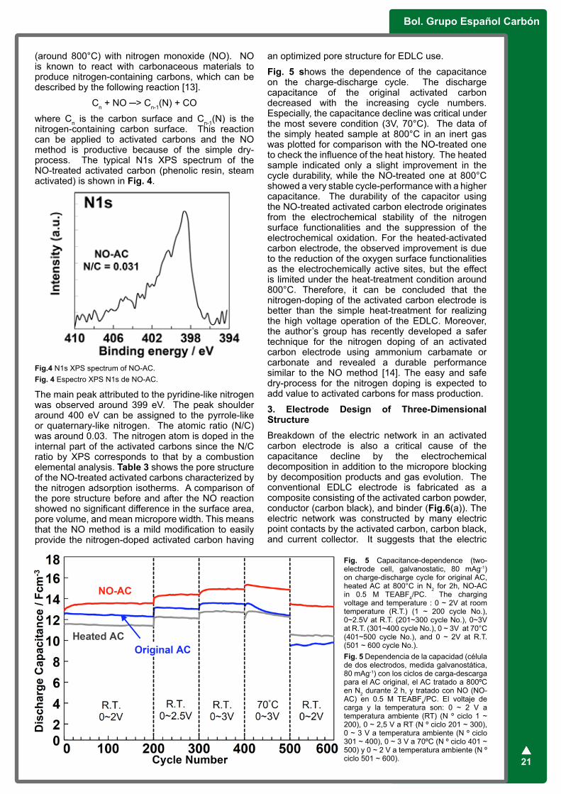
Bol. Grupo Español Carbón
21
(around 800°C) with nitrogen monoxide (NO). NO is known to react with carbonaceous materials to produce nitrogen-containing carbons, which can be described by the following reaction [13].
Cn + NO ─> Cn-1(N) + CO
where Cn is the carbon surface and Cn-1(N) is the nitrogen-containing carbon surface. This reaction can be applied to activated carbons and the NO method is productive because of the simple dry-process. The typical N1s XPS spectrum of the NO-treated activated carbon (phenolic resin, steam activated) is shown in Fig. 4.
Fig.4 N1s XPS spectrum of NO-AC.Fig. 4 Espectro XPS N1s de NO-AC.
The main peak attributed to the pyridine-like nitrogen was observed around 399 eV. The peak shoulder around 400 eV can be assigned to the pyrrole-like or quaternary-like nitrogen. The atomic ratio (N/C) was around 0.03. The nitrogen atom is doped in the internal part of the activated carbons since the N/C ratio by XPS corresponds to that by a combustion elemental analysis. Table 3 shows the pore structure of the NO-treated activated carbons characterized by the nitrogen adsorption isotherms. A comparison of the pore structure before and after the NO reaction showed no significant difference in the surface area, pore volume, and mean micropore width. This means that the NO method is a mild modification to easily provide the nitrogen-doped activated carbon having
an optimized pore structure for EDLC use.
Fig. 5 shows the dependence of the capacitance on the charge-discharge cycle. The discharge capacitance of the original activated carbon decreased with the increasing cycle numbers. Especially, the capacitance decline was critical under the most severe condition (3V, 70°C). The data of the simply heated sample at 800°C in an inert gas was plotted for comparison with the NO-treated one to check the influence of the heat history. The heated sample indicated only a slight improvement in the cycle durability, while the NO-treated one at 800°C showed a very stable cycle-performance with a higher capacitance. The durability of the capacitor using the NO-treated activated carbon electrode originates from the electrochemical stability of the nitrogen surface functionalities and the suppression of the electrochemical oxidation. For the heated-activated carbon electrode, the observed improvement is due to the reduction of the oxygen surface functionalities as the electrochemically active sites, but the effect is limited under the heat-treatment condition around 800°C. Therefore, it can be concluded that the nitrogen-doping of the activated carbon electrode is better than the simple heat-treatment for realizing the high voltage operation of the EDLC. Moreover, the author’s group has recently developed a safer technique for the nitrogen doping of an activated carbon electrode using ammonium carbamate or carbonate and revealed a durable performance similar to the NO method [14]. The easy and safe dry-process for the nitrogen doping is expected to add value to activated carbons for mass production.
3. Electrode Design of Three-Dimensional StructureBreakdown of the electric network in an activated carbon electrode is also a critical cause of the capacitance decline by the electrochemical decomposition in addition to the micropore blocking by decomposition products and gas evolution. The conventional EDLC electrode is fabricated as a composite consisting of the activated carbon powder, conductor (carbon black), and binder (Fig.6(a)). The electric network was constructed by many electric point contacts by the activated carbon, carbon black, and current collector. It suggests that the electric
Fig. 5 Capacitance-dependence (two-electrode cell, galvanostatic, 80 mAg-1) on charge-discharge cycle for original AC, heated AC at 800°C in N2 for 2h, NO-AC in 0.5 M TEABF4/PC. The charging voltage and temperature : 0 ~ 2V at room temperature (R.T.) (1 ~ 200 cycle No.), 0~2.5V at R.T. (201~300 cycle No.), 0~3V at R.T. (301~400 cycle No.), 0 ~ 3V at 70°C (401~500 cycle No.), and 0 ~ 2V at R.T. (501 ~ 600 cycle No.). Fig. 5 Dependencia de la capacidad (célula de dos electrodos, medida galvanostática, 80 mAg-1) con los ciclos de carga-descarga para el AC original, el AC tratado a 800ºC en N2 durante 2 h, y tratado con NO (NO-AC) en 0.5 M TEABF4/PC. El voltaje de carga y la temperatura son: 0 ~ 2 V a temperatura ambiente (RT) (N º ciclo 1 ~ 200), 0 ~ 2,5 V a RT (N º ciclo 201 ~ 300), 0 ~ 3 V a temperatura ambiente (N º ciclo 301 ~ 400), 0 ~ 3 V a 70ºC (N º ciclo 401 ~ 500) y 0 ~ 2 V a temperatura ambiente (N º ciclo 501 ~ 600).

nº28 / Junio 2013
22
network is easily collapsed since the electrical contact at the particle boundary and the interface between the active material layer and the current collector are not mechanically and chemically inert to electrochemical decomposition reactions. Thus, a novel electrode structure unrelated to this problem should be developed. Recently, the author’s group found that a particle-boundary free (seamless) electrode structure [15] and a porous current collector [16] are very effective for improving the durability against high voltage charging. In this section, the author provides an outline of the EDLC performances using the seamless activated carbon electrode (Fig.6(b)) and the foamed aluminum current collector (Fig.6(c)) focusing on the durability against high voltage charging (>3V).
Fig. 6 Schematic model of (a) conventional electrode, (b) seamless activated carbon electrode, and (c) activated carbon electrode using foamed Al as current collector for EDLCFig. 6 Modelo esquemático de (a) electrodo convencional, (b) electrodo de carbón activado sin aglomerante, y (c) electrodo de carbón activado usando espuma de Al como colector de corriente para EDLC.
The seamless activated carbon electrode (16mm diameter disk) was prepared by the carbonization (800 °C) and CO2 activation (850 °C) of the consecutively macroporous phenolic resin matrix called “MICROLIGHT” (mean pore size: 7 μm, commercial product of AION Co., Japan). Fig.7 shows the scanning electron microscopic (SEM) images of the conventional composite electrode, the original MICROLIGHT, and its carbonization/
activation product (seamless activated carbon electrode, carbonization yield: 40%, activation yield: 57%). The typical composite structure consisting of activated carbon grains and carbon black particles was observed in the conventional composite electrode. The SEM image of the MICROLIGHT and its activation product indicated the macroporous structure without particle boundaries and that the macroporous structure was maintained after the CO2 activation process. This seamless activated carbon electrode has the BET specific surface area of 1960 m2g-1, the micropore volume of 0.76 mlg-1, and the mean micropore width of 0.93 nm. This means that the micropores in the seamless electrode are highly developed as well as the conventional activated carbon.
Fig. 7 SEM images (×4000) of (a) conventional activated carbon electrode, (b) original MICROLIGHT (consecutively macroporous phenolic resin), and (c) seamless activated carbon electrodeFig. 7 Imágenes de SEM (× 4000) de (a) electrodo de carbón activado convencional, (b) MICROLIGHT original (resina fenólica macroporosa), y (c) electrodo de carbón activado sin aglomerante.
The foamed Al current collector (mean pore size: 600 μm, commercial product of Mitsubishi Materials Co., Japan) was filled with the activated carbon powder

Bol. Grupo Español Carbón
23
(containing a small amount of carbon black and PTFE binder) to prepare the capacitor test electrode (16mm diameter disk). YP50F (Kuraray Chemical. Co., Japan), which is a typical steam-activated carbon powder for the EDLC, was used as the active material for the foamed Al current collector. YP50F has the BET specific surface area of 1550 m2g-1, micropore volume of 0.60 mlg-1, and mean micropore width of 0.97 nm. The SEM image of the foamed Al and the backscattered electron microscopic (BSE) image of the test electrode are shown in Fig.8.
Fig. 8 (a) SEM image of foamed Al current collector (average pore size: 600 mm) and (b) BSE image of YP50F-filled foamed Al electrodeFig. 8 (a) Imagen de SEM del colector de corriente de espuma de Al (tamaño de poro promedio: 600 mm) y (b) la imagen de BSE del electrodo de espuma de Al relleno de YP50F
The test capacitor cell (two-electrode system) was fabricated by these electrodes, paper-type separator, and organic electrolyte (1.0 M (C2H5)3CH3NBF4
/ propylene carbonate). The capacitance was measured by the galvanostatic method (80mAg-1, 0~2.5 V) at 40°C. The durability test was conducted by the floating condition (3.5 V charging, 100h, 70 °C). The results of the durability test are summarized in Table 4. Both the seamless activated carbon electrode and the YP50F-filled foamed Al electrode indicated very high capacitance retentions (>80%) and only a small increase in the internal resistance during the 3.5 V durability test. The conventional composite activated carbon electrode using YP50F and etched Al foil current collector showed a very low capacitance retention (~10%) and significant change in the internal resistance during the same durability test, therefore it was revealed that the seamless structure or the foamed current collector is very effective in improving the durability of the EDLC against high voltage charging. For the seamless electrode, the excellent durability is postulated to result from alleviating the electrical contact problem caused by the electrochemical decomposition. It is considered that the foamed current collector has the function that the activated carbon particles inside the pores maintain strong contacts to each other to form a stable electric network.
4. ConclusionSome techniques for the activated carbon electrode are reviewed from the viewpoint of the high voltage EDLC operation. The surface modification of the activated carbon electrode (e.g., heat treatment, nitrogen doping) and the three-dimensional electrode structure with a strong electric network (e.g., seamless electrode, formed current collector) are effective for developing a durable electrode against high voltage charging. The former technique is related to the suppression of the electrochemical decomposition and the latter is concerned with the construction of the strong electric network. The combination of these two techniques is also expected to have a synergistic effect. In any case, the important issue is that establishment of a simple and mass-productive method like the methods presented in this review should be necessary for practical use and commercialization.
5. AcknowledgementThis work was partially supported by NEDO and JST of Japan and the “Element Innovation” Project by Ministry of Education, Culture, Sports, Science & Technology in Japan. The author would like to
Table 4 Capacitance and internal resistance of EDLC before and after durability test (floating condition: 3.5V, 100h, 70°C) Tabla 4 Capacidad y resistencia interna del EDLC antes y después del test de durabilidad (condiciones de flotación: 3.5V, 100h, 70°C)
Activated Carbon Al Current CollectorC0
[Fg-1]
Cd/C0
[%]
R0
[W]
DR
[W]Seamless Etched foil 30 80 3 8Powder composite (YP50F) Foamed 26 87 5 15Powder composite (YP50F) Etched foil 25 12 5 38
C0: initial capacitance (two-electrode system, 1M (C2H5)3CH3NBF4/propylene carbonate, 80 mAg-1, 0 ~ 2.5V, 40°C)
Cd/C0: capacitance retention
R0: initial internal resistance
R: increase of internal resistance

nº28 / Junio 2013
24
express sincere appreciation to AION Co. and Mitsubishi Materials Co. for providing MICROLIGHT and foamed Al sheet respectively.
6. References[1] Conway BE. Electrochemical Supercapacitors: Scientific Fundamentals and Technological Applications. Springer 1999.[2] Simon P, Burke A. Nanostructured cabons: double-layer capacitance more. Interface 2008; 17(1): 38–43. [3] Frackowiak E. Carbon materials for supercapacitor application. Phys. Chem. Chem. Phys. 2007; 9(15): 1774–1785.[4] Inagaki M, Konno H, Tanaike O, Carbon materials for electrochemical capacitors. J. Power Sources 2010; 195(24): 7880-7903.[5] Azaïs P, Duclaux L, Florian P, Massiot D, Lillo-Rodenas MA, Linares-Solano A. Peres JP, Jehoulet C, Béguin F. Causes of supercapacitors ageing in organic electrolyte. J Power Sources 2007; 171(2): 1046−1053.[6] Ishimoto S, Asakawa Y, Shinya M, Naoi K. Degradation responses of activated-carbon-based EDLCs for higher voltage operation and their factors. J Electrochem Soc 2009;156(7): A563–71.[7] Cazorla-Amorós D, Lozano-Castelló D, Morallón E, Bleda-Martínez MJ, Linares-Solano A. Shiraishi S. Measuring cycle efficiency and capacitance of chemically activated carbons in propylene carbonate. Carbon 2010; 48(5): 1451−1456.[8] Shiraishi S, Heat-treatment and nitrogen-doping of activated carbons for high voltage operation of electric double layer capacitor. Key Eng. Mater. 2012; 497: 80–86.
[9] Shiraishi S, Kibe M, Yokoyama T, Kurihara H, Patel N, Oya A, Kaburagi Y, Hishiyama Y, Electric double layer capacitance of multi-walled carbon nanotubes and B-doping effect. Appl. Phys. A 2006; 82(4): 585–591.[10] Frackowiak E, Lota G, Machnikowski J, Vix-Guterl C, Béguin F. Optimisation of supercapacitors using carbons with controlled nanotexture and nitrogen content. Electrochim. Acta 2006; 51(11): 2209–2194.[11] Kodama M, Yamashita J, Soneda Y, Hatori H, Kamegaw K, Moriguchi I. Electrochemical capacitance of nitrogen-enriched mesoporous carbon. Chem. Lett. 2006; 35(6): 680–681.[12] Hulicova-Jurcakova D, Kodama M, Shiraishi S, Hatori H, Zhu ZH, Lu GQ, Nitrogen-enriched nonporous carbon electrodes with extraordinary supercapacitance. Adv. Funct. Mater. 2009; 19: 1800–1809. [13] Suzuki T, Kyotani T, Tomita A. Study on the carbon - nitric oxide reaction in the presence of oxygen. Ind. Eng. Chem. Res. 1994; 33(11): 2840–2845.[14] Shiraishi S, Takeda K, Kawaguchi S. Electric double layer capacitor using nitrogen-doped activated carbon electrode prepared by ammonium carbamate. Carbon2012 Extended Abstract; 830.[15] Shiraishi S, Yukiko E, Onda K, Tsukada H. Electric double layer capacitor using seamless activated carbon electrode. Carbon2013 Extended Abstracts; in press.[16] Shiraishi S, Foamed current-collector and functionalized activated-carbon for EDLC. 220th ECS meeting Abstracts 2011; #569.

Bol. Grupo Español Carbón
25
Objectives and noveltyIndustrial and commercial growth in many countries around the world in the past decades has been accompanied by rapid generation of municipal and industrial solid waste, which creates the most serious environmental problems related to landfill such as the generation of leachates during the decomposition process. Among the emerging contaminants that have been detected in landfill leachates, wastewater, ground water and surface water are plastic additives and herbicides with range 0.01 µg/L to 30 mg/L. Phthalic acid (PA), bisphenol A (BPA), and diphenolic acid (DPA) are the most common monomeric plasticizers used to produce plastic material; and 2, 4- dichlorophenoxyacetic acid (2,4-D) and 4-chloro-2-methylphenoxyacetic acid (MCPA) are widely used herbicides in the world. They have potential toxicity towards humans and animals, and are suspected mutagens, carcinogens, and endocrine disruptors even at a low concentration. Numerous studies have been reported that the conventional wastewater treatments are not effective to remove these pollutants, therefore alternative treatments are necessary. The adsorption process and advanced oxidation processes (AOPs) are widely used to eliminate similar compounds from aqueous solution, taking advantage of their respective adsorbent and oxidizing properties. Activated carbon (AC) has been signaled as a promising catalyst of AOPs, however, there are few available data concerning the interaction mechanism that takes place through the AOPs in the presence of AC. With this background, the present work aimed to investigate the elimination of the above selected contaminants present in landfill leachates through different technologies such as: adsorption/bioadsortion on ACs, AOPs based on the use of UV radiation (UV, UV/H2O2, UV/K2S2O8, UV/Na2CO3 and UV/TiO2/AC) and gamma radiation.
ResultsThe overall adsorption rate of selected contaminants on two commercial ACs denominated as S and C
was interpreted using diffusion models (external mass transport, intraparticle diffusion, pore volume diffusion, and surface diffusion) and kinetic models. Results showed that the external mass transport did not affect the overall adsorption rate of these contaminants on AC samples, the contribution of pore volume diffusion represented more than 92% of intraparticle diffusion on both ACs (Figure 1). The kinetic models were satisfactorily fitted to experimental data and the second-order kinetic model was better fitted these data than the first-order kinetic one.
The ACs used in this study had a high adsorption capacity which was largely attributable to dispersion and electrostatic adsorbent-adsorbate interactions. The solution pH had a major effect on PA adsorption on ACs, however, PA adsorption was not affected by the presence of electrolytes (ionic strength) in solution but was enhanced by the presence of microorganisms by around 15%, which was explained by an increase in carbon surface hydrophobicity of the AC due to the production of extracellular polymeric substances by microorganisms adsorbed on AC surface. PA removal varied as a function of the water type, increasing in the order: ground water < surface water ≃ ultrapure water < wastewater. The adsorption yield was much lower in dynamic versus static regime, attributable to difficulties of PA diffusion into the carbon pores and the shorter adsorbent-adsorbate contact time in dynamic regime.
Concerning the AOPs, results showed that UV radiation was not effective to remove these pollutants from the medium, due to their low quantum yield. The addition of radical promoters such as H2O2, K2S2O8, or Na2CO3 markedly increased the effectiveness of UV radiation through the generation of HO●, SO4
●-, or CO3
●-/HCO3● radicals, respectively. The rate
constants of reactions between these radicals and BPA were , , and . The solution pH had a major effect on BPA degradation with these three systems. These oxidation systems showed 100% effectiveness
Thesis Review. Integrated technologies based on the use of activated carbon and radiation to remove contaminants present in landfill leachatesM. M. Abdel daiemPresented: 2012, Inorganic Chemistry Department, Faculty of Science, Granada University, Granada, 18071, Spain.Supervisors: J. Rivera Utrilla, M. Sánchez Polo and R. Ocampo Pérez (Granada University, Spain).
Figure 1. Contribution of pore volume diffusion to intraparticle diffusion at different radial positions, a) PA on carbon C; b) BPA on carbon S.
Time (min) Time (min)0 2000 4000 6000 8000 10000 0 2000 4000 6000 8000 10000
Nap
/(NA
s +
NA
p)
1.00
0.98
0.96
0.94
0.92
Nap
/(NA
s +
NA
p)
1.00
0.99
0.98
0.97
0.96
0.95
(a) (b)

nº28 / Junio 2013
26
to remove BPA from wastewater, due to its large content of natural organic matter. The lowest BPA degradation was detected in ground water due to its higher content of metal species and bicarbonate ions. The mineralization of organic matter was more effective with the UV/K2S2O8 system, followed by UV/H2O2 and UV/Na2CO3 systems. The lowest toxicity of byproducts was reached when using the UV/K2S2O8 system.
The photocatalytic degradation of 2,4-D was investigated by using the integrated UV/TiO2/AC system. Three commercial ACs denominated as S, M, and W were used in this study. Sample W was oxidized with ozone for 30 min and 120 min. Results obtained showed that the presence of AC during the catalytic photodegradation (UV/TiO2) of 2,4-D considerably increased its percentage removal. The highest 2,4-D degradation was obtained in the presence of the ozonated ACs with a high carboxylic groups content. Carboxylic groups in the graphene planes of the activated carbon participate in the additional generation of HO· radicals by interacting with the electrons produced by the UV/TiO2 system. Consequently, the contribution of HO· radicals to the global 2,4-D degradation process is greater at the beginning of the photocatalytic treatment in the presence of ozonated AC, which confirmed the proposed mechanism (Figure 2).
Figure 3. Variation in dose constant as a function of the species concentration present in the water. Dose rate = 1.66 Gy/min, [DPA]0 = 50 mg/L, and T = 25°C.
The advanced oxidation/reduction process based on gamma radiation was also used to remove the above pollutants. The degradation process of these pollutants mainly took place via oxidation pathway. DPA degradation was reduced in the presence of Br-, Cl-, CO3
2-, NO2-, NO3
-, or SO42-, and this decrease
was greater at high concentrations of these anions, largely due to their competition with DPA for the reactive radicals generated, particularly HO● (Figure 3). The dose constants were lower in wastewater and surface water than in ultrapure water because they
contain organic matter and HCO3-, Cl-, SO4
2-, and NO3
- ions that react with the radiolytically generated reactive radical species (HO●, H● and eaq
-). The total organic carbon (TOC) and toxicity of the medium were reduced during the DPA degradation by gamma radiation.
ConclusionsBoth diffusion and kinetic models successfully fitted the adsorption experimental data; however, we recommend the use of diffusion models since their assumptions are nearer to the real adsorption process than those of kinetic models. AOPs based on the use of UV radiation (UV, UV/H2O2, UV/K2S2O8, UV/Na2CO3 and UV/TiO2/AC) and gamma radiation represented alternative processes for the removal of the selected contaminants. Moreover, the UV/K2S2O8 system was the most effective to remove both pollutant and TOC. The presence of ozonated ACs with a high carboxylic groups content greatly increased the pollutant photodegradation by the UV/TiO2 system.
Related publications[1] Abdel daiem MM, Rivera-Utrilla J, Ocampo-Pérez R, Sánchez-Polo M, López-Peñalver JJ, Treatment of water contaminated with diphenolic acid by gamma radiation in the presence of different compounds, Chem. Eng. J., 2013; 219, 371–379.[2] Rivera-Utrilla J, Sánchez-Polo M, Abdel daiem MM, Ocampo-Pérez R, Role of activated carbon in the photocatalytic degradation of 2, 4- dichlorophenoxyacetic acid by the UV/TiO2/activated carbon system, J. Appl. Catal: B Environ., 2012; 126, 100–107.[3] Ocampo-Pérez R, Abdel daiem MM, Rivera-Utrilla J, Méndez-Díaz JD, Sánchez-Polo M, Modeling adsorption rate of organic micropollutants present in landfill leachates onto granular activated carbon, J. Colloid Interface Sci., 2012; 385, 174–182[4] Abdel daiem MM, Ocampo-Pérez R, Rivera-Utrilla J, Sánchez-Polo M, Méndez-Díaz JD, Environmental impact of phthalate acid esters and their removal from water and sediments by different technologies - A review, J. Environ. Manage., 2012; 109, 164–178.[5] Méndez-Díaz JD, Abdel daiem MM, Rivera-Utrilla J, Sánchez-Polo M, Bautista-Toledo I, Adsorption/Bioadsorption of Phthalic Acid, an Organic Micropollutant Present in Landfill Leachates, on Activated Carbons, J. Colloid Interface Sci., 2012; 369, 358–365.
Full Thesis can be downloaded from www.ugr.es
Figure 2. Contribution of radical species to 2,4-D removal by the a) UV/TiO2/AC system and b) UV/TiO2 system. T = 25º C, pH = 7, [2,4-D] = 50 mg/L, mass of TiO2 and AC = 5 mg.
Time (min) Time (min)
(a) (b)
Con
tribu
tion
Con
tribu
tion
3 10 30 50 60 3 10 30 50 60
100
90
80
7060
504030
20
10
0
100
90
80
70
60
50
40
30
20
10
0

Bol. Grupo Español Carbón
27
Socios protectores del Grupo Español del carbón
XII Reunión del Grupo Español del CarbónTenemos el placer de invitaros a la XII Reunión del GEC, que tendrá lugar en Madrid del 20 al 23 de Octubre de 2013.
www.gec2013.org