Boiler regulator ecoMAX 800, model P1 800P1-L_DTR_1.3_EN.pdf · 13.13 CONNECTING ALARM SIGNALLING...
50
Boiler regulator ecoMAX 800, model P1 Version: L FOR PELLET BOILERS * - functions available with additional extension module *** - room panel ecoSTER200- is not part of standard equipment SERVICE AND ASSEMBLY MANUAL ISSUE: 1.3 APPLICABLE TO SOFTWARE: MODULE A MODULE B PANEL v01.10.1* v01.10.0* v01.12.1*.E* v01.12.1*.W* 15.07.2011
Transcript of Boiler regulator ecoMAX 800, model P1 800P1-L_DTR_1.3_EN.pdf · 13.13 CONNECTING ALARM SIGNALLING...

Boiler regulator
ecoMAX 800, model P1 Version: L
FOR PELLET BOILERS
* - functions available with additional extension module
*** - room panel ecoSTER200- is not part of standard equipment
SERVICE AND ASSEMBLY MANUAL
ISSUE: 1.3
APPLICABLE TO
SOFTWARE:
MODULE A MODULE B PANEL
v01.10.1* v01.10.0* v01.12.1*.E*
v01.12.1*.W*
15.07.2011
PRINCIPLES FOR USAGE OF Individual Fuzzy Logic
CONTROLLED BOILER:
The regulator must be programmed individually for
the given type of boiler and fuel, p. 23.1!
It is inadmissible to change the type of gear-motor,
fan, and to make other changes in the boiler fittings
which can influence the burning process. The fittings
should correspond to the components installed by the
manufacturer, p. 23!
It is recommended to operate boiler with maximally-
opened fan flap.
Activation of the fuzzy logic mode does not eliminate
the necessity of regulating the SUPERVISION
parameters, p. 8.9.
In some cases, the fuzzy logic mode may require
additional adjustment, as per p. 8.7.

Table of contents
1 RECOMMENDATIONS REGARDING SAFETY ....... 5
2 GENERAL INFORMATION ................................. 6
3 INFORMATION ABOUT DOCUMENTATION ....... 6
4 STORAGE OF DOCUMENTATION ...................... 6
5 APPLIED SYMBOLS ........................................... 6
6 DIRECTIVE WEEE 2002/96/EG .......................... 6
REGULATOR INSTRUCTION MANUAL ............. 7
7 STRUCTURE – MAIN MENU .............................. 8
8 OPERATING THE REGULATOR ........................... 9
8.1 DESCRIPTION OF BUTTONS ..................................... 9
8.2 DESCRIPTION OF DISPLAY MAIN WINDOW ................. 9
8.3 ACTIVATING THE REGULATOR ............................... 10
8.4 SETTING PRESET BOILER TEMPERATURE ................... 10
8.5 FIRING-UP ..................................................... 10
8.6 OPERATION ................................................... 11
8.7 OPERATION IN THE I.FUZZYLOGIC MODE ............. 11
8.8 OPERATION IN THE STANDARD MODE .................... 12
8.9 SUPERVISION ................................................ 13
8.10 PUTTING OUT ................................................ 14
8.11 STANDSTILL ................................................... 14
8.12 HOT UTILITY WATER SETTINGS HUW ..................... 14
8.13 SETTING PRESET HUW TEMPERATURE ................... 14
8.14 HUW TANK HYSTERESIS ...................................... 14
8.15 ENABLING THE SUMMER FUNCTION .................... 14
8.16 HUW TANK DISINFECTION ................................... 15
8.17 MIXER CIRCUITS SETTINGS ................................... 15
8.18 WEATHER CONTROLLED OPERATION ...................... 16
8.19 DESCRIPTION OF SETTINGS FOR NIGHT-TIME DECREASES
17
8.20 CIRCULATING PUMP CONTROL .............................. 17
8.21 FUEL LEVEL SETUP .............................................. 18
8.22 COOPERATION WITH SECONDARY FEEDER ................ 18
8.23 POKER AUTOMATICS SERVICE ............................... 19
8.24 INFORMATION ................................................... 19
8.25 MANUAL CONTROL ............................................ 19
8.26 RESTORING USER SETTINGS .................................. 19
9 STRUCTURE – SERVICE MENU ........................ 22
10 HYDRAULIC DIAGRAMS ................................. 23
10.1 SCHEMA 1 ........................................................ 23
10.2 SCHEMA 2 ........................................................ 24
10.3 SCHEMA 3 ........................................................ 25
11 TECHNICAL DATA ........................................... 27
12 CONDITIONS OF STORAGE AND TRANSPORT .. 27
13 REGULATOR INSTALLATION ........................... 27
13.1 ENVIRONMENTAL CONDITIONS ............................. 27
13.2 INSTALLATION REQUIREMENTS .............................. 27
13.3 INSTALLATION OF CONTROL PANEL ......................... 28
13.4 EXECUTIVE MODULE INSTALLATION ........................ 28
13.5 IP PROTECTION RATE ........................................... 29
13.6 CONNECTING ELECTRICAL SYSTEM .......................... 29
13.7 PROTECTIVE CONNECTIONS................................... 30
13.8 CONNECTING TEMPERATURE SENSORS .................... 32
13.9 CONNECTING WEATHER SENSOR ............................ 32
13.10 CHECKING TEMPERATURE SENSORS .................... 32
13.11 CONNECTING ROOM THERMOSTAT FOR MIXER
CIRCUITS 33
13.12 CONNECTING RESERVE BOILER ........................... 33
13.13 CONNECTING ALARM SIGNALLING ...................... 35
13.14 CONNECTING MIXER ........................................ 35
13.15 CONNECTING CIRCULATING PUMP ...................... 36
13.16 CONNECTING TEMPERATURE LIMITER STB ........... 36
13.17 CONNECTING ROOM PANEL .............................. 36
14 BOILER SERVICE SETTINGS ............................. 37
14.1 FIRING-UP ......................................................... 37
14.2 PUTTING OUT .................................................... 37
14.3 SUPERVISION TIME .............................................. 37
14.4 SUPERVISION FEEDING TIME ............................. 37
14.5 SUPERVISION FEEDING INTERVAL ....................... 37
14.6 AIRFLOW OPERATION EXTENSION TIME
(SUPERVISION) .......................................................... 37
14.7 RETURN PROTECTION .......................................... 37
14.8 MIN. RETURN TEMPERATURE ................................ 38
14.9 RETURN TEMPERATURE HYSTERESIS ........................ 38
14.10 VALVE CLOSING .............................................. 38
14.11 THERMOSTAT SELECTION .................................. 38
14.12 MINIMUM PRESET BOILER TEMPERATURE ............ 38
14.13 MAXIMUM PRESET BOILER TEMPERATURE ........... 38
14.14 MINIMUM FAN POWER .................................... 39
14.15 FUEL DETECTION TIME ..................................... 39
14.16 MAXIMUM FEEDER TEMPERATURE ..................... 39
14.17 POKER CYCLE TIME .......................................... 39
14.18 FEEDER OPERATION TIME 2 .............................. 39
14.19 RESERVE BOILER ............................................. 39
14.20 BOILER COOLING TEMPERATURE ........................ 39
14.21 PARAMETER A, B AND C INDIVIDUAL FUZZY LOGIC 39
15 CH AND DHW SERVICE SETTINGS ................... 40
15.1 CH ACTIVATION TEMPERATURE ............................. 40
15.2 CH PUMP STANDSTILL DURING HUW FILLING .......... 40
15.3 MINIMUM HUW TEMPERATURE ........................... 40
15.4 MAXIMUM HUW TEMPERATURE .......................... 40
15.5 INCREASE IN BOILER TEMPERATURE FROM HUW, MIXER
CIRCUIT AND BUFFER STATUS ............................................ 40
15.6 EXTENDING HUW PUMP OPERATION ..................... 41
15.7 CIRCULATION STANDSTILL AND OPERATION TIME ....... 41
15.8 BOILER PUMP .................................................... 41

4
16 BUFFER SERVICE SETTINGS ............................. 41
16.1 ACTIVATE OPERATION ......................................... 41
16.2 LOADING START AND STOP TEMPERATURES ............. 41
17 MIXER SERVICE SETTINGS .............................. 41
17.1 MIXER OPERATION ........................................ 41
17.2 THERMOSTAT SELECTION ..................................... 42
17.3 MIN. PRESET MIXER TEMPERATURE ....................... 42
17.4 MAX. PRESET MIXER TEMPERATURE ....................... 42
17.5 RANGE OF PROPORTIONALITY ............................... 42
17.6 INTEGRATION TIME CONSTANT .............................. 42
17.7 VALVE OPENING TIME ......................................... 42
17.8 PUMP DEACTIVATION BY THERMOSTAT ................... 42
18 RESTORING SERVICE SETTINGS ....................... 42
19 DESCRIPTION OF ALARMS .............................. 43
19.1 EXHAUST TEMPERATURE SENSOR DAMAGE .............. 43
19.2 EXCEEDING MAX. BOILER TEMPERATURE ................. 43
19.3 EXCEEDING MAX. FEEDER TEMPERATURE ................ 43
19.4 DAMAGE TO BOILER TEMP. SENSOR ....................... 44
19.5 FEEDER TEMPERATURE SENSOR DAMAGE ................ 44
19.6 NO COMMUNICATION ......................................... 44
19.7 UNSUCCESSFUL FIRING-UP ATTEMPT ...................... 44
19.8 UNSUCCESSFUL ATTEMPT TO FILL THE TANK ............. 44
20 OTHER ALARMS ............................................. 45
20.1 POWER SUPPLY DECAY ........................................ 45
20.2 PROTECTION AGAINST FREEZING ........................... 45
20.3 FUNCTION OF PROTECTING PUMPS AGAINST
STAGNATION ................................................................. 45
21 REPLACEMENT OF PARTS AND SUBASSEMBLIES
45
21.1 REPLACING MAINS FUSE ...................................... 45
21.2 CONTROL PANEL REPLACEMENT ............................ 45
21.3 EXECUTIVE MODULE REPLACEMENT ....................... 46
22 TROUBLESHOOTING ...................................... 47
23 REGULATOR SETUP BY BOILER
MANUFACTURER. ..................................................... 49
23.1 ACTIVATING INDIVIDUAL FUZZY LOGIC AND CHANGING
BOILER TYPE .................................................................. 49
5
1 RECOMMENDATIONS REGARDING
SAFETY
Requirements concerning safety
are described in detail in
individual chapters of this
manual. Apart from them, the
following requirements should
in particular be observed.
Before starting assembly, repairs or maintenance, as well
as during any connection works, please make sure that
the mains power supply is disconnected and that terminals
and electric wires are devoid of
voltage.
After the regulator is turned off using the keyboard, dangerous
voltage still can occur on its terminals.
The regulator cannot be used at variance with its purpose.
Additional automatics which
protect the boiler, central heating (CH) system, and
domestic hot water system against results of malfunction of
the regulator, or of errors in its software, should be applied.
Choose the value of the programmed parameters accordingly to the given type of
boiler and fuel, taking into
consideration all the operational conditions of the system.
Incorrect selection of the parameters can cause
malfunction of the boiler (e.g. overheating of the boiler, the
flame going back to the fuel feeder, etc.),
The regulator is intended for boiler manufacturers. Before
applying the regulator, a boiler manufacturer should check if
the regulator‘s mating with the given boiler type is proper, and
whether it can cause danger.
The regulator is not an
intrinsically safe device, which
means that in the case of malfunction it can be the source
of a spark or high temperature, which in the presence of
flammable dusts or liquids can cause fire or explosion. Thus,
the regulator should be separated from flammable
dusts and gases, e.g. by means of an appropriate body.
The regulator must be installed by a boiler manufacturer in
accordance with the applicable safety standards.
The programmed parameters should only be altered by a person familiarized with this
manual.
The device should only be used in heating systems in accordance with the applicable
regulations.
The electric system in which the regulator operates must be
protected by means of a fuse, selected appropriately to the
applied loads.
The regulator cannot be used if its casing is damaged.
In no circumstances can the design of the regulator be
modified.
Electronic isolation of the connected devices is applied in
this regulator.
The regulator consists of two subassemblies. In the case of replacing one subassembly,
make sure to maintain compatibility with the other
one. More information on that issue can be found in the
documentation intended for fitters.
Keep the regulator out of reach of children.

6
2 General information
Boiler regulator ecoMAX 800 model P1,
version L, is a modern electronic device
intended to control pellet boiler operation.
The regulator is a multipurpose device:
it automatically maintains a preset boiler
temperature by controlling the fuel
combustion process,
it controls timing of feeding screw and
fan,
it automatically stabilizes a preset
temperature of the domestic hot water
tank,
it automatically maintains preset
temperature of several independent
mixer heating cycles.
The preset temperature of heating cycles and
boiler can be set on the basis of a weather
sensor readouts.
The regulator features an Individual Fuzzy
Logic function. It allows to optimize the
combustion process, which is in favour of
natural preservation, decreases fuel
consumption and relieves the user of the
necessity of adjusting the burner
parameters.
Possibility of cooperation with room
thermostats, separate for each heating
cycles, facilitates maintaining comfortable
temperature in the heated rooms. Moreover,
if need arises, the device enables a reserve
boiler (gas- or oil-fired).
The device has modular construction,
consisting of control panel, main boiler
control module (A), and module controlling
mixer cycles and HUW (B).
The device is operated in an easy and
intuitive way.
Regulator can cooperate with an additional
control panel situated in living quarters. It
can be used in a household and similar
facilities, as well as in light industrialized
facilities.
3 Information about documentation
The regulator manual is a supplement for the
boiler manual. In particular, except for this
manual, the boiler manual should also be
observed. The regulator manual is divided
into two parts: for user and fitter. Yet, both
parts contain important information,
significant for safety issues, hence the user
should read both parts of the manual.
We are not responsible for any damages
caused by failure to observe these
instructions.
4 Storage of documentation
This assembly and operation manual, as well
as any other applicable documentation,
should be stored diligently, so that it was
available at any time. In the case of removal
or sale of the device, the attached
documentation should be handed over to the
new user / owner.
5 Applied symbols
In this manual the following graphic symbols
are used:
- useful information and tips,
important information, failure to
observe these can cause damage of
property, threat for human and household animal health and life.
Caution: the symbols indicate important
information, in order to make the manual
more lucid. Yet, this does not exempt the
user from the obligation to comply with
requirements which are not marked with a
graphic symbol.
6 Directive WEEE 2002/96/EG
Act on electrical and electronic
equipment
Recycle the product and the
packaging at the end of the
operational use period in an
appropriate manner.
Do not dispose of the product
together with normal waste.
Do not burn the product.

REGULATOR INSTRUCTION MANUAL
ecoMAX 800, model P1-L

8
7 Structure – main menu
2 Boiler settings
1. Preset boiler temp.
2. Weath.cntr.f.boiler
3. Heating curve
4. Curve translation
5. Room temp. factor
6. Output modulation
7. Burner cleaning
2 3 Output modulation
1. 100% Blow-in output
2. 100% Feeder operation
3. 100% Feeder interval
4. 50% H2 hysteresis
5. 50% Blow-in output
6. 50% Feeder operation
7. 50% Feeder interval
8. 30% H1 hysteresis
9. 30% Blow-in output
10. 30% Feeder operation
11. 30% Feeder interval
12. Boiler hysteresis Hk
13. Blow-in out. correct. FL
14. Min boiler output FL
15. Max boiler output FL
3 HUW settings
1. HUW preset temp.
2. HUW operation mode
3. HUW tank hysteresis
4. HUW disinfection
5. Auto detect. SUMMER
6. Activ.temp.SUMMER
7. Deactiv.temp.SUMMER
3 2 HUW operation mode
Off
Priority
No priority
Summer
4 Mixer settings
1. Preset mixer temp.
2. Mixer room therm.
3. Weather contr.mixer
4. Heating curve.mixer
5. Curve translation
6. Room temperature coefficient
*) menu for all mixer cycles is identical
8 Night-time decrease
1. Boiler
2. Mixer 1
3. Mixer 2
4. Mixer 3
5. Mixer 4
6. HUW tank
7. Circ. Pump
9 Regulation mode
1.Standard
2.FuzzyLogic
3. Lambda FL
14 Manual control
Fan
Feeder
Boiler pump
Lighter
Feeder 2
Feeder supply
Servo
Alarm
HUW pump
Mixer1 Pump
Mixer1 Open
Mixer1 Close
Mixer2 Pump
Mixer2 Open
Mixer1 Close
Res.boiler
15 Fuel level
1. Alarm level
2. Fuel level calibration
Main menu
1. Information
2. Boiler settings
3. HUW settings
4. Mixer 1 settings
5. Mixer 2 settings
6. Mixer 3 settings
7. Mixer 4 settings
8. Night-time decrease
9. Regulation mode
10. Clock
11. Brightness
12. Screen contrast
13. Language
14. Manual control
15. Fuel level
16. Extra feeder.schedule
17. Restore user settings
18. Service settings

9
8 Operating the regulator
This section briefly describes how the
regulator should be operated.
8.1 Description of buttons
Drawing 1 View of control panel.
Legend:
1. MENU button
2. „TOUCH and PLAY‖ knob
3. EXIT button
Turning the ―TOUCH and PLAY" knob
increases or decreased the edited parameter.
This is an element of quick operation of the
regulator. Pushing this knob allows to enter
the given parameter, or to confirm the
selected value.
8.2 Description of display main window
Drawing 2 display main window.
Legend:
1. regulator operation modes: FIRING-UP,
OPERATION, SUPERVISION, PUTTING
OUT, PUTTING OUT ON DEMAND,
STANDSTILL,
2. preset boiler temperature,
3. measured boiler temperature,
4. field of factors influencing preset boiler
temperature: ,,T‖ - symbol of decreasing
preset boiler temperature from opening
of room thermostat contacts; ,,S‖ -
symbol of decreasing preset boiler
temperature according to decrease
schedulle; ,,C‖ – symbol of increasing
preset boiler temperature for the time of
filling hot utility water tank HUW; ,,M‖
symbol of increasing the preset boiler
temperature to fulfill mixer circuit
demands; ,,P‖ – weather control for
boiler cycle is active, „R‖ – indicates
active return protection, „B‖ – increase in
preset temperature in order to fill the
buffer,
5. fan operation symbol,
6. fuel feeder operation symbol,
7. central heating pump operation symbol,
8. domestic hot water pump operation
symbol,
9. measured temperature of domestic hot
water tank,
10. preset temperature of domestic hot water
tank,
11. clock and day of the week
12. screen section shared by two icons:
match - indicates active lighter, the digit
next to it means the number of attempt
to fire-up; poker - means that poker is
active;
13. outside (weather) temperature,
14. current boiler output level,
15. IndividualFuzzyLogic activity,
16. warning symbol - disinfection of the hot
utility water tank1 is enabled,
17. symbol of secondary (2) feeder activity.
Right window on the main screen is
customizable, the user can decide what
information is to be presented there. It is
possible to choose setup presenting: mixer
circuit monitor (1, 2, 3 or 4) or info of HUW
by rotating the TOUCH and PLAY knob.
1This symbol is displayed not only during active HUW
disinfection, but it also appears at the moment of
enabling the HUW function.
3
2
1
1
2
3
5
6
10
9
12
4
8
2
7
11 13 14 15
16
17
10
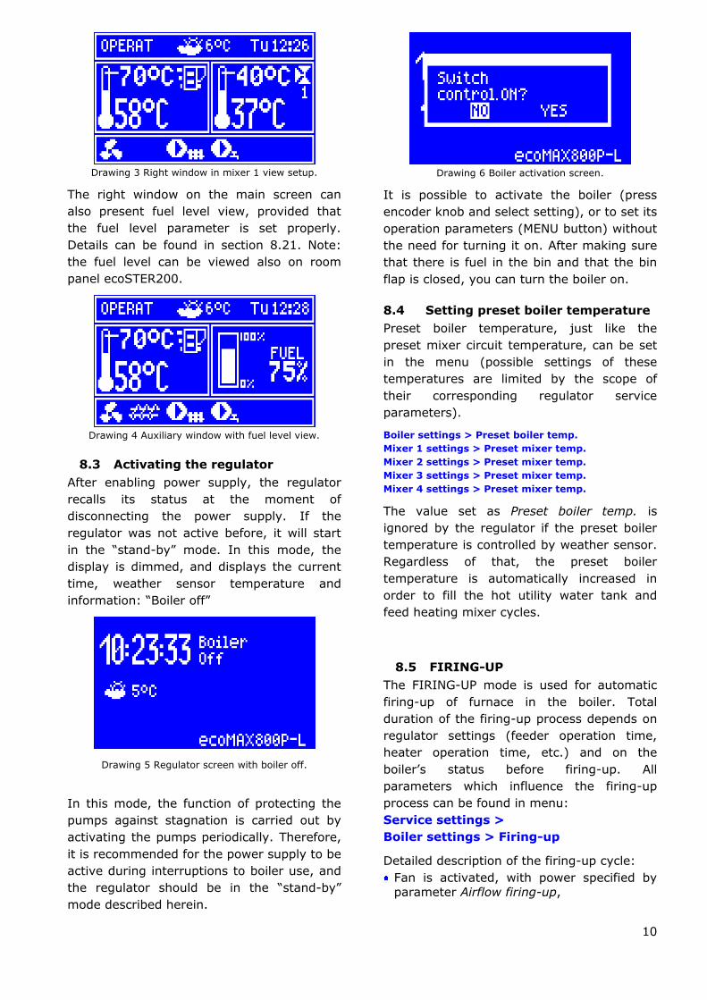
Drawing 3 Right window in mixer 1 view setup.
The right window on the main screen can
also present fuel level view, provided that
the fuel level parameter is set properly.
Details can be found in section 8.21. Note:
the fuel level can be viewed also on room
panel ecoSTER200.
Drawing 4 Auxiliary window with fuel level view.
8.3 Activating the regulator
After enabling power supply, the regulator
recalls its status at the moment of
disconnecting the power supply. If the
regulator was not active before, it will start
in the ―stand-by‖ mode. In this mode, the
display is dimmed, and displays the current
time, weather sensor temperature and
information: ―Boiler off‖
Drawing 5 Regulator screen with boiler off.
In this mode, the function of protecting the
pumps against stagnation is carried out by
activating the pumps periodically. Therefore,
it is recommended for the power supply to be
active during interruptions to boiler use, and
the regulator should be in the ―stand-by‖
mode described herein.
Drawing 6 Boiler activation screen.
It is possible to activate the boiler (press
encoder knob and select setting), or to set its
operation parameters (MENU button) without
the need for turning it on. After making sure
that there is fuel in the bin and that the bin
flap is closed, you can turn the boiler on.
8.4 Setting preset boiler temperature
Preset boiler temperature, just like the
preset mixer circuit temperature, can be set
in the menu (possible settings of these
temperatures are limited by the scope of
their corresponding regulator service
parameters).
Boiler settings > Preset boiler temp.
Mixer 1 settings > Preset mixer temp.
Mixer 2 settings > Preset mixer temp.
Mixer 3 settings > Preset mixer temp.
Mixer 4 settings > Preset mixer temp.
The value set as Preset boiler temp. is
ignored by the regulator if the preset boiler
temperature is controlled by weather sensor.
Regardless of that, the preset boiler
temperature is automatically increased in
order to fill the hot utility water tank and
feed heating mixer cycles.
8.5 FIRING-UP
The FIRING-UP mode is used for automatic
firing-up of furnace in the boiler. Total
duration of the firing-up process depends on
regulator settings (feeder operation time,
heater operation time, etc.) and on the
boiler‘s status before firing-up. All
parameters which influence the firing-up
process can be found in menu:
Service settings >
Boiler settings > Firing-up
Detailed description of the firing-up cycle:
Fan is activated, with power specified by parameter Airflow firing-up,

11
Small dose of fuel - 20% of the main dose - is supplied,
Furnace status is checked – i.e. if within the time specified by parameter Ignition
test time from the time of activating the fan, the exhaust temperature reaches the
value Ex.temp.for fired-up or increases by Ex.temp.delta, the firing-up process will
end. This means, that firing-up has been successful and the regulator switches into
the OPERATION mode. If the firing-up
criteria are not met, the regulator will attempt to clean and fire-up the furnace:
Poker is activated for Poker cycle time, Fuel is supplied for Feeding time,
Fan is activated with power Airflow firing-up
Lighter is activated for Firing-up time. Within that time, the regulator checks
whether the fuel in the furnace has flamed
up. A condition of firing-up is increase in temperature read by exhaust temperature
sensor by value of Ex.temp.delta or increase in emission temperature
exceeding Ex.temp.for fired-up. If firing-up is successful, the lighter is deactivated and
the regulator goes into OPERATION mode.
If firing-up is unsuccessful, another attempts
to fire the furnace up are made, during which
the fuel dose (feeding time) is reduced to
10% of the first attempt dose.
Drawing 7 Signalling the FIRING-UP mode and number
of current attempt.
After three unsuccessful attempts, an alarm
Failed firing-up attempt is reported. In such
case, the boiler operation is halted. Boiler
operation cannot be continued automatically
- service crew must intervene. After
removing causes of impossibility to fire-up,
the boiler must be restarted.
8.6 OPERATION
In this mode, the regulator operates
automatically, according to STANDARD, or
Individual Fuzzy Logic algorithm.
Drawing 8 Main window view during operation.
The fan operates continuously, which is
presented in Drawing 9. Fuel feeder is
activated cyclically. A cycle consists of feeder
operation time and duration of feeding
interval. Fan power and feeder operation
cycle are determined by one of the following
control algorithms.
Drawing 9 Fan and feeder operation cycles
If, in the OPERATION mode, it becomes
necessary to fill the HUW tank at preset
boiler temperature lower than temperature
required to fill the tank, the regulator will
automatically increase the preset boiler
temperature for the time of filling the HUW
tank.
8.7 OPERATION in the I.FuzzyLogic
mode
This mode can be activated in the menu:
Regulation mode
The Individual Fuzzy Logic function, the
parameters of which are selected individually
to the given boiler, allows to obtain optimal
combustion process, which favours
environmental protection, savings of
consumed fuel and in most cases releases
the user from the necessity of adjusting
regulator parameters.
During operation with Individual Fuzzy Logic
algorithm, there is no need to set up the
feeder operation parameters (feeding times,
feeding intervals), and airflow power for the
each boiler output level. 3-phase modulation
is inactive - the regulator automatically and

12
smoothly selects parameters for feeder and
fan control.
In the Individual Fuzzy Logic mode, the
regulator strives to avoid switching the boiler
into the SUPERVISION mode, and to supply
as much heat, as the CH system requires at
the time. Switching into SUPERVISION is
made only after exceeding the preset boiler
temperature by 5°C.
One should bear in mind that the Individual
Fuzzy Logic algorithm is selected individually
to the given boiler and fuel type, and it can
operate properly only with the specific fuel
and boiler. For this reason, the Individual
Fuzzy Logic mode must be activated by
boiler manufacturer, in accordance with point
23.1. If this mode is not activated, attempt
to change the mode will trigger message
‗Function unavailable‘.
Modifying parameters of the
Individual Fuzzy Logic algorithm.
In some cases, depending on fuel quality, it
may be necessary to fine-tune the airflow in
the Individual Fuzzy Logic mode. The user
can change:
Boiler settings > Output modulation >
Blow-in out. correct. FL
Boiler settings > Output modulation >
Min. boiler output in FL
Boiler settings > Power modulation >
Max. boiler output in FL
The scope of settings adjustments is
intentionally limited. It is not
recommended to change the Airflow
correction FL parameter if the
combustion is proper, i.e. there are no
underburnt fuel particles. If the fuel is of
poor quality and there are underburnt
particles, the provided amount of air can be
increased. If the fuel is very dry, causing it
to burn fast, and the furnace burns out too
intensively, the value of FL airflow correction
can be decreased.
When adjusting the Individual
Fuzzy Logic, values of parameters
concerning: airflow power, feeder
operation and feeder intervals
which can be found in the Boiler
settings > Output modulation
menu are not used in the regulator
control algorithm. These settings
are used only in STANDARD mode.
When using the Individual Fuzzy
Logic control, the fan intake
aperture should be open to the
maximum and the boiler should be
clean. Shall it be necessary to
replace the fan or the feeder, use
identical types thereof.
After exceeding the preset boiler
temperature by 5 degrees, the regulator
automatically switches into the
SUPERVISION mode.
8.8 Operation in the Standard mode
The ecoMAX800P1-L boiler regulator is
equipped with boiler output modulation
mechanism, which allows to change its
output gradually, as the boiler temperature
approaches the preset value. In this mode,
the controller uses an output modulation
algorithm.
The currently selected output level - one of
three available - is presented on the display
in the form of a three-bar indicator on the
left side of the boiler icon.
Drawing 10 Output level indicator in the main window.
Parameters for all output levels are available
in the menu:
Boiler settings > Output modulation
Each of the levels - referred to as 100%,
50% and 30% respectively - can be
attributed with different fuel feeding time
and airflow power, which translates into

13
actual boiler output level. When the boiler is
supposed to operate at specific output level
is determined by values called hysteresis, H1
and H2 respectively. Each of these values
relates to measured boiler temperature
relative to its preset value. The H1 and H2
values can be set in such a way that
modulation will take place without
intermediate stage, i.e. shift from 100% to
30%.
Drawing 11 Output modulation hystereses H1 and H2.
If the boiler temperature reaches the preset
value, the regulator will switch into
SUPERVISION mode.
8.9 SUPERVISION
The SUPERVISION mode occurs both during
operation with STANDARD, as well as with
Individual Fuzzy Logic control algorithm.
The regulator switches into the
SUPERVISION automatically, without the
user‘s intervention:
- in the case of Standard control mode -
upon reaching preset boiler temperature,
- during Individual Fuzzy Logic control - upon
exceeding the preset boiler temperature by
5°C. In the Individual Fuzzy Logic mode, the
regulator strives to avoid switching the boiler
into the SUPERVISION mode, and to supply
as much heat, as the CH system requires at
the time.
In the SUPERVISION mode, the regulator
supervises the furnace, so that it would not
go out. For this purpose, the airflow and the
feeder are activated only for a while, rarer
than in the OPERATION mode. Without
causing further temperature increase.
The airflow does not work continuously,
it is activated cyclically together with
the fuel feeder, which prevents the
flame from going out during boiler
standstill.
Drawing 12 View of main window in the SUPERVISION
mode.
All parameters regarding boiler setup in the
SUPERVISION can be found in the menu:
Service settings > Boiler settings >
Supervision
Parameters of the SUPERVISION mode
should be set in accordance with boiler
manufacturer‘s recommendations. They
should be chosen in such a way, that the
furnace did not go out during boiler standstill
(at the same time, it should not fire up too
intensively, as this will trigger increase in the
boiler temperature). Duration of the feeder
operation and interval in the SUPERVISION
mode are set using parameters:
... > Supervision > Supervision feeding
time
... > Supervision > Supervision feeder
interval
The time of extending the airflow in order to
ignite fuel after feeding thereof is set in:
... > Supervision >Airflow operation
extend.
Parameters should be selected in
such a way, that boiler
temperature would gradually
decrease when this mode is active.
Improper settings can cause the
boiler to overheat.
Airflow in the SUPERVISION mode
operates with power set in the power
modulation parameter 30% Airflow
power.
The regulator returns to the OPERATION
mode automatically after boiler temperature

14
decreases by the value of boiler hysteresis in
relation to the preset temperature.
Maximum boiler operation time in the
supervision mode is defined by parameter:
... > Supervision > Supervision time
If after lapse of this time from the moment
of the regulator‘s entering the supervision
mode, there is no need to reactivate the
boiler, the regulator will commence the
process of putting the boiler out.
8.10 PUTTING OUT
In the PUTTING OUT mode, remains of the
pellet are burnt out and the boiler is
prepared for standstill or deactivation.
All parameters which influence the process of
putting out can be found in menu:
Service settings >
Boiler settings > Putting out
Detailed description of the putting out cycle:
Feeder operation is halted, Fuel remains are burnt out - Fan is
activated for Putting out time and with power specified by parameter Putting out
airflow,
The furnace is cleared - the poker is activated.
After automatic putting out, the regulator
switches into STANDSTILL mode.
8.11 STANDSTILL
In the STANDSTILL mode, the boiler is put
out and awaits signal to resume heating.
A signal to start heating can be:
decrease in preset boiler temperature below the preset temperature minus the
value of boiler hysteresis (Boiler hysteresis),
if the boiler is set to work with a buffer - decrease in upper buffer temperature
below the preset value (Loading start
temperature).
8.12 Hot utility water settings HUW
The device controls temperature of the hot
utility water - HUW – tank, provided that a
HUW temperature sensor is connected. If the
sensor is disconnected, an information about
lack thereof is displayed in the main window.
The parameter:
HUW settings > HUW operation mode
allows the user to:
disable filling of the tank, parameter
off,
set HUW priority, using the priority
parameter - in this case, the CH pump
is deactivated to speed up filling of
the HUW tank.
set simultaneous operation of the CH
and HUW pump, using parameter no
priority,
enable the summer function.
8.13 Setting preset HUW temperature
Preset HUW temperature is defined by
parameter:
HUW settings > HUW preset temp.
8.14 HUW tank hysteresis
Below temperature HUW preset temp.
reduced by HUW tank hysteresis, the HUW
pump is activated in order to fill the HUW
tank.
When value of hysteresis is set too
low, the HUW pump will start faster
after decrease in HUW temperature.
8.15 Enabling the SUMMER function
In order to activate the SUMMER function,
which enables to load the HUW tank in the
summer, without the need for activating the
CH system and mixer cycles, set the
parameter HUW pump operation mode to
summer.
The SUMMER function cannot be
enabled if the HUW sensor is
disconnected.
Do not enable the summer
function if the HUW pump is
disconnected or damaged.
The SUMMER function can be enabled
automatically, on the basis of readouts from
the weather sensor. This functionality is
enabled with the following parameters:
HUW settings > Auto detect. SUMMER
HUW settings > Activ.temp.SUMMER
HUW settings > Deactiv.temp.SUMMER

15
8.16 HUW tank disinfection
The regulator has a function of automatic,
periodic heating of the HUW tank to
temperature of 70 °C. The purpose is to
remove bacterial flora from the HUW tank.
The household members must
definitely be informed about the fact
of activating disinfection, as there is
a hazard of scalding with hot utility
water.
Once a week on Sunday night, at 02:00, the
regulator increases the HUW tank
temperature. After 10 minutes of keeping the
tank at 70 °C, the HUW pump is deactivated
and the boiler resumes normal operation. Do
not enable the disinfection function if HUW
support is deactivated.
8.17 Mixer circuits settings
Settings for the first mixer circuit can be
found in the menu:
Mixer 1 settings
Settings for other mixers can be accessed in
next menu items and they are identical for
each circuit.
Settings for mixer without weather sensor
It is necessary to manually set the required
water temperature in the heating mixer
circuit using parameter Preset mixer temp.,
e.g. at a value of 50°C. The value should
allow to obtain the required room
temperature.
After connecting room thermostat, it is
necessary to set a value of decrease in
preset mixer temperature by thermostat
(parameters Mixer room therm.) e.g. at 5°C.
This value should be selected by trial and
error. The room thermostat can be a
traditional thermostat (no/nc), or room panel
ecoSTER200. Upon activation of the
thermostat, the preset mixer circuit
temperature will be decreased, which, if
proper decrease value is selected, will stop
growth of temperature in the heated room.
Settings for mixer with weather sensor
(without room thermostat ecoSTER200)
Set parameter Weather contr.mixer to on.
Select weather curve as per point 8.18
Using parameter Curve translation, set
preset room temperature following the
formula:
Preset room temperature = 20°C + heating
curve translation.
Example.
To obtain room temperature of 25°C, value
of the heating curve translation must be set
at 5°C. To obtain room temperature of 18°C,
value of the heating curve translation must
be set at -2°C.
In this setup, it is possible to connect a room
thermostat which will equalize the inaccuracy
of selecting heating curve, if the selected
heating curve value is too high. In such case,
it is necessary to set the value of preset
mixer temperature decrease by thermostat,
e.g. at 2°C. After opening of the thermostat
contacts, the preset mixer circuit
temperature will be decreased, which, if
proper decrease value is selected, will stop
growth of temperature in the heated room.
Settings for mixer with weather sensor and
with room thermostat ecoSTER200)
Set parameter Weather contr.mixer to on.
Select weather curve as per point 8.18
The ecoSTER200 regulator automatically
translates the heating curve, depending on
the preset room temperature. The regulator
relates the setting to 20 °C, e.g. for preset
room temperature = 22 °C, the regulator will
translate the heating curve by 2°C, for
preset room temperature = 18 °C, the
regulator will translate the heating curve by
-2 °C. In some cases described in point 8.18,
it may be necessary to fine-tune the heating
curve translation.
In this setup, the ecoSTER200 room
thermostat can:
- decrease the heating cycle temperature by
a constant value when the preset room
temperature is reached. Analogously, as
specified in the previous point (not
recommended), or
- automatically, continuously correct the
heating cycle temperature.
It is not recommended to use both
options at the same time.

16
Automatic correction of room temperature is
carried out in accordance with the following
formula:
Correction = (Preset room temperature -
measured room temperature) x room
temperature coefficient /10
Example.
Preset temperature in the heated room (set
at ecoSTER200) = 22 °C. Temperature
measured in the room (by ecoSTER200) =
20 °C. Room temp. coeff. = 15.
Preset mixer temperature will be increased
by (22 °C - 20 °C) x 15/10 = 3 °C.
It is necessary to find appropriate value of
the Room temp. coeff. Range: 0…50. The
higher the coefficient, the greater the
correction of preset boiler temperature. If
the setting is ―0‖, the preset mixer
temperature is not corrected. Note: setting
a value of the room temperature coefficient
too high may cause cyclical fluctuations of
the room temperature!
8.18 Weather controlled operation
Depending on the temperature measured
outside the building, both preset boiler
temperature and temperatures of mixer
circuits can be controlled automatically. If
proper heating curve is selected, the
temperature of the circuits is calculated
automatically, depending on the outdoor
temperature. Thus, if the selected heating
curve is appropriate for the given building,
the room temperature stays more or less the
same, regardless of the temperature outside.
Note: during trial and error selection of
appropriate heating curve, it is necessary to
exclude influence of the room thermostat on
regulator operation (regardless of whether
the room thermostat is connected or not), by
setting the parameter:
Mixer 1 settings > Mixer room therm. to
―0‖.
If a room panel ecoSTER200 is connected, it
is also necessary to set the parameter Room
temp. coeff. to ―0‖.
Guidelines for proper setting
of the heating curve:
- floor heating 0,2 -0,6
- radiator heating 1,0 - 1,6
- boiler 1,8 - 4
Drawing 13 Heating curves.
Guidelines for selection of appropriate
heating curve:
- if the outdoor temperature drops, and the
room temperature increases, the selected
heating curve value is too high,
- if the outdoor temperature drops, and the
room temperature drops as well, the selected
heating curve value is too low,
- if during frosty weather the room
temperature is proper, but when it gets
warmer - it is too low, it is recommended to
increase the Curve translation and to select a
lower heating curve,
- if during frosty weather the room
temperature is too low, and when it gets
warmer - it is too high, it is recommended to
decrease the Curve translation and to select
a higher heating curve.
Buildings with poor thermal insulation require
higher heating curves, whereas for buildings
which have good thermal insulation, the
heating curve can have lower value.
The regulator can increase or decrease the
preset temperature, calculated in accordance
with the heating curve, if it exceeds the
temperature range for the given circuit.

17
8.19 Description of settings for night-
time decreases
The regulator allows to set intervals for
decreasing preset temperature of boiler,
heating curves, hot utility water tank, and
operation time of the circulating pump.
The intervals allow to decrees the preset
temperature at specified periods of time –
e.g. at night, or when the users leave the
heated rooms (e.g. when the household
members got to work/school). This allows to
decrease the preset temperature
automatically, without losing thermal comfort
and with decreased fuel consumption.
In order to activate the intervals, set
parameter Night-time decrease for the given
heating circuit to on.
Night-time decreases can be defined
separately for weekdays, Saturdays and
Sundays.
Drawing 14 Interval selection window.
It is necessary to specify beginning and end
of the given interval, as well as the value by
which the preset temperature is to be
decreased. Three intervals per day are
available.
Drawing 15 Editing intervals.
Below is an example of night-time decrease
in preset room temperature, lasting from
22:00 till 06:00, as well as another decrease
between 09:00 and 15:00.
Start defining intervals for the
given day from 00:00
Drawing 16 Example of defining intervals.
In the presented example, the regulator will
decrease the preset boiler temperature by
3 °C between 00:00 and 06:00. Between
06:00 and 09:00, the regulator will be
retaining the regular preset boiler
temperature (no decrease). From 09:00 till
15:00, the regulator will keep the preset
boiler temperature decreased by 5 °C.
Between 15:00 and 22:00, the regulator will
be retaining the regular preset boiler
temperature (no decrease). From 22:00 till
23:59, the regulator will keep the preset
boiler temperature decreased by 3 °C.
An interval is ignored if the decrease
value is set to ―0‖, even if its range
of hours was specified.
Decrease in the boiler preset
temperature by interval is signalled
with a letter ―S‖ in the main display
window.
Drawing 17 Signalling active scheduled reduction.
8.20 Circulating pump control
Note: the circulating pump functionality is
available only if an additional extension
mixer module is attached to the
ecoMAX800P1-L regulator.
The settings can be found in:

18
Night-time decrease > Circ. pump
and
Service settings>(Password)>CH &
HUW settings
Setting for temporal control of the circulating
pump are the same as for night-time
decreases. At specified intervals, the
circulating pump is off. Otherwise, the
circulating pump is activated for circ. pump
operation time every circ. pump standstill
time. Detailed settings can be found in point
15.7.
8.21 Fuel level setup
Activating the fuel level gauge
In order to enable display of the fuel level,
set value of parameter
Fuel level > Alarm level
to a value greater than zero, e.g. 10%
Rotate the TOUCH and PLAY knob in the
main window to open the fuel level window.
Tip: the fuel level can be viewed in the room
panel ecoSTER200. The room panel is not
standard equipment of the regulator.
Drawing 18 Auxiliary window with fuel level gauge view.
Using the fuel level gauge
Every time after filling the fuel bin to the
required level, press and hold the knob while
in the main window to open the prompt:
Drawing 19 fuel level service.
Select and confirm ―YES‖ to set the fuel level
to 100%.
Caution: The fuel can be replenished at any
time, i.e. you do not have to wait until the
fuel bin becomes empty. Nonetheless, the
fuel should always be replenished to the level
equal 100% and conform by press-holding
the knob.
Description of operation
The regulator calculates the fuel level basing
on the current fuel consumption. Default
settings do not always correspond to the
actual consumption of fuel by the given
boiler, therefore, for proper operation this
method requires the regulator user to
perform level calibration. No additional fuel
level sensors are required.
Calibration
Fill in the fuel bin to the level corresponding
to full load, and set the parameter:
Fuel level >Fuel level calibration > Fuel
level 100%
The indicator in the main window will be set
to 100%. On-going calibration process is
signalled by flashing fuel level gauge. The
gauge will flash until the time of marking the
point corresponding to minimal fuel level.
One must systematically control the
decreasing level of fuel in the bin. When the
level reaches the requested minimum, set
the value of the parameter:
Fuel level >Fuel level calibration > Fuel
level 0%
8.22 Cooperation with secondary feeder
The regulator can cooperate with a fuel batch
sensor, which is an element of the boiler
equipment.
On the basis of secondary feeder operation
schedule, specified in the menu:
Extra feeder schedule
and signals from fuel level sensor, the
regulator controls fuel replenishment in the
boiler bunker.
At the moment of activation specified by the
scheduled interval, the secondary feeder
starts operation in accordance with
algorithms, specified by parameters referred
to in point 14.18. During operation of
secondary feeder, signal from bunker batch
sensor is used.

19
8.23 Poker automatics service
The regulator supports poker automatics,
which allows to improve conditions of
burning fuel of worse quality, and to clean
ash from the furnace.
The poker cleans the furnace in FIRING-UP
and PUTTING OUT modes.
If the boiler remains in OPERATION and
SUPERVISION mode for an extended period,
it is possible to clean the boiler
automatically, using parameter:
Boiler settings > Burner cleaning
Point 14.17 describes service parameters for
the poker.
8.24 Information
The information menu allows to view
measured temperatures and to check which
devices are currently active.
You can switch between screens turning the
TOUCH and PLAY knob
After connecting a mixer extension
module, windows with information
about secondary mixers are
activated.
Sign ―CAL‖ in the information
window at valve opening value
indicates that its calibration is
active. Please wait until valve servo
calibration is completed to see its
current status.
8.25 Manual control
The regulator enables manual activation of
executive devices, such as pumps, feeder
motor or blower. This allows to check
whether the given devices are operational
and properly connected. The manual control
menu can only be entered in the STOP mode,
i.e. when the boiler is deactivated.
Drawing 20 View of manual control window, where OFF
means that the device is off, and ON - that it is on.
Note: prolonged activity of fan,
feeder or other executive device
can cause a hazard.
8.26 Restoring user settings
It is possible to restore default parameter of
settings which are available in the main
menu.
Drawing 21 Restoring user settings.
Note: service parameters will not be
restored.


REGULATOR INSTALLATION AND SERVICE SETTINGS MANUAL
ecoMAX 800, model P1-L
22
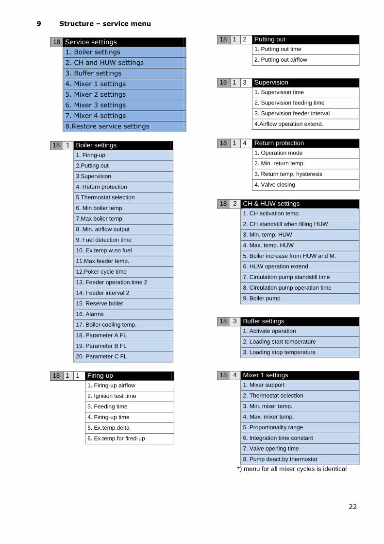
9 Structure – service menu
18 Service settings
1. Boiler settings
2. CH and HUW settings
3. Buffer settings
4. Mixer 1 settings
5. Mixer 2 settings
6. Mixer 3 settings
7. Mixer 4 settings
8.Restore service settings
18 1 Boiler settings
1. Firing-up
2.Putting out
3.Supervision
4. Return protection
5.Thermostat selection
6. Min boiler temp.
7.Max boiler temp.
8. Min. airflow output
9. Fuel detection time
10. Ex.temp.w.no fuel
11.Max.feeder temp.
12.Poker cycle time
13. Feeder operation time 2
14. Feeder interval 2
15. Reserve boiler
16. Alarms
17. Boiler cooling temp.
18. Parameter A FL
19. Parameter B FL
20. Parameter C FL
18 1 1 Firing-up
1. Firing-up airflow
2. Ignition test time
3. Feeding time
4. Firing-up time
5. Ex.temp.delta
6. Ex.temp.for fired-up
18 1 2 Putting out
1. Putting out time
2. Putting out airflow
18 1 3 Supervision
1. Supervision time
2. Supervision feeding time
3. Supervision feeder interval
4.Airflow operation extend.
18 1 4 Return protection
1. Operation mode
2. Min. return temp.
3. Return temp. hysteresis
4. Valve closing
18 2 CH & HUW settings
1. CH activation temp.
2. CH standstill when filling HUW
3. Min. temp. HUW
4. Max. temp. HUW
5. Boiler increase from HUW and M.
6. HUW operation extend.
7. Circulation pump standstill time
8. Circulation pump operation time
9. Boiler pump
18 3 Buffer settings
1. Activate operation
2. Loading start temperature
3. Loading stop temperature
18 4 Mixer 1 settings
1. Mixer support
2. Thermostat selection
3. Min. mixer temp.
4. Max. mixer temp.
5. Proportionality range
6. Integration time constant
7. Valve opening time
8. Pump deact.by thermostat
*) menu for all mixer cycles is identical

23
10 Hydraulic diagrams
10.1 Schema 1
Drawing 22 Diagram with four-way valve controlling the central heating cycle2, where: 1 – boiler with
feeder, 2 – ecoMAX800P1-L regulator, 3 – regulator control panel, 4 – boiler temperature sensor, 5 – return
temperature sensor, 6 -temperature sensor—weather, 7 – room thermostat, 8 –mixer servo, 9 -
temperature sensor – mixer, 10 –mixer pump, 11 – domestic hot water temperature sensor,
12 – domestic hot water pump, 13 – domestic hot water tank.
In order to improve water circulation in the boiler gravity circulation circuit
(marked as bold in the drawing), do as follows: use large nominal sections DN of
the pipe and the four-way valve, avoid numerous elbows and narrowings of the
section, apply other rules regarding structure of gravity systems, such as
observing drops, etc.
If the return sensor is clip-on, insulate it thermally from the surroundings and
improve thermal contact with the pipe by using thermal grease. The boiler pre-
set temperature must be high enough to provide thermal power for the mixer
circuit, while heating the water which returns to the boiler.
SUGGESTED SETTINGS:
Parameter Setting MENU
Return protection on service settings -> boiler settings
Min. return temp. 42 C service settings -> boiler settings
Return temp. hysteresis 2 C service settings -> boiler settings
Valve closing 0% service settings -> boiler settings
Increasing pre-set boiler temp. 5-20 C service settings -> CH and HUW settings
Min. pre-set boiler temperature 65 C service settings -> boiler settings
Mixer support 1 CH on service settings -> mixer 1 settings
Max. preset mixer temp. 75 service settings -> mixer 1 settings
Mixer heating curve 0.8 – 1.4 service settings -> mixer 1 settings
Out. temp. control on service settings -> boiler settings
2The presented hydraulic diagram does not replace the central heating system design and is
provided solely for the purposes of demonstration!

24
Brief description: The DHW pump (12) can start its operation only after the boiler exceeds the CH
activation temp. (by default 40 OC) Mixer pump (10) and servo (8) start operation regardless of
the value of the parameter CH activation temp. The mixer servo (8) founds such valve opening
stage at which the temperature at sensor (9) will be equal to the preset mixer temperature 1.
When the temperature on sensor (5) drops below the value Min. return temp., the servo (8),
closes to the value close valve for return protect. After the temperature on sensor (5)increased
buy the value Return temp. hyst., the servo switches into stabilization of preset mixer
temperature 1. The setting Mixer 1 operation = CH on guarantees that even in the case of the
boiler (1) overheating, the mixer (8) will open maximally, and the mixer pump (10) will not be
disabled at the moment of exceeding the Max.mixer temp. Return protection is available only for
mixer 1 circuit.
10.2 Schema 2
Drawing 23 Diagram with thermostatic three-way valve which protects the temperature of return
water3, where:1 – boiler with feeder, 2 – ecoMAX800P1-L regulator, 3 – regulator control panel, 4 –boiler
temperature sensor, 5 – return temperature sensor, 6 – central heating cycle pump, 7 – thermostatic three-
way valve, 8 –throttle (poppet) valve, 9 – room thermostate, 10 – temperature sensor-weather, 11 –
domestic hot water tank, 12 – domestic hot water pump, 13 – domestic hot water temperature sensor.
SUGGESTED SETTINGS:
Parameter Setting MENU
Return protection off service settings -> boiler settings
Mixer operation 1 off service settings -> mixer 1 settings
Brief description: The CH pump (6), and the DHW pump (12) can start their operation only after
the boiler exceeds the CH activation temp. (by default 40 C). The thermostatic valve (7) closes at
the initial stages of heating, when the water getting into the boiler is cold. This causes the boiler
water to flow in a short cycle: boiler (1) – throttle valve (8) - thermostatic valve (7) – pump (6).
The thermostatic valve (7) opens after the temperature returning to the boiler increases,
3The presented hydraulic diagram does not replace the central heating system design and is
provided solely for the purposes of demonstration!

25
directing the boiler water to the central heating system. When the temperature measured by
sensor (13) drops below the preset DHW temperature, the DHW pump (12) is enabled. The DHW
pump (12) will be disabled after the DHW tank (11) is filled, i.e. when the temperature on sensor
(13) is equal to the preset DHW temperature.
10.3 Schema 3
Drawing 24 Diagram with thermostatic three-way valve which protects return water temperature,
and two three-way valves which feed floor heating, as well as with two additional mixer cycles
after connecting an extension module4, where:1 – boiler, 2 – ecoMAX800P1-L regulator, 3 – control
panel, 4 – boiler temperature sensor, 5 – return temperature sensor, 6- central heating cycle pump, 7 –
thermostatic three-way valve (protecting boiler return), 8 – circulating pump, 9 –temperature sensor-
weather, 10 – fluid coupling (eliminates necessity of balancing the pumps‘ flows), 11 – domestic hot water
temperature sensor, 12 – domestic hot water pump, 13 – mixer servo 1, 14 – mixer pump 1, 15 – external
thermostat protecting floor heating 55 ºC (it cuts off electricity supply for mixer pump after exceeding
maximum temperature - the thermostat is not included in the regulator), 16 –room thermostat of mixer 1,
17 – mixer temperature sensor 1,18 –mixer servo 2, 19 – mixer pump 2, 20 – external thermostat
protecting floor heating 55 ºC, 21 – mixer room thermostat 2, 22 – mixer temperature sensor 2,23 – mixer
servo 3, 24 – mixer pump 3, 25 – external thermostat protecting floor heating 55 ºC, 26– room thermostat
of mixer 3, 27 – mixer temperature sensor 3,28 –mixer servo 4, 29 – mixer pump 4, 30 – room thermostat
of mixer 4, 31 – mixer temperature sensor 4, 32 – extension mixer module, 33 – domestic hot water tank.
4The presented hydraulic diagram does not replace the central heating system design and is
provided solely for the purposes of demonstration!
OPTION – available after connecting
additional extension module

26
SUGGESTED SETTINGS:
Parameter Setting MENU
Return protection off service settings -> boiler settings
Mixer support 1 on, floor service settings -> mixer 1 settings
Max. pre-set mixer temp. 1 50 C service settings -> mixer 1 settings
Mixer weather control 1, 2, 3, 4 on menu mixer settings 1,2,3,4
Mixer heating curve 1 0.2 – 0.6 service settings -> mixer 1 settings
Mixer support 2 on, floor service settings -> mixer 2 settings
Max. pre-set mixer temp. 2 50 C service settings -> mixer 2 settings
Mixer heating curve 2 0.2 – 0.6 service settings -> mixer 2 settings
Mixer support 3 on, floor service settings -> mixer 3 settings
Max. pre-set mixer temp. 3 50 C service settings -> mixer 3 settings
Mixer heating curve 3 0.2 – 0.6 service settings -> mixer 3 settings
Mixer support 4 CH on service settings -> mixer 4 settings
Max. pre-set mixer temp. 4 80 C service settings -> mixer 4 settings
Mixer heating curve 4 0.8 – 1.4 service settings -> mixer 4 settings
Boiler weather control off service settings -> boiler settings

27
11 Technical data
Voltage 230V~; 50Hz;
Current consumed by regulator
I = 0,04 A5
Maximum rated current 6 (6) A
Regulator protection rating IP20, IP006
Ambient temperature 0...50 C
Storage temperature 0...65 C
Relative humidity
5 - 85% without
vapour
condensation
Measuring range of temperature
sensors CT4 0...100 C
Measuring range of temperature
sensors CT4-P -35...40 C
Accuracy of temperature
measurements with sensors CT4
and CT4-P
2 C
Temperature measure range for
CT2S sensors 0..380 C
Terminals
Screw terminal on
the mains voltage
side 2,5mm2
Screw terminals on
the control side
1,5mm2
Display Graphic 128x64
External dimensions
Control panel:
164x90x40 mm
Executive module:
140x90x65 mm
Total weight 1,0 kg
Norms PN-EN 60730-2-9
PN-EN 60730-1
Software class A
Protection class To be built into
class I devices
Basic set includes:
- boiler temperature sensor
- feeder temperature sensor
- DHW temperature sensor
- return temperature sensor
1 piece
1 piece
1 piece
1 piece
5 This is the current consumed by the regulator (after
connecting 2 executive modules and panel). Total
electricity consumption depends on devices connected to
the regulator. 6 IP20 – from the front side of the executive module,
IP00 – from the side of terminals of the executive
module, detailed information presented in point 13.5.
- emission temperature sensor
- executive module
- control panel
- module-module lead
- module-panel lead
1 piece
2 pcs.
1 piece
1 piece
1 piece
- panel cover
- panel plugs
- panel screws B3x8
- manual
- warranty
1 piece
4 pcs.
2 pcs.
1 piece
1 piece
12 Conditions of storage and
transport
The regulator cannot be exposed to direct
effects of weather, i.e. rain and sunlight.
Storage and transport temperature cannot
exceed the range of -15…65 °C.
During transport, the device cannot be
exposed to vibrations greater than those
typical of normal road transport.
13 REGULATOR INSTALLATION
13.1 Environmental conditions
On account of risk of shock, the regulator
has been designed to be used in an
environment in which dry conductive
pollutants occur (pollution level 3, acc. to
PN-EN 60730-1).
Due to the risk of fire, it is prohibited to
operate the regulator in explosive gas and
flammable dust atmosphere (e.g. coal dust).
The regulator should be separated using
appropriate enclosure.
Moreover, the regulator cannot be used in
the presence of vapour condensation, and be
exposed to water.
13.2 Installation requirements
The regulator should be installed by a
qualified and authorised fitter, in accordance
with the applicable norms and regulations.
The manufacturer bears no responsibility for
damages caused by failure to observe this
manual.
The regulator is to be built-in. The regulator
cannot be used as a stand-alone device.
The temperature of the ambient and the
fitting surface cannot exceed the range of 0 -
50˚C. In the basic version, the device
consists of three modules, including control
panel and two executive modules. All parts
are electrically interconnected.

28
13.3 Installation of control panel
The control panel is to be enclosed on a
mounting plate. Proper thermal insulation
between hot boiler walls and the panel and
the connecting tape must be provided. The
space required for the control panel is shown
in Drawing 27. During installation, follow the
guidelines below.
STEP 1
A hole must be made in the mounting plate,
in accordance with the drawing below.
Drawing 25 Fitting the regulator in a mounting plate,
where: 1 – control panel, 2 – sheet metal screw 2.9x13,
3 – hole plug.
STEP 2
Remove the lid (5), plug the cable (6) and
put the lid (5) back on, securing it with
screws (4). The cable should be lead out
through the round groove in the enclosure.
Drawing 26 Connecting lead to the panel, where: 4-
B3x6 screw for thermoplastic materials, 5 – lid, 6 – lead
connecting the control panel with the executive panel.
Maximum length of the lead (6) is
5m with gauge of 0,5mm2
STEP 3
Screw the panel to the mounting plate using
sheet metal screws, insert the hole plugs.
Drawing 27 Conditions of enclosing the panel, where 1 –
panel, 2 –ventilation holes for air circulation (note: the
holes cannot decrease the required IP protection rate;
ventilation holes are not required if the limiting
temperature of the panel surroundings is not exceeded;
the ventilation holes do not always guarantee that the
temperature of the panel surroundings will be lowered,
in such case use other methods).
13.4 Executive module installation
The casing must meet protection rate
appropriate for the environmental conditions
in which the regulator will be used.
Moreover, it must prevent the user from
accessing hazardous, live parts, e.g.
terminals. Enclosing can be done using
standard casing. In such case, the user can
only access front surface of the executive
module. Enclosing can also be made using
elements of boiler which surround the entire
module Drawing 30b. Space required for a
single module is presented in Drawing 29
and Drawing 30.
The executive module is designed to be fitted
on a standardised bus bar DIN TS35. The bus
should be securely fixed to a rigid surface.
Before placing the module on the bus (1) lift
the taps (2) using a screwdriver, Drawing 28.
After placing the module on the bus, push
the taps (2) into their original position. Make
sure that the device is tightly fixed and it
cannot be removed from the bus without
using a tool.

29
Drawing 28 Mounting regulator on bus, where:
1 – bus DIN TS35, 2 – taps.
Due to safety requirements, a safe distance
between active parts of the executive module
terminals and the conductive (metal)
elements of the enclosure must be kept (at
least 10 mm).
Connecting wires must be protected against
being torn out, loosened, or they must be
enclosed in a way which prevents any
tensions in relation to the wires.
Drawing 29 Conditions for enclosing the module.
Drawing 30 Methods of enclosing the module: a – in
modular enclosure with access to front surface, b – in
enclosure without access to the front of the enclosure.
13.5 IP protection rate
Enclosure of the regulator‘s executive
module provides various IP protection rates,
depending on the method of installation.
Drawing 30a provides and explanation. After
enclosing in accordance with this drawing,
the device has protection rate IP 20 from the
front side of the executive module enclosure
(specified on the rating plate). From the side
of the terminals, the casing has protection
rate IP00, thus the terminals of the executive
module must unconditionally be enclosed, in
order to prevent access to this part of the
casing.
If it is necessary to access the part with the
terminals, disconnect the mains supply,
make sure that there is no voltage on
terminals and leads, and remove the
executive module enclosure.
13.6 Connecting electrical system
Regulator is designed to be fed with 230V~,
50Hz voltage. The electrical system should
be:
three core (with protective wire),
in accordance with applicable
regulations.
Caution: After the regulator is
turned off using the keyboard,
dangerous voltage can occur on the
terminals. Before starting any
assembly works, you must
disconnect the mains supply and
make sure that there is no
dangerous voltage on the terminals
and the leads.
The connection wires should not have contact
with surfaces of temperature exceeding the
nominal temperature of their operation.
Terminals number 1-15 are intended only for
connecting devices with mains supply
230V~.
Terminals 16-31 are intended for cooperation
with low voltage devices (below 12 V).
Connecting mains supply
230V~ to terminals 16-31 and
to transmission connectors
RS485 will damage the
regulator and creates risk of an
electric shock!
To control
panel

30
Tips of the connected wires, especially power
leads, must be secured against splitting by
means of insulated clamp sleeves, in
accordance with the drawing below:
Drawing 31 Securing wire tips: a) right, b) wrong.
The feeder cable should be connected to the
terminals marked with an arrow.
13.7 Protective connections
The protective conductor of the feeder cable
should be connected to a neutral strip
contacted with the metal casing of the
regulator. The fitting should be connected to
the regulator terminal marked with symbol
and with grounding terminals of the
devices connected to the regulator.

31
Drawing 32 Diagram for electric connections with external devices and sensors.
The regulator must be equipped with a set of pins, inserted in the
connectors for feeding 230V~ devices

32
13.8 Connecting temperature sensors
The regulator cooperates only with CT4i and
CT2S sensors. It is forbidden to use different
sensors.
Sensor leads can be extended with wires
with section of at least 0,5mm2. Total length
of the sensor leads cannot exceed 15 m.
The boiler temperature sensor should be
fitted in the thermometric pipe, situated in
the boiler shell. The feeder temperature
sensor must be fitted on the surface of the
feeder screw pipe. The domestic hot water
temperature sensor - in the thermometric
pipe welded into the tank. It is best to fit the
mixer temperature sensor in a tube (sleeve)
placed in the stream of water flowing in the
pipe, but it is also possible to clip it onto the
pipe, covering the sensor and the pipe with
thermal insulation.
The sensors must be secured
against coming loose from the
measured surfaces.
Good thermal contact between the sensors
and the measured surface must be ensured.
For this purpose, use thermally conductive
paste. Do not pour oil or water over the
sensors.
The sensor cables should be separated from
mains leads. Otherwise, the temperature
indications can be incorrect. Minimum
distance between these leads should be at
least 10 cm.
The sensor leads cannot have contact with
hot elements of the boiler and heating
system. The temperature sensors‘ leads are
resistant to temperature up to 100 °C.
13.9 Connecting weather sensor
The regulator cooperates only with a weather
sensor of the CT4-P type. The sensor should
be installed on the coldest wall of the
building, usually this is the northern wall,
under a roof. The sensor should not be
exposed to direct sunlight and rain. The
sensor should be fitted at least 2 m above
the ground, far from windows, chimneys and
other heat sources which could disturb the
temperature measurement (at least 1,5 m).
Connect the sensor using cable of 0,5 mm2
cross-section, up to 25 m long. Polarity of
the leads is insignificant. Connect the other
end of the cable to the regulator, as shown in
Drawing 32.
Attach the sensor to the wall using tackbolts.
To access the tackbolts holes, unscrew the
sensor lid.
Drawing 33 Connecting weather senor CT4-P.
13.10 Checking temperature
sensors
Temperature sensors CT4/CT4-P/CT2S can
be checked by measuring their resistance at
the given temperature. In the case of finding
significant differences between the value of
measured resistance and the values
presented in the table below, the sensor
must be changed.
The regulator cooperates only with an
exhaust temperature sensor type CT2S. In
order to inspect the sensor, it is necessary to
use a very precise multimeter – otherwise,
the sensor can only be checked roughly.

33
CT4
Temp.
°C Min.
Ω Nom.
Ω Max.
Ω
0 802 815 828
10 874 886 898
20 950 961 972
25 990 1000 1010
30 1029 1040 1051
40 1108 1122 1136
50 1192 1209 1225
60 1278 1299 1319
70 1369 1392 1416
80 1462 1490 1518
90 1559 1591 1623
100 1659 1696 1733
CT4-P
Temp.
°C Min.
Ω Nom.
Ω Max.
Ω
-30 609 624 638
-20 669 684 698
-10 733 747 761
0 802 815 828
10 874 886 898
20 950 961 972
CT2S
Temp.
°C Min.
Ω Nom.
Ω Max.
Ω
0 999,7 1000,0 1000,3
25 1096,9 1097,3 1097,7
50 1193,4 1194,0 1194,6
100 1384,2 1385,0 1385,8
125 1478,5 1479,4 1480,3
150 1572,0 1573,1 1574,2
13.11 Connecting room
thermostat for mixer circuits
Room thermostats connected to executive
module B as per Drawing 32 influences mixer
1 and mixer 2 circuits. If the entire building
heating system is fed by the mixer circuit, all
room thermostat settings for boiler should be
disabled.
After opening of the contacts, the room
thermostat decreases the preset mixer circuit
temperature by the value of preset mixer
temperature decrease from thermostat. This
parameter can be found in:
Mixer 1 settings > Mixer room therm.
The value of this parameter should be
chosen in such a way, that after activation of
room thermostat (opening of contacts), the
temperature in the room decreased.
Other settings as per 8.17
13.12 Connecting reserve boiler
The regulator can control a reserve boiler
(gas- or oil-fired), eliminating the necessity
of enabling or disabling this boiler manually.
The reserve boiler will be enabled if the
temperature of the pellet boiler drops, and
disabled when the pellet boiler reaches an
appropriate temperature. Connection to a
reserve boiler, e.g. oil-fired one, should only
be made by a qualified fitter, in accordance
with the technical documentation of this
boiler.
The reserve boiler should be connected via
relay to terminals 30-31 of regulator
executive module B, as per Drawing 32 and
Drawing 34.
Drawing 34 Model diagram of layout for connecting a
reserve boiler to the ecoMAX800P1-L regulator, where:
1- regulator ecoMAX800P1-L module B 2 – reserve
boiler (gas- or oil-fired), 3 – Module U3, consisting of
relay RM 84-2012-35-1006 and base GZT80 RELPOL.
In a standard version, the regulator is not
equipped with the U3 module. Components
necessary for assembly of the U3 module can
be purchased from the manufacturer of the
ecoMAX800P1-L regulator.
You have to perform assembly
and installation of the module by
yourself, in conformity with the
applicable standards..
To enable control of a reserve boiler, set the
temperature of the CH system at which the
reserve boiler is to be disabled:

34
Drawing 35 Enabling control of a reserve boiler.
Service settings > Boiler settings >
Reserve boiler
Reserve boiler control is deactivated by
setting value of its deactivation temperature
to zero.
When the pellet boiler is fired up, and its
temperature exceeds a preset value, e.g.
25oC, the ecoMAX800P1-L regulator will
disable the reserve boiler (will feed constant
6V to terminals 30-31 of module B). This will
cause release of the U3 module relay coil,
and its contacts will be disconnected. After
the boiler temperature drops below the
parameter auxiliary boiler off temperature,
the regulator ceases to supply voltage to the
terminals 30-31, which will activate the
reserve boiler.
Switching the ecoMAX800P1-L
regulator into OFF mode causes
activation of reserve boiler.
It is recommended to switch the
ecoMAX800P1-L regulator in the OFF mode,
if the pellet boiler gets damaged and there is
a need of operation with reserve boiler. In
the OFF mode, CH system control is inactive
(mixer HUW and boiler pumps, as well as
mixer control - are inactive).
Drawing 36 hydraulic diagram with a reserve
boiler, connection of an open circuit with a closed
one, where: 1 – ecoMAX regulator, 2 – reserve
boiler, 3 – U3 module,
4 –switching valve (with limit switches), 5 – heat
exchanger, recommended setting DHW priority =
off. CH pump = boiler pump = YES.
Drawing 37 Hydraulic diagram with reserve boiler and
four-way valve in closed cycle, where: 1 – ecoMAX
regulator , 2 – reserve boiler, 3 – U3 module, 4 –
switching valve servo (with limit switches).
Note: in order to provide smooth gravitational
water flow in the boiler circuit, collision cross-
section of the switching valve (4) must be greater
than or equal to cross section of the boiler circuit
pipe. Use high cross sections of gravitational
boiler circuit pipes.
Drawing 38 Electric diagram for switching valve of
the reserve boiler, where: 1 – regulator
ecoMAX800P1-L module B, 2 – reserve boiler, 3 –
U3 module, 5 – servo of switching valve (with
limit switches), note: contacts 22, 21, 24 must
have galvanic separation from contacts 12,11,14.

35
13.13 Connecting alarm signalling
The regulator can signal alarm states by
activating a peripheral device, e.g. a buzzer
or a GSM device for sending an SMS - short
messages.
The alarm signalling device should be
connected in accordance with Drawing 39,
via an U3 module, to the ecoMAX800P1-L
regulator, module A.
Drawing 39 Connecting an external alarming device,
where: 1- ecoMAX800P1-L regulator module A, 2 –
external alarming device, 3 – U3 Module.
In order to provide proper operation, set
appropriate value of code for signalling active
alarms in the menu:
Service settings>Boiler settings>Alarms
Selecting a value of ―127‖ will cause
occurrence of voltage between terminals 30-
31 (alarm output activation) if any alarm
occurs. Setting this value to ―0‖ will prevent
the boiler from activating the output in the
case of alarm.
It is also possible to set up the alarm output
in such a way, that it was activated when
one or several selected alarms occur. The
value to which this parameter should be set
for individual alarms is presented in the
following table:
Em
issio
n s
ensor
dam
age
Boiler
overh
eate
d
Exceedin
g feeder
tem
p.
CH
boiler
tem
pera
ture
sensor
dam
age
Feeder
tem
pera
ture
sensor
dam
age
Unsuccessfu
l firing-u
p
att
em
pt
Boiler
unseale
d
AL 1 AL 2 AL 3 AL 4 AL 5 AL6 AL7
1 2 4 8 16 32 64
Example: if you set the value of the
parameter to „8‖, the voltage will be supplied
to the contact only if alarm AL4 occurs.
Setting ―1‖ will cause the contact to signalize
only alarm AL1.
If the output is to signal activity of several,
freely selected alarm states, e.g. alarms AL2
or AL4, set this parameter as value which is
the sum of the table-listed values for
individual alarms (2+8=10). If any of alarms
AL1, AL2, AL3 is to be signalled, set the
value to ―7‖.
13.14 Connecting mixer
The regulator cooperates only with servos of
mixing valves equipped with limit switches. It
is prohibited to use different servos.
Permitted servos are those which make a full
revolution in 30 - 255 s.
Description of connecting a mixer:
- disable power supply to the regulator,
- determine the direction in which the servo
opens/closes and make an electric
connection between the mixer and the
regulator, in accordance with Drawing 32 and
with the documentation provided by the
valve servo manufacturer (do not confuse
the valve direction of opening with the
direction of closing),
- connect mixer temperature sensor and
mixer pump,
- activate the regulator and specify
appropriate valve opening time in the mixer
service settings, in accordance with the servo
documentation. Service settings > Mixer 1
settings > Valve opening time,
- disable and enable power supply to the
regulator, wait until the servo is calibrated.
During the calibration, the servo is closed by
the valve opening time. Calibration is
signalled in the menu Information in
individual mixers‘ tab, with message ,,CAL‖,
- make sure that the servo opens in the
correct direction (to do so, open menu
Information and go to tab info-mixer or
enable manual control of devices connected
to the regulator).
If the mixer does not open in the right
direction, change electrical connection (prior
to that - remember to disconnect the mains
supply to the regulator).

36
13.15 Connecting circulating
pump
The circulating pump can be connected to
the ecoMAX800P1-L boiler regulator only
after purchasing an extension executive
module.
13.16 Connecting temperature
limiter STB
In order to prevent the boiler from
overheating due to the regulator
malfunction, an STB safety temperature
limiter, or any other appropriate for the
given boiler and heating system, should be
fitted.
The STB limiter is to be connected to
terminals 1-2 of executive module A (as
shown in Drawing 32). When the STB is
activated, the fan and fuel feeder motors are
disabled.
The STB must have nominal
operating voltage of at least
~230V, and have the applicable
certifications.
If the STB is not installed, terminals 1-2 of
module A must be shorted. The connection
should be made of wire the section of which
is at least 0,75 mm2, with insulation thick
enough to comply with the boiler safety
requirements.
Regulations demand STB usage!
13.17 Connecting room panel
The regulator can be equipped with room
panel ecoSTER200, which can serve as:
- room thermostat (supporting up to 3
thermostats),
- boiler control panel,
- alarm signalling device,
- fuel level indicator.
Four-conductor connection:
Drawing 40 Electric connections diagram (four-
conductor) ecoSTER200 with module A for regulator
ecoMAX800P1-L.
Two-conductor connection:
The two-conductor connection requires a 5V
DC power supply with rated current of at
least 200 mA. ecoSTER200 supply points:
connect GND and +V to external power
supply.
The power supply is not included with the
regulator.
Connect lines D+ and D- as shown in the
diagram.
Maximum length of leads to the additional
panel should not exceed 30 m, whereas their
gauge should be at least 0,5 mm2.

37
14 BOILER SERVICE SETTINGS
14.1 Firing-up
All parameters which influence the firing-up
process can be found in menu:
Service settings >
Boiler settings > Firing-up
Detailed information about parameters
responsible for the firing-up process can be
found in point 8.5.
14.2 Putting out
All parameters which influence the process of
putting out can be found in menu:
Service settings >
Boiler settings > Putting out
Detailed information about parameters
responsible for the putting out process can
be found in point 8.10.
14.3 Supervision time
This is the maximum time in which the
regulator remains in the SUPERVISION
mode. If after lapse of this time from the
moment of initiating supervision, there is no
need to resume heating, the regulator
automatically switches into the putting out
mode (point 8.9).
Setting the parameter value to ―0‖
will disable the supervision mode.
The regulator will go directly from
operation mode into putting out
mode.
14.4 SUPERVISION feeding time
This is the time of feeding fuel and airflow
operation in the SUPERVISION mode (point
8.9).
Setting the parameter value to ―0‖
will cause only the airflow to be
activated during supervision.
The value of this parameter cannot
be too high, as it can cause the
boiler to overheat in the
SUPERVISION mode. In the
SUPERVISION mode, the boiler
temperature should slowly
decrease.
14.5 SUPERVISION feeding interval
This is the duration of fuel feeding interval in
the SUPERVISION mode (point 8.9).
The value of this parameter cannot
be too low as it can cause the
boiler to overheat in the
SUPERVISION mode. In the
SUPERVISION mode, the boiler
temperature should slowly
decrease.
14.6 Airflow operation extension time
(SUPERVISION)
In the SUPERVISION mode of boiler
operation, after feeding a dose of fuel and
disabling the feeder, the fan continues to
work for a time of airflow operation
extension time, in order to light up the
provided dose of fuel.
Setting the parameter value to ―0‖
will cause prevent the airflow from
being activated during supervision.
The value of this parameter cannot
be too high, as it can cause the
boiler to overheat in the
SUPERVISION mode. In the
SUPERVISION mode, the boiler
temperature should slowly
decrease.
14.7 Return protection
Caution: the return protection function
protects the boiler against operation
with cold return water. This function will
not work properly if the hydraulic
system is faulty. The system should be
designed in such a way, that at the time
of closing the mixing valve, the boiler
return temperature can exceed the pre-
set threshold.
If the boiler cooperates with a mixing valve
and valve servo, and if return temperature

38
sensor is connected, the function of
protection against return of cold water to the
boiler can be enabled.
To do so, activate protection in the menu:
Service settings>Boiler settings>Return
protection>Operation mode
Note: the return protection function is active
only for mixer 1 circuit.
Drawing 41 Enabling return protection.
If the return temperature sensor is
disconnected or damaged, the
regulator will automatically disable
the return protection.
In order to operate properly, the
clip-on return sensor must be
thermally insulated from the
surroundings.
14.8 Min. return temperature
This parameter specifies temperature of
water returning to the boiler, below which
the four-way valve servo is closed. After the
return temperature exceeds the value of this
parameter + return temperature hysteresis,
the servo resumes normal operation.
14.9 Return temperature hysteresis
This parameter defines the return
temperature hysteresis.
14.10 Valve closing
This parameter specifies percentage of
closing the four-way valve after drop in
temperature of water returning to the boiler
below the set value. Set such closing extent,
at which the boiler return temperature
increases the fastest. Recommended value:
0%.
14.11 Thermostat selection
Service settings > Boiler settings >
Thermostat selection
This option allows to select room thermostat
for boiler circuit if a room panel ecoSTER200
is connected, or if mechanical thermostats
connected to executive module B are used.
Available options:
- Off,
-Universal 1 - standard no/nc thermostat
connected to terminals 26-27 of module B,
- Universal 2 - standard no/nc thermostat
connected to terminals 28-29 of module B,
- ecoSTER1 – thermostat 1 in ecoSTER 200,
- ecoSTER2 – thermostat 2 in ecoSTER 200,
- ecoSTER3 – thermostat 3 in ecoSTER 200,
If ecoSTER200 is not connected, the menu
features only options for cooperation with
universal room thermostats.
14.12 Minimum preset boiler
temperature
This parameter can be used to prevent the
user from setting too low preset boiler
temperature. If the boiler operates at too low
temperature, it can cause its accelerated
degradation, corrosion, soiling, etc.
Algorithms which automatically decrease
temperature will also not cause decrease in
preset boiler temperature below its minimum
value, specified with this parameter.
Set the value in accordance with the
boiler manufacturer‘s
recommendations.
14.13 Maximum preset boiler
temperature
This parameter can be used to prevent the
user from setting too high preset boiler
temperature.
Algorithms which automatically increase
temperature (correction in accordance with
heating curve or from required HUW
temperature) will also not cause increase in
preset boiler temperature above its
maximum value, specified with this
parameter.

39
Set the value in accordance with
the boiler manufacturer‘s
recommendations
14.14 Minimum fan power
When the regulator is turned on for the first
time, it is necessary to set the user-defined
parameter Minimum fan power.
Service settings> Boiler settings> Min.
airflow output
This parameter prevents the fan against
being damaged due to too low rotary speed.
The minimum fan power should be
determined with some reserve after
observing the fan behaviour.
After setting a value of e.g. 20%, the user
will not be able to set fan speed lower than
20%.
14.15 Fuel detection time
The regulator can detect lack of fuel in the
main tank of the boiler on the basis of
exhaust gases temperature. If, for a time
exceeding one programmed in parameter:
Service settings > Boiler settings > Fuel
detection time, the emission temperature is
lower than one set in parameter:
Service settings >Boiler settings >
Ex.temp.w.no fuel,
the regulator will switch from OPERATION
mode into FIRING-UP mode. If there is no
fuel in the bunker, the firing-up will end with
a message of impossibility to fire the furnace
up.
14.16 Maximum feeder
temperature
This is the temperature at which the function
which prevents the flame from going back to
the fuel feeder is activated. This function is
described in point 19.3.
Setting the max. feeder temp. to
„0‖ allows to disconnect the feeder
sensor and lets the regulator
operate without it. Nonetheless,
such settings are not recommended,
as they will disable the function of
preventing flame recession.
14.17 Poker cycle time
Operation of the poker is defined by
parameter:
Service settings > Boiler settings >
Poker cycle time
This parameter specifies the time required to
move the poker away, whereas the full poker
cycle is twice as long, as its operation is
concluded with the poker‘s automatic return
to the initial position.
14.18 Feeder operation time 2
When adding fuel from the auxiliary feeder,
the feeder‘s engine operates cyclically. It is
activated for a time specified in parameter
feeder operation time 2, and then the feeder
operation is halted for time specified in
parameter feeder interval 2.
Operation of the secondary feeder is
described in point 8.22.
14.19 Reserve boiler
Use this parameter to specify the
temperature of the retort boiler at which a
reserve boiler (e.g. a gas-fired one) is turned
off. Detailed information can be found in
point 13.12.
14.20 Boiler cooling temperature
Defines, the temperature at which the boiler
is preventatively cooled down. Detailed
description can be found in point 19.2.
It is suggested to set the boiler
cooling temp. below the value of
activating the STB safety
temperature limiter, which will
prevent interruptions in the boiler
work due to overheating.
14.21 Parameter A, B and C
Individual Fuzzy Logic
Parameters A, B and C Individual Fuzzy Logic
influence the rate of controlling the boiler
temperature to the preset value and stability
of maintaining the preset boiler temperature
in the Individual Fuzzy Logic mode. These
parameters do not influence quality of
burning in the Individual Fuzzy Logic mode,
as this is controlled automatically
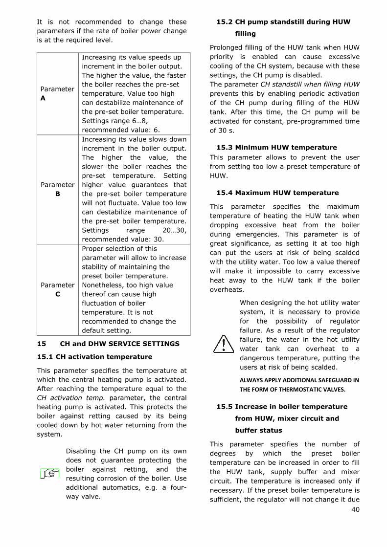
40
It is not recommended to change these
parameters if the rate of boiler power change
is at the required level.
Parameter
A
Increasing its value speeds up
increment in the boiler output.
The higher the value, the faster
the boiler reaches the pre-set
temperature. Value too high
can destabilize maintenance of
the pre-set boiler temperature.
Settings range 6…8,
recommended value: 6.
Parameter
B
Increasing its value slows down
increment in the boiler output.
The higher the value, the
slower the boiler reaches the
pre-set temperature. Setting
higher value guarantees that
the pre-set boiler temperature
will not fluctuate. Value too low
can destabilize maintenance of
the pre-set boiler temperature.
Settings range 20…30,
recommended value: 30.
Parameter
C
Proper selection of this
parameter will allow to increase
stability of maintaining the
preset boiler temperature.
Nonetheless, too high value
thereof can cause high
fluctuation of boiler
temperature. It is not
recommended to change the
default setting.
15 CH and DHW SERVICE SETTINGS
15.1 CH activation temperature
This parameter specifies the temperature at
which the central heating pump is activated.
After reaching the temperature equal to the
CH activation temp. parameter, the central
heating pump is activated. This protects the
boiler against retting caused by its being
cooled down by hot water returning from the
system.
Disabling the CH pump on its own
does not guarantee protecting the
boiler against retting, and the
resulting corrosion of the boiler. Use
additional automatics, e.g. a four-
way valve.
15.2 CH pump standstill during HUW
filling
Prolonged filling of the HUW tank when HUW
priority is enabled can cause excessive
cooling of the CH system, because with these
settings, the CH pump is disabled.
The parameter CH standstill when filling HUW
prevents this by enabling periodic activation
of the CH pump during filling of the HUW
tank. After this time, the CH pump will be
activated for constant, pre-programmed time
of 30 s.
15.3 Minimum HUW temperature
This parameter allows to prevent the user
from setting too low a preset temperature of
HUW.
15.4 Maximum HUW temperature
This parameter specifies the maximum
temperature of heating the HUW tank when
dropping excessive heat from the boiler
during emergencies. This parameter is of
great significance, as setting it at too high
can put the users at risk of being scalded
with the utility water. Too low a value thereof
will make it impossible to carry excessive
heat away to the HUW tank if the boiler
overheats.
When designing the hot utility water
system, it is necessary to provide
for the possibility of regulator
failure. As a result of the regulator
failure, the water in the hot utility
water tank can overheat to a
dangerous temperature, putting the
users at risk of being scalded.
ALWAYS APPLY ADDITIONAL SAFEGUARD IN
THE FORM OF THERMOSTATIC VALVES.
15.5 Increase in boiler temperature
from HUW, mixer circuit and
buffer status
This parameter specifies the number of
degrees by which the preset boiler
temperature can be increased in order to fill
the HUW tank, supply buffer and mixer
circuit. The temperature is increased only if
necessary. If the preset boiler temperature is
sufficient, the regulator will not change it due

41
to necessity of filling the HUW tank,
supplying buffer, or mixer circuit.
Increasing the preset boiler
temperature during filling of the
HUW tank is signalled by letter ―C‖
displayed in the main window.
15.6 Extending HUW pump operation
After filling the HUW tank and disabling the
HUW pump, there is often a problem of the
boiler overheating. It occurs if the preset
domestic hot water temperature is higher
than the preset boiler temperature. In
particular, this problem occurs in the HUW
pump mode: ―SUMMER‖, when the CH pump
is disabled. In order to cool the boiler down,
operation of the HUW pump can be extended
by the time of HUW operation extend.
It is not recommended to set the
time of HUW operation extend. to a
value different than zero if the
preset HUW temperature is higher
than the preset boiler temperature.
15.7 Circulation standstill and
operation time
Circulating pump operates cyclically for
circulation pump operation time. (the
recommended setting is 60-120 s.). The
interval between its period of operation is
defined by the value of parameter circulation
pump standstill time (recommended setting:
15-40 min.).
15.8 Boiler pump
If the CH pump = boiler pump parameter is
set to ―YES‖, the CH pump is not stopped
with HUW priority and in the HUW SUMMER
mode. This parameter is intended only for
hydraulic systems with a heat exchanger,
where the HUW tank is installed on the
closed system side, and the heat exchanger
separates the boiler open system from the
CH closed system. Thanks to continuous
operation of the pump, the heat can be
exchanged from the boiler through the heat
exchanger to the HUW tank.
16 BUFFER SERVICE SETTINGS
16.1 Activate operation
This parameter is used to activate the mode
of operation with the buffer.
16.2 Loading start and stop
temperatures
This parameter defines the upper buffer
temperature, below which the buffer filling
process starts. The buffer filling process is
concluded at the moment when the lower
buffer temperature reaches the value defined
in parameter Buffer filling stop temperature
17 MIXER SERVICE SETTINGS
17.1 MIXER OPERATION
The following options are available:
OFF – mixer servo and mixer pump are
inoperative
CH ON - choose this option if the mixer
circuit feeds radiator system of central
heating. The maximum temperature of mixer
circuit is unlimited, the mixer is fully opened
during alarms, e.g. boiler overheat.
Caution: Do not enable this option if the
system is made of pipes vulnerable to
high temperature; in such case, it is
recommend to set the mixer to FLOOR
h.ON setting.
FLOOR h.ON - choose this option if the mixer
cycle feeds a floor system. The maximum
temperature of the mixer circuit is limited to
the parameter max. mixer temp.
Caution: after choosing the option on FLOOR,
set the parameter max. mixer temp. to such
value that the floor would not be damaged,
and the floor heating users would not be
burned.
Pump only – upon exceeding the pre-set
mixer temperature, supply of the mixer
pump is disabled. When the temperature
drops by 2 oC, it is enabled again. Usually,
this option is used to control the floor
heating pump if it cooperates with a
thermostatic valves without a servo.
Nonetheless, such action is not
recommended. It is recommended to provide
floor heating with a standard heating cycle,
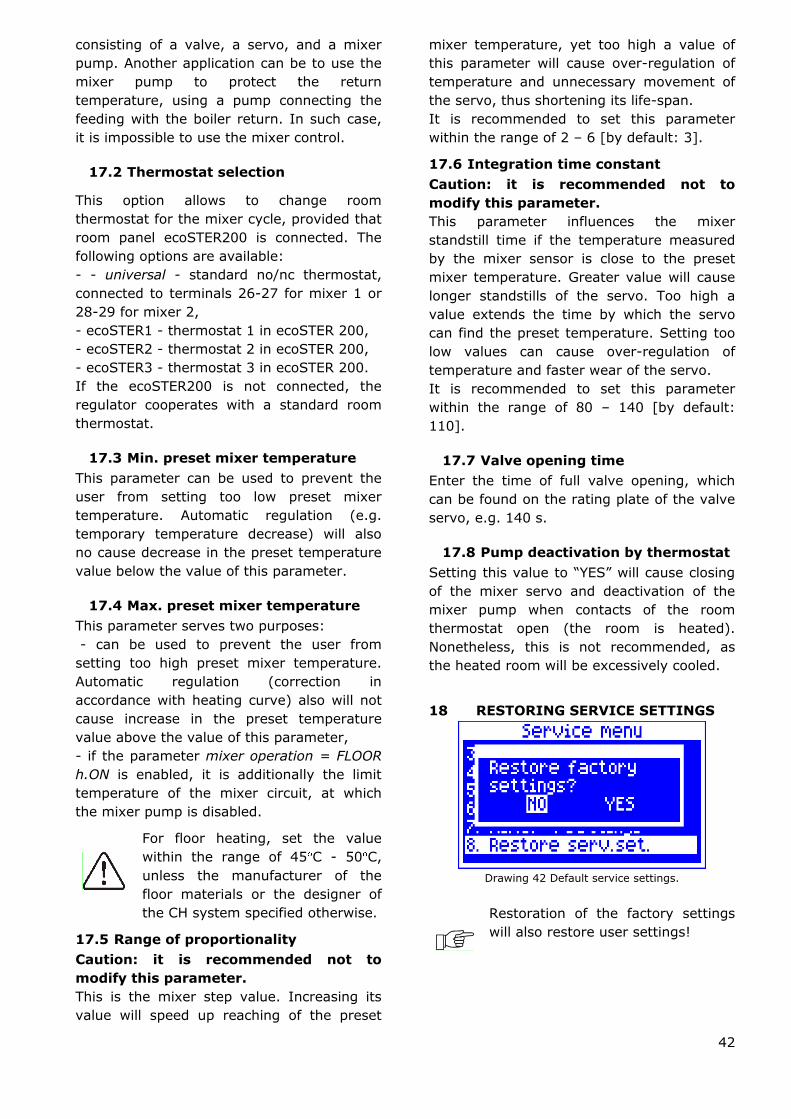
42
consisting of a valve, a servo, and a mixer
pump. Another application can be to use the
mixer pump to protect the return
temperature, using a pump connecting the
feeding with the boiler return. In such case,
it is impossible to use the mixer control.
17.2 Thermostat selection
This option allows to change room
thermostat for the mixer cycle, provided that
room panel ecoSTER200 is connected. The
following options are available:
- - universal - standard no/nc thermostat,
connected to terminals 26-27 for mixer 1 or
28-29 for mixer 2,
- ecoSTER1 - thermostat 1 in ecoSTER 200,
- ecoSTER2 - thermostat 2 in ecoSTER 200,
- ecoSTER3 - thermostat 3 in ecoSTER 200.
If the ecoSTER200 is not connected, the
regulator cooperates with a standard room
thermostat.
17.3 Min. preset mixer temperature
This parameter can be used to prevent the
user from setting too low preset mixer
temperature. Automatic regulation (e.g.
temporary temperature decrease) will also
no cause decrease in the preset temperature
value below the value of this parameter.
17.4 Max. preset mixer temperature
This parameter serves two purposes:
- can be used to prevent the user from
setting too high preset mixer temperature.
Automatic regulation (correction in
accordance with heating curve) also will not
cause increase in the preset temperature
value above the value of this parameter,
- if the parameter mixer operation = FLOOR
h.ON is enabled, it is additionally the limit
temperature of the mixer circuit, at which
the mixer pump is disabled.
For floor heating, set the value
within the range of 45 C - 50 C,
unless the manufacturer of the
floor materials or the designer of
the CH system specified otherwise.
17.5 Range of proportionality
Caution: it is recommended not to
modify this parameter.
This is the mixer step value. Increasing its
value will speed up reaching of the preset
mixer temperature, yet too high a value of
this parameter will cause over-regulation of
temperature and unnecessary movement of
the servo, thus shortening its life-span.
It is recommended to set this parameter
within the range of 2 – 6 [by default: 3].
17.6 Integration time constant
Caution: it is recommended not to
modify this parameter.
This parameter influences the mixer
standstill time if the temperature measured
by the mixer sensor is close to the preset
mixer temperature. Greater value will cause
longer standstills of the servo. Too high a
value extends the time by which the servo
can find the preset temperature. Setting too
low values can cause over-regulation of
temperature and faster wear of the servo.
It is recommended to set this parameter
within the range of 80 – 140 [by default:
110].
17.7 Valve opening time
Enter the time of full valve opening, which
can be found on the rating plate of the valve
servo, e.g. 140 s.
17.8 Pump deactivation by thermostat
Setting this value to ―YES‖ will cause closing
of the mixer servo and deactivation of the
mixer pump when contacts of the room
thermostat open (the room is heated).
Nonetheless, this is not recommended, as
the heated room will be excessively cooled.
18 RESTORING SERVICE SETTINGS
Drawing 42 Default service settings.
Restoration of the factory settings
will also restore user settings!

43
19 DESCRIPTION OF ALARMS
19.1 Exhaust temperature sensor damage
This alarm will be triggered in the case of
damaging the exhaust temperature sensor,
or upon exceeding this sensor‘s
measurement range. If this alarm occurs,
automatic boiler operation is disabled, only
the CH pump is active.
Cancel this alarm by pressing the TOUCH and
PLAY button, or by restarting the regulator.
Inspect the sensor and replace it if
necessary.
See how to check the temperature
sensor in point 13.10.
Drawing 43 View of exhaust sensor damage alarm.
19.2 Exceeding max. boiler
temperature
Protection against boiler overheating is
twofold. First, after exceeding the boiler
cooling temp, the regulator tries to decrease
the boiler temperature by dropping the
excessive heat to the HUW tank and by
opening the mixer servo (only if mixer cycle
= on CH).
If the temperature measured by the HUW
sensor exceeds the value of Max. HUW
temp., the HUW pump will be disabled in
order to protect the users against scalding. If
the boiler temperature drops, the regulator
will resume normal operation. Whereas is the
temperature continues to rise (reaches
95 C), fuel feeder and fan are disabled and
a permanent boiler overheating alarm – with
sound signalling – is activated.
Cancel this alarm by pressing the TOUCH and
PLAY button, or by restarting the regulator.
Caution: placing the sensor beyond
the boiler water jacket is not
recommended, as it can delay
detection of the boiler overheating!
Drawing 44 View of boiler overheat alarm.
19.3 Exceeding max. feeder
temperature
This alarm will occur after the feeder
temperature exceeds the service parameter:
Service settings> Boiler settings> Max.
feeder temperature
If the feeder temperature exceeds this value,
the regulator will enable the feeder for a
constant, programmed time and will activate
the poker. The airflow is disabled and the
pumps are enabled. After „pushing the fuel
out‖, the regulator disables the feeder and
does not activate it again, even if the feeder
temperature is still high.
This alarm can be cancelled only after the
feeder temperature decreases, by pressing
the encoder knob or by restarting the
regulator.
The function of protection against
flame recession is inoperative if the
feeder sensor is disconnected or
damaged.
The function of protection against
flame recession is inoperative if the
regulator is not powered.
The ecoMAX800P1-L regulator
cannot be used as the only
protection against flame recession
in a boiler. Use additional protective
automatics.
The function of protection against
flame recession can be disabled, see
point 14.16.

44
19.4 Damage to boiler temp. sensor
This alarm will be produced in the case of
damage to the boiler sensor, or after
exceeding its measuring range. The alarm
activates the CH and HUW pumps, as well as
the mixer pump, in order to cool the boiler
down.
Cancel the alarm by pressing the TOUCH and
PLAY button, or by restarting the regulator.
Check the sensor, and possibly replace it.
The method of checking the
temperature sensor is described in
point 13.10.
Drawing 45 View of boiler temperature sensor failure
alarm.
19.5 Feeder temperature sensor
damage
This alarm will occur in the case of damage
to the feeder sensor, or after exceeding its
measuring range. The alarm causes
activation of the CH and DHW pumps in
order to cool the boiler down.
Cancel the alarm by pressing the TOUCH and
PLAY button, or by restarting the regulator.
Check the sensor, and possibly replace it.
The method of checking the
temperature sensor is described in
point 13.10.
The regulator can operate if the
feeder temp. sensor is disconnected,
after setting the parameter max.
feeder temp. =0. Nonetheless, it is
not recommended, as in this case
the function of protection against
the flame recession into the fuel
hopper is disabled.
Drawing 46 View of feeder sensor failure alarm.
19.6 No communication
The control panel is connected with the
executive module via digital communication
link RS485. If this link is damaged, the
following alarm will be displayed:
„Caution! No communication.‖
The regulator does not disable regulation and
operates as usual, with the pre-programmed
parameters. If any other alarm occur, it will
take action in accordance with the given
alarm.
Check the connection the control panel and
repair or replace it respectively.
19.7 Unsuccessful firing-up attempt
This alarm will occur after third unsuccessful
attempt to automatically fire up the furnace.
In the case of this alarm, all pumps are
deactivated in order to avoid excessive
cooling of the boiler.
Cancel this alarm by pressing the TOUCH and
PLAY button, or by restarting the regulator.
This alarm can be caused by, e.g.: faulty
lighter or lack of fuel in the tank.
19.8 Unsuccessful attempt to fill the
tank
This is a so-called noiseless alarm prompt. It
is triggered after second unsuccessful
attempt to add fuel from the auxiliary tank
(bunker). It is displayed if the boiler tank
cannot be filled within an hour of the
secondary feeder operation. This signal does
not disable automatic boiler operation,
merely display of a warning on the panel.
Cancel this alarm by pressing the TOUCH and
PLAY button, or by restarting the regulator.

45
20 OTHER ALARMS
20.1 Power supply decay
In the cases of power supply failure, the
regulator will resume the operation mode in
which it was before the failure.
20.2 Protection against freezing
If the boiler temperature drops below 5 C,
the CH pump will be enabled, thus forcing
circulation of the boiler water. This will delay
the process of water freezing, yet in the case
of great frost or shortage of power, it will not
protect the system against freezing.
20.3 Function of protecting pumps
against stagnation
The regulator protects the CH, HUW and
mixer circuit pumps against stagnation. It
does so by activating them periodically
(every 167 h for several seconds). This
protects the pumps against immobilization
due to sedimentation of boiler scale. For this
reason, the regulator power supply should be
connected also when in the boiler is not in
use. This function can be enabled also when
the regulator is turned off, via keyboard
(regulator in STAND-BY).
21 REPLACEMENT OF PARTS AND
SUBASSEMBLIES
When ordering parts and subassemblies,
please specify necessary information read off
the rating plate. It is best to give the
regulator serial number. If the serial number
is not known, please specify the model and
type of the regulation, as well as the year of
its production.
The regulator serial number can be
found on a rating plate of the
executive module.
21.1 Replacing mains fuse
The mains fuses are situated in the executive
modules. It protects the regulator along with
connected devices.
Please use time-delay fuses, porcelain,
5x20 mm, of nominal burnout current 6,3A.
Drawing 47 Fuse replacement, where: 1 – fuse, 2 – fuse
socket.
In order to remove the fuse, push in its
socket with a flat screwdriver and turn it
counter clockwise.
21.2 Control panel replacement
When replacing the whole control panel,
check compatibility of the new panel
software with the executive panel A
software. Compatibility is maintained if the
first number of software in the control panel
and in the executive module is identical. In
the example below, the software versions are
compatible, as the first number ,,01‖ is the
same for both subassemblies.

46
Examples of software numbers:
Control panel Executive module
01.10.010. 01.11.026.R1
The software numbers can be read
on the rating plates of the
subassemblies, or in the menu
Information.
Drawing 48 Software versions in the Information menu.
The regulator can operate
improperly if the control panel is
incompatible with the executive
module.
21.3 Executive module replacement
The requirements are the same as those for
replacement of the control panel, point 21.2.

22 Troubleshooting
Faults Hints
1. The display is blank
despite connection to
power supply.
Check:
if the main fuse is burnt-out, replace if so,
if the lead connecting the panel with the module is properly
plugged in, and if it‘s not damaged.
2. Preset CH temperature
on the display is
different than the
programmed one.
Check:
if the HUW tank is not being filled, and if the preset HUW
temperature is set higher than the preset boiler temperature; if
so, the difference in readings will disappear after filling the HUW
tank alternatively - decrease the preset HUW temperature,
if the time periods are on – disable Night-time decreases.
3. CH pump is inoperative.
Check:
whether the boiler temperature exceeded the parameter CH
activation temp. – wait or decrease the CH activation temp.
if the HUW priority, which blocks the central heating pump, is
enabled – disable the priority by setting the HUW mode to No
priority,
whether the central heating pump is not damaged or clogged.
4. The fan is inoperative.
increase the fan speed (parameters for blow-in output),
check if the safety temperature limiter STB jumper is on
terminals 1-2 (the jumper should be placed only if no proper STB
temperature limiter is connected),
if the boiler manufacturer equipped it with a temperature limiter
STB with manual return to its initial position, unlock it by
removing the lid and pushing the button, in accordance with the
documentation provided by the boiler manufacturer,
check the fan and replace it if necessary.
5. Fuel feeder inoperative/
fails to feed.
Check if the feeder leads are properly connected to terminals
If temperature limiter STB is connected to terminals 1-2, check if
the circuit is not cut off due to boiler overheating,
Check if the feeder motor is in working order,
If you can hear the motor running, but the fuel is not fed, check
the feeder in accordance with the boiler manual.
6. When the Individual
Fuzzy Logic mode is on,
the fuel is not
completely burned,
there are unburned
particles of fuel in the
ash.
Increase Individual Fuzzy Logic airflow correction, point 8.7,
See if the unburned fuel comes from operation in the
SUPERVISION mode - adjust the SUPERVISION mode
parameters,
Check if the unburned fuel is caused by frequent switching from
SUPERVISION to OPERATION,
Make sure if correct type of boiler is selected, point 23.1,
Open the fan flap and/or fan return flap to the maximum,
Check the ducts which feed air into the furnace,
Unseal the window in the boiler room to provide sufficient
amounts of air.
7. When the Individual
Fuzzy Logic mode is on,
the fuel burns out too
intensively.
Decrease Fuzzy Logic airflow correction, point 8.7,
See if the excessive burning of fuel comes from operation in the
SUPERVISION mode - adjust the SUPERVISION mode as per
point 8.9.
Make sure if correct type of boiler is selected, point 23.1.
8. The temperature is
measured incorrectly.
Check if there is good thermal contact between the temperature
sensor and the measured surface,
Whether the sensor lead is not placed too close to the mains
cable,
If the sensor is connected to the terminal,
Whether the sensor is not damaged – check it in accordance with
point 13.10.

9. in the DHW=SUMMER
mode, the radiators are
hot and the boiler
overheats.
Increase the parameter HUW operation extend. in order to cool
down the boiler.
10. the DHW pump is active
even if the DHW tank
has been filled.
Set the parameter HUW operation extend to 0.
11. The boiler overheats
despite disabled airflow.
The reason can be faulty chimney installation (no protection
against excessive chimney draught).
12. In a hydraulic system
with a mixing valve and
servo - the mixer fails
to open.
The reason may be activity of the return protection function,
point 14.7. If the return protection function is active, check if the
sensor for water returning to the boiler is thermally insulated
from its surroundings, and improve contact with the pipe by
applying thermally conductive paste. Increase the pre-set boiler
temperature in order to provide power reserve needed to heat
the return water. Check if the hydraulic system is properly
made, i.e. after closing the valve, the return temperature must
be able to exceed the parameter Min. return temp. value.
The reason can be that the HUW tank is being filled with HUW
priority enabled. Wait until the HUW is filled, or disable the HUW
priority.
The reason can be active SUMMER function.
The reason can be an on-going calibration of the mixer valve,
wait until the calibration is complete. Active calibration is
signalled with a ―CAL‖ message in the menu INFORMATION –
MIXER INFO.

23 Regulator setup by boiler manufacturer.
CAUTION: THE INDIVIDUAL FUZZY LOGIC PROGRAM IS SELECTED INDIVIDUALLY TO
THE GIVEN BOILER TYPE. MAKE SURE THAT THE FITTINGS FOR BOILERS TESTED IN
THE PLUM LABORATORIES ARE COMPATIBLE WITH FITTINGS FOR SOLD BOILERS. IT IS
INADMISSIBLE TO REPLACE THE FEEDER AND FAN TO OTHER TYPES AS WELL AS
MAKING OTHER CONSTRUCTIONAL MODIFICATIONS WHICH CAN HAVE IMPACT ON
COMBUSTION PROCESS.
23.1 Activating Individual Fuzzy Logic and changing boiler type
In order to activate the Individual Fuzzy Logic mode, enter MENU:
MENU > Regulation mode In this menu, find and confirm Individual Fuzzy Logic mode If the
boiler operation modes list is unavailable, and clicking the aforementioned menu triggers a
message ―Function unavailable‖, it means that the regulator operates only in the STANDARD
mode, Individual Fuzzy Logic control is disabled and unavailable for the given setup of a boiler.
To change the type of boiler, furnace, enter hidden MENU:
MENU> Service settings > (enter special password)
The special password is made available only to boiler manufacturers and authorized fitters.
Drawing 49 Selection of boiler type and output7.
Caution: selecting an incorrect boiler type, which was not examined in the
PLUM laboratories, can damage the boiler during its operation.
Settings for individual boilers require arrangements between the boiler manufacturer and the
PLUM sp. z o.o. company.
In order to apply the changes, it is necessary to disconnect and reconnect the regulator mains
supply.
7 The regulator allows to select only those types of boilers and fuel, which were tested in the
laboratory of PLUM sp. z o.o.