Cleaver-Brooks Engineered Boiler Systems Manufacturers of ...

BOILER FEED amp PUMP SIZINGPresented by Cleaver-Brooks Steve Connorand Grundfosrsquo Jim Swetye
TODAYrsquoS AGENDAbull Brief review of a typical steam systembull The boiler size range pressures and types we will be
addressing todaybull Methods and importance of capturing condensate for boiler feedbull Typical pumps used for boiler feed water dischargebull Typical piping methods usedbull Pump sizing criteriabull Criteria for calculating the base flow for the pumpbull Understanding TDH and NPSHbull Sizing a pump for a specific application (example)bull Reading the pump curve for final selectionbull Summary and QampA
2
T
T
T
T
T
LegendSteamCond
Vapor
H P Cond ReturnVent
D A TankD A Tank
Feed PumpBoiler
Strainer
Trap Trap
Trap TrapTT
TT
DA Tank
TT
TT
TTT
Legend
HP SteamPRV
LP Steam
Trap
LP Condensate Return
Cond Rcvramp Pump
MotiveForce
Flash
TYPICAL STEAM SYSTEM
33
BOILER SIZES AND FEED PUMP SIZES
Boiler HP Range
Boiler Pressure
Range
Typical Feed Pump Type
Typical Max Feed
Pump Flow
Range
Typical Max Feed
Pump Head
Where Used
100 to 1200
150 to 500 psi
Vertical inline
multistage regenerative
turbines
10 to 125 gpm 1250 feet
General industry
institutional universities
some commercial
buildings
4
FIRETUBE
Watertube (IWT)
Integral burner
Gun burner5
HORIZONTAL FIRETUBE BOILERSThe Dryback
Refractory Filled Door 1 2
3
4
Baffles
Tubesheet
Two (2) Tubesheets6
WATERTUBE OR IWT
7
THE WATERTUBE BOILER
bull Opposite of Firetubebull Water in the Tubesbull Natural and Forced Circulationbull Large Furnacebull Upper amp Lower Drums orbull Headers
Upper Steam Drum
Lower Mud Drum
Furnace
Outlet nozzle location
8
FLUE GAS SEALING
100 Membrane Construction
Tangent Tube Furnace Design Also Available
9
CONDENSATE IS LIQUID GOLD
A finite resource
10
TYPICAL STEAM SYSTEM
T
T
T
T
T
LegendSteamCond
Vapor
H P Cond Return
D A TankD A Tank
Feed PumpBoiler
Strainer
Trap Trap
TrapTT
TT
DA Tank
TT
TT
TTT
Legend
Trap
HP SteamPRV
LP Steam
Trap
LP Condensate Return
MotiveForce
FlashCondensate tank amp Pump system
11
CONDENSATE RETURN PUMPS
12
FLASH STEAM
T
T
T
T
T
H P Condensate Return
Cond Pump
D A TankD A Tank
Feed PumpBoiler
Strainer
Trap Trap
Trap TrapTT
TT
TT
TT
TTT
HP SteamPRV 15 psig
250 FLP Steam
150 psig366 F
TrapMotiveForce
Feed Tank or DA
13
Flash Tank
Low pressure condensate line
Flash Tank Flash Tank wEconomizer
Use flash steam for heating or deaerating Why not recover the heat from the hot condensate
14
HOT CONDENSATE RETURNED
DeaeratorBoiler Feed System
A vented receiver wastes energy
Pressurized receiver saves energy
Steam diffusing tube
15
Steam
HP Return
Vent
Exhaust OrFlash Steam
ToBoiler
Boiler FeedWater Pump(s)
OverflowDrainer
Cold Make-UpWater
LP Condensate
Make-Up Valve
Check Valve
PRV
Level control
16
SPRAY DEAERATOR
Spray cone
17
TRAY DEAERATOR
steam
Trays
18
PACKED COLUMN DA
19
BOILER FEED WATER TANKSSpray DA Tray DA Column DA
Vented Receiver
20
T
T
T
T
TH P Condensate Return
Cond Pump D A TankD A Tank
Feed PumpBoiler
Strainer
Trap Trap
TrapTrapTT
TT
TT
TT
TTT
HP SteamPRV 15 psig
250 F
LP Steam150 psig366 F
TrapMotiveForce
Feed Tank or DA
HP CONDENSATE RECOVERY
21
HIGH PRESSURE CONDENSATE RECEIVER
bull Takes high pressure condensate directly from the user
bull No need to deaeratebull Pump directly into boilerbull Feed the HPR from the DA
22
BOILER FEED WATER TANK OPTIONSSpray DA Tray DA Column DA
Vented Receiver
HPCR
23
FEED WATER SYSTEMSFor multiple boiler Installations
24
METHOD 1 ndashDirect feed for multiple boilers
Deaerator
Boiler A
Boiler AControlle
r4-20mA signal directly to
Grundfos E-pump instead of
control valve
Boiler BBoiler BControlle
r4-20mA signal directly to
Grundfos E-pump instead of
control valve
25
METHOD 2 ndashBooster sets for multiple boilers
Deaerator Pressure sensor
Bypass
Multiple pump
controller
26
STEAM BOILER PUMP APPLICATIONS AND TYPESBoiler feed pumpsCollection tank pumpsWater treatment pumpsCondensate return pumpsDeaerator tank recycle pumpsDeaerator vacuum pumps (vacuum deaerator tanks only)Economizer pumps
27
SIZING COMPLEXITY FOR BOILER FEED PUMPS
28
BASE FLOW RATE CALCULATION
Base flow = Boiler maximum capacity horsepower X 0069 X C
bull C = 15 for OnOff intermittent operation
bull C = 115 for continuous feed operation
29
ADD FOR CONTINUOUS BOILER BLOWDOWN FLOW
To the Base flow we MIGHT add if specified
For Continuous Boiler Blowdown flowbull Approximately 5 to10 of the pumprsquos flow
rate at the Best Efficiency Point
30
ADD FOR BYPASS RECIRCULATION FLOWCertain feed system control modes require the use of a bypass line back to the source tank ndash such as back to the deaerator tank
Method
NamePump Speed
TypeDuty
Is orifice flow by-pass line
required1 OnOff control and fixed speed pumps Fixed Intermittent No2 Feed control valve and fixed speed pumps Fixed Continuous Yes3 Feed control valve and variable speed pumps Variable Continuous Yes4 Variable speed pumps only (no control valve) Variable Continuous No
31
RECIRCULATION FLOW
bull The solid curve below shows the minimum flow rate as a percentage of the nominal flow rate in relation to the liquid temperature
bull Ignore the dotted line which indicates a pump with special high-temperature construction
32
CALCULATING REQUIRED FEED PUMP HEAD
+ Suction side head+ Discharge side head= Total Dynamic Head
Elevation of DA tank
Elevation of boiler
33
FEED VALVE IMPACTS PUMPING HEAD CALCULATION
34
CALCULATING THE HEADFOR THE FEED PUMP1) At the duty point flow rateHead in feet = Boiler operating pressure X 231 X 103 divide Liquid Specific Gravity
Example Head = 130 psi X 231 X 103 divide 0953 = 324 feet
2) At shutoff head (dead head)Head in feet = Pressure relief valve setting X 231 X 103 divide Liquid Specific Gravity
Example Head = 160 psi X 231 X 103 divide 0953 = 400 feet
35
NPSH ndashFORMULA FOR CALCULATION
NPSHr is obtained from the pump curve
Add two to four feet of safety factor to the NPSHr stated on the curve
NPSHa is calculated
+ Absolute pressure in deaerator tank
plusmn Elevation of minimum water level in tank above feed pump
- Vapor pressure of water in deaerator tank
- Suction line friction loss
= Net Positive Suction Head Available
To avoid cavitation NPSHa must be greater than NPSHr
36
NPSH AND ELEVATIONDeaerator
tank
Boiler feed
pumps
Minimum water level in DA tank
Location of eye of lowest impeller
Difference in elevation
37
NPSH AND SUCTION LINE CONSIDERATIONS
Critical suction line considerations here
38
Check list for boiler feed pump selection
Step Action
1 Determine cont rol method to be used
2 Calculate BASE flow rate
3 Add for Cont inuous Boiler Blowdown flow
4 Add for by-pass flow if required
5 Sum of base flow by-pass flow and Blowdown flow is the total flow required
6 Calculate BASE pumping head
7 Add for all suct ion piping head components
8 Add for all discharge piping system head components (including feed valve if required)
9 Sum of all head components = total pumping head
10 Calculate head at boiler safety vavle set t ing plus three percent
11 Determine deaerator tank water temperature
12 Perform NPSHa calculat ion
13 Make preliminary pump select ion
14 Assure that shutoff head equals or exceeds three percent above safety valve set t ing
15 Check NPSHr versus NPSHa
16 Assure material compat ibilit y - chemical and temperature
17 Make final pump select ion
39
BOILER FEED PUMPS USEFUL FORMULAS
40
SPECIFICATION FOR EXERCISEa) Control Method Continuous duty fixed speed pump with bypass line and feed valveb) Boiler maximum capacity = 250 HPc) Boiler safety valve setting = 125 psigd) Pressure safety factor = 3 above boilerrsquos safety valve settinge) Boiler operating pressure = 100 psigf) Continuous Boiler Blowdown flow - Requiredg) Bypass recirculation flow ndash Requiredh) Altitude ndash Sea leveli) Pressure in deaerator tank above atmospheric pressure = 5 psi (147 + 5 = 197 psi absolute)j) Height of deaerator tank minimum water level above pumprsquos first impeller = 10 feetk) Friction line loss through suction piping = 5 footl) Friction loss through suction side fittings = 5 footm) Friction loss through suction side valves = Nonen) Friction loss through suction side strainer = 1 feeto) Friction loss through discharge piping = 1 footp) Friction loss through discharge side fittings = 1 footq) Pressure drop across feed valve ndash 15 psir) Elevation of boiler maximum water level above pumprsquos discharge port = 5 feets) Liquid Specific Gravity = 0953t) Temperature of water in deaerator tank = 227 degrees Fu) Vapor pressure in deaerator tank = 197 psiv) Pump materials all 316 stainless steel to resist treatment chemicalsw) Mechanical seal to be silicon carbidesilicon carbideEPDM to withstand liquid temperature
41
Feed pumps
CONTROL METHOD
Fixed speed pumps with feed valve and recirculation line
Recirc line
Feed valve
42
STEP 1 ndashDetermine control methodFeed valve controlled system with a continuous duty fixed speed pump has been specified
XStep Action
1 Determine cont rol method to be used
2 Calculate BASE flow rate
3 Add for Cont inuous Boiler Blowdown flow
4 Add for by-pass flow if required
5 Sum of base flow by-pass flow and Blowdown flow is the total flow required
6 Calculate BASE pumping head
7 Add for all suct ion piping head components
8 Add for all discharge piping system head components (including feed valve if required)
9 Sum of all head components = total pumping head
10 Calculate head at boiler safety vavle set t ing plus three percent
11 Determine deaerator tank water temperature
12 Perform NPSHa calculat ion
13 Make preliminary pump select ion
14 Assure that shutoff head equals or exceeds three percent above safety valve set t ing
15 Check NPSHr versus NPSHa
16 Assure material compat ibilit y - chemical and temperature
17 Make final pump select ion
43
STEP 2 ndashCalculate the BASE feed pump flow rate
The formula for this calculation is
bull Boiler maximum capacity in horsepower X 0069 X C
bull The maximum capacity in boiler horsepower is 250
bull The C factor is 115 for continuous duty
Therefore
250 X 0069 X 115 = 20 gpm = BASE flow rate
44
STEP 3 ndashContinuous Boiler Blowdown Flow
Determination
1 The BASE flow rate has been established at 20 gpm
2 We will on next slide need to add for bypass flow which can add 10 to 20 percent to the BASE flow rate
3 Blowdown flow is to be approximately 10 percent of flow at pumprsquos Best Efficiency Point
4 So the total boiler blowdown flow required is approximately 3 gpm
45
STEP 4 ndashAdd for by-pass flow
bull Control is via feed valve with fixed speed pump and for continuous dutybull A bypass will be required
bull Solid curve to right shows minimum flow rate as a percentage of nominal flow rate in relation to liquid temperature
bull Ignore dotted line which indicates a pump with special high-temperature construction
bull At 227degF we require a bypass flow that is about 20 of BEP flow
bull Presuming we can find a pump with BEP at about 25 or so gpm the bypass flow must be about 5 gpm
46
STEP 5 ndashCalculate total flow requiredbull BASE flow = 20 gpmbull Blowdown flow = 3 gpmbull Recirculation flow = 5 gpmbull Total flow required = 28 gpm
XXXX
X
Step Action
1 Determine cont rol method to be used
2 Calculate BASE flow rate
3 Add for Cont inuous Boiler Blowdown flow
4 Add for by-pass flow if required
5 Sum of base flow by-pass flow and Blowdown flow is the total flow required
6 Calculate BASE pumping head
7 Add for all suct ion piping head components
8 Add for all discharge piping system head components (including feed valve if required)
9 Sum of all head components = total pumping head
10 Calculate head at boiler safety vavle set t ing plus three percent
11 Determine deaerator tank water temperature
12 Perform NPSHa calculat ion
13 Make preliminary pump select ion
14 Assure that shutoff head equals or exceeds three percent above safety valve set t ing
15 Check NPSHr versus NPSHa
16 Assure material compat ibilit y - chemical and temperature
17 Make final pump select ion
47
STEP 6 ndashCalculate BASE pumping head
Boiler operating pressure setting + 3
Formula BASE head in feet = Boiler operating pressure X 231 X 103 divide Specific Gravity
BASE head = 100 psi X 231 X 103 divide 0953 = 250 feet
48
STEP 7 ndashAdd for suction piping system head components
From specificationAbsolute pressure on deaerator tank = 197 psi X 231 = - 46 feetWater elevation above first impeller = - 10 feetFriction loss through suction piping = + 5 feetFriction loss through suction fittings = + 5 feetFriction loss through suction side valves and strainer = + 1 feet
Total = - 54 feet
49
STEP 8 ndashAdd for discharge piping system head components
From specificationFriction loss through discharge piping = + 1 footFriction loss through discharge fittings = + 1 footFriction loss through feed valve is 15 psi X 231 = + 35 feetElevation of boiler maximum water level above pump = + 5 feet
Total = + 42 feet
50
STEP 9 ndashSum of all head components
BASE head with safety factor = + 250 feetSuction side piping system head = - 54 feetDischarge side piping system head = + 42 feet
Total = + 238 feet
51
STEP 10 ndashPressure safety valve considerations At shutoff head (dead head)Head in feet = Pressure relief valve setting X 231 X 103 divide Liquid Specific GravityExample Head = 125 psi X 231 X 103 divide 0953 = 312 feet
XXXXXXXXX
XStep Action
1 Determine cont rol method to be used
2 Calculate BASE flow rate
3 Add for Cont inuous Boiler Blowdown flow
4 Add for by-pass flow if required
5 Sum of base flow by-pass flow and Blowdown flow is the total flow required
6 Calculate BASE pumping head
7 Add for all suct ion piping head components
8 Add for all discharge piping system head components (including feed valve if required)
9 Sum of all head components = total pumping head
10 Calculate head at boiler safety vavle set t ing plus three percent
11 Determine deaerator tank water temperature
12 Perform NPSHa calculat ion
13 Make preliminary pump select ion
14 Assure that shutoff head equals or exceeds three percent above safety valve set t ing
15 Check NPSHr versus NPSHa
16 Assure material compat ibilit y - chemical and temperature
17 Make final pump select ion
52
STEP 11 ndashDetermine deaerator tank water temperature
From specification 227degF
53
STEP 12 ndashNPSHa calculation
NPSHa equation
plusmn Elevation + Absolute pressure ndash Vapor Pressure ndash Suction Line Friction = NPSHa
10 feet + (197 psi X 231) - (197 psi X 231) - 2 feet = NPSHa10 feet + 46 feet - 46 feet - 2 feet = 8 feet NPSHa
54
STEP 13 ndashPreliminary pump selection
Conditions of Service Flow = 28 gpmHead = 238 Feet
Does this 10 stage pump pump meet the required flow and head conditions of service
YES
55
STEP 14 ndashPressure safety valve considerations
56
STEP 15 ndashCheck NPSHa vs NPSHr
Conditions of ServiceFlow = 28gpmHead = 238 FeetNPSHa = 8 Feet
bull Pump meets or exceeds flowhead requirement
bull Low-NPSHr first stage = 4 feet required
bull NPSHr safety factor = 2 to 4 feet
bull Target NPSHr = 8 feetbull NPSHa = 8 feet
Does NPSHa equal or exceed NPSHr
YES57
STEP 15 ndashNPSH - ContinuedConditions of Service Flow = 28 gpm Head = 238 Feet NPSHa = 8 FeetThe NPSHa is equal to or exceeds the NPSHr of 8 feet
XXXXXXXXXX
XXXXX
Step Action
1 Determine cont rol method to be used
2 Calculate BASE flow rate
3 Add for Cont inuous Boiler Blowdown flow
4 Add for by-pass flow if required
5 Sum of base flow by-pass flow and Blowdown flow is the total flow required
6 Calculate BASE pumping head
7 Add for all suct ion piping head components
8 Add for all discharge piping system head components (including feed valve if required)
9 Sum of all head components = total pumping head
10 Calculate head at boiler safety vavle set t ing plus three percent
11 Determine deaerator tank water temperature
12 Perform NPSHa calculat ion
13 Make preliminary pump select ion
14 Assure that shutoff head equals or exceeds three percent above safety valve set t ing
15 Check NPSHr versus NPSHa
16 Assure material compat ibilit y - chemical and temperature
17 Make final pump select ion
58
STEP 16 ndashCheck material compatibility
bull Pump materials 316 stainless steelbull Mechanical seal materials Silicon carbidesilicon
carbideEPDM
59
STEP 17 ndashFinal pump selectionPump meets all specification requirements
XXXXXXXXX
X
XXXXXXX
Step Action
1 Determine cont rol method to be used
2 Calculate BASE flow rate
3 Add for Cont inuous Boiler Blowdown flow
4 Add for by-pass flow if required
5 Sum of base flow by-pass flow and Blowdown flow is the total flow required
6 Calculate BASE pumping head
7 Add for all suct ion piping head components
8 Add for all discharge piping system head components (including feed valve if required)
9 Sum of all head components = total pumping head
10 Calculate head at boiler safety vavle set t ing plus three percent
11 Determine deaerator tank water temperature
12 Perform NPSHa calculat ion
13 Make preliminary pump select ion
14 Assure that shutoff head equals or exceeds three percent above safety valve set t ing
15 Check NPSHr versus NPSHa
16 Assure material compat ibilit y - chemical and temperature
17 Make final pump select ion
60
61
SUMMARYbull Steam condensate is a very valuable commodity which needs to saved and used as much as possiblebull Most commonly used boilers for process are industrial firetubes and watertube boilers IWTsbull High pressure condensate flash steam can be used for various purposes such as unit heaters or the
DAbull Condensate can be returned to vented receivers or pressurized deaerators (Spray Tray amp Column)bull Sometimes high pressure condensate receivers are employed Save considerable lossesbull Boiler feed pump selection involves 17 decision points which need to be carefully consideredbull Calculating the pumprsquos base flow rate differs when the pump operates continuously (15 safety factor)
or onoff (50 safety factor)bull Sometimes the base flow rate needs to include for continuous pump re-circulation and maybe for
continuous blow downbull Total Dynamic Head (TDH) is a that pressure the pump must overcome to get water in the boiler and
includes the positive pressure at the pumprsquos inlet after suction pipe losses and the piping losses through the discharge piping before overcoming the boilerrsquos operating pressure
bull Net Positive Suction Head (NPSH) is the pressure required at the pumprsquos suction to mitigate cavitation
bull NPSHA is the NPSH available after all the friction losses on the suction side have been determined in light of the pumprsquos minimum and maximum flow rates
bull The seal selection for the pump is very important and can vary based on the boilerrsquos operating pressuretemperature chemicals in the feed water etc
62
Gregg Achtenhagengachtenhagencleaverbrookscom
Jim Swetyejswetyegrundfoscom
QUESTIONS
63
Over 25000 Grundfos parts are available through your local Cleaver-Brooks RepresentativeVisit cleaverbrookscomreps for all boiler sales and service
| Step | Action | |||||
| 1 | Determine control method to be used | |||||
| 2 | Calculate BASE flow rate | |||||
| 3 | Add for Continuous Boiler Blowdown flow | |||||
| 4 | Add for by-pass flow if required | |||||
| 5 | Sum of base flow by-pass flow and Blowdown flow is the total flow required | |||||
| 6 | Calculate BASE pumping head | |||||
| 7 | Add for all suction piping head components | |||||
| 8 | Add for all discharge piping system head components (including feed valve if required) | |||||
| 9 | Sum of all head components = total pumping head | |||||
| 10 | Calculate head at boiler safety vavle setting plus three percent | |||||
| 11 | Determine deaerator tank water temperature | |||||
| 12 | Perform NPSHa calculation | |||||
| 13 | Make preliminary pump selection | |||||
| 14 | Assure that shutoff head equals or exceeds three percent above safety valve setting | |||||
| 15 | Check NPSHr versus NPSHa | |||||
| 16 | Assure material compatibility - chemical and temperature | |||||
| 17 | Make final pump selection |
| 1 Base flow calculation equation | |||||
| Boiler maximum capacity horsepower X 0069 X C = Base flow rate | |||||
| C = 150 for OnOff intermittent operation | |||||
| C = 115 for continuous feed operation | |||||
| 2 Determine BASE head for feed pump | |||||
| Formula based on Safety Valve setting | |||||
| Pump head in feet = Maximum pressure X 231 X 103 divide Liquid Specific Gravity | |||||
| 3 Head components on suction side of piping system | |||||
| Pressure above atmospheric on deaerator converted to feet of head = | feet | ||||
| Elevation difference between minimum deaerator water level and pump inlet = | feet | ||||
| Suction pipe friction loss = | feet | ||||
| Suction fitting friction loss = | feet | ||||
| Suction line valves and strainer friction loss = | feet | ||||
| Total = | feet | ||||
| 4 Head components on discharge side of piping system | |||||
| Friction loss through discharge piping = | feet | ||||
| Friction loss through discharge fittings = | feet | ||||
| Friction loss through feed valve = | feet | ||||
| Elevation of boiler maximum water level above pump = | feet | ||||
| Total = | feet | ||||
| 5 NPSHa equation | |||||
| plusmn Elevation + Absolute pressure ndash Vapor Pressure ndash Suction Line Friction = NPSHa | |||||
| (Feet) (psi X 231 = Feet) (psi X 231 = Feet) (Feet) (Feet) | |||||
| Elevation of deaerator tank minimum water level above pumprsquos first impeller | |||||
| Step | Action | |||||
| 1 | Determine control method to be used | |||||
| 2 | Calculate BASE flow rate | |||||
| 3 | Add for Continuous Boiler Blowdown flow | |||||
| 4 | Add for by-pass flow if required | |||||
| 5 | Sum of base flow by-pass flow and Blowdown flow is the total flow required | |||||
| 6 | Calculate BASE pumping head | |||||
| 7 | Add for all suction piping head components | |||||
| 8 | Add for all discharge piping system head components (including feed valve if required) | |||||
| 9 | Sum of all head components = total pumping head | |||||
| 10 | Calculate head at boiler safety vavle setting plus three percent | |||||
| 11 | Determine deaerator tank water temperature | |||||
| 12 | Perform NPSHa calculation | |||||
| 13 | Make preliminary pump selection | |||||
| 14 | Assure that shutoff head equals or exceeds three percent above safety valve setting | |||||
| 15 | Check NPSHr versus NPSHa | |||||
| 16 | Assure material compatibility - chemical and temperature | |||||
| 17 | Make final pump selection |
| Method | Name | Is there head loss across feed valve | Typical psi loss across feed valve | Typical feed water temperature | Typical Specific Gravity | Conversion formula | Typical feet of head loss across feed valve | Pump Speed Type | Duty | Is orifce flow by-pass line required | Orifice flow rate | |||||||||||||
| 1 | On Off control and fixed speed pumps | Yes | 30 | 225degF | 0954 | psi X 231 divide Sp Grv = feet | 726 | Fixed | Intermittent | No | Not applicable | |||||||||||||
| 2 | Feed control valve and fixed speed pumps | Yes | 30 | 225degF | 0954 | psi X 231 divide Sp Grv = feet | 726 | Fixed | Continuous | Yes | 20 of nominal | |||||||||||||
| 3 | Feed control valve and variable speed pumps | Yes | 30 | 225degF | 0954 | psi X 231 divide Sp Grv = feet | 726 | Variable | Continuous | Yes | 20 of nominal | |||||||||||||
| 4 | Variable speed pumps only (no control valve) | No | None | 225degF | 0954 | Not applicable | Not applicable | Variable | Continuous | No | Not applicable | |||||||||||||
| Orifice flow rate varies by manufacturers Will use 20 for these exercises | ||||||||||||||||||||||||
| Must add for all head factors on suction and discharge sides of pump | ||||||||||||||||||||||||
| Method | Name | Pump Speed Type | Duty | Is orifice flow by-pass line required | ||||||||||||||||||||
| 1 | OnOff control and fixed speed pumps | Fixed | Intermittent | No | ||||||||||||||||||||
| 2 | Feed control valve and fixed speed pumps | Fixed | Continuous | Yes | ||||||||||||||||||||
| 3 | Feed control valve and variable speed pumps | Variable | Continuous | Yes | ||||||||||||||||||||
| 4 | Variable speed pumps only (no control valve) | Variable | Continuous | No |
| Boiler HP Range | Boiler Pressure Range | Typical Feed Pump Type | Typical Max Feed Pump Flow Range | Typical Max Feed Pump Head | Where Used | |||||||
| 100 to 1200 | 150 to 500 psi | Vertical inline multistage regenerative turbines | 10 to 125 gpm | 1250 feet | General industry institutional universities some commercial buildings | |||||||

T
T
T
T
T
LegendSteamCond
Vapor
H P Cond ReturnVent
D A TankD A Tank
Feed PumpBoiler
Strainer
Trap Trap
Trap TrapTT
TT
DA Tank
TT
TT
TTT
Legend
HP SteamPRV
LP Steam
Trap
LP Condensate Return
Cond Rcvramp Pump
MotiveForce
Flash
TYPICAL STEAM SYSTEM
33
BOILER SIZES AND FEED PUMP SIZES
Boiler HP Range
Boiler Pressure
Range
Typical Feed Pump Type
Typical Max Feed
Pump Flow
Range
Typical Max Feed
Pump Head
Where Used
100 to 1200
150 to 500 psi
Vertical inline
multistage regenerative
turbines
10 to 125 gpm 1250 feet
General industry
institutional universities
some commercial
buildings
4
FIRETUBE
Watertube (IWT)
Integral burner
Gun burner5
HORIZONTAL FIRETUBE BOILERSThe Dryback
Refractory Filled Door 1 2
3
4
Baffles
Tubesheet
Two (2) Tubesheets6
WATERTUBE OR IWT
7
THE WATERTUBE BOILER
bull Opposite of Firetubebull Water in the Tubesbull Natural and Forced Circulationbull Large Furnacebull Upper amp Lower Drums orbull Headers
Upper Steam Drum
Lower Mud Drum
Furnace
Outlet nozzle location
8
FLUE GAS SEALING
100 Membrane Construction
Tangent Tube Furnace Design Also Available
9
CONDENSATE IS LIQUID GOLD
A finite resource
10
TYPICAL STEAM SYSTEM
T
T
T
T
T
LegendSteamCond
Vapor
H P Cond Return
D A TankD A Tank
Feed PumpBoiler
Strainer
Trap Trap
TrapTT
TT
DA Tank
TT
TT
TTT
Legend
Trap
HP SteamPRV
LP Steam
Trap
LP Condensate Return
MotiveForce
FlashCondensate tank amp Pump system
11
CONDENSATE RETURN PUMPS
12
FLASH STEAM
T
T
T
T
T
H P Condensate Return
Cond Pump
D A TankD A Tank
Feed PumpBoiler
Strainer
Trap Trap
Trap TrapTT
TT
TT
TT
TTT
HP SteamPRV 15 psig
250 FLP Steam
150 psig366 F
TrapMotiveForce
Feed Tank or DA
13
Flash Tank
Low pressure condensate line
Flash Tank Flash Tank wEconomizer
Use flash steam for heating or deaerating Why not recover the heat from the hot condensate
14
HOT CONDENSATE RETURNED
DeaeratorBoiler Feed System
A vented receiver wastes energy
Pressurized receiver saves energy
Steam diffusing tube
15
Steam
HP Return
Vent
Exhaust OrFlash Steam
ToBoiler
Boiler FeedWater Pump(s)
OverflowDrainer
Cold Make-UpWater
LP Condensate
Make-Up Valve
Check Valve
PRV
Level control
16
SPRAY DEAERATOR
Spray cone
17
TRAY DEAERATOR
steam
Trays
18
PACKED COLUMN DA
19
BOILER FEED WATER TANKSSpray DA Tray DA Column DA
Vented Receiver
20
T
T
T
T
TH P Condensate Return
Cond Pump D A TankD A Tank
Feed PumpBoiler
Strainer
Trap Trap
TrapTrapTT
TT
TT
TT
TTT
HP SteamPRV 15 psig
250 F
LP Steam150 psig366 F
TrapMotiveForce
Feed Tank or DA
HP CONDENSATE RECOVERY
21
HIGH PRESSURE CONDENSATE RECEIVER
bull Takes high pressure condensate directly from the user
bull No need to deaeratebull Pump directly into boilerbull Feed the HPR from the DA
22
BOILER FEED WATER TANK OPTIONSSpray DA Tray DA Column DA
Vented Receiver
HPCR
23
FEED WATER SYSTEMSFor multiple boiler Installations
24
METHOD 1 ndashDirect feed for multiple boilers
Deaerator
Boiler A
Boiler AControlle
r4-20mA signal directly to
Grundfos E-pump instead of
control valve
Boiler BBoiler BControlle
r4-20mA signal directly to
Grundfos E-pump instead of
control valve
25
METHOD 2 ndashBooster sets for multiple boilers
Deaerator Pressure sensor
Bypass
Multiple pump
controller
26
STEAM BOILER PUMP APPLICATIONS AND TYPESBoiler feed pumpsCollection tank pumpsWater treatment pumpsCondensate return pumpsDeaerator tank recycle pumpsDeaerator vacuum pumps (vacuum deaerator tanks only)Economizer pumps
27
SIZING COMPLEXITY FOR BOILER FEED PUMPS
28
BASE FLOW RATE CALCULATION
Base flow = Boiler maximum capacity horsepower X 0069 X C
bull C = 15 for OnOff intermittent operation
bull C = 115 for continuous feed operation
29
ADD FOR CONTINUOUS BOILER BLOWDOWN FLOW
To the Base flow we MIGHT add if specified
For Continuous Boiler Blowdown flowbull Approximately 5 to10 of the pumprsquos flow
rate at the Best Efficiency Point
30
ADD FOR BYPASS RECIRCULATION FLOWCertain feed system control modes require the use of a bypass line back to the source tank ndash such as back to the deaerator tank
Method
NamePump Speed
TypeDuty
Is orifice flow by-pass line
required1 OnOff control and fixed speed pumps Fixed Intermittent No2 Feed control valve and fixed speed pumps Fixed Continuous Yes3 Feed control valve and variable speed pumps Variable Continuous Yes4 Variable speed pumps only (no control valve) Variable Continuous No
31
RECIRCULATION FLOW
bull The solid curve below shows the minimum flow rate as a percentage of the nominal flow rate in relation to the liquid temperature
bull Ignore the dotted line which indicates a pump with special high-temperature construction
32
CALCULATING REQUIRED FEED PUMP HEAD
+ Suction side head+ Discharge side head= Total Dynamic Head
Elevation of DA tank
Elevation of boiler
33
FEED VALVE IMPACTS PUMPING HEAD CALCULATION
34
CALCULATING THE HEADFOR THE FEED PUMP1) At the duty point flow rateHead in feet = Boiler operating pressure X 231 X 103 divide Liquid Specific Gravity
Example Head = 130 psi X 231 X 103 divide 0953 = 324 feet
2) At shutoff head (dead head)Head in feet = Pressure relief valve setting X 231 X 103 divide Liquid Specific Gravity
Example Head = 160 psi X 231 X 103 divide 0953 = 400 feet
35
NPSH ndashFORMULA FOR CALCULATION
NPSHr is obtained from the pump curve
Add two to four feet of safety factor to the NPSHr stated on the curve
NPSHa is calculated
+ Absolute pressure in deaerator tank
plusmn Elevation of minimum water level in tank above feed pump
- Vapor pressure of water in deaerator tank
- Suction line friction loss
= Net Positive Suction Head Available
To avoid cavitation NPSHa must be greater than NPSHr
36
NPSH AND ELEVATIONDeaerator
tank
Boiler feed
pumps
Minimum water level in DA tank
Location of eye of lowest impeller
Difference in elevation
37
NPSH AND SUCTION LINE CONSIDERATIONS
Critical suction line considerations here
38
Check list for boiler feed pump selection
Step Action
1 Determine cont rol method to be used
2 Calculate BASE flow rate
3 Add for Cont inuous Boiler Blowdown flow
4 Add for by-pass flow if required
5 Sum of base flow by-pass flow and Blowdown flow is the total flow required
6 Calculate BASE pumping head
7 Add for all suct ion piping head components
8 Add for all discharge piping system head components (including feed valve if required)
9 Sum of all head components = total pumping head
10 Calculate head at boiler safety vavle set t ing plus three percent
11 Determine deaerator tank water temperature
12 Perform NPSHa calculat ion
13 Make preliminary pump select ion
14 Assure that shutoff head equals or exceeds three percent above safety valve set t ing
15 Check NPSHr versus NPSHa
16 Assure material compat ibilit y - chemical and temperature
17 Make final pump select ion
39
BOILER FEED PUMPS USEFUL FORMULAS
40
SPECIFICATION FOR EXERCISEa) Control Method Continuous duty fixed speed pump with bypass line and feed valveb) Boiler maximum capacity = 250 HPc) Boiler safety valve setting = 125 psigd) Pressure safety factor = 3 above boilerrsquos safety valve settinge) Boiler operating pressure = 100 psigf) Continuous Boiler Blowdown flow - Requiredg) Bypass recirculation flow ndash Requiredh) Altitude ndash Sea leveli) Pressure in deaerator tank above atmospheric pressure = 5 psi (147 + 5 = 197 psi absolute)j) Height of deaerator tank minimum water level above pumprsquos first impeller = 10 feetk) Friction line loss through suction piping = 5 footl) Friction loss through suction side fittings = 5 footm) Friction loss through suction side valves = Nonen) Friction loss through suction side strainer = 1 feeto) Friction loss through discharge piping = 1 footp) Friction loss through discharge side fittings = 1 footq) Pressure drop across feed valve ndash 15 psir) Elevation of boiler maximum water level above pumprsquos discharge port = 5 feets) Liquid Specific Gravity = 0953t) Temperature of water in deaerator tank = 227 degrees Fu) Vapor pressure in deaerator tank = 197 psiv) Pump materials all 316 stainless steel to resist treatment chemicalsw) Mechanical seal to be silicon carbidesilicon carbideEPDM to withstand liquid temperature
41
Feed pumps
CONTROL METHOD
Fixed speed pumps with feed valve and recirculation line
Recirc line
Feed valve
42
STEP 1 ndashDetermine control methodFeed valve controlled system with a continuous duty fixed speed pump has been specified
XStep Action
1 Determine cont rol method to be used
2 Calculate BASE flow rate
3 Add for Cont inuous Boiler Blowdown flow
4 Add for by-pass flow if required
5 Sum of base flow by-pass flow and Blowdown flow is the total flow required
6 Calculate BASE pumping head
7 Add for all suct ion piping head components
8 Add for all discharge piping system head components (including feed valve if required)
9 Sum of all head components = total pumping head
10 Calculate head at boiler safety vavle set t ing plus three percent
11 Determine deaerator tank water temperature
12 Perform NPSHa calculat ion
13 Make preliminary pump select ion
14 Assure that shutoff head equals or exceeds three percent above safety valve set t ing
15 Check NPSHr versus NPSHa
16 Assure material compat ibilit y - chemical and temperature
17 Make final pump select ion
43
STEP 2 ndashCalculate the BASE feed pump flow rate
The formula for this calculation is
bull Boiler maximum capacity in horsepower X 0069 X C
bull The maximum capacity in boiler horsepower is 250
bull The C factor is 115 for continuous duty
Therefore
250 X 0069 X 115 = 20 gpm = BASE flow rate
44
STEP 3 ndashContinuous Boiler Blowdown Flow
Determination
1 The BASE flow rate has been established at 20 gpm
2 We will on next slide need to add for bypass flow which can add 10 to 20 percent to the BASE flow rate
3 Blowdown flow is to be approximately 10 percent of flow at pumprsquos Best Efficiency Point
4 So the total boiler blowdown flow required is approximately 3 gpm
45
STEP 4 ndashAdd for by-pass flow
bull Control is via feed valve with fixed speed pump and for continuous dutybull A bypass will be required
bull Solid curve to right shows minimum flow rate as a percentage of nominal flow rate in relation to liquid temperature
bull Ignore dotted line which indicates a pump with special high-temperature construction
bull At 227degF we require a bypass flow that is about 20 of BEP flow
bull Presuming we can find a pump with BEP at about 25 or so gpm the bypass flow must be about 5 gpm
46
STEP 5 ndashCalculate total flow requiredbull BASE flow = 20 gpmbull Blowdown flow = 3 gpmbull Recirculation flow = 5 gpmbull Total flow required = 28 gpm
XXXX
X
Step Action
1 Determine cont rol method to be used
2 Calculate BASE flow rate
3 Add for Cont inuous Boiler Blowdown flow
4 Add for by-pass flow if required
5 Sum of base flow by-pass flow and Blowdown flow is the total flow required
6 Calculate BASE pumping head
7 Add for all suct ion piping head components
8 Add for all discharge piping system head components (including feed valve if required)
9 Sum of all head components = total pumping head
10 Calculate head at boiler safety vavle set t ing plus three percent
11 Determine deaerator tank water temperature
12 Perform NPSHa calculat ion
13 Make preliminary pump select ion
14 Assure that shutoff head equals or exceeds three percent above safety valve set t ing
15 Check NPSHr versus NPSHa
16 Assure material compat ibilit y - chemical and temperature
17 Make final pump select ion
47
STEP 6 ndashCalculate BASE pumping head
Boiler operating pressure setting + 3
Formula BASE head in feet = Boiler operating pressure X 231 X 103 divide Specific Gravity
BASE head = 100 psi X 231 X 103 divide 0953 = 250 feet
48
STEP 7 ndashAdd for suction piping system head components
From specificationAbsolute pressure on deaerator tank = 197 psi X 231 = - 46 feetWater elevation above first impeller = - 10 feetFriction loss through suction piping = + 5 feetFriction loss through suction fittings = + 5 feetFriction loss through suction side valves and strainer = + 1 feet
Total = - 54 feet
49
STEP 8 ndashAdd for discharge piping system head components
From specificationFriction loss through discharge piping = + 1 footFriction loss through discharge fittings = + 1 footFriction loss through feed valve is 15 psi X 231 = + 35 feetElevation of boiler maximum water level above pump = + 5 feet
Total = + 42 feet
50
STEP 9 ndashSum of all head components
BASE head with safety factor = + 250 feetSuction side piping system head = - 54 feetDischarge side piping system head = + 42 feet
Total = + 238 feet
51
STEP 10 ndashPressure safety valve considerations At shutoff head (dead head)Head in feet = Pressure relief valve setting X 231 X 103 divide Liquid Specific GravityExample Head = 125 psi X 231 X 103 divide 0953 = 312 feet
XXXXXXXXX
XStep Action
1 Determine cont rol method to be used
2 Calculate BASE flow rate
3 Add for Cont inuous Boiler Blowdown flow
4 Add for by-pass flow if required
5 Sum of base flow by-pass flow and Blowdown flow is the total flow required
6 Calculate BASE pumping head
7 Add for all suct ion piping head components
8 Add for all discharge piping system head components (including feed valve if required)
9 Sum of all head components = total pumping head
10 Calculate head at boiler safety vavle set t ing plus three percent
11 Determine deaerator tank water temperature
12 Perform NPSHa calculat ion
13 Make preliminary pump select ion
14 Assure that shutoff head equals or exceeds three percent above safety valve set t ing
15 Check NPSHr versus NPSHa
16 Assure material compat ibilit y - chemical and temperature
17 Make final pump select ion
52
STEP 11 ndashDetermine deaerator tank water temperature
From specification 227degF
53
STEP 12 ndashNPSHa calculation
NPSHa equation
plusmn Elevation + Absolute pressure ndash Vapor Pressure ndash Suction Line Friction = NPSHa
10 feet + (197 psi X 231) - (197 psi X 231) - 2 feet = NPSHa10 feet + 46 feet - 46 feet - 2 feet = 8 feet NPSHa
54
STEP 13 ndashPreliminary pump selection
Conditions of Service Flow = 28 gpmHead = 238 Feet
Does this 10 stage pump pump meet the required flow and head conditions of service
YES
55
STEP 14 ndashPressure safety valve considerations
56
STEP 15 ndashCheck NPSHa vs NPSHr
Conditions of ServiceFlow = 28gpmHead = 238 FeetNPSHa = 8 Feet
bull Pump meets or exceeds flowhead requirement
bull Low-NPSHr first stage = 4 feet required
bull NPSHr safety factor = 2 to 4 feet
bull Target NPSHr = 8 feetbull NPSHa = 8 feet
Does NPSHa equal or exceed NPSHr
YES57
STEP 15 ndashNPSH - ContinuedConditions of Service Flow = 28 gpm Head = 238 Feet NPSHa = 8 FeetThe NPSHa is equal to or exceeds the NPSHr of 8 feet
XXXXXXXXXX
XXXXX
Step Action
1 Determine cont rol method to be used
2 Calculate BASE flow rate
3 Add for Cont inuous Boiler Blowdown flow
4 Add for by-pass flow if required
5 Sum of base flow by-pass flow and Blowdown flow is the total flow required
6 Calculate BASE pumping head
7 Add for all suct ion piping head components
8 Add for all discharge piping system head components (including feed valve if required)
9 Sum of all head components = total pumping head
10 Calculate head at boiler safety vavle set t ing plus three percent
11 Determine deaerator tank water temperature
12 Perform NPSHa calculat ion
13 Make preliminary pump select ion
14 Assure that shutoff head equals or exceeds three percent above safety valve set t ing
15 Check NPSHr versus NPSHa
16 Assure material compat ibilit y - chemical and temperature
17 Make final pump select ion
58
STEP 16 ndashCheck material compatibility
bull Pump materials 316 stainless steelbull Mechanical seal materials Silicon carbidesilicon
carbideEPDM
59
STEP 17 ndashFinal pump selectionPump meets all specification requirements
XXXXXXXXX
X
XXXXXXX
Step Action
1 Determine cont rol method to be used
2 Calculate BASE flow rate
3 Add for Cont inuous Boiler Blowdown flow
4 Add for by-pass flow if required
5 Sum of base flow by-pass flow and Blowdown flow is the total flow required
6 Calculate BASE pumping head
7 Add for all suct ion piping head components
8 Add for all discharge piping system head components (including feed valve if required)
9 Sum of all head components = total pumping head
10 Calculate head at boiler safety vavle set t ing plus three percent
11 Determine deaerator tank water temperature
12 Perform NPSHa calculat ion
13 Make preliminary pump select ion
14 Assure that shutoff head equals or exceeds three percent above safety valve set t ing
15 Check NPSHr versus NPSHa
16 Assure material compat ibilit y - chemical and temperature
17 Make final pump select ion
60
61
SUMMARYbull Steam condensate is a very valuable commodity which needs to saved and used as much as possiblebull Most commonly used boilers for process are industrial firetubes and watertube boilers IWTsbull High pressure condensate flash steam can be used for various purposes such as unit heaters or the
DAbull Condensate can be returned to vented receivers or pressurized deaerators (Spray Tray amp Column)bull Sometimes high pressure condensate receivers are employed Save considerable lossesbull Boiler feed pump selection involves 17 decision points which need to be carefully consideredbull Calculating the pumprsquos base flow rate differs when the pump operates continuously (15 safety factor)
or onoff (50 safety factor)bull Sometimes the base flow rate needs to include for continuous pump re-circulation and maybe for
continuous blow downbull Total Dynamic Head (TDH) is a that pressure the pump must overcome to get water in the boiler and
includes the positive pressure at the pumprsquos inlet after suction pipe losses and the piping losses through the discharge piping before overcoming the boilerrsquos operating pressure
bull Net Positive Suction Head (NPSH) is the pressure required at the pumprsquos suction to mitigate cavitation
bull NPSHA is the NPSH available after all the friction losses on the suction side have been determined in light of the pumprsquos minimum and maximum flow rates
bull The seal selection for the pump is very important and can vary based on the boilerrsquos operating pressuretemperature chemicals in the feed water etc
62
Gregg Achtenhagengachtenhagencleaverbrookscom
Jim Swetyejswetyegrundfoscom
QUESTIONS
63
Over 25000 Grundfos parts are available through your local Cleaver-Brooks RepresentativeVisit cleaverbrookscomreps for all boiler sales and service
| Step | Action | |||||
| 1 | Determine control method to be used | |||||
| 2 | Calculate BASE flow rate | |||||
| 3 | Add for Continuous Boiler Blowdown flow | |||||
| 4 | Add for by-pass flow if required | |||||
| 5 | Sum of base flow by-pass flow and Blowdown flow is the total flow required | |||||
| 6 | Calculate BASE pumping head | |||||
| 7 | Add for all suction piping head components | |||||
| 8 | Add for all discharge piping system head components (including feed valve if required) | |||||
| 9 | Sum of all head components = total pumping head | |||||
| 10 | Calculate head at boiler safety vavle setting plus three percent | |||||
| 11 | Determine deaerator tank water temperature | |||||
| 12 | Perform NPSHa calculation | |||||
| 13 | Make preliminary pump selection | |||||
| 14 | Assure that shutoff head equals or exceeds three percent above safety valve setting | |||||
| 15 | Check NPSHr versus NPSHa | |||||
| 16 | Assure material compatibility - chemical and temperature | |||||
| 17 | Make final pump selection |
| Step | Action | |||||
| 1 | Determine control method to be used | |||||
| 2 | Calculate BASE flow rate | |||||
| 3 | Add for Continuous Boiler Blowdown flow | |||||
| 4 | Add for by-pass flow if required | |||||
| 5 | Sum of base flow by-pass flow and Blowdown flow is the total flow required | |||||
| 6 | Calculate BASE pumping head | |||||
| 7 | Add for all suction piping head components | |||||
| 8 | Add for all discharge piping system head components (including feed valve if required) | |||||
| 9 | Sum of all head components = total pumping head | |||||
| 10 | Calculate head at boiler safety vavle setting plus three percent | |||||
| 11 | Determine deaerator tank water temperature | |||||
| 12 | Perform NPSHa calculation | |||||
| 13 | Make preliminary pump selection | |||||
| 14 | Assure that shutoff head equals or exceeds three percent above safety valve setting | |||||
| 15 | Check NPSHr versus NPSHa | |||||
| 16 | Assure material compatibility - chemical and temperature | |||||
| 17 | Make final pump selection |
| Step | Action | |||||
| 1 | Determine control method to be used | |||||
| 2 | Calculate BASE flow rate | |||||
| 3 | Add for Continuous Boiler Blowdown flow | |||||
| 4 | Add for by-pass flow if required | |||||
| 5 | Sum of base flow by-pass flow and Blowdown flow is the total flow required | |||||
| 6 | Calculate BASE pumping head | |||||
| 7 | Add for all suction piping head components | |||||
| 8 | Add for all discharge piping system head components (including feed valve if required) | |||||
| 9 | Sum of all head components = total pumping head | |||||
| 10 | Calculate head at boiler safety vavle setting plus three percent | |||||
| 11 | Determine deaerator tank water temperature | |||||
| 12 | Perform NPSHa calculation | |||||
| 13 | Make preliminary pump selection | |||||
| 14 | Assure that shutoff head equals or exceeds three percent above safety valve setting | |||||
| 15 | Check NPSHr versus NPSHa | |||||
| 16 | Assure material compatibility - chemical and temperature | |||||
| 17 | Make final pump selection |
| Step | Action | |||||
| 1 | Determine control method to be used | |||||
| 2 | Calculate BASE flow rate | |||||
| 3 | Add for Continuous Boiler Blowdown flow | |||||
| 4 | Add for by-pass flow if required | |||||
| 5 | Sum of base flow by-pass flow and Blowdown flow is the total flow required | |||||
| 6 | Calculate BASE pumping head | |||||
| 7 | Add for all suction piping head components | |||||
| 8 | Add for all discharge piping system head components (including feed valve if required) | |||||
| 9 | Sum of all head components = total pumping head | |||||
| 10 | Calculate head at boiler safety vavle setting plus three percent | |||||
| 11 | Determine deaerator tank water temperature | |||||
| 12 | Perform NPSHa calculation | |||||
| 13 | Make preliminary pump selection | |||||
| 14 | Assure that shutoff head equals or exceeds three percent above safety valve setting | |||||
| 15 | Check NPSHr versus NPSHa | |||||
| 16 | Assure material compatibility - chemical and temperature | |||||
| 17 | Make final pump selection |
| Step | Action | |||||
| 1 | Determine control method to be used | |||||
| 2 | Calculate BASE flow rate | |||||
| 3 | Add for Continuous Boiler Blowdown flow | |||||
| 4 | Add for by-pass flow if required | |||||
| 5 | Sum of base flow by-pass flow and Blowdown flow is the total flow required | |||||
| 6 | Calculate BASE pumping head | |||||
| 7 | Add for all suction piping head components | |||||
| 8 | Add for all discharge piping system head components (including feed valve if required) | |||||
| 9 | Sum of all head components = total pumping head | |||||
| 10 | Calculate head at boiler safety vavle setting plus three percent | |||||
| 11 | Determine deaerator tank water temperature | |||||
| 12 | Perform NPSHa calculation | |||||
| 13 | Make preliminary pump selection | |||||
| 14 | Assure that shutoff head equals or exceeds three percent above safety valve setting | |||||
| 15 | Check NPSHr versus NPSHa | |||||
| 16 | Assure material compatibility - chemical and temperature | |||||
| 17 | Make final pump selection |
| 1 Base flow calculation equation | |||||
| Boiler maximum capacity horsepower X 0069 X C = Base flow rate | |||||
| C = 150 for OnOff intermittent operation | |||||
| C = 115 for continuous feed operation | |||||
| 2 Determine BASE head for feed pump | |||||
| Formula based on Safety Valve setting | |||||
| Pump head in feet = Maximum pressure X 231 X 103 divide Liquid Specific Gravity | |||||
| 3 Head components on suction side of piping system | |||||
| Pressure above atmospheric on deaerator converted to feet of head = | feet | ||||
| Elevation difference between minimum deaerator water level and pump inlet = | feet | ||||
| Suction pipe friction loss = | feet | ||||
| Suction fitting friction loss = | feet | ||||
| Suction line valves and strainer friction loss = | feet | ||||
| Total = | feet | ||||
| 4 Head components on discharge side of piping system | |||||
| Friction loss through discharge piping = | feet | ||||
| Friction loss through discharge fittings = | feet | ||||
| Friction loss through feed valve = | feet | ||||
| Elevation of boiler maximum water level above pump = | feet | ||||
| Total = | feet | ||||
| 5 NPSHa equation | |||||
| plusmn Elevation + Absolute pressure ndash Vapor Pressure ndash Suction Line Friction = NPSHa | |||||
| (Feet) (psi X 231 = Feet) (psi X 231 = Feet) (Feet) (Feet) | |||||
| Elevation of deaerator tank minimum water level above pumprsquos first impeller | |||||
| Step | Action | |||||
| 1 | Determine control method to be used | |||||
| 2 | Calculate BASE flow rate | |||||
| 3 | Add for Continuous Boiler Blowdown flow | |||||
| 4 | Add for by-pass flow if required | |||||
| 5 | Sum of base flow by-pass flow and Blowdown flow is the total flow required | |||||
| 6 | Calculate BASE pumping head | |||||
| 7 | Add for all suction piping head components | |||||
| 8 | Add for all discharge piping system head components (including feed valve if required) | |||||
| 9 | Sum of all head components = total pumping head | |||||
| 10 | Calculate head at boiler safety vavle setting plus three percent | |||||
| 11 | Determine deaerator tank water temperature | |||||
| 12 | Perform NPSHa calculation | |||||
| 13 | Make preliminary pump selection | |||||
| 14 | Assure that shutoff head equals or exceeds three percent above safety valve setting | |||||
| 15 | Check NPSHr versus NPSHa | |||||
| 16 | Assure material compatibility - chemical and temperature | |||||
| 17 | Make final pump selection |
| Method | Name | Is there head loss across feed valve | Typical psi loss across feed valve | Typical feed water temperature | Typical Specific Gravity | Conversion formula | Typical feet of head loss across feed valve | Pump Speed Type | Duty | Is orifce flow by-pass line required | Orifice flow rate | |||||||||||||
| 1 | On Off control and fixed speed pumps | Yes | 30 | 225degF | 0954 | psi X 231 divide Sp Grv = feet | 726 | Fixed | Intermittent | No | Not applicable | |||||||||||||
| 2 | Feed control valve and fixed speed pumps | Yes | 30 | 225degF | 0954 | psi X 231 divide Sp Grv = feet | 726 | Fixed | Continuous | Yes | 20 of nominal | |||||||||||||
| 3 | Feed control valve and variable speed pumps | Yes | 30 | 225degF | 0954 | psi X 231 divide Sp Grv = feet | 726 | Variable | Continuous | Yes | 20 of nominal | |||||||||||||
| 4 | Variable speed pumps only (no control valve) | No | None | 225degF | 0954 | Not applicable | Not applicable | Variable | Continuous | No | Not applicable | |||||||||||||
| Orifice flow rate varies by manufacturers Will use 20 for these exercises | ||||||||||||||||||||||||
| Must add for all head factors on suction and discharge sides of pump | ||||||||||||||||||||||||
| Method | Name | Pump Speed Type | Duty | Is orifice flow by-pass line required | ||||||||||||||||||||
| 1 | OnOff control and fixed speed pumps | Fixed | Intermittent | No | ||||||||||||||||||||
| 2 | Feed control valve and fixed speed pumps | Fixed | Continuous | Yes | ||||||||||||||||||||
| 3 | Feed control valve and variable speed pumps | Variable | Continuous | Yes | ||||||||||||||||||||
| 4 | Variable speed pumps only (no control valve) | Variable | Continuous | No |
| Boiler HP Range | Boiler Pressure Range | Typical Feed Pump Type | Typical Max Feed Pump Flow Range | Typical Max Feed Pump Head | Where Used | |||||||
| 100 to 1200 | 150 to 500 psi | Vertical inline multistage regenerative turbines | 10 to 125 gpm | 1250 feet | General industry institutional universities some commercial buildings | |||||||
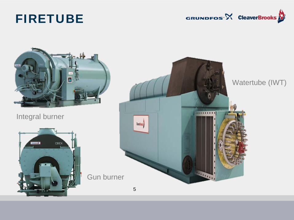
FIRETUBE
Watertube (IWT)
Integral burner
Gun burner5
HORIZONTAL FIRETUBE BOILERSThe Dryback
Refractory Filled Door 1 2
3
4
Baffles
Tubesheet
Two (2) Tubesheets6
WATERTUBE OR IWT
7
THE WATERTUBE BOILER
bull Opposite of Firetubebull Water in the Tubesbull Natural and Forced Circulationbull Large Furnacebull Upper amp Lower Drums orbull Headers
Upper Steam Drum
Lower Mud Drum
Furnace
Outlet nozzle location
8
FLUE GAS SEALING
100 Membrane Construction
Tangent Tube Furnace Design Also Available
9
CONDENSATE IS LIQUID GOLD
A finite resource
10
TYPICAL STEAM SYSTEM
T
T
T
T
T
LegendSteamCond
Vapor
H P Cond Return
D A TankD A Tank
Feed PumpBoiler
Strainer
Trap Trap
TrapTT
TT
DA Tank
TT
TT
TTT
Legend
Trap
HP SteamPRV
LP Steam
Trap
LP Condensate Return
MotiveForce
FlashCondensate tank amp Pump system
11
CONDENSATE RETURN PUMPS
12
FLASH STEAM
T
T
T
T
T
H P Condensate Return
Cond Pump
D A TankD A Tank
Feed PumpBoiler
Strainer
Trap Trap
Trap TrapTT
TT
TT
TT
TTT
HP SteamPRV 15 psig
250 FLP Steam
150 psig366 F
TrapMotiveForce
Feed Tank or DA
13
Flash Tank
Low pressure condensate line
Flash Tank Flash Tank wEconomizer
Use flash steam for heating or deaerating Why not recover the heat from the hot condensate
14
HOT CONDENSATE RETURNED
DeaeratorBoiler Feed System
A vented receiver wastes energy
Pressurized receiver saves energy
Steam diffusing tube
15
Steam
HP Return
Vent
Exhaust OrFlash Steam
ToBoiler
Boiler FeedWater Pump(s)
OverflowDrainer
Cold Make-UpWater
LP Condensate
Make-Up Valve
Check Valve
PRV
Level control
16
SPRAY DEAERATOR
Spray cone
17
TRAY DEAERATOR
steam
Trays
18
PACKED COLUMN DA
19
BOILER FEED WATER TANKSSpray DA Tray DA Column DA
Vented Receiver
20
T
T
T
T
TH P Condensate Return
Cond Pump D A TankD A Tank
Feed PumpBoiler
Strainer
Trap Trap
TrapTrapTT
TT
TT
TT
TTT
HP SteamPRV 15 psig
250 F
LP Steam150 psig366 F
TrapMotiveForce
Feed Tank or DA
HP CONDENSATE RECOVERY
21
HIGH PRESSURE CONDENSATE RECEIVER
bull Takes high pressure condensate directly from the user
bull No need to deaeratebull Pump directly into boilerbull Feed the HPR from the DA
22
BOILER FEED WATER TANK OPTIONSSpray DA Tray DA Column DA
Vented Receiver
HPCR
23
FEED WATER SYSTEMSFor multiple boiler Installations
24
METHOD 1 ndashDirect feed for multiple boilers
Deaerator
Boiler A
Boiler AControlle
r4-20mA signal directly to
Grundfos E-pump instead of
control valve
Boiler BBoiler BControlle
r4-20mA signal directly to
Grundfos E-pump instead of
control valve
25
METHOD 2 ndashBooster sets for multiple boilers
Deaerator Pressure sensor
Bypass
Multiple pump
controller
26
STEAM BOILER PUMP APPLICATIONS AND TYPESBoiler feed pumpsCollection tank pumpsWater treatment pumpsCondensate return pumpsDeaerator tank recycle pumpsDeaerator vacuum pumps (vacuum deaerator tanks only)Economizer pumps
27
SIZING COMPLEXITY FOR BOILER FEED PUMPS
28
BASE FLOW RATE CALCULATION
Base flow = Boiler maximum capacity horsepower X 0069 X C
bull C = 15 for OnOff intermittent operation
bull C = 115 for continuous feed operation
29
ADD FOR CONTINUOUS BOILER BLOWDOWN FLOW
To the Base flow we MIGHT add if specified
For Continuous Boiler Blowdown flowbull Approximately 5 to10 of the pumprsquos flow
rate at the Best Efficiency Point
30
ADD FOR BYPASS RECIRCULATION FLOWCertain feed system control modes require the use of a bypass line back to the source tank ndash such as back to the deaerator tank
Method
NamePump Speed
TypeDuty
Is orifice flow by-pass line
required1 OnOff control and fixed speed pumps Fixed Intermittent No2 Feed control valve and fixed speed pumps Fixed Continuous Yes3 Feed control valve and variable speed pumps Variable Continuous Yes4 Variable speed pumps only (no control valve) Variable Continuous No
31
RECIRCULATION FLOW
bull The solid curve below shows the minimum flow rate as a percentage of the nominal flow rate in relation to the liquid temperature
bull Ignore the dotted line which indicates a pump with special high-temperature construction
32
CALCULATING REQUIRED FEED PUMP HEAD
+ Suction side head+ Discharge side head= Total Dynamic Head
Elevation of DA tank
Elevation of boiler
33
FEED VALVE IMPACTS PUMPING HEAD CALCULATION
34
CALCULATING THE HEADFOR THE FEED PUMP1) At the duty point flow rateHead in feet = Boiler operating pressure X 231 X 103 divide Liquid Specific Gravity
Example Head = 130 psi X 231 X 103 divide 0953 = 324 feet
2) At shutoff head (dead head)Head in feet = Pressure relief valve setting X 231 X 103 divide Liquid Specific Gravity
Example Head = 160 psi X 231 X 103 divide 0953 = 400 feet
35
NPSH ndashFORMULA FOR CALCULATION
NPSHr is obtained from the pump curve
Add two to four feet of safety factor to the NPSHr stated on the curve
NPSHa is calculated
+ Absolute pressure in deaerator tank
plusmn Elevation of minimum water level in tank above feed pump
- Vapor pressure of water in deaerator tank
- Suction line friction loss
= Net Positive Suction Head Available
To avoid cavitation NPSHa must be greater than NPSHr
36
NPSH AND ELEVATIONDeaerator
tank
Boiler feed
pumps
Minimum water level in DA tank
Location of eye of lowest impeller
Difference in elevation
37
NPSH AND SUCTION LINE CONSIDERATIONS
Critical suction line considerations here
38
Check list for boiler feed pump selection
Step Action
1 Determine cont rol method to be used
2 Calculate BASE flow rate
3 Add for Cont inuous Boiler Blowdown flow
4 Add for by-pass flow if required
5 Sum of base flow by-pass flow and Blowdown flow is the total flow required
6 Calculate BASE pumping head
7 Add for all suct ion piping head components
8 Add for all discharge piping system head components (including feed valve if required)
9 Sum of all head components = total pumping head
10 Calculate head at boiler safety vavle set t ing plus three percent
11 Determine deaerator tank water temperature
12 Perform NPSHa calculat ion
13 Make preliminary pump select ion
14 Assure that shutoff head equals or exceeds three percent above safety valve set t ing
15 Check NPSHr versus NPSHa
16 Assure material compat ibilit y - chemical and temperature
17 Make final pump select ion
39
BOILER FEED PUMPS USEFUL FORMULAS
40
SPECIFICATION FOR EXERCISEa) Control Method Continuous duty fixed speed pump with bypass line and feed valveb) Boiler maximum capacity = 250 HPc) Boiler safety valve setting = 125 psigd) Pressure safety factor = 3 above boilerrsquos safety valve settinge) Boiler operating pressure = 100 psigf) Continuous Boiler Blowdown flow - Requiredg) Bypass recirculation flow ndash Requiredh) Altitude ndash Sea leveli) Pressure in deaerator tank above atmospheric pressure = 5 psi (147 + 5 = 197 psi absolute)j) Height of deaerator tank minimum water level above pumprsquos first impeller = 10 feetk) Friction line loss through suction piping = 5 footl) Friction loss through suction side fittings = 5 footm) Friction loss through suction side valves = Nonen) Friction loss through suction side strainer = 1 feeto) Friction loss through discharge piping = 1 footp) Friction loss through discharge side fittings = 1 footq) Pressure drop across feed valve ndash 15 psir) Elevation of boiler maximum water level above pumprsquos discharge port = 5 feets) Liquid Specific Gravity = 0953t) Temperature of water in deaerator tank = 227 degrees Fu) Vapor pressure in deaerator tank = 197 psiv) Pump materials all 316 stainless steel to resist treatment chemicalsw) Mechanical seal to be silicon carbidesilicon carbideEPDM to withstand liquid temperature
41
Feed pumps
CONTROL METHOD
Fixed speed pumps with feed valve and recirculation line
Recirc line
Feed valve
42
STEP 1 ndashDetermine control methodFeed valve controlled system with a continuous duty fixed speed pump has been specified
XStep Action
1 Determine cont rol method to be used
2 Calculate BASE flow rate
3 Add for Cont inuous Boiler Blowdown flow
4 Add for by-pass flow if required
5 Sum of base flow by-pass flow and Blowdown flow is the total flow required
6 Calculate BASE pumping head
7 Add for all suct ion piping head components
8 Add for all discharge piping system head components (including feed valve if required)
9 Sum of all head components = total pumping head
10 Calculate head at boiler safety vavle set t ing plus three percent
11 Determine deaerator tank water temperature
12 Perform NPSHa calculat ion
13 Make preliminary pump select ion
14 Assure that shutoff head equals or exceeds three percent above safety valve set t ing
15 Check NPSHr versus NPSHa
16 Assure material compat ibilit y - chemical and temperature
17 Make final pump select ion
43
STEP 2 ndashCalculate the BASE feed pump flow rate
The formula for this calculation is
bull Boiler maximum capacity in horsepower X 0069 X C
bull The maximum capacity in boiler horsepower is 250
bull The C factor is 115 for continuous duty
Therefore
250 X 0069 X 115 = 20 gpm = BASE flow rate
44
STEP 3 ndashContinuous Boiler Blowdown Flow
Determination
1 The BASE flow rate has been established at 20 gpm
2 We will on next slide need to add for bypass flow which can add 10 to 20 percent to the BASE flow rate
3 Blowdown flow is to be approximately 10 percent of flow at pumprsquos Best Efficiency Point
4 So the total boiler blowdown flow required is approximately 3 gpm
45
STEP 4 ndashAdd for by-pass flow
bull Control is via feed valve with fixed speed pump and for continuous dutybull A bypass will be required
bull Solid curve to right shows minimum flow rate as a percentage of nominal flow rate in relation to liquid temperature
bull Ignore dotted line which indicates a pump with special high-temperature construction
bull At 227degF we require a bypass flow that is about 20 of BEP flow
bull Presuming we can find a pump with BEP at about 25 or so gpm the bypass flow must be about 5 gpm
46
STEP 5 ndashCalculate total flow requiredbull BASE flow = 20 gpmbull Blowdown flow = 3 gpmbull Recirculation flow = 5 gpmbull Total flow required = 28 gpm
XXXX
X
Step Action
1 Determine cont rol method to be used
2 Calculate BASE flow rate
3 Add for Cont inuous Boiler Blowdown flow
4 Add for by-pass flow if required
5 Sum of base flow by-pass flow and Blowdown flow is the total flow required
6 Calculate BASE pumping head
7 Add for all suct ion piping head components
8 Add for all discharge piping system head components (including feed valve if required)
9 Sum of all head components = total pumping head
10 Calculate head at boiler safety vavle set t ing plus three percent
11 Determine deaerator tank water temperature
12 Perform NPSHa calculat ion
13 Make preliminary pump select ion
14 Assure that shutoff head equals or exceeds three percent above safety valve set t ing
15 Check NPSHr versus NPSHa
16 Assure material compat ibilit y - chemical and temperature
17 Make final pump select ion
47
STEP 6 ndashCalculate BASE pumping head
Boiler operating pressure setting + 3
Formula BASE head in feet = Boiler operating pressure X 231 X 103 divide Specific Gravity
BASE head = 100 psi X 231 X 103 divide 0953 = 250 feet
48
STEP 7 ndashAdd for suction piping system head components
From specificationAbsolute pressure on deaerator tank = 197 psi X 231 = - 46 feetWater elevation above first impeller = - 10 feetFriction loss through suction piping = + 5 feetFriction loss through suction fittings = + 5 feetFriction loss through suction side valves and strainer = + 1 feet
Total = - 54 feet
49
STEP 8 ndashAdd for discharge piping system head components
From specificationFriction loss through discharge piping = + 1 footFriction loss through discharge fittings = + 1 footFriction loss through feed valve is 15 psi X 231 = + 35 feetElevation of boiler maximum water level above pump = + 5 feet
Total = + 42 feet
50
STEP 9 ndashSum of all head components
BASE head with safety factor = + 250 feetSuction side piping system head = - 54 feetDischarge side piping system head = + 42 feet
Total = + 238 feet
51
STEP 10 ndashPressure safety valve considerations At shutoff head (dead head)Head in feet = Pressure relief valve setting X 231 X 103 divide Liquid Specific GravityExample Head = 125 psi X 231 X 103 divide 0953 = 312 feet
XXXXXXXXX
XStep Action
1 Determine cont rol method to be used
2 Calculate BASE flow rate
3 Add for Cont inuous Boiler Blowdown flow
4 Add for by-pass flow if required
5 Sum of base flow by-pass flow and Blowdown flow is the total flow required
6 Calculate BASE pumping head
7 Add for all suct ion piping head components
8 Add for all discharge piping system head components (including feed valve if required)
9 Sum of all head components = total pumping head
10 Calculate head at boiler safety vavle set t ing plus three percent
11 Determine deaerator tank water temperature
12 Perform NPSHa calculat ion
13 Make preliminary pump select ion
14 Assure that shutoff head equals or exceeds three percent above safety valve set t ing
15 Check NPSHr versus NPSHa
16 Assure material compat ibilit y - chemical and temperature
17 Make final pump select ion
52
STEP 11 ndashDetermine deaerator tank water temperature
From specification 227degF
53
STEP 12 ndashNPSHa calculation
NPSHa equation
plusmn Elevation + Absolute pressure ndash Vapor Pressure ndash Suction Line Friction = NPSHa
10 feet + (197 psi X 231) - (197 psi X 231) - 2 feet = NPSHa10 feet + 46 feet - 46 feet - 2 feet = 8 feet NPSHa
54
STEP 13 ndashPreliminary pump selection
Conditions of Service Flow = 28 gpmHead = 238 Feet
Does this 10 stage pump pump meet the required flow and head conditions of service
YES
55
STEP 14 ndashPressure safety valve considerations
56
STEP 15 ndashCheck NPSHa vs NPSHr
Conditions of ServiceFlow = 28gpmHead = 238 FeetNPSHa = 8 Feet
bull Pump meets or exceeds flowhead requirement
bull Low-NPSHr first stage = 4 feet required
bull NPSHr safety factor = 2 to 4 feet
bull Target NPSHr = 8 feetbull NPSHa = 8 feet
Does NPSHa equal or exceed NPSHr
YES57
STEP 15 ndashNPSH - ContinuedConditions of Service Flow = 28 gpm Head = 238 Feet NPSHa = 8 FeetThe NPSHa is equal to or exceeds the NPSHr of 8 feet
XXXXXXXXXX
XXXXX
Step Action
1 Determine cont rol method to be used
2 Calculate BASE flow rate
3 Add for Cont inuous Boiler Blowdown flow
4 Add for by-pass flow if required
5 Sum of base flow by-pass flow and Blowdown flow is the total flow required
6 Calculate BASE pumping head
7 Add for all suct ion piping head components
8 Add for all discharge piping system head components (including feed valve if required)
9 Sum of all head components = total pumping head
10 Calculate head at boiler safety vavle set t ing plus three percent
11 Determine deaerator tank water temperature
12 Perform NPSHa calculat ion
13 Make preliminary pump select ion
14 Assure that shutoff head equals or exceeds three percent above safety valve set t ing
15 Check NPSHr versus NPSHa
16 Assure material compat ibilit y - chemical and temperature
17 Make final pump select ion
58
STEP 16 ndashCheck material compatibility
bull Pump materials 316 stainless steelbull Mechanical seal materials Silicon carbidesilicon
carbideEPDM
59
STEP 17 ndashFinal pump selectionPump meets all specification requirements
XXXXXXXXX
X
XXXXXXX
Step Action
1 Determine cont rol method to be used
2 Calculate BASE flow rate
3 Add for Cont inuous Boiler Blowdown flow
4 Add for by-pass flow if required
5 Sum of base flow by-pass flow and Blowdown flow is the total flow required
6 Calculate BASE pumping head
7 Add for all suct ion piping head components
8 Add for all discharge piping system head components (including feed valve if required)
9 Sum of all head components = total pumping head
10 Calculate head at boiler safety vavle set t ing plus three percent
11 Determine deaerator tank water temperature
12 Perform NPSHa calculat ion
13 Make preliminary pump select ion
14 Assure that shutoff head equals or exceeds three percent above safety valve set t ing
15 Check NPSHr versus NPSHa
16 Assure material compat ibilit y - chemical and temperature
17 Make final pump select ion
60
61
SUMMARYbull Steam condensate is a very valuable commodity which needs to saved and used as much as possiblebull Most commonly used boilers for process are industrial firetubes and watertube boilers IWTsbull High pressure condensate flash steam can be used for various purposes such as unit heaters or the
DAbull Condensate can be returned to vented receivers or pressurized deaerators (Spray Tray amp Column)bull Sometimes high pressure condensate receivers are employed Save considerable lossesbull Boiler feed pump selection involves 17 decision points which need to be carefully consideredbull Calculating the pumprsquos base flow rate differs when the pump operates continuously (15 safety factor)
or onoff (50 safety factor)bull Sometimes the base flow rate needs to include for continuous pump re-circulation and maybe for
continuous blow downbull Total Dynamic Head (TDH) is a that pressure the pump must overcome to get water in the boiler and
includes the positive pressure at the pumprsquos inlet after suction pipe losses and the piping losses through the discharge piping before overcoming the boilerrsquos operating pressure
bull Net Positive Suction Head (NPSH) is the pressure required at the pumprsquos suction to mitigate cavitation
bull NPSHA is the NPSH available after all the friction losses on the suction side have been determined in light of the pumprsquos minimum and maximum flow rates
bull The seal selection for the pump is very important and can vary based on the boilerrsquos operating pressuretemperature chemicals in the feed water etc
62
Gregg Achtenhagengachtenhagencleaverbrookscom
Jim Swetyejswetyegrundfoscom
QUESTIONS
63
Over 25000 Grundfos parts are available through your local Cleaver-Brooks RepresentativeVisit cleaverbrookscomreps for all boiler sales and service
| Step | Action | |||||
| 1 | Determine control method to be used | |||||
| 2 | Calculate BASE flow rate | |||||
| 3 | Add for Continuous Boiler Blowdown flow | |||||
| 4 | Add for by-pass flow if required | |||||
| 5 | Sum of base flow by-pass flow and Blowdown flow is the total flow required | |||||
| 6 | Calculate BASE pumping head | |||||
| 7 | Add for all suction piping head components | |||||
| 8 | Add for all discharge piping system head components (including feed valve if required) | |||||
| 9 | Sum of all head components = total pumping head | |||||
| 10 | Calculate head at boiler safety vavle setting plus three percent | |||||
| 11 | Determine deaerator tank water temperature | |||||
| 12 | Perform NPSHa calculation | |||||
| 13 | Make preliminary pump selection | |||||
| 14 | Assure that shutoff head equals or exceeds three percent above safety valve setting | |||||
| 15 | Check NPSHr versus NPSHa | |||||
| 16 | Assure material compatibility - chemical and temperature | |||||
| 17 | Make final pump selection |
| Step | Action | |||||
| 1 | Determine control method to be used | |||||
| 2 | Calculate BASE flow rate | |||||
| 3 | Add for Continuous Boiler Blowdown flow | |||||
| 4 | Add for by-pass flow if required | |||||
| 5 | Sum of base flow by-pass flow and Blowdown flow is the total flow required | |||||
| 6 | Calculate BASE pumping head | |||||
| 7 | Add for all suction piping head components | |||||
| 8 | Add for all discharge piping system head components (including feed valve if required) | |||||
| 9 | Sum of all head components = total pumping head | |||||
| 10 | Calculate head at boiler safety vavle setting plus three percent | |||||
| 11 | Determine deaerator tank water temperature | |||||
| 12 | Perform NPSHa calculation | |||||
| 13 | Make preliminary pump selection | |||||
| 14 | Assure that shutoff head equals or exceeds three percent above safety valve setting | |||||
| 15 | Check NPSHr versus NPSHa | |||||
| 16 | Assure material compatibility - chemical and temperature | |||||
| 17 | Make final pump selection |
| Step | Action | |||||
| 1 | Determine control method to be used | |||||
| 2 | Calculate BASE flow rate | |||||
| 3 | Add for Continuous Boiler Blowdown flow | |||||
| 4 | Add for by-pass flow if required | |||||
| 5 | Sum of base flow by-pass flow and Blowdown flow is the total flow required | |||||
| 6 | Calculate BASE pumping head | |||||
| 7 | Add for all suction piping head components | |||||
| 8 | Add for all discharge piping system head components (including feed valve if required) | |||||
| 9 | Sum of all head components = total pumping head | |||||
| 10 | Calculate head at boiler safety vavle setting plus three percent | |||||
| 11 | Determine deaerator tank water temperature | |||||
| 12 | Perform NPSHa calculation | |||||
| 13 | Make preliminary pump selection | |||||
| 14 | Assure that shutoff head equals or exceeds three percent above safety valve setting | |||||
| 15 | Check NPSHr versus NPSHa | |||||
| 16 | Assure material compatibility - chemical and temperature | |||||
| 17 | Make final pump selection |
| Step | Action | |||||
| 1 | Determine control method to be used | |||||
| 2 | Calculate BASE flow rate | |||||
| 3 | Add for Continuous Boiler Blowdown flow | |||||
| 4 | Add for by-pass flow if required | |||||
| 5 | Sum of base flow by-pass flow and Blowdown flow is the total flow required | |||||
| 6 | Calculate BASE pumping head | |||||
| 7 | Add for all suction piping head components | |||||
| 8 | Add for all discharge piping system head components (including feed valve if required) | |||||
| 9 | Sum of all head components = total pumping head | |||||
| 10 | Calculate head at boiler safety vavle setting plus three percent | |||||
| 11 | Determine deaerator tank water temperature | |||||
| 12 | Perform NPSHa calculation | |||||
| 13 | Make preliminary pump selection | |||||
| 14 | Assure that shutoff head equals or exceeds three percent above safety valve setting | |||||
| 15 | Check NPSHr versus NPSHa | |||||
| 16 | Assure material compatibility - chemical and temperature | |||||
| 17 | Make final pump selection |
| Step | Action | |||||
| 1 | Determine control method to be used | |||||
| 2 | Calculate BASE flow rate | |||||
| 3 | Add for Continuous Boiler Blowdown flow | |||||
| 4 | Add for by-pass flow if required | |||||
| 5 | Sum of base flow by-pass flow and Blowdown flow is the total flow required | |||||
| 6 | Calculate BASE pumping head | |||||
| 7 | Add for all suction piping head components | |||||
| 8 | Add for all discharge piping system head components (including feed valve if required) | |||||
| 9 | Sum of all head components = total pumping head | |||||
| 10 | Calculate head at boiler safety vavle setting plus three percent | |||||
| 11 | Determine deaerator tank water temperature | |||||
| 12 | Perform NPSHa calculation | |||||
| 13 | Make preliminary pump selection | |||||
| 14 | Assure that shutoff head equals or exceeds three percent above safety valve setting | |||||
| 15 | Check NPSHr versus NPSHa | |||||
| 16 | Assure material compatibility - chemical and temperature | |||||
| 17 | Make final pump selection |
| 1 Base flow calculation equation | |||||
| Boiler maximum capacity horsepower X 0069 X C = Base flow rate | |||||
| C = 150 for OnOff intermittent operation | |||||
| C = 115 for continuous feed operation | |||||
| 2 Determine BASE head for feed pump | |||||
| Formula based on Safety Valve setting | |||||
| Pump head in feet = Maximum pressure X 231 X 103 divide Liquid Specific Gravity | |||||
| 3 Head components on suction side of piping system | |||||
| Pressure above atmospheric on deaerator converted to feet of head = | feet | ||||
| Elevation difference between minimum deaerator water level and pump inlet = | feet | ||||
| Suction pipe friction loss = | feet | ||||
| Suction fitting friction loss = | feet | ||||
| Suction line valves and strainer friction loss = | feet | ||||
| Total = | feet | ||||
| 4 Head components on discharge side of piping system | |||||
| Friction loss through discharge piping = | feet | ||||
| Friction loss through discharge fittings = | feet | ||||
| Friction loss through feed valve = | feet | ||||
| Elevation of boiler maximum water level above pump = | feet | ||||
| Total = | feet | ||||
| 5 NPSHa equation | |||||
| plusmn Elevation + Absolute pressure ndash Vapor Pressure ndash Suction Line Friction = NPSHa | |||||
| (Feet) (psi X 231 = Feet) (psi X 231 = Feet) (Feet) (Feet) | |||||
| Elevation of deaerator tank minimum water level above pumprsquos first impeller | |||||
| Step | Action | |||||
| 1 | Determine control method to be used | |||||
| 2 | Calculate BASE flow rate | |||||
| 3 | Add for Continuous Boiler Blowdown flow | |||||
| 4 | Add for by-pass flow if required | |||||
| 5 | Sum of base flow by-pass flow and Blowdown flow is the total flow required | |||||
| 6 | Calculate BASE pumping head | |||||
| 7 | Add for all suction piping head components | |||||
| 8 | Add for all discharge piping system head components (including feed valve if required) | |||||
| 9 | Sum of all head components = total pumping head | |||||
| 10 | Calculate head at boiler safety vavle setting plus three percent | |||||
| 11 | Determine deaerator tank water temperature | |||||
| 12 | Perform NPSHa calculation | |||||
| 13 | Make preliminary pump selection | |||||
| 14 | Assure that shutoff head equals or exceeds three percent above safety valve setting | |||||
| 15 | Check NPSHr versus NPSHa | |||||
| 16 | Assure material compatibility - chemical and temperature | |||||
| 17 | Make final pump selection |
| Method | Name | Is there head loss across feed valve | Typical psi loss across feed valve | Typical feed water temperature | Typical Specific Gravity | Conversion formula | Typical feet of head loss across feed valve | Pump Speed Type | Duty | Is orifce flow by-pass line required | Orifice flow rate | |||||||||||||
| 1 | On Off control and fixed speed pumps | Yes | 30 | 225degF | 0954 | psi X 231 divide Sp Grv = feet | 726 | Fixed | Intermittent | No | Not applicable | |||||||||||||
| 2 | Feed control valve and fixed speed pumps | Yes | 30 | 225degF | 0954 | psi X 231 divide Sp Grv = feet | 726 | Fixed | Continuous | Yes | 20 of nominal | |||||||||||||
| 3 | Feed control valve and variable speed pumps | Yes | 30 | 225degF | 0954 | psi X 231 divide Sp Grv = feet | 726 | Variable | Continuous | Yes | 20 of nominal | |||||||||||||
| 4 | Variable speed pumps only (no control valve) | No | None | 225degF | 0954 | Not applicable | Not applicable | Variable | Continuous | No | Not applicable | |||||||||||||
| Orifice flow rate varies by manufacturers Will use 20 for these exercises | ||||||||||||||||||||||||
| Must add for all head factors on suction and discharge sides of pump | ||||||||||||||||||||||||
| Method | Name | Pump Speed Type | Duty | Is orifice flow by-pass line required | ||||||||||||||||||||
| 1 | OnOff control and fixed speed pumps | Fixed | Intermittent | No | ||||||||||||||||||||
| 2 | Feed control valve and fixed speed pumps | Fixed | Continuous | Yes | ||||||||||||||||||||
| 3 | Feed control valve and variable speed pumps | Variable | Continuous | Yes | ||||||||||||||||||||
| 4 | Variable speed pumps only (no control valve) | Variable | Continuous | No |
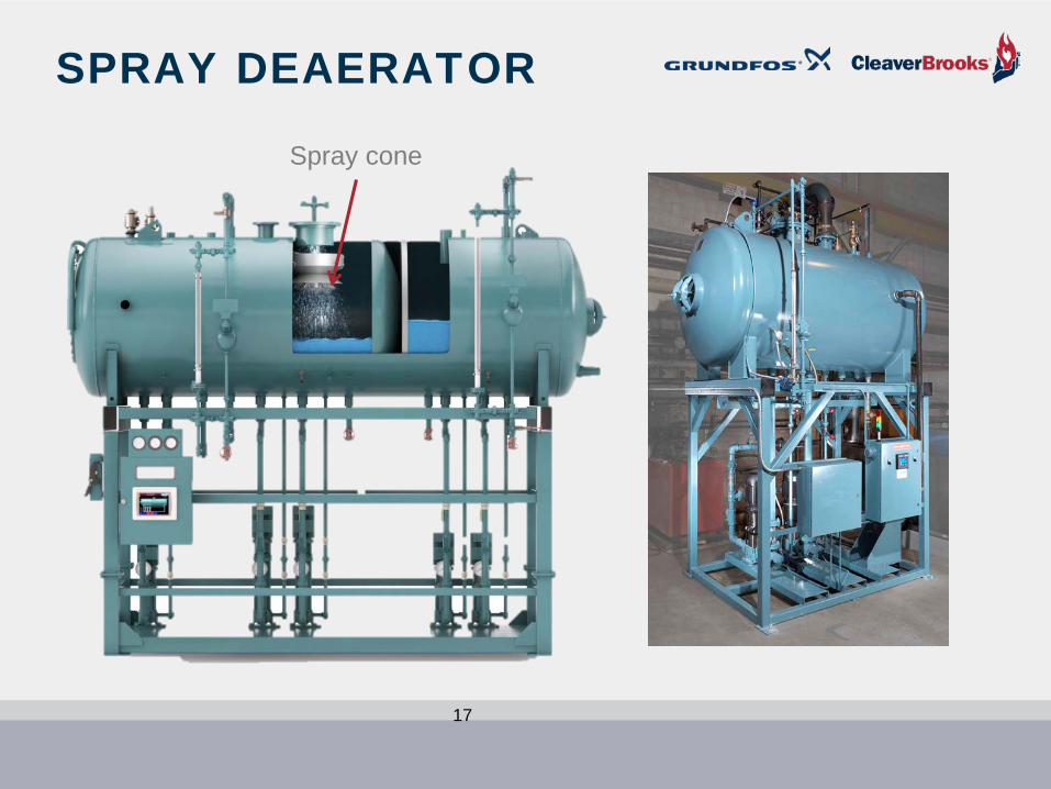
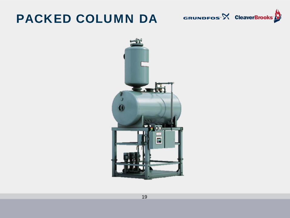

T
T
T
T
TH P Condensate Return
Cond Pump D A TankD A Tank
Feed PumpBoiler
Strainer
Trap Trap
TrapTrapTT
TT
TT
TT
TTT
HP SteamPRV 15 psig
250 F
LP Steam150 psig366 F
TrapMotiveForce
Feed Tank or DA
HP CONDENSATE RECOVERY
21
HIGH PRESSURE CONDENSATE RECEIVER
bull Takes high pressure condensate directly from the user
bull No need to deaeratebull Pump directly into boilerbull Feed the HPR from the DA
22
BOILER FEED WATER TANK OPTIONSSpray DA Tray DA Column DA
Vented Receiver
HPCR
23
FEED WATER SYSTEMSFor multiple boiler Installations
24
METHOD 1 ndashDirect feed for multiple boilers
Deaerator
Boiler A
Boiler AControlle
r4-20mA signal directly to
Grundfos E-pump instead of
control valve
Boiler BBoiler BControlle
r4-20mA signal directly to
Grundfos E-pump instead of
control valve
25
METHOD 2 ndashBooster sets for multiple boilers
Deaerator Pressure sensor
Bypass
Multiple pump
controller
26
STEAM BOILER PUMP APPLICATIONS AND TYPESBoiler feed pumpsCollection tank pumpsWater treatment pumpsCondensate return pumpsDeaerator tank recycle pumpsDeaerator vacuum pumps (vacuum deaerator tanks only)Economizer pumps
27
SIZING COMPLEXITY FOR BOILER FEED PUMPS
28
BASE FLOW RATE CALCULATION
Base flow = Boiler maximum capacity horsepower X 0069 X C
bull C = 15 for OnOff intermittent operation
bull C = 115 for continuous feed operation
29
ADD FOR CONTINUOUS BOILER BLOWDOWN FLOW
To the Base flow we MIGHT add if specified
For Continuous Boiler Blowdown flowbull Approximately 5 to10 of the pumprsquos flow
rate at the Best Efficiency Point
30
ADD FOR BYPASS RECIRCULATION FLOWCertain feed system control modes require the use of a bypass line back to the source tank ndash such as back to the deaerator tank
Method
NamePump Speed
TypeDuty
Is orifice flow by-pass line
required1 OnOff control and fixed speed pumps Fixed Intermittent No2 Feed control valve and fixed speed pumps Fixed Continuous Yes3 Feed control valve and variable speed pumps Variable Continuous Yes4 Variable speed pumps only (no control valve) Variable Continuous No
31
RECIRCULATION FLOW
bull The solid curve below shows the minimum flow rate as a percentage of the nominal flow rate in relation to the liquid temperature
bull Ignore the dotted line which indicates a pump with special high-temperature construction
32
CALCULATING REQUIRED FEED PUMP HEAD
+ Suction side head+ Discharge side head= Total Dynamic Head
Elevation of DA tank
Elevation of boiler
33
FEED VALVE IMPACTS PUMPING HEAD CALCULATION
34
CALCULATING THE HEADFOR THE FEED PUMP1) At the duty point flow rateHead in feet = Boiler operating pressure X 231 X 103 divide Liquid Specific Gravity
Example Head = 130 psi X 231 X 103 divide 0953 = 324 feet
2) At shutoff head (dead head)Head in feet = Pressure relief valve setting X 231 X 103 divide Liquid Specific Gravity
Example Head = 160 psi X 231 X 103 divide 0953 = 400 feet
35
NPSH ndashFORMULA FOR CALCULATION
NPSHr is obtained from the pump curve
Add two to four feet of safety factor to the NPSHr stated on the curve
NPSHa is calculated
+ Absolute pressure in deaerator tank
plusmn Elevation of minimum water level in tank above feed pump
- Vapor pressure of water in deaerator tank
- Suction line friction loss
= Net Positive Suction Head Available
To avoid cavitation NPSHa must be greater than NPSHr
36
NPSH AND ELEVATIONDeaerator
tank
Boiler feed
pumps
Minimum water level in DA tank
Location of eye of lowest impeller
Difference in elevation
37
NPSH AND SUCTION LINE CONSIDERATIONS
Critical suction line considerations here
38
Check list for boiler feed pump selection
Step Action
1 Determine cont rol method to be used
2 Calculate BASE flow rate
3 Add for Cont inuous Boiler Blowdown flow
4 Add for by-pass flow if required
5 Sum of base flow by-pass flow and Blowdown flow is the total flow required
6 Calculate BASE pumping head
7 Add for all suct ion piping head components
8 Add for all discharge piping system head components (including feed valve if required)
9 Sum of all head components = total pumping head
10 Calculate head at boiler safety vavle set t ing plus three percent
11 Determine deaerator tank water temperature
12 Perform NPSHa calculat ion
13 Make preliminary pump select ion
14 Assure that shutoff head equals or exceeds three percent above safety valve set t ing
15 Check NPSHr versus NPSHa
16 Assure material compat ibilit y - chemical and temperature
17 Make final pump select ion
39
BOILER FEED PUMPS USEFUL FORMULAS
40
SPECIFICATION FOR EXERCISEa) Control Method Continuous duty fixed speed pump with bypass line and feed valveb) Boiler maximum capacity = 250 HPc) Boiler safety valve setting = 125 psigd) Pressure safety factor = 3 above boilerrsquos safety valve settinge) Boiler operating pressure = 100 psigf) Continuous Boiler Blowdown flow - Requiredg) Bypass recirculation flow ndash Requiredh) Altitude ndash Sea leveli) Pressure in deaerator tank above atmospheric pressure = 5 psi (147 + 5 = 197 psi absolute)j) Height of deaerator tank minimum water level above pumprsquos first impeller = 10 feetk) Friction line loss through suction piping = 5 footl) Friction loss through suction side fittings = 5 footm) Friction loss through suction side valves = Nonen) Friction loss through suction side strainer = 1 feeto) Friction loss through discharge piping = 1 footp) Friction loss through discharge side fittings = 1 footq) Pressure drop across feed valve ndash 15 psir) Elevation of boiler maximum water level above pumprsquos discharge port = 5 feets) Liquid Specific Gravity = 0953t) Temperature of water in deaerator tank = 227 degrees Fu) Vapor pressure in deaerator tank = 197 psiv) Pump materials all 316 stainless steel to resist treatment chemicalsw) Mechanical seal to be silicon carbidesilicon carbideEPDM to withstand liquid temperature
41
Feed pumps
CONTROL METHOD
Fixed speed pumps with feed valve and recirculation line
Recirc line
Feed valve
42
STEP 1 ndashDetermine control methodFeed valve controlled system with a continuous duty fixed speed pump has been specified
XStep Action
1 Determine cont rol method to be used
2 Calculate BASE flow rate
3 Add for Cont inuous Boiler Blowdown flow
4 Add for by-pass flow if required
5 Sum of base flow by-pass flow and Blowdown flow is the total flow required
6 Calculate BASE pumping head
7 Add for all suct ion piping head components
8 Add for all discharge piping system head components (including feed valve if required)
9 Sum of all head components = total pumping head
10 Calculate head at boiler safety vavle set t ing plus three percent
11 Determine deaerator tank water temperature
12 Perform NPSHa calculat ion
13 Make preliminary pump select ion
14 Assure that shutoff head equals or exceeds three percent above safety valve set t ing
15 Check NPSHr versus NPSHa
16 Assure material compat ibilit y - chemical and temperature
17 Make final pump select ion
43
STEP 2 ndashCalculate the BASE feed pump flow rate
The formula for this calculation is
bull Boiler maximum capacity in horsepower X 0069 X C
bull The maximum capacity in boiler horsepower is 250
bull The C factor is 115 for continuous duty
Therefore
250 X 0069 X 115 = 20 gpm = BASE flow rate
44
STEP 3 ndashContinuous Boiler Blowdown Flow
Determination
1 The BASE flow rate has been established at 20 gpm
2 We will on next slide need to add for bypass flow which can add 10 to 20 percent to the BASE flow rate
3 Blowdown flow is to be approximately 10 percent of flow at pumprsquos Best Efficiency Point
4 So the total boiler blowdown flow required is approximately 3 gpm
45
STEP 4 ndashAdd for by-pass flow
bull Control is via feed valve with fixed speed pump and for continuous dutybull A bypass will be required
bull Solid curve to right shows minimum flow rate as a percentage of nominal flow rate in relation to liquid temperature
bull Ignore dotted line which indicates a pump with special high-temperature construction
bull At 227degF we require a bypass flow that is about 20 of BEP flow
bull Presuming we can find a pump with BEP at about 25 or so gpm the bypass flow must be about 5 gpm
46
STEP 5 ndashCalculate total flow requiredbull BASE flow = 20 gpmbull Blowdown flow = 3 gpmbull Recirculation flow = 5 gpmbull Total flow required = 28 gpm
XXXX
X
Step Action
1 Determine cont rol method to be used
2 Calculate BASE flow rate
3 Add for Cont inuous Boiler Blowdown flow
4 Add for by-pass flow if required
5 Sum of base flow by-pass flow and Blowdown flow is the total flow required
6 Calculate BASE pumping head
7 Add for all suct ion piping head components
8 Add for all discharge piping system head components (including feed valve if required)
9 Sum of all head components = total pumping head
10 Calculate head at boiler safety vavle set t ing plus three percent
11 Determine deaerator tank water temperature
12 Perform NPSHa calculat ion
13 Make preliminary pump select ion
14 Assure that shutoff head equals or exceeds three percent above safety valve set t ing
15 Check NPSHr versus NPSHa
16 Assure material compat ibilit y - chemical and temperature
17 Make final pump select ion
47
STEP 6 ndashCalculate BASE pumping head
Boiler operating pressure setting + 3
Formula BASE head in feet = Boiler operating pressure X 231 X 103 divide Specific Gravity
BASE head = 100 psi X 231 X 103 divide 0953 = 250 feet
48
STEP 7 ndashAdd for suction piping system head components
From specificationAbsolute pressure on deaerator tank = 197 psi X 231 = - 46 feetWater elevation above first impeller = - 10 feetFriction loss through suction piping = + 5 feetFriction loss through suction fittings = + 5 feetFriction loss through suction side valves and strainer = + 1 feet
Total = - 54 feet
49
STEP 8 ndashAdd for discharge piping system head components
From specificationFriction loss through discharge piping = + 1 footFriction loss through discharge fittings = + 1 footFriction loss through feed valve is 15 psi X 231 = + 35 feetElevation of boiler maximum water level above pump = + 5 feet
Total = + 42 feet
50
STEP 9 ndashSum of all head components
BASE head with safety factor = + 250 feetSuction side piping system head = - 54 feetDischarge side piping system head = + 42 feet
Total = + 238 feet
51
STEP 10 ndashPressure safety valve considerations At shutoff head (dead head)Head in feet = Pressure relief valve setting X 231 X 103 divide Liquid Specific GravityExample Head = 125 psi X 231 X 103 divide 0953 = 312 feet
XXXXXXXXX
XStep Action
1 Determine cont rol method to be used
2 Calculate BASE flow rate
3 Add for Cont inuous Boiler Blowdown flow
4 Add for by-pass flow if required
5 Sum of base flow by-pass flow and Blowdown flow is the total flow required
6 Calculate BASE pumping head
7 Add for all suct ion piping head components
8 Add for all discharge piping system head components (including feed valve if required)
9 Sum of all head components = total pumping head
10 Calculate head at boiler safety vavle set t ing plus three percent
11 Determine deaerator tank water temperature
12 Perform NPSHa calculat ion
13 Make preliminary pump select ion
14 Assure that shutoff head equals or exceeds three percent above safety valve set t ing
15 Check NPSHr versus NPSHa
16 Assure material compat ibilit y - chemical and temperature
17 Make final pump select ion
52
STEP 11 ndashDetermine deaerator tank water temperature
From specification 227degF
53
STEP 12 ndashNPSHa calculation
NPSHa equation
plusmn Elevation + Absolute pressure ndash Vapor Pressure ndash Suction Line Friction = NPSHa
10 feet + (197 psi X 231) - (197 psi X 231) - 2 feet = NPSHa10 feet + 46 feet - 46 feet - 2 feet = 8 feet NPSHa
54
STEP 13 ndashPreliminary pump selection
Conditions of Service Flow = 28 gpmHead = 238 Feet
Does this 10 stage pump pump meet the required flow and head conditions of service
YES
55
STEP 14 ndashPressure safety valve considerations
56
STEP 15 ndashCheck NPSHa vs NPSHr
Conditions of ServiceFlow = 28gpmHead = 238 FeetNPSHa = 8 Feet
bull Pump meets or exceeds flowhead requirement
bull Low-NPSHr first stage = 4 feet required
bull NPSHr safety factor = 2 to 4 feet
bull Target NPSHr = 8 feetbull NPSHa = 8 feet
Does NPSHa equal or exceed NPSHr
YES57
STEP 15 ndashNPSH - ContinuedConditions of Service Flow = 28 gpm Head = 238 Feet NPSHa = 8 FeetThe NPSHa is equal to or exceeds the NPSHr of 8 feet
XXXXXXXXXX
XXXXX
Step Action
1 Determine cont rol method to be used
2 Calculate BASE flow rate
3 Add for Cont inuous Boiler Blowdown flow
4 Add for by-pass flow if required
5 Sum of base flow by-pass flow and Blowdown flow is the total flow required
6 Calculate BASE pumping head
7 Add for all suct ion piping head components
8 Add for all discharge piping system head components (including feed valve if required)
9 Sum of all head components = total pumping head
10 Calculate head at boiler safety vavle set t ing plus three percent
11 Determine deaerator tank water temperature
12 Perform NPSHa calculat ion
13 Make preliminary pump select ion
14 Assure that shutoff head equals or exceeds three percent above safety valve set t ing
15 Check NPSHr versus NPSHa
16 Assure material compat ibilit y - chemical and temperature
17 Make final pump select ion
58
STEP 16 ndashCheck material compatibility
bull Pump materials 316 stainless steelbull Mechanical seal materials Silicon carbidesilicon
carbideEPDM
59
STEP 17 ndashFinal pump selectionPump meets all specification requirements
XXXXXXXXX
X
XXXXXXX
Step Action
1 Determine cont rol method to be used
2 Calculate BASE flow rate
3 Add for Cont inuous Boiler Blowdown flow
4 Add for by-pass flow if required
5 Sum of base flow by-pass flow and Blowdown flow is the total flow required
6 Calculate BASE pumping head
7 Add for all suct ion piping head components
8 Add for all discharge piping system head components (including feed valve if required)
9 Sum of all head components = total pumping head
10 Calculate head at boiler safety vavle set t ing plus three percent
11 Determine deaerator tank water temperature
12 Perform NPSHa calculat ion
13 Make preliminary pump select ion
14 Assure that shutoff head equals or exceeds three percent above safety valve set t ing
15 Check NPSHr versus NPSHa
16 Assure material compat ibilit y - chemical and temperature
17 Make final pump select ion
60
61
SUMMARYbull Steam condensate is a very valuable commodity which needs to saved and used as much as possiblebull Most commonly used boilers for process are industrial firetubes and watertube boilers IWTsbull High pressure condensate flash steam can be used for various purposes such as unit heaters or the
DAbull Condensate can be returned to vented receivers or pressurized deaerators (Spray Tray amp Column)bull Sometimes high pressure condensate receivers are employed Save considerable lossesbull Boiler feed pump selection involves 17 decision points which need to be carefully consideredbull Calculating the pumprsquos base flow rate differs when the pump operates continuously (15 safety factor)
or onoff (50 safety factor)bull Sometimes the base flow rate needs to include for continuous pump re-circulation and maybe for
continuous blow downbull Total Dynamic Head (TDH) is a that pressure the pump must overcome to get water in the boiler and
includes the positive pressure at the pumprsquos inlet after suction pipe losses and the piping losses through the discharge piping before overcoming the boilerrsquos operating pressure
bull Net Positive Suction Head (NPSH) is the pressure required at the pumprsquos suction to mitigate cavitation
bull NPSHA is the NPSH available after all the friction losses on the suction side have been determined in light of the pumprsquos minimum and maximum flow rates
bull The seal selection for the pump is very important and can vary based on the boilerrsquos operating pressuretemperature chemicals in the feed water etc
62
Gregg Achtenhagengachtenhagencleaverbrookscom
Jim Swetyejswetyegrundfoscom
QUESTIONS
63
Over 25000 Grundfos parts are available through your local Cleaver-Brooks RepresentativeVisit cleaverbrookscomreps for all boiler sales and service
| Step | Action | |||||
| 1 | Determine control method to be used | |||||
| 2 | Calculate BASE flow rate | |||||
| 3 | Add for Continuous Boiler Blowdown flow | |||||
| 4 | Add for by-pass flow if required | |||||
| 5 | Sum of base flow by-pass flow and Blowdown flow is the total flow required | |||||
| 6 | Calculate BASE pumping head | |||||
| 7 | Add for all suction piping head components | |||||
| 8 | Add for all discharge piping system head components (including feed valve if required) | |||||
| 9 | Sum of all head components = total pumping head | |||||
| 10 | Calculate head at boiler safety vavle setting plus three percent | |||||
| 11 | Determine deaerator tank water temperature | |||||
| 12 | Perform NPSHa calculation | |||||
| 13 | Make preliminary pump selection | |||||
| 14 | Assure that shutoff head equals or exceeds three percent above safety valve setting | |||||
| 15 | Check NPSHr versus NPSHa | |||||
| 16 | Assure material compatibility - chemical and temperature | |||||
| 17 | Make final pump selection |
| Step | Action | |||||
| 1 | Determine control method to be used | |||||
| 2 | Calculate BASE flow rate | |||||
| 3 | Add for Continuous Boiler Blowdown flow | |||||
| 4 | Add for by-pass flow if required | |||||
| 5 | Sum of base flow by-pass flow and Blowdown flow is the total flow required | |||||
| 6 | Calculate BASE pumping head | |||||
| 7 | Add for all suction piping head components | |||||
| 8 | Add for all discharge piping system head components (including feed valve if required) | |||||
| 9 | Sum of all head components = total pumping head | |||||
| 10 | Calculate head at boiler safety vavle setting plus three percent | |||||
| 11 | Determine deaerator tank water temperature | |||||
| 12 | Perform NPSHa calculation | |||||
| 13 | Make preliminary pump selection | |||||
| 14 | Assure that shutoff head equals or exceeds three percent above safety valve setting | |||||
| 15 | Check NPSHr versus NPSHa | |||||
| 16 | Assure material compatibility - chemical and temperature | |||||
| 17 | Make final pump selection |
| Step | Action | |||||
| 1 | Determine control method to be used | |||||
| 2 | Calculate BASE flow rate | |||||
| 3 | Add for Continuous Boiler Blowdown flow | |||||
| 4 | Add for by-pass flow if required | |||||
| 5 | Sum of base flow by-pass flow and Blowdown flow is the total flow required | |||||
| 6 | Calculate BASE pumping head | |||||
| 7 | Add for all suction piping head components | |||||
| 8 | Add for all discharge piping system head components (including feed valve if required) | |||||
| 9 | Sum of all head components = total pumping head | |||||
| 10 | Calculate head at boiler safety vavle setting plus three percent | |||||
| 11 | Determine deaerator tank water temperature | |||||
| 12 | Perform NPSHa calculation | |||||
| 13 | Make preliminary pump selection | |||||
| 14 | Assure that shutoff head equals or exceeds three percent above safety valve setting | |||||
| 15 | Check NPSHr versus NPSHa | |||||
| 16 | Assure material compatibility - chemical and temperature | |||||
| 17 | Make final pump selection |
| Step | Action | |||||
| 1 | Determine control method to be used | |||||
| 2 | Calculate BASE flow rate | |||||
| 3 | Add for Continuous Boiler Blowdown flow | |||||
| 4 | Add for by-pass flow if required | |||||
| 5 | Sum of base flow by-pass flow and Blowdown flow is the total flow required | |||||
| 6 | Calculate BASE pumping head | |||||
| 7 | Add for all suction piping head components | |||||
| 8 | Add for all discharge piping system head components (including feed valve if required) | |||||
| 9 | Sum of all head components = total pumping head | |||||
| 10 | Calculate head at boiler safety vavle setting plus three percent | |||||
| 11 | Determine deaerator tank water temperature | |||||
| 12 | Perform NPSHa calculation | |||||
| 13 | Make preliminary pump selection | |||||
| 14 | Assure that shutoff head equals or exceeds three percent above safety valve setting | |||||
| 15 | Check NPSHr versus NPSHa | |||||
| 16 | Assure material compatibility - chemical and temperature | |||||
| 17 | Make final pump selection |
| Step | Action | |||||
| 1 | Determine control method to be used | |||||
| 2 | Calculate BASE flow rate | |||||
| 3 | Add for Continuous Boiler Blowdown flow | |||||
| 4 | Add for by-pass flow if required | |||||
| 5 | Sum of base flow by-pass flow and Blowdown flow is the total flow required | |||||
| 6 | Calculate BASE pumping head | |||||
| 7 | Add for all suction piping head components | |||||
| 8 | Add for all discharge piping system head components (including feed valve if required) | |||||
| 9 | Sum of all head components = total pumping head | |||||
| 10 | Calculate head at boiler safety vavle setting plus three percent | |||||
| 11 | Determine deaerator tank water temperature | |||||
| 12 | Perform NPSHa calculation | |||||
| 13 | Make preliminary pump selection | |||||
| 14 | Assure that shutoff head equals or exceeds three percent above safety valve setting | |||||
| 15 | Check NPSHr versus NPSHa | |||||
| 16 | Assure material compatibility - chemical and temperature | |||||
| 17 | Make final pump selection |
| 1 Base flow calculation equation | |||||
| Boiler maximum capacity horsepower X 0069 X C = Base flow rate | |||||
| C = 150 for OnOff intermittent operation | |||||
| C = 115 for continuous feed operation | |||||
| 2 Determine BASE head for feed pump | |||||
| Formula based on Safety Valve setting | |||||
| Pump head in feet = Maximum pressure X 231 X 103 divide Liquid Specific Gravity | |||||
| 3 Head components on suction side of piping system | |||||
| Pressure above atmospheric on deaerator converted to feet of head = | feet | ||||
| Elevation difference between minimum deaerator water level and pump inlet = | feet | ||||
| Suction pipe friction loss = | feet | ||||
| Suction fitting friction loss = | feet | ||||
| Suction line valves and strainer friction loss = | feet | ||||
| Total = | feet | ||||
| 4 Head components on discharge side of piping system | |||||
| Friction loss through discharge piping = | feet | ||||
| Friction loss through discharge fittings = | feet | ||||
| Friction loss through feed valve = | feet | ||||
| Elevation of boiler maximum water level above pump = | feet | ||||
| Total = | feet | ||||
| 5 NPSHa equation | |||||
| plusmn Elevation + Absolute pressure ndash Vapor Pressure ndash Suction Line Friction = NPSHa | |||||
| (Feet) (psi X 231 = Feet) (psi X 231 = Feet) (Feet) (Feet) | |||||
| Elevation of deaerator tank minimum water level above pumprsquos first impeller | |||||
| Step | Action | |||||
| 1 | Determine control method to be used | |||||
| 2 | Calculate BASE flow rate | |||||
| 3 | Add for Continuous Boiler Blowdown flow | |||||
| 4 | Add for by-pass flow if required | |||||
| 5 | Sum of base flow by-pass flow and Blowdown flow is the total flow required | |||||
| 6 | Calculate BASE pumping head | |||||
| 7 | Add for all suction piping head components | |||||
| 8 | Add for all discharge piping system head components (including feed valve if required) | |||||
| 9 | Sum of all head components = total pumping head | |||||
| 10 | Calculate head at boiler safety vavle setting plus three percent | |||||
| 11 | Determine deaerator tank water temperature | |||||
| 12 | Perform NPSHa calculation | |||||
| 13 | Make preliminary pump selection | |||||
| 14 | Assure that shutoff head equals or exceeds three percent above safety valve setting | |||||
| 15 | Check NPSHr versus NPSHa | |||||
| 16 | Assure material compatibility - chemical and temperature | |||||
| 17 | Make final pump selection |
| Method | Name | Is there head loss across feed valve | Typical psi loss across feed valve | Typical feed water temperature | Typical Specific Gravity | Conversion formula | Typical feet of head loss across feed valve | Pump Speed Type | Duty | Is orifce flow by-pass line required | Orifice flow rate | |||||||||||||
| 1 | On Off control and fixed speed pumps | Yes | 30 | 225degF | 0954 | psi X 231 divide Sp Grv = feet | 726 | Fixed | Intermittent | No | Not applicable | |||||||||||||
| 2 | Feed control valve and fixed speed pumps | Yes | 30 | 225degF | 0954 | psi X 231 divide Sp Grv = feet | 726 | Fixed | Continuous | Yes | 20 of nominal | |||||||||||||
| 3 | Feed control valve and variable speed pumps | Yes | 30 | 225degF | 0954 | psi X 231 divide Sp Grv = feet | 726 | Variable | Continuous | Yes | 20 of nominal | |||||||||||||
| 4 | Variable speed pumps only (no control valve) | No | None | 225degF | 0954 | Not applicable | Not applicable | Variable | Continuous | No | Not applicable | |||||||||||||
| Orifice flow rate varies by manufacturers Will use 20 for these exercises | ||||||||||||||||||||||||
| Must add for all head factors on suction and discharge sides of pump | ||||||||||||||||||||||||
| Method | Name | Pump Speed Type | Duty | Is orifice flow by-pass line required | ||||||||||||||||||||
| 1 | OnOff control and fixed speed pumps | Fixed | Intermittent | No | ||||||||||||||||||||
| 2 | Feed control valve and fixed speed pumps | Fixed | Continuous | Yes | ||||||||||||||||||||
| 3 | Feed control valve and variable speed pumps | Variable | Continuous | Yes | ||||||||||||||||||||
| 4 | Variable speed pumps only (no control valve) | Variable | Continuous | No |

RECIRCULATION FLOW
bull The solid curve below shows the minimum flow rate as a percentage of the nominal flow rate in relation to the liquid temperature
bull Ignore the dotted line which indicates a pump with special high-temperature construction
32
CALCULATING REQUIRED FEED PUMP HEAD
+ Suction side head+ Discharge side head= Total Dynamic Head
Elevation of DA tank
Elevation of boiler
33
FEED VALVE IMPACTS PUMPING HEAD CALCULATION
34
CALCULATING THE HEADFOR THE FEED PUMP1) At the duty point flow rateHead in feet = Boiler operating pressure X 231 X 103 divide Liquid Specific Gravity
Example Head = 130 psi X 231 X 103 divide 0953 = 324 feet
2) At shutoff head (dead head)Head in feet = Pressure relief valve setting X 231 X 103 divide Liquid Specific Gravity
Example Head = 160 psi X 231 X 103 divide 0953 = 400 feet
35
NPSH ndashFORMULA FOR CALCULATION
NPSHr is obtained from the pump curve
Add two to four feet of safety factor to the NPSHr stated on the curve
NPSHa is calculated
+ Absolute pressure in deaerator tank
plusmn Elevation of minimum water level in tank above feed pump
- Vapor pressure of water in deaerator tank
- Suction line friction loss
= Net Positive Suction Head Available
To avoid cavitation NPSHa must be greater than NPSHr
36
NPSH AND ELEVATIONDeaerator
tank
Boiler feed
pumps
Minimum water level in DA tank
Location of eye of lowest impeller
Difference in elevation
37
NPSH AND SUCTION LINE CONSIDERATIONS
Critical suction line considerations here
38
Check list for boiler feed pump selection
Step Action
1 Determine cont rol method to be used
2 Calculate BASE flow rate
3 Add for Cont inuous Boiler Blowdown flow
4 Add for by-pass flow if required
5 Sum of base flow by-pass flow and Blowdown flow is the total flow required
6 Calculate BASE pumping head
7 Add for all suct ion piping head components
8 Add for all discharge piping system head components (including feed valve if required)
9 Sum of all head components = total pumping head
10 Calculate head at boiler safety vavle set t ing plus three percent
11 Determine deaerator tank water temperature
12 Perform NPSHa calculat ion
13 Make preliminary pump select ion
14 Assure that shutoff head equals or exceeds three percent above safety valve set t ing
15 Check NPSHr versus NPSHa
16 Assure material compat ibilit y - chemical and temperature
17 Make final pump select ion
39
BOILER FEED PUMPS USEFUL FORMULAS
40
SPECIFICATION FOR EXERCISEa) Control Method Continuous duty fixed speed pump with bypass line and feed valveb) Boiler maximum capacity = 250 HPc) Boiler safety valve setting = 125 psigd) Pressure safety factor = 3 above boilerrsquos safety valve settinge) Boiler operating pressure = 100 psigf) Continuous Boiler Blowdown flow - Requiredg) Bypass recirculation flow ndash Requiredh) Altitude ndash Sea leveli) Pressure in deaerator tank above atmospheric pressure = 5 psi (147 + 5 = 197 psi absolute)j) Height of deaerator tank minimum water level above pumprsquos first impeller = 10 feetk) Friction line loss through suction piping = 5 footl) Friction loss through suction side fittings = 5 footm) Friction loss through suction side valves = Nonen) Friction loss through suction side strainer = 1 feeto) Friction loss through discharge piping = 1 footp) Friction loss through discharge side fittings = 1 footq) Pressure drop across feed valve ndash 15 psir) Elevation of boiler maximum water level above pumprsquos discharge port = 5 feets) Liquid Specific Gravity = 0953t) Temperature of water in deaerator tank = 227 degrees Fu) Vapor pressure in deaerator tank = 197 psiv) Pump materials all 316 stainless steel to resist treatment chemicalsw) Mechanical seal to be silicon carbidesilicon carbideEPDM to withstand liquid temperature
41
Feed pumps
CONTROL METHOD
Fixed speed pumps with feed valve and recirculation line
Recirc line
Feed valve
42
STEP 1 ndashDetermine control methodFeed valve controlled system with a continuous duty fixed speed pump has been specified
XStep Action
1 Determine cont rol method to be used
2 Calculate BASE flow rate
3 Add for Cont inuous Boiler Blowdown flow
4 Add for by-pass flow if required
5 Sum of base flow by-pass flow and Blowdown flow is the total flow required
6 Calculate BASE pumping head
7 Add for all suct ion piping head components
8 Add for all discharge piping system head components (including feed valve if required)
9 Sum of all head components = total pumping head
10 Calculate head at boiler safety vavle set t ing plus three percent
11 Determine deaerator tank water temperature
12 Perform NPSHa calculat ion
13 Make preliminary pump select ion
14 Assure that shutoff head equals or exceeds three percent above safety valve set t ing
15 Check NPSHr versus NPSHa
16 Assure material compat ibilit y - chemical and temperature
17 Make final pump select ion
43
STEP 2 ndashCalculate the BASE feed pump flow rate
The formula for this calculation is
bull Boiler maximum capacity in horsepower X 0069 X C
bull The maximum capacity in boiler horsepower is 250
bull The C factor is 115 for continuous duty
Therefore
250 X 0069 X 115 = 20 gpm = BASE flow rate
44
STEP 3 ndashContinuous Boiler Blowdown Flow
Determination
1 The BASE flow rate has been established at 20 gpm
2 We will on next slide need to add for bypass flow which can add 10 to 20 percent to the BASE flow rate
3 Blowdown flow is to be approximately 10 percent of flow at pumprsquos Best Efficiency Point
4 So the total boiler blowdown flow required is approximately 3 gpm
45
STEP 4 ndashAdd for by-pass flow
bull Control is via feed valve with fixed speed pump and for continuous dutybull A bypass will be required
bull Solid curve to right shows minimum flow rate as a percentage of nominal flow rate in relation to liquid temperature
bull Ignore dotted line which indicates a pump with special high-temperature construction
bull At 227degF we require a bypass flow that is about 20 of BEP flow
bull Presuming we can find a pump with BEP at about 25 or so gpm the bypass flow must be about 5 gpm
46
STEP 5 ndashCalculate total flow requiredbull BASE flow = 20 gpmbull Blowdown flow = 3 gpmbull Recirculation flow = 5 gpmbull Total flow required = 28 gpm
XXXX
X
Step Action
1 Determine cont rol method to be used
2 Calculate BASE flow rate
3 Add for Cont inuous Boiler Blowdown flow
4 Add for by-pass flow if required
5 Sum of base flow by-pass flow and Blowdown flow is the total flow required
6 Calculate BASE pumping head
7 Add for all suct ion piping head components
8 Add for all discharge piping system head components (including feed valve if required)
9 Sum of all head components = total pumping head
10 Calculate head at boiler safety vavle set t ing plus three percent
11 Determine deaerator tank water temperature
12 Perform NPSHa calculat ion
13 Make preliminary pump select ion
14 Assure that shutoff head equals or exceeds three percent above safety valve set t ing
15 Check NPSHr versus NPSHa
16 Assure material compat ibilit y - chemical and temperature
17 Make final pump select ion
47
STEP 6 ndashCalculate BASE pumping head
Boiler operating pressure setting + 3
Formula BASE head in feet = Boiler operating pressure X 231 X 103 divide Specific Gravity
BASE head = 100 psi X 231 X 103 divide 0953 = 250 feet
48
STEP 7 ndashAdd for suction piping system head components
From specificationAbsolute pressure on deaerator tank = 197 psi X 231 = - 46 feetWater elevation above first impeller = - 10 feetFriction loss through suction piping = + 5 feetFriction loss through suction fittings = + 5 feetFriction loss through suction side valves and strainer = + 1 feet
Total = - 54 feet
49
STEP 8 ndashAdd for discharge piping system head components
From specificationFriction loss through discharge piping = + 1 footFriction loss through discharge fittings = + 1 footFriction loss through feed valve is 15 psi X 231 = + 35 feetElevation of boiler maximum water level above pump = + 5 feet
Total = + 42 feet
50
STEP 9 ndashSum of all head components
BASE head with safety factor = + 250 feetSuction side piping system head = - 54 feetDischarge side piping system head = + 42 feet
Total = + 238 feet
51
STEP 10 ndashPressure safety valve considerations At shutoff head (dead head)Head in feet = Pressure relief valve setting X 231 X 103 divide Liquid Specific GravityExample Head = 125 psi X 231 X 103 divide 0953 = 312 feet
XXXXXXXXX
XStep Action
1 Determine cont rol method to be used
2 Calculate BASE flow rate
3 Add for Cont inuous Boiler Blowdown flow
4 Add for by-pass flow if required
5 Sum of base flow by-pass flow and Blowdown flow is the total flow required
6 Calculate BASE pumping head
7 Add for all suct ion piping head components
8 Add for all discharge piping system head components (including feed valve if required)
9 Sum of all head components = total pumping head
10 Calculate head at boiler safety vavle set t ing plus three percent
11 Determine deaerator tank water temperature
12 Perform NPSHa calculat ion
13 Make preliminary pump select ion
14 Assure that shutoff head equals or exceeds three percent above safety valve set t ing
15 Check NPSHr versus NPSHa
16 Assure material compat ibilit y - chemical and temperature
17 Make final pump select ion
52
STEP 11 ndashDetermine deaerator tank water temperature
From specification 227degF
53
STEP 12 ndashNPSHa calculation
NPSHa equation
plusmn Elevation + Absolute pressure ndash Vapor Pressure ndash Suction Line Friction = NPSHa
10 feet + (197 psi X 231) - (197 psi X 231) - 2 feet = NPSHa10 feet + 46 feet - 46 feet - 2 feet = 8 feet NPSHa
54
STEP 13 ndashPreliminary pump selection
Conditions of Service Flow = 28 gpmHead = 238 Feet
Does this 10 stage pump pump meet the required flow and head conditions of service
YES
55
STEP 14 ndashPressure safety valve considerations
56
STEP 15 ndashCheck NPSHa vs NPSHr
Conditions of ServiceFlow = 28gpmHead = 238 FeetNPSHa = 8 Feet
bull Pump meets or exceeds flowhead requirement
bull Low-NPSHr first stage = 4 feet required
bull NPSHr safety factor = 2 to 4 feet
bull Target NPSHr = 8 feetbull NPSHa = 8 feet
Does NPSHa equal or exceed NPSHr
YES57
STEP 15 ndashNPSH - ContinuedConditions of Service Flow = 28 gpm Head = 238 Feet NPSHa = 8 FeetThe NPSHa is equal to or exceeds the NPSHr of 8 feet
XXXXXXXXXX
XXXXX
Step Action
1 Determine cont rol method to be used
2 Calculate BASE flow rate
3 Add for Cont inuous Boiler Blowdown flow
4 Add for by-pass flow if required
5 Sum of base flow by-pass flow and Blowdown flow is the total flow required
6 Calculate BASE pumping head
7 Add for all suct ion piping head components
8 Add for all discharge piping system head components (including feed valve if required)
9 Sum of all head components = total pumping head
10 Calculate head at boiler safety vavle set t ing plus three percent
11 Determine deaerator tank water temperature
12 Perform NPSHa calculat ion
13 Make preliminary pump select ion
14 Assure that shutoff head equals or exceeds three percent above safety valve set t ing
15 Check NPSHr versus NPSHa
16 Assure material compat ibilit y - chemical and temperature
17 Make final pump select ion
58
STEP 16 ndashCheck material compatibility
bull Pump materials 316 stainless steelbull Mechanical seal materials Silicon carbidesilicon
carbideEPDM
59
STEP 17 ndashFinal pump selectionPump meets all specification requirements
XXXXXXXXX
X
XXXXXXX
Step Action
1 Determine cont rol method to be used
2 Calculate BASE flow rate
3 Add for Cont inuous Boiler Blowdown flow
4 Add for by-pass flow if required
5 Sum of base flow by-pass flow and Blowdown flow is the total flow required
6 Calculate BASE pumping head
7 Add for all suct ion piping head components
8 Add for all discharge piping system head components (including feed valve if required)
9 Sum of all head components = total pumping head
10 Calculate head at boiler safety vavle set t ing plus three percent
11 Determine deaerator tank water temperature
12 Perform NPSHa calculat ion
13 Make preliminary pump select ion
14 Assure that shutoff head equals or exceeds three percent above safety valve set t ing
15 Check NPSHr versus NPSHa
16 Assure material compat ibilit y - chemical and temperature
17 Make final pump select ion
60
61
SUMMARYbull Steam condensate is a very valuable commodity which needs to saved and used as much as possiblebull Most commonly used boilers for process are industrial firetubes and watertube boilers IWTsbull High pressure condensate flash steam can be used for various purposes such as unit heaters or the
DAbull Condensate can be returned to vented receivers or pressurized deaerators (Spray Tray amp Column)bull Sometimes high pressure condensate receivers are employed Save considerable lossesbull Boiler feed pump selection involves 17 decision points which need to be carefully consideredbull Calculating the pumprsquos base flow rate differs when the pump operates continuously (15 safety factor)
or onoff (50 safety factor)bull Sometimes the base flow rate needs to include for continuous pump re-circulation and maybe for
continuous blow downbull Total Dynamic Head (TDH) is a that pressure the pump must overcome to get water in the boiler and
includes the positive pressure at the pumprsquos inlet after suction pipe losses and the piping losses through the discharge piping before overcoming the boilerrsquos operating pressure
bull Net Positive Suction Head (NPSH) is the pressure required at the pumprsquos suction to mitigate cavitation
bull NPSHA is the NPSH available after all the friction losses on the suction side have been determined in light of the pumprsquos minimum and maximum flow rates
bull The seal selection for the pump is very important and can vary based on the boilerrsquos operating pressuretemperature chemicals in the feed water etc
62
Gregg Achtenhagengachtenhagencleaverbrookscom
Jim Swetyejswetyegrundfoscom
QUESTIONS
63
Over 25000 Grundfos parts are available through your local Cleaver-Brooks RepresentativeVisit cleaverbrookscomreps for all boiler sales and service
| Step | Action | |||||
| 1 | Determine control method to be used | |||||
| 2 | Calculate BASE flow rate | |||||
| 3 | Add for Continuous Boiler Blowdown flow | |||||
| 4 | Add for by-pass flow if required | |||||
| 5 | Sum of base flow by-pass flow and Blowdown flow is the total flow required | |||||
| 6 | Calculate BASE pumping head | |||||
| 7 | Add for all suction piping head components | |||||
| 8 | Add for all discharge piping system head components (including feed valve if required) | |||||
| 9 | Sum of all head components = total pumping head | |||||
| 10 | Calculate head at boiler safety vavle setting plus three percent | |||||
| 11 | Determine deaerator tank water temperature | |||||
| 12 | Perform NPSHa calculation | |||||
| 13 | Make preliminary pump selection | |||||
| 14 | Assure that shutoff head equals or exceeds three percent above safety valve setting | |||||
| 15 | Check NPSHr versus NPSHa | |||||
| 16 | Assure material compatibility - chemical and temperature | |||||
| 17 | Make final pump selection |
| Step | Action | |||||
| 1 | Determine control method to be used | |||||
| 2 | Calculate BASE flow rate | |||||
| 3 | Add for Continuous Boiler Blowdown flow | |||||
| 4 | Add for by-pass flow if required | |||||
| 5 | Sum of base flow by-pass flow and Blowdown flow is the total flow required | |||||
| 6 | Calculate BASE pumping head | |||||
| 7 | Add for all suction piping head components | |||||
| 8 | Add for all discharge piping system head components (including feed valve if required) | |||||
| 9 | Sum of all head components = total pumping head | |||||
| 10 | Calculate head at boiler safety vavle setting plus three percent | |||||
| 11 | Determine deaerator tank water temperature | |||||
| 12 | Perform NPSHa calculation | |||||
| 13 | Make preliminary pump selection | |||||
| 14 | Assure that shutoff head equals or exceeds three percent above safety valve setting | |||||
| 15 | Check NPSHr versus NPSHa | |||||
| 16 | Assure material compatibility - chemical and temperature | |||||
| 17 | Make final pump selection |
| Step | Action | |||||
| 1 | Determine control method to be used | |||||
| 2 | Calculate BASE flow rate | |||||
| 3 | Add for Continuous Boiler Blowdown flow | |||||
| 4 | Add for by-pass flow if required | |||||
| 5 | Sum of base flow by-pass flow and Blowdown flow is the total flow required | |||||
| 6 | Calculate BASE pumping head | |||||
| 7 | Add for all suction piping head components | |||||
| 8 | Add for all discharge piping system head components (including feed valve if required) | |||||
| 9 | Sum of all head components = total pumping head | |||||
| 10 | Calculate head at boiler safety vavle setting plus three percent | |||||
| 11 | Determine deaerator tank water temperature | |||||
| 12 | Perform NPSHa calculation | |||||
| 13 | Make preliminary pump selection | |||||
| 14 | Assure that shutoff head equals or exceeds three percent above safety valve setting | |||||
| 15 | Check NPSHr versus NPSHa | |||||
| 16 | Assure material compatibility - chemical and temperature | |||||
| 17 | Make final pump selection |
| Step | Action | |||||
| 1 | Determine control method to be used | |||||
| 2 | Calculate BASE flow rate | |||||
| 3 | Add for Continuous Boiler Blowdown flow | |||||
| 4 | Add for by-pass flow if required | |||||
| 5 | Sum of base flow by-pass flow and Blowdown flow is the total flow required | |||||
| 6 | Calculate BASE pumping head | |||||
| 7 | Add for all suction piping head components | |||||
| 8 | Add for all discharge piping system head components (including feed valve if required) | |||||
| 9 | Sum of all head components = total pumping head | |||||
| 10 | Calculate head at boiler safety vavle setting plus three percent | |||||
| 11 | Determine deaerator tank water temperature | |||||
| 12 | Perform NPSHa calculation | |||||
| 13 | Make preliminary pump selection | |||||
| 14 | Assure that shutoff head equals or exceeds three percent above safety valve setting | |||||
| 15 | Check NPSHr versus NPSHa | |||||
| 16 | Assure material compatibility - chemical and temperature | |||||
| 17 | Make final pump selection |
| Step | Action | |||||
| 1 | Determine control method to be used | |||||
| 2 | Calculate BASE flow rate | |||||
| 3 | Add for Continuous Boiler Blowdown flow | |||||
| 4 | Add for by-pass flow if required | |||||
| 5 | Sum of base flow by-pass flow and Blowdown flow is the total flow required | |||||
| 6 | Calculate BASE pumping head | |||||
| 7 | Add for all suction piping head components | |||||
| 8 | Add for all discharge piping system head components (including feed valve if required) | |||||
| 9 | Sum of all head components = total pumping head | |||||
| 10 | Calculate head at boiler safety vavle setting plus three percent | |||||
| 11 | Determine deaerator tank water temperature | |||||
| 12 | Perform NPSHa calculation | |||||
| 13 | Make preliminary pump selection | |||||
| 14 | Assure that shutoff head equals or exceeds three percent above safety valve setting | |||||
| 15 | Check NPSHr versus NPSHa | |||||
| 16 | Assure material compatibility - chemical and temperature | |||||
| 17 | Make final pump selection |
| 1 Base flow calculation equation | |||||
| Boiler maximum capacity horsepower X 0069 X C = Base flow rate | |||||
| C = 150 for OnOff intermittent operation | |||||
| C = 115 for continuous feed operation | |||||
| 2 Determine BASE head for feed pump | |||||
| Formula based on Safety Valve setting | |||||
| Pump head in feet = Maximum pressure X 231 X 103 divide Liquid Specific Gravity | |||||
| 3 Head components on suction side of piping system | |||||
| Pressure above atmospheric on deaerator converted to feet of head = | feet | ||||
| Elevation difference between minimum deaerator water level and pump inlet = | feet | ||||
| Suction pipe friction loss = | feet | ||||
| Suction fitting friction loss = | feet | ||||
| Suction line valves and strainer friction loss = | feet | ||||
| Total = | feet | ||||
| 4 Head components on discharge side of piping system | |||||
| Friction loss through discharge piping = | feet | ||||
| Friction loss through discharge fittings = | feet | ||||
| Friction loss through feed valve = | feet | ||||
| Elevation of boiler maximum water level above pump = | feet | ||||
| Total = | feet | ||||
| 5 NPSHa equation | |||||
| plusmn Elevation + Absolute pressure ndash Vapor Pressure ndash Suction Line Friction = NPSHa | |||||
| (Feet) (psi X 231 = Feet) (psi X 231 = Feet) (Feet) (Feet) | |||||
| Elevation of deaerator tank minimum water level above pumprsquos first impeller | |||||
| Step | Action | |||||
| 1 | Determine control method to be used | |||||
| 2 | Calculate BASE flow rate | |||||
| 3 | Add for Continuous Boiler Blowdown flow | |||||
| 4 | Add for by-pass flow if required | |||||
| 5 | Sum of base flow by-pass flow and Blowdown flow is the total flow required | |||||
| 6 | Calculate BASE pumping head | |||||
| 7 | Add for all suction piping head components | |||||
| 8 | Add for all discharge piping system head components (including feed valve if required) | |||||
| 9 | Sum of all head components = total pumping head | |||||
| 10 | Calculate head at boiler safety vavle setting plus three percent | |||||
| 11 | Determine deaerator tank water temperature | |||||
| 12 | Perform NPSHa calculation | |||||
| 13 | Make preliminary pump selection | |||||
| 14 | Assure that shutoff head equals or exceeds three percent above safety valve setting | |||||
| 15 | Check NPSHr versus NPSHa | |||||
| 16 | Assure material compatibility - chemical and temperature | |||||
| 17 | Make final pump selection |

BOILER FEED PUMPS USEFUL FORMULAS
40
SPECIFICATION FOR EXERCISEa) Control Method Continuous duty fixed speed pump with bypass line and feed valveb) Boiler maximum capacity = 250 HPc) Boiler safety valve setting = 125 psigd) Pressure safety factor = 3 above boilerrsquos safety valve settinge) Boiler operating pressure = 100 psigf) Continuous Boiler Blowdown flow - Requiredg) Bypass recirculation flow ndash Requiredh) Altitude ndash Sea leveli) Pressure in deaerator tank above atmospheric pressure = 5 psi (147 + 5 = 197 psi absolute)j) Height of deaerator tank minimum water level above pumprsquos first impeller = 10 feetk) Friction line loss through suction piping = 5 footl) Friction loss through suction side fittings = 5 footm) Friction loss through suction side valves = Nonen) Friction loss through suction side strainer = 1 feeto) Friction loss through discharge piping = 1 footp) Friction loss through discharge side fittings = 1 footq) Pressure drop across feed valve ndash 15 psir) Elevation of boiler maximum water level above pumprsquos discharge port = 5 feets) Liquid Specific Gravity = 0953t) Temperature of water in deaerator tank = 227 degrees Fu) Vapor pressure in deaerator tank = 197 psiv) Pump materials all 316 stainless steel to resist treatment chemicalsw) Mechanical seal to be silicon carbidesilicon carbideEPDM to withstand liquid temperature
41
Feed pumps
CONTROL METHOD
Fixed speed pumps with feed valve and recirculation line
Recirc line
Feed valve
42
STEP 1 ndashDetermine control methodFeed valve controlled system with a continuous duty fixed speed pump has been specified
XStep Action
1 Determine cont rol method to be used
2 Calculate BASE flow rate
3 Add for Cont inuous Boiler Blowdown flow
4 Add for by-pass flow if required
5 Sum of base flow by-pass flow and Blowdown flow is the total flow required
6 Calculate BASE pumping head
7 Add for all suct ion piping head components
8 Add for all discharge piping system head components (including feed valve if required)
9 Sum of all head components = total pumping head
10 Calculate head at boiler safety vavle set t ing plus three percent
11 Determine deaerator tank water temperature
12 Perform NPSHa calculat ion
13 Make preliminary pump select ion
14 Assure that shutoff head equals or exceeds three percent above safety valve set t ing
15 Check NPSHr versus NPSHa
16 Assure material compat ibilit y - chemical and temperature
17 Make final pump select ion
43
STEP 2 ndashCalculate the BASE feed pump flow rate
The formula for this calculation is
bull Boiler maximum capacity in horsepower X 0069 X C
bull The maximum capacity in boiler horsepower is 250
bull The C factor is 115 for continuous duty
Therefore
250 X 0069 X 115 = 20 gpm = BASE flow rate
44
STEP 3 ndashContinuous Boiler Blowdown Flow
Determination
1 The BASE flow rate has been established at 20 gpm
2 We will on next slide need to add for bypass flow which can add 10 to 20 percent to the BASE flow rate
3 Blowdown flow is to be approximately 10 percent of flow at pumprsquos Best Efficiency Point
4 So the total boiler blowdown flow required is approximately 3 gpm
45
STEP 4 ndashAdd for by-pass flow
bull Control is via feed valve with fixed speed pump and for continuous dutybull A bypass will be required
bull Solid curve to right shows minimum flow rate as a percentage of nominal flow rate in relation to liquid temperature
bull Ignore dotted line which indicates a pump with special high-temperature construction
bull At 227degF we require a bypass flow that is about 20 of BEP flow
bull Presuming we can find a pump with BEP at about 25 or so gpm the bypass flow must be about 5 gpm
46
STEP 5 ndashCalculate total flow requiredbull BASE flow = 20 gpmbull Blowdown flow = 3 gpmbull Recirculation flow = 5 gpmbull Total flow required = 28 gpm
XXXX
X
Step Action
1 Determine cont rol method to be used
2 Calculate BASE flow rate
3 Add for Cont inuous Boiler Blowdown flow
4 Add for by-pass flow if required
5 Sum of base flow by-pass flow and Blowdown flow is the total flow required
6 Calculate BASE pumping head
7 Add for all suct ion piping head components
8 Add for all discharge piping system head components (including feed valve if required)
9 Sum of all head components = total pumping head
10 Calculate head at boiler safety vavle set t ing plus three percent
11 Determine deaerator tank water temperature
12 Perform NPSHa calculat ion
13 Make preliminary pump select ion
14 Assure that shutoff head equals or exceeds three percent above safety valve set t ing
15 Check NPSHr versus NPSHa
16 Assure material compat ibilit y - chemical and temperature
17 Make final pump select ion
47
STEP 6 ndashCalculate BASE pumping head
Boiler operating pressure setting + 3
Formula BASE head in feet = Boiler operating pressure X 231 X 103 divide Specific Gravity
BASE head = 100 psi X 231 X 103 divide 0953 = 250 feet
48
STEP 7 ndashAdd for suction piping system head components
From specificationAbsolute pressure on deaerator tank = 197 psi X 231 = - 46 feetWater elevation above first impeller = - 10 feetFriction loss through suction piping = + 5 feetFriction loss through suction fittings = + 5 feetFriction loss through suction side valves and strainer = + 1 feet
Total = - 54 feet
49
STEP 8 ndashAdd for discharge piping system head components
From specificationFriction loss through discharge piping = + 1 footFriction loss through discharge fittings = + 1 footFriction loss through feed valve is 15 psi X 231 = + 35 feetElevation of boiler maximum water level above pump = + 5 feet
Total = + 42 feet
50
STEP 9 ndashSum of all head components
BASE head with safety factor = + 250 feetSuction side piping system head = - 54 feetDischarge side piping system head = + 42 feet
Total = + 238 feet
51
STEP 10 ndashPressure safety valve considerations At shutoff head (dead head)Head in feet = Pressure relief valve setting X 231 X 103 divide Liquid Specific GravityExample Head = 125 psi X 231 X 103 divide 0953 = 312 feet
XXXXXXXXX
XStep Action
1 Determine cont rol method to be used
2 Calculate BASE flow rate
3 Add for Cont inuous Boiler Blowdown flow
4 Add for by-pass flow if required
5 Sum of base flow by-pass flow and Blowdown flow is the total flow required
6 Calculate BASE pumping head
7 Add for all suct ion piping head components
8 Add for all discharge piping system head components (including feed valve if required)
9 Sum of all head components = total pumping head
10 Calculate head at boiler safety vavle set t ing plus three percent
11 Determine deaerator tank water temperature
12 Perform NPSHa calculat ion
13 Make preliminary pump select ion
14 Assure that shutoff head equals or exceeds three percent above safety valve set t ing
15 Check NPSHr versus NPSHa
16 Assure material compat ibilit y - chemical and temperature
17 Make final pump select ion
52
STEP 11 ndashDetermine deaerator tank water temperature
From specification 227degF
53
STEP 12 ndashNPSHa calculation
NPSHa equation
plusmn Elevation + Absolute pressure ndash Vapor Pressure ndash Suction Line Friction = NPSHa
10 feet + (197 psi X 231) - (197 psi X 231) - 2 feet = NPSHa10 feet + 46 feet - 46 feet - 2 feet = 8 feet NPSHa
54
STEP 13 ndashPreliminary pump selection
Conditions of Service Flow = 28 gpmHead = 238 Feet
Does this 10 stage pump pump meet the required flow and head conditions of service
YES
55
STEP 14 ndashPressure safety valve considerations
56
STEP 15 ndashCheck NPSHa vs NPSHr
Conditions of ServiceFlow = 28gpmHead = 238 FeetNPSHa = 8 Feet
bull Pump meets or exceeds flowhead requirement
bull Low-NPSHr first stage = 4 feet required
bull NPSHr safety factor = 2 to 4 feet
bull Target NPSHr = 8 feetbull NPSHa = 8 feet
Does NPSHa equal or exceed NPSHr
YES57
STEP 15 ndashNPSH - ContinuedConditions of Service Flow = 28 gpm Head = 238 Feet NPSHa = 8 FeetThe NPSHa is equal to or exceeds the NPSHr of 8 feet
XXXXXXXXXX
XXXXX
Step Action
1 Determine cont rol method to be used
2 Calculate BASE flow rate
3 Add for Cont inuous Boiler Blowdown flow
4 Add for by-pass flow if required
5 Sum of base flow by-pass flow and Blowdown flow is the total flow required
6 Calculate BASE pumping head
7 Add for all suct ion piping head components
8 Add for all discharge piping system head components (including feed valve if required)
9 Sum of all head components = total pumping head
10 Calculate head at boiler safety vavle set t ing plus three percent
11 Determine deaerator tank water temperature
12 Perform NPSHa calculat ion
13 Make preliminary pump select ion
14 Assure that shutoff head equals or exceeds three percent above safety valve set t ing
15 Check NPSHr versus NPSHa
16 Assure material compat ibilit y - chemical and temperature
17 Make final pump select ion
58
STEP 16 ndashCheck material compatibility
bull Pump materials 316 stainless steelbull Mechanical seal materials Silicon carbidesilicon
carbideEPDM
59
STEP 17 ndashFinal pump selectionPump meets all specification requirements
XXXXXXXXX
X
XXXXXXX
Step Action
1 Determine cont rol method to be used
2 Calculate BASE flow rate
3 Add for Cont inuous Boiler Blowdown flow
4 Add for by-pass flow if required
5 Sum of base flow by-pass flow and Blowdown flow is the total flow required
6 Calculate BASE pumping head
7 Add for all suct ion piping head components
8 Add for all discharge piping system head components (including feed valve if required)
9 Sum of all head components = total pumping head
10 Calculate head at boiler safety vavle set t ing plus three percent
11 Determine deaerator tank water temperature
12 Perform NPSHa calculat ion
13 Make preliminary pump select ion
14 Assure that shutoff head equals or exceeds three percent above safety valve set t ing
15 Check NPSHr versus NPSHa
16 Assure material compat ibilit y - chemical and temperature
17 Make final pump select ion
60
61
SUMMARYbull Steam condensate is a very valuable commodity which needs to saved and used as much as possiblebull Most commonly used boilers for process are industrial firetubes and watertube boilers IWTsbull High pressure condensate flash steam can be used for various purposes such as unit heaters or the
DAbull Condensate can be returned to vented receivers or pressurized deaerators (Spray Tray amp Column)bull Sometimes high pressure condensate receivers are employed Save considerable lossesbull Boiler feed pump selection involves 17 decision points which need to be carefully consideredbull Calculating the pumprsquos base flow rate differs when the pump operates continuously (15 safety factor)
or onoff (50 safety factor)bull Sometimes the base flow rate needs to include for continuous pump re-circulation and maybe for
continuous blow downbull Total Dynamic Head (TDH) is a that pressure the pump must overcome to get water in the boiler and
includes the positive pressure at the pumprsquos inlet after suction pipe losses and the piping losses through the discharge piping before overcoming the boilerrsquos operating pressure
bull Net Positive Suction Head (NPSH) is the pressure required at the pumprsquos suction to mitigate cavitation
bull NPSHA is the NPSH available after all the friction losses on the suction side have been determined in light of the pumprsquos minimum and maximum flow rates
bull The seal selection for the pump is very important and can vary based on the boilerrsquos operating pressuretemperature chemicals in the feed water etc
62
Gregg Achtenhagengachtenhagencleaverbrookscom
Jim Swetyejswetyegrundfoscom
QUESTIONS
63
Over 25000 Grundfos parts are available through your local Cleaver-Brooks RepresentativeVisit cleaverbrookscomreps for all boiler sales and service
| Step | Action | |||||
| 1 | Determine control method to be used | |||||
| 2 | Calculate BASE flow rate | |||||
| 3 | Add for Continuous Boiler Blowdown flow | |||||
| 4 | Add for by-pass flow if required | |||||
| 5 | Sum of base flow by-pass flow and Blowdown flow is the total flow required | |||||
| 6 | Calculate BASE pumping head | |||||
| 7 | Add for all suction piping head components | |||||
| 8 | Add for all discharge piping system head components (including feed valve if required) | |||||
| 9 | Sum of all head components = total pumping head | |||||
| 10 | Calculate head at boiler safety vavle setting plus three percent | |||||
| 11 | Determine deaerator tank water temperature | |||||
| 12 | Perform NPSHa calculation | |||||
| 13 | Make preliminary pump selection | |||||
| 14 | Assure that shutoff head equals or exceeds three percent above safety valve setting | |||||
| 15 | Check NPSHr versus NPSHa | |||||
| 16 | Assure material compatibility - chemical and temperature | |||||
| 17 | Make final pump selection |
| Step | Action | |||||
| 1 | Determine control method to be used | |||||
| 2 | Calculate BASE flow rate | |||||
| 3 | Add for Continuous Boiler Blowdown flow | |||||
| 4 | Add for by-pass flow if required | |||||
| 5 | Sum of base flow by-pass flow and Blowdown flow is the total flow required | |||||
| 6 | Calculate BASE pumping head | |||||
| 7 | Add for all suction piping head components | |||||
| 8 | Add for all discharge piping system head components (including feed valve if required) | |||||
| 9 | Sum of all head components = total pumping head | |||||
| 10 | Calculate head at boiler safety vavle setting plus three percent | |||||
| 11 | Determine deaerator tank water temperature | |||||
| 12 | Perform NPSHa calculation | |||||
| 13 | Make preliminary pump selection | |||||
| 14 | Assure that shutoff head equals or exceeds three percent above safety valve setting | |||||
| 15 | Check NPSHr versus NPSHa | |||||
| 16 | Assure material compatibility - chemical and temperature | |||||
| 17 | Make final pump selection |
| Step | Action | |||||
| 1 | Determine control method to be used | |||||
| 2 | Calculate BASE flow rate | |||||
| 3 | Add for Continuous Boiler Blowdown flow | |||||
| 4 | Add for by-pass flow if required | |||||
| 5 | Sum of base flow by-pass flow and Blowdown flow is the total flow required | |||||
| 6 | Calculate BASE pumping head | |||||
| 7 | Add for all suction piping head components | |||||
| 8 | Add for all discharge piping system head components (including feed valve if required) | |||||
| 9 | Sum of all head components = total pumping head | |||||
| 10 | Calculate head at boiler safety vavle setting plus three percent | |||||
| 11 | Determine deaerator tank water temperature | |||||
| 12 | Perform NPSHa calculation | |||||
| 13 | Make preliminary pump selection | |||||
| 14 | Assure that shutoff head equals or exceeds three percent above safety valve setting | |||||
| 15 | Check NPSHr versus NPSHa | |||||
| 16 | Assure material compatibility - chemical and temperature | |||||
| 17 | Make final pump selection |
| Step | Action | |||||
| 1 | Determine control method to be used | |||||
| 2 | Calculate BASE flow rate | |||||
| 3 | Add for Continuous Boiler Blowdown flow | |||||
| 4 | Add for by-pass flow if required | |||||
| 5 | Sum of base flow by-pass flow and Blowdown flow is the total flow required | |||||
| 6 | Calculate BASE pumping head | |||||
| 7 | Add for all suction piping head components | |||||
| 8 | Add for all discharge piping system head components (including feed valve if required) | |||||
| 9 | Sum of all head components = total pumping head | |||||
| 10 | Calculate head at boiler safety vavle setting plus three percent | |||||
| 11 | Determine deaerator tank water temperature | |||||
| 12 | Perform NPSHa calculation | |||||
| 13 | Make preliminary pump selection | |||||
| 14 | Assure that shutoff head equals or exceeds three percent above safety valve setting | |||||
| 15 | Check NPSHr versus NPSHa | |||||
| 16 | Assure material compatibility - chemical and temperature | |||||
| 17 | Make final pump selection |
| Step | Action | |||||
| 1 | Determine control method to be used | |||||
| 2 | Calculate BASE flow rate | |||||
| 3 | Add for Continuous Boiler Blowdown flow | |||||
| 4 | Add for by-pass flow if required | |||||
| 5 | Sum of base flow by-pass flow and Blowdown flow is the total flow required | |||||
| 6 | Calculate BASE pumping head | |||||
| 7 | Add for all suction piping head components | |||||
| 8 | Add for all discharge piping system head components (including feed valve if required) | |||||
| 9 | Sum of all head components = total pumping head | |||||
| 10 | Calculate head at boiler safety vavle setting plus three percent | |||||
| 11 | Determine deaerator tank water temperature | |||||
| 12 | Perform NPSHa calculation | |||||
| 13 | Make preliminary pump selection | |||||
| 14 | Assure that shutoff head equals or exceeds three percent above safety valve setting | |||||
| 15 | Check NPSHr versus NPSHa | |||||
| 16 | Assure material compatibility - chemical and temperature | |||||
| 17 | Make final pump selection |
| 1 Base flow calculation equation | |||||
| Boiler maximum capacity horsepower X 0069 X C = Base flow rate | |||||
| C = 150 for OnOff intermittent operation | |||||
| C = 115 for continuous feed operation | |||||
| 2 Determine BASE head for feed pump | |||||
| Formula based on Safety Valve setting | |||||
| Pump head in feet = Maximum pressure X 231 X 103 divide Liquid Specific Gravity | |||||
| 3 Head components on suction side of piping system | |||||
| Pressure above atmospheric on deaerator converted to feet of head = | feet | ||||
| Elevation difference between minimum deaerator water level and pump inlet = | feet | ||||
| Suction pipe friction loss = | feet | ||||
| Suction fitting friction loss = | feet | ||||
| Suction line valves and strainer friction loss = | feet | ||||
| Total = | feet | ||||
| 4 Head components on discharge side of piping system | |||||
| Friction loss through discharge piping = | feet | ||||
| Friction loss through discharge fittings = | feet | ||||
| Friction loss through feed valve = | feet | ||||
| Elevation of boiler maximum water level above pump = | feet | ||||
| Total = | feet | ||||
| 5 NPSHa equation | |||||
| plusmn Elevation + Absolute pressure ndash Vapor Pressure ndash Suction Line Friction = NPSHa | |||||
| (Feet) (psi X 231 = Feet) (psi X 231 = Feet) (Feet) (Feet) | |||||
| Elevation of deaerator tank minimum water level above pumprsquos first impeller | |||||

SPECIFICATION FOR EXERCISEa) Control Method Continuous duty fixed speed pump with bypass line and feed valveb) Boiler maximum capacity = 250 HPc) Boiler safety valve setting = 125 psigd) Pressure safety factor = 3 above boilerrsquos safety valve settinge) Boiler operating pressure = 100 psigf) Continuous Boiler Blowdown flow - Requiredg) Bypass recirculation flow ndash Requiredh) Altitude ndash Sea leveli) Pressure in deaerator tank above atmospheric pressure = 5 psi (147 + 5 = 197 psi absolute)j) Height of deaerator tank minimum water level above pumprsquos first impeller = 10 feetk) Friction line loss through suction piping = 5 footl) Friction loss through suction side fittings = 5 footm) Friction loss through suction side valves = Nonen) Friction loss through suction side strainer = 1 feeto) Friction loss through discharge piping = 1 footp) Friction loss through discharge side fittings = 1 footq) Pressure drop across feed valve ndash 15 psir) Elevation of boiler maximum water level above pumprsquos discharge port = 5 feets) Liquid Specific Gravity = 0953t) Temperature of water in deaerator tank = 227 degrees Fu) Vapor pressure in deaerator tank = 197 psiv) Pump materials all 316 stainless steel to resist treatment chemicalsw) Mechanical seal to be silicon carbidesilicon carbideEPDM to withstand liquid temperature
41
Feed pumps
CONTROL METHOD
Fixed speed pumps with feed valve and recirculation line
Recirc line
Feed valve
42
STEP 1 ndashDetermine control methodFeed valve controlled system with a continuous duty fixed speed pump has been specified
XStep Action
1 Determine cont rol method to be used
2 Calculate BASE flow rate
3 Add for Cont inuous Boiler Blowdown flow
4 Add for by-pass flow if required
5 Sum of base flow by-pass flow and Blowdown flow is the total flow required
6 Calculate BASE pumping head
7 Add for all suct ion piping head components
8 Add for all discharge piping system head components (including feed valve if required)
9 Sum of all head components = total pumping head
10 Calculate head at boiler safety vavle set t ing plus three percent
11 Determine deaerator tank water temperature
12 Perform NPSHa calculat ion
13 Make preliminary pump select ion
14 Assure that shutoff head equals or exceeds three percent above safety valve set t ing
15 Check NPSHr versus NPSHa
16 Assure material compat ibilit y - chemical and temperature
17 Make final pump select ion
43
STEP 2 ndashCalculate the BASE feed pump flow rate
The formula for this calculation is
bull Boiler maximum capacity in horsepower X 0069 X C
bull The maximum capacity in boiler horsepower is 250
bull The C factor is 115 for continuous duty
Therefore
250 X 0069 X 115 = 20 gpm = BASE flow rate
44
STEP 3 ndashContinuous Boiler Blowdown Flow
Determination
1 The BASE flow rate has been established at 20 gpm
2 We will on next slide need to add for bypass flow which can add 10 to 20 percent to the BASE flow rate
3 Blowdown flow is to be approximately 10 percent of flow at pumprsquos Best Efficiency Point
4 So the total boiler blowdown flow required is approximately 3 gpm
45
STEP 4 ndashAdd for by-pass flow
bull Control is via feed valve with fixed speed pump and for continuous dutybull A bypass will be required
bull Solid curve to right shows minimum flow rate as a percentage of nominal flow rate in relation to liquid temperature
bull Ignore dotted line which indicates a pump with special high-temperature construction
bull At 227degF we require a bypass flow that is about 20 of BEP flow
bull Presuming we can find a pump with BEP at about 25 or so gpm the bypass flow must be about 5 gpm
46
STEP 5 ndashCalculate total flow requiredbull BASE flow = 20 gpmbull Blowdown flow = 3 gpmbull Recirculation flow = 5 gpmbull Total flow required = 28 gpm
XXXX
X
Step Action
1 Determine cont rol method to be used
2 Calculate BASE flow rate
3 Add for Cont inuous Boiler Blowdown flow
4 Add for by-pass flow if required
5 Sum of base flow by-pass flow and Blowdown flow is the total flow required
6 Calculate BASE pumping head
7 Add for all suct ion piping head components
8 Add for all discharge piping system head components (including feed valve if required)
9 Sum of all head components = total pumping head
10 Calculate head at boiler safety vavle set t ing plus three percent
11 Determine deaerator tank water temperature
12 Perform NPSHa calculat ion
13 Make preliminary pump select ion
14 Assure that shutoff head equals or exceeds three percent above safety valve set t ing
15 Check NPSHr versus NPSHa
16 Assure material compat ibilit y - chemical and temperature
17 Make final pump select ion
47
STEP 6 ndashCalculate BASE pumping head
Boiler operating pressure setting + 3
Formula BASE head in feet = Boiler operating pressure X 231 X 103 divide Specific Gravity
BASE head = 100 psi X 231 X 103 divide 0953 = 250 feet
48
STEP 7 ndashAdd for suction piping system head components
From specificationAbsolute pressure on deaerator tank = 197 psi X 231 = - 46 feetWater elevation above first impeller = - 10 feetFriction loss through suction piping = + 5 feetFriction loss through suction fittings = + 5 feetFriction loss through suction side valves and strainer = + 1 feet
Total = - 54 feet
49
STEP 8 ndashAdd for discharge piping system head components
From specificationFriction loss through discharge piping = + 1 footFriction loss through discharge fittings = + 1 footFriction loss through feed valve is 15 psi X 231 = + 35 feetElevation of boiler maximum water level above pump = + 5 feet
Total = + 42 feet
50
STEP 9 ndashSum of all head components
BASE head with safety factor = + 250 feetSuction side piping system head = - 54 feetDischarge side piping system head = + 42 feet
Total = + 238 feet
51
STEP 10 ndashPressure safety valve considerations At shutoff head (dead head)Head in feet = Pressure relief valve setting X 231 X 103 divide Liquid Specific GravityExample Head = 125 psi X 231 X 103 divide 0953 = 312 feet
XXXXXXXXX
XStep Action
1 Determine cont rol method to be used
2 Calculate BASE flow rate
3 Add for Cont inuous Boiler Blowdown flow
4 Add for by-pass flow if required
5 Sum of base flow by-pass flow and Blowdown flow is the total flow required
6 Calculate BASE pumping head
7 Add for all suct ion piping head components
8 Add for all discharge piping system head components (including feed valve if required)
9 Sum of all head components = total pumping head
10 Calculate head at boiler safety vavle set t ing plus three percent
11 Determine deaerator tank water temperature
12 Perform NPSHa calculat ion
13 Make preliminary pump select ion
14 Assure that shutoff head equals or exceeds three percent above safety valve set t ing
15 Check NPSHr versus NPSHa
16 Assure material compat ibilit y - chemical and temperature
17 Make final pump select ion
52
STEP 11 ndashDetermine deaerator tank water temperature
From specification 227degF
53
STEP 12 ndashNPSHa calculation
NPSHa equation
plusmn Elevation + Absolute pressure ndash Vapor Pressure ndash Suction Line Friction = NPSHa
10 feet + (197 psi X 231) - (197 psi X 231) - 2 feet = NPSHa10 feet + 46 feet - 46 feet - 2 feet = 8 feet NPSHa
54
STEP 13 ndashPreliminary pump selection
Conditions of Service Flow = 28 gpmHead = 238 Feet
Does this 10 stage pump pump meet the required flow and head conditions of service
YES
55
STEP 14 ndashPressure safety valve considerations
56
STEP 15 ndashCheck NPSHa vs NPSHr
Conditions of ServiceFlow = 28gpmHead = 238 FeetNPSHa = 8 Feet
bull Pump meets or exceeds flowhead requirement
bull Low-NPSHr first stage = 4 feet required
bull NPSHr safety factor = 2 to 4 feet
bull Target NPSHr = 8 feetbull NPSHa = 8 feet
Does NPSHa equal or exceed NPSHr
YES57
STEP 15 ndashNPSH - ContinuedConditions of Service Flow = 28 gpm Head = 238 Feet NPSHa = 8 FeetThe NPSHa is equal to or exceeds the NPSHr of 8 feet
XXXXXXXXXX
XXXXX
Step Action
1 Determine cont rol method to be used
2 Calculate BASE flow rate
3 Add for Cont inuous Boiler Blowdown flow
4 Add for by-pass flow if required
5 Sum of base flow by-pass flow and Blowdown flow is the total flow required
6 Calculate BASE pumping head
7 Add for all suct ion piping head components
8 Add for all discharge piping system head components (including feed valve if required)
9 Sum of all head components = total pumping head
10 Calculate head at boiler safety vavle set t ing plus three percent
11 Determine deaerator tank water temperature
12 Perform NPSHa calculat ion
13 Make preliminary pump select ion
14 Assure that shutoff head equals or exceeds three percent above safety valve set t ing
15 Check NPSHr versus NPSHa
16 Assure material compat ibilit y - chemical and temperature
17 Make final pump select ion
58
STEP 16 ndashCheck material compatibility
bull Pump materials 316 stainless steelbull Mechanical seal materials Silicon carbidesilicon
carbideEPDM
59
STEP 17 ndashFinal pump selectionPump meets all specification requirements
XXXXXXXXX
X
XXXXXXX
Step Action
1 Determine cont rol method to be used
2 Calculate BASE flow rate
3 Add for Cont inuous Boiler Blowdown flow
4 Add for by-pass flow if required
5 Sum of base flow by-pass flow and Blowdown flow is the total flow required
6 Calculate BASE pumping head
7 Add for all suct ion piping head components
8 Add for all discharge piping system head components (including feed valve if required)
9 Sum of all head components = total pumping head
10 Calculate head at boiler safety vavle set t ing plus three percent
11 Determine deaerator tank water temperature
12 Perform NPSHa calculat ion
13 Make preliminary pump select ion
14 Assure that shutoff head equals or exceeds three percent above safety valve set t ing
15 Check NPSHr versus NPSHa
16 Assure material compat ibilit y - chemical and temperature
17 Make final pump select ion
60
61
SUMMARYbull Steam condensate is a very valuable commodity which needs to saved and used as much as possiblebull Most commonly used boilers for process are industrial firetubes and watertube boilers IWTsbull High pressure condensate flash steam can be used for various purposes such as unit heaters or the
DAbull Condensate can be returned to vented receivers or pressurized deaerators (Spray Tray amp Column)bull Sometimes high pressure condensate receivers are employed Save considerable lossesbull Boiler feed pump selection involves 17 decision points which need to be carefully consideredbull Calculating the pumprsquos base flow rate differs when the pump operates continuously (15 safety factor)
or onoff (50 safety factor)bull Sometimes the base flow rate needs to include for continuous pump re-circulation and maybe for
continuous blow downbull Total Dynamic Head (TDH) is a that pressure the pump must overcome to get water in the boiler and
includes the positive pressure at the pumprsquos inlet after suction pipe losses and the piping losses through the discharge piping before overcoming the boilerrsquos operating pressure
bull Net Positive Suction Head (NPSH) is the pressure required at the pumprsquos suction to mitigate cavitation
bull NPSHA is the NPSH available after all the friction losses on the suction side have been determined in light of the pumprsquos minimum and maximum flow rates
bull The seal selection for the pump is very important and can vary based on the boilerrsquos operating pressuretemperature chemicals in the feed water etc
62
Gregg Achtenhagengachtenhagencleaverbrookscom
Jim Swetyejswetyegrundfoscom
QUESTIONS
63
Over 25000 Grundfos parts are available through your local Cleaver-Brooks RepresentativeVisit cleaverbrookscomreps for all boiler sales and service
| Step | Action | |||||
| 1 | Determine control method to be used | |||||
| 2 | Calculate BASE flow rate | |||||
| 3 | Add for Continuous Boiler Blowdown flow | |||||
| 4 | Add for by-pass flow if required | |||||
| 5 | Sum of base flow by-pass flow and Blowdown flow is the total flow required | |||||
| 6 | Calculate BASE pumping head | |||||
| 7 | Add for all suction piping head components | |||||
| 8 | Add for all discharge piping system head components (including feed valve if required) | |||||
| 9 | Sum of all head components = total pumping head | |||||
| 10 | Calculate head at boiler safety vavle setting plus three percent | |||||
| 11 | Determine deaerator tank water temperature | |||||
| 12 | Perform NPSHa calculation | |||||
| 13 | Make preliminary pump selection | |||||
| 14 | Assure that shutoff head equals or exceeds three percent above safety valve setting | |||||
| 15 | Check NPSHr versus NPSHa | |||||
| 16 | Assure material compatibility - chemical and temperature | |||||
| 17 | Make final pump selection |
| Step | Action | |||||
| 1 | Determine control method to be used | |||||
| 2 | Calculate BASE flow rate | |||||
| 3 | Add for Continuous Boiler Blowdown flow | |||||
| 4 | Add for by-pass flow if required | |||||
| 5 | Sum of base flow by-pass flow and Blowdown flow is the total flow required | |||||
| 6 | Calculate BASE pumping head | |||||
| 7 | Add for all suction piping head components | |||||
| 8 | Add for all discharge piping system head components (including feed valve if required) | |||||
| 9 | Sum of all head components = total pumping head | |||||
| 10 | Calculate head at boiler safety vavle setting plus three percent | |||||
| 11 | Determine deaerator tank water temperature | |||||
| 12 | Perform NPSHa calculation | |||||
| 13 | Make preliminary pump selection | |||||
| 14 | Assure that shutoff head equals or exceeds three percent above safety valve setting | |||||
| 15 | Check NPSHr versus NPSHa | |||||
| 16 | Assure material compatibility - chemical and temperature | |||||
| 17 | Make final pump selection |
| Step | Action | |||||
| 1 | Determine control method to be used | |||||
| 2 | Calculate BASE flow rate | |||||
| 3 | Add for Continuous Boiler Blowdown flow | |||||
| 4 | Add for by-pass flow if required | |||||
| 5 | Sum of base flow by-pass flow and Blowdown flow is the total flow required | |||||
| 6 | Calculate BASE pumping head | |||||
| 7 | Add for all suction piping head components | |||||
| 8 | Add for all discharge piping system head components (including feed valve if required) | |||||
| 9 | Sum of all head components = total pumping head | |||||
| 10 | Calculate head at boiler safety vavle setting plus three percent | |||||
| 11 | Determine deaerator tank water temperature | |||||
| 12 | Perform NPSHa calculation | |||||
| 13 | Make preliminary pump selection | |||||
| 14 | Assure that shutoff head equals or exceeds three percent above safety valve setting | |||||
| 15 | Check NPSHr versus NPSHa | |||||
| 16 | Assure material compatibility - chemical and temperature | |||||
| 17 | Make final pump selection |
| Step | Action | |||||
| 1 | Determine control method to be used | |||||
| 2 | Calculate BASE flow rate | |||||
| 3 | Add for Continuous Boiler Blowdown flow | |||||
| 4 | Add for by-pass flow if required | |||||
| 5 | Sum of base flow by-pass flow and Blowdown flow is the total flow required | |||||
| 6 | Calculate BASE pumping head | |||||
| 7 | Add for all suction piping head components | |||||
| 8 | Add for all discharge piping system head components (including feed valve if required) | |||||
| 9 | Sum of all head components = total pumping head | |||||
| 10 | Calculate head at boiler safety vavle setting plus three percent | |||||
| 11 | Determine deaerator tank water temperature | |||||
| 12 | Perform NPSHa calculation | |||||
| 13 | Make preliminary pump selection | |||||
| 14 | Assure that shutoff head equals or exceeds three percent above safety valve setting | |||||
| 15 | Check NPSHr versus NPSHa | |||||
| 16 | Assure material compatibility - chemical and temperature | |||||
| 17 | Make final pump selection |
| Step | Action | |||||
| 1 | Determine control method to be used | |||||
| 2 | Calculate BASE flow rate | |||||
| 3 | Add for Continuous Boiler Blowdown flow | |||||
| 4 | Add for by-pass flow if required | |||||
| 5 | Sum of base flow by-pass flow and Blowdown flow is the total flow required | |||||
| 6 | Calculate BASE pumping head | |||||
| 7 | Add for all suction piping head components | |||||
| 8 | Add for all discharge piping system head components (including feed valve if required) | |||||
| 9 | Sum of all head components = total pumping head | |||||
| 10 | Calculate head at boiler safety vavle setting plus three percent | |||||
| 11 | Determine deaerator tank water temperature | |||||
| 12 | Perform NPSHa calculation | |||||
| 13 | Make preliminary pump selection | |||||
| 14 | Assure that shutoff head equals or exceeds three percent above safety valve setting | |||||
| 15 | Check NPSHr versus NPSHa | |||||
| 16 | Assure material compatibility - chemical and temperature | |||||
| 17 | Make final pump selection |

STEP 2 ndashCalculate the BASE feed pump flow rate
The formula for this calculation is
bull Boiler maximum capacity in horsepower X 0069 X C
bull The maximum capacity in boiler horsepower is 250
bull The C factor is 115 for continuous duty
Therefore
250 X 0069 X 115 = 20 gpm = BASE flow rate
44
STEP 3 ndashContinuous Boiler Blowdown Flow
Determination
1 The BASE flow rate has been established at 20 gpm
2 We will on next slide need to add for bypass flow which can add 10 to 20 percent to the BASE flow rate
3 Blowdown flow is to be approximately 10 percent of flow at pumprsquos Best Efficiency Point
4 So the total boiler blowdown flow required is approximately 3 gpm
45
STEP 4 ndashAdd for by-pass flow
bull Control is via feed valve with fixed speed pump and for continuous dutybull A bypass will be required
bull Solid curve to right shows minimum flow rate as a percentage of nominal flow rate in relation to liquid temperature
bull Ignore dotted line which indicates a pump with special high-temperature construction
bull At 227degF we require a bypass flow that is about 20 of BEP flow
bull Presuming we can find a pump with BEP at about 25 or so gpm the bypass flow must be about 5 gpm
46
STEP 5 ndashCalculate total flow requiredbull BASE flow = 20 gpmbull Blowdown flow = 3 gpmbull Recirculation flow = 5 gpmbull Total flow required = 28 gpm
XXXX
X
Step Action
1 Determine cont rol method to be used
2 Calculate BASE flow rate
3 Add for Cont inuous Boiler Blowdown flow
4 Add for by-pass flow if required
5 Sum of base flow by-pass flow and Blowdown flow is the total flow required
6 Calculate BASE pumping head
7 Add for all suct ion piping head components
8 Add for all discharge piping system head components (including feed valve if required)
9 Sum of all head components = total pumping head
10 Calculate head at boiler safety vavle set t ing plus three percent
11 Determine deaerator tank water temperature
12 Perform NPSHa calculat ion
13 Make preliminary pump select ion
14 Assure that shutoff head equals or exceeds three percent above safety valve set t ing
15 Check NPSHr versus NPSHa
16 Assure material compat ibilit y - chemical and temperature
17 Make final pump select ion
47
STEP 6 ndashCalculate BASE pumping head
Boiler operating pressure setting + 3
Formula BASE head in feet = Boiler operating pressure X 231 X 103 divide Specific Gravity
BASE head = 100 psi X 231 X 103 divide 0953 = 250 feet
48
STEP 7 ndashAdd for suction piping system head components
From specificationAbsolute pressure on deaerator tank = 197 psi X 231 = - 46 feetWater elevation above first impeller = - 10 feetFriction loss through suction piping = + 5 feetFriction loss through suction fittings = + 5 feetFriction loss through suction side valves and strainer = + 1 feet
Total = - 54 feet
49
STEP 8 ndashAdd for discharge piping system head components
From specificationFriction loss through discharge piping = + 1 footFriction loss through discharge fittings = + 1 footFriction loss through feed valve is 15 psi X 231 = + 35 feetElevation of boiler maximum water level above pump = + 5 feet
Total = + 42 feet
50
STEP 9 ndashSum of all head components
BASE head with safety factor = + 250 feetSuction side piping system head = - 54 feetDischarge side piping system head = + 42 feet
Total = + 238 feet
51
STEP 10 ndashPressure safety valve considerations At shutoff head (dead head)Head in feet = Pressure relief valve setting X 231 X 103 divide Liquid Specific GravityExample Head = 125 psi X 231 X 103 divide 0953 = 312 feet
XXXXXXXXX
XStep Action
1 Determine cont rol method to be used
2 Calculate BASE flow rate
3 Add for Cont inuous Boiler Blowdown flow
4 Add for by-pass flow if required
5 Sum of base flow by-pass flow and Blowdown flow is the total flow required
6 Calculate BASE pumping head
7 Add for all suct ion piping head components
8 Add for all discharge piping system head components (including feed valve if required)
9 Sum of all head components = total pumping head
10 Calculate head at boiler safety vavle set t ing plus three percent
11 Determine deaerator tank water temperature
12 Perform NPSHa calculat ion
13 Make preliminary pump select ion
14 Assure that shutoff head equals or exceeds three percent above safety valve set t ing
15 Check NPSHr versus NPSHa
16 Assure material compat ibilit y - chemical and temperature
17 Make final pump select ion
52
STEP 11 ndashDetermine deaerator tank water temperature
From specification 227degF
53
STEP 12 ndashNPSHa calculation
NPSHa equation
plusmn Elevation + Absolute pressure ndash Vapor Pressure ndash Suction Line Friction = NPSHa
10 feet + (197 psi X 231) - (197 psi X 231) - 2 feet = NPSHa10 feet + 46 feet - 46 feet - 2 feet = 8 feet NPSHa
54
STEP 13 ndashPreliminary pump selection
Conditions of Service Flow = 28 gpmHead = 238 Feet
Does this 10 stage pump pump meet the required flow and head conditions of service
YES
55
STEP 14 ndashPressure safety valve considerations
56
STEP 15 ndashCheck NPSHa vs NPSHr
Conditions of ServiceFlow = 28gpmHead = 238 FeetNPSHa = 8 Feet
bull Pump meets or exceeds flowhead requirement
bull Low-NPSHr first stage = 4 feet required
bull NPSHr safety factor = 2 to 4 feet
bull Target NPSHr = 8 feetbull NPSHa = 8 feet
Does NPSHa equal or exceed NPSHr
YES57
STEP 15 ndashNPSH - ContinuedConditions of Service Flow = 28 gpm Head = 238 Feet NPSHa = 8 FeetThe NPSHa is equal to or exceeds the NPSHr of 8 feet
XXXXXXXXXX
XXXXX
Step Action
1 Determine cont rol method to be used
2 Calculate BASE flow rate
3 Add for Cont inuous Boiler Blowdown flow
4 Add for by-pass flow if required
5 Sum of base flow by-pass flow and Blowdown flow is the total flow required
6 Calculate BASE pumping head
7 Add for all suct ion piping head components
8 Add for all discharge piping system head components (including feed valve if required)
9 Sum of all head components = total pumping head
10 Calculate head at boiler safety vavle set t ing plus three percent
11 Determine deaerator tank water temperature
12 Perform NPSHa calculat ion
13 Make preliminary pump select ion
14 Assure that shutoff head equals or exceeds three percent above safety valve set t ing
15 Check NPSHr versus NPSHa
16 Assure material compat ibilit y - chemical and temperature
17 Make final pump select ion
58
STEP 16 ndashCheck material compatibility
bull Pump materials 316 stainless steelbull Mechanical seal materials Silicon carbidesilicon
carbideEPDM
59
STEP 17 ndashFinal pump selectionPump meets all specification requirements
XXXXXXXXX
X
XXXXXXX
Step Action
1 Determine cont rol method to be used
2 Calculate BASE flow rate
3 Add for Cont inuous Boiler Blowdown flow
4 Add for by-pass flow if required
5 Sum of base flow by-pass flow and Blowdown flow is the total flow required
6 Calculate BASE pumping head
7 Add for all suct ion piping head components
8 Add for all discharge piping system head components (including feed valve if required)
9 Sum of all head components = total pumping head
10 Calculate head at boiler safety vavle set t ing plus three percent
11 Determine deaerator tank water temperature
12 Perform NPSHa calculat ion
13 Make preliminary pump select ion
14 Assure that shutoff head equals or exceeds three percent above safety valve set t ing
15 Check NPSHr versus NPSHa
16 Assure material compat ibilit y - chemical and temperature
17 Make final pump select ion
60
61
SUMMARYbull Steam condensate is a very valuable commodity which needs to saved and used as much as possiblebull Most commonly used boilers for process are industrial firetubes and watertube boilers IWTsbull High pressure condensate flash steam can be used for various purposes such as unit heaters or the
DAbull Condensate can be returned to vented receivers or pressurized deaerators (Spray Tray amp Column)bull Sometimes high pressure condensate receivers are employed Save considerable lossesbull Boiler feed pump selection involves 17 decision points which need to be carefully consideredbull Calculating the pumprsquos base flow rate differs when the pump operates continuously (15 safety factor)
or onoff (50 safety factor)bull Sometimes the base flow rate needs to include for continuous pump re-circulation and maybe for
continuous blow downbull Total Dynamic Head (TDH) is a that pressure the pump must overcome to get water in the boiler and
includes the positive pressure at the pumprsquos inlet after suction pipe losses and the piping losses through the discharge piping before overcoming the boilerrsquos operating pressure
bull Net Positive Suction Head (NPSH) is the pressure required at the pumprsquos suction to mitigate cavitation
bull NPSHA is the NPSH available after all the friction losses on the suction side have been determined in light of the pumprsquos minimum and maximum flow rates
bull The seal selection for the pump is very important and can vary based on the boilerrsquos operating pressuretemperature chemicals in the feed water etc
62
Gregg Achtenhagengachtenhagencleaverbrookscom
Jim Swetyejswetyegrundfoscom
QUESTIONS
63
Over 25000 Grundfos parts are available through your local Cleaver-Brooks RepresentativeVisit cleaverbrookscomreps for all boiler sales and service
| Step | Action | |||||
| 1 | Determine control method to be used | |||||
| 2 | Calculate BASE flow rate | |||||
| 3 | Add for Continuous Boiler Blowdown flow | |||||
| 4 | Add for by-pass flow if required | |||||
| 5 | Sum of base flow by-pass flow and Blowdown flow is the total flow required | |||||
| 6 | Calculate BASE pumping head | |||||
| 7 | Add for all suction piping head components | |||||
| 8 | Add for all discharge piping system head components (including feed valve if required) | |||||
| 9 | Sum of all head components = total pumping head | |||||
| 10 | Calculate head at boiler safety vavle setting plus three percent | |||||
| 11 | Determine deaerator tank water temperature | |||||
| 12 | Perform NPSHa calculation | |||||
| 13 | Make preliminary pump selection | |||||
| 14 | Assure that shutoff head equals or exceeds three percent above safety valve setting | |||||
| 15 | Check NPSHr versus NPSHa | |||||
| 16 | Assure material compatibility - chemical and temperature | |||||
| 17 | Make final pump selection |
| Step | Action | |||||
| 1 | Determine control method to be used | |||||
| 2 | Calculate BASE flow rate | |||||
| 3 | Add for Continuous Boiler Blowdown flow | |||||
| 4 | Add for by-pass flow if required | |||||
| 5 | Sum of base flow by-pass flow and Blowdown flow is the total flow required | |||||
| 6 | Calculate BASE pumping head | |||||
| 7 | Add for all suction piping head components | |||||
| 8 | Add for all discharge piping system head components (including feed valve if required) | |||||
| 9 | Sum of all head components = total pumping head | |||||
| 10 | Calculate head at boiler safety vavle setting plus three percent | |||||
| 11 | Determine deaerator tank water temperature | |||||
| 12 | Perform NPSHa calculation | |||||
| 13 | Make preliminary pump selection | |||||
| 14 | Assure that shutoff head equals or exceeds three percent above safety valve setting | |||||
| 15 | Check NPSHr versus NPSHa | |||||
| 16 | Assure material compatibility - chemical and temperature | |||||
| 17 | Make final pump selection |
| Step | Action | |||||
| 1 | Determine control method to be used | |||||
| 2 | Calculate BASE flow rate | |||||
| 3 | Add for Continuous Boiler Blowdown flow | |||||
| 4 | Add for by-pass flow if required | |||||
| 5 | Sum of base flow by-pass flow and Blowdown flow is the total flow required | |||||
| 6 | Calculate BASE pumping head | |||||
| 7 | Add for all suction piping head components | |||||
| 8 | Add for all discharge piping system head components (including feed valve if required) | |||||
| 9 | Sum of all head components = total pumping head | |||||
| 10 | Calculate head at boiler safety vavle setting plus three percent | |||||
| 11 | Determine deaerator tank water temperature | |||||
| 12 | Perform NPSHa calculation | |||||
| 13 | Make preliminary pump selection | |||||
| 14 | Assure that shutoff head equals or exceeds three percent above safety valve setting | |||||
| 15 | Check NPSHr versus NPSHa | |||||
| 16 | Assure material compatibility - chemical and temperature | |||||
| 17 | Make final pump selection |
| Step | Action | |||||
| 1 | Determine control method to be used | |||||
| 2 | Calculate BASE flow rate | |||||
| 3 | Add for Continuous Boiler Blowdown flow | |||||
| 4 | Add for by-pass flow if required | |||||
| 5 | Sum of base flow by-pass flow and Blowdown flow is the total flow required | |||||
| 6 | Calculate BASE pumping head | |||||
| 7 | Add for all suction piping head components | |||||
| 8 | Add for all discharge piping system head components (including feed valve if required) | |||||
| 9 | Sum of all head components = total pumping head | |||||
| 10 | Calculate head at boiler safety vavle setting plus three percent | |||||
| 11 | Determine deaerator tank water temperature | |||||
| 12 | Perform NPSHa calculation | |||||
| 13 | Make preliminary pump selection | |||||
| 14 | Assure that shutoff head equals or exceeds three percent above safety valve setting | |||||
| 15 | Check NPSHr versus NPSHa | |||||
| 16 | Assure material compatibility - chemical and temperature | |||||
| 17 | Make final pump selection |

STEP 6 ndashCalculate BASE pumping head
Boiler operating pressure setting + 3
Formula BASE head in feet = Boiler operating pressure X 231 X 103 divide Specific Gravity
BASE head = 100 psi X 231 X 103 divide 0953 = 250 feet
48
STEP 7 ndashAdd for suction piping system head components
From specificationAbsolute pressure on deaerator tank = 197 psi X 231 = - 46 feetWater elevation above first impeller = - 10 feetFriction loss through suction piping = + 5 feetFriction loss through suction fittings = + 5 feetFriction loss through suction side valves and strainer = + 1 feet
Total = - 54 feet
49
STEP 8 ndashAdd for discharge piping system head components
From specificationFriction loss through discharge piping = + 1 footFriction loss through discharge fittings = + 1 footFriction loss through feed valve is 15 psi X 231 = + 35 feetElevation of boiler maximum water level above pump = + 5 feet
Total = + 42 feet
50
STEP 9 ndashSum of all head components
BASE head with safety factor = + 250 feetSuction side piping system head = - 54 feetDischarge side piping system head = + 42 feet
Total = + 238 feet
51
STEP 10 ndashPressure safety valve considerations At shutoff head (dead head)Head in feet = Pressure relief valve setting X 231 X 103 divide Liquid Specific GravityExample Head = 125 psi X 231 X 103 divide 0953 = 312 feet
XXXXXXXXX
XStep Action
1 Determine cont rol method to be used
2 Calculate BASE flow rate
3 Add for Cont inuous Boiler Blowdown flow
4 Add for by-pass flow if required
5 Sum of base flow by-pass flow and Blowdown flow is the total flow required
6 Calculate BASE pumping head
7 Add for all suct ion piping head components
8 Add for all discharge piping system head components (including feed valve if required)
9 Sum of all head components = total pumping head
10 Calculate head at boiler safety vavle set t ing plus three percent
11 Determine deaerator tank water temperature
12 Perform NPSHa calculat ion
13 Make preliminary pump select ion
14 Assure that shutoff head equals or exceeds three percent above safety valve set t ing
15 Check NPSHr versus NPSHa
16 Assure material compat ibilit y - chemical and temperature
17 Make final pump select ion
52
STEP 11 ndashDetermine deaerator tank water temperature
From specification 227degF
53
STEP 12 ndashNPSHa calculation
NPSHa equation
plusmn Elevation + Absolute pressure ndash Vapor Pressure ndash Suction Line Friction = NPSHa
10 feet + (197 psi X 231) - (197 psi X 231) - 2 feet = NPSHa10 feet + 46 feet - 46 feet - 2 feet = 8 feet NPSHa
54
STEP 13 ndashPreliminary pump selection
Conditions of Service Flow = 28 gpmHead = 238 Feet
Does this 10 stage pump pump meet the required flow and head conditions of service
YES
55
STEP 14 ndashPressure safety valve considerations
56
STEP 15 ndashCheck NPSHa vs NPSHr
Conditions of ServiceFlow = 28gpmHead = 238 FeetNPSHa = 8 Feet
bull Pump meets or exceeds flowhead requirement
bull Low-NPSHr first stage = 4 feet required
bull NPSHr safety factor = 2 to 4 feet
bull Target NPSHr = 8 feetbull NPSHa = 8 feet
Does NPSHa equal or exceed NPSHr
YES57
STEP 15 ndashNPSH - ContinuedConditions of Service Flow = 28 gpm Head = 238 Feet NPSHa = 8 FeetThe NPSHa is equal to or exceeds the NPSHr of 8 feet
XXXXXXXXXX
XXXXX
Step Action
1 Determine cont rol method to be used
2 Calculate BASE flow rate
3 Add for Cont inuous Boiler Blowdown flow
4 Add for by-pass flow if required
5 Sum of base flow by-pass flow and Blowdown flow is the total flow required
6 Calculate BASE pumping head
7 Add for all suct ion piping head components
8 Add for all discharge piping system head components (including feed valve if required)
9 Sum of all head components = total pumping head
10 Calculate head at boiler safety vavle set t ing plus three percent
11 Determine deaerator tank water temperature
12 Perform NPSHa calculat ion
13 Make preliminary pump select ion
14 Assure that shutoff head equals or exceeds three percent above safety valve set t ing
15 Check NPSHr versus NPSHa
16 Assure material compat ibilit y - chemical and temperature
17 Make final pump select ion
58
STEP 16 ndashCheck material compatibility
bull Pump materials 316 stainless steelbull Mechanical seal materials Silicon carbidesilicon
carbideEPDM
59
STEP 17 ndashFinal pump selectionPump meets all specification requirements
XXXXXXXXX
X
XXXXXXX
Step Action
1 Determine cont rol method to be used
2 Calculate BASE flow rate
3 Add for Cont inuous Boiler Blowdown flow
4 Add for by-pass flow if required
5 Sum of base flow by-pass flow and Blowdown flow is the total flow required
6 Calculate BASE pumping head
7 Add for all suct ion piping head components
8 Add for all discharge piping system head components (including feed valve if required)
9 Sum of all head components = total pumping head
10 Calculate head at boiler safety vavle set t ing plus three percent
11 Determine deaerator tank water temperature
12 Perform NPSHa calculat ion
13 Make preliminary pump select ion
14 Assure that shutoff head equals or exceeds three percent above safety valve set t ing
15 Check NPSHr versus NPSHa
16 Assure material compat ibilit y - chemical and temperature
17 Make final pump select ion
60
61
SUMMARYbull Steam condensate is a very valuable commodity which needs to saved and used as much as possiblebull Most commonly used boilers for process are industrial firetubes and watertube boilers IWTsbull High pressure condensate flash steam can be used for various purposes such as unit heaters or the
DAbull Condensate can be returned to vented receivers or pressurized deaerators (Spray Tray amp Column)bull Sometimes high pressure condensate receivers are employed Save considerable lossesbull Boiler feed pump selection involves 17 decision points which need to be carefully consideredbull Calculating the pumprsquos base flow rate differs when the pump operates continuously (15 safety factor)
or onoff (50 safety factor)bull Sometimes the base flow rate needs to include for continuous pump re-circulation and maybe for
continuous blow downbull Total Dynamic Head (TDH) is a that pressure the pump must overcome to get water in the boiler and
includes the positive pressure at the pumprsquos inlet after suction pipe losses and the piping losses through the discharge piping before overcoming the boilerrsquos operating pressure
bull Net Positive Suction Head (NPSH) is the pressure required at the pumprsquos suction to mitigate cavitation
bull NPSHA is the NPSH available after all the friction losses on the suction side have been determined in light of the pumprsquos minimum and maximum flow rates
bull The seal selection for the pump is very important and can vary based on the boilerrsquos operating pressuretemperature chemicals in the feed water etc
62
Gregg Achtenhagengachtenhagencleaverbrookscom
Jim Swetyejswetyegrundfoscom
QUESTIONS
63
Over 25000 Grundfos parts are available through your local Cleaver-Brooks RepresentativeVisit cleaverbrookscomreps for all boiler sales and service
| Step | Action | |||||
| 1 | Determine control method to be used | |||||
| 2 | Calculate BASE flow rate | |||||
| 3 | Add for Continuous Boiler Blowdown flow | |||||
| 4 | Add for by-pass flow if required | |||||
| 5 | Sum of base flow by-pass flow and Blowdown flow is the total flow required | |||||
| 6 | Calculate BASE pumping head | |||||
| 7 | Add for all suction piping head components | |||||
| 8 | Add for all discharge piping system head components (including feed valve if required) | |||||
| 9 | Sum of all head components = total pumping head | |||||
| 10 | Calculate head at boiler safety vavle setting plus three percent | |||||
| 11 | Determine deaerator tank water temperature | |||||
| 12 | Perform NPSHa calculation | |||||
| 13 | Make preliminary pump selection | |||||
| 14 | Assure that shutoff head equals or exceeds three percent above safety valve setting | |||||
| 15 | Check NPSHr versus NPSHa | |||||
| 16 | Assure material compatibility - chemical and temperature | |||||
| 17 | Make final pump selection |
| Step | Action | |||||
| 1 | Determine control method to be used | |||||
| 2 | Calculate BASE flow rate | |||||
| 3 | Add for Continuous Boiler Blowdown flow | |||||
| 4 | Add for by-pass flow if required | |||||
| 5 | Sum of base flow by-pass flow and Blowdown flow is the total flow required | |||||
| 6 | Calculate BASE pumping head | |||||
| 7 | Add for all suction piping head components | |||||
| 8 | Add for all discharge piping system head components (including feed valve if required) | |||||
| 9 | Sum of all head components = total pumping head | |||||
| 10 | Calculate head at boiler safety vavle setting plus three percent | |||||
| 11 | Determine deaerator tank water temperature | |||||
| 12 | Perform NPSHa calculation | |||||
| 13 | Make preliminary pump selection | |||||
| 14 | Assure that shutoff head equals or exceeds three percent above safety valve setting | |||||
| 15 | Check NPSHr versus NPSHa | |||||
| 16 | Assure material compatibility - chemical and temperature | |||||
| 17 | Make final pump selection |
| Step | Action | |||||
| 1 | Determine control method to be used | |||||
| 2 | Calculate BASE flow rate | |||||
| 3 | Add for Continuous Boiler Blowdown flow | |||||
| 4 | Add for by-pass flow if required | |||||
| 5 | Sum of base flow by-pass flow and Blowdown flow is the total flow required | |||||
| 6 | Calculate BASE pumping head | |||||
| 7 | Add for all suction piping head components | |||||
| 8 | Add for all discharge piping system head components (including feed valve if required) | |||||
| 9 | Sum of all head components = total pumping head | |||||
| 10 | Calculate head at boiler safety vavle setting plus three percent | |||||
| 11 | Determine deaerator tank water temperature | |||||
| 12 | Perform NPSHa calculation | |||||
| 13 | Make preliminary pump selection | |||||
| 14 | Assure that shutoff head equals or exceeds three percent above safety valve setting | |||||
| 15 | Check NPSHr versus NPSHa | |||||
| 16 | Assure material compatibility - chemical and temperature | |||||
| 17 | Make final pump selection |
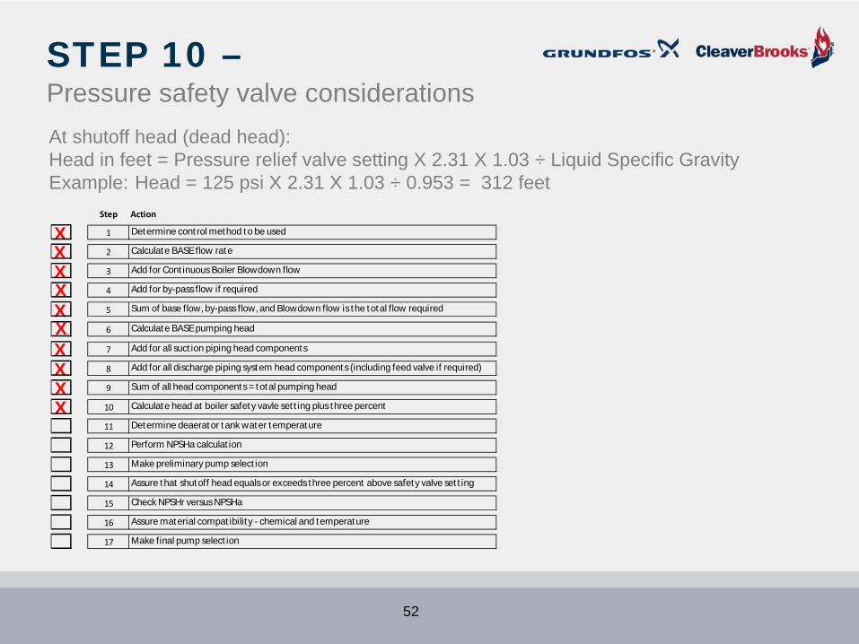

STEP 11 ndashDetermine deaerator tank water temperature
From specification 227degF
53
STEP 12 ndashNPSHa calculation
NPSHa equation
plusmn Elevation + Absolute pressure ndash Vapor Pressure ndash Suction Line Friction = NPSHa
10 feet + (197 psi X 231) - (197 psi X 231) - 2 feet = NPSHa10 feet + 46 feet - 46 feet - 2 feet = 8 feet NPSHa
54
STEP 13 ndashPreliminary pump selection
Conditions of Service Flow = 28 gpmHead = 238 Feet
Does this 10 stage pump pump meet the required flow and head conditions of service
YES
55
STEP 14 ndashPressure safety valve considerations
56
STEP 15 ndashCheck NPSHa vs NPSHr
Conditions of ServiceFlow = 28gpmHead = 238 FeetNPSHa = 8 Feet
bull Pump meets or exceeds flowhead requirement
bull Low-NPSHr first stage = 4 feet required
bull NPSHr safety factor = 2 to 4 feet
bull Target NPSHr = 8 feetbull NPSHa = 8 feet
Does NPSHa equal or exceed NPSHr
YES57
STEP 15 ndashNPSH - ContinuedConditions of Service Flow = 28 gpm Head = 238 Feet NPSHa = 8 FeetThe NPSHa is equal to or exceeds the NPSHr of 8 feet
XXXXXXXXXX
XXXXX
Step Action
1 Determine cont rol method to be used
2 Calculate BASE flow rate
3 Add for Cont inuous Boiler Blowdown flow
4 Add for by-pass flow if required
5 Sum of base flow by-pass flow and Blowdown flow is the total flow required
6 Calculate BASE pumping head
7 Add for all suct ion piping head components
8 Add for all discharge piping system head components (including feed valve if required)
9 Sum of all head components = total pumping head
10 Calculate head at boiler safety vavle set t ing plus three percent
11 Determine deaerator tank water temperature
12 Perform NPSHa calculat ion
13 Make preliminary pump select ion
14 Assure that shutoff head equals or exceeds three percent above safety valve set t ing
15 Check NPSHr versus NPSHa
16 Assure material compat ibilit y - chemical and temperature
17 Make final pump select ion
58
STEP 16 ndashCheck material compatibility
bull Pump materials 316 stainless steelbull Mechanical seal materials Silicon carbidesilicon
carbideEPDM
59
STEP 17 ndashFinal pump selectionPump meets all specification requirements
XXXXXXXXX
X
XXXXXXX
Step Action
1 Determine cont rol method to be used
2 Calculate BASE flow rate
3 Add for Cont inuous Boiler Blowdown flow
4 Add for by-pass flow if required
5 Sum of base flow by-pass flow and Blowdown flow is the total flow required
6 Calculate BASE pumping head
7 Add for all suct ion piping head components
8 Add for all discharge piping system head components (including feed valve if required)
9 Sum of all head components = total pumping head
10 Calculate head at boiler safety vavle set t ing plus three percent
11 Determine deaerator tank water temperature
12 Perform NPSHa calculat ion
13 Make preliminary pump select ion
14 Assure that shutoff head equals or exceeds three percent above safety valve set t ing
15 Check NPSHr versus NPSHa
16 Assure material compat ibilit y - chemical and temperature
17 Make final pump select ion
60
61
SUMMARYbull Steam condensate is a very valuable commodity which needs to saved and used as much as possiblebull Most commonly used boilers for process are industrial firetubes and watertube boilers IWTsbull High pressure condensate flash steam can be used for various purposes such as unit heaters or the
DAbull Condensate can be returned to vented receivers or pressurized deaerators (Spray Tray amp Column)bull Sometimes high pressure condensate receivers are employed Save considerable lossesbull Boiler feed pump selection involves 17 decision points which need to be carefully consideredbull Calculating the pumprsquos base flow rate differs when the pump operates continuously (15 safety factor)
or onoff (50 safety factor)bull Sometimes the base flow rate needs to include for continuous pump re-circulation and maybe for
continuous blow downbull Total Dynamic Head (TDH) is a that pressure the pump must overcome to get water in the boiler and
includes the positive pressure at the pumprsquos inlet after suction pipe losses and the piping losses through the discharge piping before overcoming the boilerrsquos operating pressure
bull Net Positive Suction Head (NPSH) is the pressure required at the pumprsquos suction to mitigate cavitation
bull NPSHA is the NPSH available after all the friction losses on the suction side have been determined in light of the pumprsquos minimum and maximum flow rates
bull The seal selection for the pump is very important and can vary based on the boilerrsquos operating pressuretemperature chemicals in the feed water etc
62
Gregg Achtenhagengachtenhagencleaverbrookscom
Jim Swetyejswetyegrundfoscom
QUESTIONS
63
Over 25000 Grundfos parts are available through your local Cleaver-Brooks RepresentativeVisit cleaverbrookscomreps for all boiler sales and service
| Step | Action | |||||
| 1 | Determine control method to be used | |||||
| 2 | Calculate BASE flow rate | |||||
| 3 | Add for Continuous Boiler Blowdown flow | |||||
| 4 | Add for by-pass flow if required | |||||
| 5 | Sum of base flow by-pass flow and Blowdown flow is the total flow required | |||||
| 6 | Calculate BASE pumping head | |||||
| 7 | Add for all suction piping head components | |||||
| 8 | Add for all discharge piping system head components (including feed valve if required) | |||||
| 9 | Sum of all head components = total pumping head | |||||
| 10 | Calculate head at boiler safety vavle setting plus three percent | |||||
| 11 | Determine deaerator tank water temperature | |||||
| 12 | Perform NPSHa calculation | |||||
| 13 | Make preliminary pump selection | |||||
| 14 | Assure that shutoff head equals or exceeds three percent above safety valve setting | |||||
| 15 | Check NPSHr versus NPSHa | |||||
| 16 | Assure material compatibility - chemical and temperature | |||||
| 17 | Make final pump selection |
| Step | Action | |||||
| 1 | Determine control method to be used | |||||
| 2 | Calculate BASE flow rate | |||||
| 3 | Add for Continuous Boiler Blowdown flow | |||||
| 4 | Add for by-pass flow if required | |||||
| 5 | Sum of base flow by-pass flow and Blowdown flow is the total flow required | |||||
| 6 | Calculate BASE pumping head | |||||
| 7 | Add for all suction piping head components | |||||
| 8 | Add for all discharge piping system head components (including feed valve if required) | |||||
| 9 | Sum of all head components = total pumping head | |||||
| 10 | Calculate head at boiler safety vavle setting plus three percent | |||||
| 11 | Determine deaerator tank water temperature | |||||
| 12 | Perform NPSHa calculation | |||||
| 13 | Make preliminary pump selection | |||||
| 14 | Assure that shutoff head equals or exceeds three percent above safety valve setting | |||||
| 15 | Check NPSHr versus NPSHa | |||||
| 16 | Assure material compatibility - chemical and temperature | |||||
| 17 | Make final pump selection |
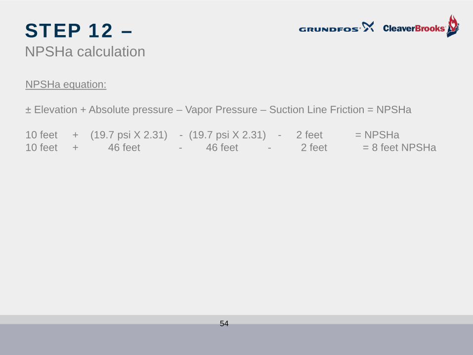
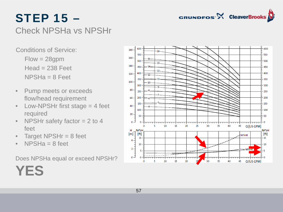

STEP 16 ndashCheck material compatibility
bull Pump materials 316 stainless steelbull Mechanical seal materials Silicon carbidesilicon
carbideEPDM
59
STEP 17 ndashFinal pump selectionPump meets all specification requirements
XXXXXXXXX
X
XXXXXXX
Step Action
1 Determine cont rol method to be used
2 Calculate BASE flow rate
3 Add for Cont inuous Boiler Blowdown flow
4 Add for by-pass flow if required
5 Sum of base flow by-pass flow and Blowdown flow is the total flow required
6 Calculate BASE pumping head
7 Add for all suct ion piping head components
8 Add for all discharge piping system head components (including feed valve if required)
9 Sum of all head components = total pumping head
10 Calculate head at boiler safety vavle set t ing plus three percent
11 Determine deaerator tank water temperature
12 Perform NPSHa calculat ion
13 Make preliminary pump select ion
14 Assure that shutoff head equals or exceeds three percent above safety valve set t ing
15 Check NPSHr versus NPSHa
16 Assure material compat ibilit y - chemical and temperature
17 Make final pump select ion
60
61
SUMMARYbull Steam condensate is a very valuable commodity which needs to saved and used as much as possiblebull Most commonly used boilers for process are industrial firetubes and watertube boilers IWTsbull High pressure condensate flash steam can be used for various purposes such as unit heaters or the
DAbull Condensate can be returned to vented receivers or pressurized deaerators (Spray Tray amp Column)bull Sometimes high pressure condensate receivers are employed Save considerable lossesbull Boiler feed pump selection involves 17 decision points which need to be carefully consideredbull Calculating the pumprsquos base flow rate differs when the pump operates continuously (15 safety factor)
or onoff (50 safety factor)bull Sometimes the base flow rate needs to include for continuous pump re-circulation and maybe for
continuous blow downbull Total Dynamic Head (TDH) is a that pressure the pump must overcome to get water in the boiler and
includes the positive pressure at the pumprsquos inlet after suction pipe losses and the piping losses through the discharge piping before overcoming the boilerrsquos operating pressure
bull Net Positive Suction Head (NPSH) is the pressure required at the pumprsquos suction to mitigate cavitation
bull NPSHA is the NPSH available after all the friction losses on the suction side have been determined in light of the pumprsquos minimum and maximum flow rates
bull The seal selection for the pump is very important and can vary based on the boilerrsquos operating pressuretemperature chemicals in the feed water etc
62
Gregg Achtenhagengachtenhagencleaverbrookscom
Jim Swetyejswetyegrundfoscom
QUESTIONS
63
Over 25000 Grundfos parts are available through your local Cleaver-Brooks RepresentativeVisit cleaverbrookscomreps for all boiler sales and service
| Step | Action | |||||
| 1 | Determine control method to be used | |||||
| 2 | Calculate BASE flow rate | |||||
| 3 | Add for Continuous Boiler Blowdown flow | |||||
| 4 | Add for by-pass flow if required | |||||
| 5 | Sum of base flow by-pass flow and Blowdown flow is the total flow required | |||||
| 6 | Calculate BASE pumping head | |||||
| 7 | Add for all suction piping head components | |||||
| 8 | Add for all discharge piping system head components (including feed valve if required) | |||||
| 9 | Sum of all head components = total pumping head | |||||
| 10 | Calculate head at boiler safety vavle setting plus three percent | |||||
| 11 | Determine deaerator tank water temperature | |||||
| 12 | Perform NPSHa calculation | |||||
| 13 | Make preliminary pump selection | |||||
| 14 | Assure that shutoff head equals or exceeds three percent above safety valve setting | |||||
| 15 | Check NPSHr versus NPSHa | |||||
| 16 | Assure material compatibility - chemical and temperature | |||||
| 17 | Make final pump selection |

61
SUMMARYbull Steam condensate is a very valuable commodity which needs to saved and used as much as possiblebull Most commonly used boilers for process are industrial firetubes and watertube boilers IWTsbull High pressure condensate flash steam can be used for various purposes such as unit heaters or the
DAbull Condensate can be returned to vented receivers or pressurized deaerators (Spray Tray amp Column)bull Sometimes high pressure condensate receivers are employed Save considerable lossesbull Boiler feed pump selection involves 17 decision points which need to be carefully consideredbull Calculating the pumprsquos base flow rate differs when the pump operates continuously (15 safety factor)
or onoff (50 safety factor)bull Sometimes the base flow rate needs to include for continuous pump re-circulation and maybe for
continuous blow downbull Total Dynamic Head (TDH) is a that pressure the pump must overcome to get water in the boiler and
includes the positive pressure at the pumprsquos inlet after suction pipe losses and the piping losses through the discharge piping before overcoming the boilerrsquos operating pressure
bull Net Positive Suction Head (NPSH) is the pressure required at the pumprsquos suction to mitigate cavitation
bull NPSHA is the NPSH available after all the friction losses on the suction side have been determined in light of the pumprsquos minimum and maximum flow rates
bull The seal selection for the pump is very important and can vary based on the boilerrsquos operating pressuretemperature chemicals in the feed water etc
62
Gregg Achtenhagengachtenhagencleaverbrookscom
Jim Swetyejswetyegrundfoscom
QUESTIONS
63
Over 25000 Grundfos parts are available through your local Cleaver-Brooks RepresentativeVisit cleaverbrookscomreps for all boiler sales and service

Gregg Achtenhagengachtenhagencleaverbrookscom
Jim Swetyejswetyegrundfoscom
QUESTIONS
63
Over 25000 Grundfos parts are available through your local Cleaver-Brooks RepresentativeVisit cleaverbrookscomreps for all boiler sales and service
Copyright © 2022 FDOCUMENTS