Boiler Controls McDonnell &...
45
27 Boiler Controls Boiler Controls McDonnell & Miller 27 McDonnell & Miller Low Water Cut-offs are specially designed to protect steam boilers from the hazards of a low water condition. In operation they will interrupt the electrical current to the firing device, if the water in the system drops below the boiler manufacturers’ minimum safe water level. Our low water cut-offs also provide an additional circuit for a water feeder or a low water alarm, should you desire to install one, for additional protection. How to Select Low Water Cut-Offs for Steam Boilers Boiler pressure and the method of installation are the primary factors to consider when selecting a low water cut-off. Steam Boilers Maximum Method of Installation Blow Down Valve Boiler Connect to the Provided with Pressure Directly into Boiler with 1" Product Size Low Water psi (kg/cm 2 ) Boiler Tappings* Equalizing Piping Series NPT Required Cut-Off 15 (1) X PS-800 3 /4 No N/A X 750/750B/750P 3 /4 No N/A X 61 1 Yes No X 67 1 /2 Yes Yes 20 (1.4) X 767 2 1 /2 Yes Yes X 69 2 1 /2 No N/A X 42S 1 Yes No 50 (3.5) X 42S-A 1 /2 Yes Yes X 63 1 Yes No X 64 1 Yes No X 64-A 1 /2 Yes Yes X 764 2 1 /2 Yes No 150 (10.5) X 93/193 1 Yes No X 150S/150E 1 Yes No X 157S/157E 1 Yes No 250 (18) 1 1 /4 94/194 1 1 /4 Yes No X 750B-C3/C4 1 Yes No * Use the tapping designated by the boiler manufacturer for low water cut-off installation. We recommend that secondary (redundant) Low Water Cut-Off controls be installed on all steam boilers with heat input greater than 400,000 BTU/hour or operating above 15 psi of steam pressure. At least two controls should be connected in series with the burner control circuit to provide safety redundancy protection should the boiler experience a low water condition. Moreover, at each annual outage, the low water cut-offs should be dismantled, inspected, cleaned, and checked for proper calibration and performance.
Transcript of Boiler Controls McDonnell &...

27
Boiler C
ontro
ls
Boiler Controls McDonnell & Miller
27
McDonnell & Miller Low Water Cut-offs are speciallydesigned to protect steam boilers from the hazards of alow water condition. In operation they will interrupt theelectrical current to the firing device, if the water in thesystem drops below the boiler manufacturers’ minimumsafe water level.
Our low water cut-offs also provide an additional circuit fora water feeder or a low water alarm, should you desire toinstall one, for additional protection.
How to Select Low WaterCut-Offs for Steam BoilersBoiler pressure and the method of installation are theprimary factors to consider when selecting a low watercut-off.
Steam Boilers
Maximum Method of Installation Blow Down ValveBoiler Connect to the Provided with
Pressure Directly into Boiler with 1" Product Size Low Waterpsi (kg/cm2) Boiler Tappings* Equalizing Piping Series NPT Required Cut-Off
15 (1)X PS-800 3⁄4 No N/A
X 750/750B/750P 3⁄4 No N/A
X 61 1 Yes No
X 67 1⁄2 Yes Yes
20 (1.4) X 767 21⁄2 Yes Yes
X 69 21⁄2 No N/A
X 42S 1 Yes No
50 (3.5) X 42S-A 1⁄2 Yes Yes
X 63 1 Yes No
X 64 1 Yes No
X 64-A 1⁄2 Yes Yes
X 764 21⁄2 Yes No
150 (10.5)X 93/193 1 Yes No
X 150S/150E 1 Yes No
X 157S/157E 1 Yes No
250 (18) 11⁄4 94/194 11⁄4 Yes No
X 750B-C3/C4 1 Yes No
* Use the tapping designated by the boiler manufacturer for low water cut-off installation.
We recommend that secondary (redundant) Low WaterCut-Off controls be installed on all steam boilers with heatinput greater than 400,000 BTU/hour or operating above15 psi of steam pressure. At least two controls should beconnected in series with the burner control circuit toprovide safety redundancy protection should the boilerexperience a low water condition. Moreover, at eachannual outage, the low water cut-offs should bedismantled, inspected, cleaned, and checked for propercalibration and performance.
04_LWCOpgs 27-41 COLLECT 3/6/07 6:29 PM Page 27

28
Boile
r C
ontr
ols
Boiler Controls McDonnell & Miller
28
Boiler RatingBTU HP EDR Cond. Lb./Hr
33,475 1 140 34.5
66,950 2 280 69
167,375 5 700 173
251,063 7.5 1,050 259
334,750 10 1,400 345
418,438 12.5 1,750 431
502,125 15 2,100 518
585,813 17.5 2,450 604
669,500 20 2,800 690
836,875 25 3,500 863
1,004,250 30 4,200 1,035
1,171,625 35 4,900 1,208
1,339,000 40 5,600 1,380
1,506,375 45 6,300 1,553
1,673,750 50 7,000 1,725
How to Select ControlsSTEAM BOILERSSteam Heating Boilers are classified as boilers in closedheating systems where all condensate is returned to theboiler. Best recommendation for all automatically firedboilers is a feeder cut-off combination. It adds water asneeded to maintain a safe operating level, and stands byto interrupt circuit to burner if water level drops intoemergency zone.Steam Process Boilers are classified as boilers insystems where not all the condensate is returned, andsome make-up water is needed. A separate feeder andseparate cut-off are recommended, so operating levelscan be set for the wider differential required in suchservice.Selection of the correct feeder cut-off combination, orfeeder depends upon:1. Maximum boiler pressure.2. Differential between water supply pressure and thepressure setting of the steam safety valve.3. Boiler sizeHOT WATER BOILERSBest recommendation for all automatically fired boilers isa feeder cut-off combination. It adds water if needed tomatch the discharge capacity of the relief valve, andstands by to interrupt circuit to burner if water level dropsinto emergency zone.Selection of the correct feeder cut-off combination, orfeeder depends upon:1. Maximum boiler pressure.2. Differential between water supply pressure and thepressure setting of the safety relief valve.3. Boiler size
Water Feeders and CombinationWater Feeders/Low Water Cut-Offs
Conversion Factors
Boiler Steaming Rate (Gallons Per Minute)
EDR139
BTUH240
Lbs. of Water8.33
EDR x 240
BHP x 33,479
Boiler Horsepower (BHP)
Gallons of Water
BTUH
EDR
BTUH
=
=
=
=
=
EDR2000
GPM = (BHP) x 0.069
EDR x 0.000496
GPM =
BTU480,000GPM =
GPM =
Pounds ofcondensate per hour
=EDR
4
McDonnell & Miller Boiler Water Feeders and Feeder Cut-Off Combinations are used to provide automatic operation,and to safeguard steam and hot water boilers against thehazards of a low water condition.
A feeder cut-off combination mechanically adds water asneeded to maintain the required minimum water level, andelectrically stops the firing device in case of anemergency.
04_LWCOpgs 27-41 COLLECT 3/6/07 6:29 PM Page 28

29
Boiler C
ontro
ls
McDonnell & Miller
29
Maximum Boiler Size
Boiler (Mfr. Gross Rating Sq. Ft. of EDR)Series Characteristics Pressure *Differential Pressure psi (kg/cm2)
psi (kg/cm2) 10 (.7) 20 (1.4) 30 (2.1) 40 (2.8) 50 (3.5) 60 (4.2) 70 (4.9)
Uni-Match® For Automatic Fired 15 (1.0) All Boilers up to 2,000 sq. ft.Heating Boilers
101A For Automatic Fired 25 (1.8) All Boilers up to 5,000 sq. ft.Heating Boilers
47 For Heating or 25 (1.8) All Boilers up to 5,000 sq. ft.Process Boilers
47-2 For Automatic Fired 25 (1.8) All Boilers up to 5,000 sq. ft.Heating Boilers
247 For Heating or 30 (2.1) All Boilers up to 5,000 sq. ft.Process Boilers
247-2 For Automatic Fired 30 (2.1) All Boilers up to 5,000 sq. ft.Heating Boilers
51 For Heating or 35 (2.5) 8,600 12,000 15,000 17,600 20,000 21,800 23,400Process Boilers
51-2 For Automatic Fired 35 (2.5) 8,600 12,000 15,000 17,600 20,000 21,800 23,400Heating Boilers
51S For Heating or 35 (2.5) 10,500 17,500 22,400 26,500 30,000 32,600 35,000Process Boilers
51S-2 For Automatic Fired 35 (2.5) 10,500 17,500 22,400 26,500 30,000 32,600 35,000Heating Boilers
53 For Heating or 75 (5.3) 8,600 11,600 14,600 17,000 18,800 20,600 22,100Process Boilers
53-2 For Automatic Fired 75 (5.3) 8,600 11,600 14,600 17,000 18,800 20,600 22,100Heating Boilers
Steam Boilers
*Differential pressure should be based on water supply pressure at boiler, minus pressure setting of steam safety valve
How to Select Water Feeders (continued)
Boiler Controls
04_LWCOpgs 27-41 COLLECT 3/6/07 6:29 PM Page 29

30
Boile
r C
ontr
ols
Boiler Controls McDonnell & Miller
30
NOW WITH
SELF-CLEANING
PROBE!
Low Water Cut-Offs – ElectronicFor Hot Water and Steam Boilers
Series 750Low Water Cut-Offs with Remote Sensor• For commercial or industrial applications
• Primary or secondary control on hot water boilers
• Secondary control (manual reset models only) on steamboilers
• Manual reset models meet the requirements of ASMEStandard CSD-1. If the control is in a low watercondition when there is an interruption of power, thecontrol will remain in a low water condition when poweris restored. The reset button will need to be pressedwhen the water level is restored to a level above theprobe to allow the burner to fire.
• Green LED power indicating light
• Red LED low water indicating light
• Test switch
• 20,000 ohms sensitivity
• Options:- Manual reset button- 750P-MT model includes PA-800 probe- 750P-MT-U model includes PA-800-U probe
• NEMA 1 enclosure
• Maximum ambient temperature 120°F (49°C)
Series 750Control Unit
A B C D E F GStd. U Std U NPT
63⁄8 (162) 51⁄8 (130) 29⁄16 (65) 19⁄16 (40) 31⁄16 (78) 21⁄8 (54) 19⁄16 (40) 3⁄4 3⁄4 (20)
Dimensions, in. (mm)
Ordering Information(Remote sensor must be ordered separately ((see page 72-74)
Model Part WeightNumber Number Description lbs. (kg)
750-T-120 176206 Auto reset 2 (.9)750-MT-120 176207 Manual reset 2 (.9)750P-MT-120 176234 Manual reset and PA-800 probe 2.5 (.9)750P-MT-U-120 176214 Manual reset and PA-800-U probe 2.5 (.9)
®
750P-MT-120750P-MT-U-120
A
B
C D E
FG
®
Electrical RatingsMotor Switch Rating (Amperes)
Voltage Full Load Locked Rotor Pilot Duty
120 VAC 7.2 43.2 125 VA at
240 VAC 3.6 21.6120 or 240 VAC
50 or 60 Hz
04_LWCOpgs 27-41 COLLECT 3/6/07 6:29 PM Page 30

31
Boiler C
ontro
ls
Boiler Controls McDonnell & Miller
Model 750-HW-MT-120The 750-HW-MT-120 control provides continuousprotection against a HIGH WATER condition in steamboilers and other water level applications. It can be wiredto provide alarm, turn off boiler or turn off water feederpumps when a HIGH WATER condition occurs. Themanual reset function will require the unit be reset afterwater has dropped below the level of the probe.
• For commercial or industrial applications
• Primary or secondary control on hot water boilers
• Green LED power indicating light
• Red LED HIGH WATER indicating light
• Manual Reset
• Test switch
• 20,000 ohms sensitivity
• NEMA 1 enclosure
• Maximum ambient temperature 120°F (49°C)
Model 750-HW-MT-120Control Unit
A B C D
63⁄8 (162) 51⁄8 (130) 29⁄16 (65) 3⁄4 (20)
Dimensions, in. (mm)
Ordering Information(Remote sensor must be ordered separately (see page 72-74)
Model Part WeightNumber Number Description lbs. (kg)
750-HW-MT-120 176236 Manual reset 2 (.9)
®
A
B
C
D
Electrical RatingsMotor Switch Rating (Amperes)
Voltage Full Load Locked Rotor Pilot Duty
120 VAC 7.2 43.2 125 VA at
240 VAC 3.6 21.6120 or 240 VAC
50 or 60 Hz
High Water Cut-Offs – ElectronicFor Steam Boilers
04_LWCOpgs 27-41 COLLECT 3/6/07 6:29 PM Page 31

32
Boile
r C
ontr
ols
Boiler Controls McDonnell & Miller
Series PS-800
J
K
CA
F
E
G HD
B
Low Water Cut-Offs – ElectronicFor Steam BoilersNew and ImprovedSeries PS-800Low Water Cut-Offs
• For residential and commercial applications
• Electronic operation
New Features:• User-friendly diagnostics
- Red low water and shorted probe LED- Green power and test LED
• Probe sensitivity: 7,000 ohms
• No lock out with loss of power if probe is in water
• Delay on Make (DOM) feature (15 seconds)
• Delay on Break (DOB) feature (10 seconds)
• No blow down of control required when mounted directlyinto boiler tappings
• Test button standard on all models
• Options available include
– Manual reset
– Extended barrel and remote sensor models
– 120 volt and 24 volt models (24 volt models meet ANSI specification Z21.13a)
• Power consumption 1.7 VA
• Provisions to add alarm or automatic water feeder
• Maximum ambient temperature 120°F (49°C)
• Maximum steam pressure 15 psi (1 kg/cm2)
• Maximum water temperature 250°F (121°C)
®
®
Ordering InformationModel Part WeightNumber Number Description lbs. (kg)
PS-801-120 153875 Low water cut-off 120V 2.7 (1.2)PS-801-M-120 153880 PS-801-120 w/manual reset 2.7 (1.2)PS-801-U-120 153876 PS-801-120 w/ext. barrel 2.7 (1.2)PS-801-M-U-120 153925 PS-801-120 w/ext. barrel 2.7 (1.2)
& manual resetPS-802-24 153917 Low water cut-off 24V 2.7 (1.2)PS-802-M-24 153913 PS-802-24 w/manual reset 2.7 (1.2)PS-802-U-24 153916 PS-802-24 w/ext. barrel 2.7 (1.2)PS-802-M-U-24 153924 PS-802-24 w/ext. barrel 2.7 (1.2)
& manual resetPS-802-RX2-24 153914 PS-802-24 w/remote sensor 2.7 (1.2)
Electrical Ratings
Motor Switch Rating (Amperes)Model Voltage Full Load Locked Rotor Pilot Duty
24 VAC 24 VAC — — 50 VA at24 VAC
120 VAC120 VAC 7.5 43.2 125 VA at
240 VAC 3.75 21.6 120 or 240 VAC
50 or 60 Hz
Dimensions, in. (mm)A B C D E F G H J K
All U Std SP RX2 U All RX
41⁄4 (108) 19⁄16 (40) 31⁄16 (78) 21⁄8 (54) 13⁄8 (35) 21⁄8 (54) 19⁄16 (40) 3⁄4 (20) 13⁄16 (21) 513⁄16 (148) 13⁄8 (35) 3⁄4 NPT 1⁄2 NPT 27⁄8 (73) 7⁄8 (22)
CAUTIONDo not use “manual reset” models with electricautomatic water feeders.Failure to follow this caution can cause flooding andproperty damage.
NOW WITH
SELF-CLEANING
PROBE!
04_LWCOpgs 27-41 COLLECT 3/6/07 6:29 PM Page 32
33
Boiler C
ontro
ls
Boiler Controls McDonnell & Miller
J
K
CA
F
E
G HD
B
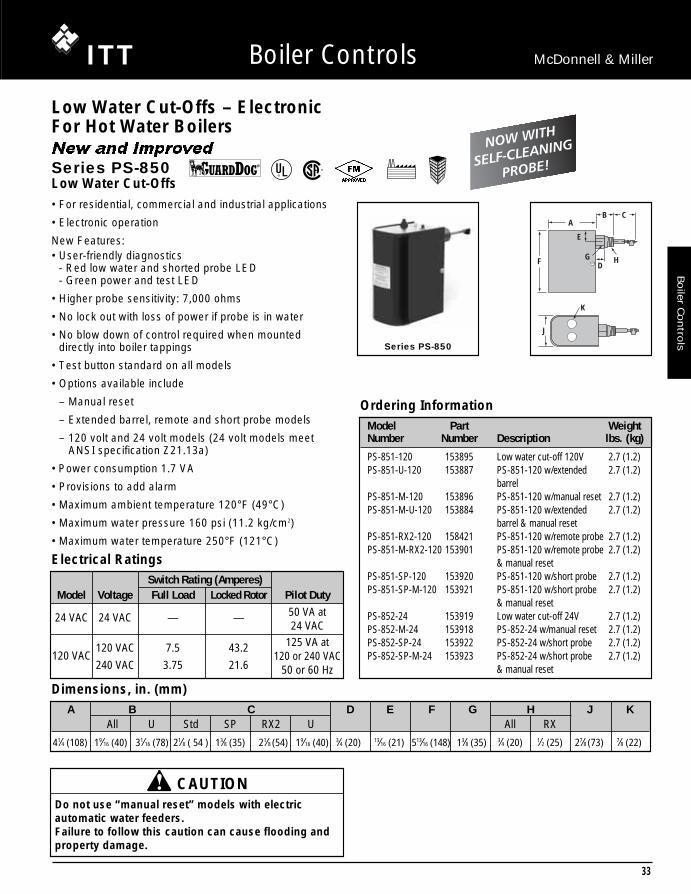
Series PS-850
• For residential, commercial and industrial applications
• Electronic operation
New Features:• User-friendly diagnostics
- Red low water and shorted probe LED- Green power and test LED
• Higher probe sensitivity: 7,000 ohms
• No lock out with loss of power if probe is in water
• No blow down of control required when mounteddirectly into boiler tappings
• Test button standard on all models
• Options available include
– Manual reset
– Extended barrel, remote and short probe models
– 120 volt and 24 volt models (24 volt models meet ANSI specification Z21.13a)
• Power consumption 1.7 VA
• Provisions to add alarm
• Maximum ambient temperature 120°F (49°C)
• Maximum water pressure 160 psi (11.2 kg/cm2)
• Maximum water temperature 250°F (121°C)
New and Improved
Series PS-850Low Water Cut-Offs
Electrical Ratings
Ordering Information
Dimensions, in. (mm)
Model Part WeightNumber Number Description lbs. (kg)
PS-851-120 153895 Low water cut-off 120V 2.7 (1.2)PS-851-U-120 153887 PS-851-120 w/extended 2.7 (1.2)
barrelPS-851-M-120 153896 PS-851-120 w/manual reset 2.7 (1.2)PS-851-M-U-120 153884 PS-851-120 w/extended 2.7 (1.2)
barrel & manual resetPS-851-RX2-120 158421 PS-851-120 w/remote probe 2.7 (1.2)PS-851-M-RX2-120 153901 PS-851-120 w/remote probe 2.7 (1.2)
& manual resetPS-851-SP-120 153920 PS-851-120 w/short probe 2.7 (1.2)PS-851-SP-M-120 153921 PS-851-120 w/short probe 2.7 (1.2)
& manual resetPS-852-24 153919 Low water cut-off 24V 2.7 (1.2)PS-852-M-24 153918 PS-852-24 w/manual reset 2.7 (1.2)PS-852-SP-24 153922 PS-852-24 w/short probe 2.7 (1.2)PS-852-SP-M-24 153923 PS-852-24 w/short probe 2.7 (1.2)
& manual reset
A B C D E F G H J KAll U Std SP RX2 U All RX
41⁄4 (108) 19⁄16 (40) 31⁄16 (78) 21⁄8 ( 54 ) 13⁄8 (35) 21⁄8 (54) 19⁄16 (40) 3⁄4 (20) 13⁄16 (21) 513⁄16 (148) 13⁄8 (35) 3⁄4 (20) 1⁄2 (25) 27⁄8 (73) 7⁄8 (22)
Low Water Cut-Offs – ElectronicFor Hot Water Boilers
CAUTIONDo not use “manual reset” models with electricautomatic water feeders.Failure to follow this caution can cause flooding andproperty damage.
Switch Rating (Amperes)Model Voltage Full Load Locked Rotor Pilot Duty
24 VAC 24 VAC — — 50 VA at24 VAC
120 VAC120 VAC 7.5 43.2 125 VA at
240 VAC 3.75 21.6 120 or 240 VAC
50 or 60 Hz
®
®
NOW WITH
SELF-CLEANING
PROBE!
04_LWCOpgs 27-41 COLLECT 3/6/07 6:29 PM Page 33
34
Boile
r C
ontr
ols
Boiler Controls McDonnell & Miller
Low Water Cut-Offs – ElectronicFor Hot Water Boilers
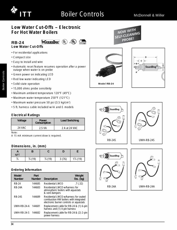
RB-24Low Water Cut-Offs
• For residential applications
• Compact size
• Easy to install and wire
• Automatic reset feature resumes operation after a poweroutage when water is on probe
• Green power on indicating LED
• Red low water indicating LED
• Solid state operation
• 15,000 ohms probe sensitivity
• Maximum ambient temperature 120°F (49°C)
• Maximum water temperature 250°F (121°C)
• Maximum water pressure 50 psi (3.5 kg/cm2)
• 5 ft. harness cable included w/-A and-S models
Model RB-24
Electrical Ratings
A B C D ENPT
3⁄4 3⁄4 (19) 3⁄4 (19) 3 (76) 13⁄4 (19)
Dimensions, in. (mm)
Ordering Information
Model Part WeightNumber Number Description lbs. (kg)
RB-24 144685 Residential LWCO .7 (.32)RB-24A 144683 Residential LWCO w/harness for
atmospheric boilers with aquastats & vent dampers
RB-24S 144689 Residential LWCO w/harness for sealed combustion HW boilers with integrated electronic burner controls or aquastats
UWH-RB-24-A 144681 Replacement cable for RB-24 & (1) 6-pin harness and (1) 4-pin harness
UWH-RB-24-S 144682 Replacement cable for RB-24 & (2) 2-pin power harness
A
B
C
D
E
®
Note:A 15 mA minimum current draw is required.
Voltage Power Load SwitchingConsumption
24 VAC 2.5 VA 2 A at 24 VAC
RB-24S
RB-24A
UWH-RB-24S
UWH-RB-24A
NOW WITH
SELF-CLEANING
PROBE!
04_LWCOpgs 27-41 COLLECT 3/6/07 6:29 PM Page 34
35
Boiler C
ontro
ls
Boiler Controls McDonnell & Miller
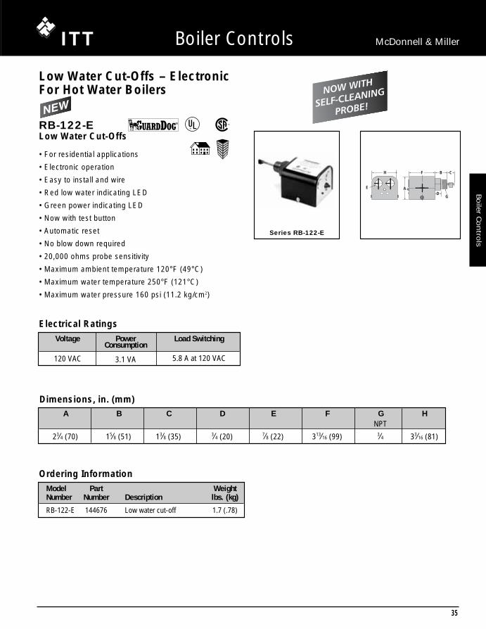
Series RB-122-E
H
E
F B
D
C
A
G
Low Water Cut-Offs – ElectronicFor Hot Water Boilers
RB-122-ELow Water Cut-Offs
• For residential applications
• Electronic operation
• Easy to install and wire
• Red low water indicating LED
• Green power indicating LED
• Now with test button
• Automatic reset
• No blow down required
• 20,000 ohms probe sensitivity
• Maximum ambient temperature 120°F (49°C)
• Maximum water temperature 250°F (121°C)
• Maximum water pressure 160 psi (11.2 kg/cm2)
Ordering InformationModel Part WeightNumber Number Description lbs. (kg)
RB-122-E 144676 Low water cut-off 1.7 (.78)
A B C D E F G HNPT
23⁄4 (70) 15⁄8 (51) 13⁄8 (35) 3⁄4 (20) 7⁄8 (22) 313⁄16 (99) 3⁄4 33⁄16 (81)
Dimensions, in. (mm)
®
®
Electrical Ratings
Voltage Power Load SwitchingConsumption
120 VAC 3.1 VA 5.8 A at 120 VAC
NOW WITH
SELF-CLEANING
PROBE!
04_LWCOpgs 27-41 COLLECT 3/6/07 6:29 PM Page 35

36
Boile
r C
ontr
ols
Boiler Controls McDonnell & Miller
Series RB-120
A
B
C D E
FG
Low Water Cut-Offs – ElectronicFor Hot Water Boilers
RB-120Low Water Cut-Offs
• For residential and (where codes allow) commercial applications
• Electro-mechanical operation
• Automatic reset feature resumes operation after a power outage when water is on probe
• No blow down required
• 6,000 ohms probe sensitivity
• Maximum ambient temperature 120°F (49°C)
• Maximum water temperature 250°F (121°C)
• Maximum water pressure 160 psi (11.2 kg/cm2)
Ordering InformationModel Part WeightNumber Number Description lbs. (kg)
RB-120 144675 Low water cut-off 3.8 (1.7)
A B C D E F GNPT
63⁄8 (162) 51⁄8 (130) 29⁄16 (65) 15⁄8 (41) 13⁄8 (35) 3⁄4 (20) 7⁄8
Dimensions, in. (mm)
®
®
Electrical Ratings
Voltage Power Load SwitchingConsumption
120 VAC 15 VA 5.8 A at 120 VAC
NOW WITH
SELF-CLEANING
PROBE!
04_LWCOpgs 27-41 COLLECT 3/6/07 6:29 PM Page 36

37
Boiler C
ontro
ls
Boiler Controls McDonnell & Miller
G
H
E
D
J
C
F
J
K
A
B
L A
CUT OFFLEVEL
H
G
E
J
J
FD
Series 150E
Series 157E
Series 150E• Primary and secondary low water fuel cut-off protection
and pump control for commercial and industrial steamboilers
• Motorized valve controller, low water cut-off, and alarmactuators for boilers, vessels and tanks
• Set points and differentials remain constant throughoutpressure range
• Diagnostic features incorporated in the control include:– High ambient temperature protection– Internal LEDs that indicate water position and condition– External LEDs that indicate control activity
• Replacement head assemblies available for Model 150and 150S Series upgrade
• Control unit can be mounted remotely from probes• Adjustable 60-second burner-off time delays• Adjustable 3/4” or 1-3/16” pump differentials• 1 HP burner and pump relays• NEMA 1 enclosure• Maximum ambient temperature 135°F (57°C)• Maximum operating pressure 150 psi (10.5 kg/cm2)• Maximum operating temperature 366°F (185°C) at probes• Manual reset models meet the requirements of ASME
Standard CSD-1. If the control is in a low water conditionwhen there is an interruption of power, the control willremain in a low water condition when power is restored.The reset button will need to be pressed when the waterlevel is restored to a level above the probe to allow theburner to fire.
• 60,000 ohms probe sensitivity
®
®
Electrical Rating and Switch RatingsSupply Probe Full load (Amps) Locked Rotor (Amps) Pilot Duty (VA) Motor (HP)Voltage Voltage NO (NC), (VAC) NO (NC), (VAC) NO (NC), (VAC) NO (NC), (VAC)120 VAC 5 VAC 16 (5.8), 120 96 (34.8), 120 470 (290), 120 1 (1/4), 12050/60Hz Maximum 8 (4.9), 240 48 (17.4), 240 470 (290), 240 2 (1/2), 240
A
B
C
CUT-OFFLEVEL
A B C D E
611⁄16 (169)115⁄16 (286) 6 (152) 143⁄16 (359) 35⁄16 (84)
Series 150E Dimensions, in. (mm)
F G H JNPT
107⁄8 (275) 41⁄8 (105) 37⁄16 (87) 1
A B C D ENPT NPT
1 1⁄2 145⁄16 (362) 25⁄16 (59) 415⁄16 (125)
Series 157E Dimensions, in. (mm)
F G H J K LNPT
125⁄8 (319) 16 (406) 111⁄2 (292) 31⁄2 (89) 3⁄4 57⁄8 (149)
Model Part WeightNumber Number Description lbs. (kg.)150E 171600 Combination low water 22.9 (10.4)
cut-off/pump controller150E-M 171610 150E w/manual reset 22.9 (10.4)157E 171620 150E w/water column 36.9 (16.7)157E-M 171630 157E w/manual reset 36.9 (16.7)157E-A 171622 157E w/alternate tappings 39.0 (17.5)157E-R 171623 157E w/alternate tappings 39.0 (17.5)157E-RM 171633 157E w/alternate tappings 39.0 (17.5)157E-RL 171626 157E w/alternate tappings 39.0 (17.5)157E-RLM 171636 157E w/alternate tappings 39.0 (17.5)
Ordering Information
Low Water Cut-Offs – ElectronicCombination Low Water Cut-Off/Pump Controllers for Steam Boilers
04_LWCOpgs 27-41 COLLECT 3/6/07 6:29 PM Page 37

38
Boiler Controls McDonnell & Miller
Boile
r Contr
ols
• For residential and commercial low pressure steamboiler applications
• For boilers of any steaming capacity
• Adjustable BX outlet for easy installation
• Dual precision switches for dependable operation of thelow water cut-off and alarm or electric water feeder
• Packless bellows
• 1" NPT equalizing pipes and blow down valve required
• Maximum steam pressure 20 psi (1.4 kg/cm2) Series 61
G
AB
F
D
E CUT-OFFLEVEL
C
Low Water Cut-Offs – MechanicalFor Steam BoilersSeries 61Low Water Cut-Offs
Ordering Information
Electrical Ratings
Dimensions, in. (mm)
Model Part WeightNumber Number Description lbs. (kg)
61 140100 Low water cut-off 13.5 (6.1)
A B C D E F GNPT NPT
915⁄16 (252) 77⁄16 (189) 1 1 61⁄2 (165) 31⁄8 (79) 51⁄8 (130)
Motor Switch Rating (Amperes)120 VDC .3 Amp, 240 VDC .15 Amp
Voltage Full Load Locked Rotor Pilot Duty120 VAC 7.4 44.4 125 VA at 120240 VAC 3.7 22.2 or 240 VAC
®
®
04_LWCOpgs 27-41 COLLECT 3/6/07 6:29 PM Page 38

39
Boiler C
ontro
ls
Boiler Controls McDonnell & Miller
A B C D E F G H JNPT NPT
1 61⁄2 (165) 29⁄16 (65) 1 55⁄32 (131) 93⁄8 (238) 31⁄8 (79) 101⁄2 (267) 51⁄8 (130)
CUT OFFLEVELB
C
G
H
FE
A
D
J
Series 63
Series 63Low Water Cut-Offs
• For residential, commercial, and industrial applications
• Heavy duty
• Includes No. 2 switch
• Optional manual reset available
• Maximum boiler pressure 50 psi (3.5 kg/cm2)
• Use with TC-4 on hot water systems
Ordering Information
Dimensions, in. (mm)
Model Part WeightNumber Number Description lbs. (kg)
63 142400 Low water cut-off 13.5 (6.1)63-B 142700 63 w/ float block 15.0 (6.8)63-BM 143300 63 w/float block & manual reset 15.0 (6.8)63-M 143100 63 w/manual reset 14.0 (6.4)
Electrical Ratings
®
®
Motor Switch Rating (Amperes)120 VDC .5 Amp
Voltage Full Load Locked Rotor Pilot Duty
120 VAC 10.2 61.2 125 VA at
240 VAC 5.1 30.6120 or 240 VAC
60 Hz
Low Water Cut-Offs – MechanicalFor Steam and Hot Water Boilers
04_LWCOpgs 27-41 COLLECT 3/6/07 6:29 PM Page 39

40
Boile
r C
ontr
ols
Boiler Controls McDonnell & Miller
A B C D E FNPT NPT
915⁄16 (252) 77⁄16 (65) 1 61⁄2 (165) 31⁄8 (79) 1
AB
E
F
D CUT-OFFLEVEL
C
SERIES 64
Low Water Cut-Offs – MechanicalFor Steam and Hot Water BoilersSeries 64Low Water Cut-Offs
• Quick hook-up fittings provided for installation directlyinto gauge glass tappings
Model 64-A
A B
C
ED
G
F
CUT-OFFLEVEL
• For residential, commercial, and industrial boilerapplications of any steaming capacity
• Heavy Duty
• Adjustable BX outlet for easy installation
• Dual precision switches for dependable operation of thelow water cut-off and alarm or electric water feeder
• Packless bellows
• Optional manual reset available
• 1" (25mm) NPT equalizing pipes required
• Maximum boiler pressure 50 psi (3.5 kg/cm2)
• Use with TC-4 on hot water systems
Dimensions, in. (mm)
Ordering Information
®
Model Part WeightNumber Number Description lbs. (kg)
64 143600 Low water cut-off 11.3 (5.1)64-A 143700 64 w/quick hook-up fittings 18.3 (8.3)64-B 143800 64 w/float block 11.5 (5.2)64-M 144250 64 w/manual reset 12.5 (5.7)
®
Electrical Ratings
Model 64-ALow Water Cut-Offs
Motor Switch Rating (Amperes)Voltage Full Load Locked Rotor Pilot Duty120 VAC 7.4 44.4 125 VA at 120240 VAC 3.7 22.2 or 240 VAC
A B C D E F Gmin. max. NPT NPT
25⁄8 (66) 915⁄16 (252) 41⁄2 (113) 67⁄8 (172) 133⁄8 (339) 31⁄8 (79) 1 1
Dimensions, in. (mm)
04_LWCOpgs 27-41 COLLECT 3/6/07 6:29 PM Page 40

41
Boiler C
ontro
ls
Boiler Controls McDonnell & Miller
• For residential, commercial, and industrial boilerapplications of any steaming capacity
• Heavy duty
• Adjustable BX outlet for easy installation
• Dual precision switches for dependable operation of thelow water cut-off and alarm or electric water feeder
• Packless bellows
• 21⁄2" NPT side tapping provided for installation with closenipple
• Maximum boiler pressure 50 psi (3.5 kg/cm2)Series 764
A
C
D
B CUT OFFLEVEL
Low Water Cut-Offs – MechanicalFor Steam and Hot Water BoilersSeries 764Low Water Cut-Offs
Ordering Information
Dimensions, in. (mm)
Model Part WeightNumber Number Description lbs. (kg)
764 144500 Low water cut-off 12.5 (5.7)
®
®
Electrical Ratings
A B C DNPT
67⁄8 (175) 61⁄2 (165) 31⁄8 (79) 21⁄2
Motor Switch Rating (Amperes)Voltage Full Load Locked Rotor Pilot Duty120 VAC 7.4 44.4 125 VA at 120240 VAC 3.7 22.2 or 240 VAC
04_LWCOpgs 27-41 COLLECT 3/6/07 6:29 PM Page 41
42
Boile
rC
ontr
ols
Boiler Controls McDonnell & Miller
A B C D E F G H J K L M Nmin. max. NPT NPT NPT
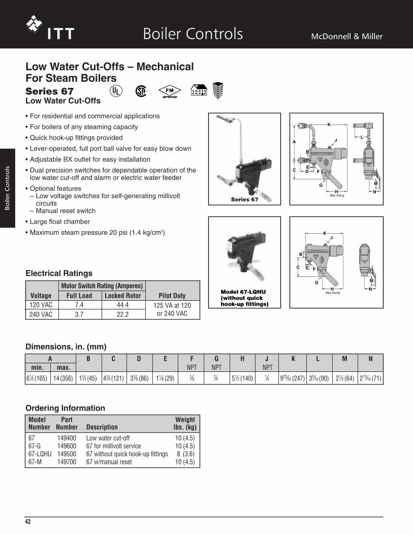
61⁄2 (165) 14 (356) 13⁄4 (45) 43⁄4 (121) 33⁄8 (86) 11⁄8 (29) 3⁄8 3⁄4 51⁄2 (140) 1⁄4 923⁄32 (247) 39⁄16 (90) 21⁄2 (64) 213⁄16 (71)
• For residential and commercial applications
• For boilers of any steaming capacity
• Quick hook-up fittings provided
• Lever-operated, full port ball valve for easy blow down
• Adjustable BX outlet for easy installation
• Dual precision switches for dependable operation of thelow water cut-off and alarm or electric water feeder
• Optional features– Low voltage switches for self-generating millivolt
circuits– Manual reset switch
• Large float chamber
• Maximum steam pressure 20 psi (1.4 kg/cm2)
Series 67
Model 67-LQHU(without quickhook-up fittings)
A
C D
B
EF
H
K
G
J
Max Swing
M
N
L
C
H
K
G
J
Max Swing
M
N
B
E F
Low Water Cut-Offs – MechanicalFor Steam BoilersSeries 67Low Water Cut-Offs
Dimensions, in. (mm)
Ordering InformationModel Part WeightNumber Number Description lbs. (kg)
67 149400 Low water cut-off 10 (4.5)67-G 149600 67 for millivolt service 10 (4.5)67-LQHU 149500 67 without quick hook-up fittings 8 (3.6)67-M 149700 67 w/manual reset 10 (4.5)
®
®
Electrical Ratings
Motor Switch Rating (Amperes)Voltage Full Load Locked Rotor Pilot Duty120 VAC 7.4 44.4 125 VA at 120240 VAC 3.7 22.2 or 240 VAC

A B C D E F G H J K L M N PNPT NPT NPT NPT NPT
15⁄32 (29.3) 313⁄32 (186.5) 3⁄8 3⁄8 3⁄4 213⁄16 (71) 53⁄8 (137) 21⁄2 1⁄4 23⁄64 (51.9) 35⁄8 (92) 85⁄32 (207) 911⁄16 (246.6) 51⁄2 (140)
• For residential and commercial low pressure boilerapplications
• For boilers of any steaming capacity
• 21⁄2" NPT body tapping for side mounting on boilers
• Lever-operated, full port ball valve for easy blow down
• Adjustable BX outlet for easy installation
• Dual precision switches for dependable operation of thelow water cut-off and alarm or electric water feeder
• Large float chamber
• Maximum steam pressure 20 psi (1.4 kg/cm2)Series 767
Series 767Low Water Cut-Offs
Dimensions, in. (mm)
N
E
D
C JAB
K
M
L
GPF
H
(Max. Swing)
Low Water Cut-Offs – MechanicalFor Steam Boilers
®
®
Ordering Information
Model Part WeightNumber Number Description lbs. (kg)
767 153700 Low water cut-off 8.5 (3.9)
Electrical Ratings
Motor Switch Rating (Amperes)Voltage Full Load Locked Rotor Pilot Duty120 VAC 7.4 44.4 125 VA at 120240 VAC 3.7 22.2 or 240 VAC
43
Boiler
Contro
ls
Boiler Controls McDonnell & Miller

44
Boile
rC
ontr
ols
Boiler Controls McDonnell & Miller
A B C D E F
InsertionModel Length NPT
69 41⁄8 (105)169 31⁄8 (79)269 21⁄4 (57) 1 (25) 41⁄8 (105) 1⁄8 (3) 21⁄2 91⁄2 (241)369 13⁄4 (45)
469, 569 13⁄16 (30)
• For residential and commercial low pressure steamboiler applications
• For boilers of any steaming capacity
• For mounting in 21⁄2" NPT boiler side tappings
• Insertion lengths available in 13⁄16 - 41⁄8" (30-105mm)
• Packless bellows
• Adjustable BX outlet for easy installation
• Dual precision switches for dependable operation of thelow water cut-off and an alarm or electric water feeder
• Optional low voltage switches for self-generating millivoltcircuits
• Maximum steam pressure 20 psi (1.4 kg/cm2)
Series 69
1 2
3 4D
CF
B E
CUT-OFF LEVEL
A
Low Water Cut-Offs – MechanicalFor Steam BoilersSeries 69Built-in Low Water Cut-Offs
Dimensions, in. (mm)
Ordering InformationModel Part WeightNumber Number Description lbs. (kg)
69 153900 Low water cut-off w/41⁄8" (105mm) 3.7 (1.7)insertion length
69-MV-P 155000 69 w/millivolt switch 4.0 (1.8)169 155100 69 w/31⁄8" (79mm) insertion length 4.0 (1.8)269 155200 69 w/21⁄4" (57mm) insertion length 4.0 (1.8)369 155300 69 w/13⁄4" (45mm) insertion length 4.0 (1.8)369-MV 155400 369 w/millivolt switch 4.0 (1.8)469 155500 69 w/13⁄16" (30mm) insertion length 4.0 (1.8)569 155700 469 w/13⁄16" (30mm) insertion length 4.0 (1.8)
w/1⁄4" NPT tapping
®
®
Electrical Ratings
Motor Switch Rating (Amperes)Voltage Full Load Locked Rotor Pilot Duty120 VAC 7.4 44.4 125 VA at 120240 VAC 3.7 22.2 or 240 VAC
45
Boiler
Contro
ls
Boiler Controls McDonnell & Miller
Model H J K L M N P Q R S TNPT NPT
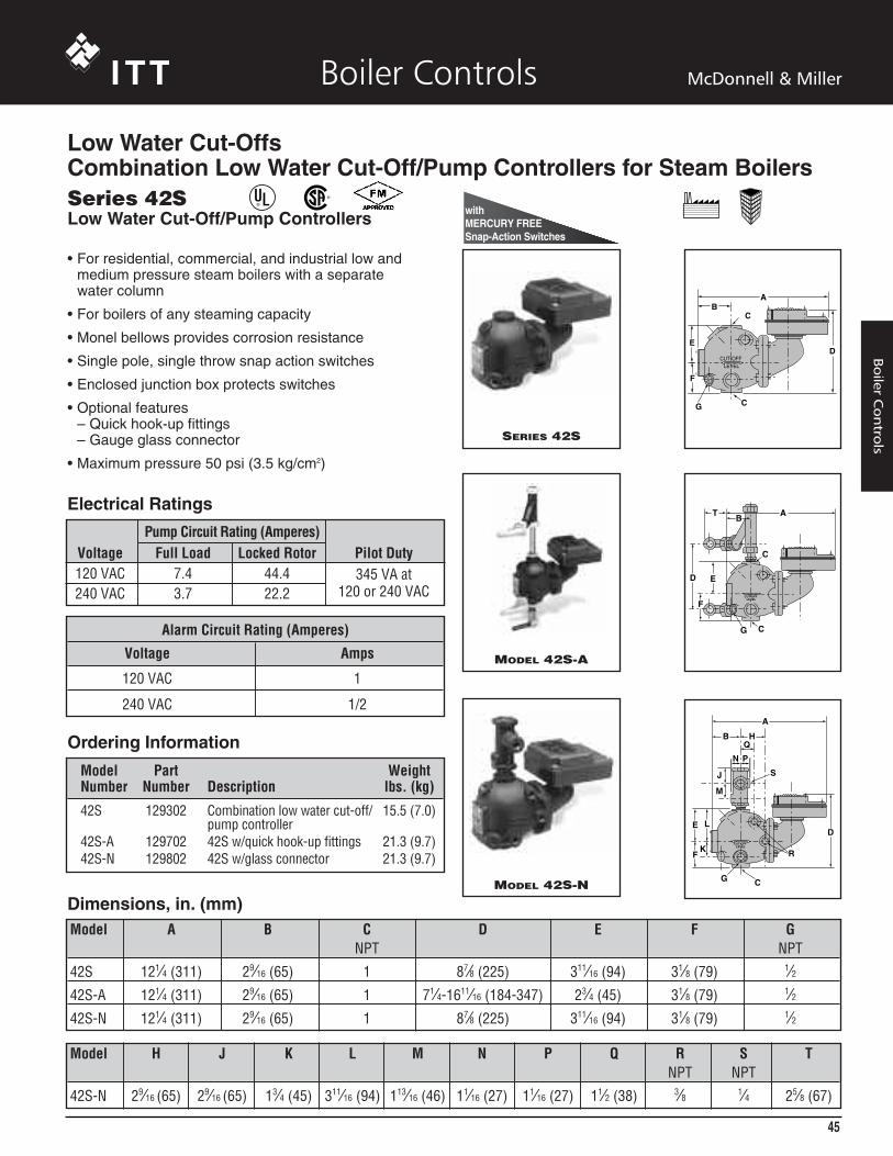
42S-N 29⁄16 (65) 29⁄16 (65) 13⁄4 (45) 311⁄16 (94) 113⁄16 (46) 11⁄16 (27) 11⁄16 (27) 11⁄2 (38) 3⁄8 1⁄4 25⁄8 (67)
Model A B C D E F GNPT NPT
42S 121⁄4 (311) 29⁄16 (65) 1 87⁄8 (225) 311⁄16 (94) 31⁄8 (79) 1⁄242S-A 121⁄4 (311) 29⁄16 (65) 1 71⁄4-1611⁄16 (184-347) 23⁄4 (45) 31⁄8 (79) 1⁄242S-N 121⁄4 (311) 29⁄16 (65) 1 87⁄8 (225) 311⁄16 (94) 31⁄8 (79) 1⁄2
B
DE
F
A
C
C
CUT-OFF LEVEL
G
• For residential, commercial, and industrial low andmedium pressure steam boilers with a separate water column
• For boilers of any steaming capacity
• Monel bellows provides corrosion resistance
• Single pole, single throw snap action switches
• Enclosed junction box protects switches
• Optional features– Quick hook-up fittings– Gauge glass connector
• Maximum pressure 50 psi (3.5 kg/cm2)
SERIES 42S
TB
F
ED
A
CG
C
CUT-OFF LEVEL
MODEL 42S-A
A
N
FK
M
J
LED
P
QB H
G C
R
S
CUT-OFF LEVEL
MODEL 42S-N
Dimensions, in. (mm)
Ordering Information
Series 42SLow Water Cut-Off/Pump Controllers
®
®
Model Part WeightNumber Number Description lbs. (kg)
42S 129302 Combination low water cut-off/ 15.5 (7.0)pump controller
42S-A 129702 42S w/quick hook-up fittings 21.3 (9.7)42S-N 129802 42S w/glass connector 21.3 (9.7)
Electrical Ratings
Pump Circuit Rating (Amperes)Voltage Full Load Locked Rotor Pilot Duty120 VAC 7.4 44.4 345 VA at240 VAC 3.7 22.2 120 or 240 VAC
Alarm Circuit Rating (Amperes)
Voltage Amps
120 VAC 1
240 VAC 1/2
withMERCURY FREESnap-Action Switches
Low Water Cut-OffsCombination Low Water Cut-Off/Pump Controllers for Steam Boilers
46
Boile
rC
ontr
ols
Boiler Controls McDonnell & Miller
E F G H J
35⁄16 (84) 915⁄16 (252) 41⁄8 (105) 37⁄16 (87) 1 NPT
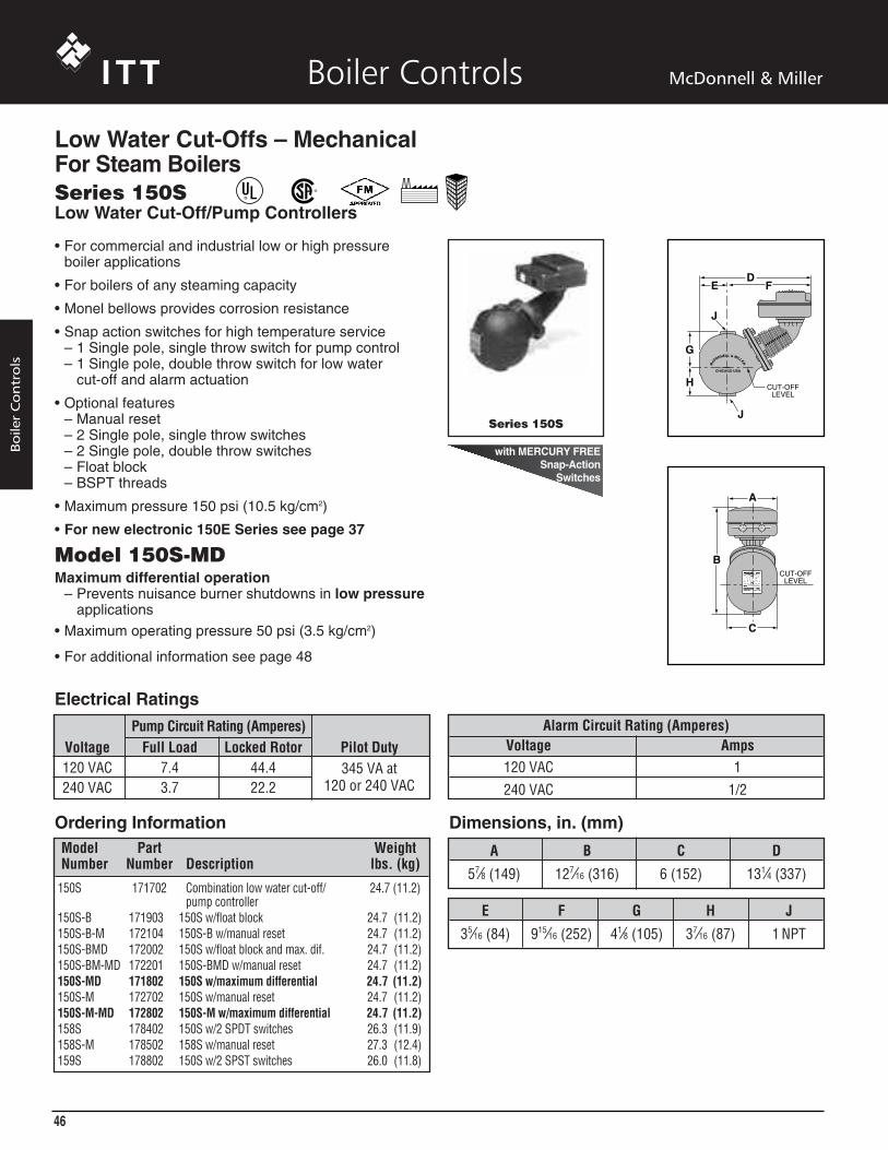
Series 150S
DE F
G
J
H
J
CUT-OFF LEVEL
A
B
C
CUT-OFF LEVEL
C
Dimensions, in. (mm)Ordering Information
Low Water Cut-Offs – MechanicalFor Steam Boilers
• For commercial and industrial low or high pressureboiler applications
• For boilers of any steaming capacity
• Monel bellows provides corrosion resistance
• Snap action switches for high temperature service– 1 Single pole, single throw switch for pump control– 1 Single pole, double throw switch for low water
cut-off and alarm actuation
• Optional features– Manual reset– 2 Single pole, single throw switches– 2 Single pole, double throw switches– Float block– BSPT threads
• Maximum pressure 150 psi (10.5 kg/cm2)
• For new electronic 150E Series see page 37
Model 150S-MDMaximum differential operation
– Prevents nuisance burner shutdowns in low pressureapplications
• Maximum operating pressure 50 psi (3.5 kg/cm2)
• For additional information see page 48
Series 150SLow Water Cut-Off/Pump Controllers
®
®
Model Part WeightNumber Number Description lbs. (kg)
150S 171702 Combination low water cut-off/ 24.7 (11.2)pump controller
150S-B 171903 150S w/float block 24.7 (11.2)150S-B-M 172104 150S-B w/manual reset 24.7 (11.2)150S-BMD 172002 150S w/float block and max. dif. 24.7 (11.2)150S-BM-MD 172201 150S-BMD w/manual reset 24.7 (11.2)150S-MD 171802 150S w/maximum differential 24.7 (11.2)150S-M 172702 150S w/manual reset 24.7 (11.2)150S-M-MD 172802 150S-M w/maximum differential 24.7 (11.2)158S 178402 150S w/2 SPDT switches 26.3 (11.9)158S-M 178502 158S w/manual reset 27.3 (12.4)159S 178802 150S w/2 SPST switches 26.0 (11.8)
A B C D
57⁄8 (149) 127⁄16 (316) 6 (152) 131⁄4 (337)
Electrical RatingsAlarm Circuit Rating (Amperes)
Voltage Amps120 VAC 1240 VAC 1/2
Pump Circuit Rating (Amperes)Voltage Full Load Locked Rotor Pilot Duty120 VAC 7.4 44.4 345 VA at240 VAC 3.7 22.2 120 or 240 VAC
with MERCURY FREESnap-Action
Switches

47
Boiler
Contro
ls
Boiler Controls McDonnell & Miller
Series 157S
Model 157S-R
GH
ED
J
C
F
J
K
A
B
L A
B
B
B
G
A
A
K
C
F
J
L
J
D
Series 157SLow Water Cut-Off/Pump Controllers
Low Water Cut-Offs – MechanicalFor Steam Boilers
®
®
• For residential, commercial and industrial low or highpressure boiler applications
• For boilers of any steaming capacity• Monel bellows provides corrosion resistance• Float chamber with integral water column provided•`Snap action for high temperature service
– 1 Single pole, single throw switch for pump control– 1 Single pole, double throw switch for low water
cut-off and alarm actuation• Optional features
– Manual reset– Integral conductance probes for additional levels and
greater operating differential-Model 157S-RBP-MD– 1" or 11⁄4" NPT equalizing tappings– 1⁄2" or 3⁄4" NPT tappings for gauge glass/tri-cock
installations– BSPT threads
• Maximum pressure 150 psi (10.5 kg/cm2)
• For new electronic 150E Series see page 37
Model 157S-MDMaximum differential operation
– Prevents nuisance burner shutdowns in low pressureapplications
– Maximum operating pressure 50 psi (3.5 kg/cm2)– For additional information see page 48
Dimensions, in. (mm)
Ordering Information
Alarm Circuit Rating (Amperes)
Voltage Amps
120 VAC 1
240 VAC 1/2
Electrical RatingsCut-off and Pump
Circuits Rating (Amperes)Voltage Full Load Locked Rotor Pilot Duty120 VAC 7.4 44.4 345 VA at240 VAC 3.7 22.2 120 or 240 VAC
Model Part WeightNumber Number Description lbs. (kg)157S 173502 150S low water cut-off w/water column 39.7 (18.0)157S-MD 173603 157S w/maximum differential 39.7 (18.0)157S-A 173702 157S w/alternate tappings 39.5 (17.9)157S-A-M 173802 157S-A w/manual reset 39.5 (17.9)157S-M 175402 157S w/manual reset 39.7 (18.0)157S-M-MD 175412 157S-M w/maximum differential 39.7 (18.0)157S-R 176220 157S w/alternate tappings 42.0 (19.0)157S-R-M 177306 157S-R w/manual reset 42.0 (19.0)157S-RBP-MD 176503 157S w/2 integral conductance probes 51.0 (23.1)157S-RL 176902 157S w/alternate tappings 42.0 (19.0)157S-RL-M 177006 157S-RL w/manual reset 42.0 (19.0)
Model A B C D E F G H J K LNPT NPT NPT
157S 1 1⁄2 133⁄8 (339) 25⁄16 (59) 415⁄16 (125) 113⁄4 (298) 16 (406) 111⁄2 (292) 31⁄2 (89) 3⁄4 57⁄8 (149)157S-A 11⁄4 3⁄4 133⁄8 (339) 25⁄16 (59) 415⁄16 (125) 113⁄4 (298) 16 (406) 111⁄2 (292) 31⁄2 (89) 3⁄4 57⁄8 (149)157S-R 1 1⁄2 133⁄8 (339) 21⁄4 (57) 57⁄8 (149) 113⁄4 (298) 17 (432) 111⁄2 (292) 31⁄2 (89) 3⁄4 61⁄4 (159)157S-RL 11⁄4 1⁄2 139⁄16 (345) 31⁄2 (89) 57⁄8 (149) 113⁄4 (298) 17 (432) 123⁄4 (324) 31⁄2 (89) 3⁄4 61⁄4 (159)

48
Boile
rC
ontr
ols
Boiler Controls McDonnell & Miller
The bellows on the 150 units are sensitive to pressure. At higher pressures the bellows is stiffer requiring moreforce to move it. At lower pressures the bellows is morepliable (less stiff) requiring less force to move it.Consequently, the on/off points tend to narrow at lowerpressures. (Less distance between on and off).
Early versions of the 150 units with mercury bulb switcheswere able to be adjusted. These units had knurledadjustment screws that could be used to raise, lower orwiden the setpoints. Although the available adjustmentwas small (usually 1⁄16" to 1⁄8 " total), it was enough tocompensate in the field for lower pressure systems.
Later versions of the 150 with mercury bulb switches andall snap switch units are not adjustable in the field. The‘MD’ models were created to provide a 150 control withfactory settings to compensate for the narrowing ofsetpoints on new and existing installations.
MD Model Setpoints
PUMP OFFPUMP ON
Switch setpoints at 150psi
3/4" Differential
113/16" Differential13/8" DifferentialBurner
Off BurnerOff
Standard Models "MD" Models
Operating LevelsSeries 150/157 & Series 150S/157S
On ‘MD’ models the distance between pump off andburner off is increased by approximately 7⁄16 ". Note that thepump on/off differential on both standard and ‘MD’ modelsis set at 3⁄4".
This larger differential is accomplished by lowering theburner off setpoint 3⁄8 " below the casting line on ‘MD’models when setting the burner on/off points at 150 psi.This compensates for the narrowing of the setpoints atlower operating pressures because the burner off point willmove upward (closer to the casting line) at lower pressures.

49
Boiler
Contro
ls
Boiler Controls McDonnell & Miller
Larger LWCO/Pump controller units are installed onequalizing lines. The piping must be full size and includecross connections where pipes change direction. Eachcontrol should include its own blow down piping andvalves.
These controls should be blown down daily when installedon commercial/industrial boilers and weekly in residentialapplications. Regular blow down keeps the control free ofsediment and ensures it operates properly.
When blowing down a control at pressure, the blow downvalve should be opened slowly. The piping needs to bewarmed up and stagnant water in the drain piping needsto be pushed out. Suddenly opening a blow down valvecauses steam to condense, which creates water hammer.Crushed floats and damaged linkages can occur whenwater hammer occurs due to improper blow down piping.
For these reasons, McDonnell & Miller recommends adual valve blow-down system for each control.
Proper Blow-down Procedure: (Using dual valve system)
1. With water in the boiler at its normal level, open“Positive Shut-off Ball Valve”.
2. Open “Throttling Gate Valve” slowly until drain pipingheats up and then open fully. Observe that the waterlevel starts falling in the gauge glass.
3. Close “Throttling Gate Valve” after verifying that thepump contacts have closed and the burner contactshave opened thus shutting down the boiler.
Note: If this does not happen, immediately close allvalves, turn off burner and correct the problem.
4. Close “Positive Shut-off Ball Valve”.
5. Observe that the water level returns to its normal levelbefore leaving site.
Blow Down Piping
SERIES 150S, 150E ANDSERIES 93/94 CONTROLS
Connecting lines to boilershould be straight runs
Positive Shutoff Valve(Ball Valve)
Slow Opening Valve"Throttling Valve"
(Gate Valve)
Piping must be pitched to drain with no restrictions or
reduction in pipe size
Recommended Dual Valve Blow-Down Piping

50
Boiler Controls McDonnell & Miller
• For commercial and industrial low or high pressuresteam boilers
• Maintains consistent water level regardless of pressure
• For boilers of any steaming capacity
• No. 5 Switch included
• Magnetic repulsion eliminates need for bellows
• Optional features
–Manual reset
• 7B switch (135ohm proportional control signal) tomaintain constant boiler water level
• 1" NPT connections
• Maximum pressure 150 psi (10.5 kg/cm2)
SERIES 93
O rdering Info r m a t i o nModel Part WeightNumber Number Description lbs. (kg)9 3 1 6 2 3 0 0 Combination low water cut-off/ 35.0 (15.9)
pump controller w/No. 5 switch9 3 - M 1 6 2 5 0 0 93 w/manual reset 35.0 (15.9)9 3 - 7 B 1 6 3 0 0 0 93 w/No. 7B switch 35.5 (16.0)9 3 - 7 B - M 1 6 3 1 0 0 93-7B W/manual reset 35.5 (16.0)
Dimensions, in. (mm)A B C D E F G H
NPT NPT3⁄4 1 101⁄16 (256) 185⁄8 (473) 519⁄32 (142) 415⁄32 (113.5) 87⁄8 (225) 127⁄8 (327)
Series 93Low Water Cut-Off/Pump Controllers
Electrical Ratings345 VA at 120 or 240 VAC
L ow Water Cut-Offs – Mech a n i c a lCombination Low Water Cut-Off/Pump Contro l l e rs for Steam Boilers
06. HotWtrLwco 50-61• 3/6/07 12:44 PM Page 50
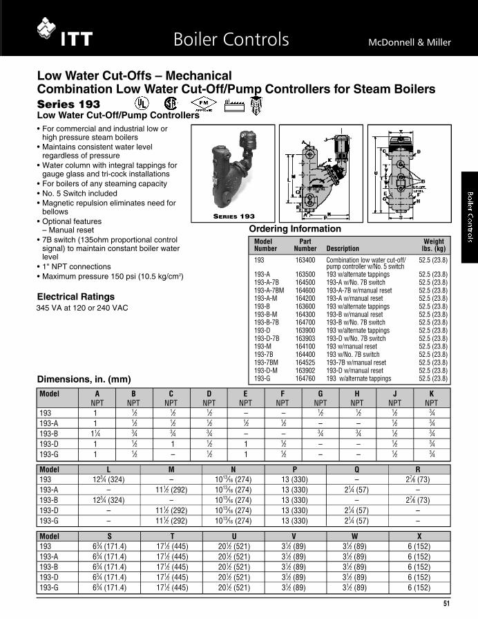
• For commercial and industrial low orhigh pressure steam boilers
• Maintains consistent water levelregardless of pressure
• Water column with integral tappings forgauge glass and tri-cock installations
• For boilers of any steaming capacity• No. 5 Switch included• Magnetic repulsion eliminates need for
bellows• Optional features
– Manual reset• 7B switch (135ohm proportional control
signal) to maintain constant boiler waterlevel
• 1" NPT connections• Maximum pressure 150 psi (10.5 kg/cm2)
SERIES 193
Series 193Low Water Cut-Off/Pump Controllers
Model S T U V W X193 63⁄4 (171.4) 171⁄2 (445) 201⁄2 (521) 31⁄2 (89) 31⁄2 (89) 6 (152)193-A 63⁄4 (171.4) 171⁄2 (445) 201⁄2 (521) 31⁄2 (89) 31⁄2 (89) 6 (152)193-B 63⁄4 (171.4) 171⁄2 (445) 201⁄2 (521) 31⁄2 (89) 31⁄2 (89) 6 (152)193-D 63⁄4 (171.4) 171⁄2 (445) 201⁄2 (521) 31⁄2 (89) 31⁄2 (89) 6 (152)193-G 63⁄4 (171.4) 171⁄2 (445) 201⁄2 (521) 31⁄2 (89) 31⁄2 (89) 6 (152)
Model L M N P Q R193 123⁄4 (324) – 1013⁄16 (274) 13 (330) – 27⁄8 (73)193-A – 111⁄2 (292) 1013⁄16 (274) 13 (330) 21⁄4 (57) –193-B 123⁄4 (324) – 1013⁄16 (274) 13 (330) – 27⁄8 (73)193-D – 111⁄2 (292) 1013⁄16 (274) 13 (330) 21⁄4 (57) –193-G – 111⁄2 (292) 1013⁄16 (274) 13 (330) 21⁄4 (57) –
Model A B C D E F G H J KNPT NPT NPT NPT NPT NPT NPT NPT NPT NPT
193 1 1⁄2 1⁄2 1⁄2 – – 1⁄2 1⁄2 1⁄2 3⁄4193-A 1 1⁄2 1⁄2 1⁄2 1⁄2 1⁄2 – – 1⁄2 3⁄4193-B 11⁄4 3⁄4 3⁄4 3⁄4 – – 3⁄4 3⁄4 1⁄2 3⁄4193-D 1 1⁄2 1 1⁄2 1 1⁄2 – – 1⁄2 3⁄4193-G 1 1⁄2 – 1⁄2 1 1⁄2 – – 1⁄2 3⁄4
Dimensions, in. (mm)
O rdering Info r m a t i o nModel Part WeightNumber Number Description lbs. (kg)1 9 3 1 6 3 4 0 0 Combination low water cut-off/ 52.5 (23.8)
pump controller w/No. 5 switch1 9 3 - A 1 6 3 5 0 0 193 w/alternate tappings 52.5 (23.8)1 9 3 - A - 7 B 1 6 4 5 0 0 193-A w/No. 7B switch 52.5 (23.8)1 9 3 - A - 7 B M 1 6 4 6 0 0 193-A-7B w/manual reset 52.5 (23.8)1 9 3 - A - M 1 6 4 2 0 0 193-A w/manual reset 52.5 (23.8)1 9 3 - B 1 6 3 6 0 0 193 w/alternate tappings 52.5 (23.8)1 9 3 - B - M 1 6 4 3 0 0 193-B w/manual reset 52.5 (23.8)1 9 3 - B - 7 B 1 6 4 7 0 0 193-B w/No. 7B switch 52.5 (23.8)1 9 3 - D 1 6 3 9 0 0 193 w/alternate tappings 52.5 (23.8)1 9 3 - D - 7 B 1 6 3 9 0 3 193-D w/No. 7B switch 52.5 (23.8)1 9 3 - M 1 6 4 1 0 0 193 w/manual reset 52.5 (23.8)1 9 3 - 7 B 1 6 4 4 0 0 193 w/No. 7B switch 52.5 (23.8)1 9 3 - 7 B M 1 6 4 5 2 5 193-7B w/manual reset 52.5 (23.8)1 9 3 - D - M 1 6 3 9 0 2 193-D w/manual reset 52.5 (23.8)1 9 3 - G 1 6 4 7 6 0 193 w/alternate tappings 52.5 (23.8)
Electrical Ratings345 VA at 120 or 240 VAC
51
Boiler Controls McDonnell & Miller
L ow Water Cut-Offs – Mech a n i c a lCombination Low Water Cut-Off/Pump Contro l l e rs for Steam Boilers
06. HotWtrLwco 50-61• 3/6/07 12:44 PM Page 51

52
Boiler Controls McDonnell & Miller
Model A B C D94 6 (152) 7 (178) 109⁄16 (268) 1813⁄16 (478)94-A 6 (152) 7 (178) 109⁄16 (268) 1813⁄16 (478)
• For commercial and industrial low or high pressuresteam boilers
• Maintains consistent water level regardless of pressure
• For boilers of any steaming capacity
• No. 5 Switch included
• Magnetic repulsion eliminates need for bellows
• Optional features– Manual reset
• 7B switch (135ohm proportional control signal) tomaintain constant boiler water level
– BSPT threads
• 11⁄4" NPT connections
• Maximum pressure 250 psi (17.6 kg/cm2)
• Ten bolt flange
SERIES 94
O rdering Info r m a t i o n
Dimensions, in. (mm)
Model E F G H94 57⁄8 (149) 411⁄16 (119) 83⁄4 (222) 1 21 5⁄1 6 ( 3 2 8 . 6 )94-A 57⁄8 (149) 411⁄16 (119) 83⁄4 (222) 1 21 5⁄1 6 ( 3 2 8 . 6 )
Model J K L M NNPT NPT
94 1⁄2 (15) 11⁄4 11⁄4 – –94-A 1⁄2 (15) 11⁄4 11⁄4 21⁄16 (52) 11⁄4 (32)
Model Part WeightNumber Number Description lbs. (kg)9 4 1 6 5 2 0 0 Combination low water cut-off/ 52.5 (23.8)
pump controller w/No. 5 switch9 4 - A 1 6 5 5 0 0 94 w/alternate tappings 50.3 (22.8)9 4 - A M 1 6 5 8 0 0 94-A w/manual reset 50.3 (22.8)9 4 - A - 7 B 1 6 5 7 0 0 94-AM w/No. 7B switch 52.5 (23.8)9 4 - M 1 6 5 9 0 0 94 w/manual reset 52.5 (23.8)9 4 - 7 B 1 6 6 3 0 0 94 w/No. 7B switch 52.0 (23.6)
Series 94Low Water Cut-Off/Pump Controllers
Electrical Ratings345 VA at 120 or 240 VAC
L ow Water Cut-Offs – Mech a n i c a lCombination Low Water Cut-Off/Pump Contro l l e rs for Steam Boilers
06. HotWtrLwco 50-61• 3/6/07 12:44 PM Page 52
Model A B C D E F G H J KNPT NPT NPT NPT NPT NPT NPT NPT NPT NPT
194 11⁄4 1⁄2 1⁄2 1⁄2 1⁄2 1⁄2 – – 1⁄2 3⁄4194-A 11⁄4 1⁄2 1⁄2 1⁄2 – – 1⁄2 1⁄2 1⁄2 3⁄4194-B 11⁄4 3⁄4 3⁄4 3⁄4 – – 3⁄4 3⁄4 1⁄2 3⁄4
Model T U V W X Y194 171⁄4 (438) 201⁄2 (521) 3 (76) 3 (76) 6 (152) 1013⁄16 (274)194-A 171⁄4 (438) 201⁄2 (521) 3 (76) 3 (76) 6 (152) 1013⁄16 (274)194-B 171⁄4 (438) 201⁄2 (521) 3 (76) 3 (76) 6 (152) 1013⁄16 (274)
Model L M N P Q R S194 – 115⁄8 (295) 63⁄4 (171.4) 131⁄16 (332) 213⁄16 (71) 11⁄4 (32) 23⁄8 (60)194-A 127⁄8 (327) – 63⁄4 (171.4) 131⁄16 (332) 213⁄16 (71) 11⁄4 (32) 23⁄8 (60)194-B 127⁄8 (327) – 63⁄4 (171.4) 131⁄16 (332) 213⁄16 (71) 11⁄4 (32) 23⁄8 (60)
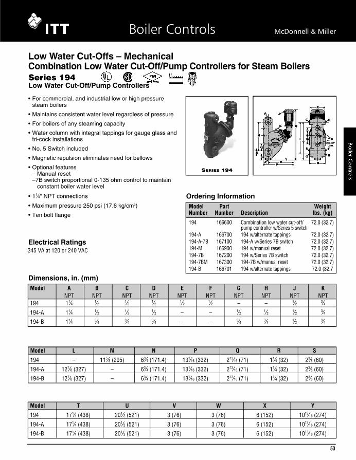
• For commercial, and industrial low or high pressuresteam boilers
• Maintains consistent water level regardless of pressure
• For boilers of any steaming capacity
• Water column with integral tappings for gauge glass andtri-cock installations
• No. 5 Switch included
• Magnetic repulsion eliminates need for bellows
• Optional features– Manual reset–7B switch proportional 0-135 ohm control to maintain
constant boiler water level
• 11⁄4" NPT connections
• Maximum pressure 250 psi (17.6 kg/cm2)
• Ten bolt flange
SERIES 194
L ow Water Cut-Offs – Mech a n i c a lCombination Low Water Cut-Off/Pump Contro l l e rs for Steam Boilers
O rdering Info r m a t i o nModel Part WeightNumber Number Description lbs. (kg)
1 9 4 1 6 6 6 0 0 Combination low water cut-off/ 72.0 (32.7)pump controller w/Series 5 switch
1 9 4 - A 1 6 6 7 0 0 194 w/alternate tappings 72.0 (32.7)1 9 4 - A - 7 B 1 6 7 1 0 0 194-A w/Series 7B switch 72.0 (32.7)1 9 4 - M 1 6 6 9 0 0 194 w/manual reset 72.0 (32.7)1 9 4 - 7 B 1 6 7 2 0 0 194 w/Series 7B switch 72.0 (32.7)1 9 4 - 7 B M 1 6 7 3 0 0 194-7B w/manual reset 72.0 (32.7)1 9 4 - B 1 6 6 7 0 1 194 w/alternate tappings 72.0 (32.7
Dimensions, in. (mm)
Series 194Low Water Cut-Off/Pump Controllers
Electrical Ratings345 VA at 120 or 240 VAC
Y
53
Boiler Controls McDonnell & Miller
06. HotWtrLwco 50-61• 3/6/07 12:44 PM Page 53

54
Boiler Controls McDonnell & Miller
A B C D E F G H J KNPT NPT
27⁄8 (73) 61⁄4 (159) 47⁄8 (124) 41⁄4 (108) 3⁄8 117⁄32 (39) 31⁄16 (78) 3⁄8 11⁄32 (26) 513⁄16 (148)
• For low pressure steam boilers with cold water feed
• Slide switch allows the timing cycle to be matched tothat of the boiler size and operation
• Electronic operation provides consistent, accurate cycle-to-cycle repeatability
• Universal design simplifies selection and reduces stock
• Can be used with mechanical or electronic low watercut-off controls
• Manual feed button
• Includes 3⁄8 NPT thread x 1⁄2" (13mm) tubing adapters forquick installation with 1⁄2" (13mm) copper tubing
• Easy to clean strainer
• Maximum water pressure 150 psi (10.5 kg/cm2)
• Maximum boiler pressure 15 psi (1 kg/cm2)
• Maximum water temperature 120°F (49°C)
• Maximum ambient temperature 100°F (38°C)
• Maximum power consumption (during water feed only)– 15 VA at 24 VAC– 20 VA at 120 VAC (50 or 60 Hz)
U n i - M a t c h
Water Feeders – Electric
O rdering Info r m a t i o n
Dimensions, in. (mm)
Model Part WeightNumber Number Description lbs. (kg)
W F - 2 - U - 2 4 1 6 9 5 5 0 Electric Water Feeder, 24V 2.8 (1.3)W F - 2 - U - 1 2 0 1 6 9 5 6 0 Electric Water Feeder, 120V 2.8 (1.3)
Series WF Uni-Match®
Electric Water Feeders
06. HotWtrLwco 50-61• 3/6/07 12:44 PM Page 54

A B C D E F G HNPT NPT
41⁄16 (103) 67⁄8 (175) 51⁄8 (130) 79⁄16 (192) 1⁄2 35⁄161⁄2 3 (76)
• For low pressure steam boilers with cold water feed
• Eliminates necessity to manually add water to the boiler
• Can be used with mechanical or electronic low watercut-off controls
• Quick-change replaceable cartridge valve and strainer
• Manual feed button
• Model 101-A features a 120 VAC solenoid
• Model 101-A-24 features a 24 VAC solenoid and aseparate 50VA transformer
• Maximum water supply pressure 150 psi (10.5 kg/cm2)
• Maximum boiler pressure 25 psi (1.8 kg/cm2)
• Maximum inlet water temperature 120°F (49°C)
• Maximum power consumption– 40 VA at 24 VAC– 40 VA at 120 VAC
Series 101-A
Water Feeders – Electric
Series 101-AElectric Water Feeders
O rdering Info r m a t i o n
Dimensions, in. (mm)
Model Part WeightNumber Number Description lbs. (kg)
1 0 1 A 1 6 9 4 0 0 Electric water feeder, 120V 2 . 8 ( 1 . 3 )1 0 1 A - 2 4 V 1 6 9 5 0 0 Electric water feeder, 24V 2 . 8 ( 1 . 3 )
F l ow DataPressure Differential Flow Rate
psi (kg/cm2) gpm (lpm)5 ( . 4 ) 1 . 4 ( 5 . 3 )
1 0 ( . 7 ) 1 . 7 ( 6 . 4 )2 0 ( 1 . 4 ) 2 . 1 ( 7 . 9 )4 0 ( 2 . 8 ) 2 . 9 ( 1 1 . 0 )6 0 ( 4 . 2 ) 3 . 4 ( 1 2 . 9 )8 0 ( 5 . 6 ) 4 . 0 ( 1 5 . 1 )
55
Boiler Controls McDonnell & Miller
06. HotWtrLwco 50-61• 3/6/07 12:44 PM Page 55

56
Boiler Controls McDonnell & Miller
H J K L M N PNPT
75⁄16 (186) 45⁄8 (117) 1⁄2 129⁄32 (58.4) 113⁄32 (35.7) 3 (76) 55⁄16 (135)
A B C D E F GNPT
117⁄8 (302) 51⁄4 (133) 73⁄8 (187) min. 25⁄8 (67) 3⁄4 51⁄8 (130) 105⁄8 (270)14 (356) max.
• For steam and hot water boilers with cold water feed
• Continuous maintenance of minimum safe water level,independent of electrical service
• Proportional feed action
• Quick hook-up fittings provided
• Quick-change replaceable cartridge valve and strainer
• Optional features– No. 2 switch– Manual reset
• Model 47 can be field upgraded with a No. 2 switch toadd low water cut-off function
• Maximum water supply pressure 150 psi (10.5 kg/cm2)
• Maximum inlet water temperature 120˚F (49˚C)
• Maximum boiler pressure 25 psi (1.8 kg/cm2)
Series 47
Series 47-2
Water Feeders – Mech a n i c a l
Series 47/47-2M e chanical Water Feeders / L ow Water Cut-Offs
Dimensions, in. (mm)
Electrical RatingsMotor Switch Rating (Amperes)
Voltage Full Load Locked Rotor Pilot Duty
120 VAC 10.2 61.2 125 VA at
240 VAC 5.1 30.6120 or 240 VAC
60 Hz
06. HotWtrLwco 50-61• 3/6/07 12:44 PM Page 56

Series 47 (continued)Mechanical Water Feeders
O rdering Info r m a t i o n
C a p a c i t i e s
Model Part WeightNumber Number Description lbs. (kg)
4 7 1 3 2 7 0 0 Mechanical water feeder 27.5 (12.5)4 7 - 2 1 3 2 8 0 0 47 w/No. 2 switch 28.5 (13.0)4 7 - 2 - M 1 3 2 9 0 0 47-2 w/manual reset 28.5 (13.0)4 7 - X 1 3 3 4 0 0 47 w/o quick hook-up fittings 25.0 (11.4)4 7 - 2 X 1 7 6 2 1 2 47-2 w/o quick hook-up fittings 26.0 (11.8)
Water Feeders – Mech a n i c a l
57
Boiler Controls McDonnell & Miller
06. HotWtrLwco 50-61• 3/6/07 12:44 PM Page 57
58
Boiler Controls McDonnell & Miller
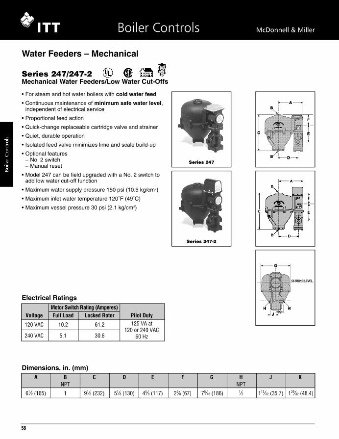
• For steam and hot water boilers with cold water feed
• Continuous maintenance of minimum safe water level,independent of electrical service
• Proportional feed action
• Quick-change replaceable cartridge valve and strainer
• Quiet, durable operation
• Isolated feed valve minimizes lime and scale build-up
• Optional features– No. 2 switch– Manual reset
• Model 247 can be field upgraded with a No. 2 switch toadd low water cut-off function
• Maximum water supply pressure 150 psi (10.5 kg/cm2)
• Maximum inlet water temperature 120˚F (49˚C)
• Maximum vessel pressure 30 psi (2.1 kg/cm2)
Series 247
Series 247-2
Water Feeders – Mech a n i c a l
Series 247/247-2Mechanical Water Feeders/Low Water Cut-Offs
Dimensions, in. (mm)A B C D E F G H J K
NPT NPT61⁄2 (165) 1 91⁄8 (232) 51⁄8 (130) 45⁄8 (117) 25⁄8 (67) 75⁄16 (186) 1⁄2 113⁄32 (35.7) 129⁄32 (48.4)
Electrical RatingsMotor Switch Rating (Amperes)
Voltage Full Load Locked Rotor Pilot Duty
120 VAC 10.2 61.2 125 VA at
240 VAC 5.1 30.6120 or 240 VAC
60 Hz
06. HotWtrLwco 50-61• 3/6/07 12:44 PM Page 58
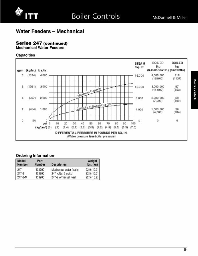
C a p a c i t i e s
Series 247 (continued)Mechanical Water Feeders
O rdering Info r m a t i o nModel Part WeightNumber Number Description lbs. (kg)2 4 7 1 3 3 7 0 0 Mechanical water feeder 22.0 (10.0)2 4 7 - 2 1 3 3 8 0 0 247 w/No. 2 switch 22.5 (10.2)2 4 7 - 2 - M 1 3 3 9 0 0 247-2 w/manual reset 22.5 (10.2)
Water Feeders – Mech a n i c a l
59
Boiler Controls McDonnell & Miller
06. HotWtrLwco 50-61• 3/6/07 12:44 PM Page 59

60
Boiler Controls McDonnell & Miller
O rdering Info r m a t i o n
• For low pressure steam and hot water boilers larger than5,000 sq. ft. (465m2) capacity with cold water feed
• Quick-change replaceable cartridge valve and strainer
• Optional features– No. 2 switch– Manual reset– Float block
• Proportional feed action
• Model 51 can be field upgraded with a No. 2 switch toadd low water cut-off function
• Maximum water supply pressure 150 psi (10.5 kg/cm2)
• Maximum inlet water temperature 120˚F (49˚C)
• Maximum vessel pressure 35 psi (2.5 kg/cm2)
Series 51
Series 51-2
Water Feeders – Mech a n i c a l
Series 51/51-2Mechanical Water Feeders/Low Water Cut-Offs
Dimensions, in. (mm)A B C D E F
NPT NPT NPT1 8 (203) 1 03⁄8 ( 2 6 4 ) 53⁄4 (146) 1 3⁄4
C a p a c i t i e s
Model Part WeightNumber Number Description lbs. (kg)
5 1 1 3 4 7 0 0 Mechanical water feeder 35.3 (16.0)5 1 - B 1 3 4 8 0 0 51 w/float block 38.5 (17.5)5 1 - B - 2 1 3 5 4 0 0 51-B w/Series 2 switch 38.3 (17.4)5 1 - B - 2 - M 1 3 5 5 0 0 51-B-2 w/manual reset 38.3 (17.4)5 1 - 2 1 3 5 0 0 0 51 w/Series 2 switch 35.8 (16.2)5 1 - 2 - M 1 3 5 2 0 0 51-2 w/manual reset 35.7 (16.2)
Electrical RatingsMotor Switch Rating (Amperes)
Voltage Full Load Locked Rotor Pilot Duty
120 VAC 10.2 61.2 125 VA at
240 VAC 5.1 30.6120 or 240 VAC
60 Hz
06. HotWtrLwco 50-61• 3/6/07 12:44 PM Page 60

O rdering Info r m a t i o n
• For high capacity [up to 35,000 sq. ft. (3250m2)] low pressuresteam and hot water boilers with cold water feed
• Optional features– No. 2 switch– Manual reset– Float block
• Proportional feed action
• Maximum water supply pressure 100 psi (7 kg/cm2)
• Maximum inlet water temperature 120˚F (49˚C)
• Maximum vessel pressure 35 psi (2.5 kg/cm2) Series 51-S
Series 51-S-2
Water Feeders – Mech a n i c a l
Series 51-S/51-S-2Mechanical Water Feeders/Low Water Cut-Offs
Dimensions, in. (mm)
Model Part WeightNumber Number Description lbs. (kg)51-S 135600 Mechanical water feeder 36.5 (16.6)51-S-2 135900 51-S w/No. 2 switch 37.3 (16.9)51-S-2-M 136000 51-S-2 w/manual reset 37.3 (16.9)51-SB 135700 51-S w/float block 41.8 (19.0)51-SB-2 136300 51-SB w/No. 2 switch 41.8 (19.0)51-SB-2-M 136100 51-SB-2 w/manual reset 43.7 (19.8)
A B C D E FNPT NPT NPT
1 81⁄8 (203) 1 03⁄8 ( 2 6 4 ) 53⁄4 (146) 1 3⁄4 C a p a c i t i e s
Electrical RatingsMotor Switch Rating (Amperes)
Voltage Full Load Locked Rotor Pilot Duty
120 VAC 10.2 61.2 125 VA at
240 VAC 5.1 30.6120 or 240 VAC
60 Hz
61
Boiler Controls McDonnell & Miller
06. HotWtrLwco 50-61• 3/7/07 12:45 PM Page 61

62
Boiler Controls McDonnell & Miller
Boile
rC
ontr
ols
C
D
BA
E
F
CLOSING LEVEL
C
D
BA
E
CLOSING LEVEL
F
A B C D E FNPT NPT NPT
1 81⁄8 (206) 103⁄8 (264) 53⁄4 (146) 1 3⁄4
Ordering Information
• For low pressure steam and hot water boilers larger than5,000 sq. ft. (465m2) with hot or cold water feed
• Optional features– No. 2 switch– Manual reset– Float block
• Proportional feed action
• Model 53 can be field upgraded with a No. 2 switch toadd low water cut-off function
• Maximum water supply pressure 150 psi (10.5 kg/cm2)
• Maximum inlet water temperature 120˚F (49˚C)
• Maximum vessel pressure 75 psi (5.3 kg/cm2)
Series 53
Series 53-2
Water Feeders – Mechanical
Series 53/53-2Mechanical Water Feeders/Low Water Cut-Offs
Dimensions, in. (mm)
Model Part WeightNumber Number Description lbs. (kg)
53 136900 Mechanical water feeder 38.0 (17.2)53-B 137400 53 w/float block 42.0 (19.0)53-B-2 137500 53-B w/No. 2 switch 42.0 (19.0)53-B-2-M 137600 53-B w/No. 2 switch & manual reset 42.0 (19.0)53-2 137100 53 w/No. 2 switch 38.5 (17.5)53-2-M 137200 53-2 w/manual reset 38.5 (17.5)
Capacity at Switch Cut-Off
Maximum Capacity
FEEDER DISCHARGE
DIFFERENTIAL PRESSURE IN POUNDS PER SQ. IN.(Water pressure less boiler pressure)
10,000
lbs./hr.
9,000
8,000
7,000
6,000
5,000
4,000
3,000
2,000
1,000
00psi 10 20 30 40 50 60 70 80 90 100
(0)(kg/cm2) (.7) (1.4) (2.1) (2.8) (3.5) (4.2) (4.9) (5.6) (6.3) (7.0)
(4536)
(kg/hr.)
STEAMSq.Ft.
BOILERhp
(Kilowatts)
40,000
36,000
32,000
28,000
24,000
20,000
16,000
12,000
8,000
4,000
0
290(2843)
261(2559)
232(2274)
203(1990)
174(1706)
145(1421)
116(1137)
87(853)
58(569)
29(284)
0
(4082)
(3629)
(3175)
(2722)
(2268)
(1814)
(1361)
(907)
(454)
(0)
20
gpm
18
16
14
12
10
8
6
4
2
0
®
®
Capacities
Electrical RatingsMotor Switch Rating (Amperes)
Voltage Full Load Locked Rotor Pilot Duty
120 VAC 10.2 61.2 125 VA at
240 VAC 5.1 30.6120 or 240 VAC
60 Hz

Model City Water Supply Pressure with 3/4" NPT Pipe and No Tank Pressure, 0 psi (kg/cm2)
Number 10 (.7) 20 (1.4) 30 (2.1) 40 (2.8) 50 (3.5) 60 (4.1) 70 (4.8) 80 (5.5) 90 (6.2)
25-A 3100 (1406) 4500 (2041) 5600 (2540) 6550 (2971) 7400 (3357) 8150 (3697) 8800 (3992) 9400 (4264) 10200 (4627)
21 & 221 4100 (1860) 6000 (2722) 7500 (3402) 8600 (3901) 9600 (4355) 10500 (4763) 11300 (5126) 12000 (5443) 13200 (5988)
847 1000 (454) 1500 (680) 1800 (816) 2100 (953) 2400 (1089) 2600 (1179) 2800 (1270) 3000 (1361) 3300 (1497)
851 2000 (907) 3000 (1361) 3700 (1678) 4300 (1850) 4800 (2177) — — — —
851-S 3000 (1361) 4000 (1814) 5000 (2268) 6200 (2812) — — — — —
551-S 2500 (1134) 3600 (1633) 4500 (2041) 5200 (2359) 5800 (2631) 6500 (2948) 7000 (3175) 7600 (3447) 8800 (3992)
Make-Up Water Feeders
In boiler feed systems with higher pressures, a make-upfeeder is usually provided on the condensate receiver. Itadds water to the receiver when necessary so there isalways an adequate supply for boiler demand.
ITT McDonnell & Miller Make-up feeders provide largefeeding capacity. Unless otherwise stated, valves andseats are of stainless steel and protected by a largeintegral strainer. Positive alignment of the valve isassured by cam & roller, straight thrust action. Thesefeeders can be used for many other liquid controlapplications such as:
• Pharmaceutical
• Laboratory
• Industrial
• Distillation equipment
• Receiver tanks
• Evaporative coolers
• Humidifiers
• Aquariums
• Steam baths
• Wet and dry hygrometers
Water Feeding Capacity lbs./hr. (kg/hr.)
63
Boiler Controls McDonnell & Miller
Boiler
Contro
ls

64
Boiler Controls McDonnell & Miller
Boile
rC
ontr
ols
• For boiler receiver tanks
• Float operated
• Proportional feed action
• Soft seat provides positive seal
• Seal between float chamber and valve chamber is not apositive seal
• Maximum water supply pressure 100 psi (7 kg/cm2)
• Maximum inlet water temperature 120˚F (49˚C)
• Maximum vessel pressure 35 psi (2.5 kg/cm2) Series 25-A
E
G
CD
AF
H
J
B
Water Feeders – Make-Up
Series 25-AMake-Up Water Feeder
Dimensions, in. (mm)
®
FEEDER DISCHARGE
WATER SUPPLY PRESSURE IN LBS. PER SQ. IN.
10,000
lbs./hr.
9,000
8,000
7,000
6,000
5,000
4,000
3,000
2,000
1,000
00psi 10 20 30 40 50 60 70 80 90 100
(0)(kg/cm2) (.7) (1.4) (2.1) (2.8) (3.5) (4.2) (4.9) (5.6) (6.3) (7.0)
(4536)
11,000(4990)
(kg/hr.)
(4082)
(3629)
(3175)
(2722)
(2268)
(1814)
(1361)
(907)
(454)
(0)
BOILER
22
20
18
16
14
12
10
8
6
4
2
0
(83.27)
(75.70)
(68.13)
(60.56)
(52.99)
(45.42)
(37.85)
(30.28)
(22.71)
(15.14)
(7.57)
(0)
gpm(lpm)
319
290
261
232
203
174
145
116
87
58
29
0
(3127)
(2843)
(2559)
(2274)
(1990)
(1706)
(1421)
(1137)
(853)
(569)
(284)
(0)
hp(Kilowatts)
Max
imum
Capacity
Capacities
Ordering InformationModel Part WeightNumber Number Description lbs. (kg)
25-A 126800 Make-up water feeder 37.5 (17)25-AB 126900 25-A w/float block 41.8 (19)
A B C D E F G H JNPT NPT NPT NPT
13⁄16 (21) 3⁄4 121⁄4 (311) 81⁄8 (206) 1 1⁄2 (12.7) 103⁄8 (264) 1 3⁄4

65
Boiler Controls McDonnell & Miller
Boiler
Contro
ls
A B C D E F G HNPT
81⁄2 (216) 35⁄16 (84) 55⁄8 (143) 813⁄16 (224) 43⁄4 (121) 61⁄4 (159) 3⁄4 73⁄8 (186)
• For boiler receiver tanks
• Direct mounting eliminates need for equalizingconnections
• Proportional feed action
• Mounting Flange – six 7⁄16" (11.1mm) bolt holes on a 53⁄4"(146mm) bolt circle
• Soft seat provides positive seal
• Maximum water supply pressure 150 psi (10.5 kg/cm2)
• Maximum inlet water temperature 120˚F (49˚C)
• Maximum vessel pressure 35 psi (2.5 kg/cm2)Series 21
CD
E
B
F AG
H
Water Feeders – Make-Up
Series 21Make-Up Water Feeder
Dimensions, in. (mm)
Series 221
Series 221Make-Up Water Feeder• For boiler receiver tanks• Direct mounting eliminates need for equalizing
connections• Proportional feed action
• Mounting Flange – six 17⁄32" (13.5mm) bolt holes on a 81⁄2"(216mm) bolt circle
• Soft seat provides positive seal• Maximum water supply pressure 150 psi (10.5 kg/cm2)• Maximum inlet water temperature 120˚F (49˚C)• Maximum vessel pressure 35 psi (2.5 kg/cm2)
Dimensions, in. (mm)
®
WATER SUPPLY PRESSURE IN LBS. PER SQ. IN.
CAPACITY CURVElbs./hr.
BOILER
psi
(kg/hr.)
1301201101009080706050403010
16,00015,00014,00013,00012,00011,00010,0009,0008,0007,0006,0005,0004,0003,0002,0001,000
0
(7258)(6804)(6350)(5897)(5443)(4990)(4536)(4082)(3629)(3175)(2722)(2268)(1814)(1361)(907)(454)
(0)
(0.7)(1.4)(2.1)(2.8)(3.5)(4.2)(4.9)(5.6)(6.3)(7.0)(7.7)(8.4)(9.1)(9.8)(10.5)
200
(0)
140 150
32302826242220181614121086420
(121.12)(113.55)(105.98)(98.41)(90.84)(83.27)(75.70)(68.13)(60.56)(52.99)(45.42)(37.85)(30.28)(22.71)(15.14)(7.57)(0)
(kg/cm2)
gpm(lpm)
4644354063773483192902612322031741451168758290
(4549)(4264)(3980)(3696)(3411)(3127)(2843)(2559)(2274)(1990)(1706)(1421)(1137)(853)(569)(284)(0)
hp(Kilowatts)
Capacities
H
CD
E
B
F AG
Ordering InformationModel Part WeightNumber Number Description lbs. (kg)
21 126400 Make-up water feeder 15.3 (6.9)221 126600 Make-up water feeder 21.3 (9.7)
A B C D E F G HNPT
81⁄2 (216) 411⁄16 (84) 55⁄8 (143) 813⁄16 (224) 43⁄4 (121) 61⁄4 (159) 3⁄4 (20) 91⁄2 (241)
66
Boiler Controls McDonnell & Miller
Boile
rC
ontr
ols
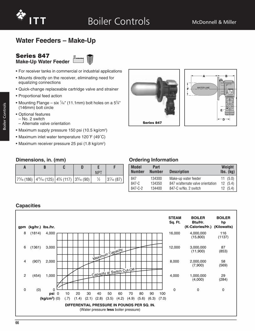
• For receiver tanks in commercial or industrial applications
• Mounts directly on the receiver, eliminating need forequalizing connections
• Quick-change replaceable cartridge valve and strainer
• Proportional feed action
• Mounting Flange – six 7⁄16" (11.1mm) bolt holes on a 53⁄4"(146mm) bolt circle
• Optional features– No. 2 switch– Alternate valve orientation
• Maximum supply pressure 150 psi (10.5 kg/cm2)
• Maximum inlet water temperature 120˚F (49˚C)
• Maximum receiver pressure 25 psi (1.8 kg/cm2)
Series 847Make-Up Water Feeder
Water Feeders – Make-Up
A B C D E FNPT
75⁄16 (186) 415⁄16 (125) 45⁄8 (117) 39⁄16 (90) 1⁄2 37⁄16 (87)
Dimensions, in. (mm)
Capacities
DIFFERENTIAL PRESSURE IN POUNDS PER SQ. IN.(Water pressure less boiler pressure)
4,000
lbs./hr.
BOILERBtu/Hr.
(K-Calories/Hr.)
4,000,000(15,800)
3,000,000(11,900)
2,000,000(7,900)
1,000,000(4,000)
116(1137)
87(853)
58(569)
29(284)
16,000
12,000
8,000
4,000
0 00
BOILERhp
(Kilowatts)
STEAMSq. Ft.
3,000
2,000
1,000
0psi
(1814)
(kg/hr.)
(1361)
(907)
(454)
(0)0 10 20 30 40 50 60 70 80 90 100
(kg/cm2) (0) (.7) (1.4) (2.1) (2.8) (3.5) (4.2) (4.9) (5.6) (6.3) (7.0)
Capacity at Switch Cut-Off
Maximum Capacity
8
gpm
6
4
2
0
Series 847
C
A B
D
E
F WATER LINE
Ordering InformationModel Part WeightNumber Number Description lbs. (kg)
847 134300 Make-up water feeder 11 (5.0)847-C 134350 847 w/alternate valve orientation 12 (5.4)847-C-2 134400 847-C w/No. 2 switch 12 (5.4)

67
Boiler Controls McDonnell & Miller
Boiler
Contro
ls
• For receiver tanks in commercial or industrialapplications
• Mounts directly on the receiver, eliminating need forequalizing connections
• Quick-change replaceable cartridge valve and strainer
• Proportional feed action
• Mounting Flange – six 7⁄16" (11.1mm) bolt holes on a 53⁄4"(146mm) bolt circle
• Maximum water supply pressure 150 psi (10.5 kg/cm2)
• Maximum inlet water temperature 120˚F (49˚C)
• Maximum receiver pressure 35 psi (2.5 kg/cm2)
Series 851Make-Up Water Feeder
Water Feeders – Make-Up
Series 851
A
WATER LINE
C
B
D
E
F
Model 851-S
C
F
A B
D
E
WATER LINE
Model 851-SMake-Up Water Feeder• Extended float and rod assembly
• Wider operating range
• Maximum water supply pressure 100 psi (7 kg/cm2)
• Maximum inlet water temperature 120˚F (49˚C)
• Maximum receiver pressure 35 psi (2.5 kg/cm2)
Dimensions, in. (mm)
Ordering Information
Model Part WeightNumber Number Description lbs. (kg)
851 136700 Make-up water feeder 14 (6.4)851-S 136800 851 w/extended float & rod assy. 16 (7.3)
Capacities – Model 851-S
FEEDER DISCHARGE
DIFFERENTIAL PRESSURE IN POUNDS PER SQ. IN.(Water pressure less boiler pressure)
10,000
lbs./hr.
9,000
8,000
7,000
6,000
5,000
4,000
3,000
2,000
1,000
00psi 10 20 30 40 50 60 70 80 90 100
(0)(kg/cm2) (.7) (1.4) (2.1) (2.8) (3.5) (4.2) (4.9) (5.6) (6.3) (7.0)
(4536)
(kg/hr.)
STEAMSq.Ft.
BOILERhp
(Kilowatts)
40,000
36,000
32,000
28,000
24,000
20,000
16,000
12,000
8,000
4,000
0
290(2843)
261(2559)
232(2274)
203(1990)
174(1706)
145(1421)
116(1137)
87(853)
58(569)
29(284)
0
(4082)
(3629)
(3175)
(2722)
(2268)
(1814)
(1361)
(907)
(454)
(0)
Max
imum
Capacity
Capacity at Switch Cut-Off
20
gpm
18
16
14
12
10
8
6
4
2
0
A B C D E FNPT
113⁄4 (298) 415⁄16 (125) 45⁄8 (117) 39⁄16 (90) 3⁄4 37⁄16 (87)
Capacities – Model 851
Capacity at Switch Cut-Off
Maximum Capacity
FEEDER DISCHARGE
DIFFERENTIAL PRESSURE IN POUNDS PER SQ. IN.(Water pressure less boiler pressure)
10,000
lbs./hr.
9,000
8,000
7,000
6,000
5,000
4,000
3,000
2,000
1,000
00psi 10 20 30 40 50 60 70 80 90 100
(0)(kg/cm2) (.7) (1.4) (2.1) (2.8) (3.5) (4.2) (4.9) (5.6) (6.3) (7.0)
(4536)
(kg/hr.)
STEAMSq.Ft.
BOILERhp
(Kilowatts)
40,000
36,000
32,000
28,000
24,000
20,000
16,000
12,000
8,000
4,000
0
290(2843)
261(2559)
232(2274)
203(1990)
174(1706)
145(1421)
116(1137)
87(853)
58(569)
29(284)
0
(4082)
(3629)
(3175)
(2722)
(2268)
(1814)
(1361)
(907)
(454)
(0)
20
gpm
18
16
14
12
10
8
6
4
2
0
Dimensions, in. (mm)A B C D E F
NPT
123⁄4 (324) 415⁄16 (125) 33⁄16 (81) 39⁄16 (90) 3⁄4 37⁄16 (87)

68
Boiler Controls McDonnell & Miller
Boile
rC
ontr
ols
Water Feeders – Make-Up
• For applications where water is added to steamseparators, receivers, tanks, or other vessels
• Proportional feed action
• Quick-change replaceable cartridge valve and strainer
• Optional features– Float Block
• Maximum water supply pressure 75 psi (5.3 kg/cm2)
• Maximum inlet water temperature 120˚F (49˚C)
• Maximum vessel pressure 25 psi (1.8 kg/cm2) 551-S
F
DE
H
C
B
GJ
A
CLOSING LEVEL
Series 551-SMake-Up Water Feeder
Dimensions, in. (mm)A B C D E F G H J
NPT NPT NPT
45⁄8 (117) 1⁄8 (3.2) 1 121⁄4 (311) 41⁄8 (105) 103⁄8 (264) 1 611⁄16 (170) 3⁄4
Ordering Information
Model Part WeightNumber Number Description lbs. (kg)
551-S 136400 Make-up water feeder 35.8 (16.2)551-SB 136500 551-S w/float block 35.8 (16.2)
FEEDER DISCHARGE
WATER SUPPLY PRESSURE IN LBS. PER SQ. IN.
(Available city water supply pressure, or pump pressure,less internal pressure of unit on which control is installed)
BOILER
lbs./hr.
7,000
6,000
5,000
4,000
3,000
2,000
1,000
00psi 10 20 30 40 50 60 70
(0)(kg/cm2) (.7) (1.4) (2.1) (2.8) (3.5) (4.2) (4.9)
(kg/hr.)gpm(lpm)
hp(Kilowatts)
14
12
10
8
6
4
2
0
(52.99) 203 (1990)
174 (1706)
145 (1421)
116 (1137)
87 (853)
58 (569)
29 (284)
0 (0)
(45.42)
(37.85)
(30.28)
(22.71)
(15.14)
(7.57)
(0)
(3175)
(2722)
(2268)
(1814)
(1361)
(907)
(454)
(0)
Max
imum
Capacity
Capacities

69
Boiler Controls McDonnell & Miller
Boiler
Contro
ls
• For McDonnell & Miller Series 47, 67 and 70B boilercontrol blow down valve replacement
• Full-ported ball action valve
• Teflon® seats provide bind free, leak tight ball movement
• Easy open handle keeps hands away from hot waterand steam
• Gasket and mounting screws included
• Maximum pressure 30 psi (1.8 kg/cm2)
• See page 127 for blow-down information
Series 14-B
Valves
Series 14-B Ball TypeBlow Down Valve F
EB
A
G
D
C90°
Ordering Information
Model Part WeightNumber Number Description lbs. (kg)
14-B 310447 Blow down valve 1 (.5)
Dimensions, in. (mm)A B C D E F G
NPT
63⁄4 (171.4) 4 (102) 21⁄4 (57) 3⁄4 21⁄2 (64) 21⁄2 (64) 53⁄4 (146)
• For hot water boilers
• Simplifies ASME CSD-1A. code mandated testing of lowwater cut-offs by eliminating the need to drain thesystem
• Includes one upper and one lower valve for mounting atcrosses in equalizing lines
• Restricts water flow when the low water cut-off’s blowdown valve is open
• Adjustable built-in vacuum breaker in upper valveprovides rapid evacuation of water from the floatchamber
• 1" NPT
• Maximum temperature 366°F (185°C)
• Maximum pressure 160 psi (11 kg/cm2)
Series TC-4Upper Valve
Series TC-4Test-N-Check® Valves
Ordering Information
Model Part WeightNumber Number Description lbs. (kg)
TC-4 195000 Test-N-Check Valves, set of 2 5.3 (.4)
®
®
A B C DNPT
1 11⁄2 (38) 11⁄2 (38) 5 (125)
Dimensions, in. (mm)
E F GNPT NPT Upper Lower
1 1 51⁄4 (133) 31⁄16 (78)
Series TC-4Lower Valve

70
McDonnell & Miller
• For tanks and hydronic heating systems
• Protects against over-pressure
• Minimizes hammering with flash steam
• Low differential pressure – 3 psi (.21 kg/cm2) betweenopening and closing
• Meets ASME Pressure Vessel and Boiler Code,Section IV
• Sizes and material– 3⁄4" - 1" NPT – bronze body and seat– 2" NPT – cast iron body, brass seat
• EPDM rubber diaphragm and seat disc
• Maximum temperature 250°F (121°C)
• Maximum operating pressure range30 - 125 psig (2.1 - 8.8 kg/cm2)
Series 2503/4" - 1" (20-25mm) NPT
Series 2502" (50mm) NPT
Va l v e s
Series 250Pressure Relief Valves
Size A B C D E FNPT
3⁄4 29⁄1 6 ( 6 5 ) 11⁄2 (38) 3⁄4 (20) 49⁄16 (116) 11⁄32 (26) 23⁄32 (53.2)1 27⁄8 ( 7 3 ) 13⁄4 (45) 7⁄8 (22) 415⁄16 (125) 11⁄32 (26) 21⁄4 (57)2 6 (152) 27⁄8 (73) 31⁄4 (83) 11 (279) — —
Dimensions, in. (mm)
• For water tanks and hydronic heating systems
• Protects against over-pressure
• Minimizes hammering with flash steam
• Low differential pressure – 3 psi (.21 kg/cm2) betweenopening and closing
• Meets ASME Pressure Vessel and Boiler Code,Section IV
• Sealed spring chamber prevents scale or sedimentbuild-up around seal
• 11⁄2" NPT Inlet and 2" NPT Discharge
• Cast iron body, brass seat
• Maximum temperature 250°F (121°C)
• Maximum operating pressure range30 - 50 psig (2.1 - 3.5 kg/cm2)
Series 260
Series 260Pressure Relief Valves
SizeNPT NPTInlet Outlet A B C D11⁄2 2 6 (152) 27⁄8 (73) 31⁄4 (83) 11 (279)
Dimensions, in. (mm)
Boiler Controls
08. Water Feeders 70-76• 3/6/07 1:48 PM Page 70

Va l v e s
Pe r fo r m a n c eModel Opening Pressure ASME RatingNumber psig (kg/cm2) BTUH (K-Calories)
2 5 0 - 3 / 4 I N - 1 5 1 5 ( 1 ) 5 1 5 , 0 0 0 ( 2 , 0 4 3 )2 5 0 - 3 / 4 I N - 3 0 3 0 ( 2 . 1 ) 7 9 0 , 0 0 0 ( 3 , 1 3 4 )2 5 0 - 3 / 4 I N - 3 6 3 6 ( 2 . 5 ) 9 0 0 , 0 0 0 ( 3 , 5 7 1 )2 5 0 - 3 / 4 I N - 4 0 4 0 ( 2 . 8 ) 9 7 3 , 0 0 0 ( 3 , 8 6 1 )2 5 0 - 3 / 4 I N - 4 5 4 5 ( 3 . 2 ) 1 , 0 6 5 , 0 0 0 ( 4 , 2 2 6 )2 5 0 - 3 / 4 I N - 5 0 5 0 ( 3 . 5 ) 1 , 1 6 0 , 0 0 0 ( 4 , 6 0 3 )2 5 0 - 3 / 4 I N - 6 0 6 0 ( 4 . 2 ) 1 , 2 5 2 , 0 0 0 ( 4 , 9 6 8 )2 5 0 - 3 / 4 I N - 7 5 7 5 ( 5 . 3 ) 1 , 6 1 5 , 0 0 0 ( 6 , 4 0 9 )2 5 0 - 3 / 4 I N - 1 0 0 1 0 0 ( 7 ) 2 , 0 7 5 , 0 0 0 ( 8 , 2 3 4 )2 5 0 - 3 / 4 I N - 1 2 5 1 2 5 ( 8 . 8 ) 2 , 5 3 5 , 0 0 0 ( 1 1 , 0 5 9 )2 5 0 - 1 I N - 1 5 1 5 ( 1 ) 7 7 0 , 0 0 0 ( 3 , 0 5 6 )2 5 0 - 1 I N - 3 0 3 0 ( 2 . 1 ) 1 , 1 7 0 , 0 0 0 ( 4 , 6 4 2 )2 5 0 - 1 I N - 3 6 3 6 ( 2 . 5 ) 1 , 3 3 0 , 0 0 0 ( 5 , 2 7 8 )2 5 0 - 1 I N - 4 0 4 0 ( 2 . 8 ) 1 , 4 3 7 , 0 0 0 ( 5 , 7 0 2 )2 5 0 - 1 I N - 4 5 4 5 ( 3 . 2 ) 1 , 5 7 5 , 0 0 0 ( 6 , 2 5 0 )2 5 0 - 1 I N - 5 0 5 0 ( 3 . 5 ) 1,710, 000 ( 6 , 7 8 6 )2 5 0 - 1 I N - 6 5 6 5 ( 4 . 6 ) 2 , 1 1 0 , 0 0 0 ( 8 , 3 7 3 )2 5 0 - 1 I N - 7 5 7 5 ( 5 . 3 ) 2 , 3 8 5 , 0 0 0 ( 9 , 4 6 4 )2 5 0 - 1 I N - 1 0 0 1 0 0 ( 7 ) 3 , 0 6 0 , 0 0 0 ( 1 2 , 1 4 2 )2 5 0 - 1 I N - 1 2 5 1 2 5 ( 8 . 8 ) 3 , 7 3 5 , 0 0 0 ( 1 4 , 8 2 1 )2 5 0 - 2 I N - 3 0 3 0 ( 2 . 1 ) 4 , 1 0 0 , 0 0 0 ( 1 6 , 2 7 0 )2 5 0 - 2 I N - 3 6 3 6 ( 2 . 5 ) 4 , 6 0 0 , 0 0 0 ( 1 8 , 2 5 4 )2 5 0 - 2 I N - 4 0 4 0 ( 2 . 8 ) 5 , 0 0 0 , 0 0 0 ( 1 9 , 8 4 1 )2 5 0 - 2 I N - 4 5 4 5 ( 3 . 2 ) 5 , 5 0 0 , 0 0 0 ( 2 1 , 8 2 5 )2 5 0 - 2 I N - 5 0 5 0 ( 3 . 5 ) 5 , 9 0 0 , 0 0 0 ( 2 3 , 4 1 2 )
O rdering Info r m a t i o nModel Part WeightNumber Number Description lbs. (kg)
2 5 0 - 3 / 4 I N - 1 5 1 8 1 2 2 0 Relief Valve 3⁄4 NPT, 15 psi (1 kg/cm2) 1 . 3 ( . 6 )2 5 0 - 3 / 4 I N - 3 0 1 8 1 2 2 5 Relief Valve 3⁄4 NPT, 30 psi (2.1 kg/cm2) 1 . 3 ( . 6 )2 5 0 - 3 / 4 I N - 3 6 1 8 1 3 2 5 Relief Valve 3⁄4 NPT, 36 psi (2.5 kg/cm2) 1 . 3 ( . 6 )2 5 0 - 3 / 4 I N - 4 0 1 8 1 4 0 5 Relief Valve 3⁄4 NPT, 40 psi (2.8 kg/cm2) 1 . 3 ( . 6 )2 5 0 - 3 / 4 I N - 4 5 1 8 1 4 2 5 Relief Valve 3⁄4 NPT, 45 psi (3.2 kg/cm2) 1 . 3 ( . 6 )2 5 0 - 3 / 4 I N - 5 0 1 8 1 5 2 5 Relief Valve 3⁄4 NPT, 50 psi (3.5 kg/cm2) 1 . 3 ( . 6 )2 5 0 - 3 / 4 I N - 6 0 1 8 1 9 0 5 Relief Valve 3⁄4 NPT, 60 psi (4.2 kg/cm2) 1 . 3 ( . 6 )2 5 0 - 3 / 4 I N - 7 5 1 8 1 6 2 5 Relief Valve 3⁄4 NPT, 75 psi (5.3 kg/cm2) 1 . 3 ( . 6 )2 5 0 - 3 / 4 I N - 1 0 0 1 8 1 7 2 5 Relief Valve 3⁄4 NPT, 100 psi (7 kg/cm2) 1 . 3 ( . 6 )2 5 0 - 3 / 4 I N - 1 2 5 1 8 1 8 2 5 Relief Valve 3⁄4 NPT, 125 psi (8.8 kg/cm2) 1 . 3 ( . 6 )2 5 0 - 1 I N - 1 5 1 8 1 9 2 0 Relief Valve 1 NPT, 15 psi (1 kg/cm2) 1 . 5 ( . 7 )2 5 0 - 1 I N - 3 0 1 8 1 9 2 5 Relief Valve 1 NPT, 30 psi (2.1 kg/cm2) 1 . 5 ( . 7 )2 5 0 - 1 I N - 3 6 1 8 2 0 2 5 Relief Valve 1 NPT, 36 psi (2.5 kg/cm2) 1 . 5 ( . 7 )2 5 0 - 1 I N - 4 0 1 8 2 0 3 0 Relief Valve 1 NPT, 40 psi (2.8 kg/cm2) 1 . 5 ( . 7 )2 5 0 - 1 I N - 4 5 1 8 2 1 2 5 Relief Valve 1 NPT, 45 psi (3.2 kg/cm2) 1 . 5 ( . 7 )2 5 0 - 1 I N - 5 0 1 8 2 2 2 5 Relief Valve 1 NPT, 50 psi (3.5 kg/cm2) 1 . 5 ( . 7 )2 5 0 - 1 I N - 6 5 1 8 2 2 3 5 Relief Valve 1 NPT, 65 psi (4.6 kg/cm2) 1 . 5 ( . 7 )2 5 0 - 1 I N - 7 5 1 8 2 3 2 5 Relief Valve 1 NPT, 75 psi (5.3 kg/cm2) 1 . 5 ( . 7 )2 5 0 - 1 I N - 1 0 0 1 8 2 4 2 5 Relief Valve 1 NPT, 100 psi (7 kg/cm2) 1 . 5 ( . 7 )2 5 0 - 1 I N - 1 2 5 1 8 2 5 2 5 Relief Valve 1 NPT, 125 psi (8.8 kg/cm2) 1 . 5 ( . 7 )2 5 0 - 2 I N - 3 0 1 8 3 0 2 5 Relief Valve 2 NPT, 30 psi (2.1 kg/cm2) 1 7 . 3 ( 7 . 8 )2 5 0 - 2 I N - 3 6 1 8 3 1 2 5 Relief Valve 2 NPT, 36 psi (2.5 kg/cm2) 1 7 . 3 ( 7 . 8 )2 5 0 - 2 I N - 4 0 1 8 3 1 7 5 Relief Valve 2 NPT, 40 psi (2.8 kg/cm2) 1 7 . 3 ( 7 . 8 )2 5 0 - 2 I N - 4 5 1 8 3 2 2 5 Relief Valve 2 NPT, 45 psi (3.2 kg/cm2) 1 7 . 3 ( 7 . 8 )2 5 0 - 2 I N - 5 0 1 8 3 3 2 5 Relief Valve 2 NPT, 50 psi (3.5 kg/cm2) 1 7 . 3 ( 7 . 8 )
Series 250Pressure Relief Valves
Pe r fo r m a n c eModel Opening Pressure ASME RatingNumber psig (kg/cm2) BTUH (K-Calories)
260-1 1/2IN-30 3 0 ( 2 . 1 ) 3 , 3 0 0 , 0 0 0 ( 1 3 , 0 9 5 )260-1 1/2IN-36 3 6 ( 2 . 5 ) 3 , 8 0 0 , 0 0 0 ( 1 5 , 0 7 9 )260-1 1/2IN-40 4 0 ( 2 . 8 ) 4 , 1 0 0 , 0 0 0 ( 1 6 , 2 7 0 )260-1 1/2IN-45 4 5 ( 3 . 2 ) 4 , 5 0 0 , 0 0 0 ( 1 7 , 8 5 7 )260-1 1/2IN-50 5 0 ( 3 . 5 ) 4 , 9 0 0 , 0 0 0 ( 1 9 , 4 4 4 )
O rdering Info r m a t i o nModel Part WeightNumber Number Description lbs. (kg)
260-1 1/2IN-30 1 8 2 6 2 5 Relief Valve 11⁄2 NPT, 30 psi (2.1 kg/cm2) 1 7 . 3 ( 7 . 8 )260-1 1/2IN-36 1 8 2 7 2 5 Relief Valve 11⁄2 NPT, 36 psi (2.5 kg/cm2) 1 7 . 3 ( 7 . 8 )260-1 1/2IN-40 1 8 2 7 3 0 Relief Valve 11⁄2 NPT, 40 psi (2.8 kg/cm2) 1 7 . 3 ( 7 . 8 )260-1 1/2IN-45 1 8 2 8 2 5 Relief Valve 11⁄2 NPT, 45 psi (3.2 kg/cm2) 1 7 . 3 ( 7 . 8 )260-1 1/2IN-50 1 8 2 9 2 5 Relief Valve 11⁄2 NPT, 50 psi (3.5 kg/cm2) 1 7 . 3 ( 7 . 8 )
71
BOILER CONTROLS
Boiler Controls McDonnell & Miller
Series 260Pressure Relief Valves
08. Water Feeders 70-76• 3/6/07 1:48 PM Page 71