
Boat Lifts and Docks
30
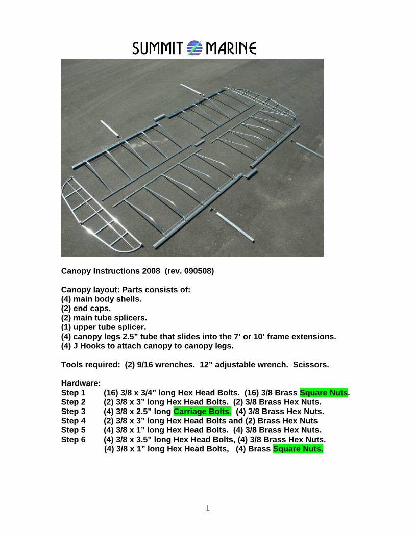
Canopy Instructions 2008 (rev. 090508) Canopy layout: Parts consists of: (4) main body shells. (2) end caps. (2) main tube splicers. (1) upper tube splicer. (4) canopy legs 2.5” tube that slides into the 7’ or 10’ frame extensions. (4) J Hooks to attach canopy to canopy legs. Tools required: (2) 9/16 wrenches. 12” adjustable wrench. Scissors. Hardware: Step 1 (16) 3/8 x 3/4” long Hex Head Bolts. (16) 3/8 Brass Square Nuts. Step 2 (2) 3/8 x 3” long Hex Head Bolts. (2) 3/8 Brass Hex Nuts. Step 3 (4) 3/8 x 2.5” long Carriage Bolts. (4) 3/8 Brass Hex Nuts. Step 4 (2) 3/8 x 3” long Hex Head Bolts and (2) Brass Hex Nuts Step 5 (4) 3/8 x 1” long Hex Head Bolts. (4) 3/8 Brass Hex Nuts. Step 6 (4) 3/8 x 3.5” long Hex Head Bolts, (4) 3/8 Brass Hex Nuts. (4) 3/8 x 1” long Hex Head Bolts, (4) Brass Square Nuts. 1
Transcript of Boat Lifts and Docks
Canopy Instructions 2008 (rev. 090508) Canopy layout: Parts consists of: (4) main body shells. (2) end caps. (2) main tube splicers. (1) upper tube splicer. (4) canopy legs 2.5” tube that slides into the 7’ or 10’ frame extensions. (4) J Hooks to attach canopy to canopy legs. Tools required: (2) 9/16 wrenches. 12” adjustable wrench. Scissors. Hardware: Step 1 (16) 3/8 x 3/4” long Hex Head Bolts. (16) 3/8 Brass Square Nuts. Step 2 (2) 3/8 x 3” long Hex Head Bolts. (2) 3/8 Brass Hex Nuts. Step 3 (4) 3/8 x 2.5” long Carriage Bolts. (4) 3/8 Brass Hex Nuts. Step 4 (2) 3/8 x 3” long Hex Head Bolts and (2) Brass Hex Nuts Step 5 (4) 3/8 x 1” long Hex Head Bolts. (4) 3/8 Brass Hex Nuts. Step 6 (4) 3/8 x 3.5” long Hex Head Bolts, (4) 3/8 Brass Hex Nuts. (4) 3/8 x 1” long Hex Head Bolts, (4) Brass Square Nuts.
1
2
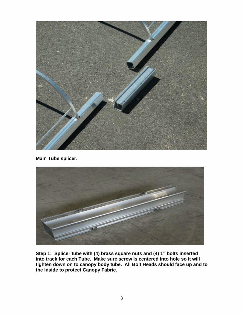
Main Tube splicer.
Step 1: Splicer tube with (4) brass square nuts and (4) 1” bolts inserted into track for each Tube. Make sure screw is centered into hole so it will tighten down on to canopy body tube. All Bolt Heads should face up and to the inside to protect Canopy Fabric.
3

Step 2: Upper Tube Splicer. (2) 3/8 x 3” Hex Head Bolts and (2) 3/8 Brass Hex Nuts. This Splicer Channel is packaged in the Splicer Tube.
4

Step 3: Attach Main Body Tubes. (4) 3/8 x 2.5” long Carriage Bolts. (4) 3/8 Brass Hex Nuts.
5

6

Step 4: Slide End Caps onto Main Body. (2) 3/8 x 3” long Hex Head Bolts and (2) Brass Hex Nuts to secure End Cap to Main Canopy Frame at the top.
7

Step 5: (4) 3/8 x 1” long Hex Head Bolts. (4) 3/8 Brass Hex Nuts. Bolt the End Cap to the Main Body as shown.
8

9
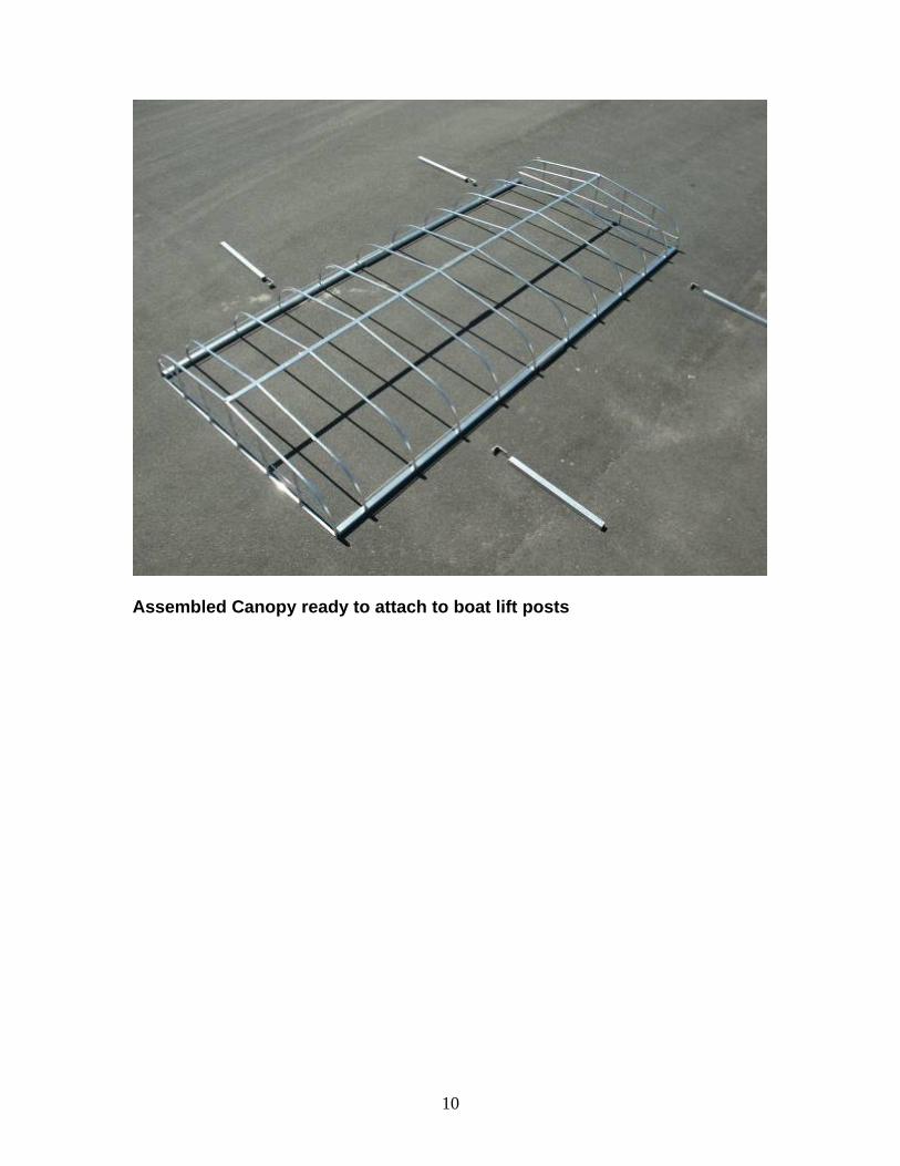
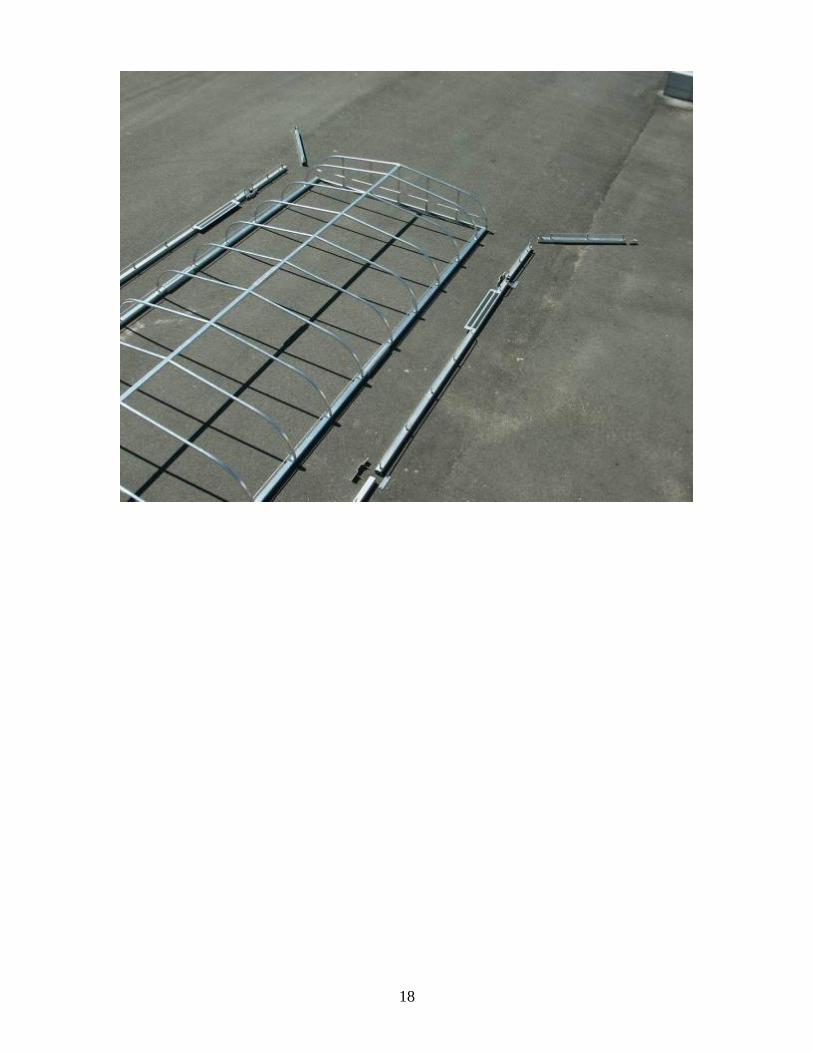
Assembled Canopy ready to attach to boat lift posts
10
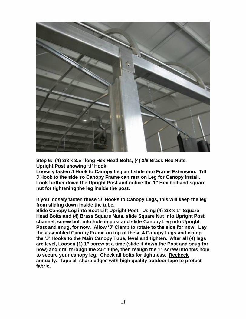
Step 6: (4) 3/8 x 3.5” long Hex Head Bolts, (4) 3/8 Brass Hex Nuts. Upright Post showing ‘J’ Hook. Loosely fasten J Hook to Canopy Leg and slide into Frame Extension. Tilt J Hook to the side so Canopy Frame can rest on Leg for Canopy install. Look further down the Upright Post and notice the 1” Hex bolt and square nut for tightening the leg inside the post. If you loosely fasten these ‘J’ Hooks to Canopy Legs, this will keep the leg from sliding down inside the tube. Slide Canopy Leg into Boat Lift Upright Post. Using (4) 3/8 x 1” Square Head Bolts and (4) Brass Square Nuts, slide Square Nut into Upright Post channel, screw bolt into hole in post and slide Canopy Leg into Upright Post and snug, for now. Allow ‘J’ Clamp to rotate to the side for now. Lay the assembled Canopy Frame on top of these 4 Canopy Legs and clamp the ‘J’ Hooks to the Main Canopy Tube, level and tighten. After all (4) legs are level, Loosen (1) 1” screw at a time (slide it down the Post and snug for now) and drill through the 2.5” tube, then realign the 1” screw into this hole to secure your canopy leg. Check all bolts for tightness. Recheck annually. Tape all sharp edges with high quality outdoor tape to protect fabric.
11

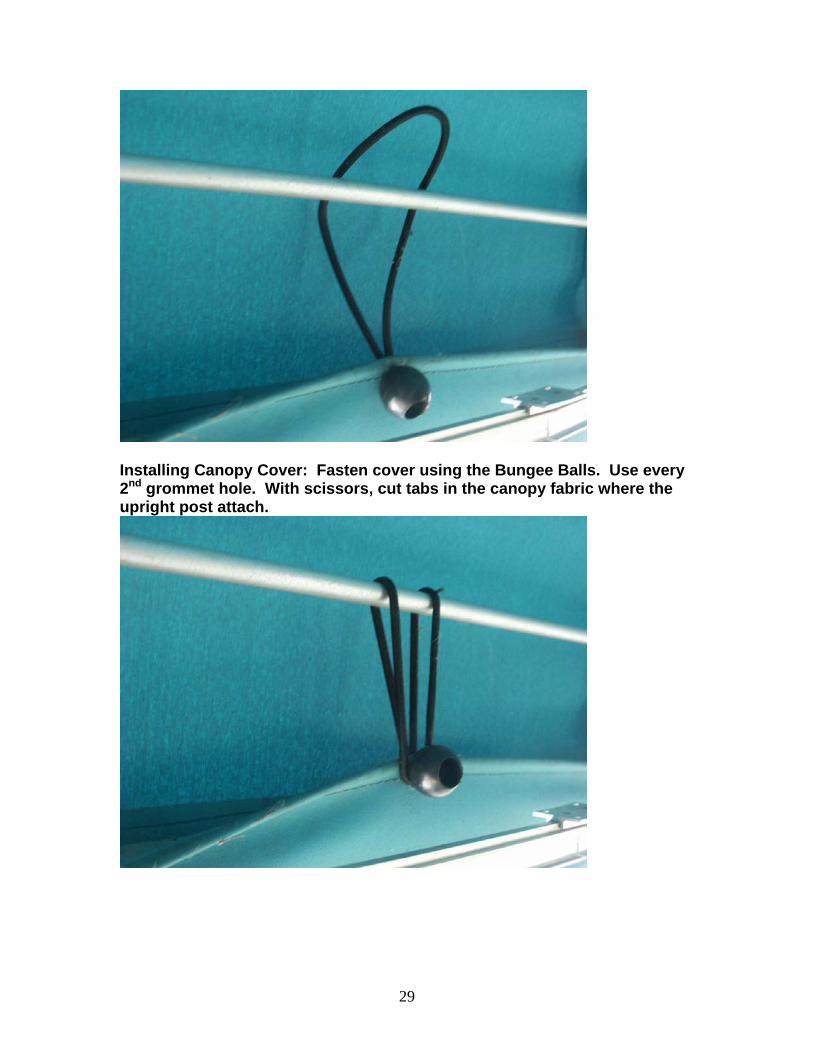
Installing Canopy Cover: Fasten cover using the Bungee Balls. Use every 2nd grommet hole. With scissors, cut tabs in the canopy fabric where the upright post attach.
12

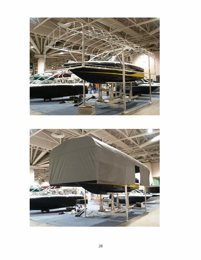
TOWER CANOPY - BEFORE PROCEEDING – Add Clamp Plate to Post as shown on the following page. Then, build and fasten canopy to boat lift, as described in the preceding pages, adjust height, and position rear of canopy 50.5” from rear post. Make sure you are satisfied with the canopy position before adding the tower. Excess weight and clamps will make it harder to adjust later. (REV. 072308.)
Tower Canopy: Consists of the following: (1) Front Cross Tube. (2) Front Side Tubes – non handed. (2) Middle Side Tubes LH/RH. (2) Rear Side Tubes. (2) Front Upright Posts LH/RH. These connect to the canopy frame via J Hook and hold the Front Cross Tube and the Front Side Tubes in position. (2) Rear Upright Posts LH/RH. These connect to the canopy frame via J Hook and hold the Rear Side Tubes only. There is no Back Cross Tube because the boat enters from this side. (4) Clamp Brackets and Clamp Plates. (4) J Hooks. (18) 3/8 x 3.5” hex head bolt. (18) 3/8 brass nuts. Tools Needed: 2 - 9/16 wrenches, 12” adjustable wrench, Hack Saw, and Tape measure
13

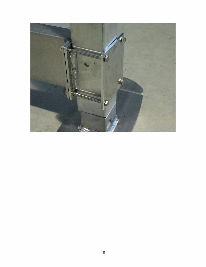
TOWER CANOPY POST CLAMP: Add Post Clamps to Beams as shown. Upright Post currently. Remove (2) top screws first (leave bottom screws tight).
Install Clamp Plate and tighten these top screws. Then repeat for bottom screws. This will hold Post to beam without removing it from lift.
Upright Post with new clamp bracket.
14
15
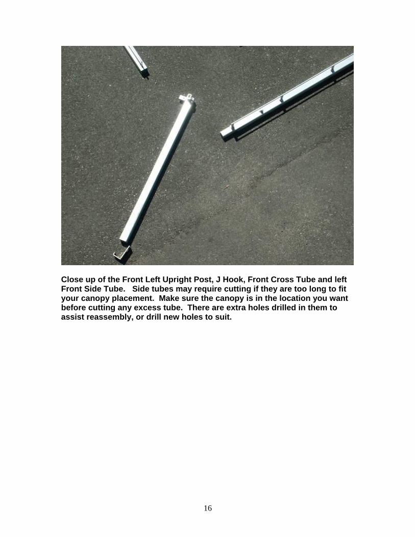
Close up of the Front Left Upright Post, J Hook, Front Cross Tube and left Front Side Tube. Side tubes may require cutting if they are too long to fit your canopy placement. Make sure the canopy is in the location you want before cutting any excess tube. There are extra holes drilled in them to assist reassembly, or drill new holes to suit.
16

Close up of Clamp Bracket and Clamp Plate.
17
18

Summit Marine Tower Frame adaptor tube:
Contents: 2 splicer tubes 2x2 x 57” long. 4 bolts 3/8 x 3” long. Add this tube to either end of the middle section of the tower frame, the tube with the step on it. Slide the end of the tube without holes in it into the step tube. This will give you 24” of the smaller tube extending out.
19

Step Tube shown at top of picture, Extension Tube shown inside Step Tube with post brackets attached at bottom of picture.
20
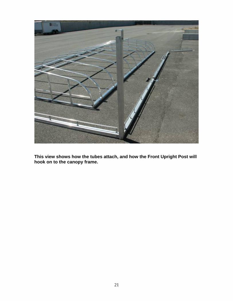
This view shows how the tubes attach, and how the Front Upright Post will hook on to the canopy frame.
21
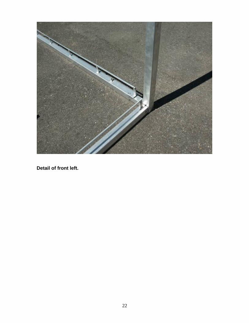
Detail of front left.
22

Detail of J Hook – notched to clear Canopy End Cap. This J Hook will fasten to the canopy frame and support the tower tube frame.
23

Front right detail.
24

Rear left detail.
25
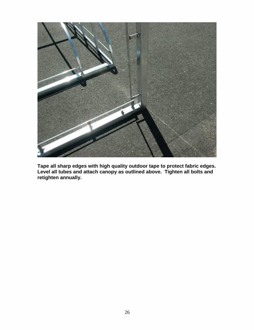
Tape all sharp edges with high quality outdoor tape to protect fabric edges. Level all tubes and attach canopy as outlined above. Tighten all bolts and retighten annually.
26

27
28
Installing Canopy Cover: Fasten cover using the Bungee Balls. Use every 2nd grommet hole. With scissors, cut tabs in the canopy fabric where the upright post attach.
29
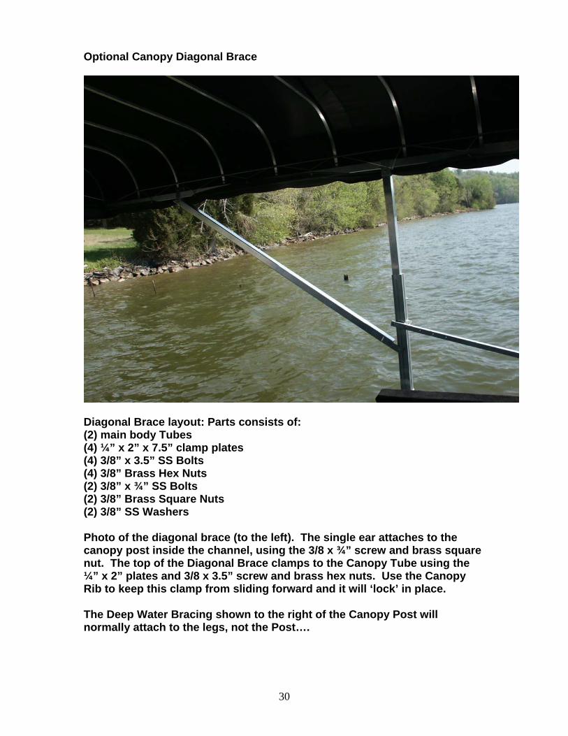
Optional Canopy Diagonal Brace
Diagonal Brace layout: Parts consists of: (2) main body Tubes (4) ¼” x 2” x 7.5” clamp plates (4) 3/8” x 3.5” SS Bolts (4) 3/8” Brass Hex Nuts (2) 3/8” x ¾” SS Bolts (2) 3/8” Brass Square Nuts (2) 3/8” SS Washers Photo of the diagonal brace (to the left). The single ear attaches to the canopy post inside the channel, using the 3/8 x ¾” screw and brass square nut. The top of the Diagonal Brace clamps to the Canopy Tube using the ¼” x 2” plates and 3/8 x 3.5” screw and brass hex nuts. Use the Canopy Rib to keep this clamp from sliding forward and it will ‘lock’ in place. The Deep Water Bracing shown to the right of the Canopy Post will normally attach to the legs, not the Post….
30