Board-Mounted Electronic Component Transient Thermal Behavior: CFD ... · techniques, such as...
24
International Microelectronics And Packaging Society 27 The International Journal of Microcircuits and Electronic Packaging, Volume 25, Number 1, First Quarter, 2002 (ISSN 1063-1674) Board-Mounted Electronic Component Transient Thermal Behavior: CFD Prediction Versus Measurement Valérie Eveloy and Peter Rodgers Electronics Thermal Management Ltd., Upper Quay, Westport, Co. Mayo, Ireland. Email: [email protected] Internet: www.etmcooling.com Abstract Numerical predictive accuracy is investigated for transient component heat transfer using a Computational Fluid Dynamics (CFD) code dedicated to the thermal analysis of electronic equipment. The test cases are based on a single Printed Circuit Board (PCB)-mounted, 160-lead PQFP component, analyzed in still-air, and both 1 and 2.25 m/s forced airflows. Three types of transient operating conditions are considered, namely (i) component dynamic power dissipation in fixed ambient conditions, (ii) passive component operation in dynamic ambient conditions, and (iii) combined component dynamic power dissipation in varying ambient conditions. Benchmark criteria are based on component junction temperature and component-PCB surface temperature, measured using thermal test dies and infrared thermography respectively. Using both nominal component/PCB geometry dimensions and material properties, component junction temperature is found to be accurately predicted for component dynamic power dissipation, in both fixed and varying ambient air temperature conditions. The results suggest that CFD analysis could play an important role in providing critical boundary conditions for component electrical and thermo-mechanical behavior analyses. However, caution is stressed on the use of heat transfer predictions for multi-component board applications. Key Words CFD, component modeling, benchmark, electronics cooling, transient heat transfer, reliability. Nomenclature T temperature, ºC Subscripts a ambient j component junction
Transcript of Board-Mounted Electronic Component Transient Thermal Behavior: CFD ... · techniques, such as...
International Microelectronics And Packaging Society
27
The International Journal of Microcircuits and Electronic Packaging, Volume 25, Number 1, First Quarter, 2002 (ISSN 1063-1674)
Board-Mounted Electronic Component TransientThermal Behavior: CFD Prediction VersusMeasurement
Valérie Eveloy and Peter RodgersElectronics Thermal Management Ltd., Upper Quay, Westport,
Co. Mayo, Ireland.Email: [email protected] Internet: www.etmcooling.com
Abstract
Numerical predictive accuracy is investigated for transient component heat transfer using aComputational Fluid Dynamics (CFD) code dedicated to the thermal analysis of electronicequipment. The test cases are based on a single Printed Circuit Board (PCB)-mounted, 160-leadPQFP component, analyzed in still-air, and both 1 and 2.25 m/s forced airflows. Three types oftransient operating conditions are considered, namely (i) component dynamic power dissipationin fixed ambient conditions, (ii) passive component operation in dynamic ambient conditions, and(iii) combined component dynamic power dissipation in varying ambient conditions. Benchmarkcriteria are based on component junction temperature and component-PCB surface temperature,measured using thermal test dies and infrared thermography respectively.
Using both nominal component/PCB geometry dimensions and material properties, componentjunction temperature is found to be accurately predicted for component dynamic power dissipation,in both fixed and varying ambient air temperature conditions. The results suggest that CFD analysiscould play an important role in providing critical boundary conditions for component electrical andthermo-mechanical behavior analyses. However, caution is stressed on the use of heat transferpredictions for multi-component board applications.
Key Words
CFD, component modeling, benchmark,electronics cooling, transient heat transfer,reliability.
Nomenclature
T temperature, ºC
Subscripts
a ambientj component junction

International Microelectronics And Packaging Society
28
1. Introduction
The continuous increases of productfunctionality and miniaturization haveinadvertently resulted in rising die heat fluxes[1], which, if not efficiently removed from thedevice, may induce elevated operatingtemperature. While it has been shown thatdie circuit electrical performance can be highlysensitive to operating temperature [2], manyintegrated circuit packaging failuremechanisms have been found to be dependentupon spatial temperature gradients,temperature cycle magnitude and rate oftemperature change, rather than absolutesteady-state temperature [3]. With ever-reducing product development cycle timespreventing both extensive prototyping and theacquisition of field experience in the use of newpackaging technologies, increasing reliance isbeing placed on numerical predictivetechniques, such as Computational FluidDynamics (CFD), to predict these variables.These predictions then form critical boundaryconditions for electrical and thermo-mechanical performance analyses, componentlife and reliability calculations.
While many electronic parts are subjected totransient operating conditions in the course oftheir life, due to dynamic power operation orvarying ambient conditions, Parry et al. [4] notethat over 90% of numerically-based thermalanalyses performed on electronic equipmentin recent years have been steady-state. Thisis essentially attributed to previous reliabilityprediction methods, such as MIL-HDBK-217F,focusing on steady-state temperature, as wellas design for continuous operation andprohibitive computational requirements fortransient analysis. Previously reportednumerical studies on transient component heattransfer have been confined to the analysis ofconduction-cooled high-power modules, suchas IGBT devices [5-8]. The cooling
configuration permitted these analyses to beconfined to the modeling of conduction, witheither a fixed temperature boundary conditionor effective heat transfer coefficient prescribedat the domain boundary. Though justified insuch applications, this modeling approachwould not be appropriate for the majority ofair-cooled, board-mounted components, fromwhich heat transfer is highly conjugate.
The need for accurate transient analysis is nowalso motivated by Physics-of-Failure (PoF)reliability prediction methods [9-11], whichrequire the knowledge of component transientoperating temperature for assessing electricaland thermo-mechanical performance. Despiteincreases in computational power, a fullycoupled thermal and mechanical analysis isnot yet feasible [12] and instead, sequentialapproaches are employed. With shortdevelopment cycle times prohibiting separatedetailed thermal analysis, thermo-mechanicalanalysis is generally constrained toapproximating convective heat transfer at thesolid boundary using prescribed boundaryconditions, derived from semi-empiricalcorrelations, or to applying fixed temperatureboundary conditions within the solid domain.The potential shortcomings of suchapproximations are highlighted by Wakil andHo [13], who found that isothermal loading maylead to significant modeling errors for theprediction of the strain distribution within a heatdissipating PQFP component. They concludedby stressing the need for accurate modelingof the temperature distribution within thecomponent body. The application of Rayleigh-Nusselt correlations has been shown to permitaccurate prediction of single-componentPrinted Circuit Board (PCB) heat transfer infree convection [14,15], but cannot account forthe impact of neighboring component thermalinteraction on operating temperature in multi-component PCB applications [16]. For forcedconvection heat transfer, little agreement exists

International Microelectronics And Packaging Society
29
between the various Nusselt-Reynoldscorrelations that have been developed [17] dueto the difficulty of defining a dominantcharacteristic dimension for component shapeand PCB configuration [18,19]. Consequently,temperature predictions are highly sensitive tothe correlation used. Realistically therefore,board-mounted component conjugate heattransfer can only be predicted using CFDmethods.
Apart from the prediction of transientcomponent operating temperature, a potentialapplication area of CFD analysis could be thedesign of both optimum assembly processesand reliability testing conditions. The thermalstresses induced during assembly processes,such as surface-mount soldering, have beenwell documented [20]. On the other hand, PoFapproach-based reliability prediction methodsrely on the accurate determination of testingparameters, which must accelerate the samefailure mechanisms as those taking place inthe application environment. Warner et al. [12]point out that it is difficult to include, forexample, the temperature difference within thepackage and board in an experimentalaccelerated environment, and that toaccelerate this temperature difference requiresthe knowledge of the application environment.In such instances, and on the premise thatsufficient predictive accuracy can be obtained,CFD analysis could provide the necessaryboundary conditions.
This study attempts to address some of theweaknesses highlighted by investigating theprediction of transient board-mountedcomponent conjugate heat transfer, using aCFD code dedicated to the thermal analysisof electronic equipment. The applicability ofCFD analysis to predict steady-state, single-component PCB heat transfer in free andforced convection has been well established[18,19, 21-24]. For such applications,
component junction temperature predictionaccuracy was found to be within ±3°C or ±5%of measurement, which meets the accuracyrequirement for using temperature predictionsas boundary conditions in product performanceand reliability analyses [25]. However, theforced convection studies [18,19,22,24] alsoshowed that predictive accuracy decayed upto ±10°C or ±20% on multi-component PCBs.Prediction errors were associated with both themore complex aerodynamic conditions overthe board and component thermal interactionbeing incorrectly predicted. These findingstherefore point towards the necessity ofextending such assessment to the analysis oftransient component heat transfer.
As a first step, in this study CFD predictiveaccuracy is assessed for single-componentPCB heat transfer. The test cases are basedon a single-board mounted 160-lead PQFP,analyzed in both free convection, and forcedairflows generated by a wind tunnel. Threetypes of transient operating conditions areconsidered, namely (i) component dynamicpower dissipation in fixed ambient conditions,(ii) passive component operation in dynamicambient conditions, and (iii) combinedcomponent dynamic power dissipation invarying ambient conditions. Benchmarkcriteria are based on component junction andcomponent-PCB surface temperatures,measured using thermal test dies and infraredthermography respectively. Thesemeasurements were taken with the test vehiclemounted in a still-air enclosure and wind tunnelfor free and forced convection analysisrespectively. Component and PCB numericalmodeling is based on nominal packagedimensions and material properties. Beforeassessing predictive accuracy for transientheat transfer, the component-PCB numericalmodel is validated for steady-state heattransfer. Any significant decay in componentjunction predictive accuracy for test cases (i)

International Microelectronics And Packaging Society
30
relative to the levels obtained for steady-statetransfer would therefore be associated with themodeling of the component-PCB thermalcapacitance.
2. Experimentation
The component junction and component-PCBsurface temperature measurements used toassess predictive accuracy were undertakenby Davies et al. [26] for the free convectiontest cases, and Lohan and Davies [27] for theforced convection analyses. The measuredfree convection component transient responseanalyzed in this study was not presented byDavies et al., who only report thecorresponding steady-state thermalresistance.
The test board, shown in Figure 1, was a1.6 mm thick FR-4 design of size 116 mm x78 mm, with one-ounce copper tracking onboth sides, covering approximately 20% ofthe board surface area. The component wasa thermally enhanced PQFP package, Figure2, having an embedded 18 mm square heatslug. This device contained a 7.5 mm squarethermal test die conforming to the SEMIstandard G32-94 [28] for junctiontemperature measurement, which wascalibrated to an accuracy of ±0.4°C. Forinfrared surface temperature measurement,the component and PCB surfaces weresprayed with a uniform layer of matt blackpaint having an emissivity of 0.96. Thesemeasurements were made using an AGEMAinfra-red Thermovision 880 system operatingin the 8 to 12 um spectral range, with aspecified accuracy of ±2°C.
Free and forced convection characterizationswere performed in a still-air enclosure andvariable speed heated wind tunnel
respectively. The still-air enclosure was asquare box of volume 0.02832 m3, conformingto the SEMI standard G38-87 [29]. Forcedconvection characterization was performedwith the PCB assembly vertically mounted atthe center of the wind tunnel test section, whichhad cross-sectional dimensions of 125 x 125mm. Air temperature control to an accuracyof 2ºC was achieved using a programmablecontroller and feedback thermocouple locatedbeside the test assembly in the test section.Component steady-state junction temperaturemeasurements were carried out in accordancewith the SEMI standard G38-87 [29].Component transient junction temperature wasrecorded using a standard high-speed dataacquisition system.
The transient operating conditions for therespective test cases are described in Tables1 to 3. For all component powered-on cases,the device dissipated 3 Watts.
3. Numerical Models
Numerical analysis was undertaken usingFlotherm, Version 3.1, a CFD code widely usedwithin the industry for the analysis ofelectronics cooling. The computationalmethod is given in [30].
The constraints typically imposed on thermaldesign processes [18,24] motivated thepragmatic approach adopted for componentand PCB modeling. All dimensions andconstituent material thermal propertiescorrespond to nominal vendor specificationslisted in Table 4, with the exception of FR-4thermal conductivity. For this parameter, theanisotropic value measured by Graebner &Azar [31] was applied, instead of the vendorisotropic specification of 0.3 W/m.K, which isonly representative of the through-plane

International Microelectronics And Packaging Society
31
Figure 1. Test Printed Circuit Board
Figure 2. 160-lead PQFP component geometry
Thermal Test PCB
Tin-Plated Copper Tracks
Tin-Plated Copper Tracks
AirflowDirection
Gold Finger Connectors
116
76
28.0
18.0
0.50
7.50
11.758.125
1.60
3.37 3.70
1.62
Thermal test chip
Copper heat slugPlastic package4 x 40 leads
All dimensions in mm

International Microelectronics And Packaging Society
32
Table 1. Component dynamic power dissipation in fixed ambient conditions
Test case
Convecting environment
Duration of power-on
from start of test (s)
A Free 1000 B Forced, 1 m/s 247.5
Note: Ambient air temperature = 20ºC.
Component power dissipation = 3W.
Table 2. Passive component operation in dynamic ambient air temperature conditions.
Test case
Free-stream air velocity
(m/s)
Ramp rate (ºC/min)
Dwell time (s)
C 1.0 15 300 D 1.0 25 300 E 2.25 5 60 F 2.25 15 60
Note: Ramp rate refers to rate of change of ambient air temperature from 30ºC to 110ºC. Dwell time refers to duration at maximum ambient air temperature.

International Microelectronics And Packaging Society
33
Table 3. Combined component dynamic power dissipation in varying ambient air temperature conditions.
Test case
Convecting environment
Ramp rate
(ºC/min)
Dwell time (s)
Duration of power-on from start of test (s)
G Forced, 1 m/s 15 60 180 H Forced, 2.25 m/s 15 60 180
Note: Ramp rate refers to rate of change of ambient air temperature from 30ºC to 110ºC. Dwell time refers to duration at maximum ambient air temperature. Component power dissipation = 3W.
conductivity. However, modeling FR4conductivity with this isotropic value had anegligible effect on junction temperature dueto copper tracking dominating PCB heatspread.
The component and PCB modelingmethodologies are based on Rosten’s et al.approach [32], with minor alterations describedin Eveloy et al. [22]. To eliminate thecomputational constraints associated withexplicitly modeling the lead frame and externalleads geometries, both were modeled using aso-called ‘compact model’ approach. Thispermits these geometries to be modeled assingle cubical blocks having effective thermalconductivity, density and specific heat capacityvalues, which are calculated based on thevolumetric ratios of the constituent solidmaterials. The robustness of this modelingmethodology was demonstrated for steady-state heat transfer [23], with the devicemounted on a different PCB than used in thisstudy. Component junction temperatureprediction accuracy was found to be within
-3ºC (5%) of measurement when account wasmade of experimental error. PCB heat spreadwas also shown to be correctly captured basedon measured infrared surface temperatureprofiles. This validation procedure was repeatedfor the present PCB, Figure 1, having bothdifferent dimensions and a higher copper trackingdensity in the vicinity of the component.
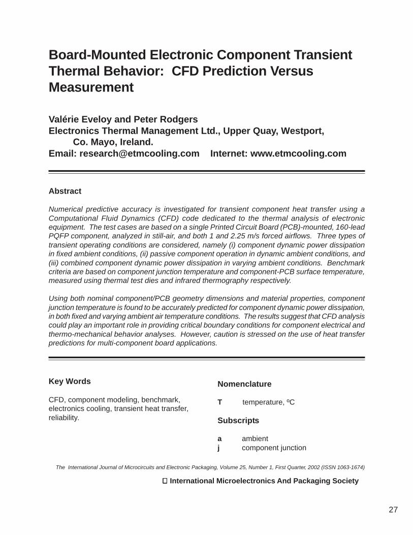
The detailed component model is representedin Figure 3, with the free and forced convectionnumerical models shown in Figure 4.Computational domain dimensions and griddetails are given in Table 5 for both models.
For the free convection model, thecomputational domain was confined to the fluiddomain in the vicinity of the PCB to permit thecomputational grid to be effectively used tofocus on the resolution of the component-PCBthermofluids. Free-air boundary conditionswere applied at the computational domainboundaries, positioned at a sufficient distancefrom the PCB assembly so that no significantunintentional elliptical effects were introduced.

International Microelectronics And Packaging Society
34
Table 4. Nominal material thermal property values for component and PCB constituent elements
Element Thermal
conductivity (W/m.K)
Density (kg/m3)
Specific heat capacity (J/kg.K)
Encapsulant 0.63 1820 882 Die 117.5 - 0.42 (T-100) 2330 712 Die attach 1.9 - - Leadframe 301.5 8900 385 Heat slug 398.0 8940 385 Leadframe insulation 0.2 - - PCB substrate kip = 0.81, ktp = 0.29 1920 1300 PCB copper tracking 398 8933 383
Note: T = temperature in °C. kip and ktp are in-plane and through-plane thermal
conductivities values respectively [31].
These artificial boundary conditions werepermissible as the enclosure roof did notadversely impact on the buoyant thermalplume emanating from the PCB assembly, andas there was negligible thermal stratificationin the vicinity of the PCB assembly. Thesefree-air boundaries fixed the relative pressure tozero with any incoming air entering at theprescribed ambient temperature of 20°C. Theirlocation was approximately 62 mm from thePCB component- and non-component sides,100 mm from both PCB vertical edges, flushwith the bottom edge of the PCB, and 84 mmabove the PCB top edge.
For the forced convection models, a uniformfree-stream velocity inlet boundary conditionwas applied 57.5 mm upstream of the PCBleading edge, and an outlet vent waspositioned 100 mm downstream of the PCBtrailing edge. The domain was extended tothe wind tunnel test section walls in both the
span-wise and transverse directions. The testsection surfaces were modeled using the codedefault friction setting for smooth surfaces. Asdiscrepancies existed between theprogrammed and measured test section free-stream air temperature cycles, resulting fromthe thermal inertia of the heater, theexperimentally recorded time-temperatureprofiles were modeled using a numericalheater located at the test section inlet, Figure4(b).
Based on infrared measurements of PCBsurface temperature, which revealed negligiblethermal interaction between the PCB and itsmechanical support, this fixture was modeledas non-conducting.
For steady-state free convection heat transfer,the board Grashof number, calculated from thethermographic measurements, was on order106. The calculated board Reynolds number

International Microelectronics And Packaging Society
35
Heat slug
Die
Lead FrameExternal leads
Figure 3. 160-lead PQFP component numerical model
Table 5. Computational domain size and spatial grid discretization detail for the numerical
models, Figure 4.
Free convection model
Forced convection model
x y z x y z Domain size (mm) 193 200 125 235.5 128.0 125.0 Computational grid 124 93 114 132 79 114
International Microelectronics And Packaging Society
36
Y
XZ
PCB connector and mechanical support
Component
Computational domain
PCB
Tracks
(a) Free convection
Note: Gravity vector acts in (-y) direction.Free-air boundary conditions are prescribedat the computational domain boundaries.
Figure 4. Component-PCB numerical models
PCB connector and mechanical support
Test section wall
Y
XZ
TracksComponent
PCB
Inlet
Outlet
NumericalAir heater
Note: Gravity vector acts in (-y) direction.
(b) Forced convection

International Microelectronics And Packaging Society
37
for steady-state heat transfer at 2.25 m/s wason order 104. Consequently, the fluid domainwas solved as laminar for all test cases, withvariable fluid property treatment applied. Forthe transient test cases, both heat transfer andfluid flow were solved as unsteady.
Radiative heat transfer was modeled from thecomponent top and bottom surfaces, PCB FR-4 substrate and copper tracking surfaces.
For both the free and forced convectionmodels, a non-uniform spatial grid was appliedhaving highest density both within thecomponent body to resolve conductive heatspread, and in the near-wall regions, to resolvethe high velocity and temperature gradientswithin the hydrodynamic and temperatureboundary layers respectively, and thus theirnear-wall effects on both surface friction andheat transfer. Extensive sensitivity checkswere performed to obtain grid-independentsolutions. The spatial grid discretization detailsare given in Table 5 for both the free and forcedconvection models.For the transient analyses, a non-uniformtemporal grid was applied having highestdensity in the time intervals where high ratesof temperature change were experimentallyrecorded on the test assembly. The solutionsobtained were verified to be temporal gridindependent. This grid was constructed usingtime steps ranging from 3 ms to 5 s.
Solution convergence was defined when theresidual error sum for each variable wasreduced to the termination error level, whichwas set to the code default settings.
Computation was performed using a DELLPrecision 420 workstation with dual 1 GHzPentium III processor and 1024 MB RAM,operating on Windows 2000 Professional.Computational time varied from on order 4 hoursfor the steady-state free convection case, to 24hours for the transient test cases.
4. Results and Discussion
Before analyzing the transient test cases,predictive accuracy is assessed for steady-state heat transfer, whereby the variable ofthermal capacitance is eliminated.
Steady-state heat transfer
Component junction temperature predictionaccuracy is presented both as an absolutetemperature error (ºC), and percentage valuein Table 6. In both free convection and 1 m/sairflow, prediction accuracy is within -2.3ºC or4% of measurement, but decreases to -3.8ºCor 9% at 2.25 m/s. When account is made ofexperimental error, such accuracy wouldtherefore be sufficient for the temperaturepredictions to be used in steady-stateperformance and reliability analyses [25].
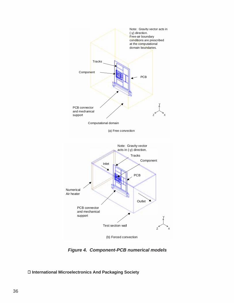
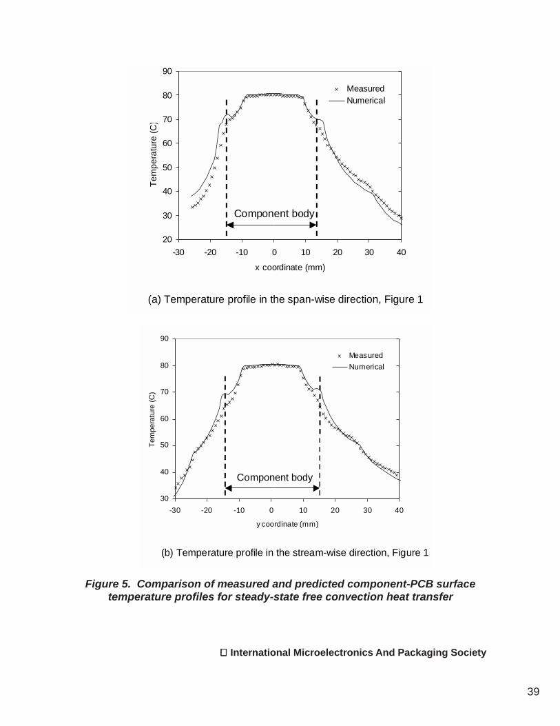
PCB heat spread is also correctly captured bythe model, as shown in Figure 5 for freeconvection, and Figure 6 for 2.25 m/s airflow.In both cases, both the magnitude and shapeof the measured and predicted component-PCB surface temperature profiles are in goodagreement in both the span-wise and stream-wise directions. The discrepancies betweenpredictions and measurements over thecomponent leads are primarily attributed toexperimental error, resulting from the spatialtemperature resolution of the infraredmeasurement system, which would result intemperature averaging over the package leadsand adjacent component top and PCBsurfaces. This factor may also explain thediscrepancy between the measured andpredicted PCB temperatures in the vicinity ofthe component in the span-wise direction infree convection, Figure 5(a), on the profile left-hand side. For this case, large temperaturegradients exist in this region of the board asthe copper tracks only extend by 5 mm fromthe component body, Figure 1. The magnitude

International Microelectronics And Packaging Society
38
Table 6. Comparison of measured and predicted component steady-state junction temperatures
Convecting
environment Measured
(ºC) Prediction
discrepancy (ºC)
Free 83.6 -2.3 (3.6%) Forced, 1 m/s 70.3 -2.1 (4.2%)
Forced, 2.25 m/s 61.8 -3.8 (9.1%)
Note: Measurement accuracy, ±0.4ºC. Percentage prediction error in parenthesis ( ) is calculated based on the measured component junction temperature rise above ambient air temperature. Component power dissipation = 3W. Ambient air temperature = 20ºC.
of the underprediction of component surfacetemperature at 2.25 m/s, Figure 6, is in linewith that for junction temperature in Table 6.This discrepancy is attributed to a slightoverprediction of PCB heat spread, as thepredicted board surface temperature is slightlyhigher than the corresponding measurement,Figure 6. This suggests that the componentjunction temperature prediction error could beattributable to the modeling of the PCB coppertracking. However, computational constraintsprohibit the explicit modeling of its geometricdetail.
Based on these analyses, any significantdecay in component junction predictiveaccuracy for the component dynamic powerdissipation test cases in fixed ambientconditions, Table 1, would be associated withthe modeling of the component-PCB assemblythermal capacitance.
Transient heat transfer
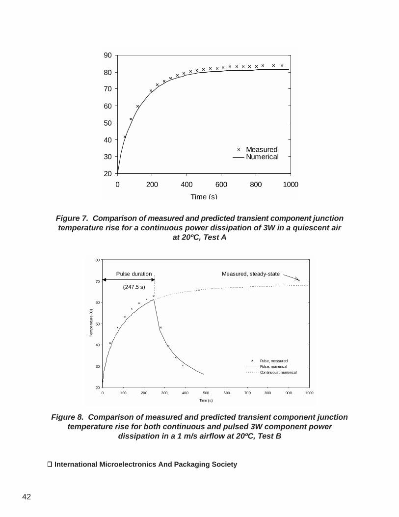
Component dynamic power dissipation in fixedambient conditions, Table 1. The measuredand predicted component transient thermalresponses are compared in Figures 7 and 8 infree convection and 1 m/s airflow respectively.For both convecting environments, predictedcomponent junction temperatures are on orderwithin -2ºC of measurement, indicating that thecomponent-PCB junction-to-ambient thermalimpedance is correctly modeled. It cantherefore be concluded that potentialuncertainties in material thermo-physicalproperties do not impact on predictive accuracyin this instance.
Passive component operation in dynamicambient air temperature conditions, Table 2.The measured and predicted componenttransient thermal responses are compared in
International Microelectronics And Packaging Society
39
Figure 5. Comparison of measured and predicted component-PCB surfacetemperature profiles for steady-state free convection heat transfer
20
30
40
50
60
70
80
90
-30 -20 -10 0 10 20 30 40
x coordinate (mm)
Tem
pera
ture
(C)
MeasuredNumerical
Component body
(a) Temperature profile in the span-wise direction, Figure 1
30
40
50
60
70
80
90
-30 -20 -10 0 10 20 30 40
y coordinate (mm)
Tem
pera
ture
(C)
MeasuredNumerical
Component body
(b) Temperature profile in the stream-wise direction, Figure 1
International Microelectronics And Packaging Society
40
Figure 6. Comparison of measured and predicted component-PCB surfacetemperature profiles for steady-state heat transfer in a 2.25 m/s airflow
20
25
30
35
40
45
50
55
60
65
-30 -20 -10 0 10 20 30
y coordinate (mm)
Tem
pera
ture
( C
)
MeasuredNumerical
Component body
(a) Temperature profile in the span-wise direction, Figure 1
20
25
30
35
40
45
50
55
60
65
-30 -20 -10 0 10 20 30
x coordinate (mm)
Tem
pera
ture
( C
)
MeasurementNumerical
Component body
(b) Temperature profile in the stream-wise direction, Figure 1

International Microelectronics And Packaging Society
41
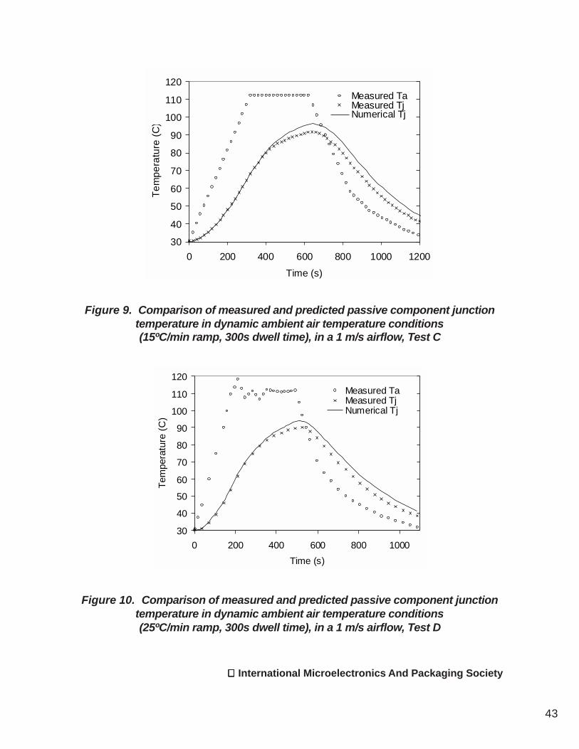
Figures 9 and 10 for 1 m/s airflow, and Figures11 and 12 for 2.25 m/s.
1 m/s air temperature cycles, Tests C and D.During the heating phase of the test assemblyup to approximately 400 s, measured andpredicted component junction temperaturesare in excellent agreement, indicating that thesystem thermal impedance is correctlymodeled. However, measurements andpredictions diverge beyond this point till theend of the imposed dwell, where thediscrepancy stabilizes at a maximum value of4.6ºC and 3.9ºC for tests C and D respectively.Despite this error, the shape of the predictedtransient response during the cooling phaseis in excellent agreement with measurement,as found during the heating phase up to 400s. This trend confirms that the system thermalcapacitance is correctly modeled, with thediscrepancy observed during the dwell periodbeing therefore related to the prediction of thesteady-state thermal resistance. Such adiscrepancy was not found for the componentpowered-on cases, Tests A and B, and isprimarily attributed to experimental error.Though air density variation was numericallyaccounted for, Lohan and Davies [27]measured a 6% increase in airflow velocitywithin the test section for the temperaturerange under analysis. This occurred as thewind tunnel motor operated at a fixed speed,with airflow velocity consequently increasingdue to lower pressure drop. This velocityvariation, which could not be modeled, wouldtherefore result in the slight overprediction ofthe component-PCB thermal resistance duringthe dwell period.
2.25 m/s air temperature cycles, Tests E andF. The same trends are observed at 2.25 m/sin Figures 11 and 12 as for the 1 m/s analyses.However, minor discrepancies can be detectedbetween measurements and predictionsduring the heating phase of the test assembly,
which were not observed at 1 m/s. Thesediscrepancies could be attributable to the loweraccuracy obtained for steady-state heattransfer at 2.25 m/s, Table 6, which impactson the prediction of the test assembly thermaltime constant, hence heating rate.
Combined component dynamic powerdissipation in varying ambient air temperatureconditions, Table 3. Measured and predictedcomponent junction temperatures arecompared in Figures 13 and 14 for 1 m/s and2.25 free-stream air velocities respectively.Overall, the shape of the predicted componenttransient thermal response is in goodagreement with measurement, both during thepowered-on heating phase, and cooling phasebeyond the imposed dwell period. Goodaccuracy is also obtained between the end ofthe power dissipation pulse and the end of thedwell period, during which a complexredistribution of the heat transfer paths occurs.Overall, prediction discrepancies reflect thoseobserved for the active and passivecomponent operation test cases previouslyanalyzed, that is:
(i) The junction-to-ambient thermalimpedance is underestimated duringcomponent dynamic operation, as for Test B.
(ii) The junction-to-ambient thermalimpedance is overestimated from the end ofthe imposed dwell period onwards, as for TestsC – F, which was primarily attributed toexperimental error.
The results of these analyses combined showthat based on both nominal component/PCBgeometry dimensions and material thermo-physical properties, single component-PCBtransient heat transfer can be predicted withgood accuracy, in both free and forcedconvection. In this instance therefore,confidence could be gained in applying CFD
International Microelectronics And Packaging Society
42
Figure 7. Comparison of measured and predicted transient component junctiontemperature rise for a continuous power dissipation of 3W in a quiescent air
at 20ºC, Test A
Figure 8. Comparison of measured and predicted transient component junctiontemperature rise for both continuous and pulsed 3W component power
dissipation in a 1 m/s airflow at 20ºC, Test B
20
30
40
50
60
70
80
90
0 200 400 600 800 1000Time (s)
MeasuredNumerical
20
30
40
50
60
70
80
0 100 200 300 400 500 600 700 800 900 1000
Time (s)
Tem
pera
ture
(C
)
Pulse, measuredPulse, numericalContinuous, numerical
Pulse duration
(247.5 s)
Measured, steady-state
International Microelectronics And Packaging Society
43
30
40
50
60
70
80
90
100
110
120
0 200 400 600 800 1000 1200Time (s)
Tem
pera
ture
(C)
Measured TaMeasured TjNumerical Tj
Figure 9. Comparison of measured and predicted passive component junctiontemperature in dynamic ambient air temperature conditions(15ºC/min ramp, 300s dwell time), in a 1 m/s airflow, Test C
Figure 10. Comparison of measured and predicted passive component junctiontemperature in dynamic ambient air temperature conditions(25ºC/min ramp, 300s dwell time), in a 1 m/s airflow, Test D
30
40
50
60
70
80
90
100
110
120
0 200 400 600 800 1000Time (s)
Tem
pera
ture
(C)
Measured TaMeasured TjNumerical Tj

International Microelectronics And Packaging Society
44
Figure 11. Comparison of measured and predicted passive component junctiontemperature in dynamic ambient air temperature conditions(5ºC/min ramp, 60s dwell time), in a 2.25 m/s airflow, Test E
Figure 12. Comparison of measured and predicted passive component junctiontemperature in dynamic ambient air temperature conditions(15ºC/min ramp, 60s dwell time), in a 2.25 m/s airflow, Test F
30
40
50
60
70
80
90
100
110
120
0 500 1000 1500 2000Time (s)
Tem
pera
ture
(C)
Measured TaMeasured TjNumerical Tj
30
40
50
60
70
80
90
100
110
120
0 200 400 600 800Time (s)
Tem
pera
ture
(C)
Measured TaMeasured TjNumerical Tj

International Microelectronics And Packaging Society
45
Figure 13. Comparison of measured and predicted transient component junctiontemperature rise for a pulsed 3W component power dissipation in dynamic
ambient air temperature conditions (15ºC/min ramp, 60s dwell time), in a 1 m/s airflow, Test G
Figure 14. Comparison of measured and predicted transient component junctiontemperature rise for a pulsed 3W component power dissipation in dynamic ambient
air temperature conditions (15ºC/min ramp, 60s dwell time), in a 2.25 m/s airflow, Test H
30
40
50
60
70
80
90
100
110
120
0 200 400 600 800Time(s)
Tem
pera
ture
(C)
Measured TaMeasured TjNumerical TjPulse
duration
(180s)
Pulse duration
(180s)
30
40
50
60
70
80
90
100
110
120
0 200 400 600 800Time (s)
Tem
pera
ture
(C)
Measured TaMeasured TjNumerical Tj
Pulse duration
(180s)

International Microelectronics And Packaging Society
46
analysis to generate temperature boundaryconditions for use in product electrical andthermo-mechanical performance analyses.This approach would permit the generation ofmore realistic temperature boundaryconditions, as opposed to those obtained usingprescribed convective heat transfer boundaryconditions derived from semi-empiricalanalysis. The passive component operationcases in varying ambient conditions indicatethat CFD analysis could also be used tooptimize assembly processes, where the aimis to minimize thermal gradients, hencestresses. Conversely, CFD analysis couldserve to determine HALT (Highly AcceleratedLife Testing) parameters. Such variables maybe difficult, if not impossible to measureexperimentally.
The results also suggest that the componentmodeling methodology employed would besufficiently robust to be used for the derivationof dynamic component Compact ThermalModels (CTMs) [33,34]. This study cantherefore be seen as a contribution to this area.The assessment of detailed modelingmethodologies for transient component heattransfer has recently been investigated bySchweitzer and Pape [35] using dual cold plateboundary conditions. In contrast to theapproach employed in the present study,however, the lead frame geometry wasexplicitly modeled.
Nevertheless, as predictive accuracy forsteady-state component heat transfer hasbeen found to significantly decay from single-to multi-component board applications[18,19,22,24], this issue is anticipated to havea comparable impact for the analysis oftransient operating conditions. In suchinstances therefore, caution should bestressed on applying CFD-generatedtemperature predictions to performance andreliability analyses.
5. Conclusions
Conjugate transient heat transfer from a singleboard-mounted electronic component wasnumerically modeled using a CFD codededicated to the thermal analysis of electronicequipment.
Using both nominal component/PCB geometrydimensions and material thermo-physicalproperties, component junction temperatureprediction accuracy was found to be accuratelypredicted for component dynamic powerdissipation, in both fixed and varying ambientair temperature conditions.
The results suggest that CFD analysis couldplay an important role in providing criticalboundary conditions for component electricalperformance and thermo-mechanical behavioranalyses.
However, based on previous studies, cautionis stressed on the use of CFD-generatedtemperature predictions for multi-componentboard applications.
Acknowledgments
The authors gratefully acknowledge Flomerics,UK, for the use of Flotherm and their technicalsupport. The test vehicles were built andthermally characterized at the StokesResearch Institute, University of Limerick,Ireland, and the experimental measurementswere supplied by Dr. John Lohan, Galway-Mayo Institute of Technology, Ireland,
The contents of this manuscript werepresented at the Eighth Intersociety Conferenceon Thermal and Thermomechanical Phenomenain Electronic Systems (ITHERM 2002), SanDiego, CA, USA, May 29-June 1, 2002. Thissymposium was co-sponsored by IMAPS.
International Microelectronics And Packaging Society
47
References
[1] K. Azar, Editorial, Electronics Cooling,Vol. 5, No. 3, pp. 1, 1999.
[2] R. K. Kirschman, “Low TemperatureElectronics”, IEEE Circuits and Devices, Vol.6, Part 2, pp.12-24, 1990.
[3] P. Lall, M. Pecht, and E. Harkim,“Influence of Temperature on Microelectronicsand System Reliability,” CRC Press, New York,1997.
[4] J. Parry, J. Rantala, and C. J. M.Lasance, ”Enhanced Electronic SystemReliability – Challenges for TemperaturePrediction,” Proceedings of the SeventhInternational Workshop on ThermalInvestigations of ICs and Systems(THERMINIC), pp. 29-35, 2001.
[5] Z. Kathir, and S. Lefebvre, “ThermalAnalysis of Power Cycling Effects on HighPowerIGBT Modules by the Boundary ElementMethod,” Proceedings of the SeventeenthIEEE Semiconductor Thermal Measurementand Management Symposium (SEMI-THERMXVII), pp. 27-34, 2001.
[6] P. M. Igic, P. A. Mawby, M. S. Towers,and S. Batcup, “Dynamic Electro-ThermalPhysically Based Compact Models of the PowerDevices for Device and Circuit Simulations,”Proceedings of the Seventeenth IEEESemiconductor Thermal Measurement andManagement Symposium (SEMI-THERM XVII),pp. 35-42, 2001.
[7] S. Wen, and G. Q. Lu, “Finite ElementModeling of Thermal and ThermomechanicalBehavior for Three-dimensional Packaging ofPower Electronics Modules,” Proceedings ofthe Seventh Intersociety Conference onThermal and Thermomechanical Phenomenain Electronic Systems (ITHERM’2000), Vol. II,pp. 303-309, 2000.
[8] F. Sarvar, and D. C. Whalley, “IGBTPackage Design for High Power AircraftElectronic Systems,” Proceedings of theSeventh Intersociety Conference on Thermaland Thermomechanical Phenomena inElectronic Systems (ITHERM’2000), Vol. II,pp.391-397, 2000.
[9] M. Pecht, “Why Traditional ReliabilityPrediction Models Do Not Work – Is there anAlternative,” Electronics Cooling, Vol. 2, No.1, pp. 10-12, 1996.
[10] D. Das, “Use of Thermal AnalysisInformation in Avionics EquipmentDevelopment,” Electronics Cooling, Vol. 5, No.3, pp. 28-34, 1999.
[11] M. Osterman, “We Still Have A HeadacheWith Arrhenius,” Electronics Cooling, Vol. 7, No.1, pp. 53-54, 2001.
[12] M. Warner, J. Parry, C. Bailey, C.Marooney, H. Reeves, and K. Pericleous, “Flo/Stress: An Integrated Stress Solver for the CFDTool Flotherm,” Proceedings of IPACK’01: ThePacific Rim/ASME International ElectronicPackaging technical Conference andExhibition, Paper No. IPACK2001-15740,2001.
[13] J. Wakil, and P. S. Ho., “NonuniformTemperature and Strain Fields in a PoweredPackage,” IEEE Transactions on Componentsand Packaging Technologies, Vol. 23, No 3,2000.
[14] B. A. Zahn, and R. P. Stout, “Evaluationof Isothermal and Isoflux Natural ConvectionCoefficient Correlations For Utilization inElectronic Package Level Thermal Analysis,”Proceedings of the Thirteenth IEEESemiconductor Thermal Measurement andManagement Symposium (SEMI-THERM XIII),pp. 24-31, 1997.

International Microelectronics And Packaging Society
48
[18] P. Rodgers, “An ExperimentalAssessment of Numerical Predictive Accuracyfor Electronic Component Heat Transfer,”Ph.D. Thesis, University of Limerick, Limerick,Ireland, 2000.
[19] P. Rodgers, V. Eveloy, and M. Davies,“An Experimental Assessment of NumericalPredictive Accuracy for Electronic ComponentHeat Transfer in Forced Convection: Parts Iand II,” Transactions of the ASME, Journal ofElectronic Packaging, Vol. 125, No. 1, March2003.
[20] W. H. Down, “Achieving Consistency inIR Reflow,” Electronic Packaging and Production,pp. 110-113, 1991.
[21] P. Rodgers, V. Eveloy, J. Lohan, C.M.Fager, P. Tilikka, and J. Rantala, “ExperimentalValidation of Numerical Heat Transfer Predictionsfor Single- and Multi-component Printed CircuitBoards in Natural Convection Environments,”Proceedings of the Fifteenth IEEE Semiconduc-tor Thermal Measurement and ManagementSymposium (SEMI-THERM XV), pp. 55-64,1999.
[22] V. Eveloy, J. Lohan, and P. Rodgers,“A Benchmark Study of Computational FluidDynamics Predictive Accuracy for Component-Printed Circuit Board Heat Transfer,” IEEETransactions on Components and PackagingTechnology (CPT), Vol. 23, Number 3, pp. 568-577, 2000.
[23] V. Eveloy, P. Rodgers, P., and J. Lohan,“Numerical Heat Transfer Predictive Accuracyfor an In-Line Array of Board-Mounted PQFPComponents in Free Convection,”Proceedings of the Third InternationalConference on Thermal and MechanicalSimulation in (Micro)Electronics (EuroSimE),Paris, France, April 14-16, 2002.
[24] Eveloy, V., and Rodgers, P., “NumericalPrediction of Electronic Component HeatTransfer: An Industry Perspective,” to bepublished in the Proceedings of the NineteenthIEEE Semiconductor Thermal Measurementand Management Symposium (SEMI-THERMXIX), 2003.
[25] C. J. M. Lasance, “The need for achange in Thermal Design Philosophy,”Electronics Cooling, Vol. 1, No. 2, pp. 24-26,1995.
[26] M. Davies, J. Lohan, J. Punch, and T.Moore, “The Thermal Characteristics of aBoard-Mounted 160 Lead Plastic Quad FlatPack,” Proceedings of EUROTHERM Seminar29, Editors, C. J. Hoogendoorn, R. A. W. M.Henkes, and C. J. M. Lasance, KluwerAcademic Publishers, 1993.
[27] J. Lohan, and M. Davies, “TransientThermal Behaviour of a Board-Mounted 160-Lead Plastic Quad Flat Pack,” Proceedings ofthe Fourth Intersociety Conference on ThermalPhenomena in Electronic Systems (ITHERM’94),1994.
[15] H. Pape, “Treatment of Convection andRadiation without CFD in Thermal ResistanceCalculations,” Proceedings of the SeventhInternational Workshop on ThermalInvestigations of ICs and Systems(THERMINIC), pp. 43-49, 2001.
[16] V. Eveloy, “Interim PhD report,”Department of Mechanical & IndustrialEngineering, Galway-Mayo Institute ofTechnology, Galway, Ireland, 2002.
[17] A. M. Anderson, and R. J. Moffat, “ANew Type of Heat Transfer Correlation for AirCooling of Regular Arrays of ElectronicComponents,” ASME HTD Thermal Modellingand Design of Electronic Systems andDevices, Vol. 153, pp. 27-39, 1990.

International Microelectronics And Packaging Society
49
[28] SEMI G32-94, “Guide Line forUnencapsulated Thermal Test Chip”, SEMIInternational Standards, Packaging Volume.
[29] SEMI standard G38-87, “Test Method -Still- and Forced Air Junction-to-Ambient ThermalResistance Measurements of Integrated CircuitPackages”, SEMI International Standards,Packaging Volume, pp. 173-178.
[30] Flotherm, Version 3.1 Reference andUser Manuals, Flomerics Limited, Bridge Road,Hampton Court, Surrey, KT8 9HH, UnitedKingdom, 2000.
[31] J. E. Graebner, and K. Azar, “ThermalConductivity Measurements in Printed WiringBoards,” Transactions of the ASME, Journalof Heat Transfer, Vol. 119, No. 3, pp. 401-405,1997.
[32] H. Rosten, J. Parry, J. Addison, R.Viswanath, M. Davies, and E. Fitzgerald,“Development, Validation and Application of aThermal Model of a PQFP”, Proceedings of the45th ECTC, pp. 1140, 1995.
[33] F. Christiaens, E. Beyne, B.Vandevelde, J. Roggen, R. Mertens, J. VanPuymbroeck, M. Heerman, and J. Berghmans,“Compact Transient Thermal Models for thePolymer Stud Grid Array (PSGA) Package,”Proceedings of the 58th Seminar on ThermalManagement of Electronics Systems(EUROTHERM) September 24-26, Nantes,France, pp. 202-209, 1997.
[34] G. Noebauer, “Creating CompactModels Using Standard SpreadsheetSoftware,” Proceedings of the SeventeenthIEEE Semiconductor Thermal Measurementand Management Symposium (SEMI-THERM), pp. 126-133, 2001.
[35] D. Schweitzer, and H. Pape, “ThermalImpedance of Packages in Dual Cold PlateEnvironments,” Proceedings of the SeventhInternational Workshop on ThermalInvestigations of ICs and Systems(THERMINIC), pp. 245-249, 2001.

International Microelectronics And Packaging Society
50
Valérie Eveloy received the M.Sc. degreein physical engineering from the NationalInstitute of Applied Science (INSA), France in1994. She has been involved in electronicsthermal management for eight years, and iscurrently a consulting engineer with ElectronicsThermal Management, Ireland, a research andconsulting firm specialized in electronicscooling. Part of her work at ETM will besubmitted for the award of a Ph.D. degree inthermal-fluid sciences in 2003. Ms. Eveloy waspreviously a Research Engineer at NokiaResearch Center, Finland, where her activitiesfocused on the thermal management oftelecommunication products. She hasauthored or co-authored over fifteen refereedconference and journal papers.
Dr. Peter Rodgers is director of ElectronicsThermal Management, Ltd .He holds the Ph.D.degree in mechanical engineering from theUniversity of Limerick, Ireland and has beeninvolved in electronics thermal managementfor twelve years. Dr. Rodgers was formerlywith the Nokia Research Center, Finland,where he consulted on electronics thermalmanagement within the corporation, and leada research programme on benchmarking thepredictive accuracy of CFD codes dedicatedto the thermal analysis of electronic equipment.For publications associated with this work, hewas awarded the 1999 Harvey Rosten Awardfor Excellence. Dr. Rodgers is a member of theEuroSIME, SEMI-THERM and THERMINICconference program committees and hasauthored or co-authored approximately thirtyrefereed conference and journal publications. Hehas been an invited lecturer, session chair, andpanelist to discussions on simulation issues inelectronics thermal management at internationalconferences.
Author’s Biographies


![COMPUTATIONAL FLUID DYNAMICS (CFD) …...revisions to AWS D10.10 [1] or other heat treating codes. Temperature predictions were obtained from conjugate heat transfer (CHT) analysis](https://static.fdocuments.in/doc/165x107/5e8c49ba3465c14bd51a82ca/computational-fluid-dynamics-cfd-revisions-to-aws-d1010-1-or-other-heat.jpg)