BOARD LEVEL RELIABILITY COMPARISON OF LEAD … · BOARD LEVEL RELIABILITY COMPARISON OF LEAD FREE...
13
BOARD LEVEL RELIABILITY COMPARISON OF LEAD FREE ALLOYS Robert Darveaux, Corey Reichman, Sabira Enayet, Wen-Sung Hsu, and Win Thandar Swe Amkor Technology, Inc. Chandler, AZ, USA [email protected] ABSTRACT Board level reliability testing was used to compare six lead free alloys to tin-lead eutectic using a 98 ball Wafer Level Chip Scale Package (WLCSP). The component had a 0.5mm Ball Grid Array (BGA) pitch, and Al/NiV/Cu pad metallization. Thermal cycling (4 conditions), cyclic bend (2 conditions), cyclic drop (3 conditions), and solder joint array tensile testing (3 conditions) were utilized to compare the alloys. The effects of reflow conditions and aging conditions were quantified. In drop testing, first failures were in the range of 4 to 1000 drops. Most samples failed by a mixture of bulk solder and interface failure. Drop test life improved with increased Ag content. The effect of mild aging after surface mount was positive for most alloys. The effect of multiple reflows was mixed. In solder joint array tensile testing, the Ductile-to-brittle transition strain rate (DTBTSR) was in the range of 0.3/sec to 80/sec. DTBTSR improved with decreasing Ag content and with room temperature aging, but it degraded with multiple reflows. In cyclic bend testing, first failures were in the range of 1000 to 5000 cycles. SAC405 and 63Sn37Pb had the best performance. A 3mm bend deflection had 2x to 3x longer life compared to a 4mm bend deflection. In temperature cycling, first failures were in the range of 100 to 6000 cycles. Fatigue life increased with Ag content for the SAC alloys. Sn0.7Cu showed good performance under all conditions. 63Sn37Pb showed good performance under 35C<=>110C condition. Sn3.5Ag had poor performance under all conditions due to voiding and some interface failures. Key words: Board Level Reliability, Lead Free Solder, Thermal Cycle Test, Cyclic Bend Test, Cyclic Drop Test INTRODUCTION Lead free solders have been shipping in production for several years. However, there is no clear convergence on the alloy of choice for the electronics industry. Instead, there seems to be continuous work on new alloy derivatives in an effort to improve performance. A tin rich system is by far the most commonly used. Typical additions are silver and copper. After that, minor additions of nickel, bismuth, antimony, etc, have been employed. Ball alloy selection for a given BGA package depends on factors such as pad metallization, reflow process conditions, test handling environment, and field application environment. Solder joint failures can occur due to several possible causes -impact loading during test socketing - impact loading during shipping - PCB bending during product assembly - PCB bending during key pad actuation - PCB bending during drop impact - thermal expansion mismatch during temperature cycling - thermal expansion mismatch during power cycling - creep rupture due to PCB bending in product assembly No single lead free alloy has proven to be superior for all combinations of pad metallization, process conditions, and field use environment. Hence, the industry uses several alloys today, and will continue to do so in the future. The purpose of the present study is to evaluate the board level reliability of several lead free alloys under a range of accelerated test conditions using a common test vehicle. A 98 ball Wafer Level Chip Scale Package (WLCSP) was utilized for the study and it was tested under thermal cycling (4 conditions), cyclic bend (2 conditions), cyclic drop (3 conditions), and solder joint array tensile testing (3 conditions). The effects of surface mount reflow conditions and aging after surface mount were quantified. The alloys evaluated in this work are listed in Table 1. All of these alloys are used in production today. Tin-lead eutectic was also evaluated as the control sample. Table 1. Solder Alloys Alloy Name Code 63Sn37Pb Eutectic SnPb 6337 Sn4.0Ag0.5Cu SAC405 4005 Sn3.0Ag0.5Cu SAC305 3005 Sn1.2Ag0.5Cu0.05Ni SAC125Ni 1255 Sn1.0Ag0.5Cu SAC105 1005 Sn3.5Ag Eutectic SnAg 6535 Sn0.7Cu Eutectic SnCu 9307 TEST VEHICLE AND SAMPLE PREPARATION The test vehicle used in the present study was a 98 ball WLCSP with a 0.5mm Ball Grid Array (BGA) pitch, and Al/NiV/Cu pad metallization. The component dimensions are shown in Figure (1a), and a schematic of the cross sectional dimensions after mounting to the test board is shown in Figure (1b). As originally published in the SMTA International Conference Proceedings.
Transcript of BOARD LEVEL RELIABILITY COMPARISON OF LEAD … · BOARD LEVEL RELIABILITY COMPARISON OF LEAD FREE...
BOARD LEVEL RELIABILITY COMPARISON OF LEAD FREE ALLOYS
Robert Darveaux, Corey Reichman, Sabira Enayet, Wen-Sung Hsu, and Win Thandar Swe Amkor Technology, Inc.
Chandler, AZ, USA [email protected]
ABSTRACT Board level reliability testing was used to compare six lead free alloys to tin-lead eutectic using a 98 ball Wafer Level Chip Scale Package (WLCSP). The component had a 0.5mm Ball Grid Array (BGA) pitch, and Al/NiV/Cu pad metallization. Thermal cycling (4 conditions), cyclic bend (2 conditions), cyclic drop (3 conditions), and solder joint array tensile testing (3 conditions) were utilized to compare the alloys. The effects of reflow conditions and aging conditions were quantified. In drop testing, first failures were in the range of 4 to 1000 drops. Most samples failed by a mixture of bulk solder and interface failure. Drop test life improved with increased Ag content. The effect of mild aging after surface mount was positive for most alloys. The effect of multiple reflows was mixed. In solder joint array tensile testing, the Ductile-to-brittle transition strain rate (DTBTSR) was in the range of 0.3/sec to 80/sec. DTBTSR improved with decreasing Ag content and with room temperature aging, but it degraded with multiple reflows. In cyclic bend testing, first failures were in the range of 1000 to 5000 cycles. SAC405 and 63Sn37Pb had the best performance. A 3mm bend deflection had 2x to 3x longer life compared to a 4mm bend deflection. In temperature cycling, first failures were in the range of 100 to 6000 cycles. Fatigue life increased with Ag content for the SAC alloys. Sn0.7Cu showed good performance under all conditions. 63Sn37Pb showed good performance under 35C<=>110C condition. Sn3.5Ag had poor performance under all conditions due to voiding and some interface failures. Key words: Board Level Reliability, Lead Free Solder, Thermal Cycle Test, Cyclic Bend Test, Cyclic Drop Test INTRODUCTION Lead free solders have been shipping in production for several years. However, there is no clear convergence on the alloy of choice for the electronics industry. Instead, there seems to be continuous work on new alloy derivatives in an effort to improve performance. A tin rich system is by far the most commonly used. Typical additions are silver and copper. After that, minor additions of nickel, bismuth, antimony, etc, have been employed.
Ball alloy selection for a given BGA package depends on factors such as pad metallization, reflow process conditions, test handling environment, and field application environment. Solder joint failures can occur due to several possible causes -impact loading during test socketing - impact loading during shipping - PCB bending during product assembly - PCB bending during key pad actuation - PCB bending during drop impact - thermal expansion mismatch during temperature cycling - thermal expansion mismatch during power cycling - creep rupture due to PCB bending in product assembly No single lead free alloy has proven to be superior for all combinations of pad metallization, process conditions, and field use environment. Hence, the industry uses several alloys today, and will continue to do so in the future. The purpose of the present study is to evaluate the board level reliability of several lead free alloys under a range of accelerated test conditions using a common test vehicle. A 98 ball Wafer Level Chip Scale Package (WLCSP) was utilized for the study and it was tested under thermal cycling (4 conditions), cyclic bend (2 conditions), cyclic drop (3 conditions), and solder joint array tensile testing (3 conditions). The effects of surface mount reflow conditions and aging after surface mount were quantified. The alloys evaluated in this work are listed in Table 1. All of these alloys are used in production today. Tin-lead eutectic was also evaluated as the control sample. Table 1. Solder Alloys
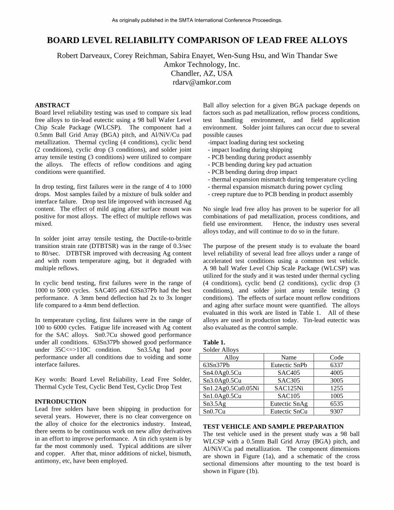
Alloy Name Code 63Sn37Pb Eutectic SnPb 6337 Sn4.0Ag0.5Cu SAC405 4005 Sn3.0Ag0.5Cu SAC305 3005 Sn1.2Ag0.5Cu0.05Ni SAC125Ni 1255 Sn1.0Ag0.5Cu SAC105 1005 Sn3.5Ag Eutectic SnAg 6535 Sn0.7Cu Eutectic SnCu 9307 TEST VEHICLE AND SAMPLE PREPARATION The test vehicle used in the present study was a 98 ball WLCSP with a 0.5mm Ball Grid Array (BGA) pitch, and Al/NiV/Cu pad metallization. The component dimensions are shown in Figure (1a), and a schematic of the cross sectional dimensions after mounting to the test board is shown in Figure (1b).
As originally published in the SMTA International Conference Proceedings.

The test boards had 4 metal layers and a polyimide based laminate material set. The composite elastic modulus measured by Dynamic Mechanical Analysis (DMA) in 3-point bending mode was 16.3 GPa at -55C and 13.5 GPa at 125C. The composite thermal expansivity was 18.1ppm/C in the X-direction and 14.2ppm/C in the Y-direction over the temperature range from -55C to 125C. The surface mount reflow profile is shown in Figure 2. Either 1 pass or 4 pass reflow conditions were utilized. After SMT, the samples were aged at either 22C or 125C before testing. Samples were surface mounted by using a flux only process (not solder paste) in order to minimize voiding effects and to measure the baseline performance of each alloy without the influence of mixing it with a solder paste alloy. However, it is recognized that in most applications, the BGA alloy does mix with the SMT solder paste alloy to form the final solder joint alloy. For example, the BGA alloy might be SAC105 and the solder paste alloy might be SAC305, so the final alloy might be approximately SAC125. This effect was not studied in the present work. CYCLIC DROP TEST Drop testing was conducted per JEDEC Standard JESD22-B111. The input shock pulse was 1500G’s, half sine, with 0.5msec duration. The event detector was set to trigger at 1000 Ohms. A representative test board with samples mounted on it is shown in Figure 3. Exceptions to the JEDEC standard were that the test board was 4 metal layers (instead of 1-4-1 construction) and 5 units were mounted per board (instead of 15 or 4). All 5 samples were included in the data analysis. Three conditions were tested for each alloy type - 1 pass reflow + 24hrs / 22C aging - 4 pass reflow + 24hrs / 22C aging - 1 pass reflow + 6months / 22C aging A Weibull plot for the case of 1 pass reflow + 24hrs / 22C aging is shown for all alloy types in Figure 4. The performance is quite good, with nearly all samples passing over 200 drops before failure. The failure mode summary for this data set after 2650 drops is shown in Figure 5. Solder failure was the most prevalent failure mode. The higher Ag content alloys had more non-failed samples at the end of the test. A Weibull plot for the case of 4 pass reflow + 24hrs / 22C aging is shown for all alloy types in Figure 6. The performance has degraded compared to Figure 4, especially for the 63Sn37Pb alloy. It should be noted that same reflow profile was used for alloy alloys. Hence, the 63Sn37Pb alloy spent much longer time above liquidus (183C) compared to the lead free alloys. A more realistic comparison for future work would be to optimize the profile for 63Sn37Pb (maybe 215C peak instead of 245C).
6.70
7.20
0.506.70
7.20
0.50
a) WLCSP dimensions.
b) Cross sectional dimensions
Figure 1. Sample configuration.
UCSP98 Surface Mount Reflow Profile
0
50
100
150
200
250
0 100 200 300 400 500 600
Time (seconds)
Tem
p (
C)
Figure 2. Surface mount reflow profile.
0.25
0.28
0.062
1.06
0.60
0.200.25
0.28
0.062
1.06
0.60
0.20
As originally published in the SMTA International Conference Proceedings.

The failure mode summary for this data set is shown in Figure 7. Solder failure was the most prevalent failure mode. For the higher Ag content alloys, trace failures increased, and there were more non-failed samples at the end of the test. A Weibull plot for the case of 1 pass reflow + 6months / 22C aging is shown for all alloy types in Figure 8. The performance is quite good, with nearly all samples passing over 200 drops before failure. The failure mode summary for this data set is shown in Figure 9. Solder failure was the most prevalent for low Ag content alloys, and trace failure was more common for high Ag content alloys. There were many more non-failed samples at the end of the test compared to the other two data sets A summary of the most prevalent failure modes for all the “solder” failures is shown in Table 2. Pictures of representative fracture surfaces for solder failures are shown in Table 3. Nearly all solder joint failures resulted from crack propagation near the WLCSP interface. The crack path was either through the bulk solder or through the interface intermetallics. In many cases, there was a mixed fracture path. SAC105, SAC125Ni and Sn3.5Ag showed a higher incidence of bulk solder failure mode. SAC305, SAC405, Sn0.7Cu, and 63Sn37Pb showed more mixed failure mode. Only 63Sn37Pb alloy with 4X reflow showed clean interface failure mode, and the resulting poor performance was clearly shown in Figure 6. Some of the joints had small voids at the WLCSP pad interface. This was especially evident for Sn3.5Ag samples. The void size appeared to grow with 4X reflows. A summary of the drop test results and alloy ranking when considering the first failure of the population are given in Table 4 and Figure 10. SAC405 was the best overall performer. Since the failure mode was mixed between interface and bulk solder failure, and the drop test life was relatively long (100s to 1000s of drops) it is likely that the higher creep resistance of SAC405 resulted in improved performance. Simulation results have shown that higher creep resistance results in a lower strain energy density per drop “cycle,” and a longer predicted fatigue life [1]. This should be true as long as the applied strain rate has not exceeded the ductile-to-brittle transition strain rate. The effect of 6 months room temperature aging was mixed. It extended drops to first failure for SAC105, SAC125Ni, 63Sn37Pb, and Sn3.5Ag. The effect of multiple reflows was mixed. It improved performance for SAC105 and SAC125Ni, but degraded performance for 63Sn37Pb and Sn3.5Ag A summary of the drop test results and alloy ranking when considering the mean failure of the population are given in Table 5 and Figure 11. These results are mostly consistent with the results comparison based on first failure. SAC405 was the best overall performing alloy.
The effect of 6 months room temperature aging was positive for almost every alloy. Theoretically, this would be expected if the effect of aging were to soften the solder to a point where the failure mode changed from interface failure to bulk solder failure. Such a change generally improves drop test life. In the present study, the failure modes were either bulk solder or mixed in the un-aged condition. Furthermore, the failure mode did not change significantly with aging based on Table 2. Hence it is not obvious why the life improved with room temperature aging for most alloys.
Figure 3. Drop test board with assembled units Figure 4. Drop test results for 1 pass reflow + 24hrs / 22C aging.
Drop Test Results UCSP98 245C x 1 Pass
Cycles -to- Failure
Cum
ulat
ive
% F
aile
d
10.000 10000.000100.000 1000.0001.000
5.000
10.000
50.000
90.000
99.00099 Drop Data\6337 X 1Weibull-2PRRX SRM MED FMF=18/S=1
Data PointsProbability Line
Drop Data\6535 X 1Weibull-2PRRX SRM MED FMF=14/S=6
Data PointsProbability Line
Drop Data\SAC105 X 1Weibull-2PRRX SRM MED FMF=17/S=1
Data PointsProbability Line
Drop Data\SAC125 X 1Weibull-2PRRX SRM MED FMF=19/S=1
Data PointsProbability Line
Drop Data\SAC305 x 1Weibull-2PRRX SRM MED FMF=16/S=4
Data PointsProbability Line
Drop Data\SAC405 x 1Weibull-2PRRX SRM MED FMF=13/S=7
Data PointsProbability Line
Drops to Failure10 100 1,000 10,000
1
5
10
50
90
Cu
mu
lati
ve
Fai
lure
s (%
)
63Sn37Pb
SAC105
SAC305
SAC405
Sn3.5Ag
SAC125Ni
Drop Test Results UCSP98 245C x 1 Pass
Cycles -to- Failure
Cum
ulat
ive
% F
aile
d
99.0
10.000 10000.000100.000 1000.0001.000
5.000
10.000
50.000
90.000
0099 Drop Data\6337 X 1Weibull-2PRRX SRM MED FMF=18/S=1
63Sn37Pb90 Data Points
Probability Line
Drop Data\6535 X 1Weibull-2PRRX SRM MED FMF=14/S=6
Data PointsProbability Line
Drop Data\SAC105 X 1Weibull-2PRRX SRM MED FMF=17/S=1
Data PointsProbability Line
Drop Data\SAC125 X 1Weibull-2PRRX SRM MED FMF=19/S=1
Data PointsProbability Line
Drop Data\SAC305 x 1Weibull-2PRRX SRM MED FMF=16/S=4
Data PointsProbability Line
Drop Data\SAC405 x 1Weibull-2PRRX SRM MED FMF=13/S=7
Data PointsProbability Line
Drops to Failure10 100 1,000 10,000
1
5
10
50
Cu
mu
lati
ve
Fai
lure
s (%
)
Sn3.5Ag
SAC105
SAC125Ni
SAC305
SAC405
As originally published in the SMTA International Conference Proceedings.

Figure 5. Drop test failure mode summary after 2650 drops for 1 pass reflow + 24hrs / 22C aging. Figure 6. Drop test results for 4 pass reflow + 24hrs / 22C aging. Figure 7. Drop test failure mode summary after 2650 drops for 4 pass reflow + 24hrs / 22C aging.
Figure 8. Drop test results for 1 pass reflow + 6 months / 22C aging. Figure 9. Drop test failure mode summary after 2650 drops for 1 pass reflow + 6 months / 22C aging. Table 2. Drop test failure mode summary for samples with failures occurring in the solder joint 1 pass reflow
+ 24hrs / 22C 4 pass reflow + 24hrs / 22C
1 pass reflow + 6Mo / 22C
63Sn37Pb
Mixed Interface Bulk / Mixed
SAC405 Mixed Interface / Mixed
Interface / Mixed
SAC305 Mixed Mixed Interface / Mixed
SAC125Ni
Bulk Bulk Bulk / Mixed
SAC105
Bulk / Mixed Bulk / Mixed Bulk / Mixed
Sn3.5Ag
Bulk Bulk Bulk
Sn0.7Cu
Interface / Mixed
Mixed
1X 245C + 24hrs/22C
0%
20%
40%
60%
80%
100%
1005 1255 6337 3005 6535 4005Solder Alloy
Fa
ilure
Mo
de
No Failure
Trace Failure
Solder Failure
4X 245C + 24hrs/22C
0%
20%
40%
60%
80%
100%
9307 1005 1255 6337 3005 6535 4005
Solder Alloy
Fa
ilure
Mo
de
No Failure
Trace Failure
Solder Failure
1X 245C + 6Mo/22C
0%
20%
40%
60%
80%
100%
9307 1005 1255 6337 3005 6535 4005Solder Alloy
Fai
lure
Mo
de
No Failure
Trace Failure
Solder Failure
Drop Test 4x Reflow
Cycles -to- Failure
Cum
ulat
ive
% F
aile
d
1.000 10000.00010.000 100.000 1000.0001.000
5.000
10.000
50.000
90.000
99.000Drop test\1005 4xWeibull-2PRRX SRM MED FMF=18/S=2
Data PointsProbability Line
Drop test\1255 4xWeibull-2PRRX SRM MED FMF=18/S=2
Data PointsProbability Line
Drop test\3005 4xWeibull-2PRRX SRM MED FMF=14/S=6
Data PointsProbability Line
Drop test\4005 4xWeibull-2PRRX SRM MED FMF=5/S=12
Data PointsProbability Line
Drop test\6337 4xWeibull-2PRRX SRM MED FMF=18/S=0
Data PointsProbability Line
Drop test\6535 4xWeibull-2PRRX SRM MED FMF=20/S=0
Data PointsProbability Line
Drop test\9307 4xWeibull-2PRRX SRM MED FMF=16/S=2
Data PointsProbability Line
Drops to Failure10 100 1,000 10,000
1
5
10
50
90
99
Cu
mu
lati
ve
Fai
lure
s (%
)
63Sn37Pb
SAC105
SAC305
SAC405
Sn3.5Ag
SAC125Ni
1
Sn0.7Cu
Drop Test Results for 6mos 22C Single Pass Reflow
Failed Cycle
Unr
elia
bilit
y, F
(t)
10.000 10000.000100.000 1000.00001.00
5.000
10.000
50.000
90.000
99.000Folio1\1005RTAWeibull-2PRRX SRM MED FMF=8/S=12
Data PointsProbability Line
Folio1\1255RTAWeibull-2PRRX SRM MED FMF=13/S=7
Data PointsProbability Line
Folio1\3005RTAWeibull-2PRRX SRM MED FMF=5/S=15
Data PointsProbability Line
Folio1\4005RTAWeibull-2PRRX SRM MED FMF=4/S=8
Data PointsProbability Line
Folio1\6337RTAWeibull-2PRRX SRM MED FMF=11/S=9
Data PointsProbability Line
Folio1\6535RTAWeibull-2PRRX SRM MED FMF=7/S=12
Data PointsProbability Line
Folio1\9307RTAWeibull-2PRRX SRM MED FMF=13/S=6
Data PointsProbability Line
Drops to Failure10 100 1,000 10,000
1
5
10
50
90
99
Cu
mu
lati
ve
Fa
ilure
s (%
)
63Sn37Pb
SAC105
SAC305
SAC405
Sn3.5Ag
SAC125Ni
Sn0.7Cu
As originally published in the SMTA International Conference Proceedings.

Table 3 Fracture surfaces for drop tests
1 Pass Reflow + 24hrs / 22C 4 Pass Reflow + 24hrs / 22C 1 Pass Reflow + 6Mo / 22C 63Sn37Pb
Sn4.0Ag0.5Cu
Sn3.0Ag0.5Cu
Sn1.2Ag0.5Cu0.05Ni
Sn1.0Ag0.5Cu
Sn3.5Ag
Sn0.7Cu
As originally published in the SMTA International Conference Proceedings.

Table 4 Alloy ranking for 1st Failure in drop tests
7263415Ranking 1X245C + 6Mo/22C
=-=--++Effect of Multiple Reflows
--+-+++Effect of 22C Aging
1537426Ranking 4X245C + 24hr/22C
123465Ranking 1X245C + 24hr/22C
4005653530056337125510059307
7263415Ranking 1X245C + 6Mo/22C
=-=--++Effect of Multiple Reflows
--+-+++Effect of 22C Aging
1537426Ranking 4X245C + 24hr/22C
123465Ranking 1X245C + 24hr/22C
4005653530056337125510059307
1
10
100
1000
9307 1005 1255 6337 3005 6535 4005
Alloy
Fir
st F
ailu
re (D
rop
s)
1X 245C + 6Mo/22C
1X 245C + 24hrs/22C
4X 245C + 24hrs/22C
9307 = Sn0.7Cu1005 = Sn1.0Ag0.5Cu1255 = Sn1.2Ag0.5Cu0.05Ni6337 = 63Sn37Pb3005 = Sn3.0Ag0.5Cu6535 = Sn3.5Ag4005 = Sn4.0Ag0.5Cu
1
10
100
1000
9307 1005 1255 6337 3005 6535 4005
Alloy
Fir
st F
ailu
re (D
rop
s)
1X 245C + 6Mo/22C
1X 245C + 24hrs/22C
4X 245C + 24hrs/22C
9307 = Sn0.7Cu1005 = Sn1.0Ag0.5Cu1255 = Sn1.2Ag0.5Cu0.05Ni6337 = 63Sn37Pb3005 = Sn3.0Ag0.5Cu6535 = Sn3.5Ag4005 = Sn4.0Ag0.5Cu
Figure 10. Alloy comparison for 1st Failure in drop tests. Table 5 Alloy ranking for Mean Failure in drop tests
2216457Ranking 1X245C + 6Mo/22C
+-+-++Effect of Multiple Reflows
=+++++Effect of 22C Aging
1627435Ranking 4X245C + 24hr/22C
124563Ranking 1X245C + 24hr/22C
4005653530056337125510059307
2216457Ranking 1X245C + 6Mo/22C
+-+-++Effect of Multiple Reflows
=+++++Effect of 22C Aging
1627435Ranking 4X245C + 24hr/22C
124563Ranking 1X245C + 24hr/22C
4005653530056337125510059307
100
1000
10000
9307 1005 1255 6337 3005 6535 4005
Alloy
Me
an
Lif
e (
Dro
ps
)
1X 245C + 6Mo/22C
1X 245C + 24hrs/22C
4X 245C + 24hrs/22C
Figure 11. Alloy comparison for Mean Failure in drop tests.
As originally published in the SMTA International Conference Proceedings.

SOLDER JOINT ARRAY TENSILE TEST Tensile testing of solder joint arrays was performed as described in Refs [2-4]. The samples were formed by soldering a WLCSP to a PCB with solder mask defined pads. The WLCSP sandwiches were glued into fixtures and tested at strain rates between 0.0095/sec and 81/sec at 22C. The strain rate is defined as the crosshead rate divided by joint height. The fraction of joints with a brittle interface failure mode was recorded for each test. The ductile-to-brittle transition strain rate (DTBTSR) was defined at the point where 50% of the joints had a brittle failure mode. The solder joint array tensile test results for 1 pass reflow + 24hrs / 22C aging are shown in Figure 12. DTBTSR ranged from 2.9/sec to greater than 81/sec. SAC105 and Sn3.5Ag had the best performance. Figure 12. Tensile test results for 1 pass reflow + 24hrs / 22C aging. Figure 13. Tensile test results for 4 pass reflow + 24hrs / 22C aging.
Tensile test results for 4 pass reflow + 24hrs / 22C aging are shown in Figure 13. DTBTSR ranges from 0.3/sec to 24/sec. Sn3.5Ag had the best performance. Tensile test results for 1 pass reflow + 6 Mo / 22C aging are shown in Figure 14. DTBTSR ranges from 3.1/sec to greater than 81/sec. 63Sn37Pb had the best performance. A summary of DTBTSR for all tests is shown in Figure 15. It is seen that 6 Mo / 22C aging improves performance significantly for 63Sn37Pb and Sn0.7Cu. Four pass reflow had negative impact on performance for all alloys.
0%
10%20%
30%
40%50%
60%
70%
80%90%
100%
1.E-03 1.E-02 1.E-01 1.E+00 1.E+01 1.E+02
Strain Rate (1/sec)
Bri
ttle
Fai
lure
s (%
)
63Sn37Pb
SAC405
SAC305
SAC125Ni
Sn3.5Ag
Sn0.7Cu
0%
10%
20%
30%
40%
50%
60%
70%
80%
90%
100%
1.E-03 1.E-02 1.E-01 1.E+00 1.E+01 1.E+02
Strain Rate (1/sec)
Bri
ttle
Fai
lure
s (%
)
63Sn37Pb
SAC405SAC305
SAC125Ni
SAC105Sn3.5Ag
Sn0.7Cu
Figure 14. Tensile test results for 1 pass reflow + 6 months / 22C aging.
1.E-01
1.E+00
1.E+01
1.E+02
63S
n37
Pb
SA
C40
5
SA
C30
5
SA
C12
5Ni
SA
C10
5
Sn
3.5A
g
Sn
0.7C
u
DT
BT
SR
(1/
sec)
1 Pass Reflow + 6Mo / 22C
1 Pass Reflow + 24hrs / 22C
4 Pass Reflow + 24hrs / 22C
0%
10%
20%
30%
40%
50%
60%
70%
80%
90%
100%
1.E-03 1.E-02 1.E-01 1.E+00 1.E+01 1.E+02
Strain Rate (1/sec)
Bri
ttle
Fai
lure
s (%
)
63Sn37Pb
SAC405
SAC305
SAC125NiSAC105
Sn3.5Ag
Sn0.7Cu
Figure 15. Alloy comparison for ductile-to-brittle transition strain rate (DTBTSR).
As originally published in the SMTA International Conference Proceedings.

CYCLIC BEND TEST Four point bend testing was conducted per JESD22B113 with the exception that the test board was 4 layer construction (instead of 1-4-1). The support span was 110mm and the load span was 75mm. The load anvil deflection was either 3mm or 4mm. The cyclic frequency was 1Hz. Daisy chain samples were continuously monitored. The 3mm deflection tests were monitored with an event detector set to trigger at 1000 Ohms. The 4mm deflection tests were monitored with a data logger, and a 1ohm increase failure criteria was used. A test board with 9 WLCSPs mounted on it is shown in Figure 16. Bend test results for samples with 1 pass reflow + 10 mo / 22C aging with 3mm bend deflection are shown in Figure 17. First failures ranged from 2200 cycles to 5200 cycles. Typical failures occurred through the bulk solder on the component side of the solder joints. Bend test results for samples with 1 pass reflow + 24hrs / 125C aging with 4mm bend deflection are shown in Figure 18. First failures range from 500 to 2500 cycles. Typical failures occurred through the bulk solder on the component side of the solder joints. The alloy ranking and comparison with respect to first failure is shown in Table 6 and Figure 19. 63Sn37Pb and SAC405 had the best performance. SAC305, Sn3.5Ag, and Sn0.7Cu had the worst performance. The alloy ranking and comparison with respect to mean failure is shown in Table 7 and Figure 20. 63Sn37Pb and SAC405 alloys had the best performance. SAC305, Sn3.5Ag, and SAC125Ni had the worst performance. Tests with 3mm load anvil deflection had 2x to 3x longer life than those with 4mm deflection. The effect of post reflow aging was evaluated for only the SAC125Ni alloy (code = 1255) and a 3mm deflection condition. The samples with 24hrs / 125C aging had 20% longer life than those with 10 mo / 22C aging. THERMAL CYCLE TEST Lead free alloys were tested under four thermal cycle conditions, as shown in Figure 21. A populated thermal test board is shown in Figure 22. Daisy chain samples were continuously monitored, and the event detector was set to trigger at 500 Ohms. The results for -55C<=>125C, 2cph test condition are shown in Figure 23. First failure ranged from 131 cycles to 304 cycles. Mean life ranged from 170 cycles to 408 cycles. Sn0.7Cu had the best performance and Sn3.5Ag had the worst performance. The results for 0C<=>100C, 2cph test condition are shown in Figure 24. First failure ranged from 295 cycles to 841 cycles. Mean life ranged from 686 cycles to 1316 cycles. SAC405 had the best performance and Sn3.5Ag and 63Sn37Pb had the worst performance.
The results for 35C<=>110C, 1cph test condition are shown in Figure 25. First failure ranged from 437 cycles to 2403 cycles. Mean life ranged from 1200 cycles to 3500 cycles. 63Sn37Pb had the best performance and Sn3.5Ag had the worst performance.
Figure 16. Bend test board with assembled units Figure 17. Bend test results for 3mm bend deflection with 1 pass reflow + 10 months / 22C aging. Figure 18. Bend test results for 4mm bend deflection with 1 pass reflow + 24hrs / 125C aging.
4MM Cyclic Bend
Cycles -to- Failure
Cum
ula
tive
% F
aile
d
100.000 100000.0001000.000 10000.0001.000
5.000
10.000
50.000
90.000
99.000BEND\SAC105Weibull-2PRRX SRM MED FMF=26/S=0
Data PointsProbability Line
BEND\SAC125Weibull-2PRRX SRM MED FMF=25/S=0
Data PointsProbability Line
BEND\SAC305Weibull-2PRRX SRM MED FMF=17/S=0
Data PointsProbability Line
BEND\SAC405Weibull-2PRRX SRM MED FMF=26/S=0
Data PointsProbability Line
BEND\6337Weibull-2PRRX SRM MED FMF=24/S=0
Data PointsProbability Line
BEND\6535Weibull-2PRRX SRM MED FMF=27/S=0
Data PointsProbability Line
Bend Cycles to Failure
100,0001,000 10,0001
5
10
50
90
99
Cu
mu
lati
ve
Fai
lure
s (%
)
63Sn37Pb
SAC305
SAC405
Sn3.5Ag
SAC125Ni
100
SAC105
4MM Cyclic Bend
Cycles -to- Failure
Cum
ula
tive
% F
aile
d
100.000 100000.0001000.000 10000.00001. 00
5.0 00
10.000
50.000
90.000
99.000BEND\SAC105
F=26/S=0
Weibull-2PRRX SRM MED FM
Data PointsProbability Line
BEND\SAC125Weibull-2PRRX SRM MED FMF=25/S=0
Data PointsProbability Line
BEND\SAC305Weibull-2PRRX SRM MED FMF=17/S=0
Data PointsProbability Line
BEND\SAC405
F=26/S=0
Weibull-2PRRX SRM MED FM
Data PointsProbability Line
BEND\6337
F=24/S=0
Weibull-2PRRX SRM MED FM
Data PointsProbability Line
BEND\6535
F=27/S=0
Weibull-2PRRX SRM MED FM
Data PointsProbability Line
Bend Cycles to Failure
100,0001,000 10,
3mm Cyclic Bend 10 mos @ 22C aging
Cycles -to- Failure
Cum
ulat
ive
% F
aile
d
0001
5
10
50
90
99
Cu
mu
lati
ve
Fai
lure
s (%
)
63Sn37Pb
SAC305
SAC405
Sn3.5Ag
SAC125Ni
100
SAC105
1000.000 100000.00010000.00001. 00
5.000
10.000
50.000
90.000
99.0003mm\6337Weibull-2PRRX SRM MED FMF=26/S=0
Data PointsProbability Line
3mm\6535Weibull-2PRRX SRM MED FMF=18/S=0
Data PointsProbability Line
3mm\9307Weibull-2PRRX SRM MED FMF=26/S=0
Data PointsProbability Line
3mm\SAC125Weibull-2PRRX SRM MED FMF=27/S=0
Data PointsProbability Line
3mm\SAC305Weibull-2PRRX SRM MED FMF=17/S=0
Data PointsProbability Line
3mm\SAC405Weibull-2PRRX SRM MED FMF=27/S=0
Data Points
Bend Cycles to Failure
100,0001,000 10,0001
5
10
50
90
99
Cu
mu
lati
ve
Fai
lure
s (%
)63Sn37Pb
SAC305
SAC405
Sn3.5Ag
SAC125Ni
Sn0.7Cu
3mm Cyclic Bend 10 mos @ 22C aging
Cycles -to- Failure
Cum
ulat
ive
% F
aile
d
1000.000 100000.00010000.00001. 00
5.000
10.000
50.000
90.000
99.0003mm\6337Weibull-2PRRX SRM MED FMF=26/S=0
Data PointsProbability Line
3mm\6535Weibull-2PRRX SRM MED FMF=18/S=0
Data PointsProbability Line
3mm\9307Weibull-2PRRX SRM MED FMF=26/S=0
Data PointsProbability Line
3mm\SAC125Weibull-2PRRX SRM MED FMF=27/S=0
Data PointsProbability Line
3mm\SAC305Weibull-2PRRX SRM MED FMF=17/S=0
Data PointsProbability Line
3mm\SAC405Weibull-2PRRX SRM MED FMF=27/S=0
Data Points
Bend Cycles to Failure
100,0001,000 10,0001
5
10
50
90
9963Sn37Pb
Cu
mu
lati
ve
Fai
lure
s (%
)
Sn3.5Ag
Sn0.7Cu
SAC125Ni
SAC305
SAC405
As originally published in the SMTA International Conference Proceedings.

Table 6 Alloy ranking for 1st Failure in bend tests
245136Ranking 10Mo/22C – 3mm
165342Ranking 24hr/125C – 4mm
4005653530056337125510059307
245136Ranking 10Mo/22C – 3mm
165342Ranking 24hr/125C – 4mm
4005653530056337125510059307
1000
10000
9307 1005 1255 6337 3005 6535 4005
Alloy
Fir
st
Fa
ilure
(C
yc
les
)
1X 245C + 10Mo/22C(3mm Bend)
1X 245C + 24hrs/125C(3mm Bend)
1X 245C + 24hrs/125C(4mm Bend)
Figure 19. Alloy comparison for 1st Failure in bend tests. Table 7 Alloy ranking for Mean Failure in bend tests
163254Ranking 10Mo/22C – 3mm
246153Ranking 24hr/125C – 4mm
4005653530056337125510059307
163254Ranking 10Mo/22C – 3mm
246153Ranking 24hr/125C – 4mm
4005653530056337125510059307
1000
10000
9307 1005 1255 6337 3005 6535 4005
Alloy
Mea
n L
ife
(C
yc
les
)
1X 245C + 10Mo/22C(3mm Bend)
1X 245C + 24hrs/125C(3mm Bend)
1X 245C + 24hrs/125C(4mm Bend)
Figure 20. Alloy comparison for Mean Failure in bend tests.
As originally published in the SMTA International Conference Proceedings.

The results for 35C<=>85C, 1cph test condition are shown in Figure 26. First failure ranged from 1801 cycles to 6302 cycles. Mean life ranged from 6500 cycles to 9800 cycles. Sn0.7Cu and SAC405 had the best performance and Sn3.5Ag had the worst performance.
-60
-40
-200
20
40
60
80100
120
140
0 10 20 30 40 50 60
Time (minutes)
Tem
p (
C)
-55<=>125C, 2cph
0<=>100C, 2cph 35<=>110C, 1cph
35<=>85C, 1cph
Figure 21. Thermal cycle conditions.
Figure 22. Thermal cycle test board with units. Figure 23. Results for -55C<=>125C, 2cph test condition.
Figure 24. Results for 0C<=>100C, 2cph test condition. Figure 25. Results for 35C<=>110C, 1cph test condition. Figure 26. Results for 35C<=>85C, 1cph test condition.
0-100C 2CPH
Cycles -to- Failure
Cum
ulat
ive
% F
aile
d
100.000 10000.0001000.0001.000
5.000
10.000
50.000
90.000
99.000Probability-Weibull
Folio1\6337Weibull-2PRRX SRM MED FMF=30/S=0
Data PointsProbability Line
Folio1\6535Weibull-2PRRX SRM MED FMF=29/S=0
Data PointsProbability Line
Folio1\9307Weibull-2PRRX SRM MED FMF=29/S=1
Data PointsProbability Line
Folio1\SAC125Weibull-2PRRX SRM MED FMF=30/S=0
Data PointsProbability Line
Folio1\SAC305Weibull-2PRRX SRM MED FMF=25/S=4
Data PointsProbability Line
Folio1\SAC405Weibull-2PRRX SRM MED FMF=24/S=6
Data PointsProbability Line
Corey ReichmanAmkor Technology8/5/20094:55:39 PM
Temperature Cycles to Failure
1,000 10,0001
5
10
50
90
99
Cu
mu
lati
ve
Fai
lure
s (%
)
63Sn37Pb
SAC305
SAC405
Sn3.5Ag
SAC125Ni
100
Sn0.7Cu
0-100C 2CPH
Cycles -to- Failure
Cum
ulat
ive
% F
aile
d
100.000 10000.0001000.00001.00
5.000
10.000
50.000
90.000
99.000Probability-Weibull
Folio1\6337Weibull-2PRRX SRM MED FMF=30/S=0
Data PointsProbability Line
Folio1\6535Weibull-2PRRX SRM MED FMF=29/S=0
Data PointsProbability Line
Folio1\9307Weibull-2PRRX SRM MED FMF=29/S=1
Data PointsProbability Line
Folio1\SAC125Weibull-2PRRX SRM MED FMF=30/S=0
Data PointsProbability Line
Folio1\SAC305Weibull-2PRRX SRM MED FMF=25/S=4
Data PointsProbability Line
Folio1\SAC405Weibull-2PRRX SRM MED FMF=24/S=6
Data PointsProbability Line
Corey ReichmanAmkor Technology8/5/20094:55:39 PM
Temperature Cycles to Failure
1,000 10,0001
5
10
50
90
99
Cu
mu
lati
ve
Fai
lure
s (%
)
63Sn37Pb
SAC305
SAC405
Sn3.5Ag
SAC125Ni
100
Sn0.7Cu
35-110C 1 CPH
Cycles -to- Failure
Cum
ulat
ive
% F
aile
d
100.000 10000.0001000.0001.000
5.000
10.000
50.000
90.000
99.000Folio1\6337Weibull-2PRRX SRM MED FMF=19/S=11
Data PointsProbability Line
Folio1\6535Weibull-2PRRX SRM MED FMF=30/S=0
Data PointsProbability Line
Folio1\9307Weibull-2PRRX SRM MED FMF=19/S=11
Data PointsProbability Line
Folio1\SAC125Weibull-2PRRX SRM MED FMF=23/S=7
Data PointsProbability Line
Folio1\SAC305Weibull-2PRRX SRM MED FMF=26/S=4
Data PointsProbability Line
Folio1\SAC405Weibull-2PRRX SRM MED FMF=16/S=14
Data PointsProbability Line
Temperature Cycles to Failure
1,000 10,0001
5
10
50
90
99
Cu
mu
lati
ve
Fa
ilure
s (%
)
63Sn37Pb
SAC305
SAC405
Sn3.5Ag
SAC125Ni
100
Sn0.7Cu
35-85C 1 CPH
Cycles -to- Failure
Cum
ulat
ive
% F
aile
d
1000.000 10000.0001.000
5.000
10.000
50.000
90.000
99.00035-85C\SAC125Weibull-2PRRX SRM MED FMF=27/S=3
Data PointsProbability Line
35-85C\6337Weibull-2PRRX SRM MED FMF=15/S=15
Data PointsProbability Line
35-85C\6535Weibull-2PRRX SRM MED FMF=23/S=7
Data PointsProbability Line
35-85C\9307Weibull-2PRRX SRM MED FMF=9/S=21
Data PointsProbability Line
35-85C\SAC305Weibull-2PRRX SRM MED FMF=13/S=17
Data PointsProbability Line
35-85C\SAC405Weibull-2PRRX SRM MED FMF=9/S=21
Data PointsProbability Line
Temperature Cycles to Failure
10,0001
5
10
50
90
99
Cu
mu
lati
ve
Fai
lure
s (%
)
63Sn37Pb
SAC305
SAC405
Sn3.5Ag
SAC125Ni
1,000
Sn0.7Cu
-55 to 127C 2cyl/hr
CycleS -to- Failure
Cum
ulat
ive
% F
aile
d
100.000 1000.0001.000
5.000
10.000
50.000
90.000
99.000
6337
6535
9307
SAC125
SAC305
SAC405
Temperature Cycles to Failure
1,0001
5
10
50
90
99
Cu
mu
lati
ve
Fa
ilure
s (%
)
63Sn37Pb
SAC305
SAC405
Sn3.5Ag
SAC125Ni
100
Sn0.7Cu
-55 to 127C 2cyl/hr
CycleS -to- Failure
Cum
ulat
ive
% F
aile
d
100.000 1000.0001.000
5.000
10.000
50.000
90.000
99.000
6337
6535
9307
SAC125
SAC305
SAC405
Temperature Cycles to Failure
1,0001
5
10
50
90
99
Cu
mu
lati
ve
Fa
ilure
s (%
)
63Sn37Pb
SAC305
SAC405
Sn3.5Ag
SAC125Ni
100
Sn0.7Cu
As originally published in the SMTA International Conference Proceedings.

Table 8 Alloy ranking for 1st Failure in thermal cycle tests
264341Ranking -55C125C, 2cph
265431Ranking 35C85C, 1cph
265143Ranking 35C110C, 1cph
154632Ranking 0C100C, 2cph
4005653530056337125510059307
264341Ranking -55C125C, 2cph
265431Ranking 35C85C, 1cph
265143Ranking 35C110C, 1cph
154632Ranking 0C100C, 2cph
4005653530056337125510059307
100
1000
10000
9307 1005 1255 6337 3005 6535 4005
Alloy
Fir
st
Fa
ilure
(C
yc
les
)
-55C<=>125C, 2cph
0C<=>100C, 2cph
35C<=>110C, 1cph
35C<=>85C, 1cph
Figure 27. Alloy comparison for 1st Failure in thermal cycle tests. Table 9 Alloy ranking for Mean Failure in thermal cycle tests
263451Ranking -55C125C, 2cph
263451Ranking 35C85C, 1cph
264153Ranking 35C110C, 1cph
162543Ranking 0C100C, 2cph
4005653530056337125510059307
263451Ranking -55C125C, 2cph
263451Ranking 35C85C, 1cph
264153Ranking 35C110C, 1cph
162543Ranking 0C100C, 2cph
4005653530056337125510059307
100
1000
10000
9307 1005 1255 6337 3005 6535 4005
Alloy
Me
an
Lif
e (
Cy
cle
s)
-55C<=>125C, 1cph
0C<=>100C, 2cph
35C<=>110C, 1cph
35C<=>85C, 1cph
Figure 28. Alloy comparison for Mean Failure in thermal cycle tests.
As originally published in the SMTA International Conference Proceedings.

A comparison of thermal cycle results and alloy ranking with respect to first failure is given in Table 8 and Figure 27. A comparison with respect to mean failure is given in Table 9 and Figure 28. Overall, SAC405 and Sn0.7Cu had the best performance, and Sn3.5Ag had the worst performance. In nearly all cases, the failures occurred through the bulk solder, near the component side of the joint. The poor performance of Sn3.5Ag was somewhat surprising. There were a few interface failures, but mostly the failures occurred through the bulk solder. One factor might have been the degree of voiding near the component pad metallization. The Sn3.5Ag samples had the most voiding compared to other alloys. It is possible that there was a process related issue during ball attach of the WLCSP. To confirm this possibility, a new lot of samples was put on test. 63Sn37Pb performance was strongly dependent on the temperature cycle conditions. It was the best performer under 35C<=>110C, 1cph, but the worst performer under 0C<=>100C, 2cph. DISCUSSION The board level reliability performance of several lead free alloys has been compared under a wide range of test conditions. Cycles to first failure spanned three orders of magnitude. Hence, the test conditions ranged from being quite harsh to being relatively mild. Although there was no single alloy that performed the best under all tests, SAC405 was the most consistently high ranking performer. There have been several previous evaluations comparing some of the lead free alloys studied here. Syed [5] evaluated 12mm-144 fleXBGA packages with 0.8mm pitch and electroplated NiAu pad finish using -40C<=>125C, 1cph temperature cycling. The fatigue life ranking in Phase 1 evaluations was SAC405 > 63Sn37Pb > Sn3.5Ag. Under 0C<=>100C, 2cph conditions, the fatigue life ranking was Sn3.5Ag > SAC405 > 63Sn37Pb. In a Phase 2 evaluation under -40C<=>125C, 1cph conditions, the fatigue life ranking was Sn3.5Ag > SAC405 = Sn0.7Cu = 63Sn37Pb. Under -55C<=>125C, 2cph conditions, the fatigue life ranking was SAC405 > Sn0.7Cu > 63Sn37Pb. Finally, under 0C<=>100C, 2cph conditions, the fatigue life ranking was SAC405 > Sn0.7Cu > 63Sn37Pb. Lin et.al [6] tested non-underfilled flip chip assemblies under 0C<=>100C conditions. The fatigue life ranking was Sn0.7Cu > SAC405 = 63Sn37Pb > Sn3.5Ag. Clech [7] compiled thermal cycle fatigue data from a wide range of components and test conditions and showed that SAC alloy out performs SnPb at “lower” stress conditions, but SnPb was the best performer at “higher” stress conditions.
Syed et.al., [8] compared alloy performance under drop, bend, and temperature cycling conditions for Ni/Au and Cu/OSP pad finishes. They found that higher Ag content alloys were more favorable under temperature cycling conditions, but lower Ag content was more favorable under drop conditions. The change in drop performance was also accompanied by a change in failure mode; i.e., SAC305 (with lower performance) showed interface failures, while SAC105 and SAC125Ni (with higher performance) failed in the bulk solder. Considering the results of the present study along with the work cited above, it is clear that comparing the temperature cycling performance of solder joint alloys is not a simple task. There is a complex interaction between the assembly stiffness, expansion mismatch, solder creep behavior, and temperature cycle conditions that determines the amount of damage per cycle [9]. Hence, the relative alloy ranking for one component might not be the same as for another component. Also, the temperature dependence of the creep behavior varies by alloy type [10]. Hence, one alloy might be subjected to the least damage under one temperature cycling condition, but another alloy might be more favorable under different temperature cycling condition. A high thermal cycle ramp rate will likely have a larger impact on alloys with greater strain rate sensitivity (like 63Sn37Pb). With respect to drop test performance, a key factor is the failure mode. If brittle interface failures are observed, then drop performance is always degraded significantly. The propensity for interface failure depends on two primary factors: 1) the characteristic ductile-to-brittle transition strain rate (DTBTSR) of the solder joints, and 2) the applied strain rate imposed on the joints by the test. If the applied strain rate is greater than the DTBTSR, then interface failures occur readily. The applied strain rate is a function of several factors such as component design and material set, motherboard design and material set, boundary conditions due to restraints on the motherboard, and the level of shock impact loading. In the present study, there was not a perfect correlation between factors that affected DTBTSR and those that affected drop performance. For example, 6 months / 22C aging improved drop test performance for nearly all alloys, but it only had a significant improvement on DTBTSR for 63Sn37Pb and Sn0.7Cu. Four pass reflow degraded DTBTSR for all alloys, but it only degraded drop test performance for 63Sn37Pb and Sn3.5Ag. Perhaps one reason there was imperfect correlation between DTBTSR and drop test performance was that nearly all of the drop tests had a mixed failure mode or bulk solder failure mode. There was only clean interface failure on 63Sn37Pb with four pass reflow. It is likely that if a larger component had been used in the evaluation (which results in a higher applied strain rate to the solder joints) there would have been better correlation between DTBTSR and drop test performance. Simulations are currently being conducted to
As originally published in the SMTA International Conference Proceedings.

estimate the strain rates during the drop test and see how these compare to the measured DTBTSR values for each alloy. Another reason there could be discrepancy between drop testing and solder joint array tensile testing is simply due to the test method differences. The tensile test is monotonic loading event. Conversely, a drop test is cyclic loading, with multiple bend cycles per drop, and multiple drops per test. The joints do not fail in a single stroke. Also, it is possible that the solder work hardens during drop testing due to repeated loading cycles with very little dwell time in between. For example, it was shown that indium solder joints had a yield stress that varied depending on the previous loading cycle and the amount time for stress relaxation between loading cycles [11]. In the study by Syed et.al, [8], lower Ag content SAC alloys had better drop performance because the failure mode changed from bulk solder failure to interface failure as Ag content was increased. The testing was conducted on a 10x10mm - 360 ball CSP. In the present study, higher Ag content SAC alloys had better drop performance because in all cases the failure mode was either bulk solder, or mixed. The current test vehicle was a 6.8x7.2mm – 98 ball WLCSP. CONCLUSIONS 1) Board level reliability testing was used to compare six lead free alloys to tin-lead eutectic using a 98 ball Wafer Level Chip Scale Package (WLCSP). The effects of reflow conditions and aging conditions were quantified. 2) In drop testing, first failures were in the range of 4 to 1000 drops. Most samples failed by a mixture of bulk solder and interface failure. Drop test life improved with increased Ag content. The effect of mild aging after surface mount was positive for most alloys. The effect of multiple reflows was mixed. 3) In solder joint array tensile testing, the ductile-to-brittle transition strain rate (DTBTSR) was in the range of 0.3/sec to 80/sec. DTBTSR improved with decreasing Ag content and with room temperature aging, but it degraded with multiple reflows. 4) In cyclic bend testing, first failures were in the range of 1000 to 5000 cycles. SAC405 and 63Sn37Pb had the best performance. A 3mm bend deflection had 2x to 3x longer life compared to a 4mm bend deflection. 5) In temperature cycling, first failures were in the range of 100 to 6000 cycles. Fatigue life increased with Ag content for the SAC alloys. Sn0.7Cu showed good performance under all conditions. 63Sn37Pb showed good performance under 35C<=>110C condition. Sn3.5Ag had poor performance under all conditions due to voiding and some interface failures.
REFERENCES 1] R. Darveaux, et.al., “Effect of Joint Size and Pad Metallization on Solder Mechanical Properties,” Proc. ECTC, 2008. 2] R. Darveaux, C. Reichman, N. Islam, “Interface Failure in Lead Free Solder Joints,” Proc. ECTC, May 2006. 3] R. Darveaux and C. Reichman, “Ductile-to-Brittle Transition Strain Rate,” Proc EPTC, 2006 4] R. Darveaux, C. Reichman, P. Agrawal, and S.W. Cha, “Effect of Mild Aging on Solder Joint Interface Failure,” Proc. Japan IEEE VLSI Packaging Workshop, 2006. 5] A. Syed, “Reliability of Lead-Free Solder Connections for Area-Array Packages,” IPC SMEMA Council APEX 2001, pp. LF2-7. 6] J-K Lin, J-W Jang, S. Hayes, and D. Frear, “Lead-Free Flip Chip Interconnect Reliability for DCA and FC-PBGA Packages,” Proceedings ECTC 2004, pp. 642-649. 7] J-P Clech, “Lead Free and Mixed Assembly Solder Joint Reliability Trends,” IPC SMEMA Council APEX, 2004. 8] A. Syed et.al, “Impact of Package Design and Materials on Reliability for Temperature Cycling, Bend, and Drop Loading Conditions,” Proceedings ECTC 2008, pp.1453-1461. 9] R. Darveaux, “Effect of Assembly Stiffness and Solder Properties on Thermal Cycle Acceleration Factors,” Proc. 11th International Workshop on Thermal Investigations of ICs and Systems (THERMINC), Belgirate, Lake Maggiore, Italy, 9/27 - 9/30 2005. 10] R. Darveaux and C. Reichman, “Mechanical Properties of Lead-Free Solders,” Proc. ECTC, 2007. 11] R. Darveaux and I. Turlik, "Shear Deformation of Indium Solder Joints," IEEE Transactions on Components, Hybrids, and Manufacturing Technology, Vol 13, No 4, December 1990, pp. 929-939.
As originally published in the SMTA International Conference Proceedings.