BOA V2.9 Tutorial - etas.com · PDF fileThe "Open File" dialog box ... used to indicate...
49
BOA V2.9 Tutorial
-
Upload
hoangthuan -
Category
Documents
-
view
219 -
download
0
Transcript of BOA V2.9 Tutorial - etas.com · PDF fileThe "Open File" dialog box ... used to indicate...

BOA V2.9
Tutorial

2
Copyright
The data in this document may not be altered or amended without special notification
from ETAS GmbH. ETAS GmbH undertakes no further obligation in relation to this docu-ment. The software described in it can only be used if the customer is in possession of a
general license agreement or single license. Using and copying is only allowed in concur-rence with the specifications stipulated in the contract.
Under no circumstances may any part of this document be copied, reproduced, transmit-
ted, stored in a retrieval system or translated into another language without the express written permission of ETAS GmbH.
© Copyright 2010-2016 ETAS GmbH, Stuttgart
The names and designations used in this document are trademarks or brands belonging
to the respective owners.
Document AM900002 V2.0 R01 EN – 11.2013

ETAS Contents
BOA V2.9 Tutorial 3
Contents
1 Introduction ............................................................................................................................ 6
1.1 Safety Notice ................................................................................................................... 6 1.2 User Information .............................................................................................................. 6 1.2.1 What you need to know ............................................................................................... 6 1.2.2 How this Tutorial is organized ....................................................................................... 6 1.3 Definitions and Abbreviations ............................................................................................ 7 1.4 Conventions ..................................................................................................................... 7
2 Overview ................................................................................................................................ 8
2.1 BOA ................................................................................................................................ 8 2.2 OCI Basic Blocks .............................................................................................................. 9 2.2.1 Frequently used code ................................................................................................... 9 2.2.2 How OCI Blocks Integrate .......................................................................................... 10 2.2.3 Controllers ................................................................................................................. 10 2.2.4 Queues ..................................................................................................................... 12 2.2.5 Messages .................................................................................................................. 13 2.2.6 Frames ...................................................................................................................... 14 2.2.7 Events ....................................................................................................................... 14 2.2.8 Filters ........................................................................................................................ 17 2.2.9 Timers ....................................................................................................................... 19
3 CSI ....................................................................................................................................... 20
4 Creating an OCI application ................................................................................................... 24
4.1 How to configure a project from scratch .......................................................................... 24 4.2 Errors and warnings ....................................................................................................... 24 4.3 Troubleshooting ............................................................................................................. 25
5 OCI_CAN and CAN-FD ........................................................................................................... 26
5.1 Minimal Implementation ................................................................................................. 26 5.1.1 Configuring the Device ............................................................................................... 26 5.1.2 Sending ..................................................................................................................... 28 5.1.3 Receiving ................................................................................................................... 29 5.2 Working example : HelloCAN_OCI, HelloCANFD ............................................................... 31 5.2.1 Operation .................................................................................................................. 31
6 OCI_FLEXRAY ....................................................................................................................... 32
6.1 Minimal Implementation: ................................................................................................ 32 6.1.1 Configuring the Device ............................................................................................... 32 6.1.2 Sending ..................................................................................................................... 35 6.1.3 Receiving ................................................................................................................... 36 6.2 Working example : HelloFLX_OCI .................................................................................... 38 6.2.1 Operation .................................................................................................................. 38
7 OCI_LIN ............................................................................................................................... 39
7.1 Minimal Implementation ................................................................................................. 39 7.1.1 Configuring the Device ............................................................................................... 39

ETAS Contents
BOA V2.9 Tutorial 4
7.1.2 LIN Slave ................................................................................................................... 42 7.1.3 LIN Monitoring ........................................................................................................... 43 7.2 Working example: HelloLIN_OCI ..................................................................................... 45 7.2.1 Operation .................................................................................................................. 45
8 ETAS Contact Addresses ........................................................................................................ 46
9 Appendix A – BOA Demo ....................................................................................................... 47
9.1 Description .................................................................................................................... 47 9.2 Location ........................................................................................................................ 47 9.3 Use case examples ......................................................................................................... 47 9.3.1 Example of a more complex application that uses BOA OCI .......................................... 47 9.3.2 Testing configurations and settings for BOA compatible hardware ................................. 47 9.3.3 Sending or receiving data to / from a device on the bus ............................................... 47 9.3.4 A framework on which you can develop your own code ................................................ 48 9.4 How to use the user interface ......................................................................................... 48 9.5 How to change configurations and notes on the code ....................................................... 48
ETAS Figures
BOA V2.9 Tutorial 5
Figures Fig. 1: BOA Architecture .......................................................................................................................... 8
Fig. 2: Integration using OCI .................................................................................................................... 9
Fig. 3: OCI Blocks ................................................................................................................................... 10
Fig. 4: State chart for the virtual controller ........................................................................................... 11
Fig. 5: OCI_CANMessage ....................................................................................................................... 16

ETAS Introduction
BOA V2.9 Tutorial 6
1 Introduction
The Basic Open API (BOA) is a programming interface that allows devices to be configured and used to send and receive data on automotive buses (CAN/LIN/FlexRay).
The tutorial illustrates through many examples how to accomplish simple tasks using BOA,
e.g. how to send and receive frames.
1.1 Safety Notice
DANGER!
Sending out CAN, LIN or FlexRay messages influences the behavior of the bus network and the systems connected to it. This may result in unexpected behavior of the vehicle and thus can have potentially dangerous consequences. Only well-trained personnel should be allowed to perform CAN, LIN or FlexRay message sending activities.
1.2 User Information
1.2.1 What you need to know
We highly advise you to read the User’s Guide first since it gives a deeper look into the BOA
architecture and a better understanding of the concepts used in BOA. Despite that, starting with the tutorial right away is possible – the examples included are ready-to-run, and
provide a good starting point for further understanding. On the other hand, developing a complete application that interfaces to the hardware using BOA definitely requires
understanding the concepts described in the User’s Guide.
This tutorial addresses developers of software tools in the fields of automotive control unit development and calibration.
Basic knowledge of the automotive bus used and of automotive bus controllers is required.
However, specialized knowledge of the ETAS hardware devices and their connection to the
PC is not required.
The code snippets provided in this tutorial are not compiler ready. Rather, they are meant as examples to illustrate what the text is talking about and how it could be done. For ready-to-
compile code, please refer to the source code examples provided with this tutorial. These
can be found in your BOA installation folder in: Examples/EBI-IP_Examples.zip
1.2.2 How this Tutorial is organized
The tutorial comprises the following chapters:
Chapter 1, Introduction, on page 6 (this chapter) gives an overview about who should use this tutorial along with some information to help ease understanding and navigating through the rest of the document.
Chapter 2, Overview, on page 8 gives an overview of the different OCI blocks that will be used very frequently throughout the examples. Grasping the concepts behind how the blocks integrate and what is the role of each is very important for writing software that uses the OCI interface.
Chapter 3, CSI, on page 20 introduces the usage of the Connection Service Interface. Using CSI is essential to find the connected hardware.
Chapter 4, Creating an OCI application, on page 24, chapter 5, OCI_CAN, on page 26, chapter 6, OCI_FLEXRAY, on page 32; and chapter 7, OCI_LIN, on page 39, give walkthroughs for a minimal implementation along with working example projects.
ETAS Introduction
BOA V2.9 Tutorial 7
1.3 Definitions and Abbreviations
OCI
Open Controller Interface; Lowest level interface. It exposes abstract, virtual views to physical hardware controllers. The position of these controllers within the hardware network is transparent to the application software. The number of virtual instances per physical controller is not limited.
For every class of hardware controllers (CAN, LIN, or FlexRay), there is a specialized OCI.
CAN
Controller Area Network; CAN is a vehicle bus standard designed to allow microcontrollers and devices to communicate with each other within a vehicle without a host computer.
CAN-FD
The improved CAN data link layer protocol, CAN-FD, provides higher data throughput than CAN.
FlexRay
FlexRay is a scalable and fault tolerant communication system for high-speed and deterministic data exchange. FlexRay’s time-division multiplexing facilitates the design of modular or safety-related distributed systems.
Its high bandwidth of 10 MBaud on two channels helps to cope with the high network load caused by the increasing amount of innovative electronic systems in modern vehicles.
LIN
Local Interconnect Network; The LIN bus is a small and slow network system that is used as a low-cost sub-network of a CAN bus to integrate intelligent sensor devices or actuators in today’s cars.
The LIN specification is enforced by the LIN-consortium and is continuously enhanced to meet current networking needs.
Rx
Receiver/Receive
Tx
Transmitter/Transmit
1.4 Conventions
The following typographical conventions are used in this document:
Choose File Open. Menu commands are shown in boldface.
Click OK. Buttons are shown in boldface.
Press <ENTER>. Keyboard commands are shown in angled
brackets.
The "Open File" dialog box is displayed. Names of program windows, dialog boxes,
fields, etc. are shown in quotation marks.
Select the file setup.exe Text in drop-down lists on the screen, program
code, as well as path- and file names are shown
in the Courier font.
A distribution is always a one-dimensional
table of sample points.
General emphasis and new terms are set in
italics.
ETAS Overview
BOA V2.9 Tutorial 8
2 Overview
This chapter discusses concepts used in OCI. It gives an overview of the different components, their behavior and their usage.
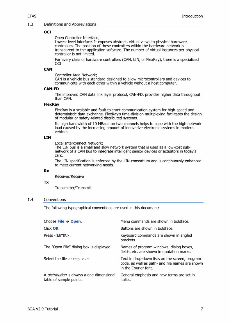
2.1 BOA
The Basic Open API (BOA) is an application-programming interface that allows easy and flexible integration of automotive buses hardware interfaces, whose drivers are BOA
capable, into software applications. BOA is composed of two sub-APIs divided according to functionality. The functional API is the Open Controller Interface (OCI). OCI is a low-level C
interface that allows fast and efficient interaction with the hardware sacrificing the ease of
programming for more efficiency. Along with this API, BOA offers the Connection Service Interface (CSI). CSI provides functionality to dynamically search all connected hardware,
construct the hardware tree view, and present it to the application. It also establishes the initial connection to the hardware. Fig. 1: BOA Architecture illustrates where the OCI and
CSI are used.
Fig. 1: BOA Architecture
Your application can interface with the hardware at the OCI level as shown in Fig. 2: Integration using OCI. You will have to use CSI directly for searching for hardware as shown previously in Fig. 1: BOA Architecture.

ETAS Overview
BOA V2.9 Tutorial 9
Fig. 2: Integration using OCI
2.2 OCI Basic Blocks
This section explains the basic OCI components that are most frequently used. It explains how the components are structured, how they fit together, and how to use them to
implement a sub-task. This section does not explain complete solutions, instead only small
tasks that can be integrated together to form a complete solution.
For a more in-depth look at these topics, please read the User’s Guide that is provided in
Documentation\Users Guide.
For examples of how these basic blocks can be integrated and used together to achieve some meaningful goal, please refer to the individual examples; these can be found in the
Chapters 4, Creating an OCI application, on page 24, 5, OCI_CAN and CAN-FD, on page 26,
6, OCI_FLEXRAY, on page 32, and 7, OCI_LIN, on page 39.
2.2.1 Frequently used code
This tutorial will refer many times to some very frequently used elements and small code snippets without mentioning them at each reuse. These elements and code snippets along
with a brief explanation are shown below.
OCI_ErrorCode
The variable ec is an OCI_ErrorCode used to indicate whether an error occurred during a
specific operation. You can create an OCI_ErrorCode like this:
OCI_ErrorCode ec; // Error code returned by OCI API calls
exitWithMessage
exitWithMessage is a function that simply prints out a message and then exists the
program. This function is a simple way for error handling that will allow spotting where the
error occurred easily without obscuring the real aim of the tutorial—showing how BOA works—by non-relevant code to handle errors. A sample implementation of the function is
provided below.
// Error Handling, Write a message to the console and exit
void exitWithMessage (char* msg)
{
printf ("%s", msg);
ETAS Overview
BOA V2.9 Tutorial 10
// comment the following line if you don’t want the method to halt before
// exiting the program
getchar();
exit (-1);
}
2.2.2 How OCI Blocks Integrate
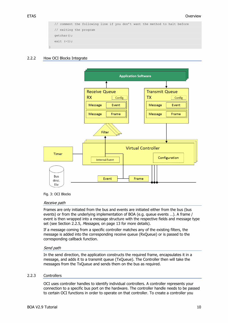
Fig. 3: OCI Blocks
Receive path
Frames are only initiated from the bus and events are initiated either from the bus (bus
events) or from the underlying implementation of BOA (e.g. queue events …). A frame / event is then wrapped into a message structure with the respective fields and message type
set (see Section 2.2.5, Messages, on page 13 for more details).
If a message coming from a specific controller matches any of the existing filters, the message is added into the corresponding receive queue (RxQueue) or is passed to the
corresponding callback function.
Send path
In the send direction, the application constructs the required frame, encapsulates it in a
message, and adds it to a transmit queue (TxQueue). The Controller then will take the messages from the TxQueue and sends them on the bus as required.
2.2.3 Controllers
OCI uses controller handles to identify individual controllers. A controller represents your connection to a specific bus port on the hardware. The controller handle needs to be passed
to certain OCI functions in order to operate on that controller. To create a controller you

ETAS Overview
BOA V2.9 Tutorial 11
need a URI path; this URI path can either be previously known, or can be acquired using
CSI to dynamically find connected hardware.
A controller is always in one of three modes: CREATED, SUSPENDED, or RUNNING. A
controller in the CREATED mode means that a connection has been made to the hardware,
but the hardware is not yet configured. When in SUSPENDED mode, the controller is already
configured and ready for communication, but it will not attempt any communication on the
bus. A controller in the RUNNING mode is a controller that is active and will interact with the
bus when that is needed.
Immediately after its creation, a controller always enters the CREATED mode. By configuring
the controller (using the function OCI_OpenCANController), you switch it from CREATED
to either SUSPENDED or RUNNING using the mode field in your properties structure.
When the controller is in either the SUSPENDED or RUNNING modes, the mode can be
changed from one to the other using the function OCI_SetCANControllerProperties
with the respective input. When the controller is in SUSPENDED or RUNNING modes, it can
go back to CREATED by a call to the function OCI_CloseCANController. Once in the
CREATED mode, it can be opened again with a new configuration set.
Fig. 4: State chart for the virtual controller
If you try to open two controllers that have conflicting configurations on the same hardware
device, the call to OCI_OpenCANController will fail returning an error code.
OCI_ControllerHandle rxctrl; // Controller handle
BOA_Version version = {1,0,0,0};
// The configuration of the CAN controller
OCI_CANConfiguration cancfg =
{
1000000, // Baudrate
50, // Sample Point in percent
OCI_CAN_THREE_SAMPLES_PER_BIT, // Sampling
10, // BTL cycles

ETAS Overview
BOA V2.9 Tutorial 12
1, // Length of the sync segment
OCI_CAN_SINGLE_SYNC_EDGE, // Synchronization edge
OCI_CAN_MEDIA_HIGH_SPEED // Physical CAN media
};
// The properties of the CAN controller
OCI_CANControllerProperties canctrlp =
{
OCI_CONTROLLER_MODE_RUNNING // We start in mode RUNNING. The controller will
// be active on the CAN BUS immediately after
// OCI_OpenCANController
};
// Create CAN controller, on success, it will be in CREATED mode
ec = OCI_CreateCANControllerVersion(uriname[1], &version, &rxctrl);
if (ec != OCI_SUCCESS) exitWithMessage("Error: OCI_CreateCANControllerVersion
failed\n");
// Open and configure the controller (set it to RUNNING mode)
ec = OCI_OpenCANController(rxctrl, &cancfg, &canctrlp);
if (ec != OCI_SUCCESS) exitWithMessage("Error: OCI_OpenCANController failed\n");
OCI gives the application the possibility to know what the hardware devices are capable of
doing. For example, LIN hardware can be capable of only operating as a LIN slave. This can
be done through the function OCI_GetLINControllerCapabilities.
2.2.4 Queues
Queues are used in BOA to hold messages in a First In First Out (FIFO) manner. Queues are
never created alone; they have to be associated with a controller. Queues are also bus and direction specific; i.e. a queue is a CAN receive queue for example. Consequently, Queues
can only hold messages that are of the same bus type and of the same direction as the
queue itself. For example, an OCI_CANTxQueue can hold only CAN messages that are
allowed in the transmit direction; in this case OCI_CANMessage that has the type set to
OCI_CAN_TX_MESSAGE. On the other hand, an OCI_CANRxQueue can hold
OCI_CANMessage with the type set to OCI_CAN_RX_MESSAGE, or
OCI_CAN_TIMER_EVENT, etc. For more information about how messages are structured
and in which direction each message is allowed, please refer to 2.2.5, Messages, on page 13, and the User’s Guide.
Upon the creation of the queue, some configuration information has to be specified. For
receive queues, the configurations should contain information about callbacks assigned to that queue. There is one callback for frames and one for events. When the callbacks are set
to an existing function, messages will be delivered directly to the callback. If a callback is set to null, BOA will queue the corresponding messages, which the application can read when it
is convenient. BOA will drop all messages from a queue unless they match a filter that you
have explicitly assigned to that queue.
Below, code illustrating how to create a queue, attach it to a controller and add a filter to it is shown.
OCI_QueueHandle rxqueue; // Receive Queue handle
OCI_CANRxQueueConfiguration rxcfg =
{
{ RxFrameCallback, //Callback that is triggered, whenever a CAN frame is
ETAS Overview
BOA V2.9 Tutorial 13
// received and passes the filter condition
NULL }, //This value will be passed to the callback whenever it’s called
{ RxEventCallback //Callback that is triggered whenever an event that needs
// to be routed to a callback occurs
NULL }, //This value will be passed to the callback whenever it’s called
OCI_SELF_RECEPTION_OFF // We do not want to receive frames that we
transmit
};
//Create a receive queue. We register callbacks for frame reception and events.
//These callbacks are triggered whenever a frame or event is received and passes
// the filter condition.
// rxctrl is a controller handle in the SUSPENDED or RUNNING state
ec = OCI_CreateCANRxQueue(rxctrl, &rxcfg, &rxqueue);
if (ec != OCI_SUCCESS) exitWithMessage("Error: OCI_CreateCANRxQueue failed\n");
//The receive queue will not receive any data until we have defined some white
//filter. Here we allow any CAN frame to pass the filter, so we receive all frames
//from the CAN-Bus
OCI_CANRxFilter filter = {
0, //frameIDValue - The ID of a received frame ANDed with frameIDMask will
//be compared against this value
0, //frameIDMask - The ID of a received frame will be ANDed with this
//value (will always result in 0 in this example)
0 //This value will be attached to the message if it matches this filter
};
ec = OCI_AddCANRxFilter(rxqueue, filter, 1); //add the filter to the queue
if (ec != OCI_SUCCESS) exitWithMessage("Error: OCI_AddCANFrameFilter failed\n");
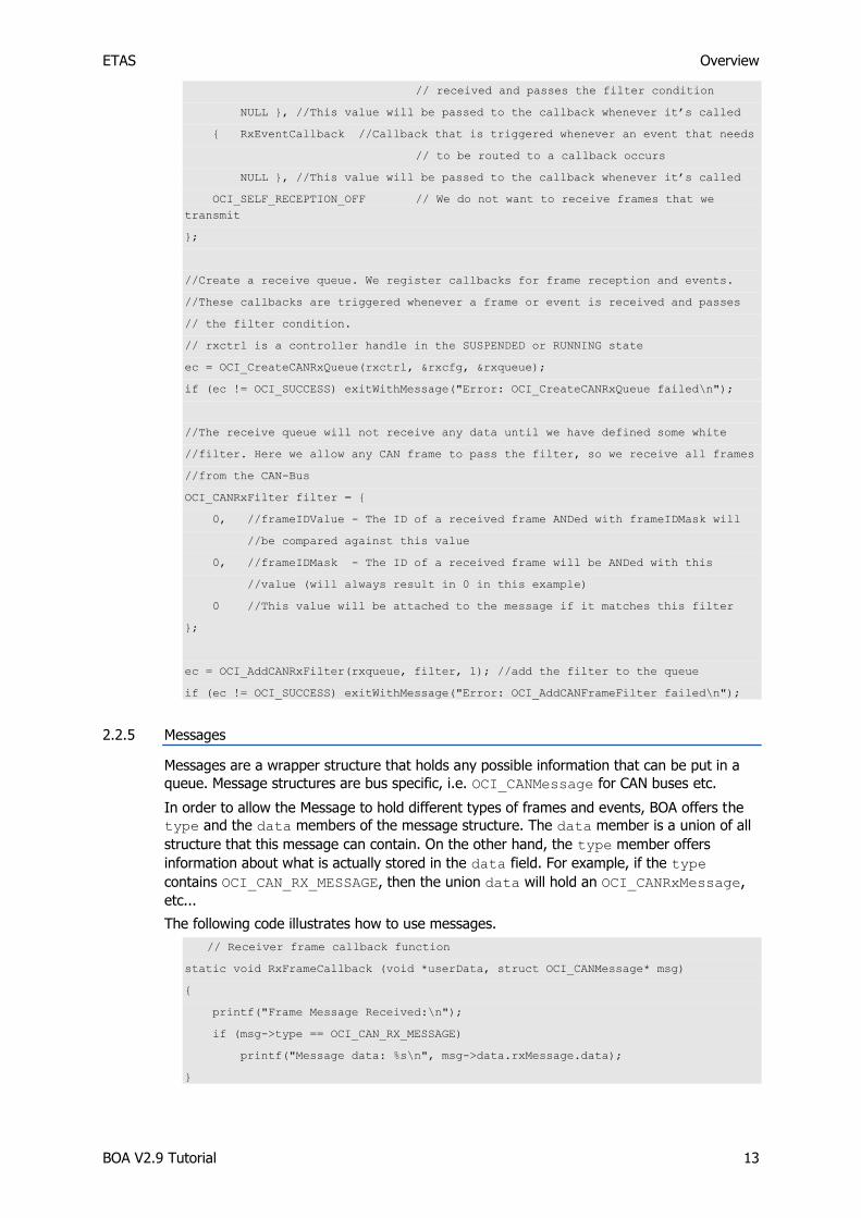
2.2.5 Messages
Messages are a wrapper structure that holds any possible information that can be put in a
queue. Message structures are bus specific, i.e. OCI_CANMessage for CAN buses etc.
In order to allow the Message to hold different types of frames and events, BOA offers the
type and the data members of the message structure. The data member is a union of all
structure that this message can contain. On the other hand, the type member offers
information about what is actually stored in the data field. For example, if the type
contains OCI_CAN_RX_MESSAGE, then the union data will hold an OCI_CANRxMessage,
etc...
The following code illustrates how to use messages.
// Receiver frame callback function
static void RxFrameCallback (void *userData, struct OCI_CANMessage* msg)
{
printf("Frame Message Received:\n");
if (msg->type == OCI_CAN_RX_MESSAGE)
printf("Message data: %s\n", msg->data.rxMessage.data);
}

ETAS Overview
BOA V2.9 Tutorial 14
2.2.6 Frames
Frames are delivered to the application encapsulated in a message structure. Frames
represent something that is sent on the bus; they are exact maps of bus frames. Frames contain bus specific information; thus, there is no standard structure that applies to all BOA
frames. Frames have to match a frame filter before being queued or delivered to a callback function.
You, as an application developer, will also have to construct frames yourself and encapsulate
them in a message in order to be able to send them on the bus.
The code below illustrates how to create, set the type and fill in the frame inside an OCI_CANMessage.
OCI_CANMessage canMessages[1]; // Array of can messages
// OCI_CANTxMessage represents the CAN frame in the send direction, this has to be
// encapsulated in an OCI_CANMessage structure then added to the queue.
OCI_CANTxMessage msg0 =
{
0x0101, // CAN frame ID.
OCI_CAN_MSG_FLAG_EXTENDED, // we use an extended identifier here
0, // Reserved must be
set to 0
7, // DLC: Number of
(valid) data bytes.
"Hello " // payload
};
canMessages[0].type = OCI_CAN_TX_MESSAGE;
canMessages[0].reserved = 0;
memcpy(&canMessages[0].data.txMessage, &msg0, sizeof(msg0));
2.2.7 Events
Events are structures encapsulated in a message that will be sent to the application when
they match a filter. There are two types of events: generic event types that are independent of the bus being used, and bus specific events. The generic event types represent events
specific to BOA, e.g. queue events and timer events. On the other hand, bus specific events are specific to a bus, they represent some change in the bus state or some action that
happened on the bus, e.g. a CAN bus node going into passive mode.
As with frames, events will not be delivered to the application unless they match a filter. There is an event filter type that has to be used for each type of events.
The code below represents a callback function that receives events coming from the bus.
The code shows how the function checks the type of the message received and, according
to that, accesses the correct field and extracts the eventCode.
// Receiver event callback function
static void RxEventCallback (void *userData, struct OCI_CANMessage* msg)
{
printf("Event Message Received:\n");
if (msg->type == OCI_CAN_TIMER_EVENT)
{
if (msg->data.timerEventMessage.eventCode == OCI_TIMER_EVENT_SYNC_LOCK)
printf("Device is Synchronized\n");
else if (msg->data.timerEventMessage.eventCode ==
OCI_TIMER_EVENT_SYNC_LOSS)

ETAS Overview
BOA V2.9 Tutorial 15
printf("Device lost Synchronization\n");
}
else
printf("An unknown Event has occured\n");
}
This code is taken from a callback assigned to an OCI_CANRxQueue. As you can see, the
code checks the type of the message against the expected types according to the applied filter (more on that in Section 2.2.8, Filters, on page 17). After knowing which fields are
valid, the code accesses and uses the data.timerEvent field to retrieve the required
information.
ETAS Overview
BOA V2.9 Tutorial 16
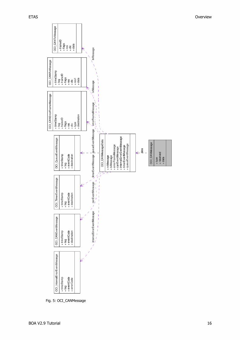
Fig. 5: OCI_CANMessage

ETAS Overview
BOA V2.9 Tutorial 17
The illustration in Fig. 5: OCI_CANMessage shows the different fields in the message
structure, along with all the subfields of the data field, each with their respective subfields.
2.2.8 Filters
BOA filters are the gateway that every message has to pass through before being queued or
delivered to the application. This type of filter is “White Filter”- only items that match the filter are allowed to pass through; everything else is blocked.
There are many filter types in BOA; each is specific to one type of message. Like messages,
filters fall mainly under two categories: frame filters and event filters; these define the
criteria to accept frames and events respectively.
When a frame/event matches the filter, BOA wraps that frame/event in a message along
with a tag and a timestamp. The filter tag is specific to that filter and is specified by the
application when creating the filter. This tag is useful in determining which filter caused this event/frame to be queued. The timestamp is used to order the frames/events in the order of
occurrence across multiple hardware devices. Their order is then guaranteed to be correct since ETAS devices have the capability of synchronizing their internal clocks used for time
stamping. Please note that whether the clocks are correctly synchronized or each device is
using its internal clock depends solely on the hardware configuration. Thus, without the proper hardware configuration and connections, the time stamping will not be correct.
Despite that, it is possible to know through BOA whether a device is synchronized to another (see 2.2.9, Timers, on page 19 for more details).
Note that filters are only applied to receive messages, i.e. frames coming from the bus and
events coming either from the bus or from the BOA framework, thus filters are not needed for messages in the send direction. Consequently, filters can only be applied to receive
queues (RxQueue).
A frame filter is composed of three components referred to as value, mask, and tag. To decide whether a specific item will match this filter or not, BOA logically ANDs the required
field of the message to the mask, then compares the result to the value. If it matches, BOA
wraps it in a message, adds the tag, and delivers it to its destination.
On the other hand, event filters are a little different: in event filters, you specify ORed event codes that your filter should accept. BOA will check if the incoming event message’s event
code matches any of the codes you specified in the filter to decide on accepting the event message.
Below is an example of how to create a filter. In the example, we create an all-pass filter;
this is why the value and the mask are set to zero. When BOA receives a CAN frame, it will AND the frameID to the mask, which will produce a zero in this case, then compare it to the
value, which is also zero. Thus, this filter will match any CAN frame; it’s an all-pass filter.
OCI_CANRxFilter filter = {
0, //frameIDValue - The ID of a received frame ANDed with frameIDMask will
//be compared against this value
0, //frameIDMask - The ID of a received frame will be ANDed with this
//value (will always result in 0 in this example)
0 //This value will be attached to the message if it matches this filter
};

ETAS Overview
BOA V2.9 Tutorial 18
Worked example of frame filters
The next example shows how to configure a filter to accept all CAN frames with ID less than
16.
OCI_CANRxFilter filter = {
0x0000,//frameIDValue - The ID of a received frame ANDed with frameIDMask will
//be compared against this value
0xfff0,//frameIDMask - The ID of a received frame will be ANDed with this
//value
123 //This value will be attached to the message if it matches this filter
};
When a message arrives, its ID is ANDed to the filter’s mask. Here, bits 0-3 will be set to 0.
The result will then be compared against the filter’s value, which is 0.
If the original message ID had any of bits 4-15 set, it will not match the filter.
Only if bits 4-15 of the message ID were all 0 will the message pass the filter.
The value of bits 0-3 is not evaluated – hence the filter passes messages with IDs from 0 to
15, or 0000 to 1111.
Bit [#] 15 - - 0 Comment:
filter.FrameID
Mask
1 1 1 1 1 1 1 1 1 1 1 1 0 0 0 0 We care about the
contents of bits [4-15] (they must match the
FrameIDValue), and do
not mind about bits [0-3]
filter.FrameID
Value
0 0 0 0 0 0 0 0 0 0 0 0 0 0 0 0 We care that bits [4-15]
are zero – bits [0-3] can be anything
MessageID_A 0 0 0 0 0 0 0 0 0 0 0 0 0 0 0 1 ID = 1: Bits [4-15] are
0, as required. The contents of bits [0-3]
are not evaluated. This
message passes the filter.
MessageID_B 0 0 0 0 0 0 0 0 0 0 0 0 1 1 1 1 ID = 15: Bits [4-15] are 0, as required. The
contents of bits [0-3]
are not evaluated. This message passes the
filter.
MessageID_C 0 0 0 0 0 0 0 0 0 0 0 1 0 0 0 0 ID = 16: Bit [5] is 1, not 0 as required. This
message is blocked.
MessageID_D 0 0 0 0 0 0 1 0 0 0 0 0 1 1 1 1 ID = 525: Bit [9] is 1, not 0 as required. This
message is blocked.

ETAS Overview
BOA V2.9 Tutorial 19
2.2.9 Timers
OCI has timers that generate time stamps for the messages. The time stamps are useful to
determine the order in which the messages occurred across multiple synchronized devices. Interactions with timers are not required in the simple examples provided in this tutorial. For
a complete explanation, please consult the User’s Guide.
ETAS CSI
BOA V2.9 Tutorial 20
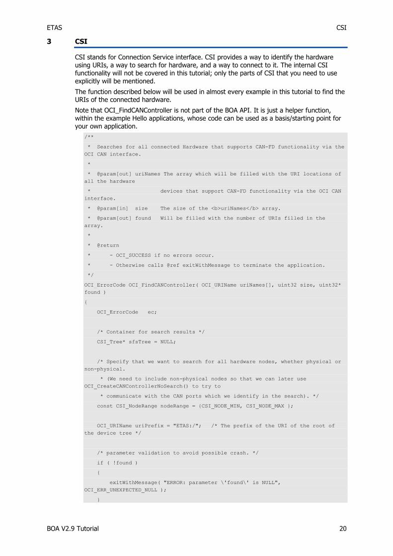
3 CSI
CSI stands for Connection Service interface. CSI provides a way to identify the hardware using URIs, a way to search for hardware, and a way to connect to it. The internal CSI
functionality will not be covered in this tutorial; only the parts of CSI that you need to use
explicitly will be mentioned.
The function described below will be used in almost every example in this tutorial to find the URIs of the connected hardware.
Note that OCI_FindCANController is not part of the BOA API. It is just a helper function,
within the example Hello applications, whose code can be used as a basis/starting point for your own application.
/**
* Searches for all connected Hardware that supports CAN-FD functionality via the
OCI CAN interface.
*
* @param[out] uriNames The array which will be filled with the URI locations of
all the hardware
* devices that support CAN-FD functionality via the OCI CAN
interface.
* @param[in] size The size of the <b>uriNames</b> array.
* @param[out] found Will be filled with the number of URIs filled in the
array.
*
* @return
* - OCI_SUCCESS if no errors occur.
* - Otherwise calls @ref exitWithMessage to terminate the application.
*/
OCI_ErrorCode OCI_FindCANController( OCI_URIName uriNames[], uint32 size, uint32*
found )
{
OCI_ErrorCode ec;
/* Container for search results */
CSI_Tree* sfsTree = NULL;
/* Specify that we want to search for all hardware nodes, whether physical or
non-physical.
* (We need to include non-physical nodes so that we can later use
OCI_CreateCANControllerNoSearch() to try to
* communicate with the CAN ports which we identify in the search). */
const CSI_NodeRange nodeRange = {CSI_NODE_MIN, CSI_NODE_MAX };
OCI_URIName uriPrefix = "ETAS:/"; /* The prefix of the URI of the root of
the device tree */
/* parameter validation to avoid possible crash. */
if ( !found )
{
exitWithMessage( "ERROR: parameter \'found\' is NULL",
OCI_ERR_UNEXPECTED_NULL );
}

ETAS CSI
BOA V2.9 Tutorial 21
/* Search for all connected hardware and latch the result for further
processing */
ec = CSI_CreateProtocolTree( "", nodeRange, &sfsTree );
if ( OCI_FAILED( ec ) )
{
exitWithMessage( "CSI_CreateProtocolTree failed! Error Code: 0x%x\n", ec
);
}
/* Search the tree and fill array with the results */
*found = 0;
findCanNodes( sfsTree, sfsTree, uriPrefix, uriNames, size, found );
/* Clean up the protocol tree. */
ec = CSI_DestroyProtocolTree( sfsTree );
if ( OCI_FAILED( ec ) )
{
exitWithMessage( "CSI_DestroyProtocolTree failed! Error Code: 0x%x\n", ec
);
}
return ec;
}
The function call to CSI_CreateProtocolTree searches for all connected hardware and
drivers and outputs the result as the tree structure sfsTree.
/**
* Recursively scans a tree of CSI nodes created by CSI_CreateProtocolTree() and
* copies the URI-Paths for all devces that support CAN.
*
* @param[in] sfsTree Root of the tree to scan
* @param[in] uriPrefix The prefix which must be added to the URI name of the
* root of the tree in order to create a complete URI.
* @param[out] uriNames The array which will be filled with the URI locations
* of all the hardware devices that support the OCI CAN
* interface.
* @param[in] size The size of the <b>uriNames</b> array.
* @param[out] position The current entry in the <b>uriNames</b> array.
*/
void findCanNodes( CSI_Tree* sfsTree, OCI_URIName uriPrefix, OCI_URIName
uriNames[], uint32 size, uint32* position )
{
/* Uncomment the next line to get a view of the items in the tree */
/* printf( "uriPrefix is %s; node is %s\n", uriPrefix, sfsTree->item.uriNames
); */

ETAS CSI
BOA V2.9 Tutorial 22
/* Basic error checking */
if ( !sfsTree || !uriNames || !uriPrefix || !position )
{
exitWithMessage( "ERROR: parameter is NULL", OCI_ERR_UNEXPECTED_NULL );
}
/* Does the current tree node have the URI name which begins with "CAN:"?
* (Each node which represents a CAN port always has a URI name of the form
"CAN:n". */
if( 0 == strncmp( sfsTree->item.uriName, "CAN:", 4 ) )
{
if (*position < size)
{
strcpy( uriNames[ *position ], uriPrefix );
strcat( uriNames[ *position ], "/" );
strcat( uriNames[ *position ], sfsTree->item.uriName );
(*position)++;
}
else
{
exitWithMessage( "ERROR: Not enough space to list all connected
devices.\n", OCI_ERR_OUT_OF_MEMORY );
}
}
/* If the current tree node has a child, recurse into it */
if (sfsTree->child)
{
OCI_URIName newUriPrefix;
strcpy( newUriPrefix, uriPrefix );
strcat( newUriPrefix, "/" );
strcat( newUriPrefix, sfsTree->item.uriName );
findCanNodes( sfsTree->child, newUriPrefix, uriNames, size, position );
}
/* If the current tree node has a sibling, recurse into it */
if (sfsTree->sibling)
{
findCanNodes( sfsTree->sibling, uriPrefix, uriNames, size, position );
}
}
The next function call, to findCanNodes, searches within the tree for all nodes which
support the OCI_CAN interface. The result is an array of URI names that are added in the
provided uriName array.

ETAS CSI
BOA V2.9 Tutorial 23
In this example code, after extracting the URI names, we do not need the tree structure;
thus, it should be freed using CSI_DestroyProtocolTree. However when you come to
creating the controller a call to OCICreateCANControllerVersion takes time, if the
hardware search has already been done by CSI_CreateProtocolTree and you can be
sure that the hardware configuration has not changed since that time you can use
OCI_CreateCANControllerNoSearch. Look at the use of this command in the
HelloCANFD example code findCanNodes function:
/* Try to open a session of OCI_CAN v1.3 to the CAN port. v1.3 is the oldest
* version of OCI_CAN which supports CAN-FD. */
ec = OCI_CreateCANControllerNoSearch( uriNames[ *position ], &v13, sfsTreeRoot,
&hController );
Please note that size is the size of the uriName array, and found is a uint32 returned
indicating the number items in the array filled in by the CSI_GetUriForUuid.
By changing the UUID_OCICAN to UUID_OCILIN or UUID_OCIFLX, you can search for
different types of hardware that are supported by BOA.

ETAS Creating an OCI application
BOA V2.9 Tutorial 24
4 Creating an OCI application
The following chapters outline how to use the OCI interface in an application. Although ready-to-compile Visual Studio solutions for each bus type are included, the user may also
wish to follow the tutorial through, starting from scratch. The method for setting up your
system to use OCI is shown below.
4.1 How to configure a project from scratch
1. Open a new Visual C++ 2015 project.
2. Right-click the new project, and select Properties.
3. Add *BOA_install_dir\Include\ to your include path.
4. Add *BOA_install_dir\Bin\Win32\Lib to your additional library path (Modify this path according to your system and preferences).
5. Add dll-ocdProxy.lib to your linker’s input additional dependencies.
6. Add dll-csiBind.lib (if you use CSI functionality) to your linker’s input additional
dependencies.
7. Add the directory *BOA_install_dir\Bin\Win32\Dll\Framework to your PATH.
8. Right-click the new project, then select Add New Item and create your new file.
9. You have to include <OCI\oci.h> when using the OCI interface. You also have to include <CSI\csiSfs.h> if you intend to search for attached hardware using the CSI
interface.
10. Fill in your source code.
11. Compile and run your project.
*Where BOA_install_dir is the directory you installed BOA in (e.g. “C:\Program
Files\ETAS\BOA_V2” on 32bit Windows or “C:\Program Files
(x86)\ETAS\BOA_V2” on 64bit Windows).
4.2 Errors and warnings
Opening a session to a controller (for example, by using CreateCANControllerVersion)
can be a failure-prone operation if the application is not set up correctly, and calls to other OCI or BOA API functions may also return errors if certain conditions are not met.
The meanings of these error codes (which are encoded into integers) can be found by
referring to the ocierror.h header file (for OCI errors) or boaerror.h (for BOA errors),
found in the BOA installation under \Include. The Reference Guide, included among the
documentation, also provides useful information about each function and under what conditions it will return certain error codes.
BOA and OCI API functions may also return warnings in some cases. Once again, the
meanings of each warning are contained in either ocierror.h (for OCI warnings) or
boaerror.h (for BOA warnings). A warning indicates that, although the called function was
able to complete the requested operation, some condition arose which was unexpected or which may cause problems in the future. Nevertheless, if the caller wishes he can ignore a
warning, whereas an error should not be ignored.
When a client calls a BOA or OCI API function, he must decide whether he will ignore returned warnings, or whether he will treat them in the same way as errors:
If, when the client calls an API function, he wants to ignore returned warnings then
the client should use one of the macros BOA_SUCCEEDED() or OCI_SUCCEEDED()
to evaluate the function’s return code. These macros are defined in boaerror.h
and ocierror.h respectively and evaluate to false if their argument is an error,
and true otherwise.

ETAS Creating an OCI application
BOA V2.9 Tutorial 25
If, when the client calls an API function, he wants to treat returned warnings as
errors then the client should compare the function’s return code to BOA_SUCCESS
(for BOA APIs) or OCI_SUCCESS (for OCI APIs).
For example:
/* Ignore warnings from OCI_DoSomething() */
if( OCI_SUCCEEDED( OCI_DoSomething() ) )
{
/* This branch will be executed if OCI_DoSomething() returns successfully
or with a warning */
}
else
{
/* This branch will only be executed if OCI_DoSomething() returns an error */
}
...
/* Treat warnings from OCI_DoSomethingElse() as errors */
if( OCI_SUCCESS == OCI_DoSomethingElse() )
{
/* This branch will only be executed if OCI_DoSomethingElse() returns
successfully */
}
else
{
/* This branch will be executed if OCI_DoSomethingElse() returns an error
or a warning */
}
Clients are advised to consider carefully which of these two approaches to adopt. Treating warnings as errors can lead to problems if a later version of BOA adds new warnings to
previously-successful function calls. On the other hand, ignoring warnings can mean that potential problems are also ignored.
4.3 Troubleshooting
For more help on common problems, refer to the User’s Guide section on troubleshooting.

ETAS OCI_CAN and CAN-FD
BOA V2.9 Tutorial 26
5 OCI_CAN and CAN-FD
This chapter provides a step-by-step sample implementation to get you started with OCI on the CAN bus. A sample project is also included, which is ready-to-compile in Visual Studio.
BOA models CAN-FD as an extension of the OCI_CAN controller concept. CAN-FD is available
from OCI_CAN API version 1.3.0.0.
5.1 Minimal Implementation
In this example, the smallest possible OCI implementation for CAN buses is presented. This implementation will show how to use OCI to send/receive messages over a CAN bus using
the minimum amount of code. The example will consist of three main parts: Configuring
the device, Sending frames and Receiving frames. Sending and receiving are described separately for the sake of clarity. Take note that, should you wish to both send
and receive data at the same time, you will need to open two controllers on two different bus nodes.
5.1.1 Configuring the Device
Create a controller handle
An OCI_ControllerHandle represents a hardware device in OCI. This handle is used by
OCI to identify a controller. To create a valid OCI_ControllerHandle you need to have
the URI of the device you want to create a handle for. You will either know the URI of the
device you want to create a handle for, or you can acquire that information by searching for all available CAN devices then selecting one of them (see Chapter 3, CSI, on page 20 for
more details). Use the factory function OCI_CreateCANControllerVersion to create
the controller handle, or if the hardware search has already been done by CSI_CreateProtocolTree and you can be sure that the hardware configuration has not
changed since that time you can use the faster OCI_CreateCANControllerNoSearch
function. The function requires an OCI_URIName (or char*), a BOA_Version, and in the
case of OCI_CreateCANControllerNoSearch a pointer to the tree created by
CSI_CreateProtocolTree as input.
The version parameter specifies which version of the API you would like to use. From time-
to-time, ETAS may modify one of the OCI APIs (e.g. to add new functionality), but obviously older hardware devices will not support these modifications. So how can your application
discover whether it is safe to use a particular feature of an OCI API?
To solve this problem, each new version of each OCI API is assigned a version number, and your OCI client application must negotiate with the connected hardware device in order to
discover an API version which both can understand. This must be done by following these
steps:
1. You must decide which version of your chosen OCI API your application needs to
use. Most OCI API features have been present since v1.0.0.0 of the relevant API,
but a few have been added in subsequent API versions, and in such cases this will be indicated in the reference documentation. CAN-FD capability was added in
v1.3.0.0 of OCI-CAN.
In general, you should choose the oldest version which you think is acceptable to your application, in order to maximize compatibility with older hardware devices.
2. You should call OCI_CreateCANControllerVersion(), specifying your chosen
API version. If this is successful, you do not need to take any further steps. However if you are wanting to use CAN-FD, bear in mind that API V1.3.0.0 enables the
support for CAN-FD – it does not guarantee it, so as well as specifying a minimum version of 1.3.0.0 you will need to check that your chosen controller does actually
support CAN-FD. This can be done by calling
ETAS OCI_CAN and CAN-FD
BOA V2.9 Tutorial 27
OCI_GetCANControllerCapabilities() and examining the
OCI_CANControllerCapabilities structure returned.
3. However, OCI_CreateCANControllerVersion() may return
OCI_ERR_PROTOCOL_VERSION_NOT_SUPPORTED, which means that your chosen
hardware device does not support the API version you chose in step 1. If this
occurs, you must choose an older API version and try step 2 again.
4. Eventually, you will find an API version which is accepted by your chosen hardware
device. Your application must now abide by the limitations of this API version! Continuing the example of CAN-FD capability mentioned in step 1, if you originally
chose OCI_CAN v1.3.0.0 in step 1 but had to revert to v1.0.0.0 in step 3 then your application must not refer to any fields introduced in later versions such as
busParticipationMode, canFDEnabled, canFDConfig in the
OCI_CANConfiguration struct .
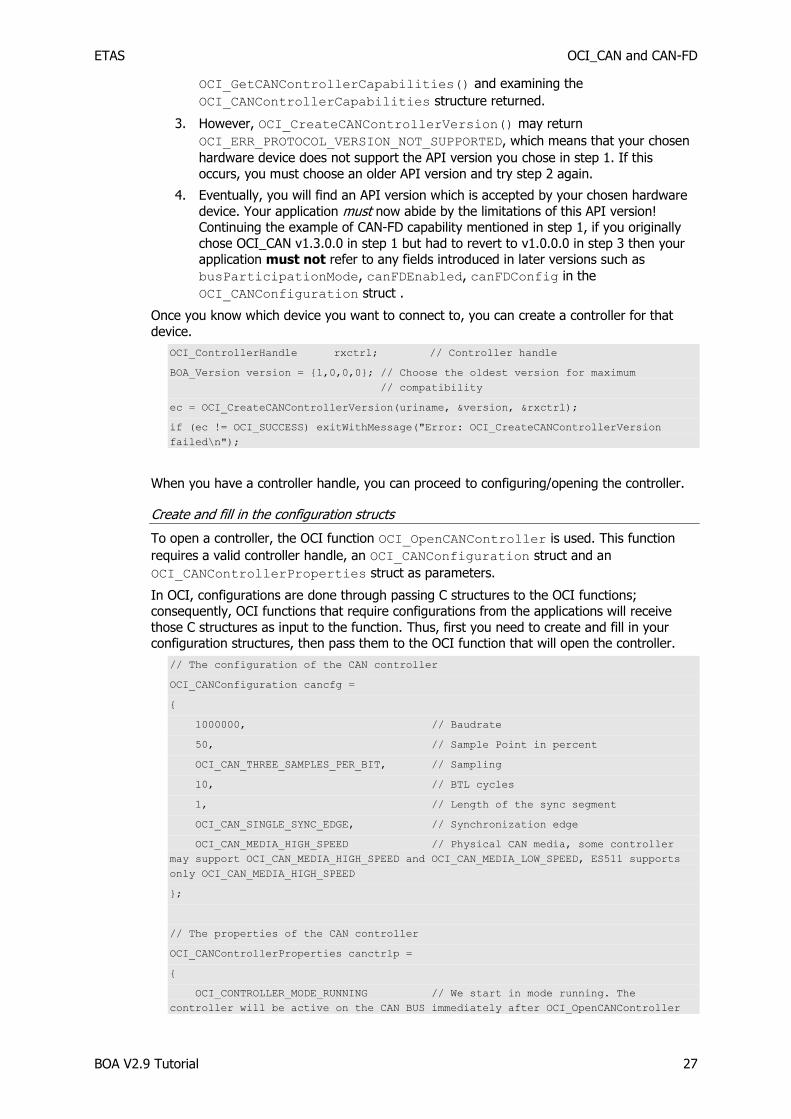
Once you know which device you want to connect to, you can create a controller for that
device.
OCI_ControllerHandle rxctrl; // Controller handle
BOA_Version version = {1,0,0,0}; // Choose the oldest version for maximum
// compatibility
ec = OCI_CreateCANControllerVersion(uriname, &version, &rxctrl);
if (ec != OCI_SUCCESS) exitWithMessage("Error: OCI_CreateCANControllerVersion
failed\n");
When you have a controller handle, you can proceed to configuring/opening the controller.
Create and fill in the configuration structs
To open a controller, the OCI function OCI_OpenCANController is used. This function
requires a valid controller handle, an OCI_CANConfiguration struct and an
OCI_CANControllerProperties struct as parameters.
In OCI, configurations are done through passing C structures to the OCI functions; consequently, OCI functions that require configurations from the applications will receive
those C structures as input to the function. Thus, first you need to create and fill in your configuration structures, then pass them to the OCI function that will open the controller.
// The configuration of the CAN controller
OCI_CANConfiguration cancfg =
{
1000000, // Baudrate
50, // Sample Point in percent
OCI_CAN_THREE_SAMPLES_PER_BIT, // Sampling
10, // BTL cycles
1, // Length of the sync segment
OCI_CAN_SINGLE_SYNC_EDGE, // Synchronization edge
OCI_CAN_MEDIA_HIGH_SPEED // Physical CAN media, some controller
may support OCI_CAN_MEDIA_HIGH_SPEED and OCI_CAN_MEDIA_LOW_SPEED, ES511 supports
only OCI_CAN_MEDIA_HIGH_SPEED
};
// The properties of the CAN controller
OCI_CANControllerProperties canctrlp =
{
OCI_CONTROLLER_MODE_RUNNING // We start in mode running. The
controller will be active on the CAN BUS immediately after OCI_OpenCANController

ETAS OCI_CAN and CAN-FD
BOA V2.9 Tutorial 28
};
Open the controller
An OCI controller can exist in one of three modes: CREATED, SUSPENDED, and RUNNING. A
new controller is always in the CREATED mode after creation. Afterwards, when you open
the controller, you can choose in which mode it will move to, either SUSPENDED or
RUNNING based on the configurations in the OCI_CANControllerProperties. A
controller in the SUSPENDED mode will not interact with the bus until you move it to the
RUNNING mode (see Section 2.2.3, Controllers, on page 10 for more details).
Since you already have all configuration structs ready, the only step left is to pass those structs to the function that will open and configure the controller.
// Open and configure the controller
ec = OCI_OpenCANController(rxctrl, &cancfg, &canctrlp);
if (ec != OCI_SUCCESS) exitWithMessage("Error: OCI_OpenCANController failed\n");
Now you have a controller that is open and configured. The controller is now nearly ready to
send and receive data. Nevertheless, before you can do that, you need to setup transmit and receive queues respectively. This is done through the functions
OCI_CreateCANTxQueue and OCI_CreateCANRxQueue.
5.1.2 Sending
Currently, transmit queues’ configuration structure is a dummy holding place that might be needed in the future; you just need to create it, initialize it to zero and pass it to the
function. Again, like creating the controller, you need an OCI_QueueHandle to enable
referencing this queue later, possibly for removal or other modifications.
OCI_QueueHandle txqueue; // Transmitter Queue handle
// The configuration for the transmit queue
OCI_CANTxQueueConfiguration txcfg =
{
0 // Reserved for future extension should be set to 0 to avoid problems
};
// Create a transmit queue. Any data transmission will be done through this queue
ec = OCI_CreateCANTxQueue(txctrl, &txcfg, &txqueue);
if (ec != OCI_SUCCESS) exitWithMessage("Error: OCI_CreateCANTxQueue failed\n");
Once you have the transmit queue set, you are ready to start putting messages/frames in
that queue. First, you have to construct the messages, then, add them to the transmit queue. A code example on how to create a CAN message and place it in the transmit queue
can be found below (see 2.2.5, Messages, on page 13 for more details).
OCI_CANMessage canMessages[2]; // Array of can messages
OCI_CANTxMessage msg0 =
{
0x0101, // CAN frame ID.
OCI_CAN_MSG_FLAG_EXTENDED, // we use an extended Identifier here
0, // Reserved must be set to 0
7, // DLC: Number of (valid) data bytes.
"Hello " // payload

ETAS OCI_CAN and CAN-FD
BOA V2.9 Tutorial 29
};
OCI_CANTxMessage msg1 =
{
0x0102, // CAN frame ID.
OCI_CAN_MSG_FLAG_EXTENDED, // we use use an extended Identifier here
0, // Reserved must be set to 0
7, // DLC: Number of (valid) data bytes.
"World! " // payload
};
// copy the message data into the transmit structure.
canMessages[0].type = OCI_CAN_TX_MESSAGE;
canMessages[0].reserved = 0;
memcpy(&canMessages[0].data.txMessage, &msg0, sizeof(OCI_CANTxMessage));
canMessages[1].type = OCI_CAN_TX_MESSAGE;
canMessages[1].reserved = 0;
memcpy(&canMessages[1].data.txMessage, &msg1, sizeof(OCI_CANTxMessage));
// Write the messages to the transmit queue
ec = OCI_WriteCANData(txqueue, OCI_NO_TIME, canMessages, 2, NULL);
if (ec != OCI_SUCCESS) exitWithMessage("Error: OCI_WriteCANData failed\n");
5.1.3 Receiving
The receive queue on the other hand is a little more complex, as it will need to notify your application upon the reception of frames. The simplest way to achieve that in OCI is by
assigning callbacks to be called upon the reception of a frame or upon the occurrence of an
event. Another way, of doing that is using events to notify your application when queue handling is needed. Then your application should fetch the data from the queue manually.
One more choice that has to be made for the receive queue is whether the frames sent from the same controller should be queued as received or not (self-reception).
The reference guide should be checked for further details about the callbacks, the function
signatures, etc.
// The configuration for the receive queue
OCI_CANRxQueueConfiguration rxcfg =
{
{ RxFrameCallback, //Callback that is triggered, whenever a CAN frame is
// received and passes the filter condition
NULL }, // This value will be passed to the callback whenever it’s called
{ RxEventCallback, //Callback that is triggered, whenever an event occurs
NULL }, // This value will be passed to the callback whenever it’s called
OCI_SELF_RECEPTION_OFF // We do not want to receive frames that we transmit
};
OCI_QueueHandle rxqueue; // Receive Queue handle
// Create a receive queue. We register callbacks for frame reception and events.
These callbacks are triggered whenever a frame is received and passes the filter
condition, or when an event occurs.

ETAS OCI_CAN and CAN-FD
BOA V2.9 Tutorial 30
ec = OCI_CreateCANRxQueue(rxctrl, &rxcfg, &rxqueue);
if (ec != OCI_SUCCESS) exitWithMessage("Error: OCI_CreateCANRxQueue failed\n");
Unfortunately, you are not able to receive frames yet. By default, OCI drops all frames
unless they match a filter assigned to a specific queue. Therefore, in order to be able to
receive some frames, you need to create a filter that will accept the frames you want to receive. In this tutorial, an All-Pass filter is used; this filter will accept all the frames on the
bus. You need to assign that filter to your receive queue.
// Array of filter conditions used by the example. We use a single 'all-pass'
filter
OCI_CANRxFilter filter[] =
{
{ 0, //frameIDValue - The ID of a received frame ANDed with frameIDMask
//will be compared against this value
0, //frameIDMask - The ID of a received frame will be ANDed with this
//value (will always result in 0 in this example)
0 //This value will be attached to the message if it matches this filter
}
};
// The receive queue will not receive any data until we have defined some white
filter. Here we allow any CAN frame to pass the filter. So we receive all frames
from the CAN-Bus
ec = OCI_AddCANFrameFilter(rxqueue, filter, 1); //add the filter to the queue
if (ec != OCI_SUCCESS) exitWithMessage("Error: OCI_AddCANFrameFilter failed\n");
Now, only one thing has to be done: specify the behavior upon the reception of a frame. As mentioned before, this is done using callback functions. You should have already specified
the name of your callback; all that is remains is the implementation. As mentioned before, when a callback is defined messages are delivered to that function rather than placed in a
queue. Below is a sample implementation for the callback function. This implementation
simply prints out the payload of the CAN frame.
// Callback for processing received CAN Frames. Here we simply check the message
type and print the payload
static void RxFrameCallback (void *userData, struct OCI_CANMessage* msg)
{
if (msg->type == OCI_CAN_RX_MESSAGE)
{
printf ("%s",msg->data.rxMessage.data);
}
}
// Callback for processing received events. We do not handle any event in this
example and just exit with an error message. This routine should never be called.
To receive events, we must define white filter for the events in the same way, as
we did for messages (see OCI_AddCANEventFilter(), OCI_AddTimerEventFilter(), ...)
static void RxEventCallback (void *userData, struct OCI_CANMessage* msg)
{
exitWithMessage ("unexpected event received\n");
}

ETAS OCI_CAN and CAN-FD
BOA V2.9 Tutorial 31
Note
Remember to wait for messages to arrive!
Remember to tell your main thread to wait after setting everything for reception and before destroying the controller, otherwise the program will quit/destroy the controller immediately and of course will not be able to receive anything. This can be done any way you like, e.g. using Sleep() statements, or waiting for keyboard inputs.
Close the controller
The OCI controller is owned by the application, thus it is your job to destroy the controller after you have finished using it. However, you do not need to explicitly destroy everything
else since OCI will destroy anything associated with that controller when destroying the
controller itself. You can destroy a controller very easily by including something similar to the following code.
ec = OCI_DestroyCANController(rxctrl);
if (ec != OCI_SUCCESS) exitWithMessage("Error: OCI_DestroyCANController
failed\n");
5.2 Working example : HelloCAN_OCI, HelloCANFD
Two complete, ready-to-run examples are included in the installation directory at Examples\EBI-IP_Examples.zip\HelloCAN_OCI\HelloCAN_OCI.sln and
Examples\EBI-IP_Examples.zip\HelloCANFD\HelloCANFD.sln. Each example is
split into two projects (one for transmit, one for receive) covering all of the topics discussed in this section, and will allow you to quickly build a working application that uses the OCI
interface with CAN or CAN-FD hardware.
5.2.1 Operation
To use the example, open the solution in Visual Studio, then build and run one of the projects.
Where possible, the examples follow the same basic format and use a similar style to the
code that has been shown throughout this tutorial.
Both projects start by searching for attached hardware. Any OCDs present in the default OCDs folder will be enumerated. Choose an OCD by typing its number and pressing enter.
A controller will be created using the URI of the OCD selected, and then opened.
A queue (Tx or Rx depending on which project was chosen) will then be created on this
controller. If a receive queue was created, a white filter will be added to it to allow all incoming messages to be received.
The program will then operate on the queue in a typical way, demonstrating how to use it.
If the example uses a transmit queue, it will write data to the bus. If a receive queue is
used, it will wait for messages from the bus. Press enter to halt transmission/reception.
The controller (and its associated queue) will then be destroyed, and the program will exit.
If the OCD returns an error at any point, the program will exit with an error message.
ETAS OCI_FLEXRAY
BOA V2.9 Tutorial 32
6 OCI_FLEXRAY
This chapter provides a step-by-step sample implementation to get you started with OCI on the FlexRay bus. A sample project is also included, which is ready-to-compile in Visual
Studio.
6.1 Minimal Implementation:
In this example, the smallest possible OCI implementation for FlexRay buses is presented.
This implementation will show how to use OCI to send/receive messages over a FlexRay bus using the minimum amount of code. The example will consist of three main parts:
Configuring the device and Sending frames and Receiving frames. Sending and
receiving are described separately for the sake of clarity. Take note that, should you wish to both send and receive data at the same time, you will need to open two controllers on two
different bus nodes.
6.1.1 Configuring the Device
Create a controller handle
An OCI_ControllerHandle represents a hardware device in OCI. This handle is used by
OCI to identify a controller. To create a valid OCI_ControllerHandle you need to have
the URI of the device you want to create a handle for. You will either know the URI of the
device you want to create a handle for, or you can acquire that information by searching for
all available FlexRay devices then selecting one of them (see Chapter 3, CSI, on page 20 for
more details). Use the factory function OCI_CreateFlexRayControllerVersion to
create the controller handle, or if the hardware search has already been done by CSI_CreateProtocolTree and you can be sure that the hardware configuration has not
changed since that time you can use the faster
OCI_CreateFlexRayControllerNoSearch function. The function requires an
OCI_URIName (or char*), a BOA_Version, and in the case of
OCI_CreateFlexRayControllerNoSearch a pointer to the tree created by
CSI_CreateProtocolTree as input.
The version parameter specifies which version of the API you would like to use. From time-to-time, ETAS may modify one of the OCI APIs (e.g. to add new functionality), but obviously
older hardware devices will not support these modifications. So how can your application discover whether it is safe to use a particular feature of an OCI API?
To solve this problem, each new version of each OCI API is assigned a version number, and
your OCI client application must negotiate with the connected hardware device in order to discover an API version which both can understand. This must be done by following these
steps:
1. You must decide which version of your chosen OCI API your application needs to use. Most OCI API features have been present since v1.0.0.0 of the relevant API,
but a few have been added in subsequent API versions, and in such cases this will
be indicated in the reference documentation
2. In general, you should choose the oldest version which you think is acceptable to your application, in order to maximize compatibility with older hardware devices.
3. You should call OCI_CreateFlexRayControllerVersion(), specifying your
chosen API version. If this is successful, you do not need to take any further steps.
4. However, OCI_CreateFlexRayControllerVersion() may return
OCI_ERR_PROTOCOL_VERSION_NOT_SUPPORTED, which means that your chosen
hardware device does not support the API version you chose in step 1. If this
occurs, you must choose an older API version and try step 2 again.
5. Eventually, you will find an API version which is accepted by your chosen hardware device. Your application must now abide by the limitations of this API version!

ETAS OCI_FLEXRAY
BOA V2.9 Tutorial 33
Once you know which device you want to connect to, you can create a controller for that
device.
OCI_ControllerHandle rxctrl; // Controller handle
BOA_Version version = {1,0,0,0};
ec = OCI_CreateFlexRayControllerVersion (uriname[1], &version, &rxctrl);
if (ec != OCI_SUCCESS) exitWithMessage("Error: OCI_CreateFlexRayControllerVersion
failed\n");
As soon as you have a controller handle, you can proceed to configuring/opening the controller.
Create and fill in the configuration structs
To open a controller, the OCI function OCI_OpenFlexRayController is used. This
function requires a valid controller handle, an OCI_FlexRayConfiguration and an
OCI_FlexRayControllerProperties structures as parameters.
In OCI, configurations are done through passing C structures to the OCI functions; consequently, OCI functions that require configurations from the applications will receive
those C structures as input to the function. Thus, first you need to create and fill in your
configuration structures, then pass them to the OCI function that will open the controller.
OCI_FlexRayControllerProperties prop; // Properties of the FlexRay controller
prop.mode = OCI_CONTROLLER_MODE_RUNNING;
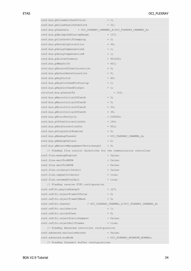
OCI_FlexRayConfiguration conf; // FlexRay configuration struct
// set configuration tree
conf.bus.gColdStartAttempts = 31;
conf.bus.gdActionPointOffset = 3;
conf.bus.gdCASRxLowMax = 81;
conf.bus.gdDynamicSlotIdlePhase = 1;
conf.bus.gdMinislot = 7;
conf.bus.gdMinislotActionPointOffset = 3;
conf.bus.gdStaticSlot = 47;
conf.bus.gdSymbolWindow = 0;
conf.bus.gdTSSTransmitter = 8;
conf.bus.gdWakeupSymbolRxIdle = 59;
conf.bus.gdWakeupSymbolRxLow = 53;
conf.bus.gdWakeupSymbolRxWindow = 301;
conf.bus.gdWakeupSymbolTxIdle = 180;
conf.bus.gdWakeupSymbolTxLow = 60;
conf.bus.gListenNoise = 16;
conf.bus.gMacroPerCycle = 5000;
conf.bus.gMaxWithoutClockCorrectionFatal = 15;
conf.bus.gMaxWithoutClockCorrectionPassive = 15;
conf.bus.gNumberOfMinislots = 161;
conf.bus.gNumberOfStaticSlots = 80;
conf.bus.gOffsetCorrectionStart = 4992;
conf.bus.gPayloadLengthStatic = 15;
conf.bus.gSyncNodeMax = 15;
ETAS OCI_FLEXRAY
BOA V2.9 Tutorial 34
conf.bus.pAllowHaltDueToClock = 1;
conf.bus.pAllowPassiveToActive = 31;
conf.bus.pChannels = OCI_FLEXRAY_CHANNEL_A|OCI_FLEXRAY_CHANNEL_B;
conf.bus.pdAcceptedStartupRange = 137;
conf.bus.pClusterDriftDamping = 2;
conf.bus.pDecodingCorrection = 44;
conf.bus.pDelayCompensationA = 1;
conf.bus.pDelayCompensationB = 1;
conf.bus.pdListenTimeout = 401202;
conf.bus.pdMaxDrift = 601;
conf.bus.pExternOffsetCorrection = 0;
conf.bus.pExternRateCorrection = 0;
conf.bus.pKeySlotId = 40;
conf.bus.pKeySlotUsedForStartup = 1;
conf.bus.pKeySlotUsedForSync = 1;
ctrlConf.bus.pLatestTx = 122;
conf.bus.pMacroInitialOffsetA = 5;
conf.bus.pMacroInitialOffsetB = 5;
conf.bus.pMicroInitialOffsetA = 35;
conf.bus.pMicroInitialOffsetB = 35;
conf.bus.pMicroPerCycle = 200000;
conf.bus.pOffsetCorrectionOut = 145;
conf.bus.pRateCorrectionOut = 601;
conf.bus.pSingleSlotEnabled = 0;
conf.bus.pWakeupChannel = OCI_FLEXRAY_CHANNEL_A;
conf.bus.pWakeupPattern = 2;
conf.bus.gNetworkManagementVectorLength = 0;
// FlexRay flow control directives for the communication controller
conf.flow.wakeupEnabled = false;
conf.flow.waitForWUPA = false;
conf.flow.waitForWUPB = false;
conf.flow.coldstartInhibit = false;
conf.flow.repeatColdstart = true;
conf.flow.resumeAfterHalt = true;
// FlexRay receive FIFO configuration
conf.rxFifo.payloadLength = 127;
conf.rxFifo.rejectFrameIDValue = 0;
conf.rxFifo.rejectFrameIDMask = 0;
conf.rxFifo.channel = OCI_FLEXRAY_CHANNEL_A|OCI_FLEXRAY_CHANNEL_B;
conf.rxFifo.cyclePeriod = 1;
conf.rxFifo.cycleOffset = 0;
conf.rxFifo.rejectStaticSegment = false;
conf.rxFifo.rejectNullFrames = true;
// FlexRay Advanced controller configuration
conf.advanced.exclusiveAccess = false;
conf.advanced.busMode = OCI_FLEXRAY_BUSMODE_NORMAL;
// FlexRay Transmit buffer configurations
ETAS OCI_FLEXRAY
BOA V2.9 Tutorial 35
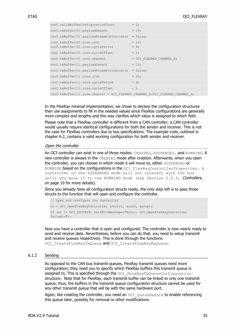
conf.validBufferConfigurationCount = 2;
conf.txBuffer[0].payloadLength = 15;
conf.txBuffer[0].payloadPreambleIndicator = false;
conf.txBuffer[0].core.slot = 10;
conf.txBuffer[0].core.cyclePeriod = 4;
conf.txBuffer[0].core.cycleOffset = 1;
conf.txBuffer[0].core.channel = OCI_FLEXRAY_CHANNEL_A;
conf.txBuffer[1].payloadLength = 15;
conf.txBuffer[1].payloadPreambleIndicator = false;
conf.txBuffer[1].core.slot = 20;
conf.txBuffer[1].core.cyclePeriod = 4;
conf.txBuffer[1].core.cycleOffset = 2
conf.txBuffer[1].core.channel = OCI_FLEXRAY_CHANNEL_A|OCI_FLEXRAY_CHANNEL_B;
In the FlexRay minimal implementation, we chose to declare the configuration structures
then use assignments to fill in the needed values since FlexRay configurations are generally more complex and lengthy and this way clarifies which value is assigned to which field.
Please note that a FlexRay controller is different from a CAN controller; a CAN controller
would usually require identical configurations for both the sender and receiver. This is not the case for FlexRay controllers due to bus specifications. The example code, outlined in
chapter 6.2, contains a valid working configuration for both sender and receiver.
Open the controller
An OCI controller can exist in one of three modes: CREATED, SUSPENDED, and RUNNING. A
new controller is always in the CREATED mode after creation. Afterwards, when you open
the controller, you can choose in which mode it will move to, either SUSPENDED or
RUNNING based on the configurations in the OCI_FlexRayControllerProperties. A controller in the SUSPENDED mode will not interact with the bus
until you move it to the RUNNING mode (see Section 2.2.3, Controllers,
on page 10 for more details).
Since you already have all configuration structs ready, the only step left is to pass those
structs to the function that will open and configure the controller.
// Open and configure the controller
ec = OCI_OpenFlexRayController (rxctrl, &conf, &prop);
if (ec != OCI_SUCCESS) exitWithMessage("Error: OCI_OpenFlexRayController
failed\n");
Now you have a controller that is open and configured. The controller is now nearly ready to send and receive data. Nevertheless, before you can do that, you need to setup transmit
and receive queues respectively. This is done through the functions
OCI_CreateFlexRayTxQueue and OCI_CreateFlexRayRxQueue.
6.1.2 Sending
As opposed to the CAN bus transmit queues, FlexRay transmit queues need more
configuration; they need you to specify which FlexRay buffers this transmit queue is
assigned to. This is specified through the OCI_FlexRayTxQueueConfiguration
structure. Note that for FlexRay, each transmit buffer can be linked to only one transmit
queue; thus, the buffers in the transmit queue configuration structure cannot be used for
any other transmit queue that will be with the same hardware port.
Again, like creating the controller, you need an OCI_QueueHandle to enable referencing
this queue later, possibly for removal or other modifications.

ETAS OCI_FLEXRAY
BOA V2.9 Tutorial 36
OCI_QueueHandle txqueue; // Transmitter Queue handle
OCI_FlexRayTxQueueConfiguration txq_conf; // Transmit queue configurations
txq_conf.count = 1;
txq_conf.bufferIndexes[0] = 1;
// Create a transmit queue
ec = OCI_CreateFlexRayTxQueue (txctrl, &txq_conf, &txqueue);
if (ec != OCI_SUCCESS) exitWithMessage("Error: OCI_CreateFlexRayTxQueue
failed\n");
Once you have the transmit queue set, you are ready to start putting messages/frames in
that queue. First, you have to construct the messages, then, add them to the transmit queue. A code example on how to create a FlexRay message and place it in the transmit
queue can be found below (see 2.2.5, Messages, on page 13 for more details).
OCI_FlexRayMessage msg;
msg.type = OCI_FLEXRAY_TX_MESSAGE;
msg.data.txMessage.flags = 0;
msg.data.txMessage.size = (uint8) 13;
strcpy(msg.data.txMessage.data, “Hello World!\0”);
// Write the messages to the transmit queue
ec = OCI_WriteFlexRayData (txqueue, 0, &msg, 1, NULL);
if (ec != OCI_SUCCESS) exitWithMessage("Error: OCI_WriteFlexRayData failed\n");
6.1.3 Receiving
The receive queue on the other hand is a little more complex since it will need to notify your
application upon the reception of frames. The simplest way to achieve that in OCI is by assigning callbacks to be called upon the reception of a frame or upon the occurrence of an
event. Another way of doing that is using events to notify your application when queue handling is needed. Then your application should fetch the data from the queue manually.
One more choice that has to be made for the receive queue is whether the frames sent from
the same controller should be queued as received or not (self-reception).
The reference guide should be checked for further details about the callbacks, the function
signatures, etc.
// The configuration for the receive queue
OCI_FlexRayRxQueueConfiguration rxq_conf;
rxq_conf.onEvent.function = RxEventCallback;
rxq_conf.onEvent.userData = NULL;
rxq_conf.onFrame.function = RxFrametCallback;
rxq_conf.onFrame.userData = NULL;
rxq_conf.selfReceptionMode = OCI_SELF_RECEPTION_OFF;
OCI_QueueHandle rxqueue; // Receive Queue handle
// Create a receive queue. We register callbacks for frame reception and events.
These callbacks are triggered whenever a frame is received and passes the filter
condition, or when an event occurs.
ec = OCI_CreateFlexRayRxQueue (rxctrl, &rxq_conf, &rxqueue);
if (ec != OCI_SUCCESS) exitWithMessage("Error: OCI_CreateFlexRayRxQueue
failed\n");

ETAS OCI_FLEXRAY
BOA V2.9 Tutorial 37
Unfortunately, you are not able to receive frames as of yet. By default, OCI drops all frames
unless they match a filter assigned to a specific queue. Therefore, in order to be able to
receive some frames, you need to create a filter that will accept the frames you want to receive. In this tutorial, an All-Pass filter is used; this filter will accept all the frames on the
bus. You need to assign that filter to your receive queue.
OCI_FlexRayRxFilter filter[1]; // FlexRayRxFilter array
//Create a white filter for any message
filter[0].frameIDMask = 0;
filter[0].frameIDValue = 0;
filter[0].ccIndicators = OCI_FLEXRAY_CHANNEL_A | OCI_FLEXRAY_CHANNEL_B;
filter[0].cyclePeriod = 1;
filter[0].cycleOffset = 0;
filter[0].tag = 1111;
// The receive queue will not receive any data until we have defined some white
// filter. Here we allow any FlexRay frame to pass the filter. So we receive all
// frames from the FlexRay-Bus
ec = OCI_AddFlexRayFrameFilter(rxqueue, filter, 1);
if (ec != OCI_SUCCESS) exitWithMessage("Error: OCI_AddFlexRayFrameFilter
failed\n");
Now, only one thing has to be done: specify the behavior upon the reception of a frame. As
mentioned before, this is done using callback functions. You should have already specified
the name of your callback; all that is remains is the implementation. As mentioned before, when a callback is defined messages are delivered to that function rather than placed in a
queue. Below is a sample implementation for the callback function. This implementation simply prints out the payload of the FlexRay frame.
// Callback for processing received Frames.
static void OCI_CALLBACK RxFrameCallback (void *userData, OCI_FlexRayMessage *msg)
{
if (msg->type == OCI_FlexRay_RX_MESSAGE)
{
printf("Message Received:\n");
printf("Message Data: #%s#\n", msg->data.rxMessage.data);
printf("Timestamp %lld\n", msg->data.rxMessage.timeStamp);
printf("FrameID: %d\nChannel: %d\n", msg->data.rxMessage.frameID,
msg->data.rxMessage.ccIndicators);
}
}
// Callback for processing received events. We do not handle any event in this
// example and just exit with an error message. This routine should never be
// called. To receive events, we must define white filter for the events in the
// same way, as we did for messages (see OCI_AddFlexRayEventFilter(),
// OCI_AddTimerEventFilter(), ...)
static void RxEventCallback (void *userData, struct OCI_FlexRayMessage* msg) //
Receiver event callback function
{
exitWithMessage ("Unexpected event received\n");
}

ETAS OCI_FLEXRAY
BOA V2.9 Tutorial 38
Note
Remember to wait for messages to arrive!
Remember to tell your main thread to wait after setting everything for reception and before destroying the controller, otherwise the program will quit/destroy the controller immediately and of course will not be able to receive anything. This can be done any way you like, e.g. using Sleep() statements, or waiting for keyboard inputs.
Close the controller
The OCI controller is owned by the application, thus it is your job to destroy the controller after you have finished using it. However, you do not need to explicitly destroy everything
else since OCI will destroy anything associated with that controller when destroying the
controller itself. You can destroy a controller very easily by including something similar to the following code.
ec = OCI_DestroyFlexRayController(rxctrl);
if (ec != OCI_SUCCESS) exitWithMessage("Error: OCI_DestroyFlexRayController
failed\n");
6.2 Working example : HelloFLX_OCI
A complete, ready-to-run example is included in the installation directory at
Examples\EBI-IP_Examples.zip\HelloFLX_OCI\HelloFLX_OCI.sln. The example
is split into two projects (one for transmit, one for receive) covering all of the topics
discussed in this section, and will allow you to quickly build a working application that uses the OCI interface with FlexRay hardware.
6.2.1 Operation
To use the example, open the solution in Visual Studio, then build and run one of the
projects.
Where possible, the examples follow the same basic format and use a similar style to the code that has been shown throughout this tutorial.
Both projects start by searching for attached hardware. Any OCDs present in the default
OCDs folder will be enumerated. Choose an OCD by typing its number and pressing enter.
A controller will be created using the URI of the OCD selected, and then opened.
A queue (Tx or Rx depending on which project was chosen) will then be created on this controller. If a receive queue was created, a white filter will be added to it to allow all
incoming messages to be received.
The program will then operate on the queue in a typical way, demonstrating how to use it. If the example uses a transmit queue, it will write data to the bus. If a receive queue is
used, it will wait for messages from the bus. Press enter to halt transmission/reception.
The controller (and its associated queue) will then be destroyed, and the program will exit.
If the OCD returns an error at any point, the program will exit with an error message.

ETAS OCI_LIN
BOA V2.9 Tutorial 39
7 OCI_LIN
This chapter provides a step-by-step sample implementation to get you started with OCI on the LIN bus. A sample project is also included, which is ready-to-compile in Visual Studio.
7.1 Minimal Implementation
In this example, the smallest possible OCI implementation for LIN buses is presented. This implementation will show how to use OCI to implement a LIN bus master, slave and
monitoring nodes using the minimum amount of code. An individual example would consist of four main parts: Configuring the Device followed by LIN Master, LIN Slave, and
LIN Monitoring. This example has a different structure to the others due to the
specifications of the LIN bus. This structure allows a clear separation between the different usage scenarios one might want to achieve with a LIN bus node. Take note that, should you
wish to both send and receive data at the same time, you will need a combination of Master, Slaves or Monitors on different bus nodes.
7.1.1 Configuring the Device
Create a controller handle
An OCI_ControllerHandle represents a hardware device in OCI. This handle is used by
OCI to identify a controller. To create a valid OCI_ControllerHandle you need to have
the URI of the device you want to create a handle for. You will either know the URI of the
device you want to create a handle for, or you can acquire that information by searching for all available LIN devices then selecting one of them (see Chapter 3, CSI, on page 20 for
more details). Use the factory function OCI_CreateLINControllerVersion to create
the controller handle, or if the hardware search has already been done by CSI_CreateProtocolTree and you can be sure that the hardware configuration has not
changed since that time you can use the faster OCI_CreateLINControllerNoSearch
function. The function requires an OCI_URIName (or char*), a BOA_Version, and in the
case of OCI_CreateLINControllerNoSearch a pointer to the tree created by
CSI_CreateProtocolTree as input.
The version parameter specifies which version of the API you would like to use. From time-
to-time, ETAS may modify one of the OCI APIs (e.g. to add new functionality), but obviously older hardware devices will not support these modifications. So how can your application
discover whether it is safe to use a particular feature of an OCI API?
To solve this problem, each new version of each OCI API is assigned a version number, and your OCI client application must negotiate with the connected hardware device in order to
discover an API version which both can understand. This must be done by following these
steps:
1. You must decide which version of your chosen OCI API your application needs to
use. Most OCI API features have been present since v1.0.0.0 of the relevant API,
but a few have been added in subsequent API versions, and in such cases this will be indicated in the reference documentation. For example the
OCI_LINControllerCapabilities field slaveBaudrateType was added in
v1.1.0.0 of OCI-LIN.
In general, you should choose the oldest version which you think is acceptable to
your application, in order to maximize compatibility with older hardware devices.
2. You should call OCI_CreateLINControllerVersion(), specifying your chosen
API version. If this is successful, you do not need to take any further steps
3. However, OCI_CreateLINControllerVersion() may return
OCI_ERR_PROTOCOL_VERSION_NOT_SUPPORTED, which means that your chosen
hardware device does not support the API version you chose in step 1. If this occurs, you must choose an older API version and try step 2 again.
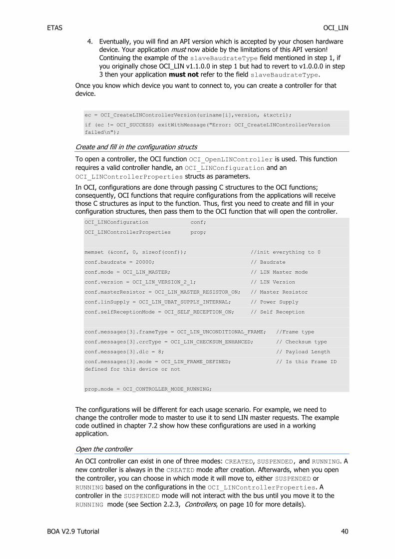
ETAS OCI_LIN
BOA V2.9 Tutorial 40
4. Eventually, you will find an API version which is accepted by your chosen hardware
device. Your application must now abide by the limitations of this API version!
Continuing the example of the slaveBaudrateType field mentioned in step 1, if
you originally chose OCI_LIN v1.1.0.0 in step 1 but had to revert to v1.0.0.0 in step
3 then your application must not refer to the field slaveBaudrateType.
Once you know which device you want to connect to, you can create a controller for that
device.
ec = OCI_CreateLINControllerVersion(uriname[i],version, &txctrl);
if (ec != OCI_SUCCESS) exitWithMessage("Error: OCI_CreateLINControllerVersion
failed\n");
Create and fill in the configuration structs
To open a controller, the OCI function OCI_OpenLINController is used. This function
requires a valid controller handle, an OCI_LINConfiguration and an
OCI_LINControllerProperties structs as parameters.
In OCI, configurations are done through passing C structures to the OCI functions;
consequently, OCI functions that require configurations from the applications will receive
those C structures as input to the function. Thus, first you need to create and fill in your configuration structures, then pass them to the OCI function that will open the controller.
OCI_LINConfiguration conf;
OCI_LINControllerProperties prop;
memset (&conf, 0, sizeof(conf)); //init everything to 0
conf.baudrate = 20000; // Baudrate
conf.mode = OCI_LIN_MASTER; // LIN Master mode
conf.version = OCI_LIN_VERSION_2_1; // LIN Version
conf.masterResistor = OCI_LIN_MASTER_RESISTOR_ON; // Master Resistor
conf.linSupply = OCI_LIN_UBAT_SUPPLY_INTERNAL; // Power Supply
conf.selfReceptionMode = OCI_SELF_RECEPTION_ON; // Self Reception
conf.messages[3].frameType = OCI_LIN_UNCONDITIONAL_FRAME; //Frame type
conf.messages[3].crcType = OCI_LIN_CHECKSUM_ENHANCED; // Checksum type
conf.messages[3].dlc = 8; // Payload Length
conf.messages[3].mode = OCI_LIN_FRAME_DEFINED; // Is this Frame ID
defined for this device or not
prop.mode = OCI_CONTROLLER_MODE_RUNNING;
The configurations will be different for each usage scenario. For example, we need to change the controller mode to master to use it to send LIN master requests. The example
code outlined in chapter 7.2 show how these configurations are used in a working application.
Open the controller
An OCI controller can exist in one of three modes: CREATED, SUSPENDED, and RUNNING. A
new controller is always in the CREATED mode after creation. Afterwards, when you open
the controller, you can choose in which mode it will move to, either SUSPENDED or
RUNNING based on the configurations in the OCI_LINControllerProperties. A
controller in the SUSPENDED mode will not interact with the bus until you move it to the
RUNNING mode (see Section 2.2.3, Controllers, on page 10 for more details).

ETAS OCI_LIN
BOA V2.9 Tutorial 41
The configuration structs for each use case are shown below. The only step left is to pass
the required struct to the function that will open and configure the controller.
ec = OCI_OpenLINController (txctrl, &conf, &prop);
if (ec != OCI_SUCCESS) exitWithMessage("Error: OCI_OpenLINController failed\n");
Now you have a controller that is open and configured. The controller is now nearly ready to
send and receive data. Nevertheless, before you can do that, you need to setup transmit and receive queues respectively. This is done through the functions
OCI_CreateCANTxQueue and OCI_CreateCANRxQueue.
LIN Master
A LIN master is a LIN node that can send LIN master requests. One of the roles of the
master is also to provide the LIN pull up resistor. Those two things have to be specified in the controller configurations as follows
OCI_LINControllerProperties prop;
prop.mode = OCI_CONTROLLER_MODE_RUNNING;
OCI_LINConfiguration conf;
memset (&conf, 0, sizeof(conf)); //init everything to 0
conf.baudrate = 20000; // Baudrate
conf.mode = OCI_LIN_MASTER; // LIN Master mode
conf.version = OCI_LIN_VERSION_2_1; // LIN Version
conf.masterResistor = OCI_LIN_MASTER_RESISTOR_ON; // Master Resistor
conf.linSupply = OCI_LIN_UBAT_SUPPLY_INTERNAL; // Power Supply
conf.selfReceptionMode = OCI_SELF_RECEPTION_ON; // Self Reception
To be able to send LIN master requests, the corresponding frame ID has to be configured as
well
conf.messages[3].frameType = OCI_LIN_UNCONDITIONAL_FRAME; //Frame type
conf.messages[3].crcType = OCI_LIN_CHECKSUM_ENHANCED; // Checksum type
conf.messages[3].dlc = 8; // Payload Length
conf.messages[3].mode = OCI_LIN_FRAME_DEFINED; // Is this Frame ID
defined for this device or not
After this is done in the configuration, and after the controller is opened successfully, you
need to setup a LIN master queue. This queue is able to send LIN master request messages. Each transmit queue transmits LIN master requests with exactly one frame ID; thus, you
need to create a new transmit queue for each frame ID you would like to send master requests for. The code below shows how this could be done.
OCI_QueueHandle txqueue; // Receive Queue handle
OCI_LINTxQueueConfiguration txq_conf; // Receive Queue configurations
txq_conf.type = OCI_LIN_MASTER_QUEUE; // Queue type
txq_conf.frameID = 0x3; // frameID for messages going through this queue
txq_conf.assignedEventFrameID0to31 = 0x0;
txq_conf.assignedEventFrameID32to59 = 0x0;
ec = OCI_CreateLINTxQueue (txctrl, &txq_conf, &txqueue);

ETAS OCI_LIN
BOA V2.9 Tutorial 42
if (ec != OCI_SUCCESS) exitWithMessage("Error: OCI_CreateLINRxQueue failed\n");
After the transmit queue is ready, the remaining task is as simple as creating a LIN master
request message and writing it to that queue.
OCI_LINMessage msg;
msg.type = OCI_LIN_REQUEST;
msg.data.masterRequestMessage.frameID = 0x3;
ec = OCI_WriteLINData(txqueue, OCI_NO_TIME, &msg, 1, NULL);
if (ec != OCI_SUCCESS) exitWithMessage ("Error: OCI_WriteLINData failed\n");
Usually, a LIN master would have a schedule that it would follow to periodically send master requests. This is now merely a programming task that we chose not to include here for
simplicity.
7.1.2 LIN Slave
A LIN master is a LIN node that sends LIN frame bodies. The slave should not pull up the
bus since this is the role of the bus master. This is specified in the configurations as follows
OCI_LINControllerProperties prop;
prop.mode = OCI_CONTROLLER_MODE_RUNNING;
OCI_LINConfiguration conf;
memset (&conf, 0, sizeof(conf)); //init everything to 0
conf.baudrate = 20000; // Baudrate
conf.mode = OCI_LIN_SLAVE; // LIN Slave mode
conf.version = OCI_LIN_VERSION_2_1; // LIN Version
conf.masterResistor = OCI_LIN_MASTER_RESISTOR_OFF; // Master Resistor is off
conf.linSupply = OCI_LIN_UBAT_SUPPLY_INTERNAL; // Power Supply
conf.selfReceptionMode = OCI_SELF_RECEPTION_ON; // Self Reception
To be able to send LIN frame bodies, the corresponding frame ID has to be configured as well
conf.messages[3].frameType = OCI_LIN_UNCONDITIONAL_FRAME; //Frame type
conf.messages[3].crcType = OCI_LIN_CHECKSUM_ENHANCED; // Checksum type
conf.messages[3].dlc = 8; // Payload Length
conf.messages[3].mode = OCI_LIN_FRAME_DEFINED; // Is this Frame ID
defined for this device or not
After this is done in the configuration, and the controller is opened successfully, you need to setup a LIN transmit queue, which is able to send LIN frame bodies. Each transmit queue
transmits LIN frame bodies corresponding to exactly one frame ID; thus, you need to create a new transmit queue for each frame ID you would like to transmit bodies for. The code
below shows how this could be done.
OCI_QueueHandle txqueue; // Receive Queue handle
OCI_LINTxQueueConfiguration txq_conf; // Receive Queue configurations
txq_conf.type = OCI_LIN_FRAME_QUEUE; // Queue type
xq_conf.frameID = 0x3; // frameID for messages going through this queue
txq_conf.assignedEventFrameID0to31 = 0x0;
txq_conf.assignedEventFrameID32to59 = 0x0;

ETAS OCI_LIN
BOA V2.9 Tutorial 43
ec = OCI_CreateLINTxQueue (txctrl, &txq_conf, &txqueue);
if (ec != OCI_SUCCESS) exitWithMessage("Error: OCI_CreateLINRxQueue failed\n");
After the transmit queue is ready, the remaining task is as simple as creating LIN transmit
messages and writing them to that queue. LIN frame queues are not real queues; instead,
they are a buffer than can hold only one message. When a message is added to the queue, this message is placed in that buffer overwriting the previous message that was in its place,
independent of whether the first message was sent on the bus or not. When a LIN slave receives a master request for a frame that it should supply the body for, the slave will simply
send the message that was in the corresponding buffer at the time of reception of the
master request. This special behavior of the LIN transmit queues was designed in BOA to be compatible with the LIN bus specifications.
OCI_LINMessage msg;
char *payload[] = “Hello !”;
msg.type = OCI_LIN_TX_MESSAGE;
msg.data.txMessage.flags = 0;
memcpy(msg.data.txMessage.data, payload, 8);
ec = OCI_WriteLINData(txqueue, OCI_NO_TIME, &msg, 1, NULL);
if (ec != OCI_SUCCESS) exitWithMessage ("Error: OCI_WriteLINData failed\n");
7.1.3 LIN Monitoring
A node that monitors a LIN bus is theoretically a LIN slave node, i.e. a node that is not
allowed to send LIN master requests. But monitoring a LIN bus using BOA is substantially different from functioning as a slave which sends frame bodies. A LIN monitoring node,
need not setup transmit queues; instead, it needs receive queues in order to receive LIN
frames whose heads (master request) are sent by the master and bodies are sent by another slave. The code below shows the configurations needed, note that it is identical to
the slave configurations; you will not see any difference until the setup of the queues.
OCI_LINControllerProperties prop;
prop.mode = OCI_CONTROLLER_MODE_RUNNING;
OCI_LINConfiguration conf;
memset (&conf, 0, sizeof(conf)); //init everything to 0
conf.baudrate = 20000; // Baudrate
conf.mode = OCI_LIN_SLAVE; // LIN Slave mode
conf.version = OCI_LIN_VERSION_2_1; // LIN Version
conf.masterResistor = OCI_LIN_MASTER_RESISTOR_OFF; // Master Resistor is off
conf.linSupply = OCI_LIN_UBAT_SUPPLY_INTERNAL; // Power Supply
conf.selfReceptionMode = OCI_SELF_RECEPTION_ON; // Self Reception
To be able to receive LIN frames, the corresponding frame ID has to be configured as well
conf.messages[3].frameType = OCI_LIN_UNCONDITIONAL_FRAME; //Frame type
conf.messages[3].crcType = OCI_LIN_CHECKSUM_ENHANCED; // Checksum type
conf.messages[3].dlc = 8; // Payload Length
conf.messages[3].mode = OCI_LIN_FRAME_DEFINED; // Is this Frame ID
defined for this device or not

ETAS OCI_LIN
BOA V2.9 Tutorial 44
After this is done in the configuration, and the controller is opened successfully, you need to
setup a LIN receive queue, which is able to receive LIN Rx messages.
OCI_QueueHandle rxqueue; // Receive Queue handle
OCI_LINRxQueueConfiguration rxq_conf; // Receive Queue configurations
rxq_conf.onFrame.function = RxFrameCallback;
rxq_conf.onFrame.userData = NULL;
rxq_conf.onEvent.function = RxEventCallback;
rxq_conf.onEvent.userData = NULL;
rxq_conf.selfReceptionMode = OCI_SELF_RECEPTION_ON;
ec = OCI_CreateLINRxQueue (rxctrl, &rxq_conf, &rxqueue);
if (ec != OCI_SUCCESS) exitWithMessage("Error: OCI_CreateLINRxQueue failed\n");
Like other BOA receive queues, you need to assign callbacks to be called upon the reception
of frames or events to LIN receive queues as well. This is specified in the configurations above. In addition, you need to specify a filter because BOA drops all messages unless they
match some filter. Below, you can find how to create a filter and add it to the receive queue.
OCI_LINRxFilter filter[1];
filter[0].frameIDMask = 0;
filter[0].frameIDValue = 0;
filter[0].tag = 0;
ec = OCI_AddLINFrameFilter(rxqueue, filter, 1);
if (ec != OCI_SUCCESS) exitWithMessage("Error: OCI_AddCANFrameFilter failed\n");
The next code excerpt represents a sample implementation of the callback functions
// Callback for received frames
static void RxFrameCallback (void *userData, struct OCI_LINMessage* msg)
//the receiver frame callback function
{
printf("Message Received\n");
if(msg->type == OCI_LIN_RX_MESSAGE)
{
int i=0;
printf("frameID: 0x%x\n", msg->data.rxMessage.frameID);
while (i< msg->data.rxMessage.dlc)
{
printf("%x ", msg->data.rxMessage.data[i]);
i++;
}
printf("\n");
}
}
// Callback for received events
static void RxEventCallback (void *userData, struct OCI_LINMessage* msg)
// Receiver event callback function
{
exitWithMessage ("Unexpected event received\n");
}

ETAS OCI_LIN
BOA V2.9 Tutorial 45
7.2 Working example: HelloLIN_OCI
A complete, ready-to-run example is included in the installation directory at
Examples\EBI-IP_Examples.zip\HelloLIN_OCI\HelloLIN_OCI.sln. The example
is split into three projects (Master, Slave and Receive) covering all of the topics discussed in
this section, and will allow you to quickly build a working application that uses the OCI interface with LIN hardware.
7.2.1 Operation
To use the example, open the solution in Visual Studio, then build and run one of the
projects.
Where possible, the examples follow the same basic format and use a similar style to the
code that has been shown throughout this tutorial.
Both projects start by searching for attached hardware. Any OCDs present in the default
OCDs folder will be enumerated. Choose an OCD by typing its number and pressing enter.
A controller will be created using the URI of the OCD selected, and then opened.
A queue (Tx or Rx depending on which project was chosen) will then be created on this controller. If a receive queue was created, a white filter will be added to it to allow all
incoming messages to be received.
The program will then operate on the queue in a typical way, demonstrating how to use it.
If the example uses a transmit queue, it will write data to the bus. If a receive queue is used, it will wait for messages from the bus. Press enter to halt transmission/reception.
The controller (and its associated queue) will then be destroyed, and the program will exit.
If the OCD returns an error at any point, the program will exit with an error message.

ETAS ETAS Contact Addresses
BOA V2.9 Tutorial 46
8 ETAS Contact Addresses
ETAS HQ
ETAS GmbH
Borsigstraße 14 Phone: +49 711 89661-0
70469 Stuttgart Fax: +49 711 89661-106
Germany WWW: www.etas.com
ETAS Subsidiaries and Technical Support
For details of your local sales office as well as your local technical support team and product
hotlines, take a look at the ETAS website:
ETAS subsidiaries WWW: www.etas.com/en/contact.php
ETAS technical support WWW: www.etas.com/en/hotlines.php

ETAS Appendix A – BOA Demo
BOA V2.9 Tutorial 47
9 Appendix A – BOA Demo
9.1 Description
Also included in the Examples.zip file is code for the BOA Demo Application, a demonstration
application that has such uses as:
Example of a more complex application that uses BOA OCI
Testing configurations and settings for BOA compatible hardware
Sending or receiving test traffic to / from the HelloXxx_OCI applications given in this document
Sending or receiving data to / from a device on the bus
Being a framework on which you can develop your own code
The application is a suite of three programs, one to support each of the network protocols
CAN, FlexRay and LIN.
Each program gives a menu driven set of actions which provide commands for finding controllers, configuring them, transmitting and receiving messages and interrogating their
state. You are encouraged to modify the program to include more functionality as you need.
For example, you can easily modify this code to add your own configurations to experiment with BOA and OCD behaviour.
9.2 Location
The BOA Demo Application code is included in the EBI-IP_Examples.zip file. This file is located in the BOA EBI-IP Development Kit V2 folder, which is accessible from the ETAS
group under the Windows Start button.
Extract the folder ‘BOA Demo’ to your hard disk. You will need Microsoft Visual Studio 2015 C++ or later to access the solution file.
9.3 Use case examples
9.3.1 Example of a more complex application that uses BOA OCI
The HelloXxx_OCI applications discussed in the main part of the tutorial document are
excellent starting points in learning about the BOA API, but their usefulness is quite limited. This application is an example of a small system that uses the BOA OCI API to control
devices and perform useful functions.
9.3.2 Testing configurations and settings for BOA compatible hardware
If you have a piece of hardware you are not yet familiar with, or if you are developing a new
piece of hardware, this application should be useful in exercising it. It is very easy to change what configuration is used with the hardware so this application is good for experimenting
with the behaviour of different controller configurations, queue configurations and filters.
9.3.3 Sending or receiving data to / from a device on the bus
The BOA Demo Application can be used with a device on a bus to communicate with other devices on the bus that are not under its control.
For example if you use one of the HelloXxx_OCI applications to attach to a device on a bus
then you can use this code to attach to another device on the bus and to communicate with
the HelloXxx_OCI application.
ETAS Appendix A – BOA Demo
BOA V2.9 Tutorial 48
9.3.4 A framework on which you can develop your own code
You may wish to use the BOA Demo Application as a starting point for developing your own
code. Functions in the helpers.c file such as printControllers() and
findControllers() are intended to be useful beyond the scope of BOA Demo.
9.4 How to use the user interface
Each of the 3 programs in the application present you with a menu, there are minor
differences for each protocol. For CAN the menu is
0. Find controllers - this option searches for devices attached to the PC and gives a list of everything it finds. It must be run before a transmitter or receiver can be chosen. If you
connect a new device to the PC after finding controllers then you must run this option again before the new controller will be recognised by the BOA Demo Application.
1. Transmitter - this option gives you the list of found controllers to select a transmitter
from. Once you have chosen you are given a menu of possible configurations to use for the transmitter. After the transmitter is set up, your choices are displayed as part of this
menu item.
2. Receiver - this option gives you the list of found controllers to select a receiver from.
Once you have chosen you are given a menu of possible configurations to use for the receiver. The receiver is configured to display on details of any messages that it
receives. After the receiver is set up, your choices are displayed as part of this menu item.
3. Start transmitting. This option sends a number of unique messages and reports whether
the transmission was successful. If you also have a receiver configured that the receiver will display details of the received messages.
4. Display information about configured controllers. This option displays all retrievable
information about the configuration of any controllers that have been configured using options (1) and (2).
5. Destroy controllers. Resets everything, including the list of found controllers, so you can
start again.
6. Help. A brief description of what to do.
q. Quit. Reset all devices that had been configured and quit the program.
The program that supports LIN has one extra menu option – for configuring a Master controller. This controller may be configured on the same port as either the transmit or the
receive controller so it is possible to transmit and receive LIN messages with only 2 ports.
9.5 How to change configurations and notes on the code
Controller configurations are held in the global array gSettingsOptions[]. This is
initialised in the setXxxConfigs() function in BoaDemoXxxHelpers.c (where ‘Xxx’ is
Can, Lin or Flx). You can edit this function to create a new selection of configurations from which you can choose individual configurations at runtime. If you change the number of
configuration instances then you must also update the size of the array defined in the main
program file.
For FlexRay and LIN the transmit queue configurations are also set as part of the
gSettingsOptions[] array. CAN does not have a configurable transmit queue so there is
no section for this in the CAN gSettingsOptions[] array.
Receive queue configurations and filter settings are coded within the function that sets them
up, setRXController().
Notice that the receiver callback function, rxCallback(), has a switch statement to
handle every type of message that it is capable of receiving so it is easy to add functionality
to extend the scope of its message handling into new areas.

ETAS Appendix A – BOA Demo
BOA V2.9 Tutorial 49
The code is comprehensively documented with comments. These are intended to augment
this tutorial and to help with modifying the code to meet your own aims.