Bnsf Grade Separation
64
Transcript of Bnsf Grade Separation
GUIDELINES FOR RAILROAD GRADE SEPARATION PROJECTS, January 24, 2007
1
TABLE OF CONTENTS
Section / Article Page
1. INTRODUCTION1.1 Purpose . . . . . . . . . . . . . . . . 61.2 Definitions . . . . . . . . . . . . . . . . 61.3 Guidelines and References . . . . . . . . . . . . 7
2. AGREEMENTS2.1 Applicant and Contractor Responsibility . . . . . . . . . 92.2 Railroad Right-of-Way . . . . . . . . . . . . . 92.3 Railroad Right-of-Entry Agreement . . . . . . . . . . 92.4 C & M Agreement . . . . . . . . . . . . . . 92.5 Railroad Review of Submittals and Construction Observation . . . . 10
3. SUBMITTALS3.1 Railroad Review Process . . . . . . . . . . . . 113.2 Contractor Review . . . . . . . . . . . . . . 113.3 Applicant and/or Engineer-of-Record Review . . . . . . . . 113.4 Submittal Schedule . . . . . . . . . . . . . . 113.4.1 Design Submittals . . . . . . . . . . . . . . 113.4.2 Design Calculations . . . . . . . . . . . . . . 113.4.3 Geotechnical Report . . . . . . . . . . . . . 123.4.4 Drainage Report. . . . . . . . . . . . . . 123.4.5 Units . . . . . . . . . . . . . . . . . 123.5 Construction Submittals . . . . . . . . . . . . . 123.6 As Built Submittals . . . . . . . . . . . . . . 16
4. GENERAL REQUIREMENTS FOR GRADE SEPARATION PROJECTS4.1 Railroad Operational Requirements . . . . . . . . . . 174.1.1 Shoofly Track(s). . . . . . . . . . . . . . . 174.1.2 Track Spacing and Shifting . . . . . . . . . . . . 174.1.3 Future Track(s) . . . . . . . . . . . . . . . 174.1.4 Access Road . . . . . . . . . . . . . . 184.2 Grade Separation Structure Type . . . . . . . . . . 184.3 Structure Separation . . . . . . . . . . . . . 184.4 Construction . . . . . . . . . . . . . . . 184.4.1 Construction Clearances . . . . . . . . . . . . 19

GUIDELINES FOR RAILROAD GRADE SEPARATION PROJECTS, January 24, 2007
2
4.4.1.1 Temporary Vertical Construction Clearances . . . . . . . 194.4.1.2 Temporary Horizontal Construction Clearances . . . . . . 194.4.2 Shoring . . . . . . . . . . . . . . . . 194.4.3 Demolition . . . . . . . . . . . . . . . . 194.4.4 Erection . . . . . . . . . . . . . . . . 194.4.5 Falsework . . . . . . . . . . . . . . . . 194.4.6 Vegetation . . . . . . . . . . . . . . . . 194.5 Drainage . . . . . . . . . . . . . . . . 194.5.1 Erosion and Sediment Control . . . . . . . . . . . 204.5.2 Hydraulic Criteria for Bridge and Culvert Openings . . . . . . 204.5.3 Hydraulic Criteria for Drainage Systems Parallel to Railroad Tracks . . 214.6 Fences . . . . . . . . . . . . . . . . . 214.7 Retaining Walls . . . . . . . . . . . . . . . 214.8 Embankment Surcharge. . . . . . . . . . . . . . 224.9 Utilities . . . . . . . . . . . . . . . . . 224.10 Construction Management Team . . . . . . . . . . . 224.11 Railroad Site Observation During Construction . . . . . . . . 23
5. OVERHEAD STRUCTURES5.1 Design . . . . . . . . . . . . . . . . . 255.1.1 Design Plans . . . . . . . . . . . . . . . 255.2 Permanent Clearances . . . . . . . . . . . . . 255.2.1 Permanent Vertical Clearance . . . . . . . . . . . 255.2.2 Permanent Horizontal Clearance . . . . . . . . . . . 265.3 Temporary Clearances . . . . . . . . . . . . . 265.4 Overhead Superstructures . . . . . . . . . . . . 265.4.1 Barrier Rail. . . . . . . . . . . . . . . . 265.4.2 Fence with Barrier Rail . . . . . . . . . . . . . 265.5 Overhead Substructures . . . . . . . . . . . . . 275.5.1 Piers . . . . . . . . . . . . . . . . . 275.5.2 Pier Protection . . . . . . . . . . . . . . . 275.5.3 Abutments . . . . . . . . . . . . . . . . 285.6 Lighting . . . . . . . . . . . . . . . . . 285.7 Drainage and Erosion . . . . . . . . . . . . . 28
6. UNDERPASS STRUCTURES6.1 Design . . . . . . . . . . . . . . . . . 306.1.1 Design Loads . . . . . . . . . . . . . . . 306.1.2 Design Plans and Calculations . . . . . . . . . . . 306.1.3 Concrete Requirements . . . . . . . . . . . . 30
GUIDELINES FOR RAILROAD GRADE SEPARATION PROJECTS, January 24, 2007
3
6.1.4 Reinforcing Steel Requirements . . . . . . . . . . 316.1.5 Prestressing Strand Requirements . . . . . . . . . . 316.1.6 Structural Steel Requirements . . . . . . . . . . . 316.2 Future Track and Access Road . . . . . . . . . . . 326.2.1 Access to Underpass Structure . . . . . . . . . . . 326.3 Skew . . . . . . . . . . . . . . . . . 326.4 Approach Slab . . . . . . . . . . . . . . . 336.5 Structure Separation . . . . . . . . . . . . . . 336.6 Clearances . . . . . . . . . . . . . . . . 336.6.1 Permanent Vertical Clearance . . . . . . . . . . . 336.6.2 Permanent Horizontal Clearance . . . . . . . . . . 346.6.3 Temporary Clearances . . . . . . . . . . . . . 346.7 Sacrificial Beams, Fascia Beams and Impact Protection Devices . . . 346.8 Superstructure . . . . . . . . . . . . . . . 346.8.1 Acceptable Superstructure Types . . . . . . . . . . 346.8.2 Deck Type and Width . . . . . . . . . . . . . 356.8.3 Composite Deck . . . . . . . . . . . . . . 356.8.4 Ballast Retainers, Fences and Handrails . . . . . . . . 356.8.5 Walkway . . . . . . . . . . . . . . . . 356.8.6 Drainage . . . . . . . . . . . . . . . . 356.8.7 Waterproofing . . . . . . . . . . . . . . . 366.8.8 Steel Superstructure . . . . . . . . . . . . . 366.8.8.1 Diaphragms or Cross Frames . . . . . . . . . . . 376.8.8.2 Mechanically-Connected Bottom Flanges . . . . . . . . 376.8.9 Painting of Steel Structures . . . . . . . . . . . 376.8.10 Concrete Superstructure . . . . . . . . . . . . 386.8.10.1 Tie Rods . . . . . . . . . . . . . . . . 386.9 Substructure . . . . . . . . . . . . . . . 386.9.1 Piers . . . . . . . . . . . . . . . . . 386.9.2 Abutments . . . . . . . . . . . . . . . . 396.10 Sequence of Construction . . . . . . . . . . . . 396.11 Construction Excavation . . . . . . . . . . . . 396.12 Temporary Structures . . . . . . . . . . . . . 39
7. TRAILS7.1 At Grade Crossing . . . . . . . . . . . . . . 407.2 Trail Parallel to Track . . . . . . . . . . . . . 407.3 Grade Separated Crossing . . . . . . . . . . . . 407.3.1 Overhead Crossing (Trail over Railroad) . . . . . . . . . 407.3.2 Underpass Crossing (Railroad Structure over Trail) . . . . . . 40
GUIDELINES FOR RAILROAD GRADE SEPARATION PROJECTS, January 24, 2007
4
7.3.2.1 New Underpass Crossing . . . . . . . . . . . 407.3.2.2 Crossing Under Existing Structures. . . . . . . . . . 407.4 Drainage . . . . . . . . . . . . . . . . 417.5 Fence . . . . . . . . . . . . . . . . . 417.6 Signs . . . . . . . . . . . . . . . . . 417.7 Lighting . . . . . . . . . . . . . . . . 41
GUIDELINES FOR RAILROAD GRADE SEPARATION PROJECTS, January 24, 2007
5
APPENDIX Plan # Sheet #General Drawings
General Shoring Requirements . . . . . . . . . . . . . . 710000 1Fence Details . . . . . . . . . . . . . . . . . . . . 711000 1Fence Requirements for Adjacent Trail Outside Railroad Right-of-Way . . 711000 2
Overhead StructuresGeneral Overhead Structure Drawing . . . . . . . . . . . . 711100 1Minimum Layout Requirements for Overhead Structures . . . . . . 711100 2Construction Notes . . . . . . . . . . . . . . . . . . 711100 3Overhead Structure Barriers and Fences . . . . . . . . . . . 711100 4Typical Sections at Abutment Slopes . . . . . . . . . . . . . 711100 5Standards for Pier Protection Walls . . . . . . . . . . . . . 711100 6
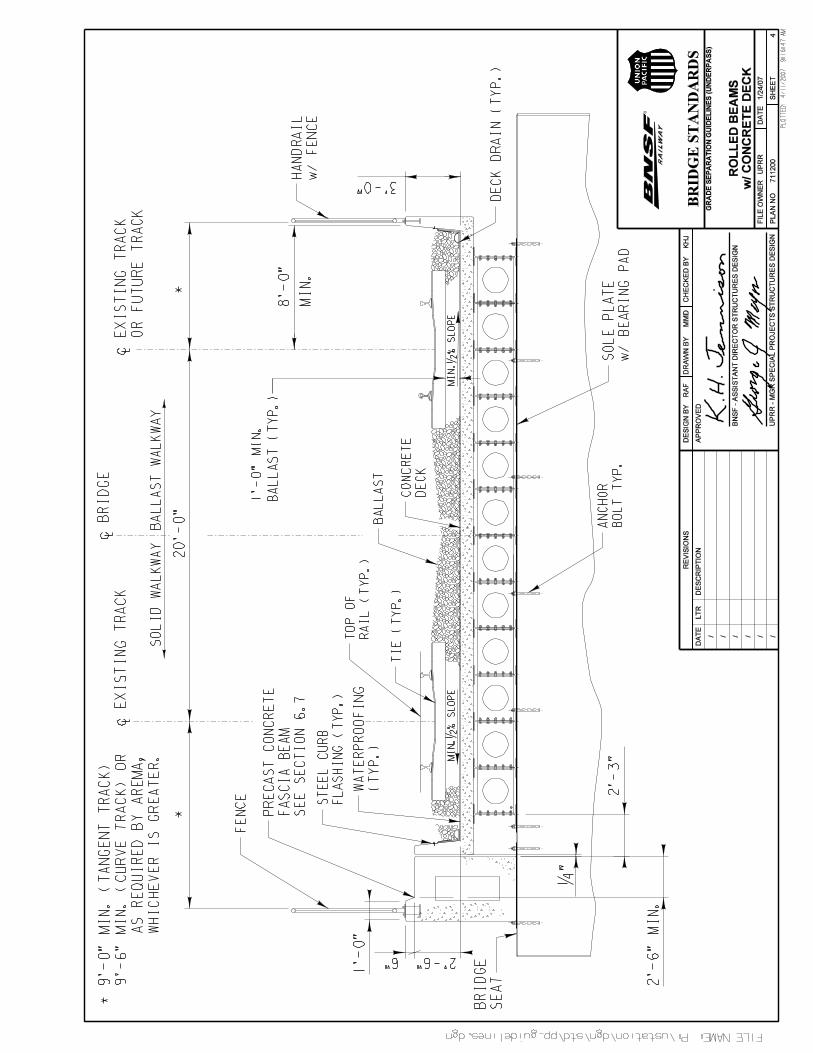
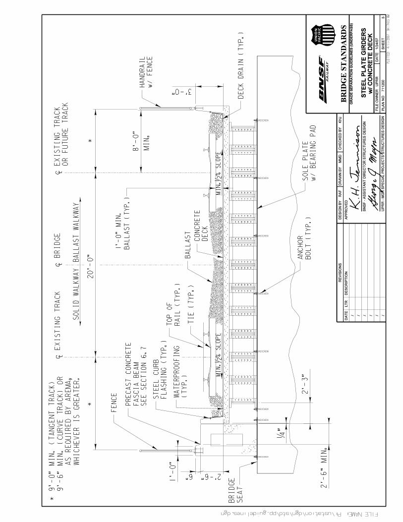
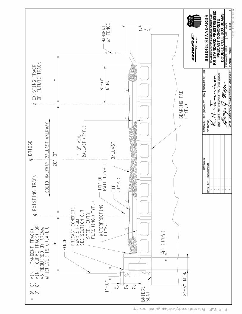
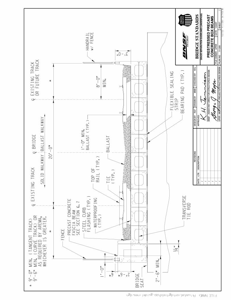
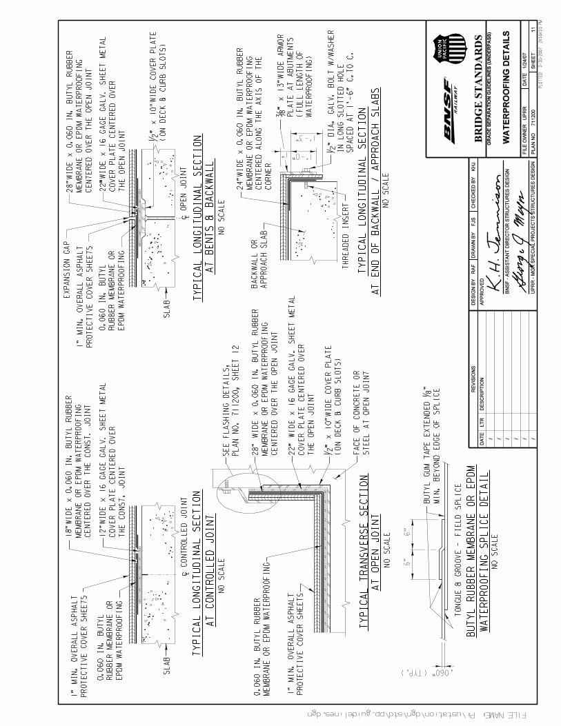
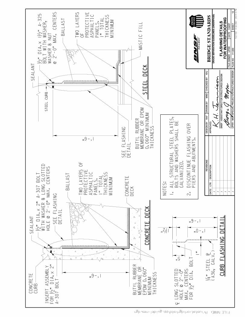
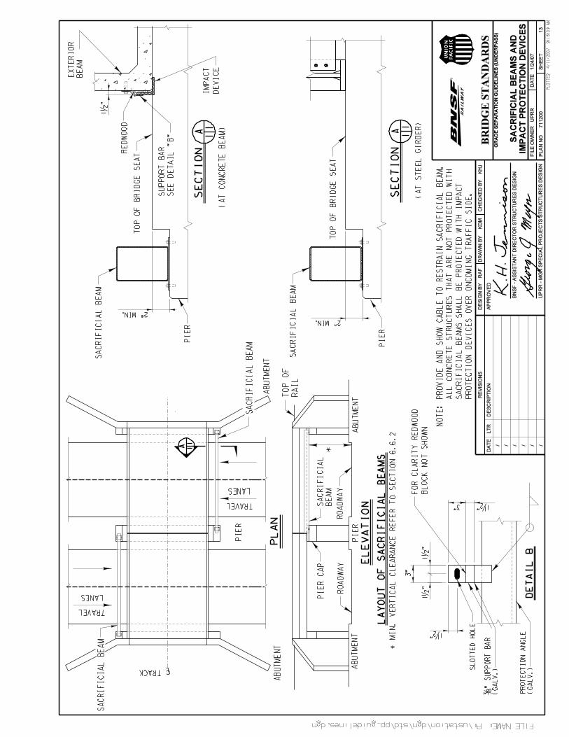
Underpass StructuresMinimum Layout Requirements for Underpass Structures . . . . . . 711200 1Rolled Beams with Steel Plate Deck . . . . . . . . . . . . . 711200 2Steel Plate Girders with Steel Plate Deck . . . . . . . . . . . 711200 3Rolled Beams with Concrete Deck . . . . . . . . . . . . . 711200 4Steel Plate Girders with Concrete Deck . . . . . . . . . . . . 711200 5Railroad Standard Prestressed Precast Concrete Double Cell Box Beams . 711200 6Prestressed Precast Concrete Box Beams . . . . . . . . . . . 711200 7Prestressed Precast Concrete AASHTO Type Beams with Concrete Deck 711200 8Steel Through Plate Girders with Steel Plate Deck . . . . . . . . 711200 9Cast-in-Place Concrete Deck Drain Details . . . . . . . . . . . 711200 10Waterproofing Details . . . . . . . . . . . . . . . . . 711200 11Flashing Details for Waterproofing . . . . . . . . . . . . . 711200 12Sacrificial Beams and Impact Protection Devices . . . . . . . . . 711200 13
GUIDELINES FOR RAILROAD GRADE SEPARATION PROJECTS, January 24, 2007
6
1. INTRODUCTION
1.1 PurposeThe purpose of these Guidelines is to inform Applicants, Contractors and other parties concerned with Railroadpolicies, requirements and standards for the design and construction of Grade Separation Projects. Compliance withthese Guidelines is required to achieve uniformity in the preparation of construction documents for Grade SeparationProjects and to expedite the review and approval by the Railroad of design and construction submittals.
The purpose of review by the Railroad is solely to insure compliance with the minimum standards of the Railroaddealing with particular areas of concern to rail transportation and not to warrant the general safety of the structure.
1.2 DefinitionsAccess Road:
A road used and controlled by the Railroad for maintenance, inspection and repair.Applicant:
Any party proposing a grade separation project on Railroad right-of-way or other Railroad operating location,regardless of track being active or out of service.
AREMA:The current edition of the American Railway Engineering and Maintenance-of-Way Association Manual forRailway Engineering.
AASHTO:The current edition of the American Association of State Highway and Transportation Officials Standard
Specifications for Highway Bridges.C & M Agreement:
A Construction and Maintenance Agreement that has been negotiated between the Railroad and the Applicantthat addresses all the duties and responsibilities of each party regarding the construction of the proposed gradeseparation and the maintenance requirements after construction of the said structure.
Construction Documents:Refers to design plans and calculations, project and/or standard specifications, geotechnical report and drainagereport.
Contractor:The individual, partnership, corporation or joint venture and all principals and representatives (includingApplicant’s subcontractors) with whom the contract is made by the Applicant for the construction of the GradeSeparation Project.
Crossover:A track connection between two adjacent tracks.
Construction Window:A timeframe in which construction or maintenance can be performed by the Contractor with the requiredpresence of a Flagman.
Multiple Main Tracks:Two or more parallel or adjacent main tracks.
Engineer-of-Record:The Professional Engineer that develops the criteria and concept for the project and is responsible for thepreparation of the Plans and Specifications. The Engineer-of-Record shall be registered in the state of the projectlocation. The Engineer-of-Record may be the Applicant’s in-house staff or a consultant retained by the Applicant.The Contractor shall not employ the Engineer-of-Record as the Contractor's Engineer-of-Record or as aSpecialty Engineer, with the exception of design build projects.

GUIDELINES FOR RAILROAD GRADE SEPARATION PROJECTS, January 24, 2007
7
Flagman:A qualified employee of the Railroad providing protection from Railroad operations per Railroad requirements.
Guidelines:Refers to the information contained in this document or referenced in AREMA or AASHTO.
Grade Separation Project:A project that includes an Overhead or Underpass Structure that crosses the Railroad right-of-way or otherRailroad operating location regardless of track status being active or out of service.
Main Track:A track extending through yards and between stations that must not be occupied without proper authority.
Overhead Structure:A Roadway and Trail or pedestrian Structure over the Railroad right-of-way.
Railroad Local Representative:The individual designated by the Railroad as the primary point of contact for the project.
Railroad:Refers to the BNSF and/or Union Pacific Railroad.
Railroad Right-of-Entry Agreement:An agreement between the Railroad and an Applicant or a Contractor allowing access to Railroad property.
Siding:A track connected to the main track and used for meeting, storing or passing trains.
Single Track:A main track where trains operate in both directions.
Timetable:A Railroad publication with instructions on train, engine or equipment movement. It also contains other essentialRailroad information.
Trail:A pathway impacting Railroad right-of-way or other Railroad operating locations regardless of track status beingactive or out of service. This includes pedestrian, bicycle, approved motorized recreational equipment andequestrian uses.
Underpass Structure:A Railroad Structure over a Roadway and/or Trail.
Yard:A system of tracks, other than main tracks and sidings, used for making up trains, storing cars and otherpurposes.
Yard Limits:A portion of main track designated by “yard limit” signs and included in the timetable special instructions or atrack bulletin.
1.3 Guidelines and ReferencesThese Guidelines are provided for reference only and are subject to revision without notice. These Guidelinescannot be taken as authority to construct. Railroad approval of construction documents, execution of a C & MAgreement and Railroad Right-of-Entry Agreement (if applicable) are required prior to beginning construction.
These Guidelines supplement the current (AREMA) Manual for Railway Engineering, AASHTO and State RailroadRegulatory Body requirements. Where these Guidelines and the documents referenced in the preceding sentencediffer, these Guidelines will govern.

GUIDELINES FOR RAILROAD GRADE SEPARATION PROJECTS, January 24, 2007
8
The AREMA Manual is available from:American Railway Engineering and Maintenance-of-Way Association10003 Derekwood Lane Suite 210Lanham, MD 20706 – 4362Phone: (301) 459-3200FAX: (301) 459-8077www.arema.org
The specific Railroad requirements for a Grade Separation Project, as addressed in this document, shall be followedat all locations where the Railroad operates, regardless of track ownership or track status, either active or out ofservice.
Any items affecting Railroad property not covered in these Guidelines shall be subject to the Railroad’s prior reviewand approval.
All new or modified Overhead Structures or Underpass Structures shall be designed in accordance with the mostcurrent policies, requirements and standards of the Railroad. These guidelines do not apply to existing structures.
GUIDELINES FOR RAILROAD GRADE SEPARATION PROJECTS, January 24, 2007
9
2. AGREEMENTS
2.1 Applicant and Contractor ResponsibilityThe Applicant, at its expense, shall be solely responsible for all costs, design, construction, future replacement,maintenance and serviceability of the proposed Grade Separation Project, except as noted otherwise in the C & MAgreement with the Railroad. The Applicant shall develop design plans including, without limitation, all proceduresnecessary to construct and maintain the proposed Grade Separation Project, which cause no interruption to Railroadoperations during and after construction. The Applicant must verify with the Railroad Local Representative for thelatest version of these guidelines prior to developing Construction Documents.
The Applicant shall be responsible for obtaining all Federal, State, local and other permits for construction of theGrade Separation Project.
The Applicant and/or the Engineer-of-Record have the ultimate responsibility and liability for the ConstructionDocuments and liability for damages to Railroad property during and after construction of the project.
The Contractor is responsible to comply with the construction documents prepared by the Applicant. The Contractorshall comply with Railroad requirements stated in the C & M Agreement prior to the commencement of anyconstruction. The Contractor shall develop work plans that ensure the track(s) remain open to train traffic perRailroad requirements as stated in the C & M Agreement and meet the requirements of the Railroad Right-of-EntryAgreement (if applicable).
The Applicant is responsible for the security and safety of all people including the general public and trespassers,and the protection of Railroad infrastructure within the limits of the proposed Grade Separation Project. Any damageto Railroad property such as track, signal equipment or structure could result in a train derailment. All damages mustbe reported immediately to the Railroad Local Representative in charge of the project and to the Railroad Manager ofTrack Maintenance (MTM).
The Applicant and Contractor are required to meet all safety standards as defined by the Railroad, Federal RailroadAdministration (FRA), Division of Occupational Safety and Health Administration (OSHA), Local, State and FederalGovernments and the State Railroad Regulatory Body.
2.2 Railroad Right-of-WayThe Railroad right-of-way accommodates existing tracks, drainage systems, multiple utilities, Access Roads andspace for future track(s). The proposed Grade Separation Project shall not limit current or future Railroad operatingcapacity and utility accommodations within the Railroad right-of-way.
2.3 Railroad Right-of-Entry AgreementThe Applicant, Contractor or their representatives must sign the Railroad’s Contractor’s Right-of-Entry Agreement (ifapplicable) and/or obtain a valid Right-of-Entry permit from the Railroad and comply with all Railroad requirementswhen working within the Railroad right-of-way limits. Limits of Railroad right-of-way are to be located by theApplicant and identified on the plans.
2.4 C & M AgreementAny Overhead Structure or Underpass Structure impacting the Railroad will require the Applicant to execute a C & MAgreement prior to any construction on Railroad right-of-way. The C & M Agreement cannot be signed without theRailroad’s prior approval of construction documents. The C & M agreement shall include a funding source, cost
GUIDELINES FOR RAILROAD GRADE SEPARATION PROJECTS, January 24, 2007
10
estimate, insurance and indemnification requirements, method of payment, responsibility for design, construction,ownership, maintenance and future replacement.
The Applicant shall own, maintain and replace the proposed Overhead Structure or Underpass Structure at no costto the Railroad and with no interruption to Railroad operations during construction, maintenance and futurereplacement of the Structure. The Railroad shall, at its own expense, be responsible for ownership and maintenanceof track components only.
The Applicant is responsible for performing the work in accordance with the terms specified in the C & M Agreement.This responsibility includes, without limitation, compliance with all Railroad requirements, Federal, State and LocalLaws and applicable county or municipal ordinances and regulations.
2.5 Railroad Review of Submittals and Construction ObservationThe Applicant will be responsible for all costs associated with the Railroad or its consultant’s review of design andconstruction documents. Prior to any review, the Railroad Local Representative shall receive written notice from theApplicant agreeing to pay all costs associated with review of the submittals and project site observations duringdesign and construction phases of the project. Review expenses shall include all costs for in-house personnel and/orconsultants retained by the Railroad. The estimated costs shall not be the upper limit of the costs but will provide aguideline for budgeting purposes. Review cost is a function of the quality of submittals received from the Applicant.Regardless, all actual costs incurred by the Railroad or its consultant during the plan review process and constructionmonitoring phase of the work shall be fully recoverable from the Applicant.
GUIDELINES FOR RAILROAD GRADE SEPARATION PROJECTS, January 24, 2007
11
3. SUBMITTALS
3.1 Railroad Review ProcessAll design and construction submittals shall be transmitted to the Railroad Local Representative. The submittal willthen be forwarded to the Railroad’s Central Engineering department. The Central Engineering department shall havethe option of reviewing the project documents in-house or by using an outside consultant. If an outside consultant isused to review the design documents, the Central Engineering department representative will arrange forcommunication with the Applicant to resolve design issues. During the review process, the Railroad LocalRepresentative shall be the point of contact for resolving outstanding issues.
It should be noted that the Railroad’s review and approval of construction documents does not relieve the Applicantand/or Engineer-of-Record from the ultimate responsibility and liability for damages to Railroad property during andafter construction of the proposed Grade Separation Project, nor does it relieve the Applicant and the Contractor fromtheir responsibilities, obligations and/or liabilities under the C & M Agreement and the Contractor’s Right-of-EntryAgreement (if applicable). Railroad’s approval of construction documents will be given with the understanding thatRailroad makes no representations or warranty as to the validity, accuracy, legal compliance or completeness ofsuch documents and that any reliance by the Applicant, Engineer-of-Record or Contractor on such documents is atthe risk of Applicant, Engineer-of-Record and Contractor.
3.2 Contractor ReviewThe Contractor must review all construction submittals to ensure that the materials and proposed method ofconstruction are compatible with the existing site conditions. The Contractor’s work plan must be developed to allowRailroad traffic to remain in service per Railroad requirements and C&M Agreement.
3.3 Applicant and/or Engineer-of-Record ReviewThe Applicant and/or Engineer-of-Record must review and approve each construction submittal for compliance withthe construction documents, AREMA and/or AASHTO, and these Guidelines before forwarding the submittal to theRailroad for review and approval.
3.4 Submittal ScheduleThe Applicant shall schedule submittals per Tables 3-1 or 3-2 to ensure adequate time for review. The Applicant shallnot expect a lesser time for review than that indicated in the tables nor shall the Railroad be responsible for delayeddesign and construction. Partial, incomplete or inadequate submittals will be rejected, thus delaying the approval.Revised submittals will follow the same procedure as the initial submittal until all issues are resolved. At the 100%submittal, prior to submission to the Railroad, all design plans and calculations, project specifications/SpecialProvisions, the geotechnical report and the drainage report must be signed and stamped by a registered ProfessionalEngineer familiar with the Railroad requirements and licensed in the State where the project is located.
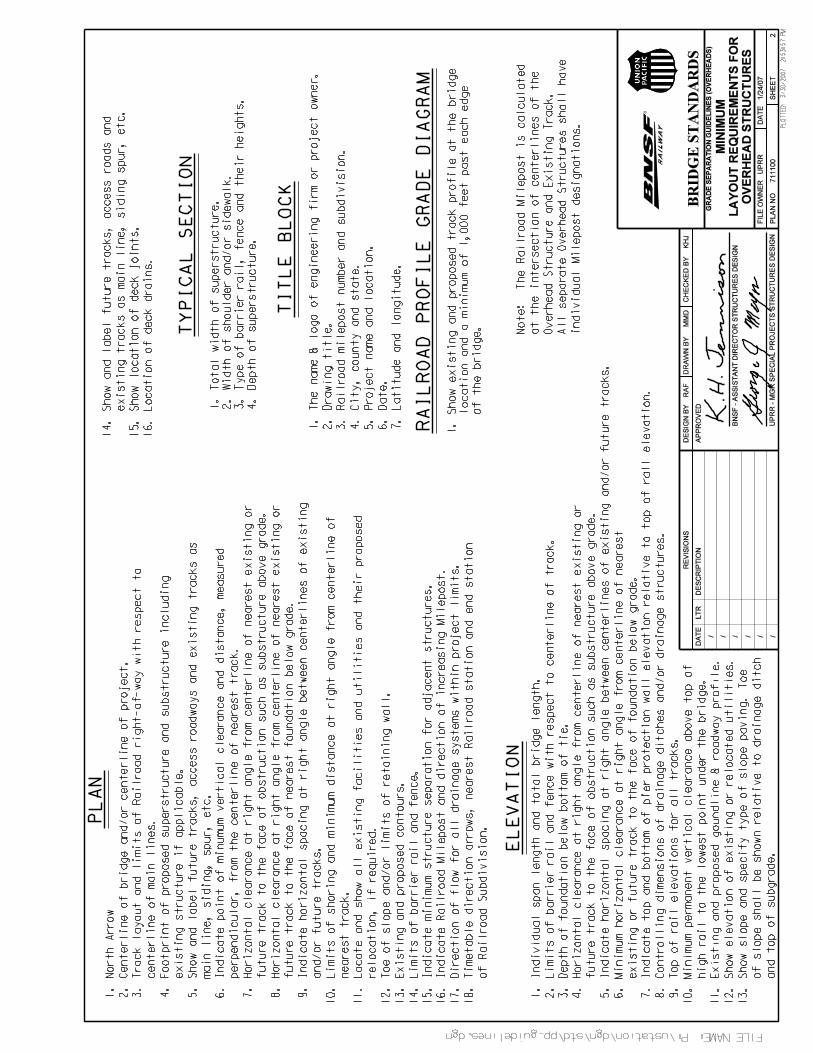
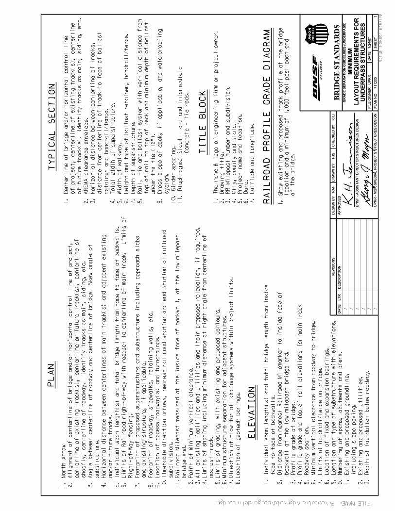
3.4.1 Design SubmittalsThe Applicant or their representative shall submit all applicable design submittals as shown in Table 3-1 or 3-2 to theRailroad for review and approval following their own internal review and approval of the submittal. Design plans shallbe submitted in 11”x17” hard copy format as well as electronic .pdf format. See Plan No. 711100, sheets 2 and 3 andalso Plan No. 711200, sheet 1 for additional information regarding items to be included in the Design Plans.
3.4.2 Design CalculationsDesign calculations shall be provided for all structures, except Overhead Structures, to be constructed as part of theproject. Design Calculations shall be clear, readable and easy to follow. Computer program generated output or

GUIDELINES FOR RAILROAD GRADE SEPARATION PROJECTS, January 24, 2007
12
data sheet calculations shall be accompanied by input data information and sample calculations to verify theaccuracy of the computer output.
3.4.3 Geotechnical ReportA geotechnical report shall be provided covering all bridges and retaining walls. The preliminary geotechnical reportshall include enough information to support foundation design calculations and backfill design requirements. Thefinal geotechnical report shall have recommendations consistent with those used in the final structural design.
3.4.4 Drainage ReportA drainage report is required if the Grade Separation Project necessitates changes in existing drainage patterns orincreases in drainage flow on Railroad right-of-way. See Section 4.5.2 and 4.5.3 for hydraulic criteria to be used.
3.4.5 UnitsAll controlling dimensions, elevations, design criteria, assumptions and material stresses shall be expressed inEnglish units. Dual units with English units in parenthesis are acceptable for projects that require the use of Metricunits per Federal, State and/or Local government requirements.
3.5 Construction SubmittalsThe Applicant or their representative shall submit all applicable construction submittals defined in Tables 3-1 or 3-2 tothe Railroad for review and approval following their own internal review and approval of the submittal. The Engineer-of-Record’s review comments must be submitted to the Railroad along with the construction submittal.
Table 3-1, Overhead Structures
Phase Type of Submittals FormatRailroadReviewTime
Design A Concept (Plans and Site Pictures) 4 hard copiesand .pdf 4 weeks
B30% (Applicant response, Design Plans, Project Specifications,Drainage Report, Shoofly Design, Construction Phasing Plans)
4 hard copiesand .pdf 4 weeks
C100% (Applicant response, Design Plans, ProjectSpecifications, Drainage Report, Shoofly Design, ConstructionPhasing Plans)
4 hard copiesand .pdf 4 weeks
Construction ShoringFalseworkDemolitionErectionErosion ControlConstruction Phasing Plans
4 hard copiesand .pdf 4 weeks
All .pdf files shall be submitted on Compact Disc (CD) and may also be transmitted electronically via e-mail orthrough an internet ftp site
A. The Concept Submittal shall, at a minimum, include the following:
1. Plan, Elevation and Typical Section of proposed grade separation.2. Photo log with pictures of the proposed project location. Site pictures shall be in all controlling
directions including, but not limited to, North, East, South and West. The plan view should show areference location and direction for each picture.
GUIDELINES FOR RAILROAD GRADE SEPARATION PROJECTS, January 24, 2007
13
Four (4) sets of the concept submittal shall be transmitted to the Railroad Local Representative. Allow four(4) weeks for in-house review by the Railroad’s Local Representative and Local Operating Unit from the timethe submittal is received.
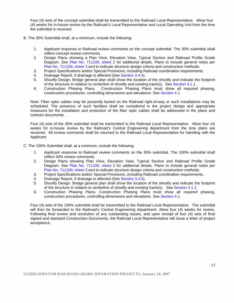
B. The 30% Submittal shall, at a minimum, include the following:
1. Applicant response to Railroad review comments on the concept submittal. The 30% submittal shallreflect concept review comments.
2. Design Plans showing a Plan View, Elevation View, Typical Section and Railroad Profile GradeDiagram. See Plan No. 711100, sheet 2 for additional details. Plans to include general notes perPlan No. 711100, sheet 3 and to indicate structure design criteria and construction methods.
3. Project Specifications and/or Special Provisions, including Railroad coordination requirements.4. Drainage Report, if drainage is affected (See Section 3.4.4).5. Shoofly Design. Bridge general plan shall show the location of the shoofly and indicate the footprint
of the structure in relation to centerline of shoofly and existing track(s). See Section 4.1.1.6. Construction Phasing Plans. Construction Phasing Plans must show all required phasing,
construction procedures, controlling dimensions and elevations. See Section 4.1.
Note: Fiber optic cables may be presently buried on the Railroad right-of-way or such installations may bescheduled. The presence of such facilities shall be considered in the project design and appropriatemeasures for the installation and protection of the fiber optic cables shall be addressed in the plans andcontract documents.
Four (4) sets of the 30% submittal shall be transmitted to the Railroad Local Representative. Allow four (4)weeks for in-house review by the Railroad’s Central Engineering department from the time plans arereceived. All review comments shall be returned to the Railroad Local Representative for handling with theApplicant.
C. The 100% Submittal shall, at a minimum, include the following:
1. Applicant response to Railroad review comments on the 30% submittal. The 100% submittal shallreflect 30% review comments.
2. Design Plans showing Plan View, Elevation View, Typical Section and Railroad Profile GradeDiagram. See Plan No. 711100, sheet 2 for additional details. Plans to include general notes perPlan No. 711100, sheet 3 and to indicate structure design criteria and construction methods.
3. Project Specifications and/or Special Provisions, including Railroad coordination requirements.4. Drainage Report, if drainage is affected (See Section 3.4.4).5. Shoofly Design. Bridge general plan shall show the location of the shoofly and indicate the footprint
of the structure in relation to centerline of shoofly and existing track(s). See Section 4.1.1.6. Construction Phasing Plans. Construction Phasing Plans must show all required phasing,
construction procedures, controlling dimensions and elevations. See Section 4.1.
Four (4) sets of the 100% submittal shall be transmitted to the Railroad Local Representative. The submittalwill then be forwarded to the Railroad’s Central Engineering department. Allow four (4) weeks for review.Following final review and resolution of any outstanding issues, and upon receipt of four (4) sets of finalsigned and stamped Construction Documents, the Railroad Local Representative will issue a letter of projectacceptance.
GUIDELINES FOR RAILROAD GRADE SEPARATION PROJECTS, January 24, 2007
14
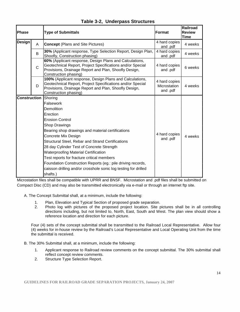
Table 3-2, Underpass Structures
Phase Type of Submittals FormatRailroadReviewTime
Design A Concept (Plans and Site Pictures) 4 hard copiesand .pdf 4 weeks
B 30% (Applicant response, Type Selection Report, Design Plan,Shoofly, Construction phasing)
4 hard copiesand .pdf 4 weeks
C
60% (Applicant response, Design Plans and Calculations,Geotechnical Report, Project Specifications and/or SpecialProvisions, Drainage Report and Plan, Shoofly Design,Construction phasing)
4 hard copiesand .pdf 6 weeks
D
100% (Applicant response, Design Plans and Calculations,Geotechnical Report, Project Specifications and/or SpecialProvisions, Drainage Report and Plan, Shoofly Design,Construction phasing)
4 hard copiesMicrostation
and .pdf4 weeks
Construction ShoringFalseworkDemolitionErectionErosion ControlShop DrawingsBearing shop drawings and material certificationsConcrete Mix DesignStructural Steel, Rebar and Strand Certifications28 day Cylinder Test of Concrete StrengthWaterproofing Material CertificationTest reports for fracture critical membersFoundation Construction Reports (eg.: pile driving records,caisson drilling and/or crosshole sonic log testing for drilledshafts.)
4 hard copiesand .pdf 4 weeks
Microstation files shall be compatible with UPRR and BNSF. Microstation and .pdf files shall be submitted onCompact Disc (CD) and may also be transmitted electronically via e-mail or through an internet ftp site.
A. The Concept Submittal shall, at a minimum, include the following:
1. Plan, Elevation and Typical Section of proposed grade separation.2. Photo log with pictures of the proposed project location. Site pictures shall be in all controlling
directions including, but not limited to, North, East, South and West. The plan view should show areference location and direction for each picture.
Four (4) sets of the concept submittal shall be transmitted to the Railroad Local Representative. Allow four(4) weeks for in-house review by the Railroad’s Local Representative and Local Operating Unit from the timethe submittal is received.
B. The 30% Submittal shall, at a minimum, include the following:
1. Applicant response to Railroad review comments on the concept submittal. The 30% submittal shallreflect concept review comments.
2. Structure Type Selection Report.
GUIDELINES FOR RAILROAD GRADE SEPARATION PROJECTS, January 24, 2007
15
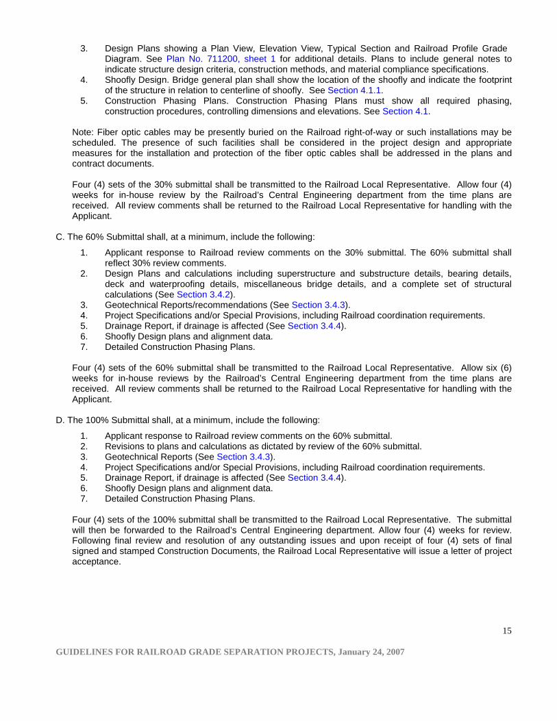
3. Design Plans showing a Plan View, Elevation View, Typical Section and Railroad Profile GradeDiagram. See Plan No. 711200, sheet 1 for additional details. Plans to include general notes toindicate structure design criteria, construction methods, and material compliance specifications.
4. Shoofly Design. Bridge general plan shall show the location of the shoofly and indicate the footprintof the structure in relation to centerline of shoofly. See Section 4.1.1.
5. Construction Phasing Plans. Construction Phasing Plans must show all required phasing,construction procedures, controlling dimensions and elevations. See Section 4.1.
Note: Fiber optic cables may be presently buried on the Railroad right-of-way or such installations may bescheduled. The presence of such facilities shall be considered in the project design and appropriatemeasures for the installation and protection of the fiber optic cables shall be addressed in the plans andcontract documents.
Four (4) sets of the 30% submittal shall be transmitted to the Railroad Local Representative. Allow four (4)weeks for in-house review by the Railroad’s Central Engineering department from the time plans arereceived. All review comments shall be returned to the Railroad Local Representative for handling with theApplicant.
C. The 60% Submittal shall, at a minimum, include the following:
1. Applicant response to Railroad review comments on the 30% submittal. The 60% submittal shallreflect 30% review comments.
2. Design Plans and calculations including superstructure and substructure details, bearing details,deck and waterproofing details, miscellaneous bridge details, and a complete set of structuralcalculations (See Section 3.4.2).
3. Geotechnical Reports/recommendations (See Section 3.4.3).4. Project Specifications and/or Special Provisions, including Railroad coordination requirements.5. Drainage Report, if drainage is affected (See Section 3.4.4).6. Shoofly Design plans and alignment data.7. Detailed Construction Phasing Plans.
Four (4) sets of the 60% submittal shall be transmitted to the Railroad Local Representative. Allow six (6)weeks for in-house reviews by the Railroad’s Central Engineering department from the time plans arereceived. All review comments shall be returned to the Railroad Local Representative for handling with theApplicant.
D. The 100% Submittal shall, at a minimum, include the following:
1. Applicant response to Railroad review comments on the 60% submittal.2. Revisions to plans and calculations as dictated by review of the 60% submittal.3. Geotechnical Reports (See Section 3.4.3).4. Project Specifications and/or Special Provisions, including Railroad coordination requirements.5. Drainage Report, if drainage is affected (See Section 3.4.4).6. Shoofly Design plans and alignment data.7. Detailed Construction Phasing Plans.
Four (4) sets of the 100% submittal shall be transmitted to the Railroad Local Representative. The submittalwill then be forwarded to the Railroad’s Central Engineering department. Allow four (4) weeks for review.Following final review and resolution of any outstanding issues and upon receipt of four (4) sets of finalsigned and stamped Construction Documents, the Railroad Local Representative will issue a letter of projectacceptance.
GUIDELINES FOR RAILROAD GRADE SEPARATION PROJECTS, January 24, 2007
16
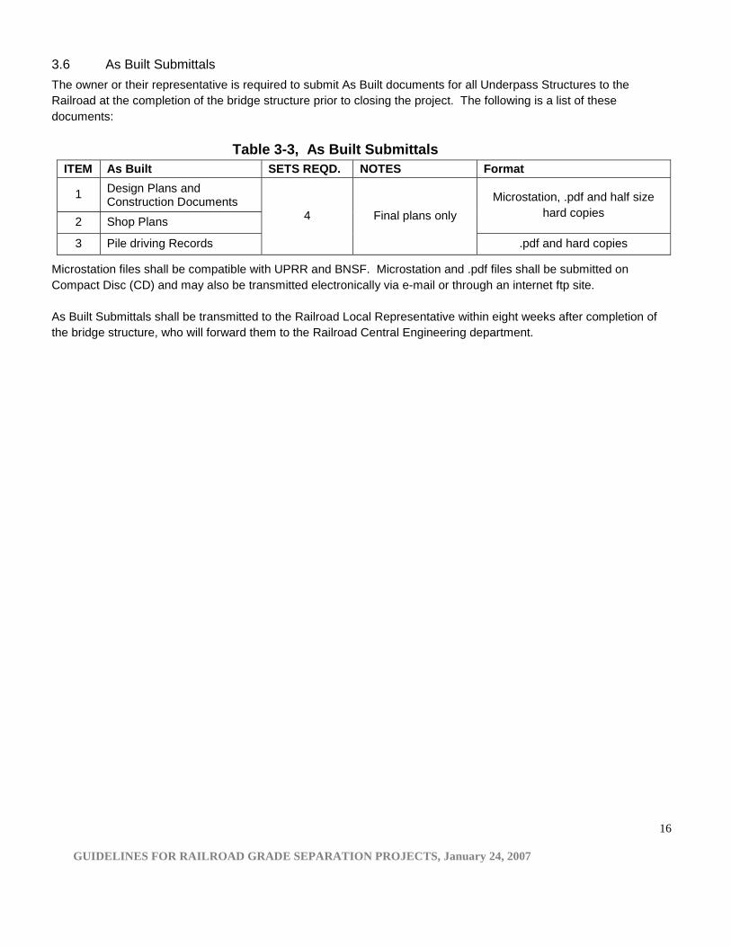
3.6 As Built SubmittalsThe owner or their representative is required to submit As Built documents for all Underpass Structures to theRailroad at the completion of the bridge structure prior to closing the project. The following is a list of thesedocuments:
Table 3-3, As Built SubmittalsITEM As Built SETS REQD. NOTES Format
1 Design Plans andConstruction Documents
2 Shop Plans
Microstation, .pdf and half sizehard copies
3 Pile driving Records
4 Final plans only
.pdf and hard copies
Microstation files shall be compatible with UPRR and BNSF. Microstation and .pdf files shall be submitted onCompact Disc (CD) and may also be transmitted electronically via e-mail or through an internet ftp site.
As Built Submittals shall be transmitted to the Railroad Local Representative within eight weeks after completion ofthe bridge structure, who will forward them to the Railroad Central Engineering department.
GUIDELINES FOR RAILROAD GRADE SEPARATION PROJECTS, January 24, 2007
17
4. GENERAL REQUIREMENTS FOR GRADE SEPARATION PROJECTSThe recommendations provided within this Section are intended for all Grade Separation Projects impacting theRailroad. All Grade Separation Projects shall be designed in accordance with the requirements in this section and thespecific requirements of all applicable sections within these Guidelines.
4.1 Railroad Operational RequirementsIt is essential that the proposed construction be performed without interference to Railroad operations.The most effective method for reducing interference to Railroad operations for construction of Grade SeparationProjects is to use an Overhead Structure and avoid an Underpass Structure. The Railroad recommends the use ofan Overhead Structure, which can be designed and constructed without interruption to Railroad operations. If anUnderpass Structure is required, the project must temporarily reroute train traffic around the construction site byutilizing a shoofly track subject to local operating review and approval. Shoofly track(s) shall be designed per Section4.1.1.
Construction activities that impact Railroad operations must be coordinated with the Railroad. The proposed stagingand phasing must be reviewed and approved by the Railroad at the concept stage and re-reviewed duringdevelopment of detailed plans. Special Provisions must include Railroad coordination to improve Contractorunderstanding of Railroad requirements prior to letting of the proposed Grade Separation project.
Grade separation structures may require an inside guard rail per Railroad standards.
4.1.1 Shoofly Track(s)Shoofly track shall be designed for maximum authorized timetable speed for freight and/or passenger trains, perRailroad track standards and operating requirements. Other restrictions specific to the individual Railroad may apply.Applicant needs to verify this with Railroad’s Central Engineering department. The proposed shoofly must bedesigned to account for track settlement. Construction staging shall be designed to keep the Railroad tracks fullyoperational at all times except for pre-approved construction windows during cut over operations. The Applicantmust schedule track related submittals per Table 3-1 or 3-2 for Railroad review and approval.
4.1.2 Track Spacing and ShiftingExisting track spacing will be maintained unless otherwise required by the Railroad. Future track shifting anddirection of shifting must be verified at the preliminary stage of the feasibility study for the proposed GradeSeparation Project. Due to safety and operational needs, existing track spacing may need to be increased to meetcurrent safety standards. The Railroad requires a minimum spacing of 20 feet between freight tracks and 25 feetbetween freight and commuter tracks.
4.1.3 Future Track(s)A fundamental part of any feasibility study is to verify the need, requirement and location of future main, siding and/or spur tracks. The Railroad has the right to reserve the Railroad right-of-way for future expansion per Section 2.2. Inmany cases the Railroad may have specific plans for additional tracks for all critical, major and other service routes.In other cases a transit agency may have long range plans to use part of or the entire corridor for future transit orcommuter rail service. Should additional tracks be a possibility, they should be included in the design process. Spaceis to be provided for one or more future tracks as required for long range planning or other operating requirements.Where provisions are made for more than two tracks, space is to be provided for an Access Road on both sides ofthe tracks.
GUIDELINES FOR RAILROAD GRADE SEPARATION PROJECTS, January 24, 2007
18
All structures located within critical, major and other service routes that require additional track(s) shall be designedto accommodate future track expansion. Future freight track shall be located a minimum of 20 feet from thecenterline of the nearest existing track. Future commuter track shall be located a minimum of 25 feet from thecenterline of nearest existing or future freight track.
4.1.4 Access RoadAccess Road requirements and location should be verified at the concept stage of the proposed Grade SeparationProject. Access Roads provide maintenance and emergency access to the Railroad local operating units. AccessRoad, Access Road bridge or Access Road turnaround with a minimum of 50’ radius is to be provided as designatedby the local Railroad Operating Department. Grade Separation design should include adequate access to existingRailroad facilities along and/or within its right-of-way.
Minimum Access Road width shall be 10 feet and the centerline of the Access Road shall be located a minimum of20 feet from centerline of nearest existing or future track.
4.2 Grade Separation Structure TypeThe Railroad discourages Underpass Structures due to safety concerns, possible interruption to Railroad operations,cost, and limitation of future replacement and maintenance. In general, the least complicated method for a gradeseparation is to use an Overhead Structure. Economy alone shall not be the governing factor in determining structuretype. The analysis of Cost-Benefit ratio shall be fully considered before the structure type is finalized. Cost-Benefitratio must include all costs associated with interruption to Railroad operations during construction of the proposedstructure and/or future replacement structure in addition to future maintenance and other applicable costs.
4.3 Structure SeparationAll non-freight Railroad structures, with the exception of Access Road structures running adjacent to existing orproposed Railroad structures, shall be outside the Railroad right-of-way limits or as far away as practical. Clearhorizontal separation between structures shall never be less than 25 feet, measured perpendicular from proposedstructure(s) to existing or future Railroad structure(s).
Vertical and horizontal structure separations shall be subject to the Railroad’s existing, proposed or future structuretype, size, location and other site constraints.
4.4 ConstructionRailroad’s review and approval of construction submittals defined in Table 3-1 or 3-2 are required. The Applicant andit’s Contractor are responsible to comply with construction documents approved by the Railroad and must execute awork plan that enables the track(s) to remain open to train traffic per Railroad requirements. The Engineer-of-Recordand the Applicant shall evaluate the quality of materials furnished and work performed by the Contractor. All fieldinspection reports, quality control reports and final As Built plans shall be submitted to the Railroad. The project siteshall be inspected by the Railroad at the Applicant’s expense during construction and toward the end of constructionfor final acceptance before the Contractor demobilizes.
The review of construction submittals and observation of the construction site shall neither relieve the Applicant,Engineer-of-Record nor the Contractor from the ultimate responsibility and liability for the construction on or damagesto Railroad property during and after construction of the project.
GUIDELINES FOR RAILROAD GRADE SEPARATION PROJECTS, January 24, 2007
19
4.4.1 Construction ClearancesTemporary horizontal and vertical construction clearances shall be shown on the plans for all Grade SeparationProjects impacting the Railroad. Every effort must be made to design for greater clearances. Greater clearances maybe required for special cases to satisfy local operating conditions such as required sight distance for signals.Reduced temporary construction clearances, which are less than construction clearances defined in Section 4.4.1.1and 4.4.1.2, will require special review and approval by the Railroad.
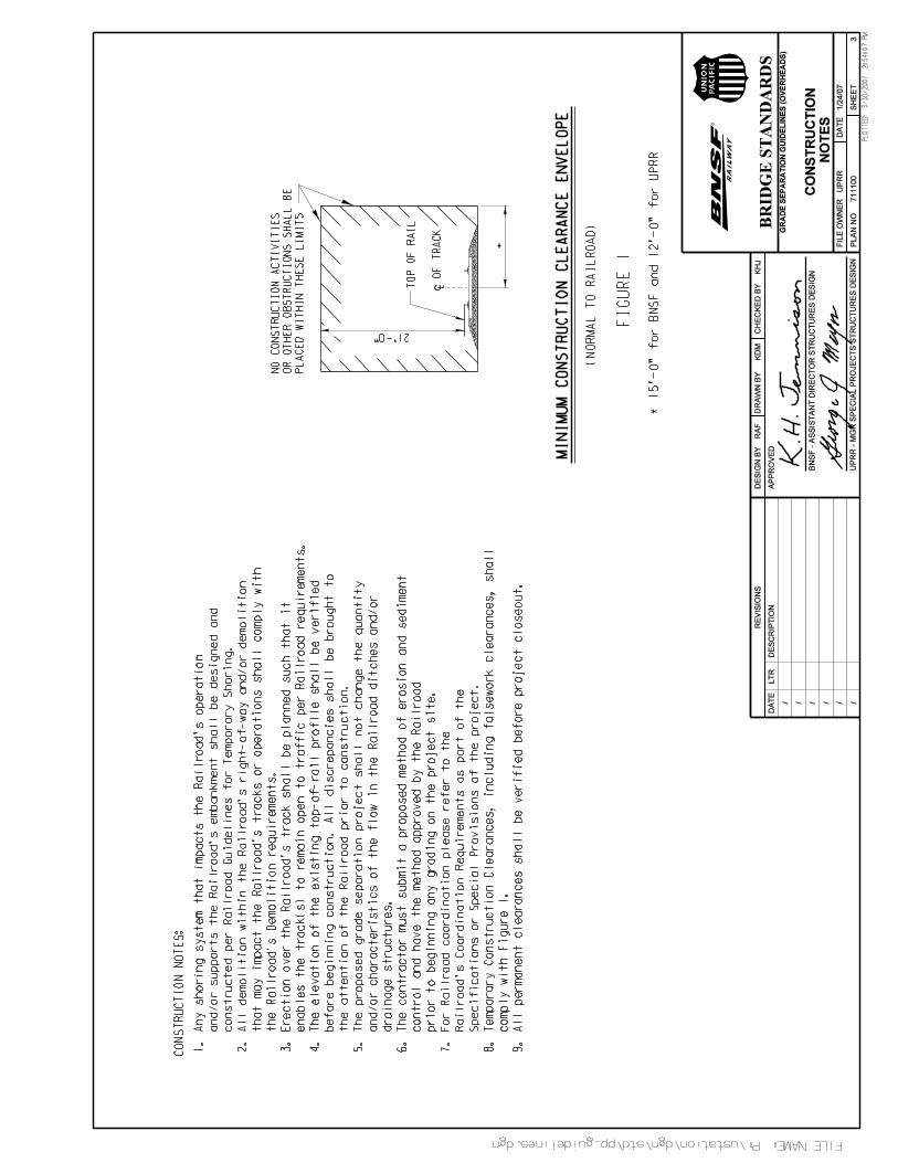
4.4.1.1 Temporary Vertical Construction ClearancesA minimum temporary vertical construction clearance of 21 feet measured above top of high rail for all tracks shall beprovided. The 21 foot temporary vertical clearance shall not be violated due to deflection of formwork. Greatertemporary vertical clearances may be required. The temporary vertical clearances are subject to Railroad localoperating unit requirements.
4.4.1.2 Temporary Horizontal Construction ClearancesA minimum temporary horizontal construction clearance of 15 feet for BNSF and 12 feet for Union Pacific, measuredperpendicular from the centerline of the nearest track, to all physical obstructions including but not limited toformwork, stockpiled materials, parked equipment, bracing or other construction supports, shall be provided.Temporary horizontal construction clearance shall provide sufficient space for drainage ditches parallel to thestandard roadbed section or provide an alternative system that maintains positive drainage.
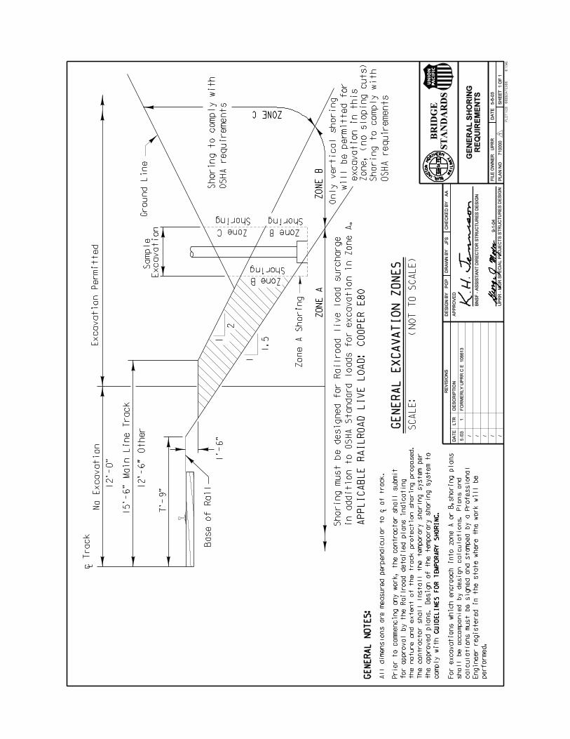
4.4.2 ShoringAll temporary shoring systems that impact Railroad operations and/or support the Railroad embankment shall bedesigned and constructed per Railroad Guidelines for Temporary Shoring.
4.4.3 DemolitionAll demolition within the Railroad right-of-way, which will impact Railroad tracks or operations, shall comply withRailroad demolition requirements.
4.4.4 ErectionErection over the Railroad right-of-way shall be designed to cause no interruption to Railroad operations. Erectionplans shall be developed such that they enable the track(s) to remain open to train traffic per Railroad requirements.
4.4.5 FalseworkFalsework clearance shall comply with minimum construction clearances per Section 4.4.1. The design of allstructural members for falsework shall comply with AREMA as well as Railroad requirements.
4.4.6 VegetationVegetation to be planted on or immediately adjacent to Railroad right-of-way shall not become a fire hazard to track-carrying structures and/or an obstruction to inspection and maintenance of the structures.
4.5 DrainageRailroad corridors are constructed with a drainage system designed to keep runoff away from the tracks and ballast.The drainage system includes the parallel ditches along the embankments as well as the bridges, culverts, siphonsand other structures that convey runoff beneath the tracks or serve as water-equalizing structures. Maintaining theintegrity of the Railroad drainage system is extremely important. The proposed construction shall safely pass highflows and not inhibit low flows or alter the path of the existing drainage system.
GUIDELINES FOR RAILROAD GRADE SEPARATION PROJECTS, January 24, 2007
20
When changes in the drainage system are contemplated by new or replacement construction, or because ofdrainage problems, the system shall be modified as required to accommodate current-condition runoff including anychanges that have occurred in the drainage pattern. The size of the proposed drainage system must conform to theRailroad Hydraulic Criteria described in Section 4.5.2 and 4.5.3.
A complete hydrologic and hydraulic study is required whenever new or additional drainage is added to the Railroadright-of-way, or when a drainage structure is scheduled to be added, removed, modified or replaced. The DrainageReport must be in compliance with the requirements described in these Guidelines.
4.5.1 Erosion and Sediment ControlGeneral plans for construction within the Railroad right-of-way shall indicate the proposed methods of erosion andsediment control. They must specifically provide means to prevent sediment accumulation in the ditches andculverts, to prevent fouling the track ballast and sub-ballast, and to allow free flow of runoff in the drainage systemsduring and after construction.
Corrective and/or mitigative construction due to the fouling of Railroad ballast, sub-ballast, ditches, culverts ordrainage systems will be at the Applicant’s expense. It is the Applicant’s responsibility to document the condition ofthe site before and after construction.
Existing track ditches shall be maintained open at all times throughout the construction period. After the constructionis complete, all erosion and sediment control devices must be removed, all sediment deposits removed, and theentire project area restored to the pre-construction condition.
The Applicant and/or Contractor are responsible for securing the required permits from Local, State and Federalentities. The Applicant and/or Contractor shall furnish the Railroad all copies of the Storm Water Pollution PreventionPlan (SWPPP) and approved permits, if required. Further, these documents shall be available on-site during allconstruction activities. Approval of the erosion and sediment control plan does not relieve the Applicant and/orEngineer-of-Record and Contractor of the ultimate responsibility and liability for compliance with erosion andsediment control requirements.
4.5.2 Hydraulic Criteria for Bridge and Culvert Openings1. Replacement openings shall be sized for two high water events designated “low chord” and “subgrade.”2. Provide the Energy Grade Line (EGL), water surface elevation and velocity flow for both the existing and
proposed hydraulic opening.3. For subdivisions and for any lines in urban areas, regardless of classification, the low chord event is the 50-
year flood and the subgrade event is the 100-year flood.4. For industrial leads and for customer-owned trackage, the low chord event is the 25-year flood and the
subgrade event is the 50-year flood, unless the proposed structure is immediately adjacent to a main linebridge(s). Then, the low chord event and subgrade event shall be as stated above in item 3.
5. If the structure is in a FEMA designated floodplain the water surface elevation for a 100-year event shall bedetermined regardless of line classification.
6. For all cases, the opening will be sized so that the water surface for a “low chord” event will rise no higherthan the crown of the culvert or the low chord of the bridge.
7. For all cases, the opening will be sized so that the energy grade line for a subgrade event will not rise abovethe adjacent subgrade elevation. The subgrade elevation is defined as 2’–3” below base of rail elevation.
GUIDELINES FOR RAILROAD GRADE SEPARATION PROJECTS, January 24, 2007
21
8. Both the Railroad criteria and local flood flow criteria shall be evaluated and the more conservative of thetwo shall be adopted in sizing the replacement.
4.5.3 Hydraulic Criteria for Drainage Systems Parallel to Railroad Tracks1. Culverts and bridges must be designed in accordance with Railroad standard hydraulic criteria described in
Section 4.5.2.2. The 100-year event criteria (EGL no higher than top of subgrade) is to be applied for parallel ditches, open
channels, and encroachments, as well as bridges and culverts. Sufficient lateral and vertical clearancemust be provided to accommodate construction of the standard flat-bottom railroad ditch or a ditch basedupon the EGL for a 100 year event; whichever produces the larger ditch. Anything less than this standard isan exception and must be supported by hydrology and hydraulics.
3. In cases where the Railroad’s standard hydraulic criteria is not applicable due to topography of the track bedand surrounding ground, the Railroad standard flat-bottom drainage ditch (trapezoidal, 10 ft bottom width, aminimum of 2:1 side slopes, with flowline elevation a minimum of 3 ft below the subgrade elevation) must beincorporated.
4. Where acquisition of adequate right-of-way is a limiting factor, or site characteristics justify smaller drainagesystems, a request for variance with sufficient supporting documents must be submitted to the Railroad forconsideration.
5. The applicant must provide hydraulic data (EGL and water surface elevations and velocities) for bothexisting and proposed conditions.
6. Consideration shall be given to the effects of localized contraction scour and mitigation, and if deemednecessary, shall be shown on the design plans.
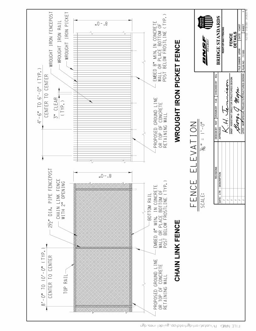
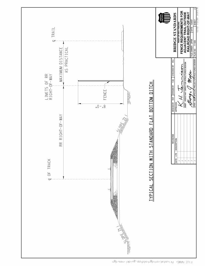
4.6 FencesChain link fencing with openings not exceeding 2 inches should be used in most applications. In some locationswhere the trespassers may cut the chain link fence, a wrought iron picket fence with openings not exceeding 3inches is required. All architectural fencing shall be reviewed and approved by the Railroad. Architectural fencingshall not allow an opening of more than 2 inches and shall be designed to prevent climbing.
Right-of-way fencing shall be provided along the Railroad right-of-way to safeguard the general public and preventtrespassers from entering the Railroad right-of-way. Fencing may need to continue outside the Railroad right-of-waylimits, which will be at the discretion of the Railroad Local Representative. These limits shall be reviewed andapproved by the Railroad’s Central Engineering department. The right-of-way fence shall conform to details asshown on Plan No. 711000, sheet 1.
For overhead grade separation structural fencing, refer to Section 5.4.2.
4.7 Retaining WallsRetaining walls shall be designed to withstand lateral earth and water pressures, any live load and dead loadsurcharge, the self-weight of the wall, temperature and shrinkage effects and earthquake loads.
Retaining walls supporting the Railroad embankment shall be designed in accordance with Railroad requirementsand the general design principles specified in AREMA.
Retaining walls that do not support Railroad embankment shall be designed in accordance with Railroadrequirements and general design principles specified in AASHTO and shall be located outside the Railroad right-of-way limits.
GUIDELINES FOR RAILROAD GRADE SEPARATION PROJECTS, January 24, 2007
22
Barrier rail and fencing for the retaining wall are subject to retaining wall location and Railroad operatingrequirements. Barrier rail and fencing shall be placed in a manner to safeguard the general public while securing theRailroad right-of-way. Barrier rail and fencing shall be designed per Section 5.4.1 and 5.4.2.
4.8 Embankment SurchargeFor all tracks located near a proposed embankment causing the track to be surcharged, the contractor must monitorand record top-of-rail elevations and track alignment. The movement shall be within the limits defined by localRailroad Manager of Track Maintenance (MTM). Displacements exceeding the limits defined by the MTM must beimmediately reported to the Railroad. The track shall be adjusted as needed at the expense of the Applicant.
4.9 UtilitiesRailroad corridors may have utilities that could impact the design, location or even the feasibility of the proposedGrade Separation Project. During the initial study the Applicant shall identify existing utilities within the Railroadright-of-way and plan for proper relocation, protection and installation requirements.
All new or relocated utilities within the Railroad right-of-way will require Railroads prior review and approval. ARailroad Right-of-Entry Agreement (if applicable), per Section 2.3, is required to survey or abandon existing utilitieswithin the Railroad corridor. The Railroad has no obligation to provide property for relocated utilities that do notcomply with Railroad’s standard specifications and requirements including, without limitation, AREMA and theseGuidelines.
No utility attachments will be permitted on Underpass Structures. Existing or future fiber optic lines shall be placedunderground and away from the bridge structure.
The Applicant shall be responsible for the identification, location, protection and relocation of all existing overheadand underground utilities. The design plans for the proposed Grade Separation Project shall included completeinformation on existing and/or proposed relocation of the said utilities.
Appropriate measures for the installation, protection and relocation of fiber optic cables as well as Railroad signaland communication lines shall be addressed in the plans and contract documents. For Railroad requirements andadditional information refer to:UPRR: www.uprr.comFor UPRR Fiber Optic Engineering, “Call Before You Dig”, call 1-800-336-9193For UPRR Grade Crossing/Signal Hotline, call 1-800-848-8715Please refer to UPRR web site for utility review and approval process and Application.BNSF: www.bnsf.comFor BNSF Fiber Optic Engineering, “Call Before You Dig”, call 1-800-533-2891For BNSF Grade Crossing/Signal Hotline, call 1-800-832-5452
Relocation of utilities or communication lines not owned by the Railroad shall be coordinated with the utility owners.The utility relocation plans must then be submitted to the Railroad utility representative for approval.
4.10 Construction Management TeamFor construction of grade separated structures an experienced Construction Management Team will be requiredduring the construction of the bridge structure. Public agencies with qualifying bridge structure staff placed on-siteduring construction will be acceptable; otherwise an outside team must be obtained. Railroad participation duringconstruction is required as indicated in Section 4.11.
GUIDELINES FOR RAILROAD GRADE SEPARATION PROJECTS, January 24, 2007
23
The following are minimum requirements for the Construction Management Team:
• The Applicant is to submit names and qualifications of person(s) to be used in the project and their assignedduties.
• Provide a qualified quality control inspector to be present during fabrication of steel spans and any majorprestressed concrete items.
• Provide a list of past projects that each person has actively worked on, including bridge structures (highway orrail), underground facilities and drainage structures.
• Provide a verifiable list of employment including a current resume for each person in the ConstructionManagement Team.
• Minimum personnel for the Construction Management Team for a typical grade separation structure will consist
of:
1. Project Manager – Primary point of contact, with experience in managing construction projects, forthe Construction Management Team.
2. Resident Engineer – The resident Engineer for the project shall be a registered Civil Engineer withminimum 5 years experience in the field of bridge construction work.
3. Construction Engineer – A Construction Engineer performs complex professional engineering workin the management of major construction projects from design through completion.
4. Construction Inspector – Construction Inspector shall perform continuous inspection of constructionprojects for compliance with plans, specifications and contract documents. The inspector shall befamiliar with concrete and steel bridge construction and have current certifications in the fields ofinspection involved.
• Railroad review and approval of duties, responsibilities, education and experience for each of the above listedmembers of the Construction Management Team will be required.
• All field members of the Construction Management Team are required to have passed and comply with the FRAand Railroad requirements regarding Railroad track safety, bridge fall protection and/or contractor orientationtraining.
4.11 Railroad Site Observation During ConstructionIn addition to the office review of submittals, site observation will be performed by the Railroad at significant pointsduring construction, including but not limited to the following, if applicable:
Underpass Structure1. Pre-construction meeting.2. Shoring systems that impact the Railroad’s operation and/or support the Railroads embankment.3. Demolition.4. Falsework.5. Erection.6. Acceptance observation of any shoofly before placing it in service.7. Foundation installation.8. Reinforcement and concrete placement for main bridge substructure and/or superstructure.9. Shop observation of fabricated steel spans and/or any major pre-stressed concrete items either by
the Railroad or its designated representative.10. Erection of steel or precast concrete bridge superstructure.11. Deck installation.12. Acceptance of waterproofing (prior to placing ballast).
GUIDELINES FOR RAILROAD GRADE SEPARATION PROJECTS, January 24, 2007
24
13. Final observation and acceptance of the bridge structure.
Overhead Structure1. Shoring systems that impact the Railroad’s operation and/or support the Railroads embankment.2. Demolition within the Railroad’s right-of-way.3. Falsework.4. Erection over the Railroad’s right-of-way.5. Final observation and acceptance of the Overhead Structure.
Site observations are not limited to the milestone events listed above; rather, site visits to check progress of the workmay be performed at any time throughout the construction as deemed necessary by the Railroad.
A construction schedule shall be provided to the Railroad Local Representative for their handling with the CentralEngineering department. Inform the Railroad’s Local Representative of the anticipated dates when the listed eventswill occur. This schedule shall be updated as necessary, but at least monthly, so that site visits may be scheduled.Final observation and acceptance of the bridge by the Railroad is required before the contractor leaves the job site.

GUIDELINES FOR RAILROAD GRADE SEPARATION PROJECTS, January 24, 2007
25
5. OVERHEAD STRUCTURES(Roadway Structure Over Railroad)
The preferred Overhead Structure from the standpoint of the Railroad operation is one that will span the entireRailroad right-of-way. The Overhead Structure shall be designed according to Sections 1, 2, 3, 4 and 5 of theseGuidelines, AREMA and any applicable sections of AASHTO. The Railroad strongly discourages construction of anOverhead Structure within or in the vicinity of Railroad yard limits.
5.1 DesignThe proposed Overhead Structure design plans shall allow the Contractor to execute a work plan that enables thetrack(s) to remain in service per Railroad requirements.
The Railroad discourages the use of cast-in-place superstructures and every effort shall be made to utilize astructure type that will not require interruption to Railroad operation during construction. Deck drains, future utilityinstallation and expansion or hinge joints for the Overhead Structure over Railroad tracks or inside Railroad right-of-way are not permitted.
5.1.1 Design PlansDesign plans and calculations shall be in accordance with these Guidelines and submitted per Section 3. Compliancewith these Guidelines will expedite the review and approval process of submittals for the Grade Separation Project.
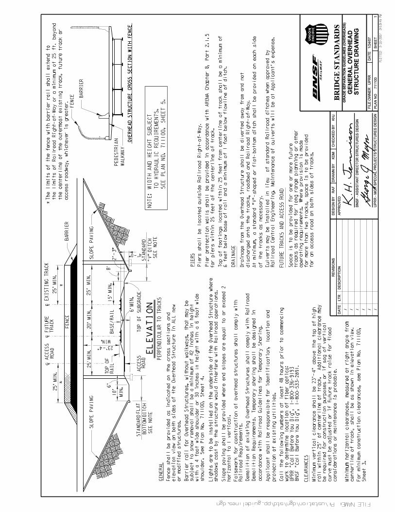
5.2 Permanent ClearancesPermanent clearances, as indicated on Plan No. 711100, sheet 1, are minimum clearances. Permanent clearancesshall accommodate future tracks, future track raises, Access Roads and drainage ditch improvements. Proposedvertical and horizontal clearances shall be adjusted so that the sight distance to any Railroad signals is not reducedunless signals are to be relocated as part of the proposed Grade Separation Project.
The clear zone, within the permanent clearance envelope, shall be clear of all objects such as trees, sign supports,utility poles and other objects.
Permanent clearance shall be correlated with the methods of construction. This ensures that the temporaryconstruction clearances will not be less than the minimum specified in Section 4.4.1.
5.2.1 Permanent Vertical ClearanceThe minimum permanent vertical clearance, per Code of Federal Regulation, shall be 23’ - 4” measured from the topof the highest rail to the lowest obstruction under the structure. The 23’- 4” permanent vertical clearance must not beviolated due to deflection of the superstructure.
Additional vertical clearance may be required for items beyond those shown in the General Overhead Structure onPlan No. 711100, sheet 1. These items include: correction of sag in the track, construction requirements and futuretrack raise.
The profile of the existing top-of-rail, measured 1000 feet each side of proposed Overhead Structure, shall be shownon the plans. If the profile indicates sag at the proposed bridge location, the vertical clearance from the top of thehighest rail to the bridge shall be increased sufficiently to permit raising the track to remove the sag. A note should beadded to the profile stating, “The elevation of the existing top-of-rail profile shall be verified before beginning
GUIDELINES FOR RAILROAD GRADE SEPARATION PROJECTS, January 24, 2007
26
construction.” All discrepancies shall be brought to the attention of the Railroad prior to the commencement ofconstruction.
5.2.2 Permanent Horizontal ClearanceFuture Track per Section 4.1.3 and Access Road per Section 4.1.4, of these Guidelines must be verified with theRailroad in advance of establishing horizontal clearances. The Railroad requires all piers and abutments to belocated outside the Railroad right-of-way limits and to comply with Section 4.1.3 and 4.1.4 of these Guidelines. If thisis not feasible, all piers and abutments shall be located more than 25 feet measured perpendicular from centerline ofnearest existing or future track. Piers within 25 feet, measured perpendicular from centerline of existing or futuretrack, shall be protected per Section 5.5.2 of these guidelines. Absolute minimum horizontal clearance requiringspecial review and approval by the Railroad, and subject to site conditions, shall be 18 feet measured perpendicularfrom the centerline of the track to the face of the pier protection wall.
5.3 Temporary ClearancesThe proposed Overhead Structure shall be designed to satisfy temporary construction clearance requirements perSection 4.4.1 and shown on the plans in accordance with Figure 1 on Plan No. 711100, sheet 3.
5.4 Overhead SuperstructuresThe use of cast-in-place beams is not permitted. The use of stay in place deck forms for falsework between precastconcrete beams or steel girders is encouraged.
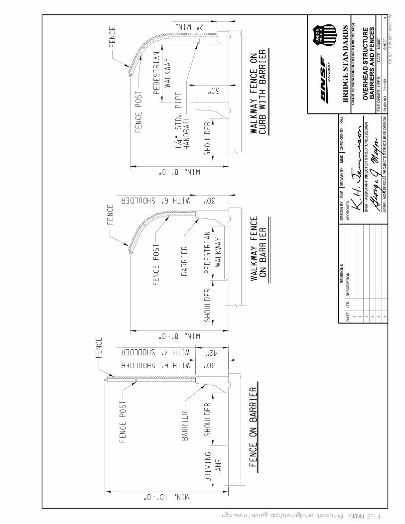
5.4.1 Barrier RailCast-in-place concrete barrier rail without openings and a minimum height of 30 inches shall be provided on bothsides of the superstructure to retain and redirect errant vehicles. The barrier rail shall keep the deck’s storm runofffrom being deposited onto Railroad right-of-way.
Barrier rail for Overhead Structures, which may be subject to snow removal, shall be a minimum of 42 inches inheight with a 4 foot wide shoulder, or 30 inches in height with a 6 foot wide shoulder.
Limits of the barrier rail shall extend to the limits of the Railroad right-of-way or a minimum of 25 feet beyond thecenterline of the outermost existing track, future track or Access Road, whichever is greater.
The barrier rail shall be detailed in accordance with Plan No. 711100, sheet 4.
5.4.2 Fence with Barrier RailFence with barrier rail shall be provided on both sides of all Overhead Structures crossing Railroad right-of-way. Itshall be designed to prevent climbing and provide positive means of protecting the Railroad facility and the safety ofRailroad employees below from objects being thrown by pedestrians or passing motorists.
The limits of the fence with barrier rail shall extend to the limits of the Railroad right-of-way or a minimum of 25 feetbeyond the centerline of the outermost existing track, future track or Access Road, whichever is greater. All parallelOverhead Structures that have a gap of 2 feet or more shall be protected with fencing. Structures with a gap of 2feet or less shall either have the gap covered or be fenced on both sides.
The minimum combined height of a barrier rail with curved fence shall be 8 feet or with a straight fence shall be 10feet. The barrier rail with fence detail shall be in accordance with Plan No. 711100, sheet 4.
GUIDELINES FOR RAILROAD GRADE SEPARATION PROJECTS, January 24, 2007
27
5.5 Overhead SubstructuresAll piers, abutments and embankments shall be located outside of the Railroad right-of-way limits. If this is notpossible, piers and abutments located within the Railroad right-of-way limits must allow room for future track(s) perSection 4.1.3 and Access Road per Section 4.1.4.
Footings for all substructures shall be located and designed to allow a minimum of 12 feet temporary horizontalconstruction clearance measured at a right angle from the centerline of nearest track to the face of shoring tofacilitate footing construction. Temporary shoring shall be designed per Section 4.4.2.
Drilled shafts within the influence of track surcharge shall be designed and constructed with a casing to protect thetrack against cave-in, subsidence and/or displacement of the surrounding ground. The casing shall be designed forlive loads due to the Railroad surcharge in addition to all other applicable loads. Drilled shafts shall be designed toallow the drilling operation without impacting Railroad operations.
5.5.1 PiersEvery effort shall be made to place piers outside the Railroad right-of-way or a minimum of 25 feet measuredperpendicular from the centerline of existing or future track to the face of pier.
Piers within 25 feet of the nearest existing or anticipated future track shall be of heavy construction or shall beprotected by a pier protection wall. Refer to Section 5.5.2 for heavy construction requirements.
A Pier footing within 25 feet of the nearest existing or future track shall be a minimum of 6 feet below the base of rail.This will allow the Railroad to modify their longitudinal drainage system in the future and/or provide an unobstructedarea for placing signal, fiber optic or other utilities.
For piers with 25 feet of clearance from centerline of nearest existing track and located within the Railroad right-of-way, the Railroad requires language in the proposed Agreement mandating the Applicant to fund the construction ofpier protection walls on the bridge piers should they ever be required due to additional trackage being constructed bythe Railroad or for any other legitimate reason. The Applicant shall also be responsible for modification to the pierprotection wall if deemed necessary by the Railroad in the future.
Inside guardrail shall be required, between rails, for all piers located within 25 feet from the nearest existing or futuretrack
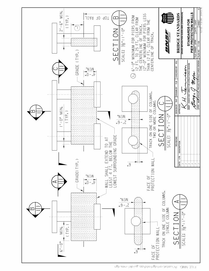
5.5.2 Pier ProtectionThe pier protection wall shall be designed to resist the impact and redirect equipment in case of derailment. Bothsides of the pier shall be protected in locations where tracks are within 25 feet on both sides of the pier.
If seismic criteria are considered, pier design may require column isolation with the wall supported on an independentfooting.
All replacement or modified structures shall comply with AREMA requirements for pier protection walls.
In locations where pier columns and protection walls interfere with drainage, an alternative drainage facility shall beprovided to collect and carry water to a drainage system.

GUIDELINES FOR RAILROAD GRADE SEPARATION PROJECTS, January 24, 2007
28
AREMA defines a pier of heavy construction as: “Cross-sectional area equal to or greater than that required for thepier protection wall and the larger of its dimensions is parallel to the track”. For a single column the minimum cross-sectional area is 30 sq. ft. (12’ length x 2.5’ width = 30 sq. ft.). Columns with 30 square feet of cross sectional areamust have the larger dimension parallel to the track; for example, a 5’ x 6’ column with the 6’ dimension parallel tothe track is considered as heavy construction.
The Pier Protection detail shall be in accordance with Plan No. 711100, sheet 6.
5.5.3 AbutmentsAll abutment slopes, mechanically stabilized earth walls and abutment structures shall be located outside Railroadright-of-way.
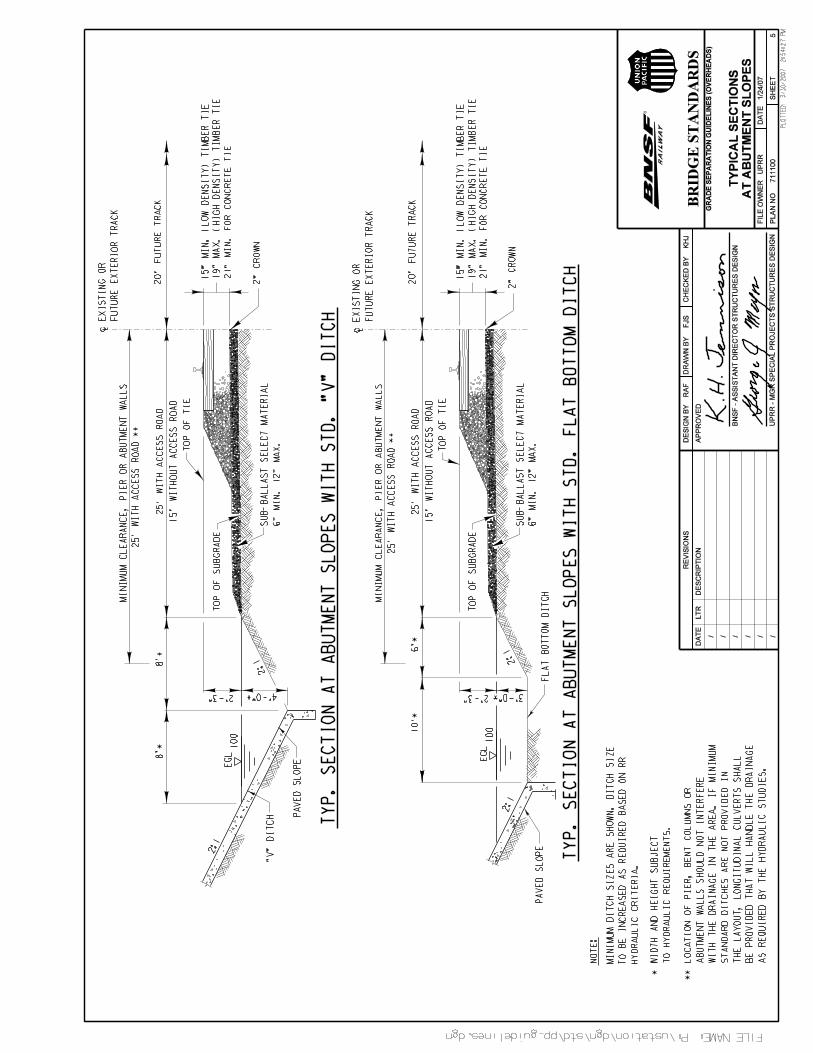
Slope layout shall provide for the minimum drainage ditch(es) or culverts required by hydraulic studies in the area;see Plan No. 711100, sheets 1 and 5 for details. The toe of the slope shall terminate at the bottom of drainage ditchand must have a cut-off wall as required to protect the slope from erosion. In all cases, the toe of slope shall bebelow the finished track or roadway subgrade.
Top of paved slopes shall extend a minimum of two (2) feet past the abutment wall face, and terminate with either acurb or gutter to divert runoff. Paving shall have a prepared sub-base and filter fabric. Reinforced concrete orgrouted rip-rap, with a minimum thickness of 4 inches, shall be placed on prepared sub-base and filter fabric.
5.6 LightingAll new or modified Overhead Structures exceeding 80 feet in width shall provide a lighting system to illuminate thetrack area. However, subject to the Railroad Local Representative, lighting shall be provided for all structures lessthan eighty (80) feet in width in areas where switching is performed or where high vandalism and/or trespassing havebeen experienced. Care shall be taken in lighting placement such that trains will not mistake the lights for trainsignals nor shall they interfere with the train engineer’s sight distance for existing signal aspects. All lights shall bedirected downward.
Provide temporary lighting for all falsework and shoring areas.
The minimum lighting design criteria shall be an average of one (1) foot-candle per square foot of structure at theRailroad tracks. Use Holophane module 600 underdecking type luminaries or equal as required. Fixtures shall beinstalled on the column walls or caps of the Overhead Structure without reducing the minimum horizontal and verticalclearances.
Maintenance of lights shall be the responsibility of the Applicant. Access to perform any maintenance for lights shallbe coordinated with the local Railroad operating unit.
Structures with separation over ten (10) ft. from each other shall be considered as independent structures for thepurposes of lighting.
5.7 Drainage and ErosionDrainage from Overhead Structures shall be diverted away from the Railroad right-of-way at all times. Scuppersfrom the deck shall not be permitted to discharge runoff onto the track or Access Road areas at any time. If drainageof the deck uses downspouts in the columns they shall be connected to the storm drain system or allowed to draininto drainage ditches. Concrete splash blocks or aggregate ditch lining will be required at the discharge area ofdownspouts. Downspouts shall be behind the face of all piers.
GUIDELINES FOR RAILROAD GRADE SEPARATION PROJECTS, January 24, 2007
29
If the layout of abutments, piers or columns with protection walls interferes with the drainage ditches, the designershall provide an alternative method of handling the longitudinal drainage based on a hydraulic study. This mayconsist of pipe culverts.
Track drainage ditch limits shall be shown to scale on the project plans and show the distance from the centerline ofnearest track. A typical cross section detail shall be shown on the plans.
If the proposed bridge structure will not change the quantity and characteristics of the flow in Railroad ditches anddrainage structures, the plans shall include a general note stating so.
Lateral clearances must provide sufficient space for construction of the required standard ditches parallel to thestandard roadbed section. Should the proposed construction change the quantity and/or characteristics of flow in theexisting ditches, the ditches shall be modified as required to handle the increased runoff. The size of ditches will varydepending upon the flow and terrain and should be designed accordingly.
All drainage systems shall be in compliance with Section 4.5.2 and 4.5.3 and Erosion and Sediment Controls shall bein compliance with Section 4.5.1.
GUIDELINES FOR RAILROAD GRADE SEPARATION PROJECTS, January 24, 2007
30
6 UNDERPASS STRUCTURES(Railroad Structure Over Roadway)
The most desirable Grade Separation Structure from the standpoint of the Railroad is an Overhead Structure. TheApplicant shall justify the use of an Underpass Structure in detail. The Underpass Structure shall be designedaccording to Sections 1, 2, 3, 4 and 6 of these Guidelines, the current edition of AREMA and any applicable sectionsof AASHTO. The Railroad strongly discourages construction of an Underpass Structure within or in the vicinity ofRailroad yard limits.
6.1 DesignThe proposed Underpass Structure design plans shall allow the Contractor to execute a work plan that enables thetrack(s) to remain in service per Railroad requirements. The proposed structure shall be designed so there is nointerruption to the Railroad’s operation during construction.
The Railroad discourages the use of structures that are not listed in Section 6.8.1 as an acceptable superstructuretype. The use of Railroad standard spans where possible is encouraged. Only simple spans with ballast decks areallowed. Cast-in-place concrete superstructures are unacceptable.
6.1.1 Design LoadsThe proposed Underpass Structure shall be designed for the following loads:
• Live load and Impact as specified in AREMA. For multiple track structures, live load shall be calculated based onthe assumption that the track(s) can be located anywhere on the bridge with the horizontal clearance to thehandrail defined in Section 6.6.1, and a maximum track spacing of 13 feet. For actual track spacing refer toSections 4.1.2 and 4.1.3.
• Dead load shall include up to 30 inches of ballast from top of deck to the top of tie and all other applicable deadload.
• Seismic design shall comply with the criteria of the current edition of AREMA, Chapter 9 - Seismic Design forRailway Structures.
• Additional loads shall be applied as specified in Chapters 8, 9, and 15 of AREMA, as applicable.
6.1.2 Design Plans and CalculationsDesign plans and calculations shall be in accordance with these Guidelines and submitted per Section 3. Compliancewith these Guidelines will expedite the review and approval process of submittals for the Grade Separation Project.
6.1.3 Concrete RequirementsAll concrete material, placement and workmanship shall be in accordance with Chapter 8 of the current edition ofAREMA and the following:
1. Minimum Compressive Strength – 4000 lb. per square inch at 28 days.2. Exposed surfaces shall be formed in a manner that will produce a smooth and uniform appearance without
rubbing or plastering. Exposed edges of 90 degrees or less are to be chamfered ¾” x ¾”. Top surface tohave a smooth finish, free of all float or trowel marks with the exception that a broom finish be used on allwalkway surfaces.
3. Concrete shall be proportioned such that the water-cementitious material ratio (by weight) does not exceedthe values in AREMA Table 8-1-9. Precast concrete must contain a minimum of 610 pounds of cementitiousmaterial per cubic yard of concrete. Cast-in-place concrete must contain a minimum of 565 pounds of

GUIDELINES FOR RAILROAD GRADE SEPARATION PROJECTS, January 24, 2007
31
cementitious material per cubic yard of concrete. If fly ash is used with cement it shall be limited to 15% ofcementitious material.
4. Cement shall be Type I, II or III Portland Cement per ASTM C150.5. Course aggregate shall be size no. 67.6. Fine aggregate shall be natural sand.7. Admixtures, other than air entrainment, shall not be used without approval by the Railroad.8. Membrane curing compound shall conform to ASTM C309 Type 2.9. Apply ThoRoc Epoxy Adhesive 24LPL or approved alternate before placing new concrete against hardened
surfaces.10. For precast elements, the fabricator shall stencil the fabricator’s name, date of fabrication, the bridge
number, lifting weight and piece mark on each component.11. The production facility must be pre-certified. Production procedures for the manufacture of precast
members shall be in accordance with AREMA and the current edition of the Precast Concrete Institute’sManual MNL 116 for Quality Control.
12. Dimensional tolerances governing the manufacture of precast members shall conform to Division VI,Section 6.4.6 of the Precast Concrete Institute’s Manual MNL 116 for Quality Control. Tolerance forlocation of lifting devices shall be ± ½”.
13. The area around all lifting loops shall be recessed so that the loops can be removed to a depth of ¾” andgrouted. Properly designed lift anchors are acceptable in lieu of lifting loops.
14. The fabricator will be responsible for the loading and properly securing the precast concrete members forshipment. All concrete components shall be made available, at the Railroad’s discretion, for inspection bythe Engineer-of-Record and the Railroad at the fabricator’s plant prior to shipment.
15. Foam used to create internal voids in a precast concrete member, such as in box beams, shall be securelytied down to prevent displacement during concrete placement.
6.1.4 Reinforcing Steel Requirements1. Reinforcing Steel shall be deformed, new billet bars per current ASTM A615 Specifications and meet Grade
60 requirements.2. Reinforcing Steel requiring field welding or bending shall conform to ASTM A706 Specifications, Grade 60.3. Fabrication of reinforcing steel shall be per Chapter 7 of the CRSI Manual of Standard Practice.
Dimensions of bending details shall be out to out of bars.4. Reinforcing steel is to be blocked to proper location and securely wired against displacement. Tack welding
of reinforcing is prohibited. Minimum concrete cover not otherwise noted shall meet current AREMArequirements.
6.1.5 Prestressing Strand Requirements1. Prestressing strand shall be seven wire, uncoated and low relaxation which is in accordance with the
requirements specified in ASTM A416, ACI 318 and AREMA Chapter 8.2. The strand shall have an ultimate tensile strength of 270 ksi.
6.1.6 Structural Steel Requirements1. All major elements subjected to railroad live load shall conform to the following minimum specifications,
except as otherwise noted:
a. Painted structures: ASTM A709 Grade 50,b. Unpainted structures: ASTM A709 Grade 50W.
2. All bolted connections shall be made with high strength bolts.
GUIDELINES FOR RAILROAD GRADE SEPARATION PROJECTS, January 24, 2007
32
3. Material over 4 inches in thickness that is subject to railroad live load shall conform to the followingspecifications:
a. Painted structures: ASTM A572 or ASTM A588.b. Unpainted structures: ASTM A588.
4. Elements not subjected to direct railroad live load (intermediate stiffeners, lateral bracing, diaphragms,ballast curbs, etc.) shall conform to the following specifications:
a. Painted structures: ASTM A572 Grade 50, ASTM A36 or ASTM A992.b. Unpainted structures: ASTM A588.
5. Steel bridge deck shall conform to A709 specifications, Grade 36.6. Deck cover plates and closure plates may be per ASTM A36 specifications.7. Anchor rods/bolts shall conform to ASTM F1554 specifications.8. End welded studs shall be C1015, C1017 or C1020 cold drawn steel, which conforms to ASTM A108
specifications.9. Cover plate, closure plates and anchor rods/bolts shall be galvanized after fabrication in accordance with
ASTM A123, thickness Grade 100.10. Anchor rod washers shall be zinc coated in accordance with ASTM A153 specifications.
6.2 Future Track and Access RoadIt is required to verify the need and requirements for future tracks and/or Access Road for each project. Future trackshall be in accordance with Section 4.1.3. Access Roads shall be in accordance with Section 4.1.4 and 6.2.1.
6.2.1 Access to Underpass StructureFor all Underpass grade separation structures, access to each end of the bridge shall be provided for Railroad off-track maintenance equipment. Access may consist of a road on the bridge, a road on a separated bridge or aroadway with turnarounds.
If the bridge maintenance Access Road is part of the main railway structure, the structure shall be designed forCooper E-80 live load to accommodate any future track needs or modifications. A removable concrete barrier shallbe provided to separate the nearest track from the Access Road by retaining the ballast. If the bridge maintenanceaccess is a completely separate structure it shall be designed for AASHTO HS25-44 live load. The Access Roadshall accommodate one 12 foot wide lane with curbs and railing.
If a bridge maintenance structure is not provided, an Access Road with a turnaround shall be designed andconstructed in conjunction with the grade separation bridge structure. The turnaround pad shall start no further than30 feet from the end of the bridge structure with the embankment shoulder a minimum of 60 feet from centerline oftrack. The radius for the turnaround shall be a minimum of 50 feet. Roadway grade shall not exceed 10% and shallterminate at the sub-ballast elevation. The roadway shall have sufficient width to provide for one 12 foot wide road,drainage ditch and shoulder. The turnaround pad and roadway shall be sloped to drain away from the track and carrythe water to a drainage system or existing Railroad right-of-way ditches.
Access Road with a bridge maintenance structure or turnaround shall be shown in the 30% submittal and thecomplete design shall be included in all subsequent submittals.
6.3 SkewThe preferred angle of intersection between centerline of track and the centerline of bridge supports, transverse tothe track, is 90 degrees. The minimum angle that will be allowed between the centerline of the track and the
GUIDELINES FOR RAILROAD GRADE SEPARATION PROJECTS, January 24, 2007
33
centerline of bridge supports, transverse to the track, is 75 degrees for a Concrete Superstructure and 60 degreesfor a Steel Superstructure.
Align bridge piers and abutments as required to comply with the above maximum skew limitations. Tie rods,diaphragms and approach slabs shall be designed per Section 6.8.10.1, 6.8.8.1 and 6.4, respectively.
Where conditions preclude compliance with these skew requirements, the skew proposal will require specialstructural consideration and proof of adequacy.
6.4 Approach SlabOn skewed abutments an approach slab is required. The bridge end of the approach slab shall be skewed anddoweled with the abutment while the other end of the approach slab is perpendicular to the centerline of track toinsure uniform subgrade stiffness for the ties immediately adjacent to the bridge. The approach slab shall beconstructed symmetrically to the centerline of the track and shall be a minimum of 12 feet wide and extend parallel tothe track a minimum of 3 feet beyond the back edge of the abutment.
6.5 Structure SeparationHorizontal separation between Railroad structures or Railroad and Access Road structures shall be minimum of 5feet clear. All other structure separations shall be in accordance with Section 4.3.
6.6 ClearancesPermanent clearances shall be correlated with the methods of construction to ensure compliance with the temporaryclearances specified in Section 4.4.1.
6.6.1 Permanent Vertical ClearanceUnderpass Structures shall be designed to ensure that the structure will be protected from oversized or unauthorizedloads by providing sufficient vertical clearance and protective devices unless otherwise specified by the Railroad.Provide a minimum vertical clearance over the entire roadway width for all new or reconstructed structures asfollows:
• 16’-6” for steel superstructure with 5 or more beams or 4 or more deck plate girders per track.• 17’-6” for concrete superstructure or steel through plate girders with bolted bottom flanges.• 20’-0” for steel through plate girders without bolted bottom flanges.The vertical clearance must not be violated due to the deflection of the superstructure.
Variations from vertical clearance defined above shall be submitted to the Railroad for approval. The variance will beconsidered if the Railroad structure is not the lowest structure within the roadway network. All proposed structureswith substandard vertical clearances shall be designed per Section 6.7.
If resurfacing or any other activity is to be performed below the Underpass Structure, the owner of the roadway mustsubmit a request for approval from the Railroad. This request must provide the existing measured and postedclearances of the structure and the proposed configuration after work is completed.
The owner of the roadway shall be responsible for graffiti removal and for posting and maintaining the clearancesand any advance notifications the roadway requires. No sign shall be attached to the Railroad bridge.

GUIDELINES FOR RAILROAD GRADE SEPARATION PROJECTS, January 24, 2007
34
6.6.2 Permanent Horizontal ClearanceThe horizontal clearances from the centerline of the nearest track to any bridge component shall, in all cases,conform to AREMA requirements except that in curved track the minimum increase in clearance shall be 6 inches.Proposed structures that accommodate multiple tracks, future tracks and existing tracks having a spacing less than20 feet, shall be designed for a minimum of 20 foot spacing measured centerline to centerline.
6.6.3 Temporary ClearancesThe proposed Underpass Structure shall be designed to satisfy temporary construction clearance requirements perSection 4.4.1, which shall be shown on the plans in accordance with Figure 1 on Plan No. 711100, sheet 3.
6.7 Sacrificial Beams, Fascia Beams and Impact Protection DevicesAll structures with vertical clearances less than defined in Section 6.6.1 shall be protected with a sacrificial beam.Access to the sacrificial beam shall be blocked on both ends and the sacrificial beam shall be located to safeguardthe bridge from oncoming vehicles.
Sacrificial beams shall be steel shapes (wide flange or hollow structural sections) and of sufficient strength to limithorizontal deflection, caused by the impact from oversized vehicles or loads, to 6 inches. The sacrificial beams shallalso be securely anchored with cables at each end to prevent them from falling, and its soffit shall be at least 2inches below the bridge soffit.
Concrete fascia beams used as walkways shall be installed adjacent to the proposed structure and may also serveas a sacrificial beam. If a concrete fascia beam is used as a sacrificial beam it shall have a 6” x 6” x 1” embeddedsteel angle facing oncoming traffic and shall be adequately anchored to the bridge seats at an elevation at least 2inches below the bridge soffit.
All concrete spans, where sacrificial beams are not required, shall be protected with impact protection devicesinstalled over the full width of traveled lanes and attached to the bridge soffit. See Plan No. 711200, sheet 13.
6.8 SuperstructureThe size of the superstructure must accommodate future track(s) per Section 4.1.3 and Access Road per Section4.1.4. For typical cross sections of superstructures see Plan No. 711200, sheets 2 through 9.
6.8.1 Acceptable Superstructure TypesThe following is a list of Underpass Structure types that are acceptable to the Railroad and listed in the order ofpreference. The Railroad’s preferred superstructure type is the highest listed feasible alternative unless a detailedtype selection report provides justifications that a lower listed alternative is more beneficial to the Railroad and to theproject.
1. Rolled Beams with Steel Plate Deck. There shall be at least five beams per track.2. Steel Plate Girders with Steel Plate Deck. There shall be at least four girders per track.3. Rolled Beams with Concrete Deck. There shall be at least five beams per track.4. Steel Plate Girders with Concrete Deck. There shall be at least four girders per track.5. Railroad Standard Prestressed Precast Concrete Double Cell Box Beams.6. Prestressed Precast Concrete Box Beams, single or double cell for span of 50 feet or less.7. Prestressed Precast Concrete AASHTO Type Beams, (or similar) with Concrete Deck for spans of 50 feet or
less.8. Steel Through Plate Girders with Steel Plate Deck will be considered by the Railroad when conditions
preclude any other structure type.
GUIDELINES FOR RAILROAD GRADE SEPARATION PROJECTS, January 24, 2007
35
Underpass Structures of deck truss or through truss design are discouraged. However, in unusual circumstances,they will be considered by the Railroad if conditions preclude the use of any other type of structure.
6.8.2 Deck Type and WidthIn all cases, when using a steel superstructure the use of a steel deck is preferred. The deck width shall be a functionof future track, Access Road, existing track(s), minimum horizontal clearance per Section 6.6.2 and a minimum of 20foot spacings between centerlines of tracks.
6.8.3 Composite DeckUnder normal working loads, composite action may be expected between a concrete deck and its supporting girdersteel members when shear transfer devices are used. The bottom of the deck slab shall be placed at least one inchbelow the top of supporting steel members. For design purposes, the supporting girders shall be designed to satisfydeflection criteria and carry E65 live, impact and dead loads without utilizing any composite action, and E80 live,impact, and dead loads utilizing composite action. Composite action may be mobilized to satisfy the deflection-length ratio requirement of Chapter 15, Article 1.2.5 of AREMA, provided shear transfer devices are installed. Steeldecks may be utilized in composite action to satisfy the deflection-length ratio requirement. However, compositeaction shall not be assumed to satisfy strength requirements.
6.8.4 Ballast Retainers, Fences and HandrailsBallast retainers must be designed to prevent ballast from falling on the roadway. Handrails with fencing shall beprovided on both sides of the deck and shall meet FRA and OSHA requirements. Handrails and fences shall besimple designs that require minimum maintenance and shall meet clearance requirements of Section 6.6.1. Fencesare required over all roadways, trails and sidewalk areas.
The top of ballast retainer shall be minimum of 30 inches above top of deck if fascia beam is used in accordance withtypical sections shown in Appendix A. If fascia beam is not used, top of ballast retainer shall be 36 inches above topof deck.
6.8.5 WalkwayWalkways on bridges, over highways or other locations where spillage of ballast or lading is possible shall beconstructed of solid material and a curb or toe board shall be provided. In accordance with Section 6.6.1, the cleardistance from centerline of track to the ballast retainer for bridges without a walkway shall be a minimum of 8’-0”. Toprevent cracking under live loads, provide 1/4 inch wide control joints at less than 10 foot spacing on concrete curbs,walkways and ballast retainers.
Ballast section may be used as walkway, at the discretion of the Railroad, provided the permanent horizontalclearances are in accordance with Section 6.6.2. If a solid walkway surface is required, it shall be a minimum of 2’-6”wide and be provided on both sides of the structure.
6.8.6 DrainageA minimum longitudinal grade of 0.2% on the superstructure shall be provided to ensure adequate drainage. Thedesigner may provide drainage toward one end of the structure, or when the structure’s length is excessive, provideadequate deck grades to drain the structure to both ends. If the top-of-rail grade is less than 0.2% over the length ofthe structure then the depth of ballast may be varied along the structure.
The top of the concrete deck shall be sloped a minimum of 0.5% transversely.
GUIDELINES FOR RAILROAD GRADE SEPARATION PROJECTS, January 24, 2007
36
For concrete decks, a longitudinal collection system shall be provided on top of the waterproofing along the face ofparapet or curb to drain water. Longitudinal drains shall be connected to the storm drain system or properlydischarged at the toe of embankment slopes. See Plan No. 711200, sheet 10.
If an approach grade descends toward the bridge, drainage from the approach shall be intercepted by an appropriatesystem so that it will not drain onto the bridge.
Inadequate drainage facilities can severely limit the life span of the superstructure. When designing drainage facilitiesfor a structure two important criteria to keep in mind are:
1. Drains should be constructed of corrosion resistant material and the use of PVC shall not be permitted.2. Drains should not discharge on other bridge elements or traffic passing underneath the structure.
The drip groove located on the bottom of the deck slab or fascia beam shall end 3 feet before the face of theabutment.
6.8.7 WaterproofingWaterproofing and protective panels shall comply with the recommendations of Chapter 8, Part 29 of AREMA. Thewaterproofing shall be one layer of Butyl Rubber or EPDM membrane and shall be bonded to the entire bridge decksurface with adhesive applied in accordance with the recommendations of the membrane manufacturer. A ButylRubber or EPDM membrane shall be 0.06 inches thick, minimum. Field splices shall be the tongue and groove typeper AREMA Chapter 8, Part 29, Detail No.3, Figure 8-29-3. Protective asphalt panels shall be placed in two layerswith total thickness not less than 1 inch and shall be laid with joints staggered. Protective panels shall be bonded tothe membrane and each other. For waterproofing details see Plan No. 711200, sheet 11.
Alternatively, a cold liquid spray on waterproofing meeting AREMA requirements, with a single ½ inch layer ofprotective asphalt panels, may be acceptable to the Railroad.
Six inches of ballast shall be placed over waterproofing immediately upon acceptance by the Railroad. Noconstruction traffic is allowed on waterproofing until the ballast covering is in place. Waterproofing installation shall beobserved and approved by the manufacture’s representative.
6.8.8 Steel SuperstructureThe thickness of structural steel, except for fillers, shall not be less than 3/8 inch. Steel, subject to corrosiveinfluences, shall be of greater thickness than otherwise specified to protect them against deterioration.
The thickness of gusset plates connecting the chords and web members of a truss shall be proportional to the forcebeing transferred but not less than 1/2 inch.
The minimum diameter of high strength bolts shall be 7/8 inch diameter.
Floor beams shall be a minimum of 21 inches in depth.
The allowable bearing pressures as recommended in AREMA Chapter 15 shall be used for steel superstructuresbearing on concrete substructures.
GUIDELINES FOR RAILROAD GRADE SEPARATION PROJECTS, January 24, 2007
37
All fracture critical members as defined by AREMA shall be designated as FCM on the plans. Fracture criticalmembers shall be designed for a minimum service temperature and Charpy V-Notch Toughness as required for thecorresponding zone.
The Designer shall provide details such that all exposed parts will be accessible for inspection, cleaning and painting.Not less than 18 inches of clearance shall be provided between the flanges of parallel lines of beams or girdershaving depths in excess of 38 inches.
All designs must provide drain holes for pockets or depressions that may hold water so that steel areas draineffectively. Structural members shall not be sealed by welding except as approved by the Railroad.
In built-up steel girders, provide at least 2 feet between the web and the flange shop-welded splices.
6.8.8.1 Diaphragms or Cross FramesDiaphragms or Cross Frames shall be provided for all steel spans. Jacking stiffeners or jacking beams are requiredfor all steel structures.
6.8.8.2 Mechanically-Connected: Bottom Flanges and Intermediate StiffenersGirders shall have mechanically-connected bottom flanges and intermediate stiffeners when:• The girder span is over a roadway and the use of two girders per span or track cannot be avoided (such as a
through plate girder). • 20 feet of vertical clearance cannot be provided.
Cover plates, flange elements and intermediate stiffeners shall comply with the following requirements.1. Cover plates of girders with bolted flanges shall be equal in thickness or shall diminish outwardly in
thickness. No plate shall be thicker than the flange angles. The gross area of cover plates in any flangeshall not exceed 70 percent of the total flange. The total flange consists of cover plates, flange anglesdirectly connected to the cover plates and side plates. The area of any flange element (flange angle, coverplate or side plate) shall not exceed 50 percent of the total flange.
2. Flange elements that are spliced shall be covered by extra material equal in section to the element spliced.There shall be enough bolts on each side of the splice to transmit to the splice material the stress value ofthe part cut. Flange angles may be spliced with angles or with a full penetration weld. No two elements shallbe spliced at the same cross section or within the development length of another spliced element. Weldedsplices will not be allowed in plate elements of bolted flanges.
3. All intermediate stiffeners shall have a bolted connection to the web.
6.8.9 Painting of Steel StructuresPainting of steel structures shall comply with the current requirements of AREMA, AASHTO specifications andrecommendations of the Steel Structures Painting Council (SSPC).
Paint shall be applied in accordance with the Manufacturer’s recommendations or as recommended by the SSPC,whichever is most restrictive.
The painting system, including primer and top coats, shall be submitted by the Applicant for review and approval bythe Railroad and must be maintained by the Applicant.
GUIDELINES FOR RAILROAD GRADE SEPARATION PROJECTS, January 24, 2007
38
6.8.10 Concrete SuperstructureLive load distribution for precast prestressed concrete single or double cell box beams shall be in accordance withChapter 8, Part 2, Reinforced Concrete Design, Article 2.2.3.c of AREMA. This means that it shall not be assumedthat the live load is necessarily equally distributed to the number of boxes supporting the tracks.
Box shaped (Single or Double void) or AASHTO type precast prestressed concrete beams for all spans shall bedesigned with end and interior diaphragms. Interior diaphragms shall be spaced equally across the span length.
Strands at the ends of precast prestressed concrete members shall be recessed a minimum of 1 inch into themember and the pocket filled with grout.
For AASHTO type beams, the designer shall provide a minimum of eighteen (18) inches clear between the bottomflanges to accommodate inspection and repair.
6.8.10.1 Tie RodsTransverse tie rods shall be provided for all concrete spans utilizing single cell box beams. Transverse tie rods shallbe used at span ends and intermediately spaced at maximum intervals of 25 feet. Wherever possible, transverse tierods in end and interior diaphragms shall be placed perpendicular to the centerline of webs to facilitate application oftransverse post-tensioning.
The minimum size of tie rod shall be 1-1/4 inches in diameter. Tie Rods shall be threaded steel bars with a minimumfy = 36 ksi. Tie rods shall be tensioned as necessary to ensure that all beam sides are in contact without causing anyvertical displacement of the beams from the bearings. The tie rod shall be protected in one of the following ways:
1. Rod, plates and nuts shall be hot dip galvanized per ASTM A123 and A153 specifications.2. All assembly parts left plain but void between rod and hole to be pressure grouted. The tie rod anchor
assembly shall be recessed into the concrete and shall have 1 inch minimum grout cover.
6.9 SubstructurePier and or abutment dimensions must accommodate future track(s) and Access Road per Section 4.1.3 and 4.1.4.
Footings for all substructures shall be located and designed to allow a minimum of 12 feet measured perpendicularfrom centerline of nearest active track to face of shoring to facilitate footing construction. Temporary shoring shall bedesigned per Section 4.4.2.
Cross-hole Sonic Log (CSL) Testing may be required by the Railroad to evaluate the integrity of drilledshafts/caissons. The Plans and Specifications shall include provisions for this testing.
Drilled shafts within the influence of track surcharge shall be designed with temporary casing for protection againstcave-in, subsidence and or displacement of surrounding ground. Casing shall be designed for live load due to theRailroad surcharge in addition to all other applicable loads. Drilled shafts shall be designed to allow the drillingoperation to proceed without impacting the Railroad operation.
6.9.1 PiersColumns shall be at least 0.2H in thickness at the base. Slope the top of bridge seat to drain. If weathering steel isused for the superstructure, detail the bridge seat to minimize water staining concrete surfaces.
Provide a minimum edge distance of 6 inches from edge of masonry plate or bearing to edge of concrete.
GUIDELINES FOR RAILROAD GRADE SEPARATION PROJECTS, January 24, 2007
39
Provide a minimum of 18 inches beyond the outside edge of outermost masonry plate or bearing to end of the pier.
Single column piers shall not be considered for Underpass Structures. Piers with a minimum of two columns shall beprovided. A solid pier wall with minimum of 4 feet thickness is preferable.
Bridge piers adjacent to roadways shall be protected from vehicular traffic as required per AASHTO and StateDepartment of Transportation standards.
6.9.2 AbutmentsSlope the top of bridge seat to drain. If weathering steel is used for the superstructure, detail the bridge seat tominimize water staining concrete surfaces.
The abutments shall be wide enough to satisfy the Railroad standard roadbed. For multiple track bridges, theabutment width shall be sufficient to provide for the standard shoulder, plus 20 feet for each existing or future track.
Provide a minimum edge distance of 6 inches from edge of masonry plate or bearing to edge of concrete.
Sloping embankments in front of abutments shall be paved or have grouted rip-rap on top of filter fabric.
The year of construction shall be shown at the face of abutment backwall. Numbers shall be embedded into theconcrete and be 6 inches size and located where visible.
Wing walls shall be designed to support 2:1 embankment slopes and provide positive ballast containment.
6.10 Sequence of ConstructionIt is essential that the construction proceed with no interference to Railroad operations. Continuity of safe railoperation will be required for the duration of the project. The Applicant should contact the Railroad LocalRepresentative in the preliminary design stages to determine the Railroad operation requirements.
The most effective method for maintaining traffic is to temporarily reroute Railroad traffic around the construction siteusing detour tracks (shooflys). Shooflys shall be designed per Section 4.1.1.
The use of shooflys for the construction of the permanent structures will minimize traffic interference with railroadoperations. However, if construction requires interruption of rail traffic or track and time windows, approval from theLocal Service Unit Superintendent of the area is required. No design shall advance without written approval. Prior tothe start of any construction on Railroad right-of-way, a Railroad Right-of-Entry Agreement (if applicable) is requiredper Section 2.3.
6.11 Construction ExcavationExcavations for construction of footings, piers, columns, walls and other facilities that require shoring to support activetracks shall comply with BNSF/UPRR Temporary Shoring Guidelines
6.12 Temporary StructuresTemporary railroad bridges used for a shoofly must be designed in accordance with AREMA and these Guidelines.Temporary open deck bridges with walkways may be used if a protective cover over the roadway and sidewalks isprovided or if the roadway is closed to traffic during construction.
GUIDELINES FOR RAILROAD GRADE SEPARATION PROJECTS, January 24, 2007
40
7 TRAILS(Non-Vehicular Crossing over or under the Railroad)
All Trails impacting the Railroad shall be designed in accordance with Section 1, 2, 3, 4 & 7 of these Guidelines, theManual of Uniform Traffic Control Devices (MUTCD), AASHTO code and any applicable sections of AREMA.
7.1 At Grade CrossingThe Railroad does not allow at grade Trail crossings. Alternative plans should be considered to avoid crossingRailroad tracks at grade. At grade crossings immediately adjacent to an existing public roadway crossing withexisting Highway Railroad warning devices may be considered. However, all costs associated with the installation ofthe new crossing surface and crossing warning device changes or relocation will be borne by the Applicant. Scope ofproposed crossing work will be determined at a joint diagnostic meeting between the Railroad and Applicant. TheTrail must conform to Railroad and MUTCD requirements.
7.2 Trail Parallel to TrackThe Railroad does not allow Trails parallel to the track on Railroad right-of-way and does not permit the use ofRailroad Access Roads for trail use. Railroad bridges can not be used to serve Trail traffic or support a structureserving Trail traffic. Fences or barriers such as vegetation, ditches, and/or berms shall separate Trails that areoutside the Railroad right-of-way and running parallel to the track to stop trespassers from entering the Railroad right-of-way. See Plan No. 711000, sheet 2.
7.3 Grade Separated CrossingConsider the use of existing structures to cross the Railroad tracks. In accordance with Homeland Securityrequirements some Railroad sites and structures are off limits for Trail use and crossing.
7.3.1 Overhead Crossing (Trail over Railroad)New and existing Overhead Structures must be designed or modified with a protective curved fence. See Plan No.711100, sheet 4. New Overhead Structures shall be designed per Section 5 of these Guidelines.
7.3.2 Underpass Crossing (Railroad Structure over Trail)The Railroad discourages the construction of new Underpass Structures. If an Underpass Structure is the onlyfeasible structure type for the proposed site, a detailed type selection report must be submitted to justify its use.
7.3.2.1 New Underpass CrossingNew Underpass Structures shall be designed per Section 6 of these Guidelines.
All pipe and concrete box culverts shall be designed per Railroad requirements and any applicable sections ofAREMA. Confined structures are discouraged. To improve safety and sight distance all structures shall be tangentwithout curvature. The clear width and height of pedestrian structures shall be subject to the project site and structurelength. The line of sight, historical security data and lighting shall be used for determining the required size ofopening. Vertical Clearance shall not be less than 8 feet.
7.3.2.2 Crossing Under Existing StructuresAn open deck structure shall be modified to a ballast deck or solid deck structure to maintain a safe crossing under aRailroad structure. If modifying an existing open deck structure is not practical, provide a protective cover over theTrail.
GUIDELINES FOR RAILROAD GRADE SEPARATION PROJECTS, January 24, 2007
41
Protection from falling debris is required for the crossing of pedestrians safely under active rail bridges. Theoverhead protection shall extend a minimum of 30 feet out on each side of the Railroad structure, or further asdesignated by the Railroad’s Central Engineering department. However, the protective cover shall not reduce theexisting hydraulic opening, shall not function as a debris catcher and shall not impact proper inspection of thestructure by Railroad personnel.
Measuring the from bottom of the Railroad structure to the top of the protective cover shall not be less than three feet toallow for inspection and shall not be attached to the structure. If the Applicant can not meet these requirements thenthe Applicant shall provide a removable hatch to allow Railroad personnel to inspect the bridge structure.
The protective cover shall be removable and can be removed, at the Applicant’s expense, without advanced notice ifdeemed necessary by the Railroad.
A protective cover shall be required, meeting the above criteria, for ballast deck bridges unless the superstructuremeets the requirements of Section 6.8.4.
7.4 DrainageThe drainage pattern of the site before and after construction shall be analyzed. Adequate drainage provisions shallbe incorporated into the plans and specifications. Detailed Hydraulic Report may be required subject to site condition.The Hydraulic report must meet the Railroad Hydraulic Criteria per Sections 4.5.2 and 4.5.3.
7.5 FenceThe Applicant shall specify the appropriate fencing to contain the Trail traffic, within the Trail, crossing the Railroadright-of-way. Fence limits are subject to each project site and must be determined on a case by case basis. Refer toSection 4.6 for fence requirements and Plan No. 711000, sheet 1 for fence details.
All Railroad right-of-way fencing, for Trails adjacent to the Railroad right-of-way, must be provided, installed outsideRailroad right-of -way and maintained by the Applicant.
7.6 SignsAll access to Trails crossing railroad track shall be protected with bollard posts and signs prohibiting non-authorizedvehicular access.
All advisory and regulatory signs shall be in compliance with MUTCD and AASHTO. "No Trespassing" signs shall beposted every 500 feet.
7.7 LightingAdequate lighting shall be provided per AASHTO Roadway Lighting Design Guide requirements. Dark confined andisolated Trail crossings hidden from public view may attract illegal activities. Line of sight is extremely important whenvisibility is a matter of safety and security. The lighting design shall account for the impact on train operations.Lighting shall provide visibility for the Trail without directing light toward the train traffic.