
BMX Bike Demo Storyboard
29
1 © 2015 ANSYS, Inc. ANSYS Confidential BMX Bike Demo Storyboard AIM 17.1
Transcript of BMX Bike Demo Storyboard

1 © 2015 ANSYS, Inc. ANSYS Confidential
BMX Bike Demo Storyboard AIM 17.1

2 © 2015 ANSYS, Inc. ANSYS Confidential
Introduction
• This demo illustrates fatigue life analysis in AIM, including interactive geometry parameterization and changes to study the effects of geometry dimensions on fatigue life.
• The design goal is to minimize the weight of a BMX bicycle frame while ensuring that its fatigue life is at least 100,000 cycles, per industry‐standard load tests and safety guidelines. This is done by adjusting the thickness of the frame tubes at discrete increments.
• For simplicity, the frame material is structural steel. Many performance bicycle frames are made of chromoly, an alloy of steel, chromium, molybdenum, and a few other things. One could define a custom material in AIM to simulate the behavior of chromoly for this model.
• All uses of this geometry model must include the statement, “Based on model courtesy of Guilherme Padilha”.

3 © 2015 ANSYS, Inc. ANSYS Confidential
• Select ‘Structural’ template
• Enable ‘Allow model editing’
• Disable ‘Detect contact automatically’
• Enable ‘Compute fatigue results’
• ‘Create Simulation Process’
• Select ‘BMX Bike.scdoc’
Create Simulation Process

4 © 2015 ANSYS, Inc. ANSYS Confidential
Edit Geometry
Based on model courtesy of Guilherme Padilha
Based on model courtesy of Guilherme Padilha
5 © 2015 ANSYS, Inc. ANSYS Confidential
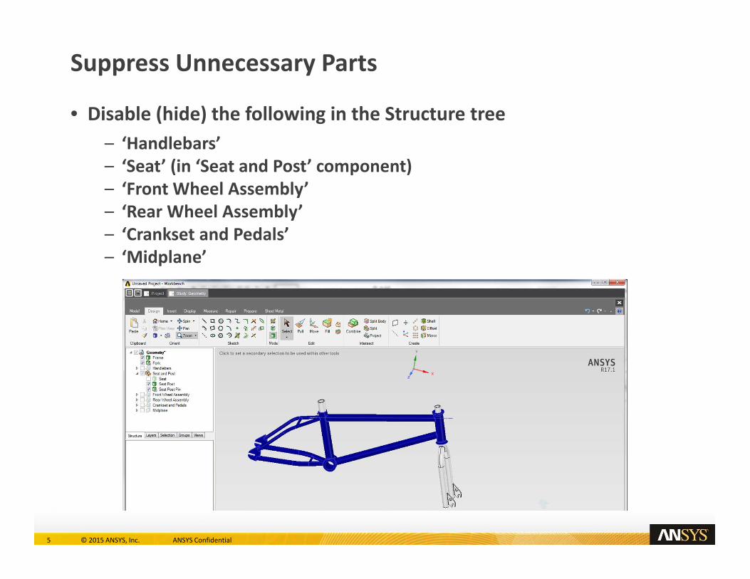
Suppress Unnecessary Parts
• Disable (hide) the following in the Structure tree – ‘Handlebars’ – ‘Seat’ (in ‘Seat and Post’ component) – ‘Front Wheel Assembly’ – ‘Rear Wheel Assembly’ – ‘Crankset and Pedals’ – ‘Midplane’

6 © 2015 ANSYS, Inc. ANSYS Confidential
Create Tube Thickness Parameter (1/6)
• Select inner surfaces of tubes shown in red below – To select interior surfaces, hold Ctrl key, rotate mouse wheel, and click

7 © 2015 ANSYS, Inc. ANSYS Confidential
Create Tube Thickness Parameter (2/6)
• Invoke ‘Pull’ tool
• Click on Measure option

8 © 2015 ANSYS, Inc. ANSYS Confidential
Create Tube Thickness Parameter (3/6)
• Select both outer and inner surfaces of one tube – To select interior surface, hold Ctrl key, rotate mouse wheel, and click

9 © 2015 ANSYS, Inc. ANSYS Confidential
Create Tube Thickness Parameter (4/6)
• Select value for “Minimum distance between objects” in measurement table – Click on ‘2mm’ in right column, second row of table at bottom right

10 © 2015 ANSYS, Inc. ANSYS Confidential
Create Tube Thickness Parameter (5/6)
• Create parameter from driving dimension – Click on blue ‘[P]’ button at bottom right
11 © 2015 ANSYS, Inc. ANSYS Confidential
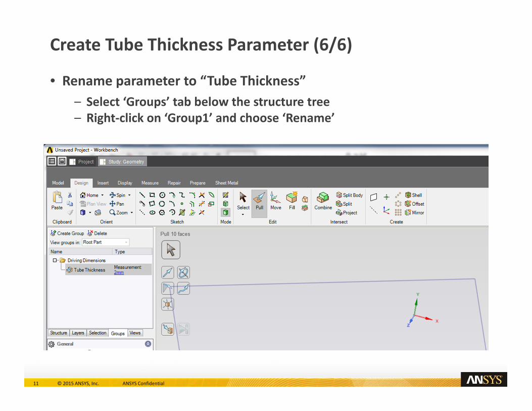
Create Tube Thickness Parameter (6/6)
• Rename parameter to “Tube Thickness” – Select ‘Groups’ tab below the structure tree – Right‐click on ‘Group1’ and choose ‘Rename’

12 © 2015 ANSYS, Inc. ANSYS Confidential
Close Geometry Modeler

13 © 2015 ANSYS, Inc. ANSYS Confidential
• Select ‘Mesh’ task
• Expand ‘Global Sizing’ group
• Change ‘Size function method’ to ‘Curvature’
• Generate mesh
Generate Mesh with Curvature Size Function

14 © 2015 ANSYS, Inc. ANSYS Confidential
• Select ‘Physics’ task
• Select 4 orange faces at right – On rear of frame
• Add Support structural condition
Add Rear Support

15 © 2015 ANSYS, Inc. ANSYS Confidential
• Select 2 orange faces at right – On front fork
• Add Support structural condition
Add Front Support

16 © 2015 ANSYS, Inc. ANSYS Confidential
• Select orange face at right – Top of seat post
• Add Force structural condition – Directional components – Y = ‐1400 N
Add Seat Load

17 © 2015 ANSYS, Inc. ANSYS Confidential
• Select ‘Physics’ task
• Add ‘Interface Generator’
• ‘Generate Interfaces’
Add Contact Interfaces

18 © 2015 ANSYS, Inc. ANSYS Confidential
Confirm Contact Interfaces
• Select ‘Generated contacts (4)’ – Fork – Frame, Seat Post – Frame, Seat Post Pin – Frame (2)

19 © 2015 ANSYS, Inc. ANSYS Confidential
Update Results

20 © 2015 ANSYS, Inc. ANSYS Confidential
• Select ‘Equivalent Stress’
• Hide data panel (CDV) and Workflow
• Select ‘Displacement Magnitude’ – Animate
• Select ‘Fatigue Life’ – Zoom in to seat post area – Note that minimum value is much greater than minimum allowable of 100,000.
Review Results

21 © 2015 ANSYS, Inc. ANSYS Confidential
Edit Geometry

22 © 2015 ANSYS, Inc. ANSYS Confidential
Reduce Tube Thickness to 1 mm

23 © 2015 ANSYS, Inc. ANSYS Confidential
Update Results

24 © 2015 ANSYS, Inc. ANSYS Confidential
Review Fatigue Life Results
25 © 2015 ANSYS, Inc. ANSYS Confidential
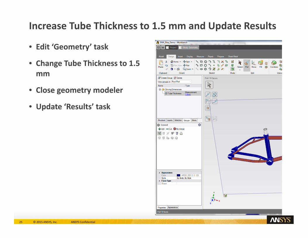
• Edit ‘Geometry’ task
• Change Tube Thickness to 1.5 mm
• Close geometry modeler
• Update ‘Results’ task
Increase Tube Thickness to 1.5 mm and Update Results

26 © 2015 ANSYS, Inc. ANSYS Confidential
Review Fatigue Life Results

27 © 2015 ANSYS, Inc. ANSYS Confidential
• Set the “Calculated minimum” as a parameter
• Click on the Design Point Dashboard icon
Alternative: Design Point Dashboard

28 © 2015 ANSYS, Inc. ANSYS Confidential
Alternative: Design Point Dashboard
• Add the different tube thickness and select ‘Update All.’

29 © 2015 ANSYS, Inc. ANSYS Confidential
Conclusion