
BMS.ppt
70
Building Management System Basics, Functions and Future Trends
-
Upload
bilal-almelegy -
Category
Documents
-
view
216 -
download
0
Transcript of BMS.ppt
8/10/2019 BMS.ppt
http://slidepdf.com/reader/full/bmsppt 1/70
Building Management System
Basics, Functions and Future Trends
8/10/2019 BMS.ppt
http://slidepdf.com/reader/full/bmsppt 2/70
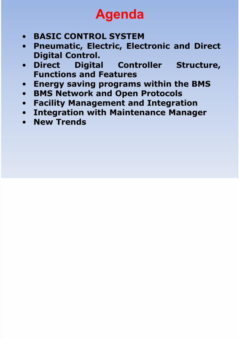
Agenda
• BASIC CONTROL SYSTEM
• Pneumatic, Electric, Electronic and DirectDigital Control.
• Direct Digital Controller Structure,Functions and Features
• Energy saving programs within the BMS • BMS Network and Open Protocols
• Facility Management and Integration
• Integration with Maintenance Manager
•
New Trends

8/10/2019 BMS.ppt
http://slidepdf.com/reader/full/bmsppt 3/70
A ert M. Butz nvents t ethermostat
8/10/2019 BMS.ppt
http://slidepdf.com/reader/full/bmsppt 4/70
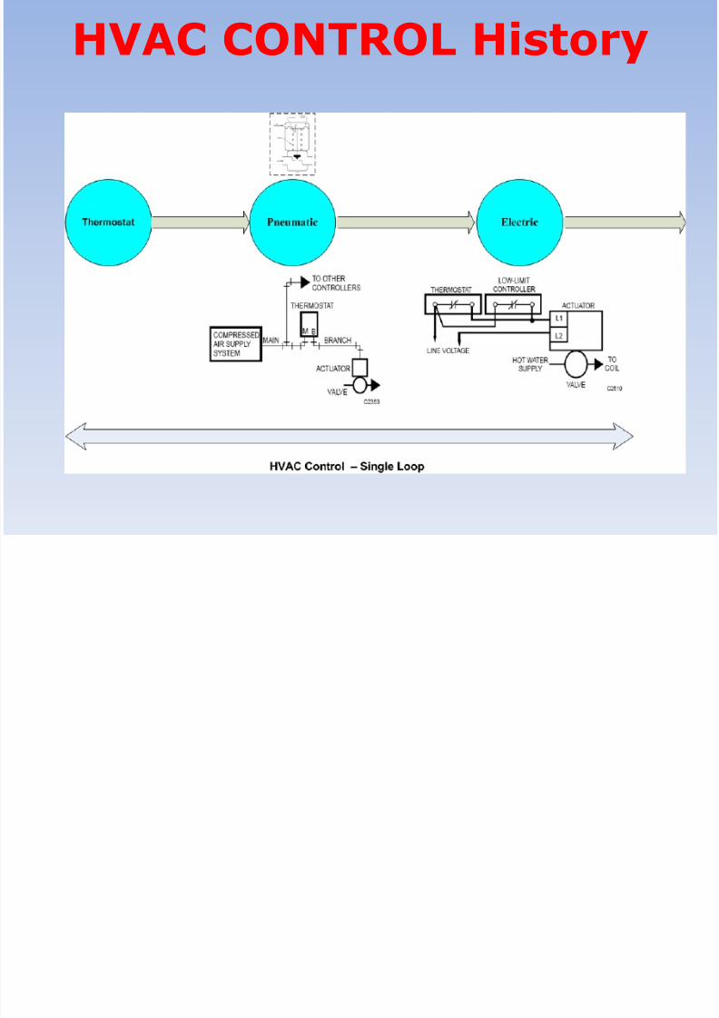
HVAC CONTROL History
8/10/2019 BMS.ppt
http://slidepdf.com/reader/full/bmsppt 5/70
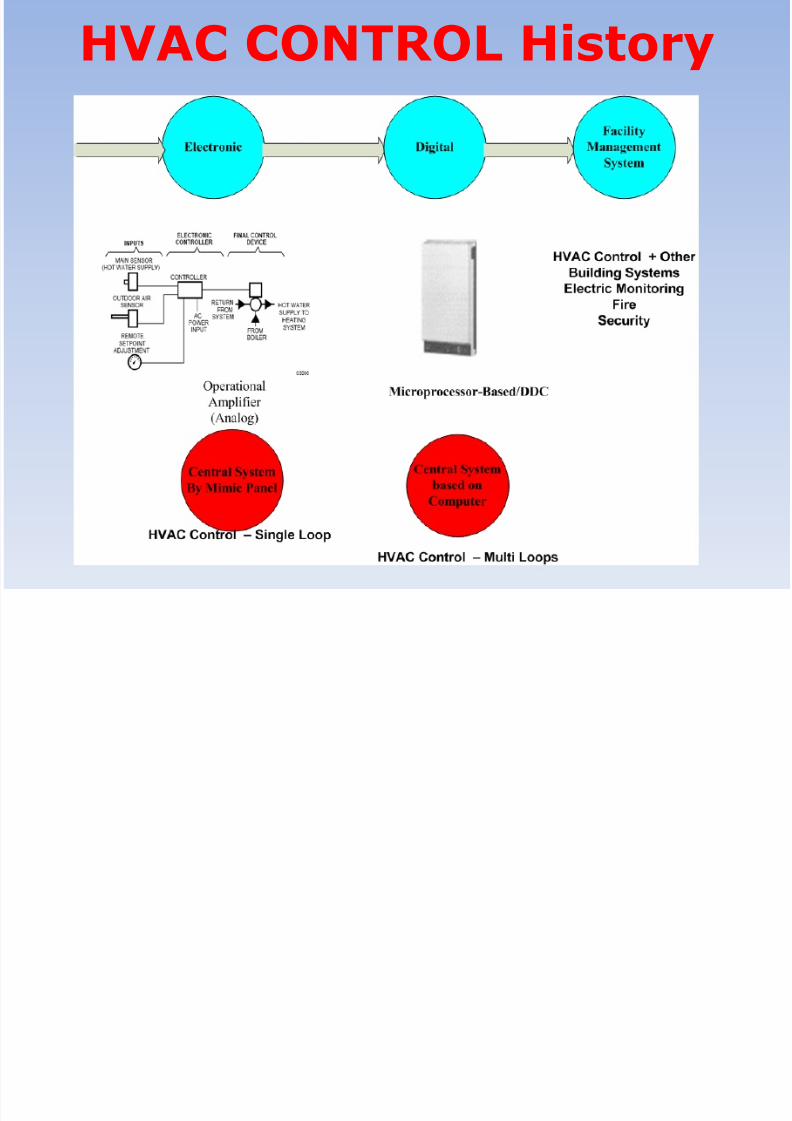
HVAC CONTROL History

8/10/2019 BMS.ppt
http://slidepdf.com/reader/full/bmsppt 6/70
Function of HVAC controls
A Heating, Ventilating, and Air-Conditioning (HVAC)
Control system operates the mechanical equipment
(boilers, chillers, pumps, fans, etc.) to maintain the
proper environment in a cost-effective manner. Aproper environment is described with four variables:
temperature, humidity, pressure and ventilation.
Temperature —

8/10/2019 BMS.ppt
http://slidepdf.com/reader/full/bmsppt 7/70
Function of HVAC controls
The comfort zone for temperature is between 68°F
(20°C) and 75°F (25°C).Humidity —The comfort zone for humidity is between
20% relative humidity (RH) and 60% RH
Pressure . The rooms and buildings typically have a
slightly positive pressure to reduce outside air
infiltration.
Ventilation . Rooms typically have several complete air
changes per hour. Indoor Air Quality (IAQ) is animportant issue.
8/10/2019 BMS.ppt
http://slidepdf.com/reader/full/bmsppt 8/70
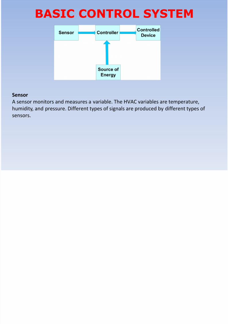
BASIC CONTROL SYSTEM
Sensor
A sensor monitors and measures a variable. The HVAC variables are temperature,
humidity, and pressure. Different types of signals are produced by different types of
sensors.

8/10/2019 BMS.ppt
http://slidepdf.com/reader/full/bmsppt 9/70
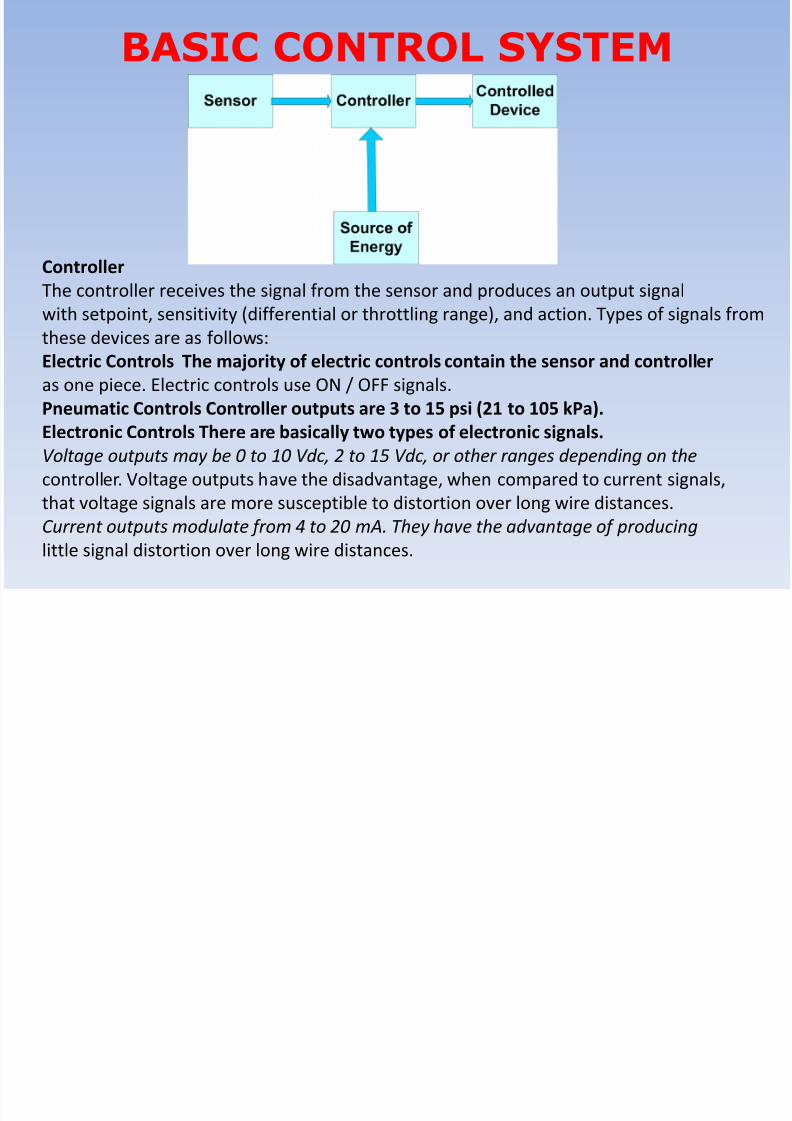
BASIC CONTROL SYSTEM
Controller
The controller receives the signal from the sensor and produces an output signal
with setpoint, sensitivity (differential or throttling range), and action. Types of signals from
these devices are as follows:
Electric Controls The majority of electric controls contain the sensor and controller
as one piece. Electric controls use ON / OFF signals.
Pneumatic Controls Controller outputs are 3 to 15 psi (21 to 105 kPa).Electronic Controls There are basically two types of electronic signals.
Voltage outputs may be 0 to 10 Vdc, 2 to 15 Vdc, or other ranges depending on the
controller. Voltage outputs have the disadvantage, when compared to current signals,
that voltage signals are more susceptible to distortion over long wire distances.
Current outputs modulate from 4 to 20 mA. They have the advantage of producing
little signal distortion over long wire distances.
8/10/2019 BMS.ppt
http://slidepdf.com/reader/full/bmsppt 10/70
BASIC CONTROL SYSTEM
Controller
The controller receives the signal from the sensor and produces an output signal
with setpoint, sensitivity (differential or throttling range), and action. Types of signals from
these devices are as follows:
Electric Controls The majority of electric controls contain the sensor and controller
as one piece. Electric controls use ON / OFF signals.
Pneumatic Controls Controller outputs are 3 to 15 psi (21 to 105 kPa).Electronic Controls There are basically two types of electronic signals.
Voltage outputs may be 0 to 10 Vdc, 2 to 15 Vdc, or other ranges depending on the
controller. Voltage outputs have the disadvantage, when compared to current signals,
that voltage signals are more susceptible to distortion over long wire distances.
Current outputs modulate from 4 to 20 mA. They have the advantage of producing
little signal distortion over long wire distances.
8/10/2019 BMS.ppt
http://slidepdf.com/reader/full/bmsppt 11/70
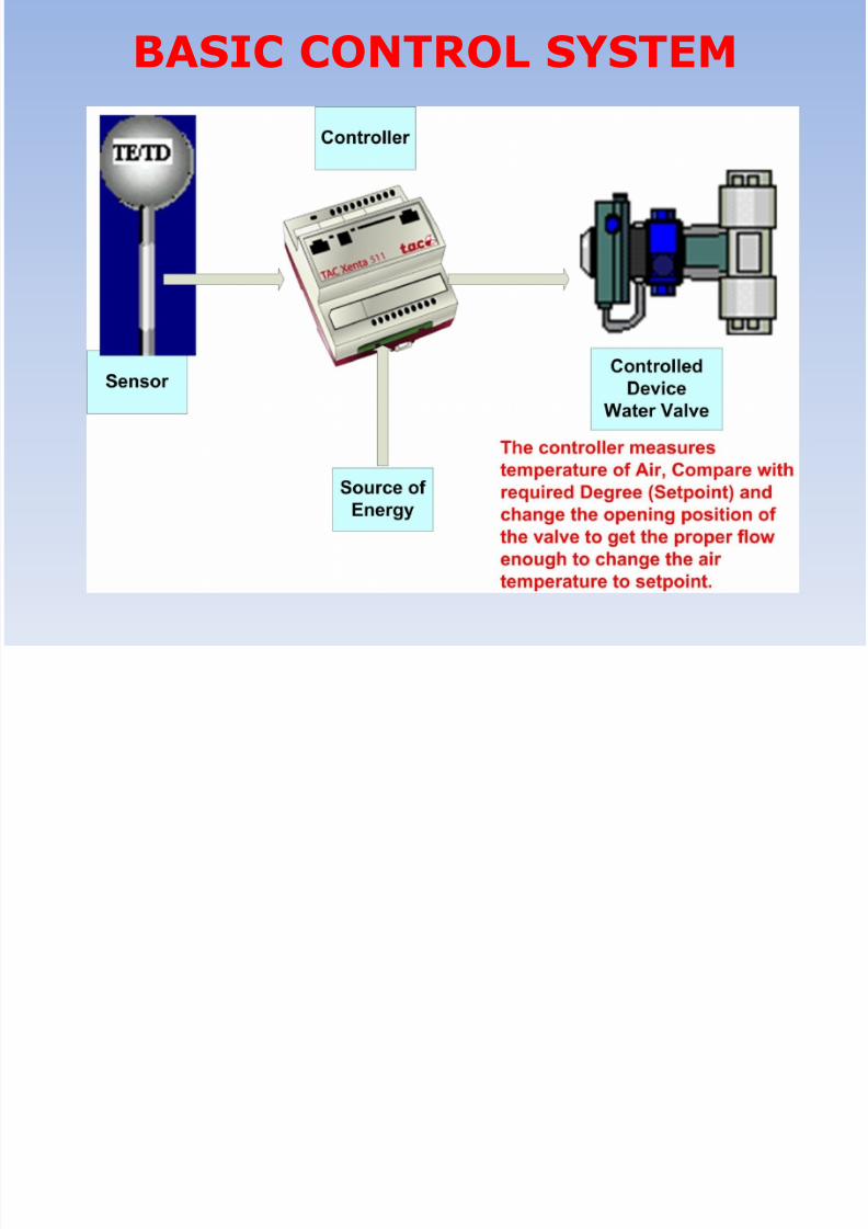
BASIC CONTROL SYSTEM

8/10/2019 BMS.ppt
http://slidepdf.com/reader/full/bmsppt 12/70
BASIC CONTROL SYSTEM
Compressed air from compressor is used to as a source of energy for Pneumatic
Controllers. E ach Pneumatic controller support one control Loop. Currently is Used
for specific applications and service cost is expensive.
8/10/2019 BMS.ppt
http://slidepdf.com/reader/full/bmsppt 13/70
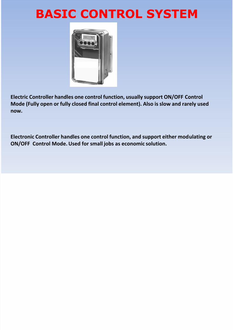
BASIC CONTROL SYSTEM
Electric Controller handles one control function, usually support ON/OFF Control
Mode (Fully open or fully closed final control element). Also is slow and rarely used
now.
Electronic Controller handles one control function, and support either modulating or
ON/OFF Control Mode. Used for small jobs as economic solution.
8/10/2019 BMS.ppt
http://slidepdf.com/reader/full/bmsppt 14/70
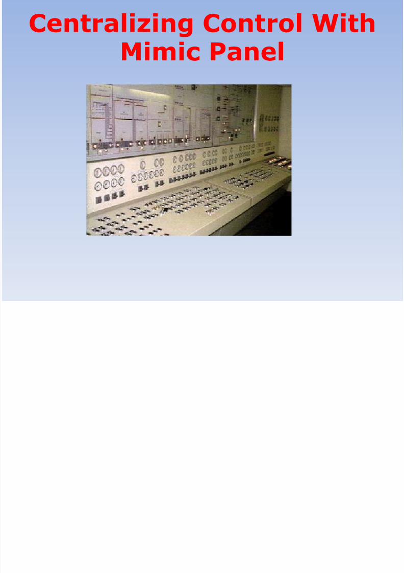
Centralizing Control WithMimic Panel

8/10/2019 BMS.ppt
http://slidepdf.com/reader/full/bmsppt 15/70
Direct Digital Controllers(DDCs)
Direct Digital Controllers is a microprocessor based device, and has a battery backed
memory to hold control programs and operating system, and also Input / Output
connectors to deal with sensors and final control elements.Direct Digital Controllers are the core product for the Building Management System.
8/10/2019 BMS.ppt
http://slidepdf.com/reader/full/bmsppt 16/70
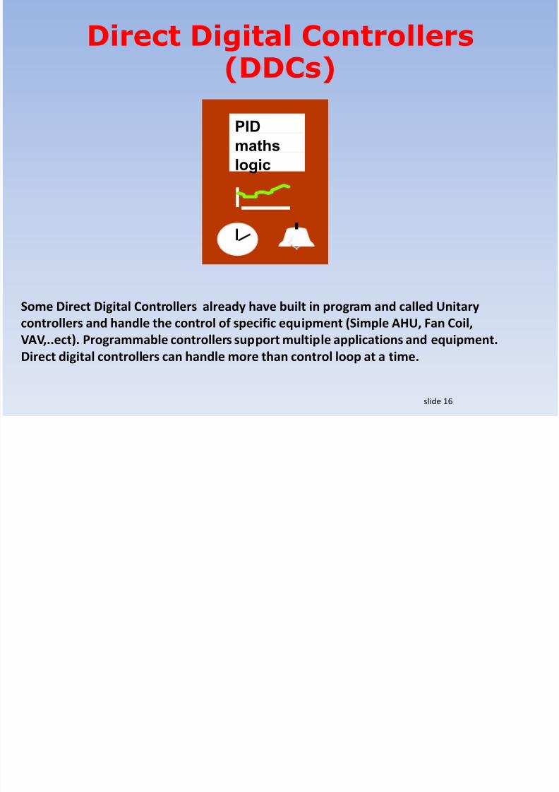
Direct Digital Controllers(DDCs)
Some Direct Digital Controllers already have built in program and called Unitary
controllers and handle the control of specific equipment (Simple AHU, Fan Coil,
VAV,..ect). Programmable controllers support multiple applications and equipment.
Direct digital controllers can handle more than control loop at a time.
slide 16
maths
logic
PID

8/10/2019 BMS.ppt
http://slidepdf.com/reader/full/bmsppt 17/70
Direct Digital Controllers(DDCs)
Graphical programming tool is usually used to program and configure DDC
controllers.
Each manufacturer implement the proper programming language for his own
product. slide 17
i i i l ll

8/10/2019 BMS.ppt
http://slidepdf.com/reader/full/bmsppt 18/70
Direct Digital ControllersInput/ Outputs
Different Type of inputs and outputs are connected to the DDC controller.
slide 18
Analogue
Temp
Pressure
Humidity
DigitalRunFault
Trip
Analogue
Modulated
DigitalOnOn
On/OffPulse
Meters
maths
logic
PID

8/10/2019 BMS.ppt
http://slidepdf.com/reader/full/bmsppt 19/70
Direct Digital ControllersInput/ Outputs Example
slide 19
Digital Inputs Examples:-Differential Pressure Switch is an example of Digital Input.
Usually installed across a fan or a filter. If the contact is
closed the DDC can detect either the fan is running or the
filter is clogged.
Smoke Detector installed in the duct to allow the controller
to stop the Air Handling Unit in case of Fire.
Auxiliary contact from contactor to indicate if the contactor is
energized or NOT.

8/10/2019 BMS.ppt
http://slidepdf.com/reader/full/bmsppt 20/70
Direct Digital ControllersInput/ Outputs Example
slide 20
Analog Inputs Example:-Temperature Sensors/ Setpoint Modules for Rooms.Temperature Sensors for Ducts.
Immersion temperature Sensors for water Pipes.
Humidity Transmitters for Rooms and Ducts.
Differential Pressure Transmitters for Clean
Rooms.
8/10/2019 BMS.ppt
http://slidepdf.com/reader/full/bmsppt 21/70
Direct Digital ControllersInput/ Outputs Example
slide 21
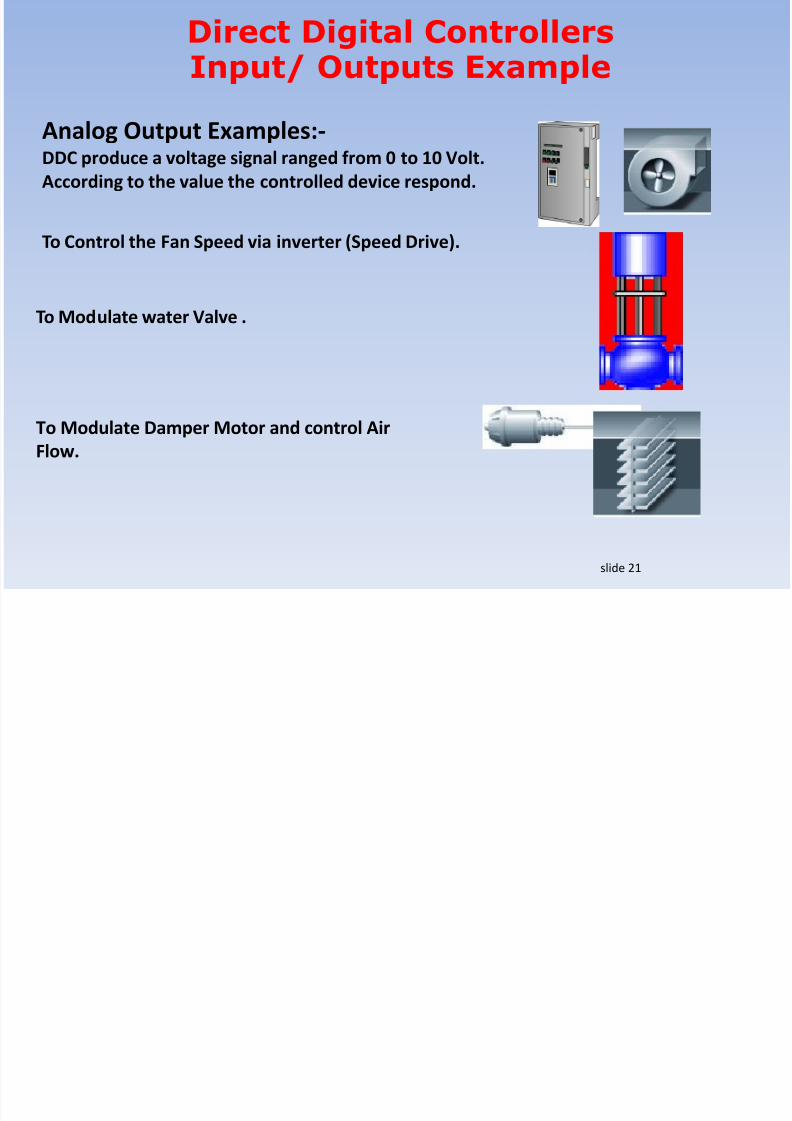
Analog Output Examples:-DDC produce a voltage signal ranged from 0 to 10 Volt.
According to the value the controlled device respond.
To Control the Fan Speed via inverter (Speed Drive).
To Modulate water Valve .
To Modulate Damper Motor and control Air
Flow.

8/10/2019 BMS.ppt
http://slidepdf.com/reader/full/bmsppt 22/70
Direct Digital ControllersInput/ Outputs Example
slide 22
Digital Output Examples:-Digital output is a relay output controlled by DDC
To Energize contactor in the motor control center in order to
start Fan or Pump.
To Start a condensing unit when using DX Air
Handling Units.
To energize Heater Battery Stages via
contactors
8/10/2019 BMS.ppt
http://slidepdf.com/reader/full/bmsppt 23/70
slide 23
DP
T
DP
T
DP
T
T
DP T
T
T
DP
boilers
DP
T
DP
T
DP
T
T
DP T
T
T
DP
chillers
FST T
T
air handling units
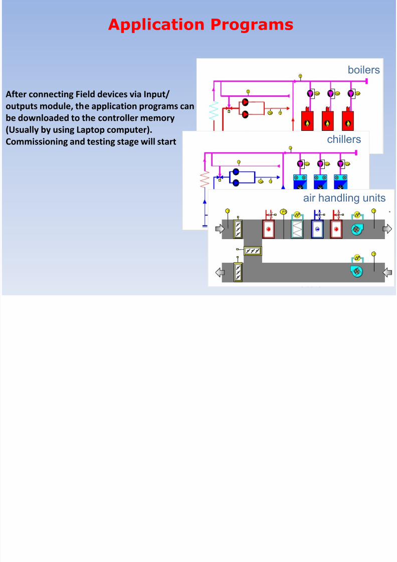
Application Programs
After connecting Field devices via Input/
outputs module, the application programs can
be downloaded to the controller memory
(Usually by using Laptop computer).
Commissioning and testing stage will start

8/10/2019 BMS.ppt
http://slidepdf.com/reader/full/bmsppt 24/70
slide 24
DP
T
DP
T
DP
T
T
DP T
T
T
DP
boilers
DP
T
DP
T
DP
T
T
DP T
T
T
DP
chillers
FST T
T
air handling units
Application Programs
After connecting Field devices via Input/
outputs module, the application programs can
be downloaded to the controller memory
(Usually by using Laptop computer).
Commissioning and testing stage will start

8/10/2019 BMS.ppt
http://slidepdf.com/reader/full/bmsppt 25/70
slide 25
Programming Tool
Programming Tool consists of mathematical and Boolean modules that
are connected to the inputs and outputs and also to each other in orderto produce the HVAC control Applications

8/10/2019 BMS.ppt
http://slidepdf.com/reader/full/bmsppt 26/70
slide 26
Application Program
After Finalizing the application program, It is tested off line and then
download to the controller.
8/10/2019 BMS.ppt
http://slidepdf.com/reader/full/bmsppt 27/70
slide 27
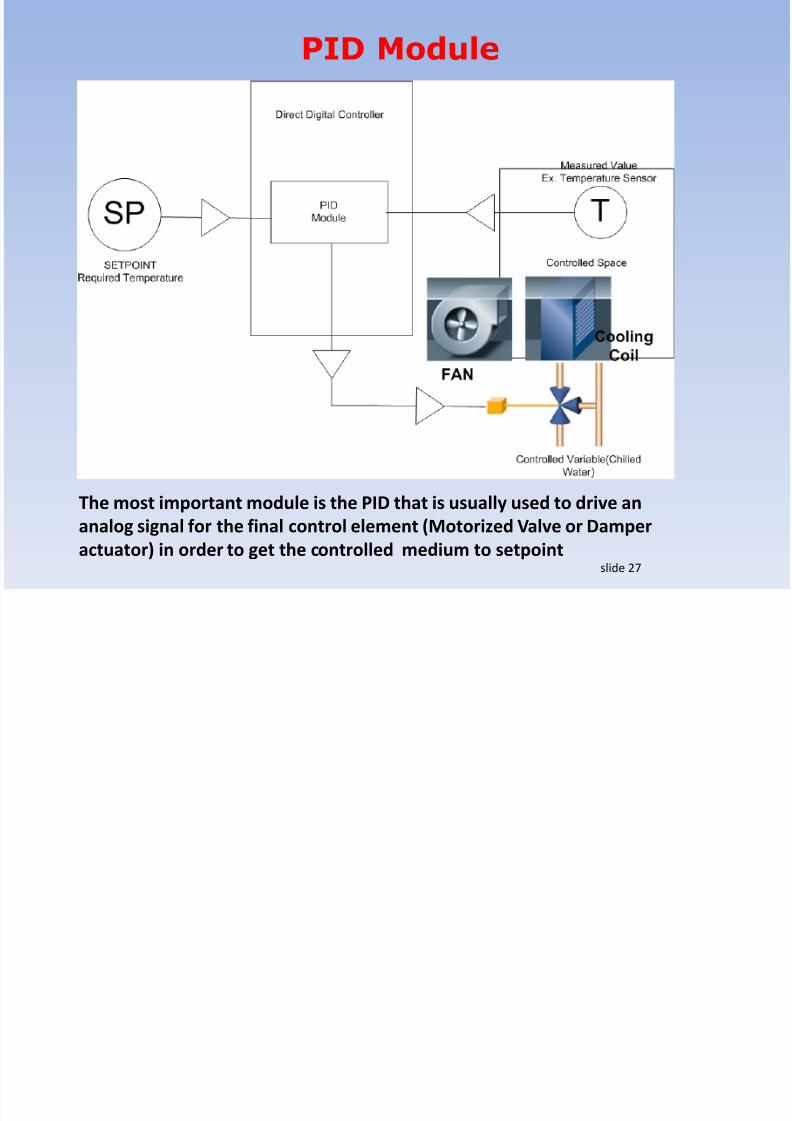
PID Module
The most important module is the PID that is usually used to drive an
analog signal for the final control element (Motorized Valve or Damper
actuator) in order to get the controlled medium to setpoint
8/10/2019 BMS.ppt
http://slidepdf.com/reader/full/bmsppt 28/70
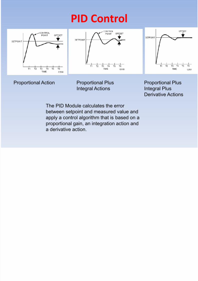
PID Control
The PID Module calculates the errorbetween setpoint and measured value and
apply a control algorithm that is based on a
proportional gain, an integration action and
a derivative action.
Proportional Action Proportional Plus
Integral Actions
Proportional Plus
Integral Plus
Derivative Actions

8/10/2019 BMS.ppt
http://slidepdf.com/reader/full/bmsppt 29/70
PID Control
With proportional control, the output is a function of thedeviation of the controlled variable from the setpoint. As
the control point stabilizes, offset occurs.
Proportional
Action
8/10/2019 BMS.ppt
http://slidepdf.com/reader/full/bmsppt 30/70
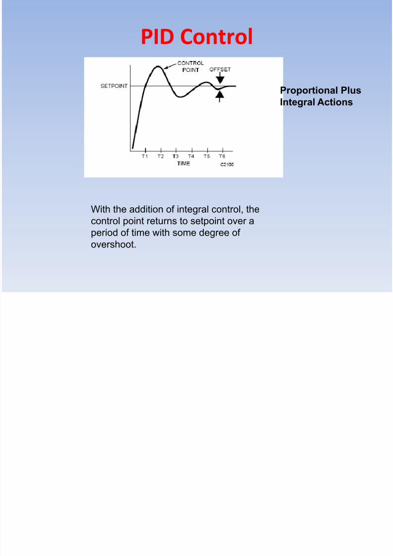
PID Control
With the addition of integral control, thecontrol point returns to setpoint over a
period of time with some degree of
overshoot.
Proportional Plus
Integral Actions

8/10/2019 BMS.ppt
http://slidepdf.com/reader/full/bmsppt 31/70
PID Control
The significant difference is the eliminationof offset after the system has stabilized.
The adding the derivative
element reduces overshoot and decreases
response time.
Proportional Plus
Integral Plus
Derivative Actions

8/10/2019 BMS.ppt
http://slidepdf.com/reader/full/bmsppt 32/70
Energy Management
Hemisphere)
Energy Management Programs are Built in the
Direct Digital Controllers memory and help in
saving power in case of the proper FieldDevices are installed.

8/10/2019 BMS.ppt
http://slidepdf.com/reader/full/bmsppt 33/70
Energy Management Comfort Costs
Energy Management is a compromise
between comfort and cost. It works between
the extreme boundaries of temperature and
RH.

8/10/2019 BMS.ppt
http://slidepdf.com/reader/full/bmsppt 34/70
Hemisphere)
• Night cycle
• Optimum Start/Stop
• Zero energy band
• Load reset
• Night cooling• Enthalpy control
• CO2 control
• Peak shaving
• Duty cycling• Presence detection
• Lighting control
Energy ManagementThe Most Applicable Energy Saving
Programs.

8/10/2019 BMS.ppt
http://slidepdf.com/reader/full/bmsppt 35/70
Optimum Start Stop with cooling
8/10/2019 BMS.ppt
http://slidepdf.com/reader/full/bmsppt 36/70
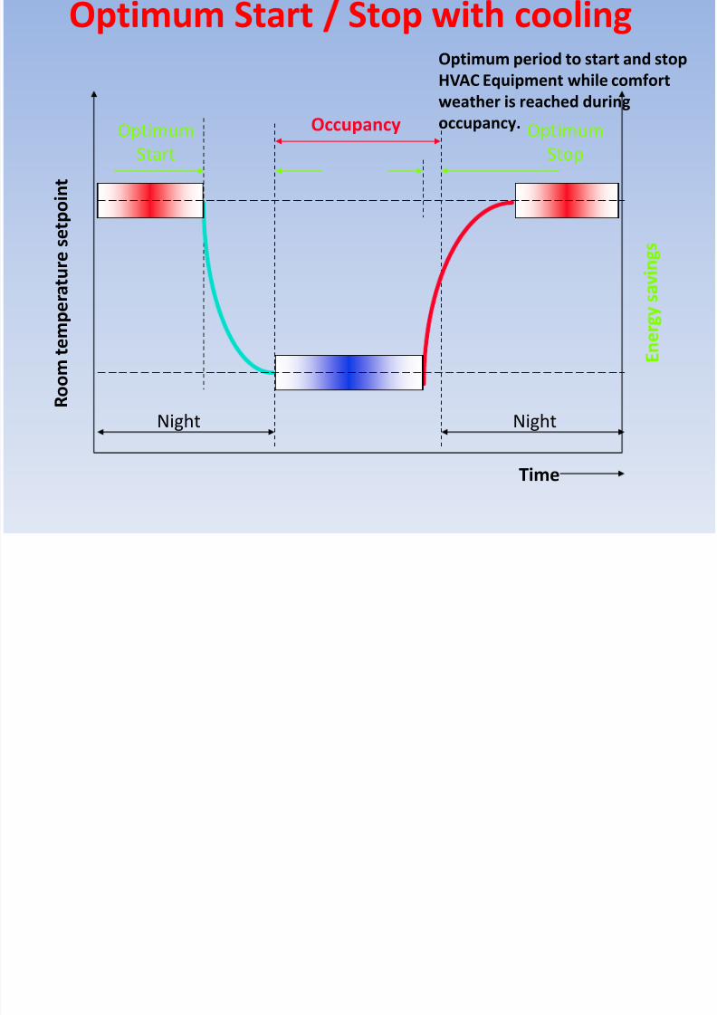
Optimum Start Stop with cooling Optimum period to start and stop
HVAC Equipment while comfort
weather is reached during
occupancy.OccupancyOptimumStart
OptimumStop
R o o
m t e
m p e r a t u r e
s e t p o i n t
NightNight
Time

8/10/2019 BMS.ppt
http://slidepdf.com/reader/full/bmsppt 37/70
Zero energy band
Night offset
Zero energy band
R o o m t e
m p e r a t u r e
Room temperaturesetpoint
When space temperature located
within comfort range, No cooling or
heating will be used.

8/10/2019 BMS.ppt
http://slidepdf.com/reader/full/bmsppt 38/70
Night cooling
Ti
RHi
Ta
RHa
If
Ta < Ti &
RHa < RHi
&Time between 04:00 and 08:00
Then
Night cooling
End

8/10/2019 BMS.ppt
http://slidepdf.com/reader/full/bmsppt 39/70
Enthalpy control
T
M
M
M
+
M
-
M M
RHT RH
T RH
Comparing outside and return
Enthalpy

8/10/2019 BMS.ppt
http://slidepdf.com/reader/full/bmsppt 40/70
CO2 control
+
M
xy
CO2
w
DSPL
Applicable when Electrical cost is

8/10/2019 BMS.ppt
http://slidepdf.com/reader/full/bmsppt 41/70
Time
E l e c t r i c a l
l o a d
Peak
limit
Schedded loads
higher at peak time

8/10/2019 BMS.ppt
http://slidepdf.com/reader/full/bmsppt 42/70
Presence detection
Night offset
Standby offset
Zero energy band
R o o m t e
m p e r a t u r e
Room temperaturesetpoint
Needs Occupancy Detector

8/10/2019 BMS.ppt
http://slidepdf.com/reader/full/bmsppt 43/70
Building Management System
Direct Digital Controller can work in
standalone bases. Readings can be
collected in the field by using
handheld operator terminal.

8/10/2019 BMS.ppt
http://slidepdf.com/reader/full/bmsppt 44/70
Building Management System
Co
%RH
T
°C Effective Setpoint
%%
°C°C
If the direct digital controllers are connected together and
to a central computer, then the building managementsystem is established.

8/10/2019 BMS.ppt
http://slidepdf.com/reader/full/bmsppt 45/70
Building Management System
The building management system software in
the computer does not perform any control
functions, as all the control routines are
executed in the DDCs.
The Building Management system function is
as follows:-.•Centralized the operation of the HVAC system
instead to pass by every machine to operate
and get the readings or change the setpoint
•Receive and record Alarms, Logs and reports.
•Low Level Integration with other systems.
•Graphic Display for equipment and readings.
S l f B ildi M t

8/10/2019 BMS.ppt
http://slidepdf.com/reader/full/bmsppt 46/70
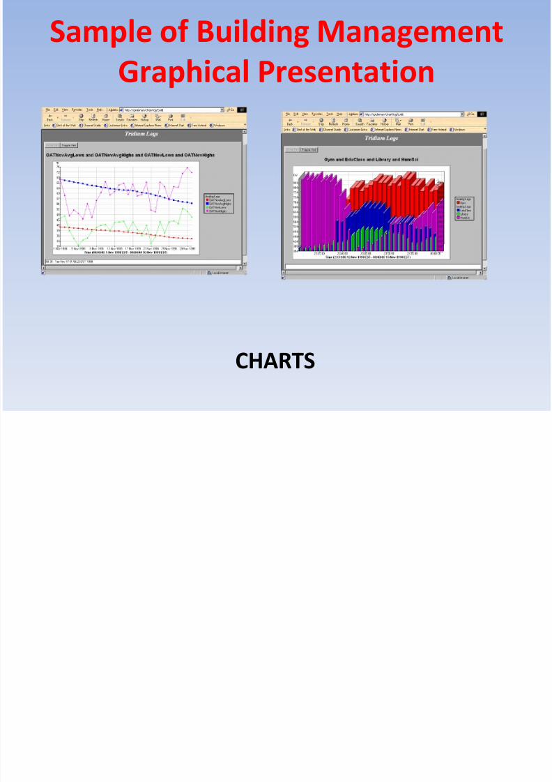
Sample of Building Management
Graphical Presentation
Air Handling Display
S l f B ildi M t

8/10/2019 BMS.ppt
http://slidepdf.com/reader/full/bmsppt 47/70
Sample of Building Management
Graphical Presentation
Chillier Plant Display
S l f B ildi M t
8/10/2019 BMS.ppt
http://slidepdf.com/reader/full/bmsppt 48/70
Sample of Building Management
Graphical Presentation
CHARTS
S l f B ildi M t

8/10/2019 BMS.ppt
http://slidepdf.com/reader/full/bmsppt 49/70
Sample of Building Management
Graphical Presentation
Alarm Logs
Language of Communication

8/10/2019 BMS.ppt
http://slidepdf.com/reader/full/bmsppt 50/70
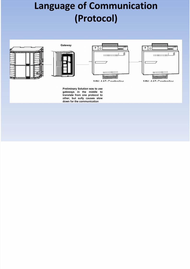
Language of Communication
(Protocol)
Language of Communication
8/10/2019 BMS.ppt
http://slidepdf.com/reader/full/bmsppt 51/70
Language of Communication
(Protocol)
8/10/2019 BMS.ppt
http://slidepdf.com/reader/full/bmsppt 52/70
Open Protocol
Years after, the implementation of a common
communication language “Protocol” started and
the most common protocols now are the Bacnet and
Lonworks.

8/10/2019 BMS.ppt
http://slidepdf.com/reader/full/bmsppt 53/70
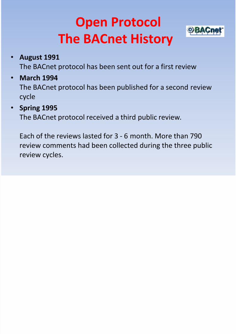
Open Protocol
The BACnet History
• 1987
The ASHRAE (American Society of Heating Refrigeration and
Air-Conditioning Engineering) Standard Project Committee SPC135P was founded. The committee was challenged to define a
communication protocol for building control and energy
management.
• January 1989 The ASHRAE journal publishes a first article about the idea of a
new protocol and the philosophy behind it.
8/10/2019 BMS.ppt
http://slidepdf.com/reader/full/bmsppt 54/70
Open Protocol
The BACnet History• August 1991
The BACnet protocol has been sent out for a first review
• March 1994
The BACnet protocol has been published for a second reviewcycle
• Spring 1995
The BACnet protocol received a third public review.
Each of the reviews lasted for 3 - 6 month. More than 790
review comments had been collected during the three public
review cycles.

8/10/2019 BMS.ppt
http://slidepdf.com/reader/full/bmsppt 55/70
Open Protocol
The BACnet History• September 1995
The ASHRAE Board of directors voted to ratify the BACnet
standard and published ASHRAE 135-1995.
• December 1995 BACnet was adopted by the ANSI (American National Standards
Institute) as the ASHRAE/ANSI Standard 135-1995.
• February 1996
BACnet debuted at the occasion of the International Air-Conditioning, Heating and Refrigerating Exposition.

8/10/2019 BMS.ppt
http://slidepdf.com/reader/full/bmsppt 56/70
Open Protocol
The BACnet History• Spring 1997
The CEN Technical Committee (TC) 247 Working Group (WG) 4
adopted and published BACnet as European Prenorm ENV
1805-1 (Management Level) andprENV 13321 (Automation Level).
In the meantime BACnet also had been ratified as
DIN V ENV 1805-1.
• December 1998
The ENV 13321 "Data communication for HVAC application:
automation net" became approved.

8/10/2019 BMS.ppt
http://slidepdf.com/reader/full/bmsppt 57/70
• BACnet is a communication protocol to exchange data
in Multi-Vendor Building Management
Systems/Networks
• It fits to the requirements of heating, cooling,
ventilation control but ...
• may also be the basis for integration of applications
like lighting, security and fire control
What’s BACnet good for?

8/10/2019 BMS.ppt
http://slidepdf.com/reader/full/bmsppt 58/70
What’s BACnet good for?
• The sophistication of a specific device, in terms of itsability to carry out particular service requests is
reflected by the device's conformance class.
– Each conformance class specifies a minimum set of services,
objects, and properties which the device must support inorder to claim membership in a particular class.
• The terms initiate and execute are used to describe a
device's capability to perform the application services
defined in the standard.
8/10/2019 BMS.ppt
http://slidepdf.com/reader/full/bmsppt 59/70
What’s BACnet good for?
• Functional groups: collections of BACnet standardobject types and application services that collectively
meet the communication requirements of a single
building function.
– The idea is to support specifiers as they specify specific
functionality like Event Initiation or Clock for particular
devices.
• BACnet is compliant to the OSI Communication
Model.There are various options for the physical and
the datalink layer.
What is the BTL?

8/10/2019 BMS.ppt
http://slidepdf.com/reader/full/bmsppt 60/70
What is the BTL?
BACnet Testing Laboratory was established by BACnet
International to support compliance testing and interoperability
testing activities.
General activities of the BTLThe general activities of the BTL are to publish an Implementation
Guidelines document for users of BACnet® with the help of the
working group, to organize and run the annual Interoperability
Workshop, and to test products for certification.

8/10/2019 BMS.ppt
http://slidepdf.com/reader/full/bmsppt 61/70
LONWORK BY
•Founded By Mike Markkula (Intel,Apple)
•Over 450 Products in product range
•Head Office: Palo Alto, California, USA.
•Over $100m and 500 man-years invested in bringingLONWORKS Technology to the market place

8/10/2019 BMS.ppt
http://slidepdf.com/reader/full/bmsppt 62/70
LONWORK BY
• Device Interoperability
• Intelligent Devices
• Standard Point Types (SNVT’s)
• Manufacturer Independent
• Open Communication Protocol (LNS)

8/10/2019 BMS.ppt
http://slidepdf.com/reader/full/bmsppt 63/70
Lonmark
• Independent Organisation
•The LonMark logo is an indication that a
product completed the LonMark conformance
tests and has been designed to interoperate across
an open multi-vendor LONWORKS control network
• More than 200 members

8/10/2019 BMS.ppt
http://slidepdf.com/reader/full/bmsppt 64/70
Neuron Chip• Most LonMark devices have this micro chip inside
• Designed by Echelon
• Made by Motorola, Toshiba & Cypress Semiconductor• Every chip has a unique 48 bit ID
• There are different Neuron chips for different uses
with the same design but different memory size, CPUspeed etc...
This keeps the price down for smaller devices but the
processing power for complex devices
8/10/2019 BMS.ppt
http://slidepdf.com/reader/full/bmsppt 65/70
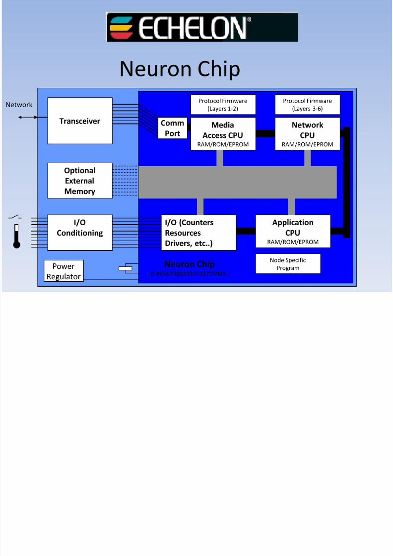
Neuron Chip
I/O (Counters
Resources
Drivers, etc..)
Application
CPURAM/ROM/EPROM
Media
Access CPURAM/ROM/EPROM
Network
CPURAM/ROM/EPROM
Protocol Firmware
(Layers 1-2)
Protocol Firmware
(Layers 3-6)
Transceiver
Optional
External
Memory
I/O
Conditioning
Power
Regulator
Node Specific
ProgramNeuron ChipID #65673882930482726987...
Network
Comm
Port

8/10/2019 BMS.ppt
http://slidepdf.com/reader/full/bmsppt 66/70
Neuron ID• Every device has a unique Neuron ID stored in the chip
at manufacture, this cannot be changed.
• When a device is commissioned the Neuron ID isrequired to make sure the correct device is programmed.
• There are Three methods of acquiring the Neuron ID
1. Manual Entry- Type the ID into the tool or Use a barcode reader.
2. Discovery- the network tool can discover unconfigured
devices
4. Service PIN- press the devices service pin
Protoco D erences on Pro ucts

8/10/2019 BMS.ppt
http://slidepdf.com/reader/full/bmsppt 67/70
and Services
LONBacnet
Future Trends

8/10/2019 BMS.ppt
http://slidepdf.com/reader/full/bmsppt 68/70
Future TrendsCustomer Expectations
• Reduction of initial investments
• Building Control System uses existing IT infrastructure
• A single user interface for all building disciplines (HVAC, Lighting, Lifts,Fire, …)
• Customers want supplier independence in case of later systemenhancement
• Reduction of operating, energy and maintenance costs
• Mobile operators want to operate the building at any time, fromeverywhere, immediately
• Less trained operator needs “intuitive" operating interfaces
• Central “Help Desk” serves many buildings in a geographical region
• Growing expectations for comfort and service
• Reduced energy consumption
Future Trends
8/10/2019 BMS.ppt
http://slidepdf.com/reader/full/bmsppt 69/70
Future TrendsCustomer Expectations
•Global connectivity
• Global companies need global BMSinformation
•Easy to operate
• Access at any time, from everywhere,immediately
• Use mainstream technology
• IT-world compliance
• Slim, inexpensive clients
Future Trends

8/10/2019 BMS.ppt
http://slidepdf.com/reader/full/bmsppt 70/70
Future TrendsCustomer Expectations


