1 Imperfection-sensitivity and catastrophe theory Zs. Gáspár BME Dept. of Structural Mechanics.

BME Department of Mechanics, Materials and Structures Special loadbearing structures 2018/2019 fall
T2. VIERENDEEL STRUCTURES AND FRAMES 1/11
T2. VIERENDEEL STRUCTURES
NOTE: The Picture Window House can be designed using a Vierendeel structure, but now we consider a
simpler problem to discuss the calculation algorithm of Vierendeel structures.
What’s the difference between a truss and a Vierendeel structure?
Truss Vierendeel structure
statically determinate statically indeterminate
can be calculated using statics there are too many unknowns in the equilibrium
equations we use an approximate method
all joints are pin joints, only normal and
shear force can be transmitted
fixed joints, capable of transferring bending
moments
the internal forces are either compressive or
tensile normal forces, no bending occurs
bending occurs in the members; normal force,
shear force and moment as internal forces.
Exercise 1. Vierendeel truss
Calculate the internal forces of the given Vierendeel structure!
Approximate method:
Hinges (pin-joints) are assumed at the mid-point of the rods (where 𝑀 ≈ 0), utilize symmetry and assume the
same stiffness for each members. These assumptions lead to a good approximation of the real behavior.
Step 1: Calculation of the reaction forces
The global statical model is a simply supported beam.
∑𝑀𝐴 = 0
550 ⋅ (2,5 + 5,0 + 7,5 + 10,0 + 12,5) +
+ 275 ⋅ 15,0 − 𝐵𝑦 ⋅ 15 = 0
→ 𝑩𝒚 = 𝟏𝟔𝟓𝟎 𝒌𝑵
∑𝐹𝑉 = 0
𝑨𝒚 = 𝐵𝑦 = 𝟏𝟔𝟓𝟎 𝒌𝑵
BME Department of Mechanics, Materials and Structures Special loadbearing structures 2018/2019 fall
T2. VIERENDEEL STRUCTURES AND FRAMES 2/11
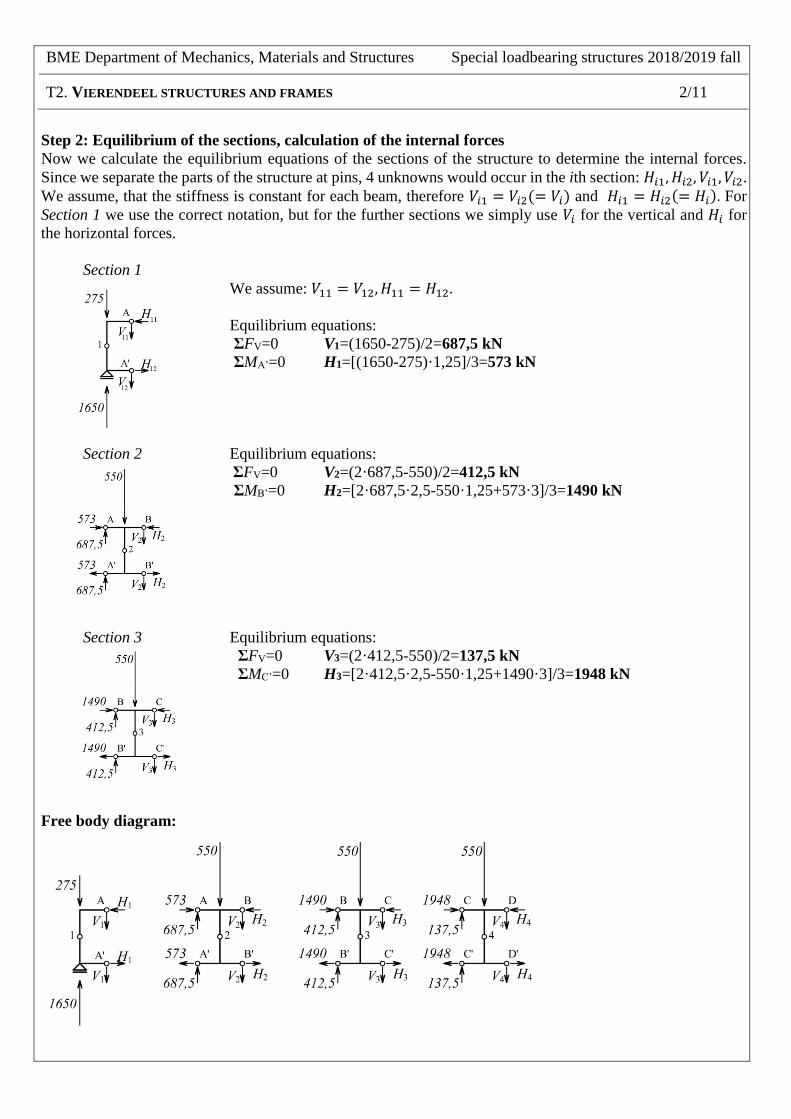
Step 2: Equilibrium of the sections, calculation of the internal forces
Now we calculate the equilibrium equations of the sections of the structure to determine the internal forces.
Since we separate the parts of the structure at pins, 4 unknowns would occur in the ith section: 𝐻𝑖1, 𝐻𝑖2, 𝑉𝑖1, 𝑉𝑖2.
We assume, that the stiffness is constant for each beam, therefore 𝑉𝑖1 = 𝑉𝑖2(= 𝑉𝑖) and 𝐻𝑖1 = 𝐻𝑖2(= 𝐻𝑖). For
Section 1 we use the correct notation, but for the further sections we simply use 𝑉𝑖 for the vertical and 𝐻𝑖 for
the horizontal forces.
Section 1
We assume: 𝑉11 = 𝑉12, 𝐻11 = 𝐻12.
Equilibrium equations:
ƩFV=0 V1=(1650-275)/2=687,5 kN
ƩMA’=0 H1=[(1650-275)·1,25]/3=573 kN
Section 2 Equilibrium equations:
ƩFV=0 V2=(2·687,5-550)/2=412,5 kN
ƩMB’=0 H2=[2·687,5·2,5-550·1,25+573·3]/3=1490 kN
Section 3 Equilibrium equations:
ƩFV=0 V3=(2·412,5-550)/2=137,5 kN
ƩMC’=0 H3=[2·412,5·2,5-550·1,25+1490·3]/3=1948 kN
Free body diagram:
BME Department of Mechanics, Materials and Structures Special loadbearing structures 2018/2019 fall
T2. VIERENDEEL STRUCTURES AND FRAMES 3/11
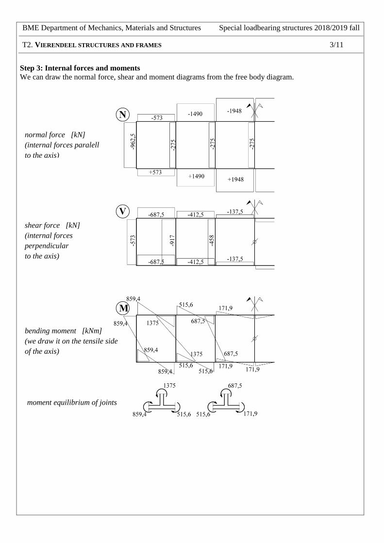
Step 3: Internal forces and moments
We can draw the normal force, shear and moment diagrams from the free body diagram.
normal force [kN]
(internal forces paralell
to the axis)
shear force [kN]
(internal forces
perpendicular
to the axis)
bending moment [kNm]
(we draw it on the tensile side
of the axis)
moment equilibrium of joints
BME Department of Mechanics, Materials and Structures Special loadbearing structures 2018/2019 fall
T2. VIERENDEEL STRUCTURES AND FRAMES 4/11
Step 4: Determine the maximal internal normal forces and moments
For designing the cross-section, we need the maximal internal normal forces and moments.
We have to identify the heavily loaded members. Method: mark the elements under either maximal normal
force or bending moment. In this problem, we can identify 4 members (meaning 4 different combinations of
N and M).
column:
1. Nmax= -962,5 kN; M = 859,4 kNm
2. N = -275 kN; Mmax = 1375 kNm
beam (chord):
3. Nmax= ± 1948 kN; M = 171,9 kNm
4. N = ± 573 kN; Mmax= 859,4 kNm
Step 5: Evaluation of the required cross section
We use the Dunkerley-formula:
0,1+Rd
Edyy
Rd
Ed
M
Mk
N
N (𝑘𝑦𝑦 ≈ 1 → interaction factor)
utilization of the cross section
𝑁𝐸𝑑 , 𝑀𝐸𝑑 are the normal force and moment from the effects (from Step 4)
𝑁𝑅𝑑 , 𝑀𝐸𝑑 are the resistances
The resistance of a cross section:
NRd ≈ χy,z ∙ A ∙ fyd (χy,z = 0,7 → buckling reduction factor)
MRd ≈ χLT ∙ Wpl ∙ fyd (χLT = 0,8 → lateral torsional buckling factor)
Try to find a proper cross-section! → cross section catalogue
We choose S235 material quality → fyd= 235 N/mm2
Let’s try cross-section HEB 700 (A=306,4 cm2, Wpl,y=8327 cm3) for the 2nd combination of Step 4!
NEd=-275 kN, MEd=1375 kNm
193,02351083278,0
101375
2351004,3067,0
102753
63
=
+
OK!
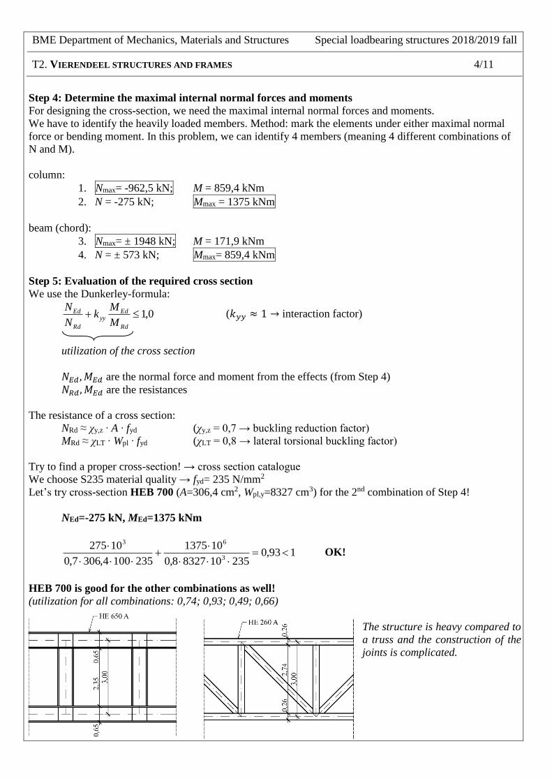
HEB 700 is good for the other combinations as well!
(utilization for all combinations: 0,74; 0,93; 0,49; 0,66)
The structure is heavy compared to
a truss and the construction of the
joints is complicated.

BME Department of Mechanics, Materials and Structures Special loadbearing structures 2018/2019 fall
T2. VIERENDEEL STRUCTURES AND FRAMES 5/11
T2. FRAMES
Most of our structures are under compression/tension and subjected to bending at the same time. Such
structures are: slabs, frames, beams and columns. Various loads increase the complexity of the calculation,
therefore we need an approximate method.
Portal-method
Frames are statically indeterminate with multiple degrees of indeterminacy. We simplify the calculation by
separating the vertical and horizontal loads.
Vertical loads:
Horizontal loads:
Approximate model: hinges are assumed at the middle of the columns. We utilize symmetry and assume that
the members have the same stiffness. The method results in a good approximation of the internal forces.
Vertical loads
Horizontal loads
The approximate method can be applied, if
- the spans are approximately equal
- the loads are constant and uniformly distributed
- the stiffness of the columns and the beams are around the same

BME Department of Mechanics, Materials and Structures Special loadbearing structures 2018/2019 fall
T2. VIERENDEEL STRUCTURES AND FRAMES 6/11
Exercise 2. Frames
Calculate the internal forces of one frame of a monolithic reinforced concrete (RC) framed office building
with the portal-method! Draw the N,V,M diagrams and sketch the deformation of the structure!
Additional information:
- frames are in every 6 m
- stiffness of the columns and beams are approximately the same
- the wind load can be approximated by a distributed load on one side* (due to the stiffness of
the slabs)
* otherwise the upwind and downwind sides must be handled separately
Steps:
1. free-body diagram, taking apart the frame
2. vertical and horizontal loads separately
3. specifying the bending moments
4. specifying the shear and normal forces
5. superposition of the N,V,M diagrams

BME Department of Mechanics, Materials and Structures Special loadbearing structures 2018/2019 fall
T2. VIERENDEEL STRUCTURES AND FRAMES 7/11
VERTICAL LOADS
Equilibrium of the stories:

BME Department of Mechanics, Materials and Structures Special loadbearing structures 2018/2019 fall
T2. VIERENDEEL STRUCTURES AND FRAMES 8/11
VERTICAL LOADS
Internal forces and moments
loads
support forces
deformation

BME Department of Mechanics, Materials and Structures Special loadbearing structures 2018/2019 fall
T2. VIERENDEEL STRUCTURES AND FRAMES 9/11
HORIZONTAL LOADS
Equilibrium of the stories:
𝑤 =1,2 ⋅ 6,0 ⋅ 6,0
2= 21,6𝑘𝑁

BME Department of Mechanics, Materials and Structures Special loadbearing structures 2018/2019 fall
T2. VIERENDEEL STRUCTURES AND FRAMES 10/11
HORIZONTAL LOADS
Internal forces and moments
loads
support forces
deformation

BME Department of Mechanics, Materials and Structures Special loadbearing structures 2018/2019 fall
T2. VIERENDEEL STRUCTURES AND FRAMES 11/11
HORIZONTAL AND VERTICAL LOADS
Internal forces and moments of the original structure (the rule of the superposition has been used)
loads
support forces