BLUETOOTH. What is Bluetooth? Goals Requirements Usage Models Bluetooth Architecture Security.
38
BLUETOOTH
-
Upload
jocelin-thornton -
Category
Documents
-
view
251 -
download
1
Transcript of BLUETOOTH. What is Bluetooth? Goals Requirements Usage Models Bluetooth Architecture Security.
BLUETOOTH
What is Bluetooth? Goals Requirements Usage Models Bluetooth Architecture Security
Bluetooth is a new standard developed by a group of electronics manufacturers that will allow any sort of electronic equipment -- from computers and cell phones to keyboards and headphones -- to make its own connections, without wires, cables or any direct action from a user.
A key difference with other existing wireless technologies is that bluetooth enables combined usability models based on functions provided by different devices.
The Bluetooth Special Interest Group comprises more than 1000 companies.The major companies who created the technology include Intel 3 com Ericcson IBM Motorola Nokia Toshiba
The Name –Bluetooth? The name is attributed to Harald Bluetooth
was king of Denmark around the turn of the last millennium.
Choosing this name for the standard indicates how important companies from the Baltic region (nations including Denmark, Sweden, Norway and Finland) are to the communications industry
Present wireless technology like infra red data communication has two problems –1)Line of Sight 2) One to One
Using data synchronizing– e.g. hot syn on a PDA --- problem of using the right cradle and cable.
BLUETOOTH OVERCOMES THESE PROBLEMS
It provides agreement at the physical level -- Bluetooth is a radio-frequency standard.
Provides agreement at the data link level where products have to agree on
when bits are sent how many will be sent at a time how the parties in a conversation can be sure that
the message received is the same as the message sent
The Basic Idea Bluetooth is a standard for a small ,
cheap radio chip to be plugged into computers, printers, mobile phones, etc
Bluetooth chip is designed to replace cables.Information normally carried by the cable, is transmitted at a special frequency to a receiver Bluetooth chip.
These devices can form a quick ad-hoc secure “piconet” and start communication.
Connections in the “piconets” can occur even when mobile.
“Piconet” A collection of devices connected via
Bluetooth technology in an ad hoc fashion. A piconet starts with two connected
devices, and may grow to eight connected devices.
All Bluetooth devices are peer units and have identical implementations. However, when establishing a piconet, one unit will act as a Master and the other(s) as slave(s) for the duration of the piconet connection.
Requirements Low cost as cables – chip $5 Secure as cables – must support authentication
and encryption Must support both data and voice. Must connect to a variety of devices. Must be able to function in a noisy environment. Data rates – 721kbps , using the 2.45Ghz radio
frequency band –I.S.M (Industrial, scientific and medical)
Must support many simultaneous and private “piconets”.
Must be low power, compact and global.
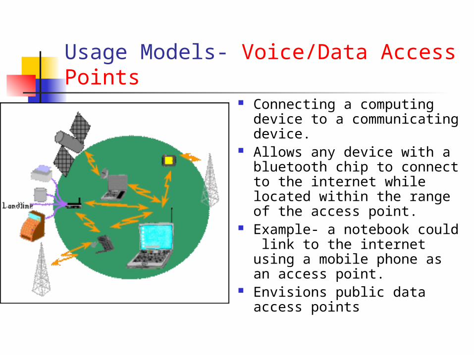
Usage Models- Voice/Data Access Points
Connecting a computing device to a communicating device.
Allows any device with a bluetooth chip to connect to the internet while located within the range of the access point.
Example- a notebook could link to the internet using a mobile phone as an access point.
Envisions public data access points
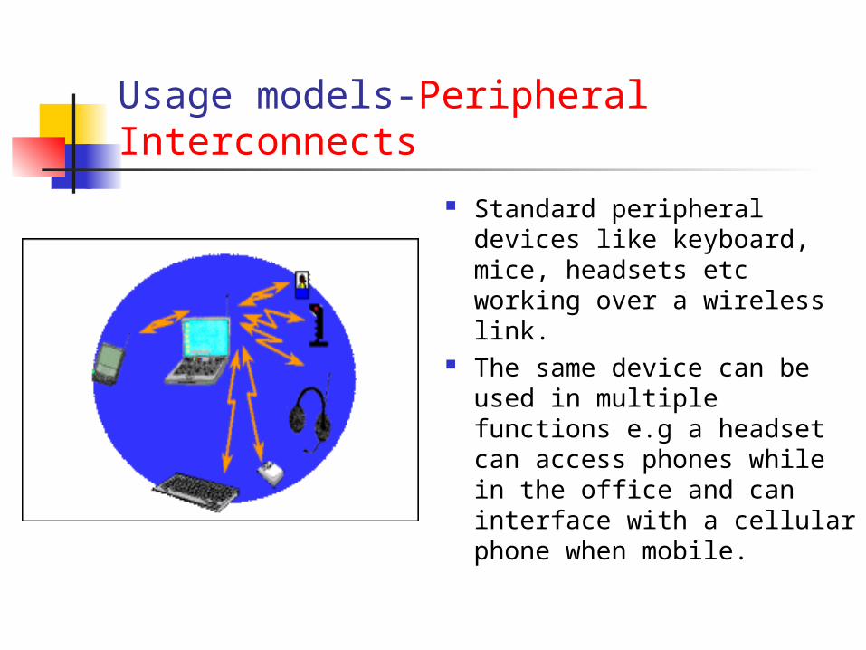
Usage models-Peripheral Interconnects
Standard peripheral devices like keyboard, mice, headsets etc working over a wireless link.
The same device can be used in multiple functions e.g a headset can access phones while in the office and can interface with a cellular phone when mobile.
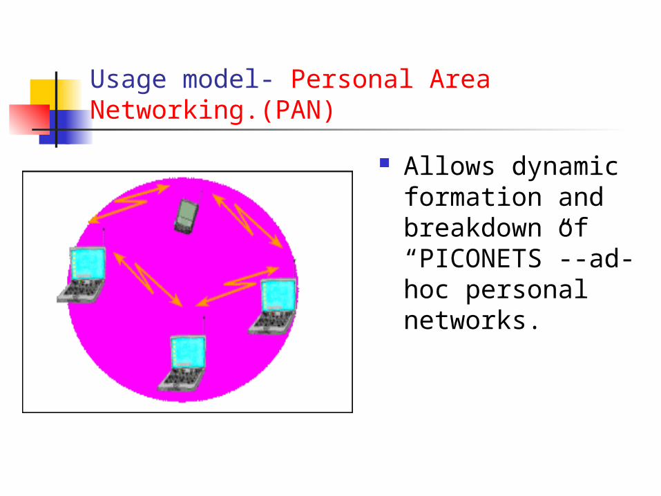
Usage model- Personal Area Networking.(PAN)
Allows dynamic formation and breakdown of “PICONETS”--ad-hoc personal networks.
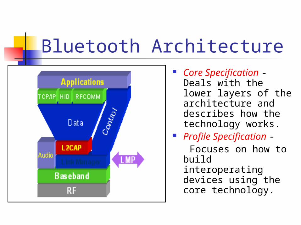
Bluetooth Architecture Core Specification -
Deals with the lower layers of the architecture and describes how the technology works.
Profile Specification - Focuses on how to
build interoperating devices using the core technology.
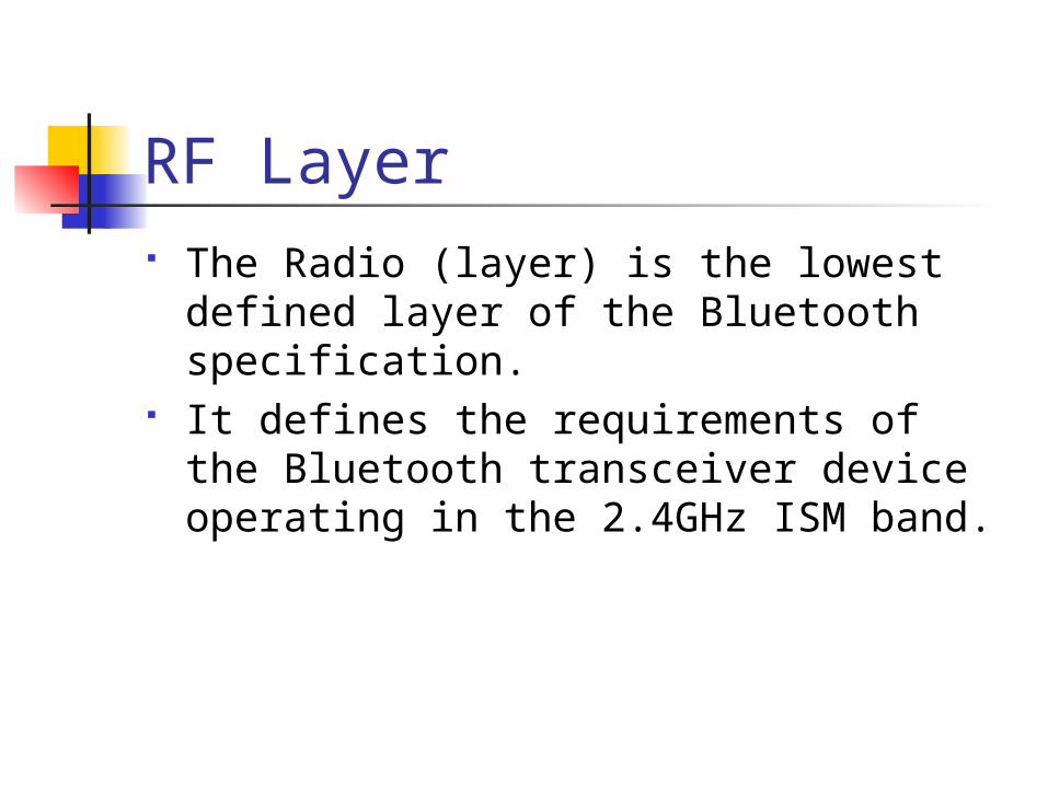
RF Layer The Radio (layer) is the lowest defined
layer of the Bluetooth specification. It defines the requirements of the
Bluetooth transceiver device operating in the 2.4GHz ISM band.
In order to minimize interference the nominal antenna power is 1 mW which can be extended to 100mW.
The low power limits the range to about 10 centimeters to 10 meters. With higher power of 100mW range of 100meters can be achieved.
It uses a packet switching protocol based on a technology called spread-spectrum frequency hopping to spread the energy across the ISM band.
Spread-Spectrum frequency hopping
A device will use 79 individual randomly chosen frequencies within a designated range, changing from one to another on a regular basis.
The designated range is from 2.402GHz to 2.480GHz, in steps of 1MHz.
The frequency hopping is done at a rate of 1600 times a second.
This allows more devices to use the limited time slice and secondly reduces the chance of two transmitters being on the same frequency at the same time.

Baseband layer – This layer defines the timing, framing, packets and flow control on the link.
Link Manager – Responsible for managing connection states(authentication & encryption), enforcing fairness among slaves & power mangt.
Logical Link Layer – Handles multiplexing, segmentation and reassembly of large packets and device discovery.
Audio – The audio data is directly mapped to the baseband layer.
Bluetooth Frame Each frame consists of a transmit
packet and a receive packet. Each packet may have either 1, 3 or 5
slots of 625ùs. Single slot packet – max data rate of
172Kbps Multislot frames support higher rates–
721Kbps or a max. of 3 voice channels.
Network Topology All units have a unique global
ID(BD_Addr) address( 48 bits) The unit that initializes the connection is
assigned as the master which controls the traffic of the connection.
A master can simultaneously connect upto seven slaves.
The master/slave roles can be swapped. A device can be a master in only one
“piconet” at a time.
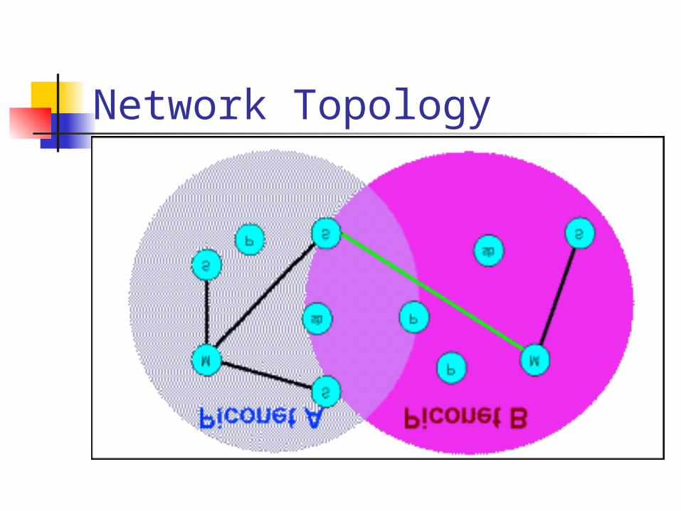
Network Topology
Forming a piconet Needs two parameters --- a) Hopping
pattern of the radio it wishes to connect. b) Phase within the pattern i.e. the clock offset of the hops.
The global ID defines the hopping pattern. The master shares its global ID and its clock
offset with the other radios which become slaves.
The global ID and the clock parameters are exchanged using a FHS (Frequency Hoping Synchronization) packet.
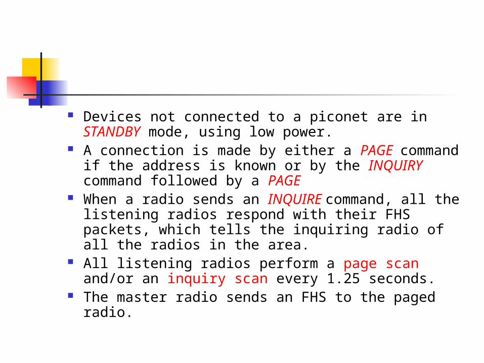
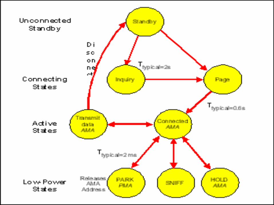
Devices not connected to a piconet are in STANDBY mode, using low power.
A connection is made by either a PAGE command if the address is known or by the INQUIRY command followed by a PAGE
When a radio sends an INQUIRE command, all the listening radios respond with their FHS packets, which tells the inquiring radio of all the radios in the area.
All listening radios perform a page scan and/or an inquiry scan every 1.25 seconds.
The master radio sends an FHS to the paged radio.
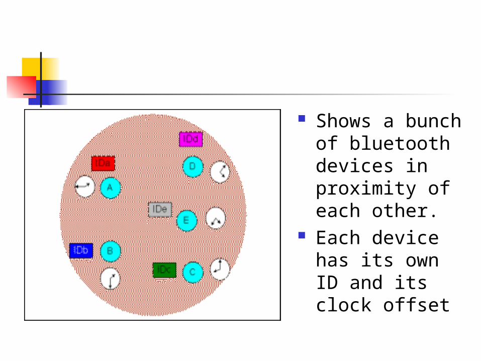
Shows a bunch of bluetooth devices in proximity of each other.
Each device has its own ID and its clock offset
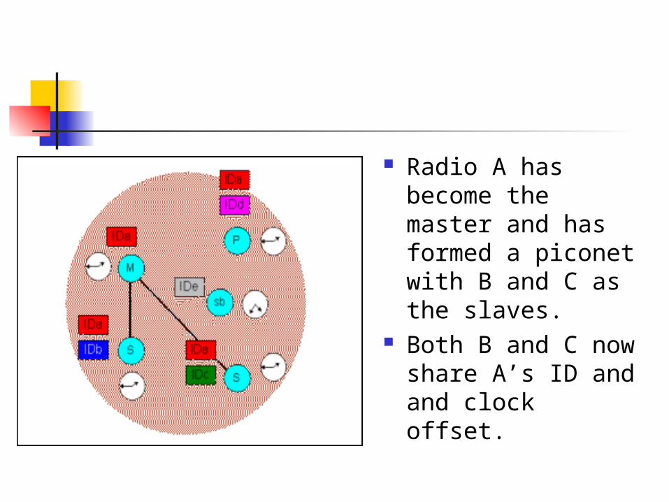
Radio A has become the master and has formed a piconet with B and C as the slaves.
Both B and C now share A’s ID and and clock offset.
When a radio joins a piconet it is assigned a 3 bit Active Member Address(AMA).
Once the piconet has eight radios, the master assigns puts a radio into the PARK mode.
This is one of the low power states, in which the radio releases its AMA for a 8 bit PMA (Passive Member Address).
The freed AMA can be assigned to another radio wishing to join the piconet.
Though upto 256 radios can actively reside on a piconet, only 8 of them with AMA’s can transfer data.
Inquiry Scan One radio performs a page function on a
special Inquiry ID global address. Listening radios perform an inquiry scan on
a unique sequence of 32 channels. The radio will listen every 1.25 seconds on
each of these 32 channels for 10ms and will then repeat the same for the next channel.
The inquiring radio issues a number of pages on the inquire channels and then listens for a response for 1.25 seconds for 16 of the 32 channels.
If a listening radio was doing a page scan on one of these inquire channels it will respond with its FHS packet.
The sequence is repeated for the second set of 16 channels.
After an inquire scan is performed the inquiring radio will have a list of all the FHS packets of all the radios within its range.
Page Scan A page scan is done by a radio in the Standby
mode if the address of the device to connect is known.
Each radio has a unique sequence of 32 paging frequencies and 32 response frequencies based on its Global ID.
The radio will listen for a page of its global ID on each of the 32 paging frequency for 10ms, changing frequency every 1.25 seconds.
The paging radio will continuously page using the paged radio’s Global ID on one of the set of 16 paging frequency for 1.25seconds.
The paging radio estimates the 16 frequencies on which to start paging based on the last known clock offset.
If the paging radio receives no response then it will page on the remaining 16 frequencies for the next 1.25 seconds.
Connecting time Clock offset Clock offset how recently were they were connected.
Once a radio joins the piconet and has an AMA it can direct data to other devices on the piconet.
In order to remain in the connected state within a piconet, the radio needs to maintain the frequency hopping pattern and offset while consuming low power.
To achieve this the connected radios can be placed in either PARK, HOLD or SNIFF modes.
HOLD MODE When data needs to be transmitted very
infrequently, thus conserving power. In this mode only an internal timer is running. No data is transferred when in HOLD mode. The master can put slaves on HOLD mode.SNIFF MODE A slave device listens to the piconet at a reduced
rate. The SNIFF interval is programmable. In both the HOLD and SNIFF states the device
retains its AMA.
PARK MODE The device has given up the AMA
and has become passive. The parked device will occasionally
listen to see if the master has sent any broadcast data asking it to become active.
Types of Links and Packets
Synchronous Connection Oriented(SCO) Point to point full duplex link. Typically used for voice data. These packets do not use CRC and
are not retransmitted. Needs an asynchronous
connectionless (ACL) type link to be first established.
Asynchronous Connectionless Link This is a packet switched link
between a master and slave. Supports both isochronous and
asynchronous data.Error Correction Schemes Forward error correction(1/3 and 2/3) Automatic Repeat Request scheme.
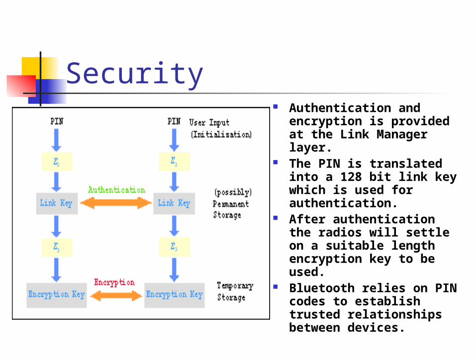
Security Authentication and
encryption is provided at the Link Manager layer.
The PIN is translated into a 128 bit link key which is used for authentication.
After authentication the radios will settle on a suitable length encryption key to be used.
Bluetooth relies on PIN codes to establish trusted relationships between devices.
References Bluetooth Architecture Overview James Kardach www.bluetooth.com www.palowireless.com