Blue Sea
144
pages 6-27 page 42 Terminal Fuse Block and Fuse Mounts on 3/8" (M10) battery post, battery switch, and busbar terminals • Interrupt Rating satisfies ABYC requirements for DC Main circuit protection on large battery banks • Ignition protected—safe for installation aboard gasoline powered boats • Clear window—visual indication of blown condition • Color coded for each amperage page 50 Available Fall, 2007 Residual Current Circuit Breaker (RCBO) Provides Main or Branch circuit protection • Ground fault protection of a GFCI combined with the overcurrent trip characteristics of a circuit breaker • Trips on short circuit, overload, or leakage to ground • Front panel mount—installed in power distribution panel • Available in rocker or toggle styles pages 20-21 Available Fall, 2007 • Combines battery banks during charging and isolates under discharge • 300 Ampere continuous rating suitable for use with large battery banks, starters, alternators, and inverter/chargers • Can be remotely combined with optional switch Available Spring, 2008 Available Fall, 2007 1 3110 3102 5191 (fuse not included) ML-Series Solenoid Switches (Magnetic Latch) Provides high-current remote battery switching • 300 Ampere continuous rating for use as a remote battery switch for inboard gasoline or diesel engines, reducing long cable runs • Magnetic latch only draws current when changing state of switch, drawing no current in “ON” or “OFF” state • Silver alloy contacts provides high reliability for switching live loads page 39 Available Spring, 2008 NEW PRODUCTS 2008 Flexibility—the unique open frame architecture allows for future changes to the panel which can change with the way you use your boat. The 360 Panel System—a new approach to power distribution panels Working with our worldwide customer base of boat builders and electrical suppliers over the years, we have developed a new panel system that meets both the visual and functional demands of the most discerning boater. Broadest Range of Functionality—a modular approach allows the combining of functions including flat rocker or toggle magnetic circuit breakers, push button reset-only thermal circuit breakers, meters, gauges and battery switches to be installed in the same panel. Advanced Design Features—easy to change backlit labels, hidden mounting screws and circuit breakers that meet the latest ABYC requirements are just some of the features you can expect. Fast Shipment—custom panels can be designed and shipped in days not weeks. Custom panels are available for boat manufactures and through a select group of distributors. Specifications subject to change. See www.bluesea.com for current information. Catalog 2008 ML-Series Automatic Charging Relay (Magnetic Latch) Combines large battery banks for high current charging and emergency cross connect 7700 7620
-
Upload
brendanc55323 -
Category
Documents
-
view
50 -
download
3
description
electrical equipment
Transcript of Blue Sea

pages 6-27
page 42
Terminal Fuse Block and Fuse Mounts on 3/8" (M10) battery post, battery switch, and busbar terminals• Interrupt Rating satisfi es ABYC requirements for DC Main circuit protection on
large battery banks
• Ignition protected—safe for installation aboard gasoline powered boats
• Clear window—visual indication of blown condition
• Color coded for each amperage
page 50 Available Fall, 2007
Residual Current Circuit Breaker (RCBO)
Provides Main or Branch circuit protection • Ground fault protection of a GFCI combined with the overcurrent trip
characteristics of a circuit breaker
• Trips on short circuit, overload, or leakage to ground
• Front panel mount—installed in power distribution panel
• Available in rocker or toggle styles
pages 20-21 Available Fall, 2007
• Combines battery banks during charging and isolates under discharge
• 300 Ampere continuous rating suitable for use with large battery banks, starters,
alternators, and inverter/chargers
• Can be remotely combined with optional switch
Available Spring, 2008
Available Fall, 2007
1
3110 3102
5191 (fuse not included)
ML-Series Solenoid Switches(Magnetic Latch)Provides high-current remote battery switching • 300 Ampere continuous rating for use as a remote battery switch for inboard gasoline
or diesel engines, reducing long cable runs
• Magnetic latch only draws current when changing state of switch, drawing no current in
“ON” or “OFF” state
• Silver alloy contacts provides high reliability for switching live loads
page 39 Available Spring, 2008
NEW PRODUCTS 2008
Flexibility—the unique open frame architecture allows for future changes to the
panel which can change with the way you use your boat.
The 360 Panel System—a new approach to power distribution panels
Working with our worldwide customer base of boat builders and electrical suppliers over the years, we have developed a new panel system that meets both the visual and functional demands of the most discerning boater.
Broadest Range of Functionality—a modular approach allows the combining of
functions including fl at rocker or toggle magnetic circuit breakers, push button
reset-only thermal circuit breakers, meters, gauges and battery switches to
be installed in the same panel.
Advanced Design Features—easy to change backlit labels, hidden mounting
screws and circuit breakers that meet the latest ABYC requirements are just some
of the features you can expect.
Fast Shipment—custom panels can be designed and shipped in days not weeks.
Custom panels are available for boat manufactures and through a select group
of distributors.
Specifi cations subject to change. See www.bluesea.com for current information. Catalog 2008
ML-Series Automatic Charging Relay(Magnetic Latch)Combines large battery banks for high current charging and emergency cross connect
7700
7620

2
DC 360 Panel System 10–16
AC 360 Panel System 17–21
Combination AC/DC 360 Panel System 22
Meters, Gauges, and Panels 23–25
Accessories 26–27
PRODUCTS BY APPLICATIONDC MAIN BATTERY MANAGEMENT 28–43
Battery Switches 30–35
Battery Management Panels 36–37
Solenoid Switches 38–39
Automatic Charging Relays (ACRs) 40–43
DC MAIN CIRCUIT PROTECTION 44–53
Circuit Breakers 46–49
Fuse Blocks 50–53
Fuses 50–53
DC BRANCH POWER DISTRIBUTION AND CIRCUIT PROTECTION 54–65
ABOVE DECK—Waterproof Panels 56–59
BELOW DECK—Toggle Circuit Breaker Panels 60–61
Circuit Breakers 62
Fuse Blocks 63–65
Fuses 65
AC MAIN POWER DISTRIBUTION AND CIRCUIT PROTECTION 66–73
Circuit Breakers and Mounting Panels 70–73
120/240 Volt C-Series Toggle Circuit Breaker Panels 73
A-Series Main Toggle Circuit Breaker Panels 68–69
AC MAIN SOURCE SELECTION 74–81
A-Series Source Selection Toggle Circuit Breaker Panels 76–77
120/240 Volt C-Series Source Selection Toggle Circuit Breaker Panels 78
Rotary Switches and Rotary Source Selection Panels 79–81
AC BRANCH POWER DISTRIBUTION AND CIRCUIT PROTECTION 82–87
Circuit Breakers 86–87
A-Series Toggle Circuit Breaker Panels 84–85
AC/DC COMBINATION PANELS AND CIRCUIT PROTECTION 88–91
A-Series Main Toggle Circuit Breaker Panels 90–91
A-Series Source Selection Toggle Circuit Breaker Panels 90–91
ACCESSORIES 92–103
Waterproof Panel Accessories 94–95
Panel Accessories and Digital Dimmers 96–99
12 Volt Socket-Plug System 97
Labels 100–103
METERING AND ACCESSORIES 104–113
Digital Meters 106–107
Analog DIN Meters 108–109
Analog Meters 110–111
Meter Panels, Mini Clamp Multimeter, and Accessories 112–113
BUSBARS, CONNECTORS, AND INSULATORS 114–125
BusBars 116–120
Terminal Blocks and Jumpers 120–122
Feed Through Connectors 122
PowerPosts 123
CableClams/CableCaps 124–125
APPENDIX, TECHNICAL GLOSSARY, AND INDEX 126–144
360 PANEL SYSTEM 6–27
DC 360 Panel System 10–16
AC 360 Panel System 17–21
Combination AC/DC 360 Panel System 22
Meters, Gauges, and Panels 23–25
Accessories 26–27
AUTOMATIC CHARGING RELAYS 28–29, 40–43
BATTERY SWITCHES 28–35, 40
BUSBARS 114–120
CIRCUIT BREAKERS
AC Rocker Single Pole 87
AC Rocker Double Pole 71, 73
AC Rocker Triple Pole 73
AC Toggle Single Pole 86, 87
AC Toggle Double Pole 70, 72
AC Toggle Triple Pole 72
DC Rocker Single Pole 49, 62
DC Rocker Double Pole 49
DC Rocker Triple Pole 49
DC Toggle Single Pole 48, 62
DC Toggle Double Pole 48
DC Toggle Triple Pole 48
Push Button Thermal 46
CONNECTORS
BusBars 114–120
Cable Connectors 123
Feed Through Connectors 122
PowerPosts 123
Terminal Blocks and Jumpers 120–122
FUSE BLOCKS
Fuse Blocks 50–53, 63–65
FUSES
Fuses 50–53, 65
INSULATORS
CableCaps 125
CableClams 124
METERS
Accessories 112–113
Analog DIN 108–109
Analog 110–111
Digital 106–107
Digital Dimmers 99
Mini Clamp Multimeter 112
Meter Panels 112
DISTRIBUTION PANELS
AC 120/240 Volt 78
AC Branch 84–85
AC Main 68–69, 73
AC Source Selector 76–81
Accessories and Labels 92–103
Combination AC/DC 90–91
DC Battery Management 36–37
DC Branch 60–61
Waterproof Circuit Breaker 56–57, 59
Waterproof Fuse 58–59
SWITCHES
Battery 28–35,40
Panel 96
Rotary 79–81
Solenoid 38-39
Water Resistant Contura 95
WeatherDeck™ Toggle Single Pole 94
WeatherDeck™ Toggle Double Pole 94
PRODUCTS BY CATEGORY 360 PANEL SYSTEM 6–27
Blue Sea Systems

BUSBARS, CONNECTORS, AND INSULATORS
METERING AND ACCESSORIES
ACCESSORIES
AC/DC COMBINATION PANELS AND CIRCUIT PROTECTION
AC BRANCH POWER DISTRIBUTION AND CIRCUIT PROTECTION
3
AC MAIN SOURCE SELECTION
AC MAIN POWER DISTRIBUTION AND CIRCUIT PROTECTION
DC BRANCH POWER DISTRIBUTION AND CIRCUIT PROTECTION
DC MAIN CIRCUIT PROTECTION
DC MAIN BATTERY MANAGEMENT
360 PANEL SYSTEM
Catalog 2008
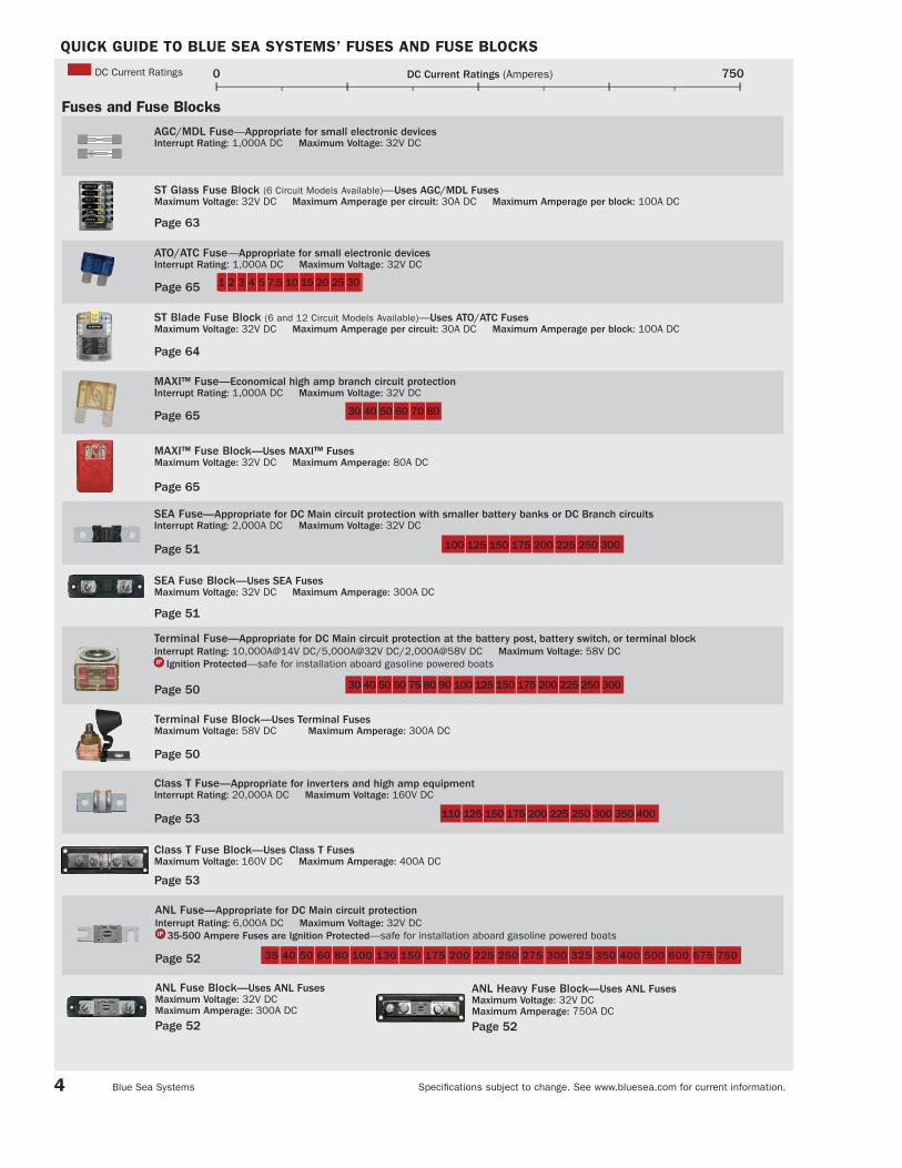
QUICK GUIDE TO BLUE SEA SYSTEMS’ FUSES AND FUSE BLOCKS
4
Fuses and Fuse Blocks
ST Glass Fuse Block (6 Circuit Models Available)—Uses AGC/MDL FusesMaximum Voltage: 32V DC Maximum Amperage per circuit: 30A DC Maximum Amperage per block: 100A DC
Page 63
AGC/MDL Fuse—Appropriate for small electronic devicesInterrupt Rating: 1,000A DC Maximum Voltage: 32V DC
MAXI™ Fuse—Economical high amp branch circuit protection Interrupt Rating: 1,000A DC Maximum Voltage: 32V DC
MAXI™ Fuse Block—Uses MAXI™ FusesMaximum Voltage: 32V DC Maximum Amperage: 80A DC
Page 65
Page 65
30 40 50 60 70 80
SEA Fuse—Appropriate for DC Main circuit protection with smaller battery banks or DC Branch circuitsInterrupt Rating: 2,000A DC Maximum Voltage: 32V DC
SEA Fuse Block—Uses SEA FusesMaximum Voltage: 32V DC Maximum Amperage: 300A DC
Page 51
Page 51
100 125 150 175 200 225 250 300
Class T Fuse Block—Uses Class T FusesMaximum Voltage: 160V DC Maximum Amperage: 400A DC
Page 53
Class T Fuse—Appropriate for inverters and high amp equipmentInterrupt Rating: 20,000A DC Maximum Voltage: 160V DC
110 125 150 175 200 225 250 300 350 400Page 53
ST Blade Fuse Block (6 and 12 Circuit Models Available)—Uses ATO/ATC FusesMaximum Voltage: 32V DC Maximum Amperage per circuit: 30A DC Maximum Amperage per block: 100A DC
Page 65
Page 64
ATO/ATC Fuse—Appropriate for small electronic devicesInterrupt Rating: 1,000A DC Maximum Voltage: 32V DC
1 2 3 4 5 7.5 10 15 20 25 30
Page 52
ANL Fuse Block—Uses ANL FusesMaximum Voltage: 32V DC Maximum Amperage: 300A DC
Page 52
ANL Heavy Fuse Block—Uses ANL FusesMaximum Voltage: 32V DC Maximum Amperage: 750A DC
Page 52
35 40 50 60 80 100 130 150 175 200 225 250 275 300 325 350 400 500 600 675 750
ANL Fuse—Appropriate for DC Main circuit protectionInterrupt Rating: 6,000A DC Maximum Voltage: 32V DC
35-500 Ampere Fuses are Ignition Protected—safe for installation aboard gasoline powered boats
Terminal Fuse—Appropriate for DC Main circuit protection at the battery post, battery switch, or terminal block Interrupt Rating: 10,000A@14V DC/5,000A@32V DC/2,000A@58V DC Maximum Voltage: 58V DC
Ignition Protected—safe for installation aboard gasoline powered boats
Terminal Fuse Block—Uses Terminal FusesMaximum Voltage: 58V DC Maximum Amperage: 300A DC
Page 50
Page 50
30 40 50 60 75 80 90 100 125 150 175 200 225 250 300
750DC Current Ratings (Amperes)0DC Current Ratings
Specifi cations subject to change. See www.bluesea.com for current information. Blue Sea Systems

187-Series—Appropriate for DC Main circuit protection with battery banks over 1,000 CCA in adverse environmentsInterrupt Rating: 5,000A@12V DC / 3,000A@24V DC/1,500A@42 DC Maximum Voltage: 48V DC
Ignition Protected—safe for installation aboard gasoline powered boats
QUICK GUIDE TO BLUE SEA SYSTEMS’ CIRCUIT BREAKERS
5
Thermal Circuit Breakers
185-Series—Appropriate for DC Main circuit protection with battery banks under 1,000 CCA in adverse environmentsInterrupt Rating: 3,000A DC Maximum Voltage: 42V DC Ignition Protected—safe for installation aboard gasoline powered boats
Magnetic Hydraulic Circuit Breakers
A-Series Toggle, 1 Pole—Appropriate for AC and DC Branch circuit protectionInterrupt Rating: 7,500A@65V DC/3,000A@250V AC Maximum Voltage: 65V DC/250V AC
A-Series Toggle, 2 Pole—Appropriate for 120V AC Main or 240V AC Branch circuit protectionInterrupt Rating: 3,000A AC Maximum Voltage: 250V AC
A-Series Flat and Restricted OFF Rocker, 1 Pole—Appropriate for AC and DC Branch and 24-hour circuit protectionInterrupt Rating: 5,000A@32V DC/3,000A@125V AC/1,500A@240V AC Maximum Voltage: 32V DC/240V AC
A-Series Flat and Raised Rocker, 2 Pole—Appropriate for 120V AC Main or 240V AC Branch circuit protectionInterrupt Rating: 3,000A AC Maximum Voltage: 240V AC
C-Series Toggle, 1 Pole—Appropriate for DC Main and AC and DC heavy load circuit protectionInterrupt Rating: 10,000A AC Maximum Voltage: 80V DC/240V AC
100 Ampere Circuit Breaker is Ignition Protected—safe for installation aboard gasoline powered boats
C-Series Toggle, 2 and 3 Pole—Appropriate for DC heavy load circuit protectionInterrupt Rating: 5,000A@65V DC Maximum Voltage: 65V DC
C-Series Toggle, 2 and 3 Pole—Appropriate for 240V AC Main and AC heavy load circuit protectionInterrupt Rating: 5,000A@250V AC Maximum Voltage: 250V AC
C-Series Flat Rocker, 1 Pole—Appropriate for DC Main and AC and DC heavy load circuit protectionInterrupt Rating: 5,000A@32V DC/3,000A@125V AC Maximum Voltage: 32V DC/240V AC
Ignition Protected—safe for installation aboard gasoline powered boats
C-Series Flat Rocker, 2 and 3 Pole—Appropriate for DC heavy load circuit protectionInterrupt Rating: 5,000A@48V DC Maximum Voltage: 48V DC
C-Series Flat and Raised Rocker, 2 and 3 Pole—Appropriate for 240V AC Main and AC heavy load circuit protectionInterrupt Rating: 5,000A AC Maximum Voltage: 240V AC
3 4 5 7 10 12 15 20 25 30 35 40
5 8 10 15 20 25 30 40 50
25 30 35 40 50 60 70 80 90 100 110 120 135 150
25 30 35 40 50 60 70 80 90 100 110 120 135 150
10 15 16 20 30 32 40 50
5 8 10 15 20 25 30 40 50
10 15 16 20 30 32 40 50
150* 175* 200* 250† 300†
30* 50‡ 60‡ 80‡ 100‡
5 1 0 1 5 2 0 2 5 3 0 5 0 6 0 8 0 1 0 0
5 1 0 1 5 2 0 2 5 3 0 5 0 6 0 8 0 1 0 0
* Available in 2 Pole / † Available in 3 Pole / ‡ Available in 2 and 3 Pole
Page 46
Page 46
Page 47
Page 62, 86
Page 70
Page 62, 87
Page 71
Page 48, 87
Page 48
Page 72
Page 49
Page 49
Page 73
Push Button Reset-Only—Appropriate for 24-hour circuit protectionInterrupt Rating: 3,[email protected] DC/2,500A@28V DC Ignition Protected—safe for installation aboard gasoline powered boats
150* 175* 200* 250† 300†
30* 50‡ 60‡ 80‡ 100‡
RCBO Circuit Breaker Toggle and Rocker, 1 and 2 Pole—Appropriate for ground fault and overcurrent trip protectionInterrupt Rating: 5,000A AC Maximum Voltage: 240V AC
1 5 1 6 3 0Page 21
300AC and DC Current Ratings (Amperes)0AC Current Ratings
DC Current Ratings
Specifi cations subject to change. See www.bluesea.com for current information. Catalog 2008

360 PANEL SYSTEM INTRODUCTION
Specifi cations subject to change. See www.bluesea.com for current information. Blue Sea Systems 6
Flexibility—the unique open frame architecture allows for future changes to the panel which can change with the way you use your boat.
The 360 Panel System—a new approach to power distribution panelsWorking with our worldwide customer base of boat builders and electrical suppliers over the years, we have developed a new panel system that meets both the visual and functional demands of the most discerning boater.
Broadest Range of Functionality—a modular approach allows the combining of functions including fl at rocker or toggle magnetic circuit breakers, push button reset-only thermal circuit breakers, meters, gauges and battery switches to be installed in the same panel.
Advanced Design Features—easy to change backlit labels, hidden mounting screws and circuit breakers that meet the latest ABYC requirements are just some of the features you can expect.
Fast Shipment—custom panels can be designed and shipped in days not weeks. Custom panels are available for boat manufacturers and through a select group of distributors.

360 PANEL SYSTEM INTRODUCTION
Specifi cations subject to change. See www.bluesea.com for current information. Catalog 2008 7
Broadest Range of Functionality
m-Series Battery Switches
• ON/OFF, Selector, Dual Circuit™,
and Dual Circuit Plus™ enable
sophisticated battery management
systems to be integrated into the
360 Distribution Panel
Rocker Style Circuit Breakers
• Modern styling, resistance to
accidental switching and
restricted switching models
Toggle Style Circuit Breakers
• For a traditional look and feel
DC 12 Volt Sockets*
• Twin 12 Volt receptacles
integrated into the 360
Distribution Panel
Systems Monitor*
Available Spring 2008• Monitor volts, amperes, watts,
frequency, DC ampere-hours
• Monitor tanks and bilge condition
• Alarms for all measured values
AC and DC Digital Meters
• Monitor volts, amperes, watts,
frequency
• DC voltage alarms, AC voltage
and amperage alarms
AC and DC90°Analog DIN Meters*
• Monitor volts and amperes
AC and DC60°Analog Meters
• Monitor volts and amperes
2" Round GaugesDC Push Button Reset-Only Circuit Breakers
• Circuit protection only for
un-switched 24 hour circuits
or switches at other locations
• Monitor engine, tanks, electrical,
clock and hour meter values
DC Battery Management*
DC Push Button Reset-Only Circuit Breakers with Rocker Switches
• Economical switched circuit
protection for circuits less than
8 amperes
Available Spring 2008• Control and graphic
connection state information
for Blue Sea Systems solenoids
and ACRs
AC Multiple Source Rotary Switch-Type Management
• Safe management of multiple
AC sources with a fully backlight
Rotary Switch AC Management
System
Blank Panel*
• Platform for a variety of controls
and instruments that can be
mounted into the 360
Distribution Panel for an
integrated appearance
AC Multiple Source Slide Management for Rocker-Style Circuit Breakers
• Safe management of multiple
AC sources for Rocker-Style
Circuit Breakers
AC Multiple Source Slide Management for Toggle-Style Circuit Breakers
• Safe management of multiple
AC sources for Toggle-Style
Circuit Breakers
* Available in custom panels only
360 PANEL SYSTEM INTRODUCTION
Specifi cations subject to change. See www.bluesea.com for current information. Blue Sea Systems 8
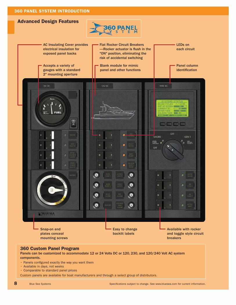
360 Custom Panel Program Panels can be customized to accommodate 12 or 24 Volts DC or 120, 230, and 120/240 Volt AC system components.
Panels confi gured exactly the way you want them•
Available in days, not weeks•
Comparable to standard panel prices•
Custom panels are available for boat manufacturers and through a select group of distributors.
Advanced Design Features
Snap-on endplates concealmounting screws
Easy to changebacklit labels
LEDs oneach circuit
Accepts a variety of gauges with a standard 2" mounting aperture
Panel column identifi cation
Available with rocker and toggle style circuit breakers
AC Insulating Cover provides electrical insulation for exposed panel backs
Blank module for mimic panel and other functions
Flat Rocker Circuit Breakers—Rocker actuator is fl ush in the "ON" position, eliminating the risk of accidental switching

360 PANEL SYSTEM SECTION INDEX
Specifi cations subject to change. See www.bluesea.com for current information. Catalog 2008 9
Battery Management Panels
Push Button Reset-Only Circuit Breaker and Push Button Reset-Only Circuit Breaker + Rocker Switch Panels
DC Branch Circuit Breaker Panels with Hydraulic/Magnetic Circuit Breakers
DC Main Battery Management and Power Distribution Panels Pages 10–16
Page 10–11
Page 12–13
Page 14–16
Gauges and Gauge Panels Pages 24–25
Gauges
Page 24
AC Main Source Selection and Power Distribution Pages 17–21
Rotary Switch Source Selection Panels
A-Series Circuit Breaker Source Selection Panels
AC Magnetic Circuit Breaker Panels with Hydraulic/Magnetic Circuit Breakers
Residual Current Circuit Breaker (RCBO) and Residual Current Circuit Breaker (RCBO) Panels
Page 18
Page 19
Page 17
Pages 20–21
AC/DC Combination Panels Pages 22–23
120 and 230 Volt AC/12 Volt DC Black Toggle Circuit Breaker Panels
120 and 230 Volt AC/12 Volt DC Rocker Circuit Breaker Panels
Page 22
Page 22
Meter Panels Pages 23
DC Analog Voltmeter and DC Digital Voltmeter Panels
Page 23
360 Panel System Accessories Pages 26–27
12 to 24 Volt Conversion Kit
AC Panel Insulating Covers
Rocker Switches
Page 26
Page 26
Page 27
Gauge Panels
Page 25

360 PANEL SYSTEM
Specifi cations subject to change. See www.bluesea.com for current information. Blue Sea Systems 10
PN DescriptionWidth
in" (mm)Height
in" (mm)
Installed Flat Rocker Circuit Breaker
Installed Push Button Circuit Breaker
InstalledRocker Switch100A Main 15A 10A 15A
1400 DC M-Series ON/OFF + 8 Pos CLB V¹ 4.875 (123.83) 7.750 (196.85) - - - 8 -
1401 DC M-Series ON/OFF + 4 Pos Switch CLB V¹ 4.875 (123.83) 7.750 (196.85) - - 4 - 4
1402 DC M-Series ON/OFF + Main 3 Pos CLB V¹ 4.875 (123.83) 7.750 (196.85) 1 - - 3 -
1403 DC M-Series ON/OFF + Main 3 Pos FR V¹ 4.875 (123.83) 7.750 (196.85) 1 3 - - -
PN Description Width in" (mm) Height in" (mm)
Installed Flat Rocker Circuit Breaker
15A
1406 DC 3 M-Series ON/OFF H² 13.625 (346.08) 4.750 (120.65) -
1407 DC 3 M-Series ON/OFF V¹ 4.875 (123.83) 10.750 (273.05) -
PN Description Width in" (mm) Height in" (mm)
Installed Flat Rocker Circuit Breaker
100A Main 15A
1404 DC 2 M-Series ON/OFF + 4 Pos FR H² 13.625 (346.08) 4.750 (120.65) 1 3
1405 DC 2 M-Series ON/OFF + 4 Pos FR V¹ 4.875 (123.83) 10.750 (273.05) 1 3
Dual Battery,Single Engine
ENGINE HOUSE
ENG
1404
1405
Single Battery, Single Engine
ENGINE
ENG
1402 1403
1406
1407
NEW PRODUCT
1400 1401
Dual Battery,Single Engine
ENGINE HOUSE
ENG
¹ Vertical / ² Horizontal
DC Single Battery -Series ON/OFF Battery Switch Panels with Branch Circuit ProtectionDesigned for single battery single engine confi gurations
• Incorporates an -Series ON/OFF Battery Switch 6006200 (pages 30–31)
• Includes 4218—Square Format Label Set (pages 100–101)
• 1400/1402: Push Button Reset-Only Branch circuit breakers provide economical
high-density circuit protection when switching is provided elsewhere
—ideal for 24-hour circuit protection
• 1402/1403: Provides DC Main circuit protection
• 1401/1402/1403: Provides circuit switching
Specifi cations
-Series Battery Switch 6006200 Ratings Pages 30–31
Nominal Voltage 12 Volts DC
m
m
m
DC Dual Battery -Series ON/OFF Battery Switch PanelsDesigned for dual battery single engine confi gurations
• Incorporates -Series ON/OFF Battery Switches 6006200 (pages 30–31)
• Isolates the Engine circuit from the House circuit
• Protects electronics from sags and spikes caused by engine cranking
• Allows independent battery discharge
• Addition of an automatic charging relay automates charging of both batteries (pages 40–43)
• Includes 4218—Square Format Label Set (pages 100–101)
• Enables a failed House or Start battery bank to be isolated from the electrical system and
both House and Start loads to be operated from the remaining battery bank
Specifi cations
-Series Battery Switch 6006200 Ratings Pages 30–31
Nominal Voltage 12 Volts DC
m
m
m
DC Dual Battery -Series ON/OFF Battery Switch Panels with Branch Circuit ProtectionDesigned for dual battery single engine confi gurations
• Incorporates -Series ON/OFF Battery Switches 6006200 (pages 30–31)
• Isolates the Engine circuit from the House circuit
• Protects electronics from sags and spikes caused by engine cranking
• Allows independent battery discharge
• Addition of an automatic charging relay automates charging of both batteries (pages 40–43)
• Includes 4218—Square Format Label Set (pages 100–101)
• Flat rocker Branch circuit breakers eliminate the risk of accidental switching
Specifi cations
-Series Battery Switch 6006200 Ratings Pages 30–31
Nominal Voltage 12 Volts DC
m
m
m
360 PANEL SYSTEM
Specifi cations subject to change. See www.bluesea.com for current information. Catalog 2008 11
PN DescriptionWidth
in" (mm)Height
in" (mm)
Installed C-SeriesFlat Rocker
Circuit Breaker
InstalledPush Button
Circuit Breaker
InstalledRocker
Switches100A Main 15A 10A 15A
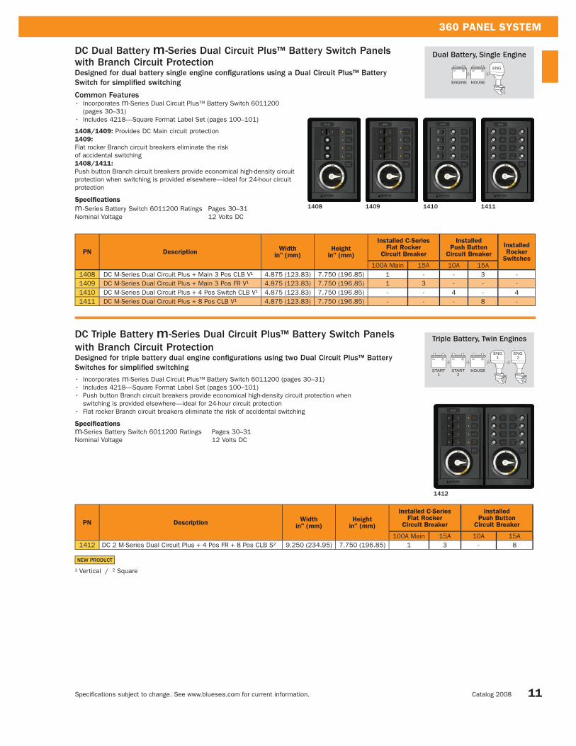
1408 DC M-Series Dual Circuit Plus + Main 3 Pos CLB V¹ 4.875 (123.83) 7.750 (196.85) 1 - - 3 -
1409 DC M-Series Dual Circuit Plus + Main 3 Pos FR V¹ 4.875 (123.83) 7.750 (196.85) 1 3 - - -
1410 DC M-Series Dual Circuit Plus + 4 Pos Switch CLB V¹ 4.875 (123.83) 7.750 (196.85) - - 4 - 4
1411 DC M-Series Dual Circuit Plus + 8 Pos CLB V¹ 4.875 (123.83) 7.750 (196.85) - - - 8 -
1408 1409 1410 1411
1412
Triple Battery, Twin Engines
START1
START2
HOUSE
ENG1
ENG2
Dual Battery, Single Engine
ENGINE HOUSE
ENG
PN DescriptionWidth
in" (mm)Height
in" (mm)
Installed C-SeriesFlat Rocker
Circuit Breaker
InstalledPush Button
Circuit Breaker
100A Main 15A 10A 15A
1412 DC 2 M-Series Dual Circuit Plus + 4 Pos FR + 8 Pos CLB S² 9.250 (234.95) 7.750 (196.85) 1 3 - 8
NEW PRODUCT
¹ Vertical / ² Square
DC Triple Battery -Series Dual Circuit Plus™ Battery Switch Panelswith Branch Circuit ProtectionDesigned for triple battery dual engine confi gurations using two Dual Circuit Plus™ Battery Switches for simplifi ed switching
• Incorporates -Series Dual Circuit Plus™ Battery Switch 6011200 (pages 30–31)
• Includes 4218—Square Format Label Set (pages 100–101)
• Push button Branch circuit breakers provide economical high-density circuit protection when
switching is provided elsewhere—ideal for 24-hour circuit protection
• Flat rocker Branch circuit breakers eliminate the risk of accidental switching
Specifications
-Series Battery Switch 6011200 Ratings Pages 30–31
Nominal Voltage 12 Volts DC
m
m
m
DC Dual Battery -Series Dual Circuit Plus™ Battery Switch Panelswith Branch Circuit ProtectionDesigned for dual battery single engine confi gurations using a Dual Circuit Plus™ Battery Switch for simplifi ed switching
Common Features• Incorporates -Series Dual Circuit Plus™ Battery Switch 6011200
(pages 30–31)
• Includes 4218—Square Format Label Set (pages 100–101)
1408/1409: Provides DC Main circuit protection
1409:
Flat rocker Branch circuit breakers eliminate the risk
of accidental switching
1408/1411:
Push button Branch circuit breakers provide economical high-density circuit
protection when switching is provided elsewhere—ideal for 24-hour circuit
protection
Specifications
m -Series Battery Switch 6011200 Ratings Pages 30–31
Nominal Voltage 12 Volts DC
m
m

360 PANEL SYSTEM
Specifi cations subject to change. See www.bluesea.com for current information. Blue Sea Systems 12
DC Push Button Reset-Only Branch Circuit Breaker PanelsDesigned as an economical solution for circuits that remain "ON" or are switched elsewhere
• High-density circuit protection
• Includes 4205—Square Format Label Set (pages 100–101)
8 Position CLB S
1450
16 Position CLB V
1452
8 PositionSwitch CLB V
1457
4 Position SwitchCLB + Meter V
1459
12 Position Switch CLB V
1461
8 Position Switch CLB + Meter V
1463
8 Position Switch CLB H
1456
4 PositionSwitch CLB S
1455
8 Position Switch CLB + Meter H
1462
12 Position Switch CLB H
1460
4 Position Switch CLB + Meter H
1458
16 Position CLB H
1451
24 Position CLB H
1453
24 Position CLB V
1454
PN Description Width in" (mm) Height in" (mm)Installed Push Button Circuit Breakers
15A1450 8 Position CLB S¹ 4.875 (123.83) 4.750 (120.65) 8
1451 16 Position CLB H² 9.250 (234.95) 4.750 (120.65) 16
1452 16 Position CLB V³ 4.875 (123.83) 7.750 (196.85) 16
1453 24 Position CLB H² 13.625 (346.08) 4.750 (120.65) 24
1454 24 Position CLB V³ 4.875 (123.83) 10.750 (273.05) 24
DC Push Button Reset-Only Circuit Breakers and Rocker Switch PanelsDesigned as an economical solution for circuits requiring both circuit protection and switching
• Available with voltmeters and ammeters
• Includes 4205—Square Format Label Set (pages 100–101)
NEW PRODUCT
See page 27 for fullselection of RockerSwitches
¹ Square / ² Horizontal / ³ Vertical

360 PANEL SYSTEM
Specifi cations subject to change. See www.bluesea.com for current information. Catalog 2008 13
PN DescriptionMeter Type
Meter PNMeterPages
Width in" (mm) Height in" (mm)
InstalledPush Button
Circuit Breakers
InstalledRocker
Switches10A
1455 4 Position Switch CLB S¹ - - - 4.875 (123.83) 4.750 (120.65) 4 4
1458 4 Position Switch CLB + Meter H² Voltmeter 8003 110 9.250 (234.95) 4.750 (120.65) 4 4
1459 4 Position Switch CLB + Meter V³ Voltmeter 8003 110 4.875 (123.83) 7.750 (196.85) 4 4
1456 8 Position Switch CLB H² - - - 9.250 (234.95) 4.750 (120.65) 8 8
1457 8 Position Switch CLB V³ - - - 4.875 (123.83) 7.750 (196.85) 8 8
1462 8 Position Switch CLB + Meter H² Voltmeter 8003 110 13.625 (346.08) 4.750 (120.65) 8 8
1463 8 Position Switch CLB + Meter V³ Voltmeter 8003 110 4.875 (123.83) 10.750 (273.05) 8 8
1460 12 Position Switch CLB H² - - - 13.625 (346.08) 4.750 (120.65) 12 12
1461 12 Position Switch CLB V³ - - - 4.875 (123.83) 10.750 (273.05) 12 12
1464 12 Position Switch CLB + Meter S¹ Voltmeter 8003 110 9.250 (234.95) 7.750 (196.85) 12 12
1465 16 Position Switch CLB S¹ - - - 9.250 (234.95) 7.750 (196.85) 16 16
1466 16 Position Switch CLB + Meters H² Volt/Amp 8003/8022 110 13.625 (346.08) 7.750 (196.85) 16 16
1467 16 Position Switch CLB + Meters V³ Volt/Amp 8003/8022 110 9.250 (234.83) 10.750 (273.05) 16 16
1470 20 Position Switch CLB + Meter H² Voltmeter 8003 110 13.625 (346.08) 7.750 (196.85) 20 20
1471 20 Position Switch CLB + Meter V³ Voltmeter 8003 110 9.250 (234.95) 10.750 (273.05) 20 20
1468 24 Position Switch CLB H² - - - 13.625 (346.08) 7.750 (196.85) 24 24
1469 24 Position Switch CLB V³ - - - 9.250 (234.83) 10.750 (273.05) 24 24
24 Position Switch CLB V
1469
20 Position Switch CLB Meter V
1471
16 Position Switch CLB + Meters H
1466
12 Position Switch CLB + Meter S
1464
16 Position Switch CLB + Meters V
1467
24 Position Switch CLB H
1468
16 Position Switch CLB S
1465
20 Position Switch CLB + Meter H
1470
NEW PRODUCT ¹ Square / ² Horizontal / ³ Vertical

360 PANEL SYSTEM
Specifi cations subject to change. See www.bluesea.com for current information. Blue Sea Systems 14
DC Branch Circuit Breaker Panels with Hydraulic/Magnetic Circuit BreakersDesigned for circuits requiring both circuit protection and switching
Common Features• 4 to 32 branch circuits with installed 15 Ampere circuit breakers
• Available with voltmeters, ammeters, and digital multimeters
• Includes 4205—Square Format Label Set (pages 100–101)
1221/1226: Installed 100A Main circuit breaker
8 Position FR V
1200
16 Position Flat Rocker S
1222
16 Position Black Toggle S
1122
8 Position BT V
1100
8 Position Flat Rocker H
1225
8 Position Black Toggle H
1125
4 Position FR S
1216
4 Position BT S
1116
12 Position FR V
1223
12 Position BT V
1123
8 Position Flat Rocker + Meters S
1224
16 Position Flat Rocker + Meters H
1201
8 Position Black Toggle + Meters S
1124
16 Position Black Toggle + Meters H
1101
24 Position Flat Rocker H
1220
24 Position Black Toggle H
1120

360 PANEL SYSTEM
Specifi cations subject to change. See www.bluesea.com for current information. Catalog 2008 15
12 Position Black Toggle + Meter S
1117
8 Position FR + Meter V
1227
12 Position Flat Rocker + Meter S
1217
8 Position BT + Meter V
1127
Main + 31 Positions Flat Rocker + Meter S
1226
32 Position Black Toggle + Meter S
1126
NEW PRODUCT ¹ Square / ² Vertical / ³ Horizontal
PN PNDescription
MeterType
MeterPN
MeterPage
Width in" (mm) Height in" (mm)
Installed Single Pole
Circuit Breakers
Installed MainCircuit Breaker
15A 100A1216 1116 4 Position S¹ - - - 4.875 (123.83) 4.750 (120.65) 4 -
1200 1100 8 Position V² - - - 4.875 (123.83) 7.750 (196.85) 8 -
1225 1125 8 Position H³ - - - 9.250 (234.95) 4.750 (120.65) 8 -
1224 1124 8 Position + Meters S¹ Amp/Volt 8003/8022 110 9.250 (234.95) 7.750 (196.85) 8 -
1227 1127 8 Position + Meter V² Multimeter 8248 106 4.875 (123.83) 10.75 (273.05) 8 -
1223 1123 12 Position V² - - - 4.875 (123.83) 10.75 (273.05) 12 -
1217 1117 12 Position + Meter S¹ Multimeter 8248 106 9.250 (234.95) 7.750 (196.85) 12 -
1222 1122 16 Position S¹ - - - 9.250 (234.95) 7.750 (196.85) 16 -
1201 1101 16 Position + Meters H³ Amp/Volt 8003/8022 110 13.625 (346.08) 7.750 (196.85) 16 -
1221 - Main + 19 Positions + Meter H³ Multimeter 8248 106 13.625 (346.08) 7.750 (196.85) 19 1
- 1121 20 Position + Meter H³ Multimeter 8248 106 13.625 (346.08) 7.750 (196.85) 20 -
1220 1120 24 Position H³ - - - 13.625 (346.08) 7.750 (196.85) 24 -
1226 - Main + 31 Positions + Meter S¹ Multimeter 8248 106 13.625 (346.08) 10.750 (273.05) 31 1
- 1126 32 Position + Meter S¹ Multimeter 8248 106 13.625 (346.08) 10.750 (273.05) 32 -
Main + 19 Positions Flat Rocker + Meter H
1221
20 Position Black Toggle + Meter H
1121

360 PANEL SYSTEM
Specifi cations subject to change. See www.bluesea.com for current information. Blue Sea Systems 16
Main Flat RockerSingle and Double Pole
1490/1491/1492
2x 12V Socket S
1472
Main Flat RockerTriple Pole
1493
PN Description Width in" (mm) Height in" (mm)
Installed Single Pole
Circuit Breakers
Installed Double PoleCircuit Breaker
InstalledTriple Pole Circuit
Breakers
50A 150A 200A 300A1490 Main FR 50A Single Pole 4.875 (123.83) 4.750 (120.65) 1 - - -
1491 Main FR 150A Double Pole 4.875 (123.83) 4.750 (120.65) - 1 - -
1492 Main FR 200A Double Pole 4.875 (123.83) 4.750 (120.65) - - 1 -
1493 Main FR 300A Triple Pole 4.875 (123.83) 4.750 (120.65) - - - 1
DC High-Amp C-Series Circuit Breaker PanelsDesigned to switch and protect loads of 50–300 Amperes such as windlasses and bow thrusters
• 50 to 300 Ampere single, double, or triple pole DC C-Series circuit breakers
"ON" indicating LED installed•
• Also functions as a Main power switch
• Includes 4218—Square Format Label Set (pages 100–101)
DC 12 Volt Socket Panel• 2 x 12 Volt sockets
• 15 Ampere maximum per socket
PN Description Width in" (mm) Height in" (mm)
1518 Panel 360 Blank S* 4.875 (123.83) 4.750 (120.65)
NEW PRODUCT
* Square
Panel 360 Blank S
1518
Examples of user customized blank panels
Pad Printed Boat Push button starter
Blank PanelDesigned as a platform for mounting other equipment, switching, and monitoring functions
• Suitable for accessories and for user pad printing
PN Description Width in" (mm) Height in" (mm)
1472 2 x 12V Socket S* 4.875 (123.83) 4.750 (120.65)

360 PANEL SYSTEM
Specifi cations subject to change. See www.bluesea.com for current information. Catalog 2008 17
4 PositionFlat Rocker S
1210/1211*
4 PositionBlack Toggle S
1110/1111*
Main + 2 PositionsFlat Rocker S
1214/1215*
Main + 2 PositionsBlack Toggle S
1114/1115*
8 PositionFlat Rocker V
1228/1229*
8 PositionBlack Toggle V
1128/1129*
Main + 6 PositionsFlat Rocker V
1202/1203*
Main + 6 PositionsBlack Toggle V
1102/1103*
Main + 6 Positions Flat Rocker H Main + 6 Positions Black Toggle H
1230/1131* 1130/1233*
Main + 2 PositionsFlat Rocker + Meter V
1206/1207*
Main + 2 PositionsBlack Toggle + Meter V
1106/1107*
* 230 Volt (typical of Europe) / ¹ Square / ² Vertical / ³ Horizontal
120 Volt Main and Branch Circuit Breaker Panels
PN PNDescription
MeterType
MeterPN
MeterPage
Width in" (mm) Height in" (mm)
InstalledSingle Pole
Circuit Breakers
Installed Double Pole
Circuit Breakers
15A 30A1210 1110 4 Position S¹ - - - 4.875 (123.83) 4.750 (120.65) 4 -
1228 1128 8 Position V² - - - 4.875 (123.83) 7.750 (196.85) 8 -
1214 1114 Main + 2 Positions S¹ - - - 4.875 (123.83) 4.750 (120.65) 2 1
1206 1106 Main + 2 Positions + Meter V² Volt 9353 111 4.875 (123.83) 7.750 (196.85) 2 1
1230 1130 Main + 6 Positions H³ - - - 9.250 (234.95) 4.750 (120.65) 6 1
1202 1102 Main + 6 Positions V² - - - 4.875 (123.83) 7.750 (196.85) 6 1
230 Volt Main and Branch Circuit Breaker Panels*
PN PNDescription
MeterType
MeterPN
MeterPage
Width in" (mm) Height in" (mm)
InstalledSingle Pole
Circuit Breakers
Installed Double Pole
Circuit Breakers
8A 16A1211 1111 4 Position S¹ - - - 4.875 (123.83) 4.750 (120.65) 4 -
1229 1129 8 Position V² - - - 4.875 (123.83) 7.750 (196.85) 8 -
1215 1115 Main + 2 Positions S¹ - - - 4.875 (123.83) 4.750 (120.65) 2 1
1207 1107 Main + 2 Positions + Meter V² Volt 9354 111 4.875 (123.83) 7.750 (196.85) 2 1
1233 1133 Main + 6 Positions H³ - - - 9.250 (234.95) 4.750 (120.65) 6 1
1203 1103 Main + 6 Positions V² - - - 4.875 (123.83) 7.750 (196.85) 6 1
NEW PRODUCT
AC Magnetic Circuit Breaker Panels with Hydraulic/Magnetic Circuit BreakersDesigned to switch and protect 120 Volt and 230 Volt AC circuits
• All circuit label positions are backlit
• “ON” indicating LEDs installed in all circuit positions
• Includes 4206—Square Format Label Set (pages 100–101)

360 PANEL SYSTEM
Specifi cations subject to change. See www.bluesea.com for current information. Blue Sea Systems 18
AC Rotary Switch Source Selection PanelsDesigned as a space saving solution to select between multiple AC sources
Common Features• Red reverse polarity LED indicators
• Green power available LED indicators
230V AC Rotary32A OFF + 2
1484*
120V AC Rotary32A OFF + 2
1481
120V AC Rotary63A OFF + 2
1483
230V AC Rotary63A OFF + 2
1486*
120/240V AC Rotary63A OFF + 2 2x120V/1x240V
1480
120/240V AC Rotary63A OFF + 2
1487
120/240V AC Rotary30A OFF + 2 2x120V/1x240V
1489
120V AC Rotary32A OFF +3
1482
230V AC Rotary32A OFF +3
1485*
120/240V AC Rotary63A OFF + 3
1488
NEW PRODUCT
PNPanel
DescriptionPN
Rotary Switch**
Switch
Mounting Depth in" (mm) Width in" (mm) Height in" (mm)MaximumAmperage
MaximumVoltage
1481 120V AC Rotary 32A OFF + 2 9009 32A AC 120V AC 1.91 (48.51) 4.875 (123.83) 4.750 (120.65)
1484* 230V AC Rotary 32A OFF + 2 9009 32A AC 230V AC 1.91 (48.51) 4.875 (123.83) 4.750 (120.65)
1483 120V AC Rotary 63A OFF + 2 9011 63A AC 120V AC 2.41 (61.21) 4.875 (123.83) 4.750 (120.65)
1486* 230V AC Rotary 63A OFF + 2 9011 63A AC 230V AC 2.41 (61.21) 4.875 (123.83) 4.750 (120.65)
1487 120/240V AC Rotary 63A OFF + 2 9019 63A AC 240V AC 3.65 (92.71) 4.875 (123.83) 4.750 (120.65)
1489120/240V AC Rotary 30A OFF + 2
2x120V/1x240V6337 30A AC 240V AC 2.98 (75.69) 4.875 (123.83) 4.750 (120.65)
1480120/240V AC Rotary 63A OFF + 2
2x120V/1x240V9093 63A AC 240V AC 4.50 (114.30) 4.875 (123.83) 4.750 (120.65)
1482 120V AC Rotary 32A OFF + 3 9010 32A AC 120V AC 2.41 (61.21) 4.875 (123.83) 4.750 (120.65)
1485* 230V AC Rotary 32A OFF + 3 9010 32A AC 230V AC 2.41 (61.21) 4.875 (123.83) 4.750 (120.65)
1488 120/240V AC Rotary 63A OFF + 3 9077 63A AC 240V AC 5.50 (139.70) 4.875 (123.83) 4.750 (120.65)
See pages 79–81 for full selection of Rotary Switches
* 230 Volt (typical of Europe) / ** See page 79–81
Switches two 120V AC sources Switches two 120V AC sourcesSwitches two 230V AC sources Switches two 230V AC sources
Switches two 120/240V AC
sources
Switches between two 120V AC
shore power sources and one
240V AC source to two 120V AC
load groups
Switches three 120V AC sources Switches three 230V AC sources Switches three 120/240V AC sources
Switches between two 120V AC
shore power sources and one
240V AC source to two 120V AC
load groups

360 PANEL SYSTEM
Specifi cations subject to change. See www.bluesea.com for current information. Catalog 2008 19
AC A-Series Circuit Breaker Source Selection PanelsDesigned to provide both source selection and circuit protection of multiple AC sources• Double pole AC Main circuit breakers with installed lockout slides
• Prevents connecting multiple AC sources simultaneously
• Red reverse polarity indication LED
• All circuit label positions are backlit
• “ON” indicating LEDs installed in all circuit positions
• Includes 4206—Square Format Label Set (pages 100–101)
230V AC Source Selection 16A Black Toggle
1109*
120V AC Source Selection 30A Black Toggle
1108
120V AC Source Selection 50A Raised Rocker
1231
230V AC Source Selection32A Raised Rocker
1232*
230V AC Source Selection16A Raised Rocker
1209*
230V AC Source Selection 32A Black Toggle
1132*
1131
120V AC Source Selection 50A Black Toggle
1208
120V AC Source Selection 30A Raised Rocker
230V AC Source Selection Panels*
PN PN
Description Width in" (mm) Height in" (mm)
Installed Double Pole
Circuit Breakers
16A 32A
1209 1109 230V AC Source Selection 16A 4.875 (123.83) 4.750 (120.65) 2 -
1232 1132 230V AC Source Selection 32A 4.875 (123.83) 4.750 (120.65) - 2
NEW PRODUCT
120V AC Source Selection Panels
PN PN
Description Width in" (mm) Height in" (mm)
Installed Double Pole
Circuit Breakers
30A 50A
1208 1108 120V AC Source Selection 30A 4.875 (123.83) 4.750 (120.65) 2 -
1231 1131 120V AC Source Selection 50A 4.875 (123.83) 4.750 (120.65) - 2
* 230 Volt (typical of Europe)

360 PANEL SYSTEM
Specifi cations subject to change. See www.bluesea.com for current information. Blue Sea Systems 20
AC Branch and Main Circuit Ground Fault Protection
Reduce the risk of fi re and shock hazards caused by defects in boat appliances and circuit wiring1. Ground Fault Circuit Interrupter (GFCI) Explained – Boaters and home owners may be familiar with Ground Fault Circuit Interrupters (GFCI)
mounted in AC outlet receptacles. A GFCI is a Residual Current Device (RCD) that trips at very low current levels. GFCIs are recommended for
circuits supplying AC electrical receptacles in heads, galleys, machinery space, and weather decks.*
RCDs immediately switch electricity off when electricity “leakage” to ground is detected. This leakage is detected as an imbalance in current
between the Hot and Neutral AC wiring. The imbalance indicates a ground fault, current leaking from its proper circuit path to ground, and possibly
through a human body in the process.
2. GFCI + Circuit Breaker = RCBO–The ground fault protection of a GFCI can be combined with the familiar overcurrent tripping characteristics of a
normal circuit breaker in a single device. These devices are called RCBOs (Residual Current Breaker, Overload).
There are two main categories of RCBOs:
• RCBO-GFCIs that trip at 5mA are suitable for Branch circuit ground fault protection.
• RCBOs that trip at greater than 5mA, typically 30mA, are suitable for Main circuit ground fault protection.
a. AC Branch Ground Fault Circuit Protection—5mA Single-Circuit Solution RCBO's can be installed in a boat’s power distribution panel to provide a single-circuit solution. These single pole devices combine the 5mA ground
fault protection function of a GFCI with the over-current tripping characteristics of a typical circuit breaker. Panel mounted GFCIs are much
easier to locate than tracking down the multiple locations where GFCIs mounted in receptacles can exist on a boat.
b. AC Main Ground Fault Circuit Protection—30mA Whole-System Solution Ground fault protection also can be applied to a boat’s entire AC electrical system. Main Circuit RCBOs typically have a 30mA trip level** compared
to the 5mA trip level of Branch GFCIs. Main circuit RCBOs trip at 30mA instead of 5mA to reduce nuisance trips.
RCBOs are required in many marine applications in Europe, Australia, and New Zealand. While not required in the US, and while not providing 100%
protection against fault hazard, RCBOs offer a considerable improvement in protection.
RCBOs are useful in reducing hazards occurring from ground faults in boat wiring and permanently installed appliances. These faults can be a
hazard to swimmers in the water around the boat, a shock hazard to boat occupants, and a fi re hazard. Recent investigations indicate that some
drowning accidents in marinas may in fact be caused by electrical leakage from a boat into the water. RCBOs should be installed at the AC Main
input or as far upstream in the wiring distribution system as possible.
**Devices with trip levels greater than 5mA sometimes are referred to as Ground Fault Equipment Protectors (GFEP or GFP) to indicate that they trip at a
higher level than the most stringent level for personal protection.
TEST RESET
TEST RESET
* ABYC Guideline: E11.15.3.5. If installed in a head, galley, machinery space,
or on a weather deck, the receptacle shall be protected by a Type A
(nominal 5 milliamperes) Ground Fault Circuit Interrupter (GFCI).
CURRENT COIL CURRENT COIL
HOT
NEUTRAL
10 AMPS
10 AMPS
10 AMPS
10 AMPS
10 AMPSTHROUGH LOAD
10 AMPS
9.995 AMPS
.005 AMPS (5mA)STRAY CURRENT
9.995 AMPS
9.995 AMPS 9.995 AMPSTHROUGH LOAD
HOT
NEUTRAL
HOT
NEUTRAL
GROUND FAULT CIRCUIT INTERRUPTER (GFCI)
GROUND FAULT CIRCUIT INTERRUPTER (GFCI)
CURRENT BALANCED, GFCI REMAINS CLOSED CURRENT IMBALANCED, GFCI TRIPS
TEST RESET
A GFCI COMBINED WITH A BRANCH CIRCUIT BREAKER EQUALS A SINGLE POLE RCBO
SINGLE POLE RCBO - THIS CIRCUIT IS PROTECTED FOR GROUND FAULT AT 5mA AND OVERCURRENT AT 15A
TEST RESET
DOUBLE POLE RCBO- ALL CIRCUITS ARE PROTECTED FOR GROUND FAULT AT 30mA AND OVERCURRENT AT 30A
AN RCD COMBINED WITH A MAIN CIRCUIT BREAKER EQUALS A DOUBLE POLE RCBO
SINGLE POLE RCBO - THIS CIRCUIT IS PROTECTED FOR GROUND FAULT AT 5mA AND OVERCURRENT AT 15A
120VSHOREPOWER
HOT
NEUTRAL
GROUND

360 PANEL SYSTEM
Specifi cations subject to change. See www.bluesea.com for current information. Catalog 2008 21
Residual Current Circuit Breaker (RCBO)Designed to provide both Ground Fault Circuit Interrupt (GFCI) and circuit protection in a panel mounted breaker
Common Features• Trips on short circuit, overload, or leakage to ground
• "Trip Free"—cannot be held closed after trip
• Front panel mount—installed in a power distribution panel
3100/3110:
Branch circuit protection—5mA ground fault trip current
3101/3111/3102/3112:
Main circuit protection—30mA ground fault trip current
Specifications
Interrupt Rating 5,000A AC
Maximum Voltage 240 Volts AC
Circuit Breaker Type Magnetic Hydraulic
Operating Temperature Range -35°C to +66°C
Terminal Screw #10-32 x 5/16 SS SEM
external tooth lock washer
- Recommended torque 14–15 in-lb
Trip Time Delay See www.bluesea.com
Rated Switch Cycles 10,000@rated amperage and voltage
Mounting Screw #6-32
- Recommended torque 6–8 in-lb
Certifications and Agency Standards
• UL 489, UL 943 Class A, and CSA certified
PN Description Voltage Width in" (mm) Height in" (mm)
InstalledSingle Pole RCBO
InstalledDouble Pole RCBO
15A 16A 30A1500 RCBO 15A Single Pole 120V AC 4.875 (123.83) 4.750 (120.65) 1 - -
1501* RCBO 16A Double Pole 230V AC 4.875 (123.83) 4.750 (120.65) - 1 -
1502 RCBO 30A Double Pole 120V AC 4.875 (123.83) 4.750 (120.65) - - 1
NEW PRODUCT
1500
RCBO 15A Single Pole
1501*
RCBO 16A Double Pole
1502
RCBO 30A Double Pole
PN PNPoles Amperage
LeakageTrip
AmperageWeight Lb (Kg)
3100 3110 1 15A 5mA 0.38 (0.17)
3101 3111 2 16A 30mA 0.45 (0.20)
3102 3112 2 30A 30mA 0.45 (0.20)
3110
3112
Toggle Circuit Breaker Panel Cutout
Circuit Breaker Depth2.660" (67.56mm)
Toggle Circuit Breaker Dimensions
3100
3102
* 230 Volt (typical of Europe)
Residual Current Circuit Breaker (RCBO) PanelsDesigned to provide an easy method of mounting an RCBO breaker as a separate sub panel
1500:
120 Volt single pole branch circuit protection, 5mA ground fault trip current (two pole frame)
1501/1502:
120 or 230 Volt double pole Main circuit protection, 30mA ground fault trip current (three pole frame)
See page 71 for Rocker Circuit Breaker Panel Cutout
Available Fall, 2007
Available Fall, 2007

360 PANEL SYSTEM
Specifi cations subject to change. See www.bluesea.com for current information. Blue Sea Systems 22
Combination AC/DC Circuit Breaker Panels with Hydraulic/Magnetic Circuit BreakersDesigned to conveniently combine all AC and DC switching and circuit protection into single power distribution panel• Label backlighting
• “ON” indicating LEDs in all circuit positions
• AC insulation cover included (page 26)
• Includes 4205 and 4206—Square Format Label Set (pages 100–101)
1204/1205/1218/1219/1212/1213: 100 Ampere C-Series rocker circuit breaker provides Main circuit protection and switching for Branch circuits
120 Volt AC/12 Volt DC Circuit Breaker Panels
PN PNDescription Meter Type Meter PN
Widthin" (mm)
Heightin" (mm)
Installed ACCircuit Breakers
Installed DCCircuit Breakers
Main30A
Main50A
Branch15A
Main100A
Branch15A
1204 -DC Main + 15 PositionsAC Main + 6 Positions + Meters H¹
DC Amp/VoltAC Volt
8017, 80039353
13.625(346.08)
10.750(273.05)
1 - 6 1 15
- 1104DC 16 PositionAC Main + 6 Positions + Meters H¹
DC Amp/VoltAC Volt
8017, 80039353
13.625(346.08)
10.750(273.05)
1 - 6 - 16
1218 -DC Main + 19 PositionsAC Main + 6 Positions + Meters H¹
DC MultimeterAC Multimeter
8248 8247
13.625(346.08)
10.750(273.05)
1 - 6 1 19
- 1118DC 20 PositionAC Main + 6 Positions + Meters H¹
DC MultimeterAC Multimeter
8248 8247
13.625(346.08)
10.750(273.05)
1 - 6 - 20
1212 -DC Main + 15 PositionsAC 3 Sources + 8 Positions + Meters H¹
DC Amp/VoltAC Amp/Volt
8017, 80039630, 9353
18.000(457.20)
10.750(273.05)
2 2 8 1 15
- 1112DC 16 PositionAC 3 Sources + 8 Positions + Meters H¹
DC Amp/VoltAC Amp/Volt
8017, 80039630, 9353
18.000(457.20)
10.750(273.05)
2 2 8 - 16
DC Main + 15 PositionsAC Main + 6 Positions FR + Meters H
1204/1205*
DC 16 PositionAC Main + 6 Positions BT + Meters H
DC Main + 19 PositionsAC Main + 6 Positions FR + Meters H
DC Main + 15 PositionsAC 3 Sources + 8 Positions FR + Meters H
1104/1105* 1218/1219*
1118/1119* 1212/1213*
DC 20 PositionAC Main + 6 Positions BT + Meters H
DC 16 PositionAC 3 Sources + 8 Positions BT + Meters H
1112/1113*
230 Volt AC/12 Volt DC Circuit Breaker Panels*
PN PNDescription Meter Type Meter PN
Widthin" (mm)
Heightin" (mm)
Installed ACCircuit Breakers
Installed DCCircuit Breakers
Main16A
Main32A
Branch8A
Main100A
Branch15A
1205 -DC Main + 15 PositionsAC Main + 6 Positions + Meters H¹
DC Amp/VoltAC Volt
8017, 80039354
13.625(346.08)
10.750(273.05)
1 - 6 1 15
- 1105DC 16 PositionAC Main + 6 Positions + Meters H¹
DC Amp/VoltAC Volt
8017, 80039354
13.625(346.08)
10.750(273.05)
1 - 6 - 16
1219 -DC Main + 19 PositionsAC Main + 6 Positions + Meters H¹
DC MultimeterAC Multimeter
82488247
13.625(346.08)
10.750(273.05)
1 - 6 1 19
- 1119DC 20 PositionAC Main + 6 Positions + Meters H¹
DC MultimeterAC Multimeter
82488247
13.625(346.08)
10.750(273.05)
1 - 6 - 20
1213 -DC Main + 15 PositionsAC 3 Sources + 8 Positions + Meters H¹
DC Amp/VoltAC Amp/Volt
8017, 80039630, 9354
18.000(457.20)
10.750(273.05)
2 2 8 1 15
- 1113DC 16 PositionAC 3 Sources + 8 Positions + Meters H¹
DC Amp/VoltAC Amp/Volt
8017, 80039630, 9354
18.000(457.20)
10.750(273.05)
2 2 8 - 16
NEW PRODUCT * 230 Volt (typical of Europe) ¹ Horizontal

360 PANEL SYSTEM
Specifi cations subject to change. See www.bluesea.com for current information. Catalog 2008 23
1473
1474
DC Analog Voltmeter Panel• Includes full-size 2-3/4" 8003 DC Analog Voltmeter (page 110)
• Displays voltage from 8–16 Volts DC
• 3 position switch for multiple battery banks
Specifications
Voltage 16 Volts DC Maximum
DC Digital Voltmeter Panel• Includes full-size 2-3/4" 8235 DC Digital Voltmeter (page 106)
• 4 digit LED display—Displays voltage from 7–60 Volts DC
• 3 position switch for multiple battery banks
Specifications
Voltage 60 Volts DC Maximum
NEW PRODUCT
PN Description Width in" (mm) Height in" (mm)
1473 DC 8-16V Meter 4.875 (123.83) 4.750 (120.65)
PN Description Width in" (mm) Height in" (mm)
1474 DC 7-60V Digital Meter 3 Bank 4.875 (123.83) 4.750 (120.65)
PN Description Width in" (mm) Height in" (mm)
1475Mounting Panel
Single Meter4.875 (123.83) 4.750 (120.65)
1476Mounting Panel
Dual Meter4.875 (123.83) 7.750 (196.85)
1516Mounting Panel
Single Meter DIN4.875 (123.83) 4.750 (120.65)
1517Mounting Panel
Dual Meter DIN4.875 (123.83) 7.750 (196.85)
1475 1516
1476 1517
Meter Mounting PanelsDesigned to provide an easy method of mounting digital, analog, andanalog DIN meters
1475/1476:
Surface mounts full-size 2-3/4" Analog or Digital Meters (page 106–107, 110–111)
1516/1517:
Surface mounts Analog DIN Meters (page 108–109)
* Custom panels are available for boat manufacturers and through a select group of distributors
See full selection ofAnalog and Digital Meterson page 106–107 and 110–111
See full selection of AnalogDIN Meters on page 108–109
• Analog DIN Meter can be mounted in stand alone panels above (1516/1517)
• Analog DIN Meter module available for use in custom panels*
• Analog and Digital Meter can be mounted in stand alone panels above (1575/1576)
• Analog and Digital Meter module available for use in custom panels*

360 PANEL SYSTEM
Specifi cations subject to change. See www.bluesea.com for current information. Blue Sea Systems 24
General Exploded View
2" Round Gauges*Euro-style design with black bezel and black face. Fog-resistant,anti-scratch glass lenses. All gauges are edge-lit.**
• Gauge diameter: 2"
• Bezel: Aluminum, water-tight face
• Will fi t panels up to 0.8" thickness
Specifi cations
Mounting hole diameter 2 1/16" (53.00mm)
Edge-light voltage 11.5–16V DC
Operating temperature -4°F to +158°F (-20°C to +70°C)
Back clamp nuts torque 5-7 in-lb
Maximum current draw—with edgelight 180mA
—without edgelight <100mA
Certifications
• E marked
Fuel Level E-1/2-F
1020B 1021B
Engine Temp 100–250°F
1022B
Portable Water Level E-1/2-F Oil Pressure 0–80 PSI/Bar
1023B
Water Pressure 0–30 PSI/kPa Voltmeter 10–16 Volts
1024B 1025B
Hour Meter—10,000 hrs
1026B• Hours + 1/10 hour
increments
• Unlit
• Runs as long as the ignition
switch remains in the “on”
position
DC Ammeter60-0-60 Amperes
1028B• 12 Volts DC
• Used to indicate the
charging rate of the
generating system and to
check on the current of the
boat’s lights, accessory
and ignition equipment
• Internal shunt
PN DescriptionOperatingVoltage
For Use WithDiameterin" (mm)
Depthin" (mm)
WeightLb (Kg)
1020B Fuel Level E-1/2-F - Gauge Sender 1040B—8–16" or 1041B—14–24" 2.030 (51.50) 1.75 (44.45) 0.33 (0.15)
1021B Potable Water Level E-1/2-F - Gauge Sender 1040B—8–16" or 1041B—14–24" 2.030 (51.50) 1.75 (44.45) 0.33 (0.15)
1022B Engine Temp 100–250°F 8–32V DC Gauge Sender 1042B 2.030 (51.50) 1.75 (44.45) 0.33 (0.15)
1023B Oil Pressure 0–80 PSI/Bar - Gauge Sender 1043B 2.030 (51.50) 1.75 (44.45) 0.33 (0.15)
1024B Water Pressure 0-30 PSI/kPa 8–32V DC - 2.030 (51.50) 2.10 (53.54) 0.69 (0.31)
1025B Voltmeter 10–16 Volts - - 2.030 (51.50) 1.75 (44.45) 0.33 (0.15)
1026B Hour Meter—10,000 hrs 8–32V DC - 2.030 (51.50) 2.40 (60.96) 0.37 (0.17)
1027B Battery Condition Indicator - - 2.030 (51.50) 3.00 (76.20) 0.37 (0.17)
1028B DC Ammeter 60-0-60 Amperes - - 2.030 (51.50) 1.75 (44.45) 0.33 (0.15)
1029B Clock—Quartz Analog - - 2.030 (51.50) 2.70 (68.58) 0.37 (0.17)
1030B Tank Level - Gauge Sender 1040B—8–16" or 1041B—14–24" 2.030 (51.50) 1.75 (44.45) 0.33 (0.15)
Tank Level
1030B
Clock—Quartz Analog
1029B• 12 hour analog display
• Quartz
• 12 Volts DC
Battery Condition Indicator
1027B
RelativeBatteryCondition
BatteryTerminalVoltage
“Dead” Below 11.600 Volts
E 11.600
1/4 11.875
1/2 12.150
3/4 12.425
F 12.700
“Charge” Above 12.700 Volts• Displays the relative state of
charge of a 12 Volt battery

360 PANEL SYSTEM
Specifi cations subject to change. See www.bluesea.com for current information. Catalog 2008
1040B/1041B
25
PNGauge
PNDescription Width in" (mm) Height in" (mm)
1510 - Gauge Blank 4.875 (123.83) 4.750 (120.65)
1511 1021B Gauge Water, 2 Tanks 4.875 (123.83) 4.750 (120.65)
1512 1020B Gauge Fuel, 2 Tanks 4.875 (123.83) 4.750 (120.65)
1513 1030B Gauge Generic, 2 Tanks 4.875 (123.83) 4.750 (120.65)
1514 1025B Gauge Voltage 4.875 (123.83) 4.750 (120.65)
Gauge PanelsDesigned to provide an easy method for mounting gauges that provide critical functions
• Heavy 1/8" aluminum 5052 alloy
• UV stabilized thermoplastic bezel
• Tankage gauges includes switch to monitor two tanks
1510
Gauge Blank
1511
Gauge Water, 2 Tanks
1512
Gauge Fuel, 2 Tanks
1514
Gauge Voltage
1513
Gauge Generic, 2 Tanks
NEW PRODUCT
Sender PN Description For Use With
1040B Level 8–16" tank depth 1020B, 1021B, and 1030B
1041B Level 14–24" tank depth 1020B, 1021B, and 1030B
1042B Engine Temperature 1/8" 1022B
1043B Oil Pressure 1/8" 80 PSI 1023B
1043B1042B
Gauge SendersFor use with Faria tank depth, engine temperature, and oil pressure gauges
TANK
FE
TANK
GAUGESENDER
GAUGE
EMPTY
Tank Gauge and Sender Application

360 PANEL SYSTEM
Specifi cations subject to change. See www.bluesea.com for current information. Blue Sea Systems 26
12 to 24 Volt Conversion KitDesigned to convert backlighting from standard 12 Volt panels to 24 Volt systems
• Convert a 12 Volt DC 360 Panel with rocker or toggle circuit breakers to a 24 Volt panel
• Requires one kit per 12 Volt DC circuit breaker module
• Includes wire harness and panel identification label
AC Panel Insulating CoversDesigned to provide electrical insulation for exposed panel backs
• Isolation of 360 panel AC components and circuits from DC system elements
• Meets ABYC safety requirements for panels with combined AC and DC loads
• Provides mechanical protection for panel backs protruding into lockers
• Modular design consists of three different interlocking components—SIDE, TOP, and END
• Interlocking companion pieces SIDE, TOP, and END can be stacked to accommodate large
AC components
• Cover breakouts allow wire access in any direction
Specifications
Material UL94 VO (Flame Retardant) Polycarbonate
Hardware 2 qty. 6-32 x .750 Phillips-drive machine screws
5 qty. 8-32 x .500 Phillips-drive machine screws with lock washers
Exploded View
1341 installed on an AC/DC Panel
1331
13411341
1342
1343
NEW PRODUCT
4113 PN Description Weight Lb (Kg)
4113 Conversion Kit 12-24 Volt DC 0.05 (0.02)
PN Description
1331 AC Insulating Cover 1 module
1341 AC Insulating Cover 2 module
1342 AC Insulating Cover 3 module
1343 AC Insulating Cover 4 module

360 PANEL SYSTEM
Specifi cations subject to change. See www.bluesea.com for current information. Catalog 2008 27
Rocker SwitchesProvide switching options for applications requiring different pole and throw confi gurations
• For use in 360 panels in the following modules: Gauge, DC Push Button + Switch,
and DC Battery Management
Specifications Single Pole Double Pole
Terminal Type Quick Connect Tab 6.00" (152.00mm) Wire Leads
Terminal Size 0.187" (4.80mm) -
360 Panel Plugs4116:
Black plug fits standard rocker breaker aperture
4117:
Black plug fits standard rocker switch aperture
Push Button Reset-Only Thermal Circuit Breaker Adapter• Adapts Push Button Reset-Only Thermal Circuit Breaker (page 46) to Blue Sea
Systems' 360 panels and battery management panels
Rocker Toggle Adapter• Adapts toggle A-Series Circuit Breakers or Panel Switches (page 96) to Blue Sea
Systems' rocker panels, battery management, and 360 panels
NEW PRODUCT
7480
( ) = Momentary
PN Pole/Throw ActionRating
14 Volts DC 28 Volts DC 125 Volts AC 250 Volts AC
7480 SPST ON–OFF 10 Amperes 10 Amperes 10 Amperes 10 Amperes
7481 SPST (ON)–OFF 10 Amperes 10 Amperes 12 Amperes 6 Amperes
7482 SPDT ON–OFF–ON 8 Amperes 8 Amperes 8 Amperes 8 Amperes
7483 SPDT ON–OFF–(ON) 8 Amperes 8 Amperes 8 Amperes 8 Amperes
7484 SPDT (ON)–OFF–(ON) 8 Amperes 8 Amperes 8 Amperes 8 Amperes
7490 DPST ON–OFF 8 Amperes 8 Amperes 8 Amperes 4 Amperes
7491 DPST ON–ON 8 Amperes 8 Amperes 8 Amperes 4 Amperes
7493 DPDT ON–(ON) 8 Amperes 8 Amperes 8 Amperes 4 Amperes
7492 DPDT ON–OFF–ON 8 Amperes 8 Amperes 8 Amperes 4 Amperes
7494 DPDT ON–OFF–(ON) 8 Amperes 8 Amperes 8 Amperes 4 Amperes
7495 DPDT (ON)–OFF–(ON) 8 Amperes 8 Amperes 8 Amperes 4 Amperes
PN Description Weight Lb (Kg)
4116 Rocker Circuit Breaker Plug 0.03 (0.01)
4117 Rocker Switch Plug 0.03 (0.01)
PN Description Weight Lb (Kg)
4111 Circuit Breaker Panel Adapter 0.03 (0.01)
PN Description Weight Lb (Kg)
4112 Rocker Toggle Adapter 0.03 (0.01)
4116 4117
4111
4112

DC MAIN BATTERY MANAGEMENT INTRODUCTION
Specifi cations subject to change. See www.bluesea.com for current information. Blue Sea Systems
DC Power Distribution System
DC Main Battery ManagementDefi nitionThe DC Main battery management system controls the energy stored in the battery banks to ensure suffi cient power for the ship's loads
(including starting). It consists of battery switches that direct the power from the battery banks to the DC Main circuit protection. It also
includes charge management devices that distribute charging source energy to the battery banks.
PurposeBattery switches isolate the potentially destructive energy in the battery banks when the boat is not in use or in emergencies. When there
are multiple battery banks, they determine which battery banks are connected. Blue Sea Systems provides mechanical battery switches,
and electronic solenoid switches that function remotely. Multiple battery switches can be combined in panels to provide easy installation.
Charge management devices such as automatic charging relays (ACR) provide an automated means of combining two battery banks when
charging, while keeping the battery banks isolated from each other when the charging source is not present.
Products in this SectionBattery Switches: Blue Sea Systems’ three product lines of battery switches provide continuous current ratings from 300 to 600 Amperes.
They are available in: ON/OFF, Selector, Dual Circuit™, and Dual Circuit Plus™ models. All battery switches are ignition protected, UL
Marine Listed, CE marked, and meet ABYC requirements. All have tin-plated copper terminal studs for maximum conductivity and corrosion
resistance. They are designed for convenient installation and ease of use.
Solenoid Switches: Solenoids can function as remote battery switches. They are available with a continuous current rating of
450 Amperes and are designed for 12, 24, or 12/24 Volt systems. All solenoid switches are ignition protected, CE marked, and meet
ABYC requirements.
DC Battery Management Panels (switch panels and main distribution panels): Switch panels are available for dual-battery single-engine
systems, and triple-battery twin-engine systems. Main distribution panels provide DC Main circuit protection and 24-hour circuit protection.
DC battery management panels simplify battery switch operation and isolate start circuits from house circuits.
Automatic Charging Relays (ACR): ACRs automatically allow a second battery to be charged from a single charging source. They do this by
combining battery banks during charging, and isolate them under discharge. Models are available in continuous current ratings of 60, 120,
and 450 Amperes, are ignition protected, and meet ABYC requirements.
For more information about DC main battery management, refer to pages 126–128 in this catalog.
DC MainBattery Management
DC MainCircuit Protection
DC BranchPower Distribution
and Circuit Protection
DC PoweredDevices
House
EngineEngine
House
28

DC MAIN BATTERY MANAGEMENT SECTION INDEX
Specifi cations subject to change. See www.bluesea.com for current information. Catalog 2008 29
Battery Switches Pages 30–35
Solenoid Switches Pages 38–39
Automatic Charging Relays Pages 40–43
e-Series, Continuous Rating: 350 Amperes
SI-Series, Continuous Rating: 120 Amperes
ML-Series, Continuous Rating: 300 Amperes
HD-Series, Continuous Rating: 600 Amperes for Single Circuit ON/OFF Continuous Rating: 500 Amperes for Selector
L-Series with Coil Economizer, Continuous Rating: 450 Amperes
ML-Series, Continuous Rating: 300 Amperes
L-Series with Coil Economizer, Continuous Rating: 450 Amperes
Pages 30–31
Page 40
Pages 32–33
Page 41
Page 42
Pages 34–35
Page 38
Page 39
Page 43
m-Series, Continuous Rating: 300 Amperes
CL-Series BatteryLink™, Continuous Rating: 60 Amperes
Battery Management Panels Pages 36–37
Parallel Circuit m-Series Battery Switch PanelsDual Battery, Single Engine—Multiple Switches
Page 36
Battery Main Distribution PanelsDual Battery, Single Engine—Single Switch
Battery Main Distribution PanelsTriple Battery, Twin Engine—Two Switches
Page 37Page 37
350
600
450
450
120
300
60
300
600 AmperesDC Current Ratings (Amperes)0 AmperesDC Current Ratings
See pages 10–11 for a full selection of related products locatedin the new 360 Panel System section of this catalog.
300

DC MAIN BATTERY MANAGEMENT
Specifi cations subject to change. See www.bluesea.com for current information. Blue Sea Systems
Specifications 6005-6007 6010-6011
6005200-6007200 6010200-6011200
Inrush Rating: .25 sec (10 repeats)¹ 1,500 Amperes DC 1,200 Amperes DC*
Cranking Rating: 9.75 sec (10 repeats)¹ 700 Amperes DC 600 Amperes DC*
Intermittent Rating: 5 min (UL 1107) 500 Amperes DC 450 Amperes DC*
Continuous Rating: (UL 1107) 300 Amperes DC 300 Amperes DC*
Maximum Voltage Rating 48 Volts DC 32 Volts DC
Terminal Stud Size 3/8"-16 (M10) 3/8"-16 (M10)
Terminal Stud Torque 140 in-lb (15.82 N•m) 140 in-lb (15.82 N•m)
Cable Size to Meet Ratings** 4/0 AWG (95mm²) 4/0 AWG (95mm²)
Cable Clearance For 4/0 Cables 1.12" (28.4mm) 1.12" (28.4mm)
Case Material Reinforced Polycarbonate Reinforced Polycarbonate
Certifications and Agency Standards
• E marked
• UL Listed - UL 1107 electric power switches
• Meets UL 1500 and SAE J1171 external ignition protection requirements
¹ Blue Sea Systems Engine Starting Standard (page 126)
* Per Circuit
** Reducing cable size will reduce current rating
• Appropriate for marine or RV applications
• Removable knob or key remains positively retained
• Available in black or red
• Label with international legends
• Isolating cover with snap-in side sections to protect rear contacts
• Ignition protected—safe for installation aboard gasoline powered boats
• Accepts up to 4/0 AWG (95mm²) battery cables
• 7/8" (22.22mm) stud length to accept multiple cable terminals
• 3/8"-16 tin-plated copper studs for maximum conductivity and corrosion resistance,
accepts 3/8" (M10) ring terminals
• Make-before-break contact design on 6007 and 6007200 models allow switching between
battery banks without power interruption
• Meets American Boat and Yacht Council (ABYC) requirements for battery switches
-Series Battery Switches (mini)
300 Amperes Continuous Rating for outboards and small inboard gasoline engines
Nut may
loosen
with
vibration
Un-plated
Brass
Cold
pressed
terminal
Tin-plated
electrical
copper
7/8"
(22.22mm)
stud length
Blue Sea SystemsSuperior One Piece
Stud Design
Common Two Piece Stud
1/2"
(12.70mm)
stud length
6 ICON label set included
for
circuit identifi cation
Tactile indicator conveys knob
position by feel only
m
30
Case design allows three mounting options
SurfaceFront PanelRear Panel
Available in red or black
IGNITION PROTECTED
Red Switch
PN
BlackSwitch
PNBattery Switch Description
Weight
Lb (Kg)
6005 6005200 SINGLE CIRCUIT ON/OFF with Key 0.62 (0.28)
6006 6006200 SINGLE CIRCUIT ON/OFF with Knob 0.65 (0.29)
6007 6007200 SELECTOR 0.77 (0.35)
6010 6010200 DUAL CIRCUIT™ 0.80 (0.36)
6011 6011200 DUAL CIRCUIT PLUS™ 0.80 (0.36)
7901 7901200 Spare Knob 0.10 (0.05)
7900 7900200 Spare Key 0.10 (0.05)
7902 ICON Circuit Identifi cation Label Kit 0.02 (0.01)
9159 m-Series Paralleling Link Bus 0.14 (0.06)
7902 ICON Circuit Identification Label Kit (Sold Separately)
ENGINE* ENGINE 1* ENGINE 2*
CHASSIS
GENERATOR* PARALLEL*
BLANK BATTERY 1 BATTERY 2 BATTERY 3 ENGINEPORT
ENGINESTARBOARD
ENGINEMID
HOUSE
BOWTHRUSTER
WINDLASSINVERTER GROUND
* Included with m-Series Battery Switch
NEW PRODUCT

DC MAIN BATTERY MANAGEMENT
Specifi cations subject to change. See www.bluesea.com for current information. Catalog 2008
Selector 6007/6007200
Switch Set to “1” Switch Set to “2” Switch Set to “BOTH”
Dual Circuit Plus™ 6011/6011200
Single Circuit ON/OFF6006/6006200
APPLICATIONS
1. Switches a single battery to a single load group.
2. Multiple switches can be used to manage
several isolated circuits including cross
connecting for emergency paralleling.
Switch Set to “ON”
Single Circuit ON/OFF6005/6005200
Note: 6005 replaces 9005 / 6006 replaces 9006
Dual Circuit™ 6010/6011200
Switch Set to “ON”Switch Set to “ON”
24 Volt12 Volt
APPLICATIONS
1. Switches both positive and negative lines simultaneously
with one simple ON/OFF switch meeting European and
metal boat requirements for a double pole switch.
2. Switches circuits of different voltages, such as 12 Volt
and 24 Volt, simultaneously with one simple
ON/OFF switch.
APPLICATIONS
1. Switches two battery banks simultaneously with one
simple ON/OFF switch while maintaining battery bank
isolation, minimizing the risk of a dead Start battery.
2. The COMBINE BATTERIES function offers the ability to
combine two battery banks in the event of a low battery.Switch Set to “ON” Switch Set to “COMBINE BATTERIES”
APPLICATION
1. Switches battery bank 1 or battery
bank 2 or battery banks 1 and 2 to
all loads using one switch.
31
See pages 10–11 for a full selection of related products located in the new 360 Panel System section of this catalog.

DC MAIN BATTERY MANAGEMENT
Specifi cations subject to change. See www.bluesea.com for current information. Blue Sea Systems
e-Series Battery Switches 350 Amperes Continuous Rating for small inboard gasoline or diesel engines
Ignition protected—
safe for installation
aboard gasoline
powered boats
3/8"-16 tin-plated copper
studs for maximum
conductivity and corrosion
resistance, accepts 3/8"
(M10) ring terminals
Specifications 9001 -9004 5510 -5511
9001 200-9004 200 5510 200-5511 200
Inrush Rating: .25 sec (10 repeats)1 1,750 Amperes DC 1,500 Amperes DC*
Cranking Rating: 9.75 sec (10 repeats)1 900 Amperes DC 700 Amperes DC*
Intermittent Rating: 5 min (UL 1107) 600 Amperes DC 525 Amperes DC*
Continuous Rating: (UL 1107) 350 Amperes DC 350 Amperes DC*
Maximum Voltage Rating 48 Volts DC 32 Volts DC
Terminal Stud Size 3/8"-16 (M10) 3/8"-16 (M10)
Terminal Stud Torque 140 in-lb (15.82 N•m) 140 in-lb (15.82 N•m)
Cable Size to Meet Ratings** 4/0 AWG (95mm2) 4/0 AWG (95mm2)
Cable Clearance For 4/0 Cables 1.10" (27.9mm) 1.10" (27.9mm)
Case Material Reinforced Polycarbonate Reinforced Polycarbonate
Certifications and Agency Standards
• E marked
• UL Listed—UL 1107 electric power switches
• Meets UL 1500 and SAE J1171 external ignition protection requirements
1 Blue Sea Systems Engine Starting Standard (page 126)
* Per Circuit
** Reducing cable sizes will reduce current ratings
Accepts up to
4/0 AWG
(95mm2)
battery cables
Fits most Perko and
Guest low amperage
battery switch hole
patterns
7/8" (22.22mm) stud length to
accept multiple cable terminals
Case design
allows surface
or rear panel
mounting
9001
• Alternator Field Disconnect (AFD) feature on 9002 , 9004 , 9004 200, and 9004 200 models
• Meets American Boat and Yacht Council (ABYC) requirements for battery switches
• Make-before-break contact design on 9001 , 9002 , 9001 200, and 9002 200 models allows switching between
battery banks without power interruption
Tactile indicator conveys
knob position by feel only
32
IGNITION PROTECTED
Red
Switch
PN
Black
Switch
PN
Battery Switch DescriptionWeight
Lb (Kg)
9003 9003 200 SINGLE CIRCUIT ON/OFF 0.95 (0.43)
9004 9004 200 SINGLE CIRCUIT ON/OFF with AFD* 0.95 (0.43)
9001 9001 200 SELECTOR 1.15 (0.52)
9002 9002 200 SELECTOR with AFD* 1.15 (0.52)
5511 5511 200 DUAL CIRCUIT PLUS™ 1.16 (0.53)
5510 5510 200 DUAL CIRCUIT™ 1.16 (0.53)
7902 ICON Circuit Identifi cation Label Kit 0.02 (0.01)
* Alternator Field Disconnect (AFD) protects the diodes in the alternator in the event of the switch being switched to the
OFF position while the engine is running.
If the AFD is not used to protect the alternator, an LED can be connected to the AFD terminals to indicate when the battery switch is in any position but OFF: • ON for the Single Circuit ON/OFF • 1, 2, or 1+2 for the Selector
7902 ICON Circuit Identification Label Kit (Sold Separately)
ENGINE ENGINE 1 ENGINE 2
CHASSIS
GENERATOR PARALLEL
BLANK BATTERY 1 BATTERY 2 BATTERY 3 ENGINEPORT
ENGINESTARBOARD
ENGINEMID
HOUSE
BOWTHRUSTER
WINDLASSINVERTER GROUND
NEW PRODUCT
Available in red or black

DC MAIN BATTERY MANAGEMENT
Specifi cations subject to change. See www.bluesea.com for current information. Catalog 2008
Nut may
loosen
with
vibration
Un-plated
Brass
Cold
pressed
terminal
Tin-plated
electrical
copper
7/8"
(22.22mm)
stud length
Blue Sea SystemsSuperior One Piece
Stud Design
Common Two Piece Stud
1/2"
(12.70mm)
stud length
Selector 9001 -9002 /9001 200-9002 200
APPLICATION
1. Switches battery bank 1 or battery
bank 2 or battery banks 1 and 2 to
all loads using one switch.
9002e - includes AFD*
Dual Circuit Plus™ 5511 /5511 200
APPLICATIONS
1. Switches two battery banks simultaneously with one
simple ON/OFF switch while maintaining battery bank
isolation, minimizing the risk of a dead Start battery.
2. The COMBINE BATTERIES function offers the ability to
combine two battery banks in the event of a low battery.
Single Circuit ON/OFF 9003 -9004 /9003 200-9004 200
APPLICATIONS
1. Switches a single battery to a single load group.
2. Can be used in multiples to manage several isolated circuits including
cross connecting for emergency paralleling.
9004e - includes AFD*
Dual Circuit™ 5510 /5510 200
APPLICATIONS
1. Switches both positive and negative lines simultaneously
with one simple ON/OFF switch meeting European and
metal boat requirements for a double pole switch.
2. Switches circuits of different voltages, such as 12 Volt
and 24 Volt, simultaneously with one simple
ON/OFF switch.
33
Switch Set to “1” Switch Set to “2” Switch Set to “BOTH”
Switch Set to “ON”
Switch Set to “ON”Switch Set to “ON”
24 Volt12 Volt
Switch Set to “ON” Switch Set to “COMBINE BATTERIES”

DC MAIN BATTERY MANAGEMENT
Specifi cations subject to change. See www.bluesea.com for current information. Blue Sea Systems
HD-Series Battery Switches (Heavy Duty)
Up to 600 Amperes Continuous Rating for large diesel engines
Specifications 3000-3001 3002-3003
Inrush Rating: .25 sec (10 repeats)1 2,000 Amperes DC 1,750 Amperes DC
Cranking Rating: 9.75 sec (10 repeats)1 1,200 Amperes DC 1,000 Amperes DC
Intermittent Rating: 5 min (UL 1107) 900 Amperes DC 700 Amperes DC
Continuous Rating: (UL 1107) 600 Amperes DC 500 Amperes DC
Maximum Voltage Rating 48 Volts DC 48 Volts DC
Terminal Stud Size 1/2" (M12) 1/2" (M12)
Terminal Stud Torque 220 in-lb (24.86 N•m) 220 in-lb (24.86 N•m)
Cable Size to Meet Ratings* 4/0 AWG (95mm²) 4/0 AWG (95mm²)
Cable Quantity to Meet Ratings* Two Cables** Two Cables/Terminal
Cable Clearance For 4/0 Cables 1.10" (27.9mm) 1.10" (27.9mm)
Case Material Reinforced Polycarbonate Reinforced Polycarbonate
Certifications and Agency Standards
• E marked
• UL Listed—UL 1107 electric power switches
• Meets UL 1500 and SAE J1171 external ignition protection requirements
1 Blue Sea Systems Engine Starting Standard (page 126)
* Reducing cable sizes or quantities will reduce current ratings
** Two cables on battery terminal, one cable on each common terminal
Ignition protected—
safe for installation
aboard gasoline
powered boats
Tactile indicator conveys
knob position by feel only
7/8" (22.22mm) stud
length to accept cable
terminals
M12 tin-plated copper
studs for maximum
conductivity and
corrosion resistance,
accepts 1/2" (M12)
ring terminals
Two studs for load connections permit up to four load
cables to be connected (3000 and 3001)
• AFD (Alternator Field Disconnect) switch on 3001 and 3003 models
• Meets American Boat and Yacht Council (ABYC) requirements for battery switches
• Make before break contact design on 3002 and 3003 models allows switching between
battery banks without power interruption
3000
Accepts two
4/0 AWG
(95mm²)
battery cables
Case design allows
surface or rear panel
mounting
34
IGNITION PROTECTED
* Alternator Field Disconnect (AFD) protects the diodes in the alternator in the event of the switch being switched to the OFF
position while the engine is running.
If the AFD is not used to protect the alternator, an LED can be connected to the AFD terminals to indicate when the battery switch is in any position but OFF: • ON for the Single Circuit ON/OFF • 1, 2, or 1+2 for the Selector
PN Battery Switch Description Weight Lb (Kg)
3000 SINGLE CIRCUIT ON/OFF 1.30 (0.59)
3001 SINGLE CIRCUIT ON/OFF with AFD* 1.30 (0.59)
3002 SELECTOR 1.25 (0.57)
3003 SELECTOR with AFD* 1.25 (0.57)
7902 ICON Circuit Identifi cation Label Kit 0.02 (0.01)
7902 ICON Circuit Identification Label Kit (Sold Separately)
ENGINE ENGINE 1 ENGINE 2
CHASSIS
GENERATOR PARALLEL
BLANK BATTERY 1 BATTERY 2 BATTERY 3 ENGINEPORT
ENGINESTARBOARD
ENGINEMID
HOUSE
BOWTHRUSTER
WINDLASSINVERTER GROUND

DC MAIN BATTERY MANAGEMENT
Specifi cations subject to change. See www.bluesea.com for current information. Catalog 2008
Nut may
loosen
with
vibration
Un-plated
Brass
Cold
pressed
terminal
Tin-plated
electrical
copper
7/8"
(22.22mm)
stud length
Blue Sea SystemsSuperior One Piece
Stud Design
Common Two Piece Stud
1/2"
(12.70mm)
stud length
Selector 3002-3003
Single Circuit ON/OFF 3000-3001
APPLICATION
1. Switches battery bank 1 or
battery bank 2 or battery banks
1 and 2 to all loads using
one switch.
3003 - includes AFD*
Switch Set to “ON”
Switch Set to “1” Switch Set to “2” Switch Set to “1+2”
APPLICATIONS
1. Switches a single battery to a single load group.
2. Multiple switches can be used to manage several isolated circuits
including cross connecting for emergency paralleling.
3001 - includes AFD*
35
Squalicum Harbor—Blue Sea Systems' home port

DC MAIN BATTERY MANAGEMENT
Specifi cations subject to change. See www.bluesea.com for current information. Blue Sea Systems
Dual Battery, Single Engine
ENGINE HOUSE
ENG
36
Parallel Circuit m-Series Battery Switch PanelsEnables a failed House or Start battery bank to be isolated from the electrical system and both House and Start loads to be operated from the remaining battery bank.
Common Features• Isolates Engine circuit from House circuit
• Protects electronics from sags and spikes caused by engine cranking
• Allows independent battery discharge
• Addition of an Automatic Charging Relay (ACR) automates charging both batteries (pages 40–43)
• Ignition protected—safe for installation aboard gasoline powered boats
8080 Features• Enables a failed Start battery to be isolated from the electrical system and
both House and Start loads to be operated from the remaining battery bank
• Provides main circuit protection for DC House power system
Specifications 8280/ 8370 8080
Inrush Rating: .25 sec (10 repeats)* 1,500 Amperes DC 1,500 Amperes DC
Cranking Rating: 9.75 sec (10 repeats)* 700 Amperes DC 700 Amperes DC
Intermittent Rating: 5 min (UL 1107) 500 Amperes DC 500 Amperes DC
Continuous Rating: (UL 1107) 300 Amperes DC 300 Amperes DC
Maximum Voltage Rating 48 Volts DC 48 Volts DC
House Circuit Protection 300 Amperes DC 100 Amperes DC
Terminal Stud Size 3/8"-16 (M10) 3/8"-16 (M10)
Terminal Stud Torque 140 in-lb (15.82 N•m) 140 in-lb (15.82 N•m)
Cable Size to Meet Ratings** 4/0 AWG (95mm²) 4/0 AWG (95mm²)
Cable Clearance For 4/0 Cables 1.12" (28.4mm) 1.12" (28.4mm)
Certifications and Agency Standards
• Battery switches are E marked
• Battery switches are UL Listed—UL 1107 electric power switches
• Meets UL 1500 and SAE J1171 external ignition protection requirements
* Blue Sea Systems Engine Starting Standard (page 126)
** Reducing cable sizes will reduce current ratings
IGNITION PROTECTED
8280
8370
Panel
PN Battery Switch PN
Switch
Pages
Width
in” (mm)
Height
in” (mm)
Weight
Lb (Kg)
C-Series Flat Rocker
Circuit Breaker
100A
8280SINGLE CIRCUIT ON/OFF
3 of 6006, m-Series30–31 6.25 (158.75) 7.50 (190.50) 3.20 (1.45) -
8370SINGLE CIRCUIT ON/OFF
3 of 6006, m-Series30–31 9.50 (241.30) 4.38 (111.25) 3.10 (1.41) -
8080SINGLE CIRCUIT ON/OFF
2 of 6006, m-Series30–31
5.25
(133.35)
6.50
(165.10)
2.20
(1.00)1
IGNITION PROTECTED
8080
ENGINE 1
ENGINE 2 (OPTIONAL)
HOUSE
HOUSE
ENGINE 1
Typical 8280, 8370, and 8080 Installation
OR
ENGINEENGINE
HOUSE
HOUSE
Typical 8686 and 8690 Installation
ENGINE
HOUSE
ENGINE
HOUSE
ACR
Typical 8687 and 8691 Installation
86918686
8280/8370/8080
ACRACR

DC MAIN BATTERY MANAGEMENT
Specifi cations subject to change. See www.bluesea.com for current information. Catalog 2008 37
Battery Main Distribution PanelsCommon Features• Provides 24 hour circuit protection
• Provides main DC circuit protection in addition to high ampere load protection
• Isolates the Engine circuit from the House circuit reducing the chance of fully
discharging both batteries (does not apply to 8687/8691)
• Protects electronics from sags and spikes caused by engine cranking (does not apply to 8687/8691)
• Addition of an Automatic Charging Relay (ACR) automates charging both batteries (pages 40–43)
• Includes 4218—Square Format Label Set (pages 100–101) and 4140—24 Hour Round Labels (page 100)
8686/8690 FeaturesDual battery, single engine main distribution panels•
• Allows emergency cross connect between isolated battery banks
• Allows independent battery discharge
8689/8693 FeaturesTriple battery, twin engine main distribution panels•
• Allows emergency cross connect between isolated battery banks
• Allows independent battery discharge
Specifications 8686/8689 8687 8690/8693 8691Inrush Rating: .25 sec. (10 repeats)* 1,200A DC1 1,500A DC 1,500A DC1 1,750A DC
Cranking Rating: 9.75 sec. (10 repeats)* 600A DC1 700A DC 700A DC1 900A DC
Intermittent Rating: 5 min. (UL 1107) 450A DC1 500A DC 525A DC1 600A DC
Continuous Rating: (UL 1107) 300A DC1 300A DC 350A DC1 350A DC
Nominal Voltage 12/24V DC 12/24V DC 12/24V DC 12/24V DC
House Circuit Protection 100A DC 100A DC 100A DC 100A DC
Certification
• All components are E marked
* Blue Sea Systems Engine Starting Standard (page 126) 1 Per Circuit
Panel
PNBattery Switch PN
Switch
Pages
Width
in" (mm)
Height
in" (mm)
Weight
Lb (Kg)
C-Series
Flat Rocker
Circuit Breaker
Push Button
Thermal
Circuit Breakers
100A 15A
8686DUAL CIRCUIT PLUS™6011, m-Series
30–314.50
(114.30)7.50
(190.50)1.85Lb
(0.84Kg)1 2
8687SELECTOR6007, m-Series
30–314.50
(114.30)7.50
(190.50)1.80Lb
(0.82Kg)1 2
8690DUAL CIRCUIT PLUS™5511e, e-Series 32–33
5.25 (133.35)
8.00 (203.20)
2.64Lb (1.20Kg)
1 2
8691SELECTOR 9001e, e-Series 32–33
5.25 (133.35)
8.00 (203.20)
2.60Lb (1.18Kg)
1 2
8689DUAL CIRCUIT PLUS™ 2 of 6011, m-Series
30–317.25
(184.15)8.00
(203.20)3.46Lb
(1.57Kg)1 3
8693DUAL CIRCUIT PLUS™2 of 5511e, e-Series
32–3310.50
(266.70)8.00
(203.20)4.42Lb
(2.00Kg)1 4
8686 8691
8689
8693
Dual Battery, Single Engine
ENGINE HOUSE
ENG
ENGINE 1START 1
HOUSEENGINE 2HOUSE
START 2
ACR
ACR
8689/8693
Typical 8689 and 8693 Installation
IGNITION PROTECTED
NORMAL OPERATION: Start battery 1 is
connected to Engine 1. Start battery 2
is connected to Engine 2. House battery
is connected to House loads.
IF EITHER START BATTERY IS DISCHARGED: Start batteries are
combined for emergency start of either
engine.
IF START BATTERY 1 OR HOUSE BATTERY ARE DISCHARGED: Start battery 1 and
House battery are combined for emergency
start of Engine 1, or to boost House battery.
IF EITHER OR BOTH START BATTERIES ARE DISCHARGED: Combine Start battery
1, Start battery 2, and House battery for
emergency start of either engine.
8689 and 8693 Dual Circuit Plus™ Battery Switch Positions
Triple Battery, Twin Engines
START1
START2
HOUSE
ENG1
ENG2

DC MAIN BATTERY MANAGEMENT
Specifi cations subject to change. See www.bluesea.com for current information. Blue Sea Systems
9012
2 MOUNTING HOLES FOR #10 SCREWSTorque: 32 in-lb max.
IGNITION PROTECTED
PN Description Voltage Weight Lb (Kg)
9012 Solenoid Switch with Coil Economizer 12/24 1.00 (0.45)
Wire SizeCranking Rating
9.75 sec. (10 repeats)*
Intermittent Rating
5 min. (UL 1107)
Continuous Rating
(UL 1107)
1/0 500A 275A 250A
2/0 500A 400A 300A
2x2/0 800A 600A 450A
Specifications 9012 - 12/24 Volt
Main Power ContactsInrush Rating: 2.5 sec. 2,000 Amperes
Maximum Voltage Rating 60 Volts DC
Terminal Stud Size M8 (5/16")
Terminal Stud Torque 80-100 in-lb
Contact Form SPST-NO
Mechanical Life 1,000,000 Cycles
Coil Circuit Input Voltage 9-36 Volts
Power Consumption
– Inrush max, 130ms 3.80 Amperes
– Holding 12 Volts—0.13 Amperes
24 Volts—0.07 Amperes
Certifications and Agency Standards
• E marked
• UL Recognized—UL 508 industrial control equipment
• Meets SAE J1171 external ignition protection requirements
L-Series Solenoid Switch with Coil Economizer450 Ampere Class, Designed for 12 or 24 Volt Systems• Hermetically sealed contacts/vaporproof
• Ignition protected—safe for installation aboard gasoline powered boats
• Can function as a remote battery switch
• Activated by an ON–OFF switch mounted anywhere
• Integrated coil control minimizes heating and amperage draw
8230
Blue Sea Systems’ ON-OFF switches· Provides ON-OFF switching
See pages 94, 95, and 96
8230 4150 8204
* Blue Sea Systems Engine Starting Standard (page 126)
Typical L-Series Solenoid Installation
ON/OFF SWITCH
LOAD
ENGINE
L-SERIES SOLENOIDWITH COIL ECONOMIZER
9012
38

DC MAIN BATTERY MANAGEMENT
Specifi cations subject to change. See www.bluesea.com for current information. Catalog 2008 39
ML-Series Solenoid Switches (Magnetic Latch)Provides high-current remote battery switching• 300 Ampere continuous rating for use as a remote battery switch for inboard gasoline or diesel
engines, reducing long cable runs
• Magnetic latch only draws current when changing state of switch, drawing no current in
"ON" or "OFF" state
• Silver alloy contacts provides high reliability for switching live loads
• Optional manual switch provides an added level of safety allowing control with or without power,
and offering lockout capability for servicing
• 3/8" copper studs, using Blue Sea Systems’ superior one piece technology, suitable for
300 Amperes continuous rating and large cable connections
Specifications
Inrush Rating: .25 sec (10 repeats)¹ 1,500 Amperes DC
Cranking Rating: 9.75 sec (10 repeats)¹ 700 Amperes DC
Intermittent Rating: 5 min (UL 1107) 500 Amperes DC
Continuous Rating: (UL 1107) 300 Amperes DC
Maximum Voltage Rating 32 Volts DC
Terminal Stud Size 3/8"-16 (M10)
Terminal Stud Torque 140 in-lb (15.82 N•m)
Cable Size to Meet Ratings* 4/0 AWG (95mm²)
Cable Clearance For 4/0 Cables 1.12" (28.4mm)
¹ Blue Sea Systems Engine Starting Standard (page 126)
* Reducing cable size will reduce current rating
Typical ML-Series Solenoid Switch Installation
DPDT(ON)-OFF-(ON)
SWITCH
HOUSE
ML-SERIES SOLENOID SWITCH
NEW PRODUCT
PN Description Manual Control Coil Voltage
7700 ML-Series Solenoid Switch with Manual Control 12V DC Yes 12V DC
7701 ML-Series Solenoid Switch 12V DC No 12V DC
7702 ML-Series Solenoid Switch with Manual Control 24V DC Yes 24V DC
7703 ML-Series Solenoid Switch 24V DC No 24V DC
ENGINE
Nut may
loosen
with
vibration
Un-plated
Brass
Cold
pressed
terminal
Tin-plated
electrical
copper
7/8”
(22.22mm)
stud length
Blue Sea SystemsSuperior One Piece
Stud Design
Common Two Piece Stud
1/2”
(12.70mm)
stud length
7700Available Spring, 2008
Before Electrical Life Endurance Test
After Electrical Life Endurance Test—silver contact surface remains intact
ML-Series Solenoid Switch Silver Alloy Contacts
7700

DC MAIN BATTERY MANAGEMENT
Specifi cations subject to change. See www.bluesea.com for current information. Blue Sea Systems 40
CL-Series BatteryLinkTM Automatic Charging Relay (Current Limiting) with Overcurrent Protection· Automatically combines battery banks during the charging cycle and
isolates under discharge
· Limits current flow allowing smaller wire size
· Adjustable high voltage disconnect
· Adjustable low voltage disconnect and combine voltages
· Activates from any charging source—alternators, battery chargers,
or solar panels
· Senses charge voltages on up to two battery banks
· Ignition protected—safe for installation aboard gasoline powered boats
· Noise free circuitry will not interfere with other devices
· Low current draw when closed: <0.2A
Specifications
Main Power ContactsContinuous Rating 60 Amperes DC
7 Minute Rating 90 Amperes DC
2 Minute Rating 120 Amperes DC
Voltage Rating 16 Volts DC for 12 Volts DC Nominal Systems
Current Limiting 60A at 25°C ambient
Stud Terminal Size 3/8" (M10)
Contact Form SPST-NO
Mechanical Life 1,000,000 Cycles
Coil Circuit Input Voltage 9–16 Volts DC Maximum
Automatic OperationCombines when the higher battery has remained at the required voltage
for at least 30 seconds. Disconnects when the voltage drops below
the charging voltage to prevent accidental discharge of a battery bank.
Certification and Agency Standards
• E marked
• Meets SAE J1171 external ignition protection requirements
Output for remote “ON”
indicating LED
7600
PN Description Weight Lb (Kg)
7600 CL-Series BatteryLink™ ACR 0.85 (0.39)
Can be used as a DC Low Voltage Disconnect (DC Load Manager) and as a means of charging a battery installed at a distance from a main battery
bank (Battery Link). For more information, please see www.bluesea.com.
IGNITION PROTECTED
Typical CL-Series BatteryLink™ ACR Installation
ENGINE
HOUSEHOUSE
ENGINE
CL-SERIESBATTERYLINK™ ACR
DUAL CIRCUIT PLUS ™ BATTERY SWITCH
Add A Battery (Dual Circuit System) 5511e, Dual Circuit Plus™ Battery Switch (pages 32–33)· Simplifies switching
· Isolates engine and house circuits
· Combines batteries for emergency starting
7610, 120 Amp SI* Automatic Charging Relay *Starting Isolation (page 41)· Automatically combines batteries during charging
· Isolates batteries when discharging and when starting engines
7650, The power of two great products in one package
HOUSE
HOUSE
ENGINE
ENGINE
HOUSE
HOUSE
ENGINE
ENGINE
Switch Set to
"ON"
Batteries Isolated
Switch Set to
"COMBINE BATTERIES"
Batteries Combined
PN Description Weight Lb (Kg)
7650 Add A Battery (Dual Circuit System) 0.85 (0.39)
IGNITION PROTECTED

DC MAIN BATTERY MANAGEMENT
Specifi cations subject to change. See www.bluesea.com for current information. Catalog 2008
Cover On Dimensions Cover Off Dimensions
SI-Series Automatic Charging RelayAutomatically combines batteries during charging and isolatesbatteries when discharging and starting engines• Protects sensitive electronics by temporary isolation of house loads from
engine circuit during engine cranking
• Designed for 12 or 24 volt systems
• 12/24 volt auto ranging voltage input
• Hermetically sealed contacts/vaporproof
• Waterproof rated IP67—temporary immersion for 30 minutes
• Ignition protected—safe for installation aboard gasoline powered boats
• Remote LED output indicates relay state away from ACR
• Supports high-output alternators up to 120 Amperes
• Dual sensing
Specifi cations 12 Volt 24 VoltContinuous Rating 120 Amps 120 Amps
Intermittent Rating 210 Amps 210 Amps
Inrush Rating 280 Amps 280 Amps
Closed Current Draw 175mA 115mA
Open Current Draw 15mA 15mA
Maximum Cable Size 1/0 AWG 1/0 AWG
Terminal Stud Size 3/8"-16 (M10) 3/8"-16 (M10)
Maximum Torque 140 in-lbs 140 in-lbs
Relay Contact Position
Combine (30 sec.) 13.6 Volts 27.2 Volts
(2 min.) 13.0 Volts 26.0 Volts
Open Low (10 sec.) 12.35 Volts 24.7 Volts
(30 sec.) 12.75 Volts 25.5 Volts
Open High 16.0 Volts 30.0 Volts
Certifications and Agency Standards
• E marked
• Meets ISO 8846, ignition protection, and UL 1500 and SAE J1171
external ignition protection requirements
PN Description Weight Lb (Kg)
7610 12/24 Volt SI-Series ACR 1.26 (0.57)
Typical SI-Series ACR Installation
ENGINE
ENGINE
HOUSE
HOUSE
SI-SERIES ACR
DUAL CIRCUITPLUS ™
BATTERY SWITCH
7610
Clip on cover protects
and insulates terminal
connections
Side and bottom
knockouts for
power cable
connections
LED light indicates when
batteries are combined and
blinks when the undervoltage/
starting isolation feature
is engaged.
1/4"x.031" male quick
connect terminals for
ground, remote LED, and
starting interrupt
Cover Off
Cover On
3/8"-16 tin-plated copper studs for
maximum conductivity and corrosion
resistance, accepts 3/8" (M10) ring
terminals
Accepts up to 4/0 AWG (95mm²)
battery cables
7/8" (22.22mm) stud length to
accept multiple cable terminals
41
IGNITION PROTECTED

DC MAIN BATTERY MANAGEMENT
Specifi cations subject to change. See www.bluesea.com for current information. Blue Sea Systems 42
ML-Series Automatic Charging Relays (Magnetic Latch)Combines large battery banks for high current charging and emergency cross connect • Combines battery banks during charging and isolates under discharge
• 300 Ampere continuous rating suitable for use with large battery banks, starters, alternators,
and inverter/chargers
• Can be remotely combined with optional switch
• Silver alloy contacts provide high reliability
• 3/8" copper studs, using Blue Sea Systems’ superior one piece stud technology, suitable for
300 Ampere continuous rating and large cable connections
Specifications
Main Power Contacts
Inrush Rating: .25 sec (10 repeats)¹ 1,500 Amperes DC
Cranking Rating: 9.75 sec (10 repeats)¹ 700 Amperes DC
Intermittent Rating: 5 min (UL 1107) 500 Amperes DC
Continuous Rating: (UL 1107) 300 Amperes DC
Maximum Voltage Rating 32 Volts DC
Terminal Stud Size 3/8"-16 (M10)
Terminal Stud Torque 140 in-lb (15.82 N•m)
Cable Size to Meet Ratings* 4/0 AWG (95mm²)
Cable Clearance For 4/0 Cables 1.12" (28.4mm)
¹ Blue Sea Systems Engine Starting Standard (page 126)
* Reducing cable size will reduce current rating
PN Description Coil Voltage
7620 ML-Series Automatic Charging Relay 12V DC 12V DC
7621 ML-Series Automatic Charging Relay 24V DC 24V DC
NEW PRODUCT
ct
Typical ML-Series ACR Installation
ENGINE
ENGINE
HOUSE
HOUSE
7620
ML-SERIES ACR
DUAL CIRCUITPLUS ™
BATTERY SWITCH
Nut may
loosen
with
vibration
Un-plated
Brass
Cold
pressed
terminal
Tin-plated
electrical
copper
7/8”
(22.22mm)
stud length
Blue Sea SystemsSuperior One Piece
Stud Design
Common Two Piece Stud
1/2”
(12.70mm)
stud length
7620Available Spring, 2008
Before Electrical Life Endurance Test
After Electrical Life Endurance Test—silver contact surface remains intact
ML-Series ACR Silver Alloy Contacts
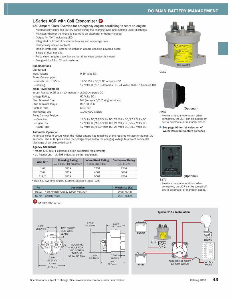
DC MAIN BATTERY MANAGEMENT
Specifi cations subject to change. See www.bluesea.com for current information. Catalog 2008
9112
PN Description Weight Lb (Kg)
9112 450 Ampere Class, 12/24 Volt ACR 0.95 (0.43)
8270 Switch Panel 0.27 (0.12)
L-Series ACR with Coil Economizer 450 Ampere Class, Override for emergency engine paralleling to start an engine· Automatically combines battery banks during the charging cycle and isolates under discharge
· Activates whether the charging source is an alternator or battery charger
· Output for “ON” indicating LED
· Integrated coil control minimizes heating and amperage draw
· Hermetically sealed contacts
· Ignition protected—safe for installation aboard gasoline powered boats
· Single or dual sensing
· Pulse circuit requires very low current draw when contact is closed
· Designed for 12 or 24 volt systems
Specifications
Coil Circuit Input Voltage 9-36 Volts DC
Power Consumption
– inrush max, 130ms 12-36 Volts DC/3.80 Amperes DC
– holding 12 Volts DC/0.13 Amperes DC, 24 Volts DC/0.07 Amperes DC
Main Power ContactsInrush Rating: 0.25 sec. (10 repeats)* 2,000 Amperes DC
Voltage Rating 60 Volts DC
Stud Terminal Size M8 (accepts 5/16" ring terminals)
Stud Terminal Torque 80-100 in-lb
Contact Form SPST-NO
Mechanical Life 1,000,000 Cycles
Relay Contact Position
– Combine 12 Volts DC/13.6 Volts DC, 24 Volts DC/27.2 Volts DC
– Open Low 12 Volts DC/12.6 Volts DC, 24 Volts DC/25.2 Volts DC
– Open High 12 Volts DC/15.0 Volts DC, 24 Volts DC/30.0 Volts DC
Automatic OperationAutomatic closure occurs when the higher battery has remained at the required voltage for at least 30
seconds. The ACR opens when the voltage drops below the charging voltage to prevent accidental
discharge of an unintended bank.
Agency Standards
• Meets SAE J1171 external ignition protection requirements
• UL Recognized - UL 508 industrial control equipment
IGNITION PROTECTED
Wire SizeCranking Rating
9.75 sec. (10 repeats)*
Intermittent Rating
5 min. (UL 1107)
Continuous Rating
(UL 1107)
1/0 500A 275A 250A
2/0 500A 450A 300A
2x2/0 800A 600A 450A
*Blue Sea Systems Engine Starting Standard (page 126) 8270(Optional)
8232(Optional)
See page 95 for full selection of Water Resistant Contura Switches
· Provides manual operation - When
connected, the ACR can be turned off,
set to automatic, or manually closed.
· Provides manual operation - When
connected, the ACR can be turned off,
set to automatic, or manually closed.
Typical 9112 Installation
HOUSEHOUSE
9112
DUAL CIRCUIT PLUS ™ BATTERY SWITCH
43
ENGINE
ENGINE
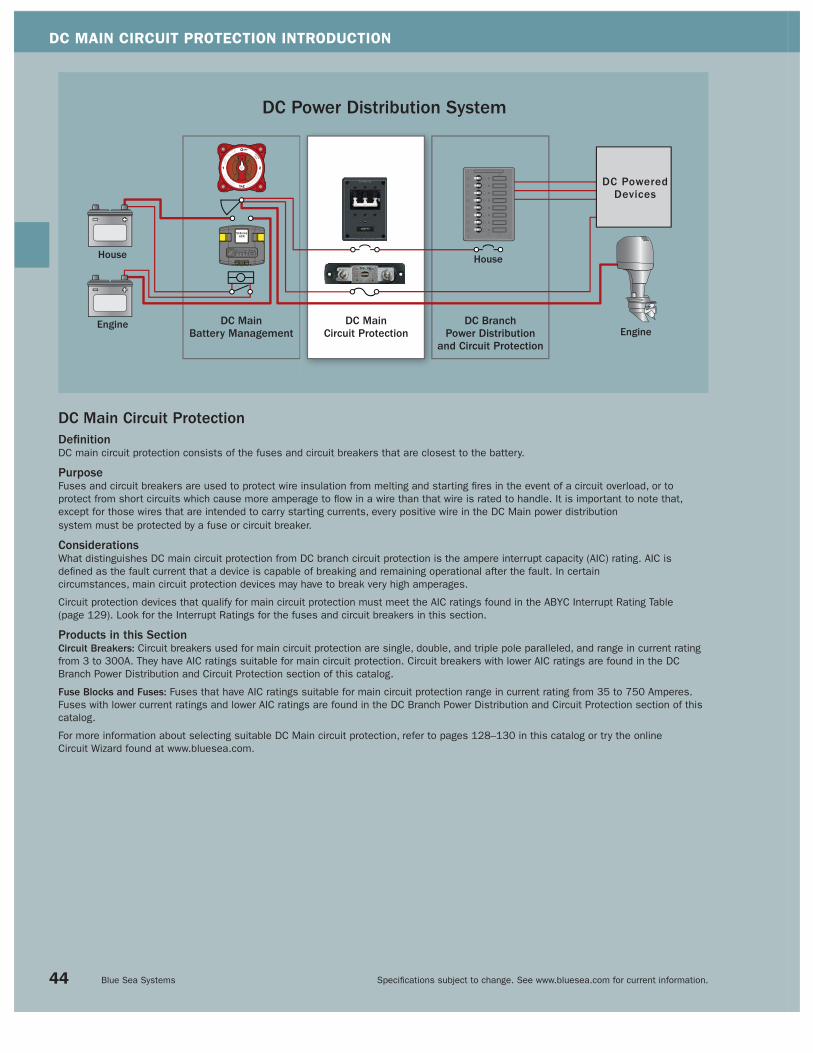
DC MAIN CIRCUIT PROTECTION INTRODUCTION
Specifi cations subject to change. See www.bluesea.com for current information. Blue Sea Systems
DC Power Distribution System
DC Main Circuit ProtectionDefi nitionDC main circuit protection consists of the fuses and circuit breakers that are closest to the battery.
PurposeFuses and circuit breakers are used to protect wire insulation from melting and starting fi res in the event of a circuit overload, or to
protect from short circuits which cause more amperage to fl ow in a wire than that wire is rated to handle. It is important to note that,
except for those wires that are intended to carry starting currents, every positive wire in the DC Main power distribution
system must be protected by a fuse or circuit breaker.
ConsiderationsWhat distinguishes DC main circuit protection from DC branch circuit protection is the ampere interrupt capacity (AIC) rating. AIC is
defi ned as the fault current that a device is capable of breaking and remaining operational after the fault. In certain
circumstances, main circuit protection devices may have to break very high amperages.
Circuit protection devices that qualify for main circuit protection must meet the AIC ratings found in the ABYC Interrupt Rating Table
(page 129). Look for the Interrupt Ratings for the fuses and circuit breakers in this section.
Products in this SectionCircuit Breakers: Circuit breakers used for main circuit protection are single, double, and triple pole paralleled, and range in current rating
from 3 to 300A. They have AIC ratings suitable for main circuit protection. Circuit breakers with lower AIC ratings are found in the DC
Branch Power Distribution and Circuit Protection section of this catalog.
Fuse Blocks and Fuses: Fuses that have AIC ratings suitable for main circuit protection range in current rating from 35 to 750 Amperes.
Fuses with lower current ratings and lower AIC ratings are found in the DC Branch Power Distribution and Circuit Protection section of this
catalog.
For more information about selecting suitable DC Main circuit protection, refer to pages 128–130 in this catalog or try the online
Circuit Wizard found at www.bluesea.com.
DC MainBattery Management
DC MainCircuit Protection
DC BranchPower Distribution
and Circuit Protection
SI-Series ACR
DC PoweredDevices
House
EngineEngine
House
44

DC MAIN CIRCUIT PROTECTION SECTION INDEX
Specifi cations subject to change. See www.bluesea.com for current information. Catalog 2008 45
Circuit Breakers Pages 46–49
Fuses Pages 50–53
DC Main Circuit Breakers Detailed information about these circuit breakers is located in the DC Branch section Page 62
Push Button Reset-Only, Interrupt Rating: 3,[email protected] DC/2,500A@28V DC
185-Series, Interrupt Rating: 3,000A DC Maximum Voltage: 42V DC
187-Series, Interrupt Rating: 5,000A@12V DC/3,000A@24V DC/1,500A@42 DC Maximum Voltage – 48V DC
C-Series Toggle, Interrupt Rating: See page xxx Maximum Voltage: See page xxx
C-Series Flat Rocker, Interrupt Rating: See page xx Maximum Voltage: See page xxx
A-Series Toggle, Interrupt Rating: 7,500A@65V DC/3,000A@250V AC Maximum Voltage: 65V DC/250V AC
Page 46
Page 46
Page 47
Page 48
Page 49
Page 62
Fuse Blocks Pages 50–53
SEA Series Fuse Block—Uses Sea Fuses Maximum Voltage: 32V DC Maximum Amperage: 300A DC
ANL Fuse Blocks—Uses ANL Fuses Maximum Voltage: 32V DC Maximum Amperage: 300A DC
ANL Heavy Fuse Blocks—Uses ANL Fuses Maximum Voltage: 32V DC Maximum Amperage: 750A DC
Class T Fuse Block—Uses Class T Fuses Maximum Voltage: 160V DC Maximum Amperage: 400A DC
Page 51
Page 52
Page 53
Terminal Fuse Block—Uses Terminal Fuses Maximum Voltage: 58V DC Maximum Amperage: 300A DC
Page 50
5 10 15 20 25 30 50 60 80 100 150 175 200 250 300
5 10 15 20 25 30 50 60 80 100 150 175 200 250 300
3 4 5 7 10 12 15 20 25 30 35 40
25 30 35 40 50 60 70 80 90 100 110 120 135 150
25 30 35 40 50 60 70 80 90 100 110 120 135 150
Sea Fuses, Interrupt Rating: 2,000A DC Maximum Voltage: 32V DC
Page 51 100 125 150 175 200 225 250 300
5 8 10 15 20 25 30 40 50
Class T Fuses, Interrupt Rating: 20,000A DC Maximum Voltage: 160V DC
Page 53 110 125 150 175 200 225 250 300 350 400
ANL Fuses, Interrupt Rating: 6,000A DC Maximum Voltage: 32V DC
Page 52 35 40 50 60 80 100 130 150 175 200 225 250 275 300 325 350 400 500 600 675 750
Page 50
Terminal Fuse, Interrupt Rating: 10,000A@14V DC/5,000A@32V DC/2,000A@58V DC Maximum Voltage: 58V DC
30 40 50 60 75 80 90 100 125 150 175 200 225 250 300
750 AmperesDC Current Ratings (Amperes)0 AmperesDC Current Ratings
A-Series Flat and Restricted OFF Rocker, Interrupt Rating: 5,000A@32V DC/3,000A@125V AC/1,500A@240V AC
Maximum Voltage: 32V DC/240V AC
Page 62 5 8 10 15 20 25 30 40 50

DC MAIN CIRCUIT PROTECTION
Specifi cations subject to change. See www.bluesea.com for current information. Blue Sea Systems
Push Button Reset-Only Thermal Circuit Breakers• Branch circuit breakers (can be used for 24-hour circuit protection)
• Incorporated into Blue Sea Systems’ waterproof circuit breaker panels (pages 56–57, 59),
Battery Main Distribution Panels (page 37), and 360 Distribution Panels (pages 10–13)
• Compact design enables high density circuit protection configurations
• Push to reset operation
• “Trip Free” design cannot be held “ON” during fault current condition
• Ignition protected—safe for installation aboard gasoline powered boats
• Optional Push Button Waterproof Boot protects circuit breaker in wet environments,
replaces dress nut mounting on circuit breakers, and resists discoloration and cracking
Specifications
Interrupt Rating 3,000 [email protected] Volts DC/2,500 Amperes@28 Volts DC
Circuit Breaker Type Thermal trip, manual push button reset only
Operating Temperature Range -10°C to +60°C
Trip Time Delay See www.bluesea.com
Weight Circuit Breaker 0.06Lb (0.03Kg)
Weight Waterproof Boots (pkg. of 5) 0.04Lb (0.02Kg)
Boot Material UV Resistant Silicone Rubber
Boot Thread Material Nickel-Plated Brass
Boot Thread 3/8"-27
Certifications and Agency Standards
• E marked
• Meets UL 1500 and ISO 8846 external ignition protection requirements
• UL Recognized—UL 1077–UL/cUL (USA and Canada), TUV certified
Panel Mount Dimensions
Surface Mount Dimensions
IGNITION PROTECTED
See page 129 for ABYC Interrupt Rating Requirements.
7110 Surface Mount7010 Panel Mount
7056
Push Button
Circuit Breakers
PN Amperage
7050 3A
7051 4A
7052 5A
7053 7A
7054 10A
7055 12A
7056 15A
7057 20A
7058 25A
7059 30A
7060 35A
7061 40A
Panel Mount
PN Amperage
7008 25A
7009 30A
7010 35A
7005 40A
7000 50A
7011 60A
7012 70A
7014 80A
7006 90A
7002 100A
7007 110A
7013 120A
7015 135A
7004 150A
Surface Mount
PN Amperage
7108 25A
7109 30A
7110 35A
7105 40A
7100 50A
7111 60A
7112 70A
7114 80A
7106 90A
7102 100A
7107 110A
7113 120A
7115 135A
7104 150A
Cut Out
413741364135
Push Button Boots
PN Color
4135 Clear
4136 White
4137 Black
See page 129 for ABYC Interrupt Rating Requirements.
185-Series Thermal Circuit Breakers• Ignition protected—safe for installation aboard gasoline powered boats
• Weather Resistant
• Combines switching and circuit breaker function into one unit
• “Trip Free”—cannot be held closed after trip
Specifications
Interrupt Rating 3,000 Amperes DC
Maximum Voltage 42 Volts DC
Circuit Breaker Type Thermally Responsive Bi-Metal Blade
Circuit Breaker Class Type III—Switchable/Manual Reset - Trip Free
Operating Temperature Range -25°C to +82°C
Terminal Stud Torque 70 in-lb
Trip Time Delay See www.bluesea.com
Case Material Phenolic
Weight Panel Mount 0.25 lb (0.11 Kg)
Surface Mount 0.30 lb (0.14 Kg)
Certifications and Agency Standards
• E marked
• Meets SAE J1171 external ignition protection requirements
46
IGNITION PROTECTED
See pages 10–13 for a full selection of related products located in the new 360 Panel System section of this catalog.

DC MAIN CIRCUIT PROTECTION
Specifi cations subject to change. See www.bluesea.com for current information. Catalog 2008
7198 7199
PN Description Height in" (mm) Width in" (mm) Weight Lb (Kg)
7198 Trim Bezel 3.34 (84.71) 2.44 (61.90) 0.04 (0.02)
7199 Mounting Panel 4.00 (101.60) 3.00 (76.20) 0.12 (0.05)
185-Series Thermal Circuit Breaker Mounting Systems• Used with 185-Series Thermal Panel Mount Circuit Breakers (page 46)
• 7199 Heavy 1/8" aluminum 5052 Alloy
• 7199 Two-part polyurethane slate gray finish
• 7198 Self trimming molded rubber bezel
Panel MountPN Amperage
7035 25A
7036 30A
7037 35A
7038 40A
7039 50A
7040 60A
7041 70A
7042 80A
7043 90A
7044 100A
7045 110A
7046 120A
7047 135A
7048 150A
Surface Mount PN Amperage
7135 25A
7136 30A
7137 35A
7138 40A
7139 50A
7140 60A
7141 70A
7142 80A
7143 90A
7144 100A
7145 110A
7146 120A
7147 135A
7148 150A
IGNITION PROTECTED
Panel Mount Dimensions
Surface Mount Dimensions
187-Series Thermal Circuit Breakers • Ignition protected—safe for installation aboard gasoline powered boats
• Waterproof
• Combines switching and circuit protection into a single device
• Single lever operation—clearly visible
• “Trip Free” design cannot be held “ON” during fault current condition
• Recessed mounting holes for clean appearance
• Robust 5/16"-18 terminals provide high torque connections
Specifications
Interrupt Rating 5,000 Amperes@12 Volts DC
3,000 Amperes@24 Volts DC
1,500 Amperes@42 Volts DC
Maximum Voltage Rating 48 Volts DC
Circuit Breaker Type Thermally Responsive Bi-Metal Blade
Circuit Breaker Class Type III—Switchable/Manual Reset—Trip Free
Operating Temperature Range -25°C to +82°C
Terminal Stud Torque 90 in-lb
Trip Time Delay See www.bluesea.com
Case Material Thermoset Polyester
Weight Panel Mount 0.50 lb (0.23 Kg)
Surface Mount 0.58 lb (0.26 Kg)
Certifications and Agency Standards
• E marked
• Meets SAE J1171 external ignition protection requirements
Robust 5/16" terminals
provide high torque
connections
Large clearance around
terminal studs accepts
up to 1/0 AWG lugs
7139Surface Mount
7039Panel Mount
Self-trimming case
eliminates need for
mounting panels or
trim bezels
Round case for easy
installation with standard
sized hole saw
See page 129 for ABYC Interrupt Rating Requirements.
47
IGNITION PROTECTED

DC MAIN CIRCUIT PROTECTION
Specifi cations subject to change. See www.bluesea.com for current information. Blue Sea Systems
PN Panel PN Circuit Breaker Installed Poles Amperage Weight Lb (Kg)
7262 7267 2* 150A 0.95 (0.45)
7263 7268 2* 175A 0.95 (0.45)
7264 7269 2* 200A 0.95 (0.45)
7265 7270 3* 250A 1.21 (0.59)
7266 7271 3* 300A 1.21 (0.59)
C-Series Toggle Circuit Breaker Panels• Heavy 1/8" aluminum 5052 Alloy
• Two-part polyurethane slate gray finish
• LED indicates power “ON”
Specifications
LED Power Consumption 5 Milliwatts
C-Series Toggle Circuit Breakers• Provides overcurrent protection for inverters, bow thrusters, and windlasses
• Combines switching and circuit protection into a single device
• “Trip Free”—cannot be held closed after trip
• 7250I Ignition protected—safe for installation aboard gasoline powered boats
• 7250I meets UL 1500 and ISO 8846 external ignition protection requirements
Specifications
Interrupt Rating See Interrupt Ratings tables below
Maximum Voltage See Interrupt Ratings tables below
Circuit Breaker Type Magnetic Hydraulic
Operating Temperature Range -40°C to +85°C
Terminal Stud 1/4"-20 Tin-Plated Brass - Maximum torque 35 in-lb
Trip Time Delay See www.bluesea.com
Rated Switch Cycles 10,000 @ rated amperage and voltage
Case Material Phenolic
Mounting Screw Stainless Steel #6-32—Recommended torque 6-8 in-lb
Agency Standards
• Meets SAE J1171 external ignition protection requirements—7250I Only
PN Color Poles Amperage Weight Lb (Kg)
7350 - White 1* 5A 0.28 (0.13)
7351 - White 1* 10A 0.28 (0.13)
7352 - White 1* 15A 0.28 (0.13)
7353 - White 1* 20A 0.28 (0.13)
7354 - White 1* 25A 0.28 (0.13)
7355 - White 1* 30A 0.28 (0.13)
7244 - White 1* 50A 0.36 (0.17)
7246 - White 1* 60A 0.36 (0.17)
7248 - White 1* 80A 0.36 (0.17)
7250 - White 1* 100A 0.36 (0.17)
7250I Red 1* 100A 0.36 (0.17)
7267 - White 2 150A 0.64 (0.31)
7268 - White 2 175A 0.64 (0.31)
7269 - White 2 200A 0.64 (0.31)
7270 - White 3 250A 0.93 (0.46)
7271 - White 3 300A 0.93 (0.46)
* Single pole circuit breakers are AC/DC ratedSee page 49 for C-Series Toggle Circuit Breaker Mounting Panels.** Multiple pole versions have 5/16" stud on bus
7266
72707267
7250
1 UL Recognized2 No Agency Approvals
Interrupt Ratings (see ABYC Interrupt Rating Requirements page 129)
C-Series Toggle Circuit Breakers - Single Pole
UL 1077 - UL/CSA
(US/Canada)1EN60934 - TUV
(Europe)
Voltage Current Interrupt Ratings Interrupt Ratings
80V DC 5-100A 10,000A -
125V AC 5-100A 5,000A -
250V AC 5-100A 5,000A 5,000A
C-Series Toggle Circuit Breakers - Double and Triple Pole
Voltage Current Interrupt Ratings Interrupt Ratings
65V DC 150-300A 5,000A2 -
Panel Cutout Detail
7250I
**
C-Series Toggle Circuit Breaker - 7250I Single Pole (Ignition Protected)
UL 1077 - UL/CSA
(US/Canada)1EN60934 - TUV
(Europe)
Voltage Current Interrupt Ratings Interrupt Ratings
48V DC 100A 5,000A -
125V AC 100A 1,500A -
IGNITION PROTECTED
48
* Paralleled Poles

DC MAIN CIRCUIT PROTECTION
Specifi cations subject to change. See www.bluesea.com for current information. Catalog 2008
C-Series Toggle Circuit Breaker Mounting Panels• Designed for C-Series Toggle Circuit Breakers
• Heavy 1/8" aluminum 5052 Alloy
• Two-part polyurethane slate gray finish
• Accepts Blue Sea Systems Large Format Labels (page 100)
• Accepts Blue Sea Systems “ON” indicating LEDs (page 97)
• Industry standard height and width
• Panel Plug Kit included
• Panel plugs can be inserted to fill blank positions
• Panel Plug Kit 8089 includes Circuit Breaker Mounting Screws,
panel plug, LED plug, and blank label
PN Description Width in" (mm) Height in" (mm) Weight Lb (Kg)
8087 8 Position 5.25 (133.35) 7.50 (190.50) 0.40 (0.18)
8088 3 Position 5.25 (133.35) 3.75 (95.25) 0.24 (0.11)
8089 Panel Plug Kit - - 0.10 (0.04)
7551
7540
80878088
See page 48 for C-Series Toggle Circuit Breakers.
7554
49
C-Series Flat Rocker Circuit Breakers• Rocker actuator is fl ush in the “ON” position, eliminating the risk of
accidental switching, color actuator indicates “OFF” position
• Provides overcurrent protection for inverters, bow thrusters, and windlasses
• Combines switching and circuit protection into a single device
• “Trip Free”—cannot be held closed after trip
• Single poles are ignition protected—safe for installation aboard gasoline powered boats
Specifications
Interrupt Rating See Interrupt Ratings tables below
Maximum Voltage See Interrupt Ratings tables below
Circuit Breaker Type Magnetic Hydraulic
Operating Temperature Range -40°C to +85°C
Terminal Stud 1/4"-20 Tin-Plated Brass—Maximum torque 35 in-lb
Trip Time Delay See www.bluesea.com
Rated Switch Cycles 10,000 @ rated amperage and voltage
Case Material Phenolic
Mounting Screw Stainless Steel #6-32—Recommended torque 6-8 in-lb
Certifications and Agency Standards
• Single poles meet SAE J1171, UL 1500 and ISO 8846 external ignition protection requirements
1 UL Recognized
Interrupt Ratings (see ABYC Interrupt Rating Requirements page 129)
C-Series Flat Rocker Circuit Breakers - Single Pole (Ignition Protected)
UL 1077 - UL/CSA
(US/Canada)1EN60934 - TUV
(Europe)
Voltage Current Interrupt Ratings Interrupt Ratings
32V DC 5-100A 5,000A -
125V AC 5-100A 3,000A -
240V AC 5-50A 3,500A -
C-Series Flat Rocker Circuit Breakers - Double and Triple Pole
Voltage Current Interrupt Ratings Interrupt Ratings
48V DC 150-300A 5,000A -
48V DC 150-200A - 5,000A
IGNITION PROTECTED
PN Poles Amperage Weight Lb (Kg)
7540 1 5A 0.28 (0.13)
7541 1 10A 0.28 (0.13)
7542 1 15A 0.28 (0.13)
7543 1 20A 0.28 (0.13)
7544 1 25A 0.28 (0.13)
NEW PRODUCT
Cutout DetailDouble and Triple PoleSingle Pole
PN Poles Amperage Weight Lb (Kg)
7475 2* 150A 0.64 (0.31)
7551 2* 175A 0.64 (0.31)
7476 2* 200A 0.64 (0.31)
7477 3* 250A 0.93 (0.46)
7554 3* 300A 0.93 (0.46)
PN Poles Amperage Weight Lb (Kg)
7545 1 30A 0.28 (0.13)
7546 1 50A 0.36 (0.17)
7547 1 60A 0.36 (0.17)
7548 1 80A 0.36 (0.17)
7549 1 100A 0.36 (0.17)
* Paralleled Poles

DC MAIN CIRCUIT PROTECTION
Specifi cations subject to change. See www.bluesea.com for current information. Blue Sea Systems 50
Terminal Fuse BlockEasy and economical solution for satisfying ABYC 7" circuit protection rule.Mounts on 3/8" (M10) battery post, battery switch, and busbar terminals.
• Compact, high-amp fuse—Appropriate for DC Main, inverter, windlass, and
bow thruster circuit protection
• Provides high current protection in tight space constraints
• Weatherproof—suitable for small open-cockpit boats and other
harsh environments
• Insulating nut and cap prevents accidental shorts
Specifications
Maximum Voltage 58 Volts DC
Recommended Torque 75 in-lbs Maximum
Terminal Stud 1/4"-20
Fuses Available 30–300 Amperes DC
0.906"23.00mm
1.09"27.8mm
0.64"16.3mm
0.325"8.25mm HOLE DIAMETER
AMPERAGE VOLTAGEDATE CODE
AMPERAGECOLOR CODE
PN Amperage Color Weight Lb (Kg)
5175 30A LT Green 0.06 (0.02)
5176 40A LT Blue 0.06 (0.02)
5177 50A Red 0.06 (0.02)
5178 60A Gold 0.06 (0.02)
5180 75A Brown 0.06 (0.02)
5181 80A Lime 0.06 (0.02)
5182 90A Purple 0.06 (0.02)
5183 100A Yellow 0.06 (0.02)
5184 125A Green 0.06 (0.02)
5185 150A Orange 0.06 (0.02)
5186 175A white 0.06 (0.02)
5187 200A Blue 0.06 (0.02)
5188 225A Tan 0.06 (0.02)
5189 250A Pink 0.06 (0.02)
5190 300A Grey 0.06 (0.02)
IGNITION PROTECTED
e.
2.29"58.3mm
0.87"22.0mm
0.24"6.0mm
1.65"42.0mm
0.10"2.5mm
0.79"20.0mmWIDTH
3/8" (M10) MOUNTING
HOLE
1/4"-20 STUD
2.30"58.4mm
PN Description Weight Lb (Kg)
5191 Terminal Fuse Block 0.16 (0.07)
Single Battery Solution:1. No battery switch
2. 24 hour circuits off of battery
Dual Battery Solution:1. ON/OFF battery switch
2. Selector battery switch
3. Dual Circuit Plus™ battery switch
High-Amp Load Solution:1. Windlass
2. Bow Thruster
3. Inverter
TO ENGINESWITCH
TO HOUSELOADS
TO ENGINE
TO HOUSE LOADS
POWER INPUT
TO INVERTER
TO BOWTHRUSTER
Terminal Fuse*
• Interrupt Rating satisfi es ABYC requirements for DC
Main circuit protection on large battery banks
• Ignition protected—safe for installation aboard
gasoline powered boats
• Clear window—visual indication of blown condition
• Color coded for each amperage
Specifications
Interrupt Rating 10,000 Amperes@14 Volts DC
5,000 Amperes@32 Volts DC
2,000 Amperes@58 Volts DC
Maximum Voltage 58 Volts DC
Trip Time Delay See www.bluesea.com
Certifications and Agency Standards
• Meets SAE J1171 external ignition
protection requirements
• Rated IP66—withstands water from heavy seas
ABYC E-11.12.1.1.1. Each ungrounded conductor
connected to a battery charger, alternator, or other
charging source, shall be provided with overcurrent
protection within a distance of seven inches (175mm)
of the point of connection to the DC electrical
system or to the battery.
5191 (fuse not included)
5189
NEW PRODUCT
* For use only with Terminal Fuse Block
BUSBAR
BATTERYSWITCHBATTERY
Available Fall, 2007
Available Fall, 2007

DC MAIN CIRCUIT PROTECTION
Specifi cations subject to change. See www.bluesea.com for current information. Catalog 2008
SEA Fuse Blocks
5001 (fuse not included)
SEA Fuses• Economical fuse for 100–300 Ampere circuit protection
Specifications
Interrupt Rating 2,000 Amperes DC
Maximum Voltage 32 Volts DC
Trip Time Delay See www.bluesea.com
PN Amperage Weight Lb (Kg)
5101 100A 0.06 (0.03)
5102 125A 0.06 (0.03)
5103 150A 0.06 (0.03)
5104 175A 0.06 (0.03)
5105 200A 0.06 (0.03)
5106 225A 0.06 (0.03)
5107 250A 0.06 (0.03)
5108 300A 0.06 (0.03)
PN Description Amperage Weight Lb (Kg)
5000 Fuse Block without Cover 100-300A 0.17 (0.07)
5001 Fuse Block with Cover 100-300A 0.35 (0.16)
5106
• Economical system for 100–300 Ampere fusing
• Insulating cover satisfies ABYC/USCG insulation requirements and
protects conductive components
• Cover breakouts allow wire access in any direction
• For use on systems up to 32 Volts DC
• Insert molded studs ensure secure fuse mounting
• Stainless steel studs provide resistance to corrosion and allow
high torque for excellent electrical contact
• 5/16"-18 studs accept 5/16" (M8) ring terminals,
14 AWG to 2/0 AWG wire
• UL 94-V0 base resists high heat
Specifications
Maximum Amperage 300 Amperes DC
Maximum Voltage 32 Volts DC
Maximum Torque 110 in-lb (12.40 N-m)
Base Material Reinforced PBT
Cover Material Polycarbonate
SEA Fuses available 100-300 Amperes DC
51
Pursuit C310 Center Console—Courtesy of Pursuit Boats

DC MAIN CIRCUIT PROTECTION
Specifi cations subject to change. See www.bluesea.com for current information. Blue Sea Systems 52
5005 ANL Fuse Block(fuse not included)
ANL Fuse BlocksCommon Features• For use on systems up to 32 Volts DC
5003:
Large terminals accept 5/16" (M8) ring terminals up to 4/0 AWG
5003/5005:
Insulating cover satisfies ABYC/USCG insulation requirements
5004/5005:
• Large 5/16"-18 studs accept 5/16" (M8) ring terminals, from 14 AWG to 2/0 AWG wire
• Stainless steel studs provide resistance to corrosion and high torque for excellent
electrical contact
• Swing out design allows replacement of the fuse without removing fasteners
• UL 94-V0 base resists high heat
5005:
Cover breakouts allow wire access in any direction
PN Description Amperage Weight Lb (Kg)
5003 ANL Heavy Fuse Block with Cover 35-750A 1.45 (0.66)
5004 ANL Fuse Block without Cover 35-300A 0.18 (0.08)
5005 ANL Fuse Block with Cover 35-300A 0.35 (0.16)
Specifications 5003 5004 5005
Maximum Amperage 750 Amperes DC 300 Amperes DC 300 Amperes DC
Maximum Voltage 32 Volts DC 32 Volts DC 32 Volts DC
Maximum Torque 110 in-lb (12.40 N-m) 132 in-lb (14.91 N-m) 132 in-lb (14.91 N-m)
Base Material Reinforced PBT Reinforced PBT Reinforced PBT
Cover Material Polycarbonate - Polycarbonate
Fuse Mounting Blocks Tin-Plated Copper - -
ANL Fuses Available 35–750 Amperes 35–300 Amperes 35–300 Amperes
35-750 Ampere ANL Fuses• 6,000 Ampere Interrupt Rating satisfies ABYC requirements for main DC circuit protection
on large battery banks
• Ignition protected—safe for installation aboard gasoline powered boats (35–500 Amperes only)
• Silver-plated connector blades for corrosion resistance
• Visible indication of blown fuse condition
Specifications
Interrupt Rating 6,000 Amperes DC
Maximum Voltage 32 Volts DC
Trip Time Delay See www.bluesea.com
Certifications and Agency Standards
ISO 8846
• Meets ISO 8846 and SAE J1171 external ignition protection requirements (35–500 Amperes only)
• USCG Title 33 CFR 183.410(a) and UL 1500 (35–500 Amperes only)
ANL Fuse
5003 Dimensions
PN Amperage Weight Lb (Kg)
5164 35A 0.05 (0.02)
5165 40A 0.05 (0.02)
5122 50A 0.05 (0.02)
5123 60A 0.05 (0.02)
5124 80A 0.05 (0.02)
5125 100A 0.05 (0.02)
5126 130A 0.05 (0.02)
5127 150A 0.06 (0.03)
5128 175A 0.06 (0.03)
5129 200A 0.06 (0.03)
5130 225A 0.06 (0.03)
5131 250A 0.07 (0.03)
5132 275A 0.07 (0.03)
5133 300A 0.07 (0.03)
5134 325A 0.07 (0.03)
5135 350A 0.07 (0.03)
5136 400A 0.08 (0.04)
5137 500A 0.08 (0.04)
5161 - 600A 0.08 (0.04)
5162 - 675A 0.08 (0.04)
5163 - 750A 0.08 (0.04)
5003 ANL Heavy Fuse Block(fuse not included)
5005 Dimensions
IGNITION PROTECTED
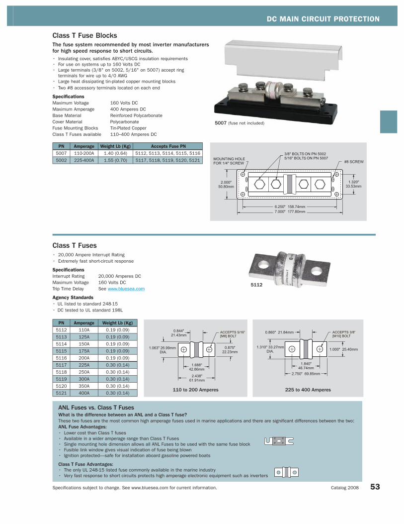
DC MAIN CIRCUIT PROTECTION
Specifi cations subject to change. See www.bluesea.com for current information. Catalog 2008
5112
Class T Fuses• 20,000 Ampere Interrupt Rating
• Extremely fast short-circuit response
Specifications
Interrupt Rating 20,000 Amperes DC
Maximum Voltage 160 Volts DC
Trip Time Delay See www.bluesea.com
Agency Standards
• UL listed to standard 248-15
• DC tested to UL standard 198L
Class T Fuse Blocks The fuse system recommended by most inverter manufacturers for high speed response to short circuits.• Insulating cover, satisfies ABYC/USCG insulation requirements
• For use on systems up to 160 Volts DC
• Large terminals (3/8" on 5002, 5/16" on 5007) accept ring
terminals for wire up to 4/0 AWG
• Large heat dissipating tin-plated copper mounting blocks
• Two #8 accessory terminals located on each end
Specifications
Maximum Voltage 160 Volts DC
Maximum Amperage 400 Amperes DC
Base Material Reinforced Polycarbonate
Cover Material Polycarbonate
Fuse Mounting Blocks Tin-Plated Copper
Class T Fuses available 110–400 Amperes DC
PN Amperage Weight Lb (Kg) Accepts Fuse PN
5007 110-200A 1.40 (0.64) 5112, 5113, 5114, 5115, 5116
5002 225-400A 1.55 (0.70) 5117, 5118, 5119, 5120, 5121
PN Amperage Weight Lb (Kg)
5112 110A 0.19 (0.09)
5113 125A 0.19 (0.09)
5114 150A 0.19 (0.09)
5115 175A 0.19 (0.09)
5116 200A 0.19 (0.09)
5117 225A 0.30 (0.14)
5118 250A 0.30 (0.14)
5119 300A 0.30 (0.14)
5120 350A 0.30 (0.14)
5121 400A 0.30 (0.14)110 to 200 Amperes 225 to 400 Amperes
ANL Fuses vs. Class T FusesWhat is the difference between an ANL and a Class T fuse?These two fuses are the most common high amperage fuses used in marine applications and there are signifi cant differences between the two:
ANL Fuse Advantages:• Lower cost than Class T fuses
• Available in a wider amperage range than Class T Fuses
• Single mounting hole dimension allows all ANL Fuses to be used with the same fuse block
• Fusible link window gives visual indication of fuse being blown
• Ignition protected—safe for installation aboard gasoline powered boats
Class T Fuse Advantages:• The only UL 248-15 listed fuse commonly available in the marine industry
• Very fast response to short circuits protects high amperage electronic equipment such as inverters
5007 (fuse not included)
53

DC BRANCH POWER DISTRIBUTION AND CIRCUIT PROTECTION INTRODUCTION
Specifi cations subject to change. See www.bluesea.com for current information. Blue Sea Systems
AC Power Distribution System
DC Branch Power Distribution and Circuit ProtectionDefi nitionThe portion of the DC power distribution system that conducts power from the DC Main Circuit Protection to the load devices at the end
of the circuit. Typically, the DC Branch Distribution System carries lower DC current, roughly currents below 50 Amperes.
PurposeThe distribution of high amperages from a single cable into lower amperages with multiple wires, circuit protection, and switching. These three
functions may be consolidated into a single device as in the case of a circuit breaker distribution panel, or each function may reside
in separate devices.
Products in this SectionWeatherDeck™ Waterproof Circuit Breaker Panels and Fuse Panels are designed for fl ybridge and open cockpit applications. They contain
toggle switches, backlit circuit labels, and either push-button-reset circuit breakers or blade fuses. These panels are rated IP67—temporary
immersion for 30 minutes.
Contura Waterproof Circuit Breaker Panels and Fuse Panels also are designed for fl ybridge and open cockpit applications. They contain water
resistant ON/OFF Contura switches with embedded ON-indicating LEDs, and either push-button-reset circuit breakers or glass fuses. Contura
Waterproof panels are available with 3, 4, 6, and 8 circuit positions. These panels are rated IP66—able to withstand water from heavy seas.
A-Series Toggle Circuit Breaker Panels: There are a wide variety of circuit breaker panels for below deck applications. Panels are available
with 3 to 35 circuits, some panels have analog or digital meters, and some have main circuit protection.
Fuse Blocks and Fuses: Blue Sea Systems’ multi-circuit fuse blocks are available for below deck applications. ST Glass Fuse Blocks have 6
circuits and are available with and without a negative bus. ST Blade Fuse Blocks are available with 6 or 12 circuits, and with and without a
negative bus. Maxi fuse blocks are economical and convenient single circuit devices.
Circuit Breakers: Blue Sea Systems’ single pole circuit breakers for branch circuit protection range in current rating from 3 to 100A, and
are available in toggle, rocker, and push button thermal models.
Look for the Interrupt Ratings for the fuses and circuit breakers in this section.
Circuit breakers and fuses with higher current ratings and AIC ratings are found in DC Main Circuit Protection.
For more information about selecting suitable DC branch circuit protection, refer to pages 128–130 in this catalog.
DC MainBattery Management
DC MainCircuit Protection
DC BranchPower Distribution
and Circuit Protection
SI-Series ACR
DC PoweredDevices
House
EngineEngine
House
54

DC BRANCH POWER DISTRIBUTION AND CIRCUIT PROTECTION SECTION INDEX
Specifi cations subject to change. See www.bluesea.com for current information. Catalog 2008 55
Circuit Protected Panels Pages 56–61 Fuse Blocks Pages 63–65
Waterproof Fuse and Circuit Breaker Panels
ST Glass and ST Blade Fuse Blocks(Screw Terminal)
A-Series Circuit Breaker Panels MAXI™ Fuse Block
DC Main Circuit Breakers Detailed information about these circuit breakers is located in the DC Main Section Pages 46–49
Single Pole Circuit Breakers Page 62
Fuses Page 65
A-Series Restricted OFF Rocker, 1 Pole—Appropriate for DC Branch and 24-hour circuit protectionInterrupt Rating: 5,000A@32V DC/3,000A@125V AC/1,500A@250V AC Maximum Voltage: 32V DC/250V AC
Page 62
Page 62
Page 62
A-Series Toggle, 1 Pole—Appropriate for DC Branch circuit protectionInterrupt Rating: 7,500A@65V DC / 3,000A@250V AC Maximum Voltage: 65V DC/250V AC
5 8 1 0 1 5 2 0 2 5 3 0 4 0 5 0
5 8 1 0 1 5 2 0 2 5 3 0 4 0 5 0
5 8 1 0 1 5 2 0 2 5 3 0 4 0 5 0
ATO/ATC Fuse—Appropriate for small electronic devices Interrupt Rating: 1,000A DC Maximum Voltage: 32V DC
Page 65 1 2 3 4 5 7. 5 1 0 1 5 2 0 2 5 3 0
Push Button Reset-Only—Appropriate for 24-hour circuit protection Interrupt Rating: 3,[email protected] DC/2,500A@28V DC
Page 46 3 4 5 7 10 12 15 20 25 30 35 40
150 AmperesDC Current Ratings (Amperes)0 AmperesDC Current Ratings
A-Series Flat Rocker, 1 Pole—Appropriate for DC Branch and 24-hour circuit protectionInterrupt Rating: 5,000A@32V DC/3,000A@125V AC/1,500A@250V AC Maximum Voltage: 32V DC/250V AC
185-Series—Appropriate for DC Main circuit protection with battery banks under 1,000 CCA in adverse environmentsInterrupt Rating: 3,000A DC Maximum Voltage: 42V DC
Page 46 25 30 35 40 50 60 70 80 90 100 110 120 135 150
MAXI™ Fuse—Economical high amp branch circuit protection Interrupt Rating: 1,000A DC Maximum Voltage: 32V DC
Page 65 30 40 50 60 70 80
C-Series Toggle, 1 Pole—Appropriate for DC Main circuit protectionInterrupt Rating: 10,000A@80V DC/5,000A@250V AC Maximum Voltage: 80V DC/250V AC
Page 48 5 1 0 1 5 2 0 2 5 3 0 5 0 6 0 8 0 1 0 0
C-Series Flat Rocker, 1 Pole— Appropriate for DC Main circuit protectionInterrupt Rating: 5,000A@32V DC/3,000A@125V AC Maximum Voltage: 32V DC/240V AC
Page 49 5 1 0 1 5 2 0 2 5 3 0 5 0 6 0 8 0 1 0 0
187-Series—Appropriate for DC Main circuit protection with battery banks over 1,000 CCA in adverse environmentsInterrupt Rating: 5,000A@12V DC / 3,000A@24V DC/1,500A@42 DC Maximum Voltage: 48V DC
Page 47 25 30 35 40 50 60 70 80 90 100 110 120 135 150
See page 9 for a full selection of related products locatedin the new 360 Panel System section of this catalog.
Pages 56–59 Pages 63–64
Pages 60–61 Page 65

DC BRANCH POWER DISTRIBUTION AND CIRCUIT PROTECTION
Specifi cations subject to change. See www.bluesea.com for current information. Blue Sea Systems
WeatherDeckTM Waterproof Circuit Breaker Panels • Designed for flybridge and open cockpit applications
• Designed for 12 or 24 Volt systems
• Constructed from corrosion resistant materials
• Integrated Push Button Reset Only Circuit Breakers for circuit protection
• Independent label backlighting allows switching and dimming
• Backlighting is compatible with all Blue Sea Systems’
Digital Dimmers (page 99)
• UV stabilized and weather resistant faceplate
• Rated IP67—temporary immersion for 30 minutes
• Rugged UV stabilized waterproof boots
• Green LEDs illuminate circuit labels
• Panels can be mounted in four different orientations (page 57)
• Available in 4 and 6 circuit models
• Includes 4215—Square Format Label Set (pages 100–101)
Specifications
Maximum Voltage 24 Volts DC
Maximum Amperage Per Circuit 15 Amperes@12 Volts DC
9 Amperes@24 Volts DC
Panel Cumulative Rating 45 Amperes
Switch Type OFF/ON Toggle with Waterproof boot (page 94)
Switch Rating 15 Amperes Maximum
Backlighting Voltage 12 Volts DC Nominal
Backlighting Amperage Draw 10mA/Illuminated Circuit
Circuit Breaker Type Thermal Trip, Manual Reset Only
with waterproof boot (page 46)
Circuit Breaker Rating 15 Amperes
Panel Material Reinforced Thermoplastic
Cover Material UV Resistant Thermoplastic
Agency Standards
• Rated IP67—temporary immersion per IEC60529-degree of protection
provided by enclosure
360° circuit labels
conveniently read
in any mounted
orientation
Integrated switch
guards prevent
accidental
switching
Green LEDs
illuminate circuit
labels
Rugged UV stabilized waterproof boots protect Push Button Reset Only Thermal Circuit Breakers (page 46)
Rugged UV stabilized waterproof boots protect WeatherDeck™ Toggle Switches(page 94)
Waterproof rated IP67-temporary immersion for 30 minutes
PN Color Description[A] Width
in" (mm)
[B] Mounting Centers
in" (mm)
[C] Height
in" (mm)
[D] Mounting Centers
in" (mm)
Mounting Depth
in" (mm)Weight Lb (Kg)
4374 Gray 4 Position 4.25 (107.95) 3.69 (93.73) 4.30 (109.22) 3.74 (95.00) 3.50 (88.90) 0.97 (0.44)
4376 Gray 6 Position 4.25 (107.95) 3.69 (93.73) 6.00 (152.40) 5.44 (138.18) 3.50 (88.90) 1.36 (0.62)
4384 White 4 Position 4.25 (107.95) 3.69 (93.73) 4.30 (109.22) 3.74 (95.00) 3.50 (88.90) 0.97 (0.44)
4386 White 6 Position 4.25 (107.95) 3.69 (93.73) 6.00 (152.40) 5.44 (138.18) 3.50 (88.90) 1.36 (0.62)
With Cover Without Cover
WeatherDeck™ Toggle
Switches available in single
pole-double throw, double
pole-double throw and
momentary styles (page 94)
56

DC BRANCH POWER DISTRIBUTION AND CIRCUIT PROTECTION
Specifi cations subject to change. See www.bluesea.com for current information. Catalog 2008
Waterproof boots protect
Push Button Circuit Breakers
30 Square Format Labels (4215)
included for circuit identifi cation
(pages 100–101)
Labels can be rotated 360°
according to mounting orientation
UV stabilized faceplate snaps on and off,
providing access to components, and
concealing mounting screws
4386
4 Position - White
4374
4 Position - Gray
4374 43844384
6 Position - White
43864376
6 Position - Gray
4376
Panels can be mounted in 4 orientations to expand
location possibilities—Circuit labels can be applied accordingly.
Four Mounting Orientations
57

DC BRANCH POWER DISTRIBUTION AND CIRCUIT PROTECTION
Specifi cations subject to change. See www.bluesea.com for current information. Blue Sea Systems 58
PN Description ColorWidth
in" (mm)
Height
in" (mm)
Width Mounting Centers
in" (mm)
Height Mounting Centers
in" (mm)Weight Lb (Kg)
4302 2 Position Gray 3.88 (98.55) 2.60 (66.04) 3.31 (84.07) 2.04 (51.82) 0.52 (0.24)
4304 4 Position Gray 3.88 (98.55) 4.30 (109.22) 3.31 (84.07) 3.74 (95.00) 0.90 (0.41)
4306 6 Position Gray 3.88 (98.55) 6.00 (152.40) 3.31 (84.07) 5.44 (138.18) 1.15 (0.52)
4308 8 Position Gray 3.88 (98.55) 7.70 (195.58) 3.31 (84.07) 7.14 (181.36) 1.55 (0.70)
4312 2 Position White 3.88 (98.55) 2.60 (66.04) 3.31 (84.07) 2.04 (51.82) 0.52 (0.24)
4314 4 Position White 3.88 (98.55) 4.30 (109.22) 3.31 (84.07) 3.74 (95.00) 0.90 (0.41)
4316 6 Position White 3.88 (98.55) 6.00 (152.40) 3.31 (84.07) 5.44 (138.18) 1.15 (0.52)
4318 8 Position White 3.88 (98.55) 7.70 (195.58) 3.31 (84.07) 7.14 (181.36) 1.55 (0.70)
Panels can be mounted in 4 orientations to expand location possibilities - Circuit labels can be applied accordingly.
Four Mounting Orientations
4302
4304
430643084308
8 Position - Gray
4306
6 Position - Gray
4304
4 Position - Gray
4302
2 Position - Gray
WeatherDeckTM Waterproof Fuse Panels • Designed for flybridge and open cockpit applications
• Designed for 12 Volt systems
• Constructed from corrosion resistant materials
• Integrated ATO/ATC fuse-based circuit protection
• Independent label backlighting circuit for remote switching and dimming
• Backlighting is compatible with all Blue Sea Systems’ Digital Dimmers
(page 99)
• UV stabilized and weather resistant faceplate
• Rated IP67—temporary immersion for 30 minutes
• Rugged UV stabilized waterproof boots
• Panels can be mounted in four different orientations
• Available in 2, 4, 6, and 8 circuit models
• Includes 4215—Square Format Label Set (pages 100–101)
Specifications
Maximum Voltage 12 Volts DC
Maximum Amperage Per Circuit 15 Amperes
Panel Cumulative Rating 2 Position—30 Amperes
4 Position—60 Amperes
6 Position—90 Amperes
8 Position—100 Amperes
Switch Type OFF/ON Toggle with waterproof boot
(page 94)
Switch Rating 15 Amperes maximum
Backlighting Voltage 12 Volts DC Nominal
Backlighting Current 10mA/Illuminated Circuit
Fuse Type ATO/ATC Automotive Blade-Type
Fuses Available 1–40 Amperes
Panel Material Reinforced Thermoplastic
Cover Material UV Resistant Thermoplastic
Agency Standards
• Rated IP67—temporary immersion per IEC60529-degree of protection
provided by enclosure
360° circuit labels
conveniently read
in any mounted
orientation
Integrated switch
guards prevent
accidental switching
Bi-colored LEDs
illuminate circuit
labels to quickly
identify “OFF” (Red),
“ON” (Green), or “BLOWN
(No color)” circuits
Toggle Switch available
in single pole-double throw,
double pole-double throw, and
momentary styles
UV stabilized faceplate snaps
on and off, providing access to
components, and concealing
mounting screws
Fuses are easily accessed
from the front of the panel
30 Square Format Labels
(4215) included for circuit
identifi cation (pages 100, 101)
Fuses fully sealed with
silicone rubber cover
Labels can be rotated
360° according to
mounting orientation
Waterproof rated IP67—temporary immersion for 30 minutes

DC BRANCH POWER DISTRIBUTION AND CIRCUIT PROTECTION
Specifi cations subject to change. See www.bluesea.com for current information. Catalog 2008
6 Position - Vertical
8053
3 Position - Vertical
8054
8 Position - Horizontal
8261
4 Position - Horizontal
8262
8 Position - Horizontal
8271
6 Position - Vertical
8373
3 Position - Vertical
8374
4 Position - Horizontal
8272
Waterproof rated IP66—withstands water from heavy seas
IGNITION PROTECTED
Contura Waterproof Panels
Common Features• Designed for flybridge and open cockpit applications
• Designed for 12 or 24 Volt systems
• ON-OFF Contura Switches
• Watertight mounting gasket
• Rated IP66—withstands water from heavy seas
• Countersunk mounting holes throughout
• Heavy 1/8" aluminum material
• “ON” indicating LEDs embedded in switch
• MIL-C-5541C or equivalent immersion undercoating for lifetime
corrosion resistance
• Completely wired and ready to install
Circuit Breaker Panel Features• Push Button Circuit Breaker with waterproof boot (page 46)
• Ignition protected—safe for installation aboard gasoline powered boats
• Two-part polyurethane white or black finish
Fuse Panel and Bilge Pump Control Panel Features• Fuse holders accept commonly available AGC and MDL glass fuses
• Two-part polyurethane slate gray finish
• Industry standard height and width
• 8053 and 8054 Includes 8030—Large Format Label Set (pages 100–101)
• 8261 and 8262 Includes DC 30 common labels
NOTE: Waterproof panel labels are not backlit
Specifications
Maximum Voltage 24 Volts DC
Switch Rating 20 Amperes@12 Volts DC
15 Amperes@24 Volts DC
Switch LED Amperage Draw 18 Milliamperes each
Circuit Breaker Rating 15 Amperes
Fuse Holder Rating 20 Amperes maximum
Panel Cumulative Rating 45 Amperes
Certifications and Agency Standards
• Rated IP66—withstands water from heavy seas per IEC60529-degree of
protection provided by enclosure
• Meets UL 1500 and ISO 8846 ignition protection requirements (Contura
Waterproof Circuit Breaker Panels only)
8263
Contura Waterproof Fuse Panels
PN Description Color Width in" (mm) Height in" (mm) Weight Lb (Kg)
8054 3 Position Vertical Slate Gray 5.25 (133.35) 3.75 (95.25) 0.70 (0.32)
8053 6 Position Vertical Slate Gray 5.25 (133.35) 7.50 (190.50) 1.20 (0.54)
8262 4 Position Horizontal Slate Gray 5.25 (133.35) 3.75 (95.25) 0.75 (0.34)
8261 8 Position Horizontal Slate Gray 9.37 (238.00) 3.75 (95.25) 1.40 (0.64)
8263Bilge Pump Control
PanelSlate Gray 2.25 (57.15) 3.75 (95.25) 0.25 (0.11)
59
Contura Waterproof Circuit Breaker Panels
PN Description Color Width in" (mm) Height in" (mm) Weight Lb (Kg)
8274 3 Position Vertical White 4.50 (114.30) 3.75 (95.25) 0.75 (0.34)
8272 4 Position Horizontal White 5.25 (133.35) 4.25 (107.95) 0.90 (0.41)
8273 6 Position Vertical White 4.50 (114.30) 7.50 (190.50) 1.35 (0.61)
8271 8 Position Horizontal White 9.37 (238.00) 4.25 (107.95) 1.75 (0.79)
8374 3 Position Vertical Black 4.50 (114.30) 3.75 (95.25) 0.75 (0.34)
8372 4 Position Horizontal Black 5.25 (133.35) 4.25 (107.95) 0.90 (0.41)
8373 6 Position Vertical Black 4.50 (114.30) 7.50 (190.50) 1.35 (0.61)
8371 8 Position Horizontal Black 9.37 (238.00) 4.25 (107.95) 1.75 (0.79)

DC BRANCH POWER DISTRIBUTION AND CIRCUIT PROTECTION
Specifi cations subject to change. See www.bluesea.com for current information. Blue Sea Systems 60
A-Series Circuit Breaker PanelsCommon Features• All positive, negative and grounding buses installed
• Panels with meters include a toggle switch for monitoring up to 3 battery banks
• All panels with analog meters are owner upgradable to 24 Volts with 8240 or 8243
18-32V DC meters (page 110)
• All circuit label positions are backlit on standard panels—No kit required
• “ON” indicating LEDs installed in all circuit positions
• MIL-C-5541C or equivalent immersion undercoating for lifetime corrosion resistance
• Two-part polyurethane slate gray fi nish
• Heavy 1/8” aluminum 5052 alloy
• Industry standard height and width
• Countersunk mounting holes throughout
• Detailed installation instructions and cutout template included
• Includes 8030—Large Format Label Set (pages 100–101)
• Over 500 individual labels available (102–103)
Panels are available with white or black circuit breakers installed.
10 Position
8402 3402
10 Position
8082 3082
13 Position
8376 3376
8 Position
8023 3023
5 Position
8081 3081
5 Position
8401 3401
3 Position
8025 3025
Main + 20 Positions
8379 3379
18 Position
8378 3378
16 Position
8377 3377
8 Position
8385 3385
13 Position
8068 3068
13 Position
8403 3403
12 Position
8375 3375
24 Position
8264 3264
6 Position
8096 3096

DC BRANCH POWER DISTRIBUTION AND CIRCUIT PROTECTION
Specifi cations subject to change. See www.bluesea.com for current information. Catalog 2008 61
A-Series Toggle Main Circuit Breaker Panels
PN PNDescription
Meter Type
PN
Meter
PageVoltage Amperage Width in" (mm) Height in" (mm)
Weight
Lb (Kg)
Installed
C-Series Main
Circuit Breakers
Installed
Single Pole
Circuit Breakers
100A 15A
8379 3379Main +
20 Positions
Multimeter
8248106 12/24V 100A 14.75 (374.65) 7.50 (190.50) 8.40 (3.81) 1 14
8380 3380Main +
22 Positions
Volt, Amp
8028, 8250110 12V 100A 10.50 (266.70) 11.25 (285.75) 8.25 (3.74) 1 16
8381 3381Main +
32 Positions
Volt, Amp
8003, 8017110 12V 100A 14.75 (374.65) 11.25 (285.75) 8.60 (3.89) 1 23
8382 3382Main +
35 Positions
Multimeter
8248106 12/24V 100A 14.75 (374.65) 11.25 (285.75) 10.80 (4.92) 1 26
A-Series Toggle Branch Circuit Breaker Panels
PN PNDescription
Meter Type
PN
Meter
PageVoltage Amperage Width in" (mm) Height in" (mm)
Weight
Lb (Kg)
Installed
C-Series Main
Circuit Breakers
Installed
Single Pole
Circuit Breakers
100A 15A
8025 3025 3 Position - - 12/24V 100A 5.25 (133.35) 3.75 (95.25) 1.15 (0.52) - 3
8401 3401 5 PositionMultimeter
8248106 12/24V 100A 5.25 (133.35) 7.50 (190.50) 3.45 (1.56) - 5
8081 3081 5 PositionVolt, Amp
8028, 8041110 12V 50A 5.25 (133.35) 7.50 (190.50) 2.25 (1.02) - 5
8096 3096 6 Position - - 12/24V 100A 10.50 (266.70) 3.75 (95.25) 2.25 (1.02) - 6
8023 3023 8 Position - - 12/24V 100A 5.25 (133.35) 7.50 (190.50) 1.95 (0.88) - 5
8385 3385 8 Position - - 12/24V 100A 10.50 (266.70) 4.50 (114.30) 2.70 (1.22) - 6
8402 3402 10 PositionMultimeter
8248106 12/24V 100A 5.25 (133.35) 11.25 (285.75) 4.21 (1.91) - 7
8082 3082 10 PositionVolt, Amp
8028, 8041110 12V 50A 5.25 (133.35) 11.25 (285.75) 3.35 (1.52) - 7
8375 3375 12 Position - - 12/24V 100A 14.75 (374.65) 4.50 (114.30) 5.84 (2.65) - 10
8376 3376 13 Position - - 12/24V 100A 5.25 (133.35) 11.25 (285.75) 2.76 (1.25) - 10
8403 3403 13 PositionMultimeter
8248106 12/24V 100A 10.50 (266.70) 7.50 (190.50) 5.15 (2.34) - 10
8068 3068 13 PositionVolt, Amp
8028, 8041110 12V 50A 10.50 (266.70) 7.50 (190.50) 4.20 (1.91) - 10
8377 3377 16 Position - - 12/24V 100A 10.50 (266.70) 7.50 (190.50) 3.68 (1.67) - 10
8378 3378 18 PositionVolt, Amp
8003, 8017110 12V 50A 14.75 (374.65) 7.50 (190.50) 7.80 (3.54) - 15
8264 3264 24 Position - - 12/24V 100A 14.75 (374.65) 7.50 (190.50) 7.45 (3.38) - 15
Main + 35 Positions
8382 3382
Main + 32 Positions
8381 3381
Main + 22 Positions
8380 3380
See pages 14–15 for a full selection of related products located in the new 360 Panel System section of this catalog.
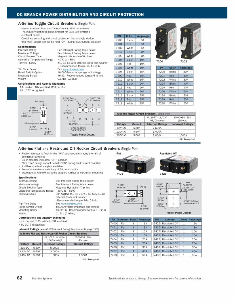
DC BRANCH POWER DISTRIBUTION AND CIRCUIT PROTECTION
Specifi cations subject to change. See www.bluesea.com for current information. Blue Sea Systems 62
A-Series Toggle Circuit Breakers Single Pole
• Meets American Boat and Yacht Council (ABYC) standards
• The industry standard circuit breaker for Blue Sea Systems’
electrical panels
• Combines switching and circuit protection into a single device
• “Trip Free” design cannot be held “ON” during fault current condition
Specifications
Interrupt Rating See Interrupt Rating Table below
Maximum Voltage See Interrupt Rating Table below
Circuit Breaker Type Magnetic Hydraulic—Trip free
Operating Temperature Range -40°C to +85°C
Terminal Screw #10-32 SS with external tooth lock washer
- Recommended torque 14–15 in-lb
Trip Time Delay See www.bluesea.com
Rated Switch Cycles 10,000@rated amperage and voltage
Mounting Screw #6-32 - Recommended torque 6–8 in-lb
Weight 0.17Lb (0.08Kg)
Certifications and Agency Standards
• E marked, TUV certified, CSA certified
• UL 1077 recognized
1 UL Recognized
A-Series Toggle Circuit Breakers - Single Pole
UL 1077 - UL/CSA
(US/Canada)1EN60934 - TUV
(Europe)
Voltage Current Interrupt Ratings Interrupt Ratings
65V DC 5-50A 7,500A -
120V AC 5-50A 3,000A -
250V AC 5-50A 3,000A 1,500AToggle Panel Cutout
7200 7202
PN Color Amperage
7200 Black 5A
7201 Red 5A
7202 White 5A
7347 Black 8A
7299 White 8A
7204 Black 10A
7205 Red 10A
7206 White 10A
7208 Black 15A
7209 Red 15A
7210 White 15A
7212 Black 20A
7213 Red 20A
7214 White 20A
7216 Black 25A
7217 Red 25A
7218 White 25A
1 UL Recognized
Interrupt Ratings (see ABYC Interrupt Rating Requirements page 129)
A-Series Flat and Restricted Off Rocker Circuit Breakers UL 1077 - UL/CSA
(US/Canada)1EN60934 - TUV
(Europe)
Voltage Current Interrupt Ratings Interrupt Ratings
32V DC 5-50A 5,000A -
120V AC 5-50A 3,000A -
240V AC 5-50A 1,500A 1,500A
PN Actuator Poles Amperage
7400 Flat 1 5A
7401 Flat 1 8A
7402 Flat 1 10A
7403 Flat 1 15A
7404 Flat 1 20A
7405 Flat 1 25A
7406 Flat 1 30A
7407 Flat 1 40A
7408 Flat 1 50A
PN Actuator Poles Amperage
7425 Restricted Off 1 5A
7426 Restricted Off 1 8A
7427 Restricted Off 1 10A
7428 Restricted Off 1 15A
7429 Restricted Off 1 20A
7430 Restricted Off 1 25A
7431 Restricted Off 1 30A
7432 Restricted Off 1 40A
7433 Restricted Off 1 50A
Rocker Panel Cutout
• Rocker actuator is fl ush in the “ON” position, eliminating the risk of
accidental switching
• Color actuator indicates “OFF” position
• “Trip Free” design cannot be held “ON” during fault current condition
• 2 different actuator styles available
• Prevents accidental switching of 24 hour circuits
• International ON/OFF symbols support vertical or horizontal mounting
Specifications
Interrupt Rating See Interrupt Rating table below
Maximum Voltage See Interrupt Rating table below
Circuit Breaker Type Magnetic Hydraulic—Trip free
Operating Temperature Range -40°C to +85°C
Terminal Screw 30° Angled #10-32 x 5/16 SS SEM LOAD
external tooth lock washer
- Recommended torque 14–15 in-lb
Trip Time Delay See www.bluesea.com
Rated Switch Cycles 10,000@rated amperage and voltage
Mounting Screw #6-32 SS - Recommended torque 6–8 in-lb
Weight 0.16Lb (0.07Kg)
Certifications and Agency Standards
• E marked, TUV certified, CSA certified
• UL 1077 recognized
A-Series Flat and Restricted Off Rocker Circuit Breakers Single Pole
PN Color Amperage
7220 Black 30A
7221 Red 30A
7222 White 30A
7224 Black 40A
7225 Red 40A
7226 White 40A
7228 Black 50A
7229 Red 50A
7230 White 50A
7403 7425
Restricted OffFlat

DC BRANCH POWER DISTRIBUTION AND CIRCUIT PROTECTION
Specifi cations subject to change. See www.bluesea.com for current information. Catalog 2008
PN Description Weight Lb (Kg)
5015 6 circuit with negative bus 0.55 (0.25)
5018 6 circuit without negative bus 0.48 (0.22)
ST Glass Fuse Blocks (Screw Terminal)
• Clear insulating cover with label recesses accepts
Large Format Labels (page 100)
• Cover satisfies ABYC/USCG insulation requirements
• Tin-plated copper buses and phosphor bronze fuse clips
give 30 Amperes rating per circuit
• Accepts AGC (Fast Acting), MDL (Time-Delay) and all other
3AG Glass Fuses
Specifications
Maximum Voltage 32 Volts DC
Maximum Amperage per circuit 30 Amperes DC
Maximum Amperage per block 100 Amperes DC
Fuse Type AGC/MDL Fuses
Fuse Rating 1/8 to 30 Amperes DC
Screw Terminal #8-32 with Captive Star Lockwasher
Base Material Reinforced Polycarbonate
Cover Material Polycarbonate
Store spare fuses
behind labels
Accepts any 3AG
type glass fuse
Tin-plated phosphor bronze
fuse clips are encapsulated,
cannot be sprung, and
will not injure hands
Integrated
fuse
ejector
lever
Tin-plated
copper
negative
busbar
(5015)
#10-32 stainless
steel stud terminal
Reinforced Polycarbonate base
5015
6 Circuit with Negative Bus
50188
6 Circuit
5015 Dimensions
5018 Dimensions
AGC Fuse
MDL Fuse
63

DC BRANCH POWER DISTRIBUTION AND CIRCUIT PROTECTION
Specifi cations subject to change. See www.bluesea.com for current information. Blue Sea Systems 64
ST Blade Fuse Blocks (Screw Terminal)
• Clear insulating cover with label recesses accepts
Small Format Labels (page 100)
• Cover satisfies ABYC/USCG insulation requirements
• Tin-plated copper buses and fuse clips give 30 Amperes
rating per circuit
• Accepts ATO and ATC fast acting blade fuses (page 65)
• ST Blade Fuse Blocks with covers include 20 write-on
circuit labels
Specifications
Maximum Voltage 32 Volts DC
Maximum Amperage per circuit 30 Amperes DC
Maximum Amperage per block 100 Amperes DC
Fuse Type ATO/ATC Fuses
Fuse Rating 1 to 30 Amperes DC
Screw Terminal #8-32 Screws with Captive
Star Lockwasher
Base Material Reinforced Polycarbonate
Cover Material Polycarbonate
ST Blade Fuse Block Without Cover
PN Description Weight Lb (Kg)
5030 6 circuit with negative bus 0.47 (0.21)
5031 12 circuit with negative bus 0.65 (0.29)
5033 6 circuit 0.42 (0.19)
5034 12 circuit 0.59 (0.27)
See page 65 for ATO/ATC Fuses.
ST Blade Fuse Block With Cover
PN Description Weight Lb (Kg)
5025 6 circuit with negative bus 0.55 (0.25)
5026 12 circuit with negative bus 0.75 (0.34)
5028 6 circuit 0.42 (0.19)
5029 12 circuit 0.68 (0.31)
PN [A] Width in" (mm)[B] Mounting
Centers in" (mm)
[C] Height
in" (mm)
[D] Mounting
Centers in" (mm)
5028/5033 3.315 (84.20) 2.500 (63.50) 3.652 (92.76) 2.639 (67.03)
5025/5030 3.315 (84.20) 2.500 (63.50) 4.894 (124.31) 3.881 (95.58)
5029/5034 3.315 (84.20) 2.500 (63.50) 5.230 (132.84) 4.217 (107.11)
5026/5031 3.315 (84.20) 2.500 (63.50) 6.472 (164.39) 5.459 (138.66)
Accepts ring or
spade type
terminals
Mounts with #8
or M4 screws
Positive distribution
bus with #10-32 studIdentify circuits
with optional labels
Negative
common bus
with #10-32 studStorage
for
spare
fuses
Easy to open,
push button
latch
#8-32 Terminal
screws with
captive lock
washers
5026
5030
5031
5033
5034
5028
50255029
5026
5025
5026

DC BRANCH POWER DISTRIBUTION AND CIRCUIT PROTECTION
Specifi cations subject to change. See www.bluesea.com for current information. Catalog 2008
5006
30 Amp 40 Amp
50 Amp 60 Amp
70 Amp 80 Amp
10 Amp5 Amp
20 Amp 25 Amp 30 Amp
15 Amp
PN Amperage
5235 1A
5236 2A
5237 3A
5238 4A
5239 5A
5240 7.5A
5241 10A
5242 15A
5243 20A
5244 25A
5245 30A
ATO/ATC Fuses • Fast-acting type fuses ideal for electronic devices
• Standard circuit protection device for automobiles and trucks
• Tin-plated connector blades for corrosion resistance
• Visible indication of blown condition
• Sold in packages of 2
Specifications
Interrupt Rating 1,000 Amperes DC
Maximum Voltage 32 Volts DC
Blow Time Delay See www.bluesea.com
Weight per package 0.03Lb (0.01Kg)
See page 64 for ST Blade Fuse Blocks (Screw Terminal)
See page 58 for WeatherDeck™ Waterproof Fuse Panels
MAXI ™ Fuses• Economical
• Tin-plated connector blades for corrosion resistance
• Visible indication of blown condition
• Sold in packages of 2
Specifications
Interrupt Rating 1,000 Amperes DC
Maximum Voltage 32 Volts DC
Blow Time Delay See www.bluesea.com
Weight per package 0.04Lb (0.02Kg)
PN Amperage
5138 30A
5139 40A
5140 50A
5141 60A
5142 70A
5143 80A
See MAXI™ Fuse Block above
65
MAXI ™ Fuse Block• The most economical fuse block for 30–80 Ampere fusing
• Snap-on terminal cover insulates all conductive parts,
satisfying ABYC/USCG requirements
• Accepts wire sizes 18–4 AWG from sides or bottom
• For use on systems up to 32 Volts DC
• Terminal screws compress fuse blades within
blocks for low resistance connections
• Accepts MAXI™ Fuses
Specifications
Maximum Voltage 32 Volts DC
Maximum Amperage 80 Amperes
Fuse Type MAXI™ Fuses
Fuse Rating 30–80 Amperes
Base Material Reinforced Polycarbonate
PN Description Weight Lb (Kg)
5006 30–80A 0.25 (0.11)
See MAXI™ Fuses below
Actual Size Illustrated
Actual Size Illustrated

AC MAIN POWER DISTRIBUTION AND CIRCUIT PROTECTION INTRODUCTION
Specifi cations subject to change. See www.bluesea.com for current information. Blue Sea Systems
AC Main Power Distribution and Circuit ProtectionDefi nitionThe AC Main power system begins at the AC power sources (shore power, genset, or inverter), and ends at the line terminal
connection of the AC branch circuit breaker for the hot wire, and at the branch circuit connection block for the neutral and safety
ground wires.
PurposeAC Main power distribution provides a path for delivering power from the ship’s source of AC power to the AC branch distribution
system. The devices used to distribute AC power are frequently the same as the devices that provide AC circuit protection.
Sources of AC power, whether shore power or on-board generators and inverters, always have a circuit breaker near the power
source. It is designated the AC main circuit breaker.
ConsiderationsIn order to qualify as an AC main circuit breaker, four requirements must be met:
• The circuit breaker must have a suitable AIC rating
• The circuit breaker must be multiple pole, usually double or triple
• The circuit breaker must be rated for the appropriate AC system voltage in which it will be used
• The circuit breaker must be available in amperages appropriate to the design amperage of the system
In the USA, this is generally 30 and 50 Amperes, while European systems are generally 16 and 32 Amperes.
Products in this SectionCircuit Breakers: Circuit breakers used for AC Main circuit protection are double and triple pole, they are available in rocker and
toggle models, and range in continuous current ratings from 10 to 100A. Circuit breaker mounting panels are available.
Power Distribution and Circuit Protection Panels: Blue Sea Systems’ AC Main power distribution panels are available in a variety
of confi gurations. There are Main Only panels in 120V, 120/240V, and 230V (typical of Europe) ratings. There are C-Series Toggle
circuit breaker panels available in 120/240V ratings, and A-Series Toggle available in 120V and 230V (Typical of Europe) ratings.
Panels are available with and without meters, with and without main circuit breakers, and from 1 to 34 positions.
For more information about AC Main Power Distribution and Circuit Protection, refer to pages 131–132 in this catalog.
AC Power Distribution System
AC MainPower DistributionCircuit Protection
AC MainSource Selection
AC BranchPower Distribution
and Circuit Protection
AC PoweredDevicesGenset
Shore Power
66

AC MAIN POWER DISTRIBUTION AND CIRCUIT PROTECTION SECTION INDEX
Specifi cations subject to change. See www.bluesea.com for current information. Catalog 2008 67
Toggle Circuit Breaker Panels Pages 68–69, 73
Double and Triple Pole Circuit Breakers and Mounting Panel Pages 70–73
Page 70
Pages 68–69 Pages 68–69
Page 71
Page 71
Page 72
Page 73
Page 73
Page 72
Page 70
A-Series Toggle, 2 Pole Interrupt Rating: 3,000A AC Maximum Voltage: 250V AC
120 Volt AC Main A-Series Circuit Breaker Panels 230 Volt AC Main A-Series Circuit Breaker Panels (Typical of Europe)
A-Series Flat Rocker, 2 Pole Interrupt Rating: 3,000A AC Maximum Voltage: 240V AC
A-Series Raised Rocker, 2 Pole Interrupt Rating: 3,000A AC Maximum Voltage: 240V AC
C-Series Toggle, 3 Pole Interrupt Rating: 5,000A AC Maximum Voltage: 250V AC
C-Series Flat Rocker, 2 Pole Interrupt Rating: 5,000A AC Maximum Voltage: 240V AC
C-Series Flat Rocker, 3 Pole Interrupt Rating: 5,000A AC Maximum Voltage: 240V AC
C-Series Toggle, 2 Pole Interrupt Rating: 5,000A AC Maximum Voltage: 250V AC
Toggle Circuit Breaker Mounting Panels
10 15 16 20 30 32 40 50
10 15 16 20 30 32 40 50
30 50 60 80 100
50 60 80 100
30 50 60 80 100
200 AmperesAC Current Ratings (Amperes)0 AmperesAC Current Ratings
Page 73
120/240 Volt AC C-Series Toggle Circuit Breaker Panels
Page 73
C-Series Raised Rocker, 2 Pole Interrupt Rating: 5,000A AC Maximum Voltage: 240V AC
Page 73
C-Series Raised Rocker, 3 Pole Interrupt Rating: 5,000A AC Maximum Voltage: 240V AC
50 60 80 100
See page 17 for a full selection of related products locatedin the new 360 Panel System section of this catalog.
30 50 60 80 100
10 15 16 20 30 32 40 50
50 60 80 100
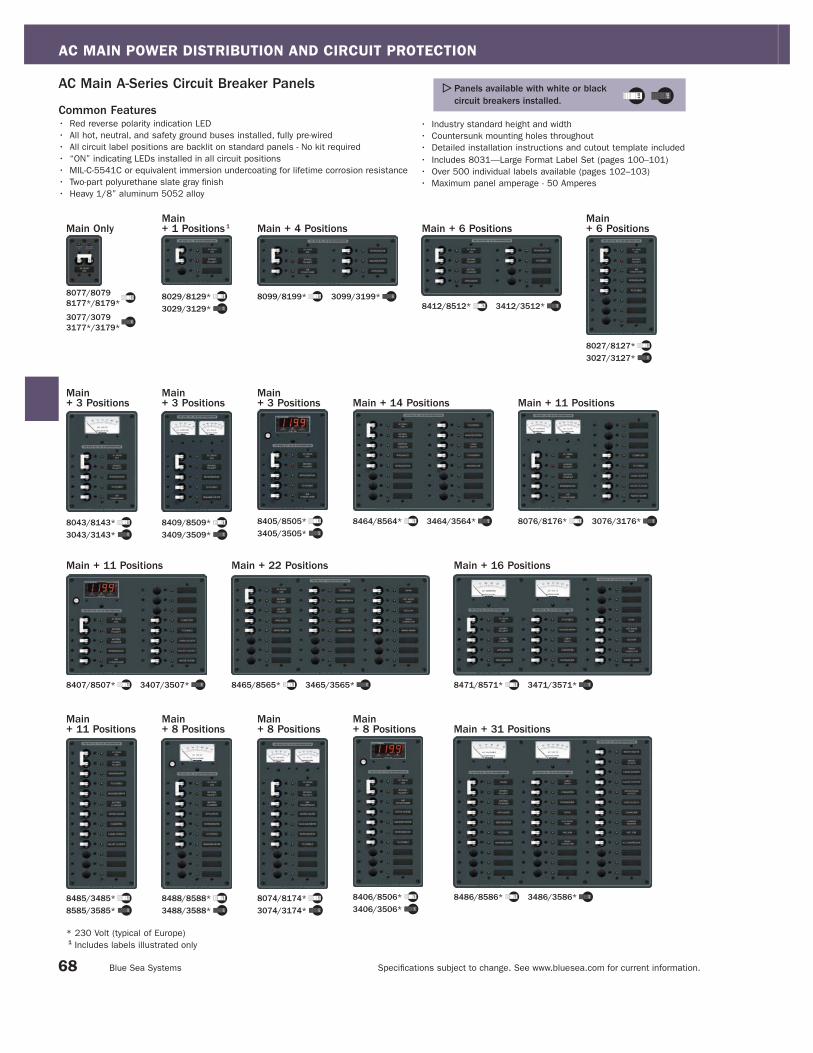
AC MAIN POWER DISTRIBUTION AND CIRCUIT PROTECTION
Specifi cations subject to change. See www.bluesea.com for current information. Blue Sea Systems
Main + 31 Positions
8486/8586* 3486/3586*
Main + 11 Positions
8076/8176* 3076/3176*
Main + 22 Positions
8465/8565* 3465/3565*
Main + 11 Positions
8407/8507* 3407/3507*
Main + 16 Positions
8471/8571* 3471/3571*
Main + 14 Positions
8464/8564* 3464/3564*
* 230 Volt (typical of Europe)1 Includes labels illustrated only
8406/8506*3406/3506*
Main+ 8 Positions
8074/8174*3074/3174*
Main+ 8 Positions
8488/8588*3488/3588*
Main+ 8 Positions
8485/3485*8585/3585*
Main+ 11 Positions
8405/8505*3405/3505*
Main+ 3 Positions
8043/8143*3043/3143*
Main+ 3 Positions
8409/8509*3409/3509*
Main+ 3 Positions
8027/8127*3027/3127*
Main+ 6 PositionsMain + 6 Positions
8412/8512* 3412/3512*
Main + 4 Positions
8099/8199* 3099/3199*8029/8129*3029/3129*
Main+ 1 Positions 1
Common Features• Red reverse polarity indication LED
• All hot, neutral, and safety ground buses installed, fully pre-wired
• All circuit label positions are backlit on standard panels - No kit required
• “ON” indicating LEDs installed in all circuit positions
• MIL-C-5541C or equivalent immersion undercoating for lifetime corrosion resistance
• Two-part polyurethane slate gray fi nish
• Heavy 1/8” aluminum 5052 alloy
• Industry standard height and width
• Countersunk mounting holes throughout
• Detailed installation instructions and cutout template included
• Includes 8031—Large Format Label Set (pages 100–101)
• Over 500 individual labels available (pages 102–103)
• Maximum panel amperage - 50 Amperes
AC Main A-Series Circuit Breaker Panels Panels available with white or black circuit breakers installed.
68
Main Only
8077/80798177*/8179*
3077/30793177*/3179*

AC MAIN POWER DISTRIBUTION AND CIRCUIT PROTECTION
Specifi cations subject to change. See www.bluesea.com for current information. Catalog 2008
230 Volt Main A-Series Toggle Circuit Breaker Panels (Typical of Europe)
PN PNDescription Meter/PN
Meter
PageWidth in" (mm) Height in" (mm) Weight Lb (Kg)
Installed Double Pole
Circuit Breakers
Installed Single Pole
Circuit Breaker
16A 32A 8A
8129 3129 Main + 1 Position - - 5.25 (133.35) 3.75 (95.25) 1.05 (0.48) 1 - -
8143 3143 Main + 3 Positions Analog/9354 111 5.25 (133.35) 7.50 (190.50) 2.00 (0.91) 1 - 3
8509 3509 Main + 3 Positions Analog/8246, 8245 111 5.25 (133.35) 7.50 (190.50) 4.06 (1.84) 1 - 3
8505 3505 Main + 3 Positions Digital/8247 107 5.25 (133.35) 7.50 (190.50) 2.94 (1.33) 1 - 3
8199 3199 Main + 4 Positions - - 10.50 (266.70) 3.75 (95.25) 2.22 (1.00) 1 - 4
8127 3127 Main + 6 Positions - - 5.25 (133.35) 7.50 (190.50) 2.00 (0.91) 1 - 3
8512 3512 Main + 6 Positions - - 10.50 (266.70) 4.50 (114.30) 1.90 (0.86) 1 - 4
8588 3588 Main + 8 Positions Analog/9354 111 5.25 (133.35) 11.25 (285.75) 3.00 (1.36) 1 - 5
8174 3174 Main + 8 Positions Analog/8246, 8245 107 5.25 (133.35) 11.25 (285.75) 3.28 (1.49) 1 - 5
8506 3506 Main + 8 Positions Digital/8247 107 5.25 (133.35) 11.25 (285.75) 3.18 (1.44) 1 - 5
8176 3176 Main + 11 Positions Analog/8246, 8245 111 10.50 (266.70) 7.50 (190.50) 4.24 (1.92) 1 - 8
8507 3507 Main + 11 Positions Digital/8247 107 10.50 (266.70) 7.50 (190.50) 4.78 (2.17) 1 - 8
8585 3585 Main + 11 Positions - - 5.25 (133.35) 11.25 (285.75) 2.81 (1.27) 1 - 8
8564 3564 Main + 14 Positions - - 10.50 (266.70) 7.50 (190.50) 3.74 (1.70) 1 - 8
8571 3571 Main + 16 Positions Analog/9354, 9630 111 14.75 (374.65) 7.50 (190.50) 5.96 (2.70) 1 - 13
8565 3565 Main + 22 Positions - - 14.75 (374.65) 7.50 (190.50) 5.25 (2.38) 1 - 13
8586 3586 Main + 31 Positions Analog/9354, 9630 111 14.75 (374.65) 11.25 (285.75) 8.94 (4.05) 1 - 22
120 Volt Main A-Series Toggle Circuit Breaker Panels
PN PNDescription Meter Type/PN
Meter
PageWidth in" (mm) Height in" (mm) Weight Lb (Kg)
Installed Double Pole
Circuit Breakers
Installed Single Pole
Circuit Breakers
30A 50A 15A
8029 3029 Main + 1 Position - - 5.25 (133.35) 3.75 (95.25) 1.05 (0.48) 1 - -
8043 3043 Main + 3 Positions Analog/9353 111 5.25 (133.35) 7.50 (190.50) 2.00 (0.91) 1 - 3
8409 3409 Main + 3 Positions Analog/8246, 8244 111 5.25 (133.35) 7.50 (190.50) 4.06 (1.84) 1 - 3
8405 3405 Main + 3 Positions Digital/8247 107 5.25 (133.35) 7.50 (190.50) 2.94 (1.33) 1 - 3
8099 3099 Main + 4 Positions - - 10.50 (266.70) 3.75 (95.25) 2.22 (1.00) 1 - 4
8027 3027 Main + 6 Positions - - 5.25 (133.35) 7.50 (190.50) 2.00 (0.91) 1 - 3
8412 3412 Main + 6 Positions - - 10.50 (266.70) 4.50 (114.30) 1.90 (0.86) 1 - 4
8488 3488 Main + 8 Positions Analog/9353 111 5.25 (133.35) 11.25 (285.75) 3.00 (1.36) 1 - 5
8074 3074 Main + 8 Positions Analog/8244, 8246 111 5.25 (133.35) 11.25 (285.75) 3.28 (1.49) 1 - 5
8406 3406 Main + 8 Positions Digital/8247 107 5.25 (133.35) 11.25 (285.75) 3.18 (1.44) 1 - 5
8076 3076 Main + 11 Positions Analog/8244, 8246 111 10.50 (266.70) 7.50 (190.50) 4.24 (1.92) 1 - 8
8407 3407 Main + 11 Positions Digital/8247 107 10.50 (266.70) 7.50 (190.50) 4.78 (2.17) 1 - 8
8485 3485 Main + 11 Positions - - 5.25 (133.35) 11.25 (285.75) 2.81 (1.27) 1 - 8
8464 3464 Main + 14 Positions - - 10.50 (266.70) 7.50 (190.50) 3.74 (1.70) 1 - 8
8471 3471 Main + 16 Positions Analog/9630, 9353 111 14.75 (374.65) 7.50 (190.50) 5.96 (2.70) 1 - 13
8465 3465 Main + 22 Positions - - 14.75 (374.65) 7.50 (190.50) 5.25 (2.38) 1 - 13
8486 3486 Main + 31 Positions Analog/9630, 9353 111 14.75 (374.65) 11.25 (285.75) 8.94 (4.05) 1 - 22
Use the tables below to select AC Distribution Panels with AC Main Circuit Breakers where a single AC electrical source is brought to the panel and AC Main Circuit Protection is desired.
69
230 Volt Main Only A-Series Toggle Circuit Breaker Panels (Typical of Europe)
PN PNDescription Meter/PN
Meter
PageWidth in" (mm) Height in" (mm) Weight Lb (Kg)
Installed Double Pole
Circuit Breakers
16A 30A 32A 50A
8177 3177 Main Only - - 2.63 (66.80) 3.75 (95.25) 3.75 (95.25) 1 - - -
8179 3179 Main Only - - 2.63 (66.80) 3.75 (95.25) 3.75 (95.25) 1 - 1 -
120 Volt Main Only A-Series Toggle Circuit Breaker Panels
PN PNDescription Meter Type/PN
Meter
PageWidth in" (mm) Height in" (mm) Weight Lb (Kg)
Installed Double Pole
Circuit Breakers
16A 30A 32A 50A
8077 3077 Main Only - - 2.63 (66.80) 3.75 (95.25) 3.75 (95.25) - 1 -
8079 3079 Main Only - - 2.63 (66.80) 3.75 (95.25) 3.75 (95.25) - - - 1
See page 17 for a full selection of related products located in the new 360 Panel System section of this catalog.

AC MAIN POWER DISTRIBUTION AND CIRCUIT PROTECTION
Specifi cations subject to change. See www.bluesea.com for current information. Blue Sea Systems
Panel Cutout
7233
• Meets American Boat and Yacht Council (ABYC) standards
• The industry standard circuit breaker for Blue Sea Systems electrical panels
• Combines switching and circuit protection into a single device
• Used as AC main circuit protection
• “Trip Free” design cannot be held “ON” during fault current condition
• For circuit breaker mounting panel 8173 (see below)
Specifications
Interrupt Rating See Interrupt Rating Table below
Maximum Voltage See Interrupt Rating Table below
Circuit Breaker Type Magnetic Hydraulic - Trip free
Operating Temperature Range -40°C to +85°C
Terminal Screw #10-32 SS with external tooth lockwasher
- Recommended torque 14-15 in-lb
Trip Time Delay See www.bluesea.com
Rated Switch Cycles 10,000 @ rated amperage and voltage
Mounting Screw #6-32 SS - Recommended torque 6-8 in-lb
Weight 0.30Lb (0.14Kg)
Certifications and Agency Standards
• E marked, TUV certified, CSA certified
• UL 1077 recognized
A-Series Toggle Circuit Breakers Double Pole
1 UL Recognized
Interrupt Ratings (see ABYC Interrupt Rating Requirements page 129)
A-Series Toggle Circuit Breakers - Double Pole
UL 1077 - UL/CSA
(US/Canada)1EN60934 - TUV
(Europe)
Voltage Current Interrupt Ratings Interrupt Ratings
65V DC 10-50A 7,500A -
120V AC 10-50A 3,000A -
120/240V AC 10-50A 3,000A -
250V AC 10-50A 3,000A 1,500A
PN Color Amperage
7232 Black 10A
7233 White 10A
7234 Black 15A
7235 White 15A
7348 Black 16A
7294 White 16A
7236 Black 20A
7260 White 20A
PN Color Amperage
7237 Black 30A
7238 White 30A
7349 Black 32A
7295 White 32A
7239 Black 40A
7240 White 40A
7241 Black 50A
7242 White 50A
PN Description Weight Lb (Kg)
8173 Mounting Panel - Double Pole 0.08 (0.04) 8173
A-Series Toggle Circuit Breaker Mounting Panel Double Pole• Mounts A-Series Double Pole Toggle Circuit Breakers (see above)
• Slate gray matches standard panel color
Specifications
Panel Material: Heavy 1/8" aluminum 5052 alloy
Primary Finish: Mil-C-5541C or equivalent immersion undercoating for
lifetime corrosion resistance
Final Panel Finish: 2-part polyurethane slate gray fi nish
Dimensions 2.63" (66.80mm) x 3.75" (95.25mm)
70

AC MAIN POWER DISTRIBUTION AND CIRCUIT PROTECTION
Specifi cations subject to change. See www.bluesea.com for current information. Catalog 2008
Cutout Dimensions
PN Actuator Poles Amperage Weight Lb (Kg)
7570 Raised 2 10A 0.38 (0.17)
7571 Raised 2 15A 0.38 (0.17)
7572 Raised 2 16A 0.38 (0.17)
7573 Raised 2 20A 0.38 (0.17)
7574 Raised 2 30A 0.38 (0.17)
7575 Raised 2 32A 0.38 (0.17)
7576 Raised 2 40A 0.38 (0.17)
7577 Raised 2 50A 0.38 (0.17)
A-Series Raised and Flat Rocker Circuit Breakers Double Pole
• Color actuator indicates “OFF” position
• “Trip Free” design cannot be held “ON” during fault current condition
• 2 different styles available
• International ON/OFF symbols support vertical or horizontal mounting
Specifications
Interrupt Rating See Interrupt Rating table below
Maximum Voltage See Interrupt Rating table below
Circuit Breaker Type Magnetic Hydraulic - Trip free
Operating Temperature Range -40°C to +85°C
Terminal Screw 30° Angled #10-32 x 5/16 SS SEM LOAD
external tooth lock washer
- Recommended torque 14-15 in-lb trip time delay
See www.bluesea.com
Rated Switch Cycles 10,000@rated amperage and voltage
Mounting Screw #6-32 SS - Recommended torque 6-8 in-lb
Certifications and Agency Standards
• E marked, TUV certified, CSA certified
• UL 1077 recognized
71
PN Actuator Poles Amperage Weight Lb (Kg)
7410 Flat 2 10A 0.38 (0.17)
7411 Flat 2 15A 0.38 (0.17)
7412 Flat 2 16A 0.38 (0.17)
7413 Flat 2 20A 0.38 (0.17)
7414 Flat 2 30A 0.38 (0.17)
7415 Flat 2 32A 0.38 (0.17)
7416 Flat 2 40A 0.38 (0.17)
7417 Flat 2 50A 0.38 (0.17)
NEW PRODUCT
7574
7414
7574
7414
1 UL Recognized
Interrupt Ratings (see ABYC Interrupt Rating Requirements page 129)
A-Series Raised and Flat Rocker Circuit Breakers UL 1077 - UL/CSA
(US/Canada)1EN60934 - TUV
(Europe)
Voltage Current Interrupt Ratings Interrupt Ratings
32V DC 10-50A 5,000A -
120/240V AC 10-50A 3,000A -
240V AC 10-50A 3,000A 1,500A
RAMPAGE 33 EXPRESS - Rampage Sport Fishing Yachts
Raised
Flat
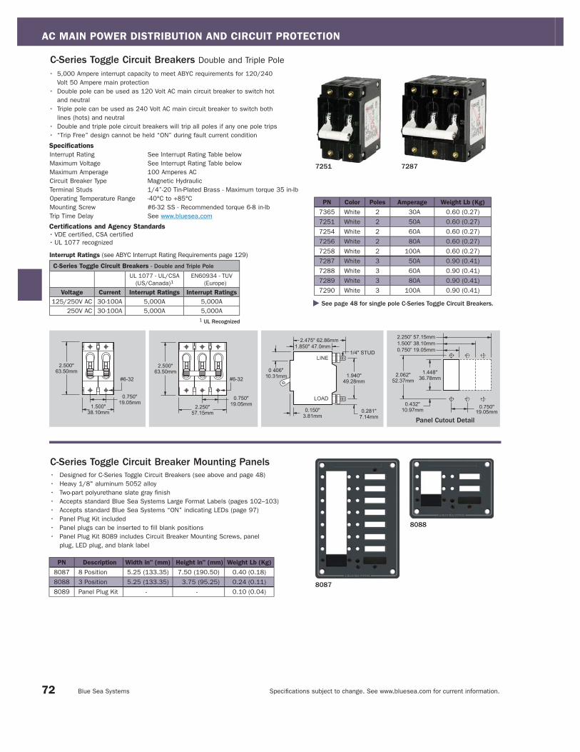
AC MAIN POWER DISTRIBUTION AND CIRCUIT PROTECTION
Specifi cations subject to change. See www.bluesea.com for current information. Blue Sea Systems
8087
8088
C-Series Toggle Circuit Breakers Double and Triple Pole
1 UL Recognized
Interrupt Ratings (see ABYC Interrupt Rating Requirements page 129)
C-Series Toggle Circuit Breakers - Double and Triple Pole
UL 1077 - UL/CSA
(US/Canada)1EN60934 - TUV
(Europe)
Voltage Current Interrupt Ratings Interrupt Ratings
125/250V AC 30-100A 5,000A 5,000A
250V AC 30-100A 5,000A 5,000A
See page 48 for single pole C-Series Toggle Circuit Breakers.
7251 7287
PN Color Poles Amperage Weight Lb (Kg)
7365 White 2 30A 0.60 (0.27)
7251 White 2 50A 0.60 (0.27)
7254 White 2 60A 0.60 (0.27)
7256 White 2 80A 0.60 (0.27)
7258 White 2 100A 0.60 (0.27)
7287 White 3 50A 0.90 (0.41)
7288 White 3 60A 0.90 (0.41)
7289 White 3 80A 0.90 (0.41)
7290 White 3 100A 0.90 (0.41)
PN Description Width in" (mm) Height in" (mm) Weight Lb (Kg)
8087 8 Position 5.25 (133.35) 7.50 (190.50) 0.40 (0.18)
8088 3 Position 5.25 (133.35) 3.75 (95.25) 0.24 (0.11)
8089 Panel Plug Kit - - 0.10 (0.04)
C-Series Toggle Circuit Breaker Mounting Panels• Designed for C-Series Toggle Circuit Breakers (see above and page 48)
• Heavy 1/8" aluminum 5052 alloy
• Two-part polyurethane slate gray finish
• Accepts standard Blue Sea Systems Large Format Labels (pages 102–103)
• Accepts standard Blue Sea Systems “ON” indicating LEDs (page 97)
• Panel Plug Kit included
• Panel plugs can be inserted to fill blank positions
• Panel Plug Kit 8089 includes Circuit Breaker Mounting Screws, panel
plug, LED plug, and blank label
Panel Cutout Detail
• 5,000 Ampere interrupt capacity to meet ABYC requirements for 120/240
Volt 50 Ampere main protection
• Double pole can be used as 120 Volt AC main circuit breaker to switch hot
and neutral
• Triple pole can be used as 240 Volt AC main circuit breaker to switch both
lines (hots) and neutral
• Double and triple pole circuit breakers will trip all poles if any one pole trips
• “Trip Free” design cannot be held “ON” during fault current condition
Specifications
Interrupt Rating See Interrupt Rating Table below
Maximum Voltage See Interrupt Rating Table below
Maximum Amperage 100 Amperes AC
Circuit Breaker Type Magnetic Hydraulic
Terminal Studs 1/4”-20 Tin-Plated Brass - Maximum torque 35 in-lb
Operating Temperature Range -40°C to +85°C
Mounting Screw #6-32 SS - Recommended torque 6-8 in-lb
Trip Time Delay See www.bluesea.com
Certifications and Agency Standards
• VDE certified, CSA certified
• UL 1077 recognized
72

AC MAIN POWER DISTRIBUTION AND CIRCUIT PROTECTION
Specifi cations subject to change. See www.bluesea.com for current information. Catalog 2008
Cutout Dimensions
120/240 Volt AC C-Series Toggle Circuit Breaker Panels• Red reverse polarity indicating LED
• All neutral and safety ground buses installed
• Label backlighting pre-installed
• All LEDs installed
• Extra positions available for double pole A-Series Toggle Circuit Breakers (page 72)
• Maximum panel amperage - 50 Amperes
120/240 Volt AC Main C-Series Toggle Circuit Breaker Panels
PN DescriptionMeter Type
PN
Meter
Page
Width in"
(mm)
Height in"
(mm)
Weight Lb
(Kg)
Installed
C-Series
Toggle
3 Pole Main
50A
7370Main+ 3 Positions
Analog Volt
9354111
5.25
(133.35)
11.25
(285.75)
2.98
(1.35)1
7371Main+ 3 Positions
Digital Multimeter
8247107
5.25
(133.35)
11.25
(285.75)
3.37
(1.53)1
7372 Main Only - -5.25
(133.35)
3.75
(95.25)
1.38
(0.63)1
Main Only
7372
Main + 3 Positions
7370
Main + 3 Positions
7371
Blue Sea Systems recommends using double pole circuit breakers to fi ll blank positions.
73
C-Series Raised and Flat Rocker Circuit Breakers Double and Triple Pole
1 UL Recognized
Interrupt Ratings (see ABYC Interrupt Rating Requirements page 129)
C-Series Toggle Circuit Breakers - Double and Triple Pole
UL 1077 - UL/CSA
(US/Canada)1EN60934 - TUV
(Europe)
Voltage Current Interrupt Ratings Interrupt Ratings
125/240V AC 30-100A 5,000A -
240V AC 30-100A - 5,000A
See page 49 for single pole C-Series Rocker Circuit Breakers
PN Actuator Poles Amperage
7580 Raised 2 30A
7581 Raised 2 50A
7582 Raised 2 60A
7583 Raised 2 80A
7584 Raised 2 100A
7585 Raised 3 50A
7586 Raised 3 60A
7587 Raised 3 80A
7588 Raised 3 100A
• 5,000 Ampere interrupt capacity to meet ABYC requirements for 120/240 Volt
50 Ampere main protection
• Double pole can be used as 120 Volt AC main circuit breaker to switch hot and
neutral
• Triple pole can be used as 240 Volt AC main circuit breaker to switch both
lines (hots) and neutral
• Double and triple pole circuit breakers will trip all poles if any one pole trips
• “Trip Free” design cannot be held “ON” during fault current condition
Specifications
Interrupt Rating See Interrupt Rating Table below
Maximum Voltage See Interrupt Rating Table below
Maximum Amperage 100 Amperes AC
Circuit Breaker Type Magnetic
Terminal Studs 1/4”-20 Tin-Plated Brass
- Maximum torque 35 in-lb
Operating Temperature Range -40°C to +85°C
Mounting Screw #6-32 SS
- Recommended torque 6-8 in-lb
Trip Time Delay See www.bluesea.com
Certifications and Agency Standards
• TUV certified, CSA certified
• UL 1077 recognized
PN Actuator Poles Amperage
7560 Flat 2 30A
7561 Flat 2 50A
7562 Flat 2 60A
7563 Flat 2 80A
7564 Flat 2 100A
7565 Flat 3 50A
7566 Flat 3 60A
7567 Flat 3 80A
7568 Flat 3 100A
7580 75687580 7568
NEW PRODUCT
Double and Triple Pole
Raised
Flat

AC MAIN SOURCE SELECTION INTRODUCTION
Specifi cations subject to change. See www.bluesea.com for current information. Blue Sea Systems
AC Main Source SelectionDefi nitionSource selection devices select between two or more sources of AC power and allow only one AC source to be connected at a
time.
PurposeAC sources from shore power, gensets, inverters, and isolation transformers must be switched in such a way that ensures only
one AC source is connected and all other AC sources are completely disconnected. A properly designed selector system will
allow only the appropriate neutral and hot source conductors to connect to the load without allowing the system to supply power
backwards to unused connections or sources.
Products in this SectionIn marine AC systems, there are two common methods used to switch AC sources—circuit breaker panels with lockout slides
and rotary switches. AC Lockout Slides are devices that slide between circuit breaker handles and allow only one handle to be
in the ON position, allowing only one source of AC power at a time. AC Rotary Switches use a switching mechanism to prevent
connection of different sources at the same time.
Circuit Breaker Panels: Blue Sea Systems’ AC Main source selection panels are available for 120V, 120/240V, and 230V (typical
of Europe) ratings, with toggle style circuit breakers. They are available with and without meters, switch 2 and 3 sources, and have
from 2 to 32 positions. Often, AC Main circuit protection, source selection, and branch circuit protection are combined in
one panel.
Rotary Switch Panels: Blue Sea Systems’ AC Main source selection rotary switches are available in 120V, 120/240V, and 230V
(typical of Europe) ratings.
For more information about AC main source selection, refer to pages 133 in this catalog.
AC MainPower DistributionCircuit Protection
AC MainSource Selection
AC BranchPower Distribution
and Circuit Protection
ON ON
AC PoweredDevicesGenset
Shore Power
74
AC Power Distribution System

AC MAIN SOURCE SELECTION SECTION INDEX
Specifi cations subject to change. See www.bluesea.com for current information. Catalog 2008 75
120/240 Volt Source Selection Toggle Circuit Breaker Panels Page 78
Source Selection Rotary Switches and Panels Pages 79–81
A-Series Source Selection Toggle Circuit Breaker Panels Pages 76–77
Pages 76–77
Page 78
Pages 76–77
120 Volt A-Series Source Selection Circuit Breaker Panels
120/240 Volt, C-Series Source Selection Circuit Breaker Panels
230 Volt A-Series Source Selection Circuit Breaker Panels(Typical of Europe)
Rotary Switch and Panels 65 Ampere 2 Positions + OFF, 2 Pole
Maximum Amperage: 65 Amperes AC
Rotary Switch and Panel65 Ampere 2 Positions + OFF, 3 Pole
Maximum Amperage: 65 Amperes AC
Rotary Switch and Panels32 Ampere 3 Positions + OFF, 2 Pole
Maximum Amperage: 32 Amperes AC
Rotary Switches and Panels30 or 65 Ampere 2 Positions + OFF, 4 Pole
Maximum Amperage: 30 and 65 Amperes AC
Rotary Switch and Panel65 Ampere 3 Positions + OFF, 3 Pole
Maximum Amperage: 65 Amperes AC
Rotary Switch and Panels 32 Ampere 2 Positions + OFF, 2 Pole
Maximum Amperage: 32 Amperes AC
See pages 18–19 for a full selection of related products locatedin the new 360 Panel System section of this catalog.
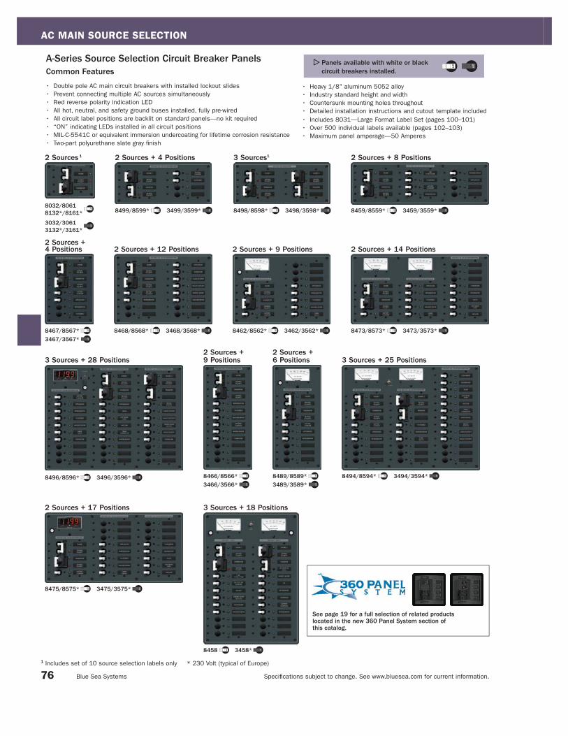
AC MAIN SOURCE SELECTION
Specifi cations subject to change. See www.bluesea.com for current information. Blue Sea Systems
2 Sources + 4 Positions
8499/8599* 3499/3599*
3 Sources1
8498/8598* 3498/3598*
2 Sources + 8 Positions
8459/8559* 3459/3559*
3 Sources + 28 Positions
8496/8596* 3496/3596*
3 Sources + 25 Positions
8494/8594* 3494/3594*
2 Sources +6 Positions
8489/8589*3489/3589*
2 Sources + 17 Positions
8475/8575* 3475/3575*
2 Sources +9 Positions
8466/8566*3466/3566*
8458 3458*
3 Sources + 18 Positions
1 Includes set of 10 source selection labels only * 230 Volt (typical of Europe)
2 Sources + 9 Positions
8462/8562* 3462/3562*
2 Sources + 14 Positions
8473/8573* 3473/3573*
2 Sources + 12 Positions
8468/8568* 3468/3568*
2 Sources + 4 Positions
8467/8567*3467/3567*
2 Sources 1
8032/80618132*/8161*
3032/30613132*/3161*
• Double pole AC main circuit breakers with installed lockout slides
• Prevent connecting multiple AC sources simultaneously
• Red reverse polarity indication LED
• All hot, neutral, and safety ground buses installed, fully pre-wired
• All circuit label positions are backlit on standard panels—no kit required
• “ON” indicating LEDs installed in all circuit positions
• MIL-C-5541C or equivalent immersion undercoating for lifetime corrosion resistance
• Two-part polyurethane slate gray fi nish
• Heavy 1/8" aluminum 5052 alloy
• Industry standard height and width
• Countersunk mounting holes throughout
• Detailed installation instructions and cutout template included
• Includes 8031—Large Format Label Set (pages 100–101)
• Over 500 individual labels available (pages 102–103)
• Maximum panel amperage—50 Amperes
A-Series Source Selection Circuit Breaker PanelsCommon Features
Panels available with white or black circuit breakers installed.
76
See page 19 for a full selection of related products located in the new 360 Panel System section of this catalog.

AC MAIN SOURCE SELECTION
Specifi cations subject to change. See www.bluesea.com for current information. Catalog 2008
230 Volt A-Series Source Selection Toggle Circuit Breaker Panels (Typical of Europe)
PN PNDescription Meter Type/PN
Meter
PageWidth in" (mm) Height in" (mm) Weight Lb (Kg)
Installed
Double Pole
Circuit Breakers
Installed
Single Pole
Circuit Breakers
16A 32A 8A
8132 3132 2 Sources - - 5.25 (133.35) 3.75 (95.25) 1.35 (0.61) 2 - -
8161 3161 2 Sources - - 5.25 (133.35) 3.75 (95.25) 1.84 (0.83) - 2 -
8598 3598 3 Sources - - 10.50 (266.70) 4.50 (114.30) 1.90 (0.86) 3 1 -
8567 3567 2 Sources + 4 Positions - - 5.25 (133.35) 7.50 (190.50) 2.15 (0.98) 2 - 2
8599 3599 2 Sources + 4 Positions - - 10.50 (266.70) 4.50 (114.30) 1.90 (0.86) 2 - 2
8589 3589 2 Sources + 6 Positions Volt/9354 111 5.25 (133.35) 11.25 (285.75) 3.00 (1.36) 2 - 3
8559 3559 2 Sources + 8 Positions - - 14.75 (374.65) 4.50 (114.30) 3.15 (1.43) 2 - 6
8566 3566 2 Sources + 9 Positions - - 5.25 (133.35) 11.25 (285.75) 2.81 (1.27) 2 - 6
8562 3562 2 Sources + 9 Positions Volt/9354 111 10.50 (266.70) 7.50 (190.50) 3.80 (1.72) 2 - 6
8568 3568 2 Sources + 12 Positions - - 10.50 (266.70) 7.50 (190.50) 3.75 (1.70) 2 - 8
8573 3573 2 Sources + 14 Positions Volt, Amp/9354, 9630 111 14.75 (374.65) 7.50 (190.50) 6.00 (2.72) 2 - 11
8575 3575 2 Sources + 17 Positions Multimeter/8247 107 14.75 (374.65) 7.50 (190.50) 5.30 (2.40) 2 - 11
8594 3594 3 Sources + 25 Positions Volt, Amp/9354, 9630 111 14.75 (374.65) 11.25 (285.75) 9.00 (4.08) 3 1 16
8596 3596 3 Sources + 28 Positions Multimeter/8247 107 14.75 (374.65) 11.25 (285.75) 10.10 (4.58) 3 1 19
120 Volt A-Series Source Selection Toggle Circuit Breaker Panels
PN PNDescription Meter Type/PN
Meter
PageWidth in" (mm) Height in" (mm) Weight Lb (Kg)
Installed
Double Pole
Circuit Breakers
Installed
Single Pole
Circuit Breakers
30A 50A 15A
8032 3032 2 Sources - - 5.25 (133.35) 3.75 (95.25) 1.35 (0.61) 2 - -
8061 3061 2 Sources - - 5.25 (133.35) 3.75 (95.25) 1.84 (0.83) - 2 -
8498 3498 3 Sources - - 10.50 (266.70) 4.50 (114.30) 1.90 (0.86) 3 1 -
8467 3467 2 Sources + 4 Positions - - 5.25 (133.35) 7.50 (190.50) 2.15 (0.98) 2 - 2
8499 3499 2 Sources + 4 Positions - - 10.50 (266.70) 4.50 (114.30) 1.90 (0.86) 2 - 2
8489 3489 2 Sources + 6 Positions Volt/9353 111 5.25 (133.35) 11.25 (285.75) 3.00 (1.36) 2 - 3
8459 3459 2 Sources + 8 Positions - - 14.75 (374.65) 4.50 (114.30) 3.15 (1.43) 2 - 6
8466 3466 2 Sources + 9 Positions - - 5.25 (133.35) 11.25 (285.75) 2.81 (1.27) 2 - 6
8462 3462 2 Sources + 9 Positions Volt/9353 111 10.50 (266.70) 7.50 (190.50) 3.80 (1.72) 2 - 6
8468 3468 2 Sources + 12 Positions - - 10.50 (266.70) 7.50 (190.50) 3.75 (1.70) 2 - 8
8473 3473 2 Sources + 14 Positions Volt, Amp/9353, 9630 111 14.75 (374.65) 7.50 (190.50) 6.00 (2.72) 2 - 11
8475 3475 2 Sources + 17 Positions Multimeter/8247 107 14.75 (374.65) 7.50 (190.50) 5.30 (2.40) 2 - 11
8458 3458 3 Sources + 18 Positions Volt, Amp/9353, 9630 111 10.50 (266.70) 13.75 (349.25) 9.10 (4.12) 3 1 12
8494 3494 3 Sources + 25 Positions Volt, Amp/9353, 9630 111 14.75 (374.65) 11.25 (285.75) 9.00 (4.08) 3 1 16
8496 3496 3 Sources + 28 Positions Multimeter/8247 107 14.75 (374.65) 11.25 (285.75) 10.10 (4.58) 3 1 19
Use the tables below to select AC Distribution Panels with AC Source Selectors where multiple sources must be managed on the panel.
77
Photo Courtesy of Hanse Yachts
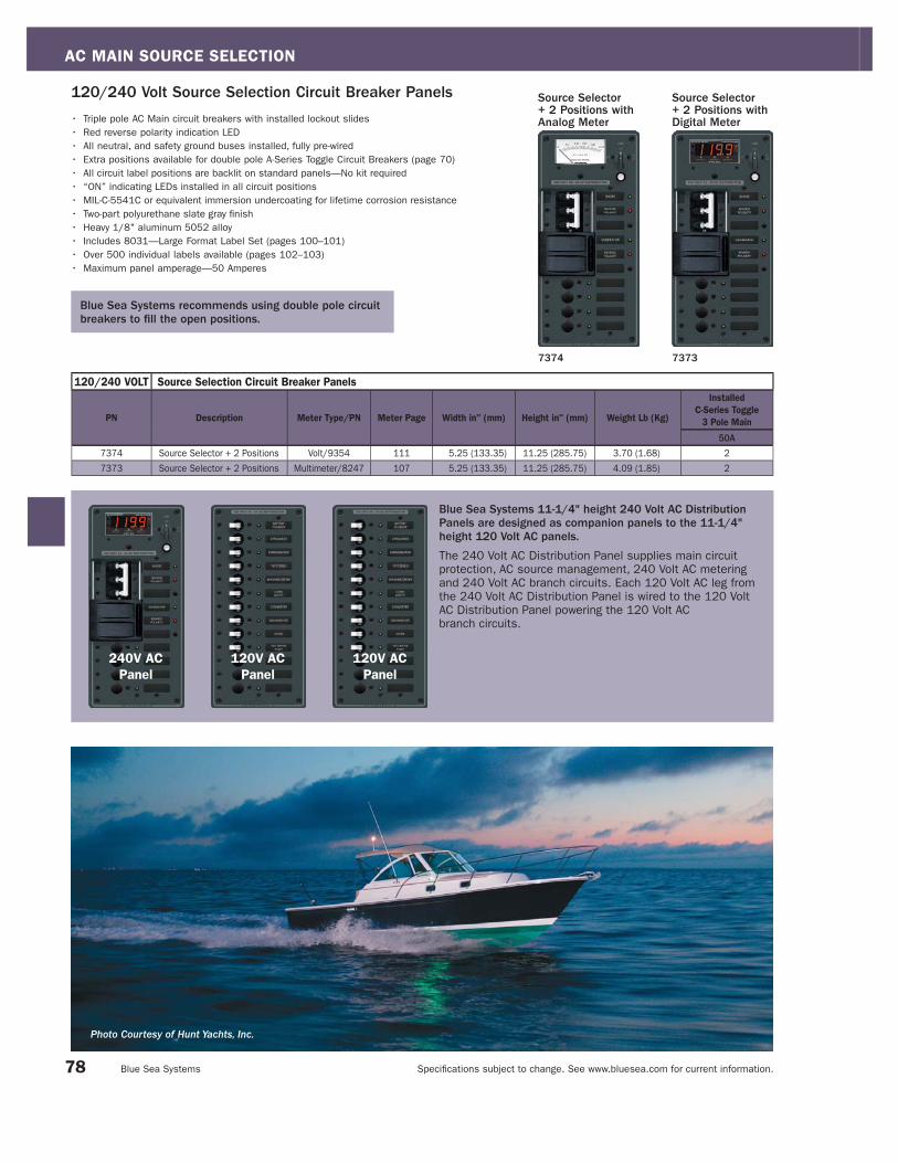
AC MAIN SOURCE SELECTION
Specifi cations subject to change. See www.bluesea.com for current information. Blue Sea Systems
120/240 VOLT Source Selection Circuit Breaker Panels
PN Description Meter Type/PN Meter Page Width in" (mm) Height in" (mm) Weight Lb (Kg)
Installed
C-Series Toggle
3 Pole Main
50A
7374 Source Selector + 2 Positions Volt/9354 111 5.25 (133.35) 11.25 (285.75) 3.70 (1.68) 2
7373 Source Selector + 2 Positions Multimeter/8247 107 5.25 (133.35) 11.25 (285.75) 4.09 (1.85) 2
Blue Sea Systems 11-1/4" height 240 Volt AC Distribution Panels are designed as companion panels to the 11-1/4" height 120 Volt AC panels.
The 240 Volt AC Distribution Panel supplies main circuit
protection, AC source management, 240 Volt AC metering
and 240 Volt AC branch circuits. Each 120 Volt AC leg from
the 240 Volt AC Distribution Panel is wired to the 120 Volt
AC Distribution Panel powering the 120 Volt AC
branch circuits.
240V AC
Panel
120V AC
Panel
120V AC
Panel
120/240 Volt Source Selection Circuit Breaker Panels Source Selector + 2 Positions withDigital Meter
Source Selector+ 2 Positions with Analog Meter
7374 7373
• Triple pole AC Main circuit breakers with installed lockout slides
• Red reverse polarity indication LED
• All neutral, and safety ground buses installed, fully pre-wired
• Extra positions available for double pole A-Series Toggle Circuit Breakers (page 70)
• All circuit label positions are backlit on standard panels—No kit required
• “ON” indicating LEDs installed in all circuit positions
• MIL-C-5541C or equivalent immersion undercoating for lifetime corrosion resistance
• Two-part polyurethane slate gray fi nish
• Heavy 1/8" aluminum 5052 alloy
• Includes 8031—Large Format Label Set (pages 100–101)
• Over 500 individual labels available (pages 102–103)
• Maximum panel amperage—50 Amperes
Blue Sea Systems recommends using double pole circuit breakers to fi ll the open positions.
78
Photo Courtesy of Hunt Yachts, Inc.

AC MAIN SOURCE SELECTION
Specifi cations subject to change. See www.bluesea.com for current information. Catalog 2008
Rotary Switch and Panels 32 Ampere 2 Positions + OFF, 2 Pole
Rotary Switch• Switches 2—120 or 230 Volt AC sources
• Compact solution when circuit protection is provided elsewhere
• Allows connecting one of two different AC sources to one circuit
• Mounts in panels up to 0.16" (4.00mm) thick
• Heavy duty industrial rated switch
• Intuitive function—One hand operation
Rotary Switch Panels• 8367 Switches 2—120 Volt AC sources
• 8359 Switches 2—230 Volt AC sources
• Includes 9009 heavy duty industrial rated switch
• Two-part polyurethane slate gray finish
• Heavy 1/8" aluminum 5052 alloy
• Red reverse polarity LED indicators
• Green power available LED indicators
Specifications
Maximum Amperage 32 Amperes AC
Maximum Voltage 600 Volts AC
Maximum Wire Size 10 AWG
Minimum Wire Size 14 AWG
Recommended Terminal Torque 12 in-lb
Certifications• E marked, UL listed
PN Description VoltageMounting Depth
in" (mm)
Width
in" (mm)
Height
in" (mm)
9009 Rotary Switch 600V Max. 1.91 (48.51) 1.89 (48.00) 1.89 (48.00)
8367 Rotary Switch Panel 120V 1.91 (48.51) 5.25 (133.35) 3.75 (95.25)
8359 Rotary Switch Panel 230V 1.91 (48.51) 5.25 (133.35) 3.75 (95.25)
PN Description VoltageMounting Depth
in" (mm)
Width
in" (mm)
Height
in" (mm)
9011 Rotary Switch 600V Max. 2.41 (61.21) 2.52 (64.00) 2.52 (64.00)
8365 Rotary Switch Panel 120V 2.41 (61.21) 5.25 (133.35) 3.75 (95.25)
8357 Rotary Switch Panel 230V 2.41 (61.21) 5.25 (133.35) 3.75 (95.25)
Rotary Switch and Panels 65 Ampere 2 Positions + OFF, 2 Pole
Rotary Switch• Switches 2—120 or 230 Volt AC sources
• Compact solution when circuit protection is provided elsewhere
• Allows connecting one of two different AC sources to one circuit
• Mounts in panels up to 0.16" (4.00mm) thick
• Heavy duty industrial rated switch
• Intuitive function—One hand operation
Rotary Switch Panels• 8365 Switches 2—120 Volt AC sources
• 8357 Switches 2—230 Volt AC sources
• Includes 9011 heavy duty industrial rated switch
• Two-part polyurethane slate gray finish
• Heavy 1/8" aluminum 5052 alloy
• Red reverse polarity LED indicators
• Green power available LED indicators
Specifications
Maximum Amperage 65 Amperes AC
Maximum Voltage 600 Volts AC
Maximum Wire Size 6 AWG
Minimum Wire Size 12 AWG
Recommended Terminal Torque 40 in-lb
Certifications• E marked, UL listed
8367/8359
9009 Front
Source 2Source 1
Load Panel
NeutralLine (Hot)
NeutralLine (Hot)
NeutralLine (Hot)
2
13 57
64 8
9009 Side
OFFOFFSHORESHORE GENGEN
8365/8357
9011 Front 9011 Side
Source 2Source 1
Load Panel
NeutralLine (Hot)
NeutralLine (Hot)
NeutralLine (Hot)
2
13 57
64 8
OFFOFFSHORESHORE GENGEN
79
See page 18 for a full selection of related products located in the new 360 Panel System section of this catalog.

AC MAIN SOURCE SELECTION
Specifi cations subject to change. See www.bluesea.com for current information. Blue Sea Systems
Rotary Switch and Panel65 Ampere 2 Positions + OFF, 3 Pole
Rotary Switch• Switches 2—120/240 Volt AC sources
• Switches both lines (hots) and neutral
• Compact solution when circuit protection is provided elsewhere
• Allows connecting one of two different AC sources to one circuit
• Mounts in panels up to 0.16" (4.00mm) thick
• Heavy duty industrial rated switch
• Intuitive function—One hand operation
Rotary Switch Panel• Includes 9019 Rotary Switch
• Two-part polyurethane slate gray finish
• Heavy 1/8" aluminum 5052 alloy
• Red reverse polarity LED indicators
• Green power available LED indicators
Specifications
Maximum Amperage 65 Amperes AC
Maximum Voltage 600 Volts AC
Maximum Wire Size 6 AWG
Minimum Wire Size 12 AWG
Recommended Terminal Torque 40 in-lb
Certifications• E marked, UL listed
PN Description VoltageMounting Depth
in" (mm)
Width
in" (mm)
Height
in" (mm)
9019 Rotary Switch 600V Max. 3.65 (92.71) 2.52 (64.00) 2.52 (64.00)
8363 Rotary Switch Panel 120/240V 3.65 (92.71) 5.25 (133.35) 3.75 (95.25)
8363
OFFOFFSHORESHORE GENGEN
9019 Front 9019 Side
NeutralLine 1 (Hot)
Line 2 (Hot)
NeutralLine 1 (Hot)
Line 2 (Hot)
NeutralLine 2 (Hot)
Line 1 (Hot)Source 1120/240V
Source 2120/240V
Load Panel120/240V
2
13 57
6
911
104 8 12
8369
Source 1120V
Source 2120V
Source 3120/240V
Load Panel 1120V
Load Panel 2120V
NeutralLine (Hot)
NeutralLine 1 (Hot)
Line 2 (Hot)NeutralLine (Hot)
NeutralLine (Hot)NeutralLine (Hot)
2
13 57
6
911 1315
14104 8 12 16
8386
OFF
OFFOFFSHORESHORE GENGEN
9093 Front 9093 Side
6337 Front
OFFOFF
SHORESHORE GENGEN
6337 Side
Rotary Switches and Panels30 and 65 Ampere 2 Positions + OFF, 4 Pole
Rotary Switch• Switches between 2—120 Volt AC shore power sources and 1—240 Volt AC
source to 2—120 Volt AC load groups
• Switches both lines (hots) and neutral
• Compact solution when circuit protection is provided elsewhere
• Allows connecting one of two different AC sources to one circuit
• Mounts in panels up to 0.16" (4.00mm) thick
• Heavy duty industrial rated switch
• Intuitive function—One hand operation
Rotary Switch Panel• 8386—Includes 6337 Rotary Switch, 8369—Includes 9093 Rotary Switch
• Two-part polyurethane slate gray finish
• Heavy 1/8" aluminum 5052 alloy
• Red reverse polarity LED indicators
• Green power available LED indicators
Specifications 6337/8386 9093/8369Maximum Amperage 30 Amperes AC 65 Amperes AC
Maximum Voltage 600 Volts AC 600 Volts AC
Maximum Wire Size 6 AWG 6 AWG
Minimum Wire Size 12 AWG 12 AWG
Recommended Terminal Torque 40 in-lb 40 in-lb
Certifications• E marked, UL listed
PN Description VoltageMounting Depth
in" (mm)
Width
in" (mm)
Height
in" (mm)
6337 Rotary Switch 600V Max. 2.98 (75.69)1.89
(48.00)
1.89
(48.00)
9093 Rotary Switch 600V Max. 4.50 (114.30)2.52
(64.00)
2.52
(64.00)
8386 Rotary Switch Panel 120V, 120/240V 2.98 (75.69)5.25
(133.35)
3.75
(95.25)
8369 Rotary Switch Panel 120V 4.50 (114.30)5.25
(133.35)
3.75
(95.25)
80

AC MAIN SOURCE SELECTION
Specifi cations subject to change. See www.bluesea.com for current information. Catalog 2008
8361
21 3
OFFOFF
9077 Front 9077 Side
Source 2120/240V
Source 1120/240V
Source 3120/240V
Load Panel120/240V
NeutralLine 1 (Hot)
Line 2 (Hot)
NeutralLine 1 (Hot)
Line 2 (Hot)NeutralLine 2 (Hot)
Line 1 (Hot)
NeutralLine 1 (Hot)
Line 2 (Hot)2
1 35 7
4
9 11 13 17 15
146 10 8 12 16 18
8366/8358
9010 Front
21 3
9010 Side
Source 1
Load Panel
Source 2Source 3
2
1 35 7
8
9 11
NeutralLine (Hot)
NeutralLine (Hot)
NeutralLine (Hot)
NeutralLine (Hot)
4 6 10 12
Rotary Switch and Panel65 Ampere 3 Positions + OFF, 3 Pole
Rotary Switch• Switches 3—120/240 Volt AC sources
• Switches both lines (hot) and neutral
• Compact solution when circuit protection is provided elsewhere
• Allows connecting one of three different AC sources to one circuit
• Mounts in panels up to 0.16" (4.00mm) thick
• Heavy duty industrial rated switch
• Intuitive function—One hand operation
Rotary Switch Panel• Switches 3—120/240 Volt AC sources
• Includes 9077 heavy duty industrial rated switch
• Two-part polyurethane slate gray finish
• Heavy 1/8" aluminum 5052 alloy
• Red reverse polarity LED indicators
• Green power available LED indicators
Specifications
Maximum Amperage 65 Amperes AC
Maximum Voltage 600 Volts AC
Maximum Wire Size 6 AWG
Minimum Wire Size 12 AWG
Recommended Terminal Torque 40 in-lb
Certifications• E marked, UL listed
PN Description VoltageMounting Depth
in" (mm)
Width
in" (mm)
Height
in" (mm)
9077 Rotary Switch 600V Max. 5.50 (139.70) 2.52 (64.00) 2.52 (64.00)
8361 Rotary Switch Panel 120/240V 5.50 (139.70) 5.25 (133.35) 3.75 (95.25)
Rotary Switch and Panels32 Ampere 3 Positions + OFF, 2 Pole
Rotary Switch• Switches 3 - 120 or 230 Volt AC sources
• Compact solution when circuit protection is provided elsewhere
• Allows connecting three different AC sources to one circuit
• Mounts in panels up to 0.16" (4.00mm) thick
• Heavy duty industrial rated switch
• Intuitive function - One hand operation
Rotary Switch Panel• 8366—Switches 3—120 Volt AC sources
• 8358—Switches 3—230 Volt AC sources
• Includes 9010 heavy duty industrial rated switch
• Two-part polyurethane slate gray finish
• Heavy 1/8" aluminum 5052 alloy
• Red reverse polarity LED indicators
• Green power available LED indicators
Specifications
Maximum Amperage 32 Amperes AC
Maximum Voltage 600 Volts AC
Maximum Wire Size 10 AWG
Minimum Wire Size 14 AWG
Recommended Terminal Torque 12 in-lb
Certifications• E marked, UL listed
PN Description VoltageMounting Depth
in" (mm)
Width
in" (mm)
Height
in" (mm)
9010 Rotary Switch 600V Max. 2.41 (61.21) 1.89 (48.00) 1.89 (48.00)
8366 Rotary Switch Panel 120V 2.41 (61.21) 5.25 (133.35) 3.75 (95.25)
8358 Rotary Switch Panel 230V 2.41 (61.21) 5.25 (133.35) 3.75 (95.25)
81
See page 18 for a full selection of related products located in the new 360 Panel System section of this catalog.

AC BRANCH POWER DISTRIBUTION AND CIRCUIT PROTECTION INTRODUCTION
Specifi cations subject to change. See www.bluesea.com for current information. Blue Sea Systems
AC Branch Power Distribution and Circuit ProtectionDefi nitionThe AC Branch power system begins at the line terminal connection of the AC branch circuit breaker for the hot wire and at the branch
circuit connection block for the neutral and safety ground wires. It ends at the AC outlet or the AC device that is powered. The devices
used for AC branch power distribution are often the same devices used for AC branch circuit protection.
PurposeThe purpose of AC Branch power distribution and circuit protection is to distribute high amperage currents from a single cable into lower
amperages in multiple wires, and provide circuit protection and switching. Circuit breakers used for AC Branch switching and circuit
protection always have one pole less than the AC main installed between the branch circuit breaker and the AC power source. This circuit
breaker is installed in the AC hot conductor.
Products in this SectionCircuit Breakers: Circuit breakers used in AC branch power systems may be single or double pole, rocker or toggle, with current ratings
from 5 to 100A.
Power Distribution and Circuit Protection Panels: Panels are available with 3 to 26 positions, toggle circuit breakers for 120V and 230V
(Typical of Europe) ratings, with and without meters.
For more information about AC Branch Power Distribution and Circuit Protection, refer to page 134 in this catalog.
AC MainPower DistributionCircuit Protection
AC MainSource Selection
AC BranchPower Distribution
and Circuit Protection
ON ON AC PoweredDevicesGenset
Shore Power
82
AC Power Distribution System

AC BRANCH POWER DISTRIBUTION AND CIRCUIT PROTECTION SECTION INDEX
Specifi cations subject to change. See www.bluesea.com for current information. Catalog 2008
230 Volt A-Series Toggle Circuit Breaker Panels (Typical of Europe)
C-Series Toggle: Interrupt Rating: 10,000A AC Maximum Voltage: 80V DC/240V AC
A-Series Toggle Circuit Breaker Mounting Panel
83
A-Series Toggle Circuit Breaker Panels Pages 84–86
Single Pole Circuit Breakers and Mounting Panel Pages 86–87
Page 86
Pages 84–85
Pages 84–85
Page 87
Page 87
Page 87
Page 86
A-Series Toggle: Interrupt Rating: 7,500A@65V DC/3,000A@250V AC Maximum Voltage: 65V DC/250V AC
120 Volt A-Series Toggle Circuit Breaker Panels
A-Series Flat Rocker: Interrupt Rating: 5,000A@32V DC/3,000A@125V AC/1,500A@250V AC Maximum Voltage: 32V DC/250V AC
A-Series Restricted Off Rocker: Interrupt Rating: 5,000A@32V DC/3,000A@125V AC / 1,500A@250V ACMaximum Voltage: 32V DC/250V AC
5 1 0 1 5 2 0 2 5 3 0 5 0 6 0 8 0 1 0 0
5 8 10 15 20 25 30 40 50
5 8 10 15 20 25 30 40 50
5 8 10 15 20 25 30 40 50
200 AmperesAC Current Ratings (Amperes)0 AmperesAC Current Ratings
See page 17 for a full selection of related products locatedin the new 360 Panel System section of this catalog.

AC BRANCH POWER DISTRIBUTION AND CIRCUIT PROTECTION
Specifi cations subject to change. See www.bluesea.com for current information. Blue Sea Systems
36 Position
8484/8584* 3484/3584*
24 Position
8265/8165* 3265/3165*
13 Position
8479/8579* 3479/3579*
16 Position
8461/8561* 3461/3561*
10 Position
8478/8578*3478/3578*
13 Position
8480/8580*3480/3580*
12 Position
8460/8560* 3460/3560*
8 Position
8411/8511* 3411/3511*
8 Position
8059/8159*3059/3159*
6 Position
8097/8197* 3097/3197*
3 Position
8058/8158*3058/3158*
*230 Volt (typical of Europe)
A-Series Circuit Breaker PanelsCommon Features• All hot, neutral, and safety ground buses installed, fully pre-wired
• All circuit label positions are backlit on standard panels—No kit required
• “ON” indicating LEDs installed in all circuit positions
• MIL-C-5541C or equivalent immersion undercoating for lifetime corrosion resistance
• Two-part polyurethane slate gray fi nish
• Heavy 1/8" aluminum 5052 alloy
• Industry standard height and width
• Countersunk mounting holes throughout
• Detailed installation instructions and cutout template included
• Includes 8031—Large Format Label Set (pages 100–101)
• Over 500 individual labels available (pages 102–103)
• Maximum amperage—100 Amperes per bus
Panels available with white or black circuit breakers installed.
84

AC BRANCH POWER DISTRIBUTION AND CIRCUIT PROTECTION
Specifi cations subject to change. See www.bluesea.com for current information. Catalog 2008
120 Volt A-Series Toggle Circuit Breaker Panels
PN PNDescription Meter Type/PN Meter Page Width in" (mm) Height in" (mm) Weight Lb (Kg)
Installed Single Pole
Circuit Breakers
8A 15A
8058 3058 3 Position - - 5.25 (133.35) 3.75 (95.25) 1.20 (0.54) - 3
8097 3097 6 Position - - 10.50 (266.70) 3.75 (95.25) 2.22 (1.00) - 6
8059 3059 8 Position - - 5.25 (133.35) 7.50 (190.50) 2.00 (0.91) - 5
8411 3411 8 Position - - 10.50 (266.70) 4.50 (114.30) 1.90 (0.86) - 6
8478 3478 10 Position Analog Volt/9353 111 5.25 (133.35) 11.25 (285.75) 3.00 (1.36) - 7
8460 3460 12 Position - - 14.75 (374.64) 4.50 (114.30) 3.15 (1.43) - 10
8479 3479 13 Position Analog Volt/9353 111 10.50 (266.70) 7.50 (190.50) 4.05 (1.84) - 10
8480 3480 13 Position - - 5.25 (133.35) 11.25 (285.75) 2.81 (1.27) - 10
8461 3461 16 Position - - 10.50 (266.70) 7.50 (190.50) 3.74 (1.70) - 10
8265 3265 24 Position - - 14.75 (374.65) 7.50 (190.50) 5.12 (3.32) - 15
8484 3484 36 Position Digital Multimeter/8247 107 14.75 (374.65) 11.25 (285.75) 10.00 (4.54) - 27
230 Volt A-Series Toggle Circuit Breaker Panels (Typical of Europe)
PN PNDescription Meter/PN Meter Page Width in" (mm) Height in" (mm) Weight Lb (Kg)
Installed Single Pole
Circuit Breakers
8A 15A
8158 3158 3 Position - - 5.25 (133.35) 3.75 (95.25) 1.20 (0.54) 3 -
8197 3197 6 Position - - 10.50 (266.70) 3.75 (95.25) 2.22 (1.00) 6 -
8159 3159 8 Position - - 5.25 (133.35) 7.50 (190.50) 2.00 (0.91) 5 -
8511 3511 8 Position - - 10.50 (266.70) 4.50 (114.30) 1.90 (0.86) 6 -
8578 3578 10 Position Analog Volt/9354 111 5.25 (133.35) 11.25 (285.75) 3.00 (1.36) 7 -
8560 3560 12 Position - - 14.75 (374.64) 4.50 (114.30) 3.15 (1.43) 10 -
8579 3579 13 Position Analog Volt/9354 111 10.50 (266.70) 7.50 (190.50) 4.05 (1.84) 10 -
8580 3580 13 Position - - 5.25 (133.35) 11.25 (285.75) 2.81 (1.27) 10 -
8561 3561 16 Position - - 10.50 (266.70) 7.50 (190.50) 3.74 (1.70) 10 -
8165 3165 24 Position - - 14.75 (374.65) 7.50 (190.50) 5.12 (3.32) 15 -
8584 3584 36 Position Digital Multimeter/8247 107 14.75 (374.65) 11.25 (285.75) 10.00 (4.54) 27 -
Use the tables below to select AC Distribution Panels with AC Branch Circuit Breakers where a single AC electrical source is brought to the panel and AC Main Circuit Protection has been provided elsewhere.
85
See page 17 for a full selection of related products located in the new 360 Panel System section of this catalog.
Photo Courtesy of CABO® Yachts—CABO Yachts 45 Express

AC BRANCH POWER DISTRIBUTION AND CIRCUIT PROTECTION
Specifi cations subject to change. See www.bluesea.com for current information. Blue Sea Systems
PN Color Amperage
7200 Black 5A
7201 Red 5A
7202 White 5A
7347 Black 8A
7299 White 8A
7204 Black 10A
7205 Red 10A
7206 White 10A
7208 Black 15A
7209 Red 15A
7210 White 15A
7212 Black 20A
7213 Red 20A
7200
• The industry standard circuit breaker for Blue Sea Systems’
electrical panels
• Combines switching and circuit protection into a single device
• “Trip Free” design cannot be held “ON” during fault current condition
• Used with A-Series Toggle Circuit Breaker Mounting Panel (see below)
Specifications
Interrupt Rating See Interrupt Rating Table below
Maximum Voltage See Interrupt Rating Table below
Circuit Breaker Type Magnetic Hydraulic—Trip free
Operating Temperature Range -40°C to +85°C
Terminal Screw #10-32 SS with external tooth lockwasher
—Recommended torque 14–15 in-lb
Trip Time Delay See www.bluesea.com
Rated Switch Cycles 10,000@rated amperage and voltage
Mounting Screw #6-32 SS—Recommended torque 6–8 in-lb
Weight 0.17Lb (0.08Kg)
Certifications and Agency Standards
• E marked, TUV certified, CSA certified
• UL 1077 recognized
A-Series Toggle Circuit Breakers Single Pole
1 UL Recognized
Interrupt Ratings (see ABYC Interrupt Rating Requirements page 129)
A-Series Toggle Circuit Breakers - Single Pole
UL 1077 - UL/CSA
(US/Canada)1EN60934 - TUV
(Europe)
Voltage Current Interrupt Ratings Interrupt Ratings
65V DC 5-50A 7,500A -
120V AC 5-50A 3,000A -
250V AC 5-50A 3,000A 1,500A
Panel Cutout Detail
PN Description Width in" (mm) Height in" (mm) Weight Lb (Kg)
8072 Mounting Panel - Single Pole 2.63 (66.80) 3.75 (95.25) 0.08 (0.04) 8072
A-Series Toggle Circuit Breaker Mounting Panel Single Pole
• Mounts A-Series Toggle Circuit Breaker single pole (see above) or Panel Switch (page 96)
• Slate gray matches standard panel color
Specifications
Panel Material: Heavy 1/8" aluminum 5052 alloy
PN Color Amperage
7214 White 20A
7216 Black 25A
7217 Red 25A
7218 White 25A
7220 Black 30A
7221 Red 30A
7222 White 30A
7224 Black 40A
7225 Red 40A
7226 White 40A
7228 Black 50A
7229 Red 50A
7230 White 50A
86
Photo Courtesy of Hunt Yachts—Surfhunter 29

AC BRANCH POWER DISTRIBUTION AND CIRCUIT PROTECTION
Specifi cations subject to change. See www.bluesea.com for current information. Catalog 2008
C-Series Toggle Circuit Breakers Single Pole
• “Trip Free” design cannot be held “ON” during fault current condition
Specifications
Interrupt Rating See Interrupt Rating Table below
Maximum Voltage See Interrupt Rating Table below
Terminal Stud 1/4"-20 tin plated brass—Maximum torque 35 in-lb
Circuit Breaker Type Magnetic Hydraulic—Trip free
Delay See www.bluesea.com
Mounting Screw #6-32 SS—Recommended torque 6-8 in-lb
Certifications and Agency Standards
• UL 1077 recognized, TUV certified
Interrupt Ratings (see ABYC Interrupt Rating Requirements page 129)
C-Series Circuit Breakers Single Pole
UL 1077 - UL/CSA
(US/Canada)1EN60934 - TUV
(Europe)
Voltage Current Interrupt Ratings Interrupt Ratings
80V DC 5-100A 10,000A -
125V AC 5-100A 5,000A -
250V AC 5-100A 5,000A 5,000A
PN Actuator Poles Amperage
7400 Flat 1 5A
7401 Flat 1 8A
7402 Flat 1 10A
7403 Flat 1 15A
7404 Flat 1 20A
7405 Flat 1 25A
7406 Flat 1 30A
7407 Flat 1 40A
7408 Flat 1 50A
PN Actuator Poles Amperage
7425 Restricted Off 1 5A
7426 Restricted Off 1 8A
7427 Restricted Off 1 10A
7428 Restricted Off 1 15A
7429 Restricted Off 1 20A
7430 Restricted Off 1 25A
7431 Restricted Off 1 30A
7432 Restricted Off 1 40A
7433 Restricted Off 1 50A
7250
Panel Cutout Detail
PN Amperage Weight Lb (Kg)
7350 5A 0.28 (0.13)
7351 10A 0.28 (0.13)
7352 15A 0.28 (0.13)
7353 20A 0.28 (0.13)
7354 25A 0.28 (0.13)
7355 30A 0.28 (0.13)
7244 50A 0.36 (0.17)
7246 60A 0.36 (0.17)
7248 80A 0.36 (0.17)
7250 100A 0.36 (0.17)
See page 72 for C-Series Toggle Circuit Breaker Mounting Panels.
1 UL Recognized
87
1 UL Recognized
Interrupt Ratings (see ABYC Interrupt Rating Requirements page 129)
A-Series Flat and Restricted Off Rocker Circuit Breakers UL 1077 - UL/CSA
(US/Canada)1EN60934 - TUV
(Europe)
Voltage Current Interrupt Ratings Interrupt Ratings
32V DC 5-50A 5,000A -
120V AC 5-50A 3,000A -
240V AC 5-50A 1,500A 1,500A
• Rocker actuator is fl ush in the “ON” position, eliminating the risk of
accidental switching, color actuator indicates “OFF” position
• “Trip Free” design cannot be held “ON” during fault current condition
• 2 different styles available to prevent accidental switching of 24 hour circuits
• International ON/OFF symbols support vertical or horizontal mounting
Specifications
Interrupt Rating See Interrupt Rating Table below
Maximum Voltage See Interrupt Rating Table below
Circuit Breaker Type Magnetic Hydraulic—Trip free
Operating Temperature Range -40°C to +85°C
Terminal Screw 30° Angled #10-32 x 5/16 SS SEM LOAD
external tooth lock washer
—Recommended torque 14-15 in-lb
Trip Time Delay See www.bluesea.com
Rated Switch Cycles 10,000@rated amperage and voltage
Mounting Screw #6-32 SS—Recommended torque 6-8 in-lb
Weight 0.16Lb (0.07Kg)
Certifications and Agency Standards
• E marked, TUV certified, CSA certified
• UL 1077 recognized
A-Series Flat and Restricted Off Rocker Circuit Breakers Single Pole
Panel Cutout Detail
7425
Restricted Off
7403
Flat

AC/DC COMBINATION PANELS AND CIRCUIT PROTECTION INTRODUCTION
Specifi cations subject to change. See www.bluesea.com for current information. Blue Sea Systems
DC
AC
SI-Series ACR
AC PoweredDevices
Engine
House
DCMain
DCBranch
ACMain
SourceSelector
ACBranch
Genset
Shore Power
EngineAC/DC Combination Panel
AC/DC Combination Panels and Circuit ProtectionDefi nitionPower distribution panels that contain AC power distribution and circuit protection, and DC power distribution and circuit protection.
PurposeAC/DC combination panels provide AC power distribution and DC power distribution in one panel for convenience of installation,
and to centralize the control of both the AC and DC systems into one location.
Products in this SectionAC/DC Combination Power Distribution and Circuit Protection Panels: The AC side of the panel contains AC main circuit protection
plus 6 to 12 positions. The DC side of the panel contains DC main circuit protection plus 7 to 29 positions. All AC/DC combination
panels have meters.
Circuit Breakers: Toggle circuit breakers rated for both AC and DC are available from Blue Sea Systems. They have current ratings
from 5 to 100 Amperes, and maximum voltage ratings of 125 and 250 Volts AC, and up to 65 and 80 Volts DC.
DC PoweredDevices
88
AC/DC Power Distribution System

AC/DC COMBINATION PANELS AND CIRCUIT PROTECTION SECTION INDEX
Specifi cations subject to change. See www.bluesea.com for current information. Catalog 2008
Detailed information about these circuit breakers is located in the DC Main Circuit Protection and AC Branch Power Distribution and Circuit Protection Sections
89
A-Series Main Toggle Circuit Breaker Panels Pages 90–91
Single Pole AC/DC Circuit Breakers Pages 48, 86–87
A-Series Source Selection Toggle Circuit Breaker Panels Pages 90–91
Pages 90–91
Pages 90–91
Pages 90–91
Pages 90–91
Page 87
Page 87
Page 48
120 Volt Combination AC/DC Circuit Breaker Panels
120 Volt Combination AC/DC Source Selection Circuit Breaker Panels
230 Volt Combination AC/DC Circuit Breaker Panels(Typical of Europe)
230 Volt Combination AC/DC Source Selection Circuit Breaker Panels(Typical of Europe)
A-Series Flat Rocker, 1 Pole: Interrupt Rating – 5,000A@32V DC/3,000A@125V AC/1,500A@240V ACMaximum Voltage: 32V DC/240V AC
A-Series Restricted Off, 1 Pole: Interrupt Rating: 5,000A@32V DC/3,000A@125V AC/1,500A@240V AC Maximum Voltage: 32V DC/240V AC
C-Series Toggle, 1 Pole: Interrupt Rating: 10,000A AC Maximum Voltage: 80V DC/240V AC
5 1 0 1 5 2 0 2 5 3 0 5 0 6 0 8 0 1 0 0
Page 86
A-Series Toggle, 1 Pole: Interrupt Rating: 7,500A@65V DC/ 3,000A@250V AC Maximum Voltage: 65V DC/250V AC
5 8 10 15 20 25 30 40 50
5 8 10 15 20 25 30 40 50
5 8 10 15 20 25 30 40 50
200 AmperesAC and DC Current Ratings (Amperes)0 AmperesAC Current Ratings
DC Current Ratings
See page 22 for a full selection of related products located in the new 360 Panel System section of this catalog.

AC/DC COMBINATION PANELS AND CIRCUIT PROTECTION
Specifi cations subject to change. See www.bluesea.com for current information. Blue Sea Systems
Combination AC/DC Circuit Breaker PanelsCommon Features
AC 3 Sources + 12 Positions/DC Main + 19 Positions
AC Features• Ready for installation of optional 4031 AC Isolation Cover (page 98)
DC Features• Owner upgradable to 24 Volt DC with 8240, 18-32 Volt DC Voltmeter
(page 110)
8086/8186* 3086/3186*
AC Main + 6 Positions/DC Main + 18 Positions
AC Features• Ready for installation of optional 4029 AC Isolation Cover (page 98)
DC Features• Owner upgradable to 24 Volt DC with 8240, 18-32 Volt DC Voltmeter
(page 110)
8408/8508* 3408/3508*
AC 2 Sources + 12 Positions/DC Main + 7 Positions
AC Features• Ready for installation of optional 4029 AC Isolation Cover
- 2 required (page 98)
DC Features• Owner upgradable to 24 Volts DC with 8240, 18-32 Volt DC Voltmeter
(page 110)
8085/8185* 3085/3185*
AC Main + 6 Positions/DC Main + 15 Positions
AC Features• Ready for installation of optional 4029 AC Isolation Cover (page 98)
DC Features• Owner upgradable to 24 Volt DC with 8240, 18-32 Volt DC Voltmeter
(page 110)
8084/8184* 3084/3184*
AC Main + 8 Positions/DC Main + 29 Positions
DC Features• Owner upgradable to 24 Volt DC with 8240, 18-32 Volt DC Voltmeter
(page 110)
8095/8195* 3095/3195*
* 230 Volt (typical of Europe)
• All AC and DC buses installed, fully pre-wired
• Label backlighting pre-installed
• “ON” indicating LEDs installed in all circuit positions
• 100 Ampere C-Series Toggle Circuit Breaker provides main circuit
protection and switching for DC branch circuits
• MIL-C-5541C or equivalent immersion undercoating for lifetime
corrosion resistance
Panels available with white or black circuit breakers installed.
90
• Two-part polyurethane slate gray fi nish
• Heavy 1/8" aluminum 5052 alloy
• Countersunk mounting holes throughout
• Detailed installation instructions and cutout template included
• Includes 8030 and 8031 Large Format Label Sets (pages 100–101)
• Over 500 individual labels available (pages 102–103)
• Maximum panel amperage—100 Amperes DC/50 Amperes AC

AC/DC COMBINATION PANELS AND CIRCUIT PROTECTION
Specifi cations subject to change. See www.bluesea.com for current information. Catalog 2008
Combined AC/DC panels require an AC Insulating Cover (page 98) to meet ABYC Standards.ABYC E11.11.1.1. In the case of systems with a combined AC and DC panel, the panel shall be designed so that when the panel is
open there is no access to energized AC parts without the use of tools.
PN 4031 Circuit Breaker Isolating Cover (page 98) Installed on PN 8086 AC/DC Toggle Style Circuit Breaker Panel (pages 90–91)
* Analog meters see pages 110–111
** Digital meters see pages 106–107
230 Volt AC/DC Toggle Circuit Breaker Panels (Typical of Europe)
PN PNDescription Voltage Meter Type/PN Width in” (mm) Height in” (mm) Weight Lb (Kg)
Installed AC
Circuit Breakers
Installed DC
Circuit Breakers
16A 32A 8A100AMain 15A
8185 3185AC 2 Sources + 12 Positions
DC Main + 7 Positions
230V AC
12V DC
Analog*/8003,
9630, 935414.75 (374.65) 10.00 (254.00) 8.75 (3.97) 2 - 9 1 4
8184 3184AC Main + 6 Positions
DC Main + 15 Positions
230V AC
12V DC
Analog*/8003,
8017, 935414.75 (374.65) 10.00 (254.00) 8.75 (3.97) 1 - 3 1 9
8508 3508AC Main + 6 Positions
DC Main + 18 positions
230V AC
12/24V DC
Digital**/8247,
824815.75 (400.05) 10.00 (254.00) 8.73 (3.96) 1 - 3 1 12
8186 3186AC 3 Sources + 12 Positions
DC Main + 19 Positions
230V AC
12V DC
Analog*/8003,
8017, 9630, 935419.50 (495.30) 11.50 (292.10) 12.45 (5.65) 3 1 6 1 13
8195 3195AC Main + 8 Positions
DC Main + 29 Positions
230V AC
12V DC
Analog*/8003,
8017, 9630, 935419.50 (495.30) 11.50 (292.10) 12.45 (5.65) 1 - 5 1 20
120 Volt AC/DC Toggle Circuit Breaker Panels
PN PNDescription Voltage Meter Type/PN Width in” (mm) Height in” (mm) Weight Lb (Kg)
Installed AC
Circuit Breakers
Installed DC
Circuit Breakers
30A 50A 15A100AMain 15A
8085 3085AC 2 Sources + 12 Positions
DC Main + 7 Positions
120V AC
12V DC
Analog*/8003,
9630, 935314.75 (374.65) 10.00 (254.00) 8.75 (3.97) 2 - 9 1 4
8084 3084AC Main + 6 Positions
DC Main + 15 Positions
120V AC
12V DC
Analog*/8003,
8017, 935314.75 (374.65) 10.00 (254.00) 8.75 (3.97) 1 - 3 1 9
8408 3408AC Main + 6 Positions
DC Main + 18 positions
120V AC
12/24V DC
Digital**/8247,
824815.75 (400.05) 10.00 (254.00) 8.73 (3.96) 1 - 3 1 12
8086 3086AC 3 Sources + 12 Positions
DC Main + 19 Positions
120V AC
12V DC
Analog*/8003,
8017, 9630, 935319.50 (495.30) 11.50 (292.10) 12.45 (5.65) 3 1 6 1 13
8095 3095AC Main + 8 Positions
DC Main + 29 Positions
120V AC
12V DC
Analog*/8003,
8017, 9630, 935319.50 (495.30) 11.50 (292.10) 12.45 (5.65) 1 - 5 1 20
91
See page 22 for a full selection of related products located in the new 360 Panel System section of this catalog.

ACCESSORIES INTRODUCTION AND SECTION INDEX
Specifi cations subject to change. See www.bluesea.com for current information. Blue Sea Systems
Panel AccessoriesBlue Sea Systems provides accessories for all of its above deck waterproof panels and below deck panels.
Accessories for Above Deck Waterproof PanelsComponents installed on Blue Sea Systems’ waterproof panels are available individually. These components include: switches, fuses,
circuit breakers, fuse holders, waterproof boots, plugs and sockets, and labels.
Accessories for Below Deck PanelsComponents installed on Blue Sea Systems’ panels for below deck applications are available individually. These components include:
mounting panels, switches, screws, plugs, LED indicator lights, backlight systems, labels, and toggle guards.
LabelsThere are 4 label formats:
• Round “24-Hour” label that fi ts over any Blue Sea Systems’ LED on any standard panel
• Square Format Labels used with Blue Sea Systems’ Battery Main Distribution Panels, WeatherDeck™ Waterproof Panels, and 360
Panels can be purchased in sets of common labels, or as individual labels
• Small Format Labels used with Blue Sea Systems’ Contura Waterproof Panels and ST Blade Fuse Blocks can be purchased as sets
of common labels only.
• Large Format Labels used with Blue Sea Systems’ power distribution panels can be purchased in sets of common labels, or as
individual labels.
92
WeatherDeck™ Waterproof Panel Accessories Pages 94, 100
Contura Waterproof Circuit Breaker Panel Accessories Pages 95, 100
Contura Waterproof Fuse Panel Accessories Pages 94–95, 100
Toggle Switches Single Polepage 94
Toggle Switch Bootpage 94
Toggle Switches Double Polepage 94
Square Format Labelspage 100
Contura Switchespage 95
Contura Switchespage 95
Contura Switch Actuatorspage 95
Contura Switch Actuatorspage 95
Small Format Labels page 100
Water Resistant Fuse Holderpage 94
Small and Large Format Labels page 100
Labels Pages 100–103
24 Hour Round Labels (Actual Size Illustrated)
•Fits over any Blue Sea Systems’ LED
•Available in packages of 12
page 100
Small Format Labels (Actual Size Illustrated)
•Available in sets of 60 common labels
page 100
Square Format Labels (Actual Size Illustrated)
•Available in sets of common labels or as
individual labels
pages 100–103
Large Format Labels (Actual Size Illustrated)
• Available in sets of common
labels or as individual labels
pages 100–103
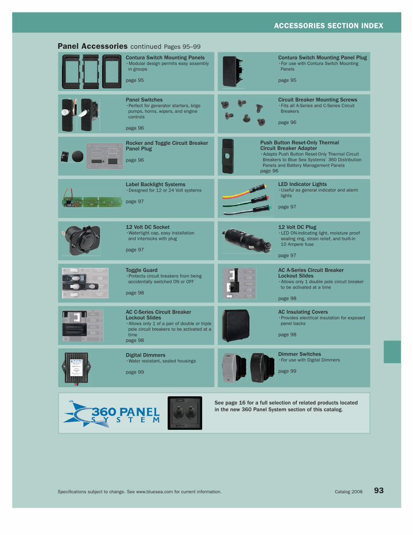
ACCESSORIES SECTION INDEX
Specifi cations subject to change. See www.bluesea.com for current information. Catalog 2008 93
Panel Accessories continued Pages 95–99
Contura Switch Mounting Panels•Modular design permits easy assembly
in groups
page 95
Panel Switches•Perfect for generator starters, bilge
pumps, horns, wipers, and engine
controls
page 96
Rocker and Toggle Circuit Breaker Panel Plug
page 96
Push Button Reset-Only ThermalCircuit Breaker Adapter •Adapts Push Button Reset-Only Thermal Circuit
Breakers to Blue Sea Systems’ 360 Distribution
Panels and Battery Management Panels
page 96
AC A-Series Circuit BreakerLockout Slides•Allows only 1 double pole circuit breaker
to be activated at a time
page 98
Toggle Guard•Protects circuit breakers from being
accidentally switched ON or OFF
page 98
Digital Dimmers•Water resistant, sealed housings
page 99
AC Insulating Covers•Provides electrical insulation for exposed
panel backs
page 98
Contura Switch Mounting Panel Plug•For use with Contura Switch Mounting
Panels
page 95
Label Backlight Systems•Designed for 12 or 24 Volt systems
page 97
12 Volt DC Socket•Watertight cap, easy installation
and interlocks with plug
page 97
12 Volt DC Plug•LED ON-indicating light, moisture proof
sealing ring, strain relief, and built-in
10 Ampere fuse
page 97
Circuit Breaker Mounting Screws•Fits all A-Series and C-Series Circuit
Breakers
page 96
LED Indicator Lights•Useful as general indicator and alarm
lights
page 97
Dimmer Switches•For use with Digital Dimmers
page 99
AC C-Series Circuit BreakerLockout Slides•Allows only 1 of a pair of double or triple
pole circuit breakers to be activated at a
time
page 98
+
OFF ON
+
See page 16 for a full selection of related products locatedin the new 360 Panel System section of this catalog.

ACCESSORIES
Specifi cations subject to change. See www.bluesea.com for current information. Blue Sea Systems
4150
( ) = Momentary
WeatherDeck™ Toggle Switches Single Pole
• Specially manufactured for use in WeatherDeck™ Waterproof Panels (pages 56–58)
• Rated IP67—temporary immersion for 30 minutes, when mounted with a
WeatherDeck™ Toggle Switch Boot (see below)
• Nickel-plated brass and phenolic non-corrosive construction
Specifications
Rating: 250 Volts AC 10 Amperes
Rating: 125 Volts AC 15 Amperes
Rating: 12 Volts DC 15 Amperes
Terminal Size 0.25" (6.35mm)
Terminal Type Quick Connect Tab
PN Description Weight Lb (Kg)
4138 Black Toggle Switch Waterproof Boot 0.04 (0.02)
WeatherDeck™ Toggle Switch Boots• Replaces dress nut for mounting on WeatherDeck™ Waterproof Panel Switches
• Rated IP67—temporary immersion for 30 minutes
• UV resistant material resists discoloration and cracking
Specifications
Case Material UV Resistant Silicone Rubber
Thread Material Nickel Plated Brass
Thread 15/32"-32UNS-2A
Cutout
WeatherDeck™ Toggle Switch Double Pole
• For use in WeatherDeck™ Waterproof Panels (pages 56–58)
• Rated IP67—temporary immersion for 30 minutes, when mounted with a
WeatherDeck™ Toggle Switch Boot (see below)
• Nickel-plated brass and phenolic non-corrosive construction
Specifications
Rating: 30 Volts DC 5 Amperes
Terminal Size 0.25" (6.35mm)
Terminal Type Quick Connect Tab
Cutout
Water Resistant Fuse Holder• Easy to open
• Rated IP66 on front—withstands water from heavy seas
Specifications
Rating: 32 Volts DC 20 Amperes
Mounting Hole 0.50" (12.70mm)
5021
4155
4138
4155
94
PN Description Weight Lb (Kg)
5021 Water Resistant Fuse Holder 0.02 (0.01)
PN Pole/Throw Action
4155 DPDT ON–OFF–ON
PN Pole/Throw Action
4150 SPST OFF–ON
4151 SPST OFF–(ON)
4152 SPDT ON–OFF–ON
4153 SPDT (ON)–OFF–ON
4154 SPDT (ON)–OFF–(ON)

ACCESSORIES
Specifi cations subject to change. See www.bluesea.com for current information. Catalog 2008
PN Gray PN Black Number of Lenses
8299 8296 None
8297 8294 Single
8298 8295 Double
8293 Actuator Removal Tool
Contura Switch Actuators• Mounts on any Blue Sea Systems’ Water Resistant Contura Switch
• Constructed of thermal plastic polycarbonate with a hard nylon surface overlay
• For each embedded LED, there is a corresponding number of lenses
82948297
SPST - Single Pole/Single Throw
SPDT - Single Pole/Double Throw
DPST - Double Pole/Single Throw
DPDT - Double Pole/Double Throw
Center terminal switch lever
Terminal
Off Position
SPST SPDT DPST DPDT
IGNITION PROTECTED
PN Gray PN Black Pole/Throw Action Embedded LEDs
8230 8282 SPST OFF–ON 1
8231 8292 SPST 0FF–(ON) 0
8232 8283 SPDT ON–OFF–ON 2
8233 8284 SPDT (ON)–OFF–ON 1
8234 8285 SPDT (0N)–OFF–(ON) 0
8218 8287 DPST OFF–ON 1
8219 8288 DPST OFF–(ON) 0
8220 8286 DPDT ON–OFF–ON 2
8221 8289 DPDT (ON)–OFF–ON 1
8222 8290 DPDT (ON)–OFF–(ON) 0
8275 - DPDT ON–ON 2
( ) = Momentary
Water Resistant Contura Switches• Vibration, shock, thermoshock, moisture and salt spray resistant
• Specially manufactured for use in Blue Sea Systems’ Contura Waterproof
Panels* (page 59)
• Ignition Protected - safe for installation aboard gasoline powered boats
• Meets UL 1500 and ISO 8846 ignition protection requirements
Specifications
Rating: 12 Volts DC 20 Amperes
Rating: 24 Volts DC 15 Amperes
Lighted LED rated 100,000 hours 1/2 life
Seals Internal and external gasket panel seal
Temperature Rating -40°C to 85°C
Mounting Hole 1.45" x 0.83" (36.83mm x 21.08mm)
LED Amperage 18 Milliamperes
PN Description
8278 Mounting Panel Plug
826882668267
PN Description Width in" (mm) Height in" (mm)
8267 End Mounting Panel 1.19 (30.23) 2.30 (58.42)
8266 Center Mounting Panel 1.03 (26.16) 2.30 (58.42)
8268 1 Position Mounting Panel 1.34 (34.04) 2.30 (58.42)
8259 3 Position Mounting Panel 3.40 (86.36) 2.30 (58.42)
8260 6 Position Mounting Panel 6.49 (164.85) 2.30 (58.42)
Contura Switch Mounting Panels• Modular design permits easy assembly in groups of varying sizes
• Mounting panels available in 1, 3, and 6 fixed position models
• Designed for mounting in 6 different panel thicknesses:
0.06" (1.57mm) 0.09" (2.36mm) 0.13" (3.17mm)
0.19" (4.75mm) 0.25" (6.35mm) 0.38" (9.52mm)
Cutout
Contura Switch Mounting Panel Plug• For use with Contura Switch Mounting Panels (see above)
8278PN 8278 Dimensions
95
* Use of standard Contura Switches will not maintain the integrity of the Contura Waterproof Panels.

ACCESSORIES
Specifi cations subject to change. See www.bluesea.com for current information. Blue Sea Systems
Panel Switches• Perfect for generator starters, bilge pumps, horns, wipers, engine controls
and any other application that requires switching action other than ON–OFF or
different pole configuration separate from circuit protection
• Panel switches mount in Blue Sea Systems’ A-Series Toggle Circuit Breaker Panels
• For use with A-Series Toggle Circuit Breaker Mounting Panel (page 86)
• Supplied with mounting adapter for standard 5/8" circuit breaker mounting hole
• Nickel-plated brass and phenolic non-corrosive construction
Specifications Toggle Switches Push Button Switch
Rating 250 Volts AC 10 Amperes 3 Amperes
Rating 125 Volts AC 15 Amperes 6 Amperes
Rating 32 Volts DC 15 Amperes 6 Amperes
Terminal Size 0.25" (6.35mm) 0.25" (6.35mm)
Terminal Type Quick Connect Tab Quick Connect Tab
Actuator Color White White
PN Type Pole/Throw Action Weight Lb (Kg)
8200 Push Button SPST OFF–(ON) 0.07 (0.03)
8204 Toggle SPST OFF–ON 0.08 (0.04)
8205 Toggle SPST OFF–(ON) 0.08 (0.04)
8206 Toggle SPDT ON–OFF–ON 0.08 (0.04)
8207 Toggle SPDT (ON)–OFF–ON 0.08 (0.04)
8208 Toggle SPDT (ON)–OFF–(ON) 0.08 (0.04)
8209 Toggle DPST* OFF–ON–(ON)
OFF–OFF–(ON)0.08 (0.04)
8210 Toggle DPST OFF–ON 0.08 (0.04)
8211 Toggle DPDT ON–OFF–ON 0.08 (0.04)
8212 Toggle DPDT (ON)–OFF–ON 0.08 (0.04)
8200 8204-8212
Cutout With AdapterCutout Without Adapter
Panel Switch Mounting Diagram* Progressive Two Circuit Switch - maintains circuit one while momentarily
switching circuit two
( ) = momentary
PN Description Weight Lb (Kg)
8037 Toggle Circuit Breaker Plug 0.03 (0.01)
Toggle Circuit Breaker Panel Plug• Black plug fits standard A-Series Toggle Circuit Breaker
apertures
8037
Circuit Breaker Mounting Screws• Fits all A-Series and C-Series Circuit Breakers
• Sold in packages of 6
PN Description Weight Lb (Kg)
8035 6-32 x 1/4" Flat Head 0.03 (0.01)
8035
PN Description Weight Lb (Kg)
4111 Circuit Breaker Panel Adapter 0.03 (0.01)
4111
Push Button Switch Toggle Switch
• Adapts Push Button Reset-Only Thermal Circuit Breaker
(page 46) to Blue Sea Systems’ 360 panels and battery
management panels
96
PN Description
4110 Rocker Circuit Breaker Plug
4110
+
OFF ON
+
Rocker Circuit Breaker Panel Plug• Black plug fits Rocker Circuit Breaker aperature
• Includes circuit breaker mounting screws, circuit breaker
panel plug, LED plug and blank label
Push Button Reset-Only ThermalCircuit Breaker Adapter

ACCESSORIES
Specifi cations subject to change. See www.bluesea.com for current information. Catalog 2008
Label Backlight System• Designed for 12 or 24 Volt systems
• Connects to 12 or 24 Volt sources via two
20 AWG wire leads
• Reverse polarity protection built-in
• 8065 snaps apart for 5 or 3 positions
Specifications
Maximum Voltage 24 Volts DC
Amperage Draw <7 mA per label
PN Description Weight Lb (Kg)
8065 8/5/3 Positions 0.08 (0.04)
8384 4 Positions 0.05 (0.02)
8069 10 Positions 0.09 (0.04)
8383 13 Positions 0.11 (0.05)
8065
LED Indicator Lights • Easily installed in Blue Sea Systems circuit breaker panels
• Simple push-in installation mounts in any thickness material
• Useful as general indicator and alarm lights
Specifications
Mounting Hole Size 11/64" (4.36mm)
Power Consumption 5 Milliwatts
E marked
PN Color Voltage Amperage Draw Weight Lb (Kg)
8033 Amber 12/24V DC 5 Milliamperes 0.03 (0.01)
8171 Red 12/24V DC 5 Milliamperes 0.03 (0.01)
8172 Green 12/24V DC 5 Milliamperes 0.03 (0.01)
8169 Amber 120V AC 0.5 Milliamperes 0.03 (0.01)
8066 Red 120V AC 0.5 Milliamperes 0.03 (0.01)
8034 Green 120V AC 0.5 Milliamperes 0.03 (0.01)
8167 Amber 230V AC 0.25 Milliamperes 0.03 (0.01)
8166 Red 230V AC 0.25 Milliamperes 0.03 (0.01)
8134 Green 230V AC 0.25 Milliamperes 0.03 (0.01)
97
12 Volt Socket-Plug System• Designed to withstand the rigors of wet environments and constant vibration
• Large contact surfaces for good electrical connection
• Twist lock system—plug locks securely into socket
• Corrosion-resistant materials to ensure solid contact and low voltage drop
• Internal strain relief and cord seal
• Nickel plated copper alloy used for all current carrying components
• Plug has a sealing ring around the shaft to keep out spray and
make it seat fi rmly in the outlet
• Plug features an LED ON-indicating light, moisture proof sealing
ring, strain relief and built-in 10A fuse
• Front panel, rear panel, or surface mount
• Socket features a watertight cap, easy installation and interlocks with plug
• 1012 and 1013 Heavy duty 18 gauge wire
• 1012 Cord reaches up to 6 feet
Specifications
Maximum Voltage 15 Volts DC
Maximum Socket Amperage 15 Amperes DC
Maximum Plug Amperage 10 Amperes DC
PN Description Weight Lb (Kg)
1010 12V DC Plug 0.08 (0.04)
1011 12V DC Socket 0.10 (0.05)
1012Single 12V DC Plug with Single 12V DC
Socket Extension0.54 (0.24)
1013Single 12V DC Plug with Dual 12V DC
Socket Extensions0.50 (0.23)
1014 Mounting Bracket for 12V DC Socket (1011) 0.07 (0.03)
101512 Volt DC Plug and 12V DC Socket Set
Includes 1010 and 10110.20 (0.09)
1012
NEW PRODUCT
1010 1011
1013 1014See page 16 for a full selection of related products located in the new 360 Panel System section of this catalog.

ACCESSORIES
Specifi cations subject to change. See www.bluesea.com for current information. Blue Sea Systems
4031 installed on 8086 AC/DC Circuit Breaker Panel
(pages 90–91)
AC A-Series Circuit Breaker Lockout Slide• Allows only 1 double pole AC circuit breaker to be activated at a time
• Guarantees that AC power from 2 or 3 sources (shore power, genset, or
inverter) will not be mixed
• Fits all double pole A-Series Toggle Circuit Breakers (page 70)
• Uses circuit breaker mounting screw holes–Requires no modification
• Includes mounting screws
Specifications
Material Acetal
Mounting Screw Size #6 Flat Head Screw
PN Poles AC Sources Weight Lb (Kg)
4125 2 2 0.04 (0.02)
4126 2 3 0.06 (0.03)
4125
AC C-Series Toggle Circuit Breaker Lockout Slide• Allows only 1 of a pair of double pole or triple pole
AC circuit breakers to be activated at a time
• Guarantees that AC power from 2 sources (shore power, genset,
or inverter) will not be mixed
• Fits all double or triple pole C-Series Toggle Circuit Breakers (page 72)
• Uses circuit breaker mounting screw holes
• Requires no special panel modification
• Includes mounting screws
Specifications
Material Acetal
Mounting Screw Size #6 Flat Head Screw
PN Poles Positions Weight Lb (Kg)
4130 2 2 0.06 (0.03)
4131 3 2 0.17 (0.08)
4131
4130
PN Description Weight Lb (Kg)
4026 Cover for 5-1/4" x 3-3/4" 0.12 (0.05)
4027 Cover for 5-1/4" x 7-1/2" 0.20 (0.09)
4028 Cover for 10-1/2" x 7-1/2" 0.50 (0.23)
4029 Cover for 1 Column x 8 Position + Meter 0.24 (0.11)
4031 Cover for 2 Column x 10 Position + Meter 0.38 (0.17)
AC Insulating Covers• Provides electrical insulation for exposed panel backs
• Provides mechanical protection for panel backs protruding into lockers
• Lightweight material is easily drilled for wire entrance and exit
• Meet ABYC safety requirements for panels with combined AC and DC loads
• PN 4029 and 4031–Used only for Blue Sea Systems’ toggle circuit
breaker panels
Specifications
Material ABS
4027
4031
Toggle Guard• Protects circuit breakers from being accidentally switched ON or OFF
• Fits all A-Series single pole toggle circuit breakers
• Fits all panel switches (page 96)
• Can be used on any brand of circuit breaker panel using standard toggle type circuit breakers
• Uses circuit breaker mounting screw hole
• Includes 2 mounting screws
Specifications
Material Acetal
Mounting Hole Size #6 Flat Head Screw
PN Description Weight Lb (Kg)
4100 Toggle Guard 0.05 (0.02)
4100 (2 shown)
4126
98

ACCESSORIES
Specifi cations subject to change. See www.bluesea.com for current information. Catalog 2008
Toggle Panel Switch• Mounts in Blue Sea Systems toggle panels
• For use with Digital Dimmer (see above)
Specifications
Voltage 250 Volts AC 10 Amperes
Voltage 125 Volts AC 15 Amperes
Voltage 32 Volts AC 15 Amperes
Terminal Size 0.25" (6.35mm)
Terminal Type Quick Connect Tab
Actuator Color White
PN Poles/Throw Action Weight Lb (Kg)
8208 Single/Double (ON)-OFF-(ON) 0.08 (0.04)
8208
8216 8291
PN Continuous Rating Width in" (mm) Height in" (mm) Depth in" (mm) Weight Lb (Kg)
7501 2A 1.67 (42.42) 2.05 (52.07) 1.50 (38.10) 0.28 (0.13)
7502 5A 2.16 (54.86) 3.06 (77.72) 1.60 (40.64) 0.40 (0.18)
7503 10A 2.16 (54.86) 3.06 (77.72) 1.60 (40.64) 0.58 (0.26)
7505 20A 2.16 (54.86) 3.06 (77.72) 1.60 (40.64) 0.56 (0.25)
Digital Dimmer• Continuous voltage control from 0 to 100% of input voltage
• Last setting memory–Power returns to previous setting with optional ON/OFF switch
• Supports multiple switch locations
• -20°C to +85°C operating temperature range
• Water resistant, sealed housings
• Operates on 10 to 32 Volt DC systems
• Requires SPDT momentary (ON)–OFF–(ON) switch such as PN 8216, 8291 or 8208 (see below)
7501
• Rated for dashboard gauge or small single fixture interior dimming
7502
• Rated for medium to large single fixture interior dimming
7503 and 7505
• Rated for multiple fixture area lighting dimming
• Robust aluminum housing
Specifications 7501 7502 7503 7505
Surge Rating: 10 sec 5 Amperes 10 Amperes 25 Amperes 50 Amperes
Internal Over Current Protection 10 Amperes 20 Amperes 50 Amperes 70 Amperes
Draw 0% output 5mA (0.005A) 5mA (0.005A) 5mA (0.005A) 5mA (0.005A)
7505
7502
7503
7501
PN Color Pole/Throw Action
8216 Gray Single/Double (ON)-OFF-(ON)
8291 Black Single/Double (ON)-OFF-(ON)
Water Resistant Contura Dimmer Switches• Mounts in Blue Sea Systems’ waterproof panels
• Legend–BRIGHT and DIM
• Contura Switch Mounting Panels (page 95)
• For use with Digital Dimmers (see above)
Specifications
Rating: 12 Volts DC 20 Amperes
Rating: 24 Volts DC 15 Amperes
Terminal Size 0.25” (6.35mm)
Terminal Type Quick Connect Tab
Seals Internal and External Gasket Panel Seal
Temperature Rating -40°C to 85°C
Mounting Hole 1.45" (36.83mm) x 0.83" (21.08mm)
IGNITION PROTECTED
99
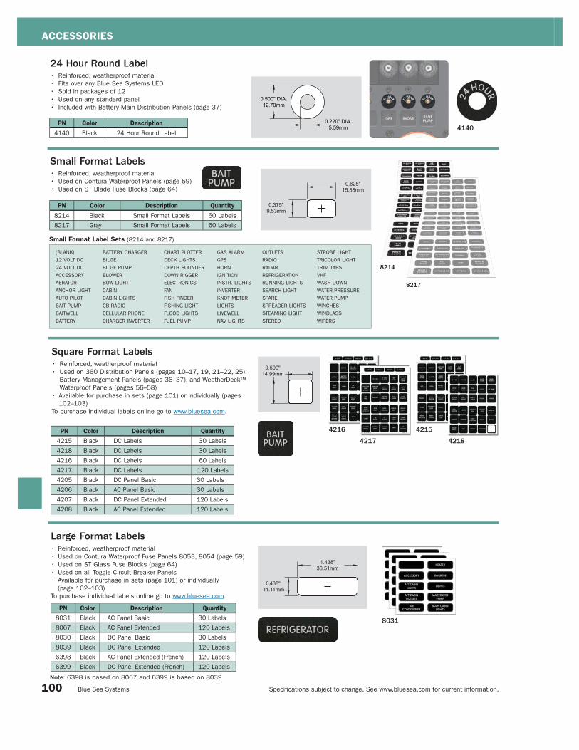
ACCESSORIES
Specifi cations subject to change. See www.bluesea.com for current information. Blue Sea Systems
8214
8217
PN Color Description Quantity
8214 Black Small Format Labels 60 Labels
8217 Gray Small Format Labels 60 Labels
PN Color Description Quantity
8031 Black AC Panel Basic 30 Labels
8067 Black AC Panel Extended 120 Labels
8030 Black DC Panel Basic 30 Labels
8039 Black DC Panel Extended 120 Labels
6398 Black AC Panel Extended (French) 120 Labels
6399 Black DC Panel Extended (French) 120 Labels
BATTERY CHARGER
BILGE
BILGE PUMP
BLOWER
BOW LIGHT
CABIN
CABIN LIGHTS
CB RADIO
CELLULAR PHONE
CHARGER INVERTER
GAS ALARM
GPS
HORN
IGNITION
INSTR. LIGHTS
INVERTER
KNOT METER
LIGHTS
LIVEWELL
NAV LIGHTS
CHART PLOTTER
DECK LIGHTS
DEPTH SOUNDER
DOWN RIGGER
ELECTRONICS
FAN
FISH FINDER
FISHING LIGHT
FLOOD LIGHTS
FUEL PUMP
Large Format Labels• Reinforced, weatherproof material
• Used on Contura Waterproof Fuse Panels 8053, 8054 (page 59)
• Used on ST Glass Fuse Blocks (page 64)
• Used on all Toggle Circuit Breaker Panels
• Available for purchase in sets (page 101) or individually
(page 102–103)
To purchase individual labels online go to www.bluesea.com.
24 Hour Round Label• Reinforced, weatherproof material
• Fits over any Blue Sea Systems LED
• Sold in packages of 12
• Used on any standard panel
• Included with Battery Main Distribution Panels (page 37)
PN Color Description
4140 Black 24 Hour Round Label4140
Square Format Labels• Reinforced, weatherproof material
• Used on 360 Distribution Panels (pages 10–17, 19, 21–22, 25),
Battery Management Panels (pages 36–37), and WeatherDeck™
Waterproof Panels (pages 56–58)
• Available for purchase in sets (page 101) or individually (pages
102–103)
To purchase individual labels online go to www.bluesea.com.
PN Color Description Quantity
4215 Black DC Labels 30 Labels
4218 Black DC Labels 30 Labels
4216 Black DC Labels 60 Labels
4217 Black DC Labels 120 Labels
4205 Black DC Panel Basic 30 Labels
4206 Black AC Panel Basic 30 Labels
4207 Black DC Panel Extended 120 Labels
4208 Black AC Panel Extended 120 Labels
4215
4218
4216
4217
Small Format Labels• Reinforced, weatherproof material
• Used on Contura Waterproof Panels (page 59)
• Used on ST Blade Fuse Blocks (page 64)
Note: 6398 is based on 8067 and 6399 is based on 8039
100
(BLANK)
12 VOLT DC
24 VOLT DC
ACCESSORY
AERATOR
ANCHOR LIGHT
AUTO PILOT
BAIT PUMP
BAITWELL
BATTERY
OUTLETS
RADIO
RADAR
REFRIGERATION
RUNNING LIGHTS
SEARCH LIGHT
SPARE
SPREADER LIGHTS
STEAMING LIGHT
STEREO
STROBE LIGHT
TRICOLOR LIGHT
TRIM TABS
VHF
WASH DOWN
WATER PRESSURE
WATER PUMP
WINCHES
WINDLASS
WIPERS
Small Format Label Sets (8214 and 8217)
8031

ACCESSORIES
Specifi cations subject to change. See www.bluesea.com for current information. Catalog 2008 101
ACCESSORY
AERATOR
ANCHOR LIGHT
AUTOPILOT
BAIT PUMP
BILGE PUMP
BLOWER
CABIN LIGHTS
DEPTH SOUNDER
ELECTRONICS
GPS
HORN
INSTRUMENTS
KNOTMETER
NAV LIGHTS
(BLANK)
12 VOLT DC
12 VOLT DC OUTLETS
ANCHOR WASH DOWN
BAITWELL
BATTERY
BATTERY PARALLEL
BILGE
BILGE PUMP 2
BILGE PUMP ON-OFF-AUTO
(BLANK)
12 VOLT DC
12 VOLT DC OUTLETS
24 VOLT DC
AIR HORN
ANCHOR LIGHT MAIN
ANCHOR LIGHT MIZZEN
ANCHOR WASH DOWN
APPLIANCES
ARCH LIGHTS
AUTO/MAN
BAITWELL
BATTERY
BATTERY PARALLEL
BILGE ALARM
BILGE PUMP 2
BILGE PUMP ON-OFF-AUTO
BOW LIGHT
ACCESSORY
ANCHOR LIGHT
AUTOPILOT
BILGE PUMP
BLOWER
COMPASS LIGHT
DEPTH SOUNDER
ELECTRONICS
ENGINE INSTRUMENTS
FAN
FOREDECK LIGHT
FWD CABIN LIGHTS
GPS
HORN
KNOTMETER
(BLANK)
ACCESSORY
AFT CABIN LIGHTS
AFT CABIN OUTLETS
AIR CONDITIONER
AIR CONDITIONER 2
APPLIANCES
BATTERY CHARGER
CABIN OUTLETS
COMPUTER
ENTERTAINMENT CENTER
FWD CABIN LIGHTS
FWD CABIN OUTLETS
GALLEY
GALLEY OUTLETS
(BLANK)
120 VOLT AC OUTLETS
120 VOLTS AC / 60 HZ
AC COMPRESSOR
AC FAN
AC MAIN
AC PANEL
AC POWER
AC REFRIGERATOR
AC SUB PANEL
AFT CABIN
AFT HEAD
AIR CONDITIONER 3
AIR CONDITIONER 4
ALARM SYSTEM
AMPLIFIER
AUDIO/VIDEO SYSTEM
BATTERY CHARGER 2
(BLANK)
12 VOLT DC
12 VOLT DC OUTLETS
AFT CABIN
AFT HEAD
ALARM SYSTEM
ANCHOR WASH DOWN
BAIT PUMP
BILGE ALARM
BILGE PUMP 2
BRIDGE INSTRUMENTS
CABIN 2 LIGHTS
CABIN 3 LIGHTS
CABIN 4 LIGHTS
CABIN FANS
CABIN LIGHTS
CB RADIO
CELLULAR PHONE
CHART LIGHT
CHART PLOTTER
COCKPIT LIGHTS
COLOR SOUNDER
COMM ELECTRONICS
DC LIGHTS
DC MAIN
DC OUTLETS
DC REFRIGERATOR
DC SUB PANEL
DECK LIGHTS
DECK LIGHTS AFT
DECK LIGHTS FWD
DEPTH RECORDER
DEPTH/SPEED
DESALINATOR
DIMMER
DINING AREA LIGHTS
Square and Large Format Panel Label SetsDC Label Set (4215)
RADAR
REFRIGERATOR
RUNNING LIGHTS
SEARCH LIGHT
SPARE
SPREADER LIGHTS
STEAMING LIGHT
STEREO
TRIM TABS
VHF
WASH DOWN
WATER PRESSURE
WATER PUMP
WINDLASS
WIPERS
DC Label Set (4216)
BOW LIGHT
CABIN
CB RADIO
CELLULAR PHONE
CHART LIGHT
CHART PLOTTER
COCKPIT LIGHTS
COMPASS LIGHT
COURTESY LIGHTS
DAVIT
DC OUTLETS
DC SUB PANEL
DECK LIGHTS
DOCKING LIGHTS
DOWN RIGGER
ELECTRIC HATCH
ENGINE ROOM BLOWER
ENGINE ROOM LIGHTS
FAN
FISH FINDER
FISHING LIGHT
FISHWELL PUMP
FLOOD LIGHTS
FRESH WATER PUMP
FUEL PUMP
GALLEY OUTLETS
GAS ALARM
GPS/PLOTTER
HEAD
IGNITION
INSTRUMENT LIGHTS
LIGHTS
LIVEWELL
MACERATOR PUMP
NAV LIGHT ANCHOR-OFF-NAV
OUTLETS
PUMPOUT
RADIO
SEAWATER WASH DOWN
SHOWER SUMP PUMP
SSB
STERN LIGHT
STROBE LIGHT
TRICOLOR LIGHT
TROLLING MOTOR
WASHDOWN
WATER MAKER
WINCHES
WIPER PORT
WIPER STBD
DC Label Set (4218)
12 VOLT DC
24 VOLT DC
ALARM
BILGE PUMP
BILGE PUMP 2
BILGE PUMP 3
BILGE PUMP 4
BOW THRUSTER
CLOCK
DC MAIN
DC SUB PANEL
ELECTRONICS
ENGINE
ENGINES
ENG 1/ENG 2
GENERATOR
HOUSE
HOUSE/ENG
HOUSE/GEN
INVERTER
LIGHTS
MEMORY
PORT/STBD ENG
RADAR
RADIO
SOLAR PANEL
VHF
WINCH
WINDLASS
Blank (Write On)
DC Panel Basic (4205 and 8030)
LIGHTS
MACERATOR PUMP
MAIN CABIN LIGHTS
RADAR
REFRIGERATOR
RUNNING LIGHTS
SAILING INSTRUMENTS
SPARE
SPREADER LIGHTS
STEAMING LIGHT
STEREO
STROBE LIGHT
TRICOLOR LIGHT
VHF
WATER PRESSURE
AC Panel Basic (4206 and 8031)
HEATER
INVERTER
LIGHTS
MACERATOR PUMP
MAIN CABIN LIGHTS
MAIN CABIN OUTLETS
MICROWAVE
OUTLETS
REFRIGERATOR
SPARE
STOVE
TV/STEREO
VCR
WASHER/DRYER
WATER HEATER
DC Label Set (4217)
BOW THRUSTER
BRIDGE INSTRUMENTS
BRIDGE LIGHTS
CABIN
CB RADIO
CD PLAYER
CHART LIGHT
CHART PLOTTER
COCKPIT LIGHTS
COMPASS LIGHT
COURTESY LIGHTS
DAVIT
DC OUTLETS
DC SUB PANEL
DECK LIGHTS
DEFROSTER
DEPTH/SPEED
DIMMER
DISCHARGE PUMP
DOCKING LIGHT PORT
DOCKING LIGHT STBD
DOCKING LIGHTS
DOWN RIGGER
ELECTRIC HATCH
ENGINE HATCH
ENGINE INSTRUMENTS
ENGINE ROOM BLOWER
ENGINE ROOM LIGHTS
ENGINE SHUTDOWN
ENTRY STEP
FAN
FAN 2
FIRE ALARM
FIRE EXT
FISH FINDER
FISHING LIGHT
FISHWELL PUMP
FLOOD LIGHTS
FLYBRIDGE
FLYBRIDGE ELECTRONICS
FLYBRIDGE LIGHTS
FOG LIGHTS
FOREDECK LIGHT
FRESH WATER PUMP
FRESH WATER WASH DOWN
FUEL PUMP
FUEL TRANSFER
FURLER JIB
FURLER MAINSAIL
GALLEY
GAS ALARM
GPS/PLOTTER
HAILER
HAM RADIO
HEAD
HEATER
IGNITION
INSTRUMENT LIGHTS
INTERCOM HAILER
LAZARETTE LIGHTS
LIGHTER
LIGHTS
LIVEWELL
LOCKER LIGHTS
LPG CONTROL
MAIN
MAST LIGHTS
MASTHEAD LIGHT
MIZZEN FLOOD
NAVIGATION ELECTRONICS
NAVIGATION INSTRUMENTS
NAV LIGHT ANCHOR OFF NAV
ON-OFF
OUTLETS
PUMP
PUMPOUT
RADIO
ROD LOCKER
RUDDER ANGLE INDICATOR
SAILING CONTROLS
SAILING INSTRUMENTS
SALT WATER PUMP
SEAWATER WASH DOWN
SHOWER SUMP PUMP
SOLAR PANEL
SSB
START-STOP
STERN LIGHT
STROBE LIGHT
SUMP PUMP
TRANSFER
TRICOLOR LIGHT
TROLLING MOTOR
WASHDOWN PUMP
WASHDOWN
WINCHES
WIND GENERATOR
WIND INSTRUMENTS
WINDSHIELD WASHER
WIPER CENTER
WIPER PORT
WIPER STBD
DOCKING LIGHTS
EMERGENCY LIGHTS
ENGINE ROOM BILGE ALARM
ENGINE ROOM LIGHTS
ENGINE ROOM PANEL MAIN
ENGINE ALARM
EXTERIOR LIGHTS
FAN 2
FIRE ALARM
FISHING LIGHT
FLOOD LIGHTS
FLYBRIDGE ELECTRONICS
FLYBRIDGE LIGHTS
FRESH WATER PUMP
FRESH WATER WASH DOWN
GALLEY LIGHTS
GPS/PLOTTER
HAILER
HAM RADIO
HEAD
HEAD LIGHTS
HEAD LIGHTS 2
HEATER 2
HELM ELECTRONICS
HELM GAUGES
HELM INSTRUMENTS
HIGH WATER ALARM
HOLDING TANK
HOLDING TANK ALARM
HOLDING TANK PUMP
INSTRUMENT LIGHTS
INSTRUMENTS
INTERCOM
INTERIOR LIGHTS
LIGHTS 2
LIVEWELL
LOG
LORAN
MAIN CABIN
MAP LIGHT
MAST LIGHTS
NAV STATION ELECTRONICS
NAV STATION GAUGES
NAV STATION INSTRUMENTS
NAV STATION LIGHTS
NAVIGATION ELECTRONICS
NAVIGATION INSTRUMENTS
NAVIGATION LIGHTS
RACK LIGHTS
RADIO
SALOON
SALOON LIGHTS
SAT/COM
SAT/NAV
SATELLITE DISH
SEARCHLIGHT
SEAWATER TEMP
SEAWATER WASH DOWN
SECURITY SYSTEM
SHOWER SUMP PUMP
SONAR
SPEED/LOG
SSB
SUB PANEL
SUMP PUMP
TELEPHONE SYSTEM
TRACK LIGHTS
TRANSFER PUMP
TRIM TABS
TV
TV/VCR
UTILITY
VIDEO PLOTTER
WATER ALARM
WATER MAKER
WATER PUMP
WEATHER FAX
WEATHER INSTRUMENT
WINCHES
WIND INSTRUMENTS
WINDEX LIGHT
WIPER PORT
WIPER STBD
WIPERS
BRIDGE LIGHTS
BRIDGE OUTLETS
CABIN
CABIN 2
CABIN 2 LIGHTS
CABIN 2 OUTLETS
CABIN 3
CABIN 3 LIGHTS
CABIN 3 OUTLETS
CABIN 4
CABIN 4 LIGHTS
CABIN 4 OUTLETS
CABIN HEATER
CABIN LIGHTS
CCTV
CHARGER/INVERTER
COCKPIT LIGHTS
COCKPIT REFRIGERATOR
COMPARTMENT LIGHT
COOKTOP
DECK LIGHTS
DIMMER
DINING AREA LIGHTS
DINING AREA OUTLETS
DISHWASHER
DISPOSAL
DRYER
EMERGENCY LIGHTS
ENGINE ROOM LIGHTS
ENGINE ROOM OUTLETS
EXHAUST FAN
EXTERIOR LIGHTS
FAN
FAN 2
FAN 3
FAN 4
FLOOD LIGHTS
FREEZER
FURNACE
GALLEY APPLIANCES
GALLEY LIGHTS
GARBAGE DISPOSAL
GENERATOR 1
GFI OUTLET
HALLWAY LIGHTS
HEAD 2 OUTLETS
HEAD 3 OUTLETS
HEAD 4 OUTLETS
HEAD LIGHTS
HEAD LIGHTS 2
HEAD LIGHTS 3
HEAD LIGHTS 4
HEAD OUTLETS
HEADLIGHTS
HEATER 2
HEATER 3
HEATER 4
HOOD FAN
ICEMAKER
INTERIOR LIGHTS
INVERTER OUTLET
ISOLATION TRANSFORMER
LAZARETTE LIGHTS
LECTRASAN
LIGHTS 2
LIGHTS 3
LIGHTS 4
LIGHTS AFT
LIGHTS FWD
MAIN
MAIN BREAKER
MAIN CABIN
NAV STATION LIGHTS
OUTLETS 2
OUTLETS 3
OUTLETS 4
OUTLETS DECK
OUTLETS EXTERIOR
OUTLETS INTERIOR
RACK OUTLETS
RANGE
REFRIGERATOR/FREEZER
REVERSE POLARITY
SALOON
SALOON HEATER
SALOON LIGHTS
SALOON OUTLETS
SATELLITE DISH
SHIP
SHORE
SHORE POWER
STEREO
STOVE/MICROWAVE
SUB PANEL
TELEPHONE SYSTEM
TRACK LIGHTS
TRASH COMPACTOR
TV
UPS SYSTEM
VACUUM
VIDEO SYSTEM
WASHER
WATER MAKER
AC Panel Extended Label Sets (4208 and 8067)
DC Panel Extended Label Sets (4207 and 8039)

ACCESSORIES
Specifi cations subject to change. See www.bluesea.com for current information. Blue Sea Systems 102
1 #1
2 #2
3 (BLANK)
5 12 VOLT DC
4 12 VOLT DC OUTLETS
499 12 VOLT OUTLETS INSIDE
500 12 VOLT OUTLETS OUTSIDE
7 120 VOLT AC / 60 HZ
6 120 VOLT AC OUTLETS
502 120 VOLT/60HZ SHORE POWER
517 120/240V 60HZ SHORE POWER
516 120/240V AC / 60HZ
526 230 VOLT AC / 50 HZ
10 24 VOLT DC
9 24 VOLT DC OUTLETS
8 240 VOLTS AC
460 240 VOLTS AC / 60 HZ
515 250 VOLT/50HZ SHORE POWER
468 250 VOLTS AC 50 HZ
462 AC BUS 1
11 AC COMPRESSOR
12 AC FAN
13 AC MAIN
14 AC PANEL
15 AC POWER
16 AC REFRIGERATOR
17 AC SUB PANEL
18 ACCESSORY
19 ADF
20 AERATOR
21 AFT CABIN
22 AFT CABIN LIGHTS
23 AFT CABIN OUTLETS
530 AFT DISCHARGE PUMP
24 AFT HEAD
25 AIR COMPRESSOR
26 AIR CONDITIONER
27 AIR CONDITIONER 2
28 AIR CONDITIONER 3
29 AIR CONDITIONER 4
30 AIR CONDITIONER PUMP
31 AIR HORN
32 ALARM SYSTEM
461 ALTERNATOR
33 ALTERNATOR DISCONNECT
34 AMPLIFIER
35 ANCHOR LIGHT
36 ANCHOR LIGHT MAIN
37 ANCHOR LIGHT MIZZEN
38 ANCHOR WASH DOWN
39 APPLIANCES
40 ARCH LIGHTS
41 AUDIO/VIDEO SYSTEM
525 AUTO FILL
42 AUTO/MAN
524 AUTOMATIC CHARGING RELAY
43 AUTOPILOT
44 BAIT PUMP
45 BAITWELL
46 BALLAST CONTROLS
47 BALLAST PUMP
48 BAR
481 BATHROOM
49 BATTERY
473 BATTERY 1
474 BATTERY 2
50 BATTERY CHARGER
51 BATTERY CHARGER 2
52 BATTERY COMPARTMENT
53 BATTERY PARALLEL
54 BEACON
480 BEDROOM
485 BEDROOM SLIDEOUT
55 BILGE
56 BILGE ALARM
57 BILGE ALARM 2
58 BILGE ALARM 3
59 BILGE ALARM 4
60 BILGE LIGHTS
61 BILGE PUMP
62 BILGE PUMP 2
63 BILGE PUMP 3
64 BILGE PUMP 4
453 BILGE PUMP ON-OFF-AUTO
65 BLOWER
66 BOAT DAVIT
67 BOOM LIGHT
68 BOW LIGHT
69 BOW THRUSTER
70 BRIDGE
71 BRIDGE INSTRUMENTS
72 BRIDGE LIGHTS
73 BRIDGE OUTLETS
74 CABIN
75 CABIN 2
501 CABIN 2 FAN
76 CABIN 2 LIGHTS
77 CABIN 2 OUTLETS
78 CABIN 3
79 CABIN 3 LIGHTS
80 CABIN 3 OUTLETS
81 CABIN 4
82 CABIN 4 LIGHTS
83 CABIN 4 OUTLETS
84 CABIN FAN
85 CABIN HEATER
86 CABIN LIGHTS
87 CABIN OUTLETS
88 CABLEMASTER
89 CASSETTE PLAYER
90 CB RADIO
91 CCTV
92 CD PLAYER
93 CELLULAR PHONE
94 CHARGER/INVERTER
95 CHART LIGHT
96 CHART PLOTTER
97 CHOKE
98 CIRCULATOR PUMP
508 CLOCK
99 CLOSET LIGHT
100 COCKPIT LIGHTS
101 COCKPIT REFRIGERATOR
102 COLOR SOUNDER
103 COMM ELECTRONICS
104 COMPARTMENT HEATER
105 COMPARTMENT LIGHT
106 COMPASS LIGHT
107 COMPUTER
514 COMPUTER DISPLAY
108 CONDENSER PUMP
109 CONSOLE LIGHT
110 CONVERTER
111 COOKING GRILL
112 COOKTOP
113 COOLING PUMP
114 COURTESY LIGHTS
115 CREW LIGHTS
116 CREW QUARTERS
117 DAVIT
118 DC LIGHTS
119 DC MAIN
120 DC OUTLETS
121 DC REFRIGERATOR
122 DC SUB PANEL
123 DECK
124 DECK LIGHTS
125 DECK LIGHTS AFT
126 DECK LIGHTS FWD
127 DECK LIGHTS PORT
128 DECK LIGHTS STBD
129 DEFROSTER
130 DEPTH RECORDER
131 DEPTH SOUNDER
132 DEPTH/SPEED
133 DESALINATOR
134 DIMMER
135 DINING AREA LIGHTS
136 DINING AREA OUTLETS
137 DISCHARGE PUMP
138 DISHWASHER
139 DISPOSAL
140 DIVE COMPRESSOR
141 DOCKING LIGHT PORT
142 DOCKING LIGHT STBD
143 DOCKING LIGHTS
144 DOWN RIGGER
145 DRYER
146 DUMP VALVES
147 ELECTRIC HATCH
469 ELECTRONIC CONTROL UNIT
148 ELECTRONICS
149 EMERGENCY BACKUP SYS
150 EMERGENCY LIGHTS
151 EMERGENCY PUMPS
158 ENGINE ALARM
159 ENGINE BLOCK HEATER
160 ENGINE CONTROL PORT
161 ENGINE CONTROL STBD
162 ENGINE CONTROLS
Label Number Label Text
163 ENGINE DRIVEN REFRIG
164 ENGINE EXHAUST FAN
165 ENGINE HATCH
166 ENGINE HEATER PORT
167 ENGINE HEATER STBD
168 ENGINE INSTRUMENTS
169 ENGINE OIL PAN PUMP
152 ENGINE ROOM BILGE ALARM
153 ENGINE ROOM BLOWER
154 ENGINE ROOM HEATER
155 ENGINE ROOM LIGHTS
156 ENGINE ROOM OUTLETS
157 ENGINE ROOM PANEL MAIN
170 ENGINE SHUTDOWN
171 ENGINE TEMP
172 ENTERTAINMENT CENTER
173 ENTRANCE DOOR
174 ENTRY STEP
175 EXHAUST FAN
176 EXHAUST TEMP
177 EXTERIOR
178 EXTERIOR LIGHTS
179 FAN
180 FAN 2
181 FAN 3
182 FAN 4
183 FAX
184 FILLING PUMP
185 FIRE ALARM
186 FIRE EXT
187 FIRE HORN
459 FISH FINDER
188 FISHBOX ICEMAKER
520 FISHBOX PUMP
521 FISHBOX REFRIGERATOR
189 FISHING LIGHT
487 FISHWELL PUMP
488 FISHWELL PUMP 2
190 FLOOD LIGHTS
191 FLOSCAN
192 FLYBRIDGE
193 FLYBRIDGE ELECTRONICS
194 FLYBRIDGE LIGHTS
195 FLYBRIDGE OUTLETS
196 FOG LIGHTS
197 FOREDECK LIGHT
198 FREEZER
199 FRESH WATER
200 FRESH WATER PUMP
201 FRESH WATER PUMP 2
202 FRESH WATER PUMP 3
203 FRESH WATER PUMP 4
204 FRESH WATER WASH DOWN
482 FRONT SLIDEOUT
205 FUEL PRIMER PUMP
206 FUEL PUMP
207 FUEL PUMP 2
208 FUEL PUMP 3
209 FUEL PUMP 4
210 FUEL TANK HEATER
211 FUEL TRANSFER
507 FUME DETECTOR
212 FURLER JIB
213 FURLER MAINSAIL
214 FURLER SPINNAKER
215 FURNACE
216 FWD CABIN
217 FWD CABIN LIGHTS
218 FWD CABIN OUTLETS
529 FWD DISCHARGE PUMP
528 FWD HEAD
219 GALLEY
220 GALLEY APPLIANCES
221 GALLEY DRAIN
222 GALLEY FAN
223 GALLEY LIGHTS
224 GALLEY OUTLETS
490 GALVANIC ISOLATOR
225 GARBAGE DISPOSAL
226 GAS ALARM
227 GENERAL PURPOSE
523 GENERATOR
228 GENERATOR 1
229 GENERATOR 2
454 GENERATOR OFF-ON-START
230 GENERATOR ROOM BLOWER
466 GENERATOR RUNNING
455 GENERATOR STOP
231 GFI OUTLET
232 GPS
Label Number Label Text Label Number Label Text
Individual Square and Large Format Panel LabelsTo order individual labels please indicate the PN (6520 or 8063) and the Label Number
Square FormatPN 6520
Large FormatPN 8063

ACCESSORIES
Specifi cations subject to change. See www.bluesea.com for current information. Catalog 2008 103
233 GPS/LORAN
234 GPS/PLOTTER
510 GUN LOCKS
235 GYRO COMPASS
236 HAILER
237 HALLWAY LIGHTS
238 HALON FIRE SYSTEM
239 HAM RADIO
240 HEAD
241 HEAD 2
242 HEAD 2 FAN
243 HEAD 2 OUTLETS
244 HEAD 3
245 HEAD 3 FAN
246 HEAD 3 OUTLETS
247 HEAD 4
248 HEAD 4 FAN
249 HEAD 4 OUTLETS
250 HEAD FAN
251 HEAD LIGHTS
252 HEAD LIGHTS 2
253 HEAD LIGHTS 3
254 HEAD LIGHTS 4
255 HEAD OUTLETS
256 HEADLIGHTS
257 HEATER
519 HEATER & AIR CONDITIONER
258 HEATER 2
259 HEATER 3
260 HEATER 4
261 HELM ELECTRONICS
262 HELM GAUGES
263 HELM INSTRUMENTS
264 HIGH WATER ALARM
265 HOLDING TANK
266 HOLDING TANK ALARM
267 HOLDING TANK PUMP
268 HOOD FAN
269 HOOD LIGHT
270 HORN
475 HOT TUB
271 HOT WATER PUMP
272 HYDRAULIC ALARM
273 HYDRAULIC SYSTEM
274 HYDRAULIC TANK ALARM
275 ICEMAKER
276 IGNITION
277 IGNITION PORT
278 IGNITION STBD
279 INSTRUMENT LIGHTS
280 INSTRUMENTS
281 INTERCOM
282 INTERCOM HAILER
283 INTERCOM/TELEPHONE
284 INTERIOR LIGHTS
285 INVERTER
467 INVERTER 2
476 INVERTER AC BUS
471 INVERTER AC SUPPLY
470 INVERTER DC SUPPLY
286 INVERTER OUTLET
287 ISOLATION TRANSFORMER
479 KITCHEN
484 KITCHEN SLIDEOUT
288 KNOTMETER
289 LAZARETTE LIGHTS
290 LECTRASAN
291 LIGHTER
292 LIGHTS
293 LIGHTS 2
294 LIGHTS 3
295 LIGHTS 4
296 LIGHTS AFT
494 LIGHTS AFT CABIN
297 LIGHTS FWD
493 LIGHTS MASTER CABIN
495 LIGHTS PANTRY
492 LIGHTS PILOTHOUSE
298 LIGHTS PORT
491 LIGHTS SETTEE
299 LIGHTS STBD
300 LIVEWELL
301 LIVEWELL INPUT
302 LIVEWELL OUTPUT
303 LOCKER LIGHTS
304 LOG
305 LORAN
306 LPG CONTROL
307 LUBE OIL PUMP
308 MACERATOR PUMP
309 MAIN
310 MAIN BREAKER
311 MAIN CABIN
312 MAIN CABIN LIGHTS
313 MAIN CABIN OUTLETS
314 MAIN SAIL FURLING
315 MAP LIGHT
316 MAST LIGHTS
317 MASTHEAD LIGHT
318 MICROWAVE
319 MINI DISC PLAYER
320 MIZZEN FLOOD
456 NAV LIGHT ANCHOR-OFF-NAV
321 NAV STATION ELECTRONICS
322 NAV STATION GUAGES
323 NAV STATION INSTRUMENTS
324 NAV STATION LIGHTS
325 NAVIGATION ELECTRONICS
326 NAVIGATION INSTRUMENTS
327 NAVIGATION LIGHTS
328 NIGHT LIGHTS
329 OFF
331 OIL CHANGE PUMP
332 ON
330 ON-OFF
333 OUTLETS
334 OUTLETS 2
335 OUTLETS 3
336 OUTLETS 4
505 OUTLETS AFT
337 OUTLETS DECK
506 OUTLETS ENGINE ROOM
338 OUTLETS EXTERIOR
503 OUTLETS FORWARD
339 OUTLETS INTERIOR
504 OUTLETS PILOT HOUSE
458 PANEL LIGHTS
496 PILOT HOUSE FAN
340 PORT
341 PORT THRUSTER
342 POWER
343 POWER WASHER
457 PRE-HEAT
344 PRIMARY WINCHES
345 PRINTER
346 PUMP
497 PUMP BLACK WATER
498 PUMP GRAY WATER
347 RACK LIGHTS
348 RACK OUTLETS
349 RADAR
350 RADAR ARCH LIGHTS
351 RADIO
352 RANGE
353 RDF
483 REAR SLIDEOUT
354 RECEIVER
355 RECEPTACLE
356 REFRIGERATOR
357 REFRIGERATOR PUMP
358 REFRIGERATOR/FREEZER
359 REGULATOR
360 REVERSE POLARITY
361 ROD LOCKER
489 RUDDER ANGLE INDICATOR
362 RUNNING LIGHTS
363 SAILING CONTROLS
364 SAILING INSTRUMENTS
365 SALOON
366 SALOON HEATER
367 SALOON LIGHTS
368 SALOON OUTLETS
369 SALT WATER PUMP
370 SAT/COM
371 SAT/NAV
372 SATELLITE DISH
373 SCRUBBER
374 SEARCHLIGHT
375 SEARCHLIGHT HAND HELD
376 SEARCHLIGHT REMOTE
377 SEAWATER TEMP
378 SEAWATER WASH DOWN
379 SECURITY SYSTEM
380 SHIP
381 SHORE
463 SHORE 1
464 SHORE 2
382 SHORE CORD REEL
383 SHORE POWER
384 SHORE POWER CORD
385 SHOWER SUMP PUMP
386 SINK DRAIN
486 SLIDEOUT
387 SOLAR PANEL
388 SONAR
389 SPARE
390 SPEED/LOG
391 SPREADER LIGHTS
392 SPREADER LT MIZZEN
393 SSB
394 STABILIZER
395 STARBOARD
396 START
398 START PORT
399 START STBD
397 START-STOP
400 STBD THRUSTER
401 STEAMING LIGHT
402 STEP LIGHT
403 STEREO
404 STERN LIGHT
509 STERN THRUSTER
405 STOP
406 STOVE
407 STOVE/MICROWAVE
408 STROBE LIGHT
409 SUB PANEL
410 SUMP PUMP
411 SUMP PUMP 2
412 SYNCHRO
413 TAPE DECK
414 TELEPHONE SYSTEM
415 TEST
416 TOWING LIGHTS
417 TRACK LIGHTS
465 TRANSFER
418 TRANSFER PUMP
419 TRANSFORMER
518 TRANSFORMER SECONDARY
420 TRASH COMPACTOR
478 TRAVEL LOCKS
421 TRICOLOR LIGHT
422 TRIM TABS
527 TROLLING MOTOR
423 TV
424 TV ANTENNA
425 TV/STEREO
426 TV/VCR
427 UPS SYSTEM
428 UTILITY
429 VACUUM
430 VACUUM PUMP
431 VCR
432 VHF
511 VHF 1
512 VHF 2
433 VIDEO PLOTTER
434 VIDEO SYSTEM
513 WASHDOWN PUMP
435 WASHER
436 WASHER/DRYER
437 WATER ALARM
438 WATER HEATER
439 WATER LEVEL
440 WATER MAKER
441 WATER PRESSURE
442 WATER PUMP
443 WEATHER FAX
444 WEATHER INSTRUMENT
445 WINCHES
477 WIND GENERATOR
446 WIND INSTRUMENTS
447 WINDEX LIGHT
448 WINDLASS
522 WINDSHIELD VENT
449 WINDSHIELD WASHER
472 WIPER CENTER
450 WIPER PORT
451 WIPER STBD
452 WIPERS
Label Number Label Text Label Number Label Text Label Number Label Text
Individual Square and Large Format Panel LabelsTo order individual labels please indicate the PN (6520 or 8063) and the Label Number
Square FormatPN 6520
Large FormatPN 8063

METERING AND ACCESSORIES INTRODUCTION
Specifi cations subject to change. See www.bluesea.com for current information. Blue Sea Systems
Meters and AccessoriesDefi nitionMeters are used to monitor a boat’s:
• DC electrical system—voltage and current
• AC electrical system—voltage, current, and frequency
PurposeMeters are necessary in a boat’s electrical system to manage the system: avoiding overload of shore cords, when to charge battery banks
and when chargers and alternators are not functioning properly, etc.
According to ABYC, “System voltmeters shall be installed in a main panel if the system is permanently connected to motor circuits,
generators, and inverters”. Frequency meters are useful for the management of generators.
Products in this SectionMeters: There are two styles of meter: Analog and digital. There are three sizes of analog meters: standard, compact, and DIN. There are
two digital meters: standard and clamp. Some digital meters have alarms to warn when there is a malfunction. Digital multimeters allow
for multiple functions in a single meter.
Meter Accessories: Panels are available to mount meters. There are DC shunts, shunt shifters that allow DC digital ammeters to read
positive side shunt applications such as alternator measurement, AC current transformers, and switches.
Digital Meters• Voltmeters, Ammeters, Frequency Meters, and Multimeters• Easy spin on mounting system• Readable in low light• Can be rear or front panel mounted
Splashproof front
3 levels of display brightness
Large, bright LED characters are easy to read in low light, at angles, and from a distance
AC high and low voltage and high amperage alarms, both audio and visual (8247 - page 107)
DC high and low voltage alarms, both audio and visual(8248 and 8251 - see page106)
Easy to surface mount inround 2" diameter hole
Digital Meter Rear Panel MountTo panel mount simply remove the bezel and mount in any Blue Sea Systems full
sized meter cutout
Digital Meter Front Panel MountSurface mounting features a fi nger nut and
locking ring for quick and easy installation
into a 2.00" (52.00mm) diameter hole.
• Direct replacement for standard size analog meters• Scan mode on multi-function units• Low current drain• Sleep mode on all units
Easy to panelmount withremovable bezel
104
1.50"

METERING AND ACCESSORIES SECTION INDEX
Specifi cations subject to change. See www.bluesea.com for current information. Catalog 2008 105
DC Digital Meters Page 106
AC Digital Meters Page 107
DC DIN Meters Page 108
AC DIN Meters Page 109
DC Analog Meters Page 110
AC Analog Meters Page 111
Meter Accessories Pages 112–113
Digital Multimeter with Alarm
Digital Multimeter with Alarm
AnalogAmmeters
AnalogVoltmeters
DIN Voltmeters DIN Ammeters
DIN Voltmeters DIN Ammeters
AnalogVoltmeters
Analog Voltmeter Panel
DC Shunts Meter Mounting Panels
Shunt Shifter
Digital Mini Clamp Multimeter
AnalogAmmeters
Digital Voltmeter
Digital Ammeter
Digital Voltmeter with Alarm
Digital Frequency Meter
Analog Zero CenterAmmeters
Digital Ammeter
Digital Voltmeter
AC Current Transformer
Digital Voltmeter Panel
DC Meter Panels and Clamp Meter Page 112
See page 9 for a full selection of related products locatedin the new 360 Panel System section of this catalog.

METERING AND ACCESSORIES
Specifi cations subject to change. See www.bluesea.com for current information. Blue Sea Systems
8235
8251
8248
8236
* ±1 least digit of resolution
Current MeasurementShunt: 500A–50mV
Range: ±500A DC
Resolution (0.0–99.9): 0.1A DC
Resolution (100–500): 1.0A DC
Accuracy (% of Reading): ±0.5%*
Voltage MeasurementRange: 0–60V DC
Resolution: 0.01V DC
Accuracy (% of Reading): ±0.5%*
106
DC Digital MetersCommon Features• Splashproof front
• 3 levels of display brightness
8248 Multimeter with Alarm FeaturesHigh and low voltage, audio and visual alarms•
• Programmable sleep mode blanks display for power conservation
• Standard meter operates in negative side of circuit only. Shunt shifter 8242 (page 113) required
for positive side installation such as alternators
• Includes 500 Amp Shunt 8255 (page 113)
8251 Voltmeter with Alarm FeaturesHigh and low voltage, audio and visual alarms•
• Programmable sleep mode blanks display for power conservation
8235 Voltmeter Features• Manual sleep mode blanks display for power conservation
8236 Ammeter Features• Standard meter operates in negative side of circuit only. Shunt shifter 8242 (page 113) required
for positive side installation such as alternators
• Includes 500 Amp Shunt 8255 (page 113)
• Manual sleep mode blanks display for power conservation
Specifications
Input Voltage 7–60V DC1
Minimum Power Consumption 0.60 Watt2
Maximum Power Consumption 1.00 Watt2
Display Character Size 9/16" (14.29mm)
Dimensions Width 2.90" (73.66mm)
Height 2.43" (61.72mm)
Depth 3.40" (86.36mm)
1 Applicable for 12, 24, 32, 36, and 42 Volt DC systems2 Variable with voltage, display intensity, segments illuminated and sleep mode
PN Description Amperage Display Voltage DisplayCurrentMeasurement
VoltageMeasurement
Weight Lb (Kg)
8248Digital Multimeter
with Alarm–500 to +500A DC 0–60V DC
1.12
(0.51)
8251Digital Voltmeter
with AlarmN/A 0–60V DC -
0.45
(0.20)
8235 Digital Voltmeter N/A 0–60V DC -0.45
(0.20)
8236 Digital Ammeter –500 to +500A DC N/A -1.11
(0.50)
See page 9 for a full selection of related products located in the new 360 Panel System section of this catalog.

METERING AND ACCESSORIES
Specifi cations subject to change. See www.bluesea.com for current information. Catalog 2008 107
8239
8247
8238
8237
AC Digital MetersCommon Features• Splashproof front
• 3 levels of display brightness
8247 Multimeter with Alarm FeaturesHigh and low voltage and high amperage audio and visual alarms•
• Programmable sleep mode blanks display for power conservation
• Includes current transformer (page 113)
8239 Frequency Meter FeaturesManual sleep mode blanks display for power conservation•
8237 Voltmeter Features• Manual sleep mode blanks display for power conservation
8238 Ammeter Features• Manual sleep mode blanks display for power conservation
• Includes current transformer (page 113)
Specifications
Input Voltage 80–270V AC1
Minimum Power Consumption 0.010 Watt2
Maximum Power Consumption 0.027 Watt2
Display Character Size 9/16" (14.29mm)
Dimensions Width 2.90" (73.66mm)
Height 2.43" (61.72mm)
Depth 3.40" (86.36mm)
1 Applicable for 120 and 240 Volt AC single phase systems2 Variable with voltage, display intensity, segments illuminated and sleep mode
PN DescriptionAmperage Display
Voltage Display
Power Display
Frequency Display
Current3 Voltage4 Frequency5 Power6 Weight Lb (Kg)
8247Digital Multimeter
with Alarm
0–150
Amperes AC
80–270
Volts AC
0–45
Kilowatts
40–90
Hertz
0.78
(0.35)
8239Digital Frequency
MeterN/A N/A N/A
40–90
Hertz- - -
0.72
(0.35)
8237 Digital Voltmeter N/A80–270
Volts ACN/A N/A - - -
0.72
(0.35)
8238 Digital Ammeter0–150
Amperes ACN/A N/A N/A - - -
0.78
(0.35)
6 Power MeasurementRange 1 (Resolution 10W): 0.00–9990W
Range 2 (Resolution 0.1kW): 10–45kW
Accuracy (% of Reading): ±5.0% **
* For 120 & 240 Volt AC single phase systems** ±1 least digit of resolution
5 Frequency MeasurementRange: 40–90Hz
Resolution: 0.1Hz
Accuracy (% of Reading): ±1.0% **
(Calibrated with sine wave input)
3 Current MeasurementCurrent Transformer: 150A–50mV
Range 1 (Resolution 0.01A): 0.00–9.99A AC (RMS)
Range 2 (Resolution 0.10A): 10–150A AC (RMS)
Accuracy (% of Reading): ±1.0% **
4 Voltage MeasurementRange: 80–270V AC *
Resolution: 0.1V AC
Accuracy (% of Reading)
90-270V AC (RMS): ±1.0% **
80-90V AC (RMS): ±5.0% **

METERING AND ACCESSORIES
Specifi cations subject to change. See www.bluesea.com for current information. Blue Sea Systems 108
1053
1050
1055
1052
1051
1054
TERMINALCOVER
0.236"6.00mm
1.456"37.00mm
0.551"14.00mm
2.835"72.00mm
2.835"72.00mm
2.598"66.00mm
0.787"20.00mm
PN Description Shunt Type External Shunt Type Weight Lb (Kg)
1050 Voltmeter 8–16V DC - - 0.33 (0.15)
1051 Voltmeter 18–32V DC - - 0.33 (0.15)
1052 Ammeter 0–25A DC Internal - 0.33 (0.15)
1053 Ammeter 0–50A DC External 50 Millivolt at full scale 0.53 (0.24)
1054 Ammeter 0–100A DC External 50 Millivolt at full scale 0.53 (0.24)
1055 Ammeter 0–150A DC External 50 Millivolt at full scale 0.53 (0.24)
DC DIN MetersStandard European 72mm design. White matte dial with black printed scale and knife-edge pointer.
Common Features• Back-lit meter face
• Terminal cover included to prevent accidental short circuit
1050 and 1051 Voltmeter Features• 8–16 and 18–32 Volt ranges
• Simple 2-wire connection to DC positive and negative
• Meter senses and powers from same connections
1052 Ammeter Features• 0–25 Ampere range
• Simple 2-wire connection, no other power required
1053, 1054, and 1055 Ammeter Features• 0–50, 0–100, 0–150 Ampere ranges
• Simple 2-wire connection from shunt—no other power required
• Meter senses and powers from shunt connections
• Includes appropriate DC shunt (page 113)
Specifi cations
Meter Current = 1 mA at full scale
See page 23 for a full selection of related products located in the new 360 Panel System section of this catalog.

METERING AND ACCESSORIES
Specifi cations subject to change. See www.bluesea.com for current information. Catalog 2008 109
1058
1056
1057
PN Description Weight Lb (Kg)
1056 Voltmeter 0–150V AC 0.33 (0.15)
1057 Voltmeter 0–250V AC 0.33 (0.15)
1058 Ammeter 0–50A AC 0.43 (0.19)
AC DIN MetersStandard European 72mm design. White matte dial with black printed scale and knife-edge pointer.
Common Features• Back-lit meter face
• Terminal cover included to prevent accidental short circuit
1056 and 1057 Voltmeter Features• 0–150 and 0–250 Volt ranges
• Simple 2-wire connection to AC hot and neutral
• Meter senses and powers from same connections
1058 Ammeter Features• 0–50 Ampere range
• Simple 2-wire connection
• Meter senses and powers from coil slipped over wire to be measured
• 50 Milliamperes AC at full scale
TERMINALCOVER
0.236"6.00mm
1.456"37.00mm
0.551"14.00mm
2.835"72.00mm
2.835"72.00mm
2.598"66.00mm
0.787"20.00mm
See page 23 for a full selection of related products located in the new 360 Panel System section of this catalog.
Photo Courtesy of Hanse Yachts
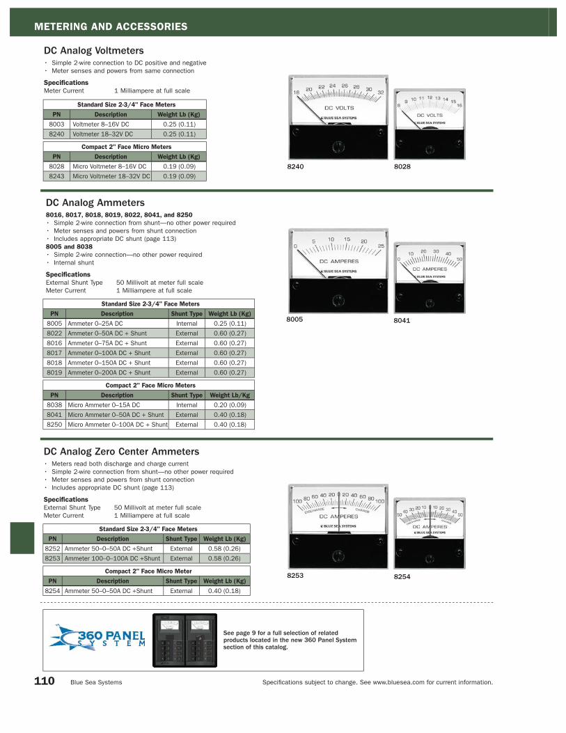
METERING AND ACCESSORIES
Specifi cations subject to change. See www.bluesea.com for current information. Blue Sea Systems
8028 8240
8005 8041
8253 8254
Standard Size 2-3/4" Face Meters
PN Description Shunt Type Weight Lb (Kg)
8252 Ammeter 50–0–50A DC +Shunt External 0.58 (0.26)
8253 Ammeter 100–0–100A DC +Shunt External 0.58 (0.26)
Compact 2" Face Micro Meter
PN Description Shunt Type Weight Lb (Kg)
8254 Ammeter 50–0–50A DC +Shunt External 0.40 (0.18)
DC Analog Voltmeters• Simple 2-wire connection to DC positive and negative
• Meter senses and powers from same connection
Specifications
Meter Current 1 Milliampere at full scale
Standard Size 2-3/4" Face Meters
PN Description Weight Lb (Kg)
8003 Voltmeter 8–16V DC 0.25 (0.11)
8240 Voltmeter 18–32V DC 0.25 (0.11)
Compact 2" Face Micro Meters
PN Description Weight Lb (Kg)
8028 Micro Voltmeter 8–16V DC 0.19 (0.09)
8243 Micro Voltmeter 18–32V DC 0.19 (0.09)
Standard Size 2-3/4" Face Meters
PN Description Shunt Type Weight Lb (Kg)
8005 Ammeter 0–25A DC Internal 0.25 (0.11)
8022 Ammeter 0–50A DC + Shunt External 0.60 (0.27)
8016 Ammeter 0–75A DC + Shunt External 0.60 (0.27)
8017 Ammeter 0–100A DC + Shunt External 0.60 (0.27)
8018 Ammeter 0–150A DC + Shunt External 0.60 (0.27)
8019 Ammeter 0–200A DC + Shunt External 0.60 (0.27)
Compact 2" Face Micro Meters
PN Description Shunt Type Weight Lb/Kg
8038 Micro Ammeter 0–15A DC Internal 0.20 (0.09)
8041 Micro Ammeter 0–50A DC + Shunt External 0.40 (0.18)
8250 Micro Ammeter 0–100A DC + Shunt External 0.40 (0.18)
DC Analog Ammeters8016, 8017, 8018, 8019, 8022, 8041, and 8250
• Simple 2-wire connection from shunt—no other power required
• Meter senses and powers from shunt connection
• Includes appropriate DC shunt (page 113)
8005 and 8038
• Simple 2-wire connection—no other power required
• Internal shunt
Specifications
External Shunt Type 50 Millivolt at meter full scale
Meter Current 1 Milliampere at full scale
DC Analog Zero Center Ammeters• Meters read both discharge and charge current
• Simple 2-wire connection from shunt—no other power required
• Meter senses and powers from shunt connection
• Includes appropriate DC shunt (page 113)
Specifications
External Shunt Type 50 Millivolt at meter full scale
Meter Current 1 Milliampere at full scale
110
See page 9 for a full selection of related products located in the new 360 Panel System section of this catalog.

METERING AND ACCESSORIES
Specifi cations subject to change. See www.bluesea.com for current information. Catalog 2008
9630 8246
9353 8245
AC Analog Voltmeters• Dial marked in 5 Volt increments
• Simple 2-wire connection to AC hot and neutral
• Meter senses and powers from same connection
Standard Size 2-3/4" Face Meters
PN Description Weight Lb (Kg)
9353 Voltmeter 0–150V AC 0.25 (0.11)
9354 Voltmeter 0–250V AC 0.26 (0.12)
Compact 2" Face Micro Meters
PN Description Weight Lb (Kg)
8244 Micro Voltmeter 0–150V AC 0.19 (0.09)
8245 Micro Voltmeter 0–250V AC 0.19 (0.09)
Standard Size 2-3/4" Face Meters
PN Description Weight Lb (Kg)
9630 Ammeter 0–50A AC + Transformer 0.30 (0.14)
8258 Ammeter 0–100A AC + Transformer 0.32 (0.15)
Compact 2" Face Micro Meter
PN Description Weight Lb (Kg)
8246 Micro Ammeter 0–50A AC + Transformer 0.26 (0.12)
AC Analog Ammeters• Simple 2-wire connection
• Meter senses and powers from coil slipped over wire to be measured
• Includes AC current transformer (page 113)
Specifications
Meter Current 50 Milliamperes AC at full scale
Standard Meter Dimensions Micro Meter Dimensions
111
Panel Mount Surface Mount
See page 9 for a full selection of related products located in the new 360 Panel System section of this catalog.

METERING AND ACCESSORIES
Specifi cations subject to change. See www.bluesea.com for current information. Blue Sea Systems
120/240V AC Digital Meter Panel• Perfect solution for monitoring 120/240 Volt AC systems
• Monitor Line 1 or Line 2 to Neutral and Line 1 to Line 2 voltages
• Intended for use with 8247 AC Digital Multimeter (Not included) (page 107)
• Includes two additional Current Transformers 8256 (page 113)
PN Description Width in" (mm) Height in" (mm)
8410 120/240V AC Digital Meter Panel 5.25 (133.35) 3.75 (95.25mm)8410
PN Description Weight Lb (Kg) Width in" (mm) Height in" (mm)
8013 Meter Mounting Panel For (1) 2-3/4" 0.25 (0.11) 5.25 (133.35) 3.75 (95.25mm)
8014 Meter Mounting Panel For (2) 2-3/4" 0.36 (0.16) 5.25 (133.35) 7.50 (190.50mm)
Meter Mounting Panels• Surface mounts standard 2-3/4" Analog or Digital Meters (pages 110–111)
Specifications
Panel Material 0.125" Aluminum 5052 Alloy
Panel Undercoating Mil-C-5541C or equivalent immersion
Panel Front Coating Two-part polyurethane slate gray finish8013
8014
PN Description Weight Lb (Kg) Width in" (mm) Height in" (mm)
8015 DC Analog Voltmeter Panel 0.49 (0.22) 5.25 (133.35) 3.75 (95.25mm)
DC Analog Voltmeter Panel• Includes standard 2-3/4" 8003 DC Analog Voltmeter (page 110)
• Displays voltage from 8–16 Volts DC
• 3 position switch for multiple battery banks
Specifications
Voltage 16 Volts DC Maximum
8015
PN Description Weight Lb (Kg) Width in" (mm) Height in" (mm)
8051 DC Digital Voltmeter Panel 0.64 (0.29) 5.25 (133.35) 3.75 (95.25mm)
DC Digital Voltmeter Panel• Includes 8235 DC Digital Voltmeter (page 106)
• 4 digit LED display—Display voltage from 0–60 Volts DC
• 3 position switch for multiple battery banks
Specifications
Voltage 60 Volts DC Maximum
8051
112
PN Description Weight Lb (Kg)
8110 Mini Clamp Multimeter 0.47 (0.21)
Mini Clamp Multimeter• Clamp allows measurement of AC and DC current in wires without
disturbing the circuits or contacting live terminals
• Compact size allows comfortable hand operation, portability,
and access to confined areas
• Auto range simplifies operation by automatically selecting the range
that best fits the data
• Additional functions include: Data Hold, Overload Display, and Auto Power-Off
• True RMS AC measurement is accurate for normal sine waves and the
modified sine wave outputs from inverters
Specifications
AC Amperes (Current) 0.01–400 Amperes DC
AC Voltage 0.001–600 Volts
DC Amperes (Current) 0.01–400 Amperes
DC Voltage 0.001–600 Volts
Resistance/Continuity Alarm 0.1–40M
Measurement Resolution 4300 counts
Certification and Agency Standards
E marked
CAT II, 600 Volts
(Includes test leads and carrying case)NEW PRODUCT
7.480"190.00mm
2.795"71.00mm
Depth 1.457"37.00mm
1.500"38.10mm
8110

METERING AND ACCESSORIES
Specifi cations subject to change. See www.bluesea.com for current information. Catalog 2008
PN Description Weight Lb (Kg)
9228 Analog Meter Shunt 50A/50mV 0.20 (0.09)
9229 Analog Meter Shunt 75A/50mV 0.20 (0.09)
9230 Analog Meter Shunt 100A/50mV 0.20 (0.09)
9231 Analog Meter Shunt 150A/50mV 0.20 (0.09)
9233 Analog Meter Shunt 200A/50mV 0.71 (0.32)
8255 Digital Meter Shunt 500A/50mV 0.71 (0.32)
Shunt Shifter• Shunt adapter for DC Digital Ammeter positive side shunt
applications, such as alternator measurement
• The Shunt Shifter is designed for use with Blue Sea Systems
8255 Digital Meter Shunt (see above)
• Advanced technology shifts the shunt’s positive reference to
negative as required by digital meters
• Easily installs directly onto shunt using existing sense screws
• Ideal for use with 12–36 Volt DC systems
• Includes all necessary hardware
DC Shunts• For use with DC Ammeters
• For continuous operation, it is recommended that shunts
not be run at more than two-thirds (66%) the rated current
under normal conditions
Specifications
Shunt Type Resistive
Full Scale 50 Millivolts
Continuous Duty 66% of Rated Current
Intermittent Duty 100%—5 Minutes
300%—3 Seconds
9228 - 9231
PN Description Weight Lb (Kg)
8242 Shunt Adapter for DC Digital Ammeter 0.42 (0.20)
9233 and 8255
PN Description Ratio Weight Lb (Kg)
8073 Analog Ammeter 50A AC/50mA AC 0.10 (0.05)
8257 Analog Ammeter 100A AC/50mA AC 0.20 (0.09)
8256 Digital Ammeter 150A AC/50mA AC 0.20 (0.09)
AC Current Transformers• For use with AC Ammeters (page 111)
Specifications
Dimensions 0.60" (15.24mm) Inside Diameter
1.38" (35.05mm) Outside Diameter
8255
9228-9231
8073
8242
Mounting Diagram
113
9233

BUSBARS CONNECTORS AND INSULATORS INTRODUCTION
Specifi cations subject to change. See www.bluesea.com for current information. Blue Sea Systems
Busbars, Connectors, and InsulatorsDefi nitionConnectors such as busbars and power posts provide a safe and convenient way to connect circuit wires together, to safely pass them
through a surface such as a bulkhead or deck, and to insulate them. Insulators protect electrical connections. US Coast Guard regulations
require that continuously energized non-grounded conductors are protected from accidental short circuits and to protect people from
shock hazards.
PurposeOn any but the smallest boats, it is impractical to attach all of the wires from each load directly to the battery terminal or the battery
switch terminal. For this reason, a positive distribution bus is used to convert the large wire from the batteries to the smaller wires (with
individual circuit protection) that carry current out to each load device. Similarly, a negative distribution bus is used to collect all of the
small wires
from each device and convert them to the large wire from the batteries. Large boats may have many layers of progressively smaller
busbars, while small boats may have only a small busbar attached to the back of the electrical distribution panel.
ConsiderationsWhen selecting a distribution bus, Blue Sea Systems suggests it have the following qualities:
• Solid copper construction for low voltage drop and low heat rise
• Tin plating to resist corrosion and maintain low resistance connections.
• Stainless steel terminals for strength and corrosion resistance. In a distribution bus, the terminal is a compressive element, not a
conductive element. Its purpose is to press the ring terminal against the busbar. This is different from a battery switch in which the
terminal’s role is to carry current through the terminal and into the interior of the switch.
• Continuous rating equal to or greater than the maximum continuous amperage of the system in which it is installed.
Products in this SectionBlue Sea Systems provides an array of busbars, connectors, and insulators for DC and AC circuit applications.
Busbars: Busbars are available at current ratings from 100 to 600A. They are available with stud terminals for large cable connections, and
screw terminals for small terminal connections. Insulating covers are available for most busbars.
Terminal Blocks: Terminal blocks are available with current ratings from 20 to 65A, with 2 to 12 circuits.
Feed-Through Connectors: Feed-through connectors are available with current ratings of 250 and 400A. They allow high currents to be
passed through hull, deck, or bulkhead. They eliminate chafi ng and provide strain relief.
PowerPosts: PowerPosts are used to connect high-amperage cables. Some PowerPosts are not current rated because current fl ows
between terminals stacked on the post. The PowerPost Plus allows small wire connections at high-amperage cable connections.
Cable Clams and Cable Caps: Use cable clams for secure, water-tight through-deck cable installations. Use cable-cap stud insulators for
any terminal stud connection that should be protected.
Tin-plated copper bus for
maximum conductivity and
corrosion resistance
Recessed mounting holes
eliminate accidental
shorts to aluminum and
steel mounting surfaces
Captive star type lock washers meet E
requirements for anti-rotation and eliminate
handling of small, easily dropped parts
Stainless steel studs allow
high torquing for excellent
electrical contact
Stainless steel phillips screws
for easier installation and
resistance to stripping
2300
E Conformance verifi ed for AC circuits up to 250 volts
Pressed on busbar
eliminates need for
securing nut
UL 94-V0 rated base material
resists high heat
Raised bus
provides easy
access to
multiple wires on
a single screw
Snap on insulating cover attaches to studs
and allows unobstructed wire access
The Industry Standard for Electrical BusBars
114

BUSBARS, CONNECTORS, AND INSULATORS INDEX
Specifi cations subject to change. See www.bluesea.com for current information. Catalog 2008 115
BusBars Pages 116–120
Feed Through Connectors and PowerPosts Pages 122–123
CableClams and CableCaps Pages 124–125
Terminal Blocks Pages 120–121
CableCaps
Page 125
PowerPost High Amperage Cable Connectors
Page 123
DualBus Plus Common BusBars, Continuous Rating: 150 Amperes
Page 117 150
PowerPost Plus Cable Connectors, Continuous Rating: 150 Amperes
Page 123 150
Pages 116–117
MiniBus and DualBus Common BusBars, Continuous Rating: 100 Amperes
100
Terminal Feed Through Connectors, Continuous Rating: 250 Amperes
Page 122 250
Page 120
Terminal Blocks, Continuous Rating: 20 Amperes
20
Terminal Blocks, Continuous Rating: 30 Amperes
Page 121 30
Terminal Blocks, Continuous Rating: 65 Amperes
Page 121 65
Terminal Feed Through Connectors, Continuous Rating: 400 Amperes
Page 122 400
600DC Current Ratings (Amperes)0DC Current Ratings
CableClam
Page 124
Common BusBars, Continuous Rating: 150 Amperes
Page 118 150
MaxiBus Common BusBars, Continuous Rating: 250 Amperes
Page 119 250
PowerBar Common BusBars, Continuous Rating: 600 Amperes
Page 120 600
Dual PowerPost High Amperage Cable Connectors
Page 123

BUSBARS CONNECTORS AND INSULATORS
Specifi cations subject to change. See www.bluesea.com for current information. Blue Sea Systems
MiniBus 100 Ampere Common BusBars• Great for limited space applications
Specifications
Continuous Rating 100 Amperes AC/DC
Maximum Voltage Rating 300 Volts AC/48 Volts DC
Bus Material Tin-Plated Copper CDA 110/UNS11000
Base Material Reinforced Polycarbonate
Cover Material Clear Polycarbonate
Certifications
• E certified
PN Description Weight Lb (Kg)
2304 5 x 8-32 Screw Terminal 0.15 (0.07)
2314 5 x 8-32 Screw Terminal with Cover 0.17 (0.08)
2305 4 x 10-32 Stud Terminal 0.15 (0.07)
2315 4 x 10-32 Stud Terminal with Cover 0.17 (0.08)
2306 Grounding BusBar 6 x 8-32 Screw Terminal 0.10 (0.05)
2713 Cover For MiniBus 2304 and 2305 0.05 (0.02)
2304 and 2314 (with Cover)
2305 and 2315 (with Cover)
2306
2713
2306
2304 E
2314 E
2315 E
2305 E
116
2713

BUSBARS, CONNECTORS, AND INSULATORS
Specifi cations subject to change. See www.bluesea.com for current information. Catalog 2008
2701
DualBus 100 Ampere Common BusBars• Combines negative and positive buses on one block
Specifications
Continuous Rating 100 Amperes AC/DC
Maximum Voltage Rating 300 Volts AC/48 Volts DC
Bus Material Tin-Plated Copper CDA 110/UNS11000
Base and Cover Material ABS
Certifications
• E certified
PN Description Weight Lb (Kg)
2701 5 x 8-32 Screw Terminal 0.20 (0.09)
2702 10 x 8-32 Screw Terminal 0.30 (0.14)
2709 Cover For DualBus 2701 0.05 (0.02)
2710 Cover For DualBus 2702 0.05 (0.02)
2702
DualBus Plus 150 Ampere Common BusBars• Combines negative and positive buses on one block
• Clear polycarbonate cover snaps on to meet Coast Guard
and ABYC insulation requirements
Specifications
Continuous Rating 130 Amperes AC/150 Amperes DC
Maximum Voltage Rating 300 Volts AC/48 Volts DC
Bus Material Tin-Plated Copper CDA 110/UNS11000
Base Material Reinforced Polycarbonate
Cover Material Clear Polycarbonate
PN Description Weight Lb (Kg)
2720 1/4" Stud 0.61 (0.28)
2722 1/4" Stud, 5 x 10-32 Screw Terminal 0.66 (0.30)
2723 5/16" Stud, 5 x 10-32 Screw Terminal 0.61 (0.28)
2722
Clear polycarbonate cover
Cover release
button
2722 and 27232720
117
2702
2701
2709
2710
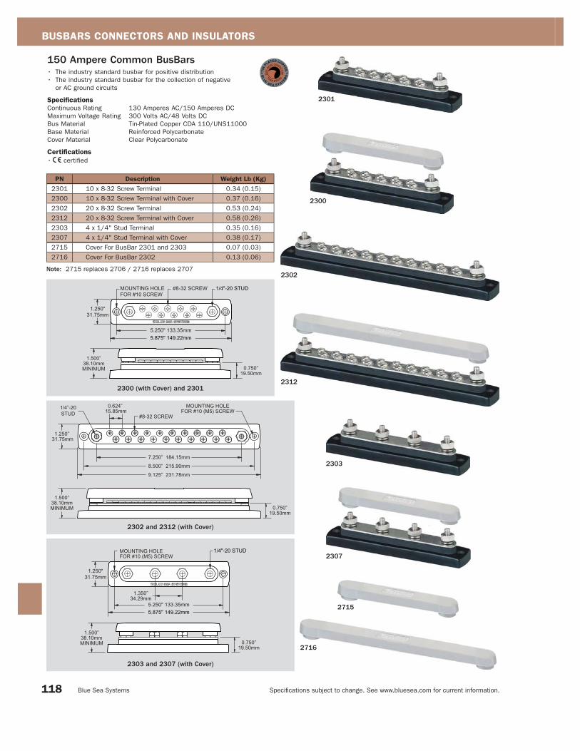
BUSBARS CONNECTORS AND INSULATORS
Specifi cations subject to change. See www.bluesea.com for current information. Blue Sea Systems
150 Ampere Common BusBars• The industry standard busbar for positive distribution
• The industry standard busbar for the collection of negative
or AC ground circuits
Specifications
Continuous Rating 130 Amperes AC/150 Amperes DC
Maximum Voltage Rating 300 Volts AC/48 Volts DC
Bus Material Tin-Plated Copper CDA 110/UNS11000
Base Material Reinforced Polycarbonate
Cover Material Clear Polycarbonate
Certifications
• E certified
PN Description Weight Lb (Kg)
2301 10 x 8-32 Screw Terminal 0.34 (0.15)
2300 10 x 8-32 Screw Terminal with Cover 0.37 (0.16)
2302 20 x 8-32 Screw Terminal 0.53 (0.24)
2312 20 x 8-32 Screw Terminal with Cover 0.58 (0.26)
2303 4 x 1/4" Stud Terminal 0.35 (0.16)
2307 4 x 1/4" Stud Terminal with Cover 0.38 (0.17)
2715 Cover For BusBar 2301 and 2303 0.07 (0.03)
2716 Cover For BusBar 2302 0.13 (0.06)
2300
2301
Note: 2715 replaces 2706 / 2716 replaces 2707
2300 (with Cover) and 23012312
2302
2302 and 2312 (with Cover)
2303 and 2307 (with Cover)
2716
2307
2303
2715
118

BUSBARS, CONNECTORS, AND INSULATORS
Specifi cations subject to change. See www.bluesea.com for current information. Catalog 2008
PN Description Weight Lb (Kg)
2105 12 x #10-32 Terminal Screws 0.80 (0.36)
2106 4 x 5/16" Stud Terminals 0.90 (0.41)
2711 Cover For MaxiBus 2105 and 2106 0.06 (0.03)
MaxiBus 250 Ampere Common BusBarsSpecifications
Continuous Amperage 250 Amperes AC/DC
Maximum Voltage Rating 300 Volts AC/48 Volts DC
Bus Material Tin-Plated Copper CDA 110/UNS11000
Base Material Reinforced Polycarbonate
Cover Material ABS
Certifications
• E certified
2105
2106
2106
2105
2711
Squalicum Harbor - Bellingham, Washington
119

BUSBARS CONNECTORS AND INSULATORS
Specifi cations subject to change. See www.bluesea.com for current information. Blue Sea Systems
PN Description Weight Lb (Kg)
2104 4 x 3/8-16 Stud Terminal 1.75 (0.79)
2107 8 x 3/8-16 Stud Terminal 2.75 (1.25)
2708 Cover For 2104 0.25 (0.11)
PowerBar 600 Ampere Common BusBarsSpecifications
Continuous Rating 545 Amperes AC/600 Amperes DC
Maximum Voltage Rating 300 Volts AC/48 Volts DC
Bus Material Tin-Plated Copper CDA 110/UNS11000
Base Material Reinforced Polycarbonate
Cover Material ABS
Certifications
• E certified
2107
2708
2104
2107
20 Ampere Terminal Blocks• Closed back design completely insulates power from the mounting surface
• Each screw pair is 1 isolated circuit
• Jumpers allow creation of common circuits (9218 - see page 122)
Specifications
Continuous Rating 20 Amperes AC/DC
Maximum Voltage Rating 300 Volts AC/DC
Bus Material Nickel-Plated Brass
Base Material Nylon
Screw Size #6
Certifications
• E certified
PN Circuit Weight Lb (Kg) [A] in" (mm) [B] Length in" (mm)
2402 2 0.05 (0.02) 1.13 (28.70) 1.41 (35.81)
2404 4 0.06 (0.03) 1.88 (47.75) 2.16 (54.86)
2406 6 0.08 (0.04) 2.63 (66.80) 2.91 (73.91)
2408 8 0.10 (0.05) 3.38 (85.85) 3.66 (92.96)
2410 10 0.11 (0.05) 4.13 (104.90) 4.41 (112.01)
2104
2406
2404
2402
2408
2410
120

BUSBARS, CONNECTORS, AND INSULATORS
Specifi cations subject to change. See www.bluesea.com for current information. Catalog 2008
PN Circuit Weight Lb (Kg) [A] in" (mm) [B] Length in" (mm)
2502 2 0.11 (0.05) 1.69 (42.93) 2.10 (53.34)
2504 4 0.15 (0.07) 2.81 (71.37) 3.22 (87.79)
2506 6 0.21 (0.10) 3.93 (99.82) 4.34 (110.24)
2508 8 0.27 (0.12) 5.05 (128.27) 5.46 (138.68)
2510 10 0.33 (0.15) 6.17 (156.72) 6.58 (167.13)
2512 12 0.35 (0.16) 7.29 (185.17) 7.70 (195.58)
30 Ampere Terminal Blocks• Closed back design completely insulates power from the mounting surface
• Each screw pair is 1 isolated circuit
• Jumpers allow creation of common circuits (9217 - see page 122)
Specifications
Continuous Rating 30 Amperes AC/DC
Maximum Voltage Rating 600 Volts AC/DC Maximum
Bus Material Nickel-Plated Brass
Base Material Phenolic
Screw Size #8
Certifications
• E certified
2506
2504
2502
2508
2510
2512
65 Ampere Terminal Blocks• Closed back design completely insulates power from the mounting surface
• Each screw pair is 1 isolated circuit
• Jumpers allow creation of common circuits (9216 - see page 122)
Specifications
Continuous Rating 65 Amperes AC/DC
Maximum Voltage Rating 600 Volts AC/DC
Bus Material Nickel-Plated Brass
Base Material Phenolic
Screw Size #10
Certifications
• E certified
PN Circuit Weight Lb (Kg) [A] in" (mm) [B] Length in" (mm)
2602 2 0.15 (0.07) 2.06 (52.32) 2.50 (63.49)
2604 4 0.25 (0.11) 3.44 (87.38) 3.88 (98.55)
2606 6 0.34 (0.16) 4.82 (122.43) 5.26 (133.61)
2608 8 0.43 (0.20) 6.20 (157.48) 6.64 (168.67)
2610 10 0.52 (0.24) 7.58 (192.53) 8.02 (203.73)
2606
2604
2602
2608
2610
121

BUSBARS CONNECTORS AND INSULATORS
Specifi cations subject to change. See www.bluesea.com for current information. Blue Sea Systems
9218
9217
9216
Terminal Block Jumpers• Jumpers allow creation of common circuits on independent connectors
• 9218–Fits 20 Ampere terminal blocks (2400 Series, page 120)
• 9217–Fits 30 Ampere terminal blocks (2500 Series, page 121)
• 9216–Fits 65 Ampere terminal blocks (2600 Series, page 121)
Specifications
Bus Material Nickel-Plated Brass
Continuous Amperage Equivalent to matching block
PN Description Weight Lb (Kg)
9218 Terminal Block Jumpers for 2400 Series 0.03 (0.01)
9217 Terminal Block Jumpers for 2500 Series 0.04 (0.02)
9216 Terminal Block Jumpers for 2600 Series 0.05 (0.03)
Terminal Feed Through ConnectorsPerfect for passing high current through hulls, decks and bulkheads. Large cables passed through holes are subject to chafing even when a protective grommet is used. Terminal Feed Through Connectors eliminate chafing and provide excellent strain relief for the cables. The large terminals have a mounting face that can be gasketed or bedded to provide a water tight installation.
Specifications
Maximum Voltage Rating 48 Volts DC Maximum
Base Material Reinforced Thermoplastic
Stud Material Tin-Plated Copper Alloy
2201
2202
2207
2208
PN Size DescriptionContinuous
AmperageColor Weight Lb (Kg)
2201 Small 5/16"-18 Stud 250A Black 0.30 (0.14)
2202 Small 5/16"-18 Stud 250A Red 0.30 (0.14)
2203 Small 3/8"-16 Stud 250A Black 0.30 (0.14)
2204 Small 3/8"-16 Stud 250A Red 0.30 (0.14)
2205 Large 3/8"-16 Stud 400A Black 0.62 (0.28)
2206 Large 3/8"-16 Stud 400A Red 0.62 (0.28)
2207 Large 1/2"-13 Stud 400A Black 0.62 (0.28)
2208 Large 1/2"-13 Stud 400A Red 0.62 (0.28)
2201–2204
2205–2208 Mounting Diagram
122

BUSBARS, CONNECTORS, AND INSULATORS
Specifi cations subject to change. See www.bluesea.com for current information. Catalog 2008
Dual PowerPost High Amperage Cable Connectors • 2015/2016/2017: are designed for connecting high amp conductors
• 2018: is designed for outboard engine installation when factory cables need to be extended
Specifications
Continuous Rating Not rated—amperage flows between terminals stacked on
post and is determined by wire and terminals used.
Maximum Voltage Rating 48 Volts DC
Base Material Reinforced PBT
Cover Material Polycarbonate
2017
PN Description Weight Lb (Kg)
2015 2 x 1/4" Studs with Cover 0.27 (0.12)
2016 2 x 5/16" Studs with Cover 0.27 (0.12)
2017 2 x 3/8" Studs with Cover 0.27 (0.12)
2018 1 x 5/16" Stud, 1 x 3/8" Stud with Cover 0.27 (0.12)
NEW PRODUCT
Available Spring, 2008
PowerPost High Amperage Cable Connectors• Connects high amperage cables securely
Specifications
Continuous Rating Not rated—amperage flows between terminals
stacked on post and is determined by wire and
terminals used.
Maximum Voltage Rating 48 Volts DC
Base Material Reinforced Thermoplastic
Certifications
• E certified
PN Description Weight Lb (Kg)
2010 #10-32 x 5/8" Stud 0.06 (0.03)
2011 1/4" x 3/4" Stud 0.10 (0.05)
2001 1/4" x 1-1/16" Stud 0.20 (0.09)
2002 5/16" x 7/8" Stud 0.25 (0.11)
2003 3/8" x 7/8" Stud 0.27 (0.12)
2010 and 2011 2001, 2002, and 2003
PowerPost Plus Cable Connectors• 150 Ampere bus allows small wire connections at high amperage
cable connections
Specifications
Bus Continuous Amperage 150 Amperes AC/DC
Voltage Rating 48 Volts DC Maximum
Bus Material Tin-Plated Copper
Base Material Reinforced
Thermoplastic
Certifications
• E certified
PN Description Weight Lb (Kg)
2101 1/4" x 1" Stud 0.29 (0.13)
2102 5/16" x 3/4" Stud 0.30 (0.14)
2103 3/8" x 3/4" Stud 0.34 (0.15)
2103
2010
2003
123
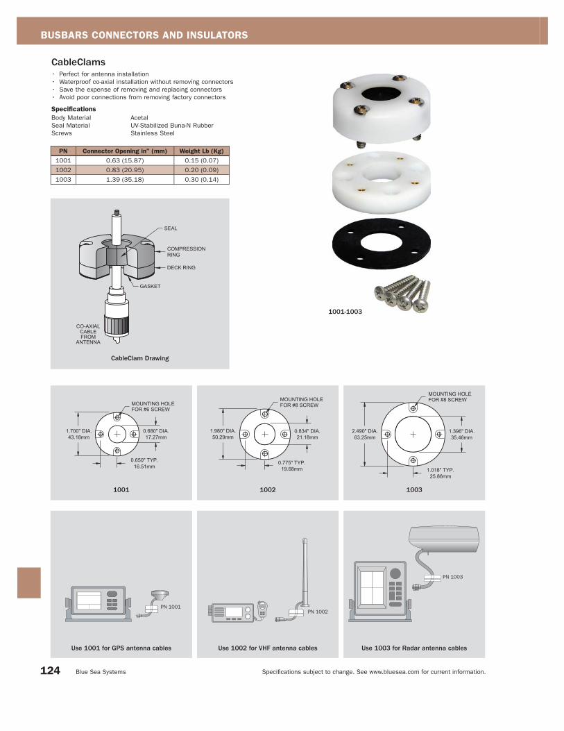
BUSBARS CONNECTORS AND INSULATORS
Specifi cations subject to change. See www.bluesea.com for current information. Blue Sea Systems
CableClams• Perfect for antenna installation
• Waterproof co-axial installation without removing connectors
• Save the expense of removing and replacing connectors
• Avoid poor connections from removing factory connectors
Specifications
Body Material Acetal
Seal Material UV-Stabilized Buna-N Rubber
Screws Stainless Steel
PN Connector Opening in" (mm) Weight Lb (Kg)
1001 0.63 (15.87) 0.15 (0.07)
1002 0.83 (20.95) 0.20 (0.09)
1003 1.39 (35.18) 0.30 (0.14)
1001 1002 1003
CableClam Drawing
1001-1003
Use 1001 for GPS antenna cables
PN 1001
Use 1002 for VHF antenna cables
PN 1002
PN 1003
Use 1003 for Radar antenna cables
124

BUSBARS, CONNECTORS, AND INSULATORS
Specifi cations subject to change. See www.bluesea.com for current information. Catalog 2008
4001
Rotating CableCaps• Top rotates 360 degrees to allow cable entry from any angle
• For batteries with integral marine wing nut posts
Specifications
Material PVC
PN Cable Size Color Package Weight Lb (Kg)
4001 All Red/Black Retail/Pair 0.25 (0.11)
9030 All Black Bulk 0.10 (0.45)
9031 All Red Bulk 0.10 (0.45)
Standard CableCaps• For batteries with marine adapter terminals added on
Specifications
Material PVC
PN Cable Size Color Package Weight Lb (Kg)
4005 4, 2, 1 Red/Black Retail/Pair 0.22 (0.10)
4006 1/0, 2/0 Red/Black Retail/Pair 0.22 (0.10)
9038 4, 2, 1 Black Bulk 0.07 (0.03)
9039 4, 2, 1 Red Bulk 0.07 (0.03)
9040 1/0, 2/0 Black Bulk 0.07 (0.03)
9041 1/0, 2/0 Red Bulk 0.07 (0.03)
4005
Automotive CableCaps• Designed to fit standard automotive posts
Specifications
Material PVC
PN Cable Size Color Package Weight Lb (Kg)
4016 4, 2, 1 Red/Black Retail 0.18 (0.08)
4017 1/0, 2/0 Red/Black Retail 0.18 (0.08)
9176 1/0, 2/0 Red Bulk 0.07 (0.03)
9177 1/0, 2/0 Black Bulk 0.07 (0.03)
4016
CableCap Stud Insulators• Insulate stud type connectors on alternators, starters, windlasses
and other high amperage devices
Specifications
Material PVC
PN Cable Size Color Package Weight Lb (Kg)
4008 18-10 Red Retail/3 0.05 (0.02)
4009 18-10 Black Retail/3 0.05 (0.02)
4010 8-4 Red Retail/2 0.05 (0.02)
4011 8-4 Black Retail/2 0.05 (0.02)
4012 2-2/0 Red Retail/1 0.07 (0.03)
4013 2-2/0 Black Retail/1 0.07 (0.03)
4014 3/0-4/0 Red Retail/1 0.07 (0.03)
4015 3/0-4/0 Black Retail/1 0.07 (0.03)
4009
4008
125

Specifi cations subject to change. See www.bluesea.com for current information. Blue Sea Systems
The DC Main Power Distribution System conducts power from the battery banks to the beginning of the DC Branch Distribution System. The three elements of the DC Power Distribution System are illustrated below:
DC Main Battery Management is made up of two product categories, Battery Switches and Charge Management, which are covered separately in this section.
Battery Switches
Purpose To isolate the potentially destructive energy in the battery banks when the boat is not in use or in emergencies.
ABYC 11.7.1.2.1. A battery switch shall be installed in the positive conductor(s) from each battery or battery bank with a CCA rating greater than
800 Amperes.
Considerations Historically there have been two types of battery switches used on boats; Single Circuit and Battery Selector Switches. In 2006,
Blue Sea Systems introduced a third option called a DUAL CIRCUIT PLUS™ Battery Switch as a better alternative.
Selecting a Battery Switch. Any battery switch used in a marine application should be UL Listed to UL Standard 1107 or should
be tested to this standard by a Nationally Recognized Testing Laboratory, of which UL is only one of many. In particular, any
amperage rating other than those determined by UL 1107, or a standard whose details are publicly stated by the manufacturer,
should be treated with skepticism. The CE mark is not a substitution for the UL 1107 Listing as the CE mark covers only the
Ignition Protection aspect of the battery switch and does not specify amperage ratings or the many other functional requirements
of UL 1107.
Battery Switch Ratings. The UL standard for marine battery switches is UL Standard 1107. This standard rates switches only
for 5 minute and 1 hour time periods. Clearly, these ratings are not useful for the boater using a switch in the engine starting
circuit where current durations may be 10 seconds or less. For this reason, Blue Sea Systems has created an additional
standard called the Engine Starting Standard. The Engine Starting Standard is 10 cycles - each consisting of an Inrush Current
spike of 1/4 second duration, a Cranking period of 9-3/4 seconds duration, and a 2 second rest period - for a total of
120 seconds. This is representative of the load imposed on a battery switch in the starting circuit under very difficult starting
conditions. Blue Sea Systems’ battery switches, in addition to being tested to UL 1107, are also tested to the Engine Starting Standard by a United States Coast Guard certified Nationally Recognized Testing Laboratory.
DC Power Distribution System
DC Main
Battery Management
DC Main
Circuit Protection
DC Branch
Power Distribution
and Circuit Protection
SI-Series ACR
DC PoweredDevices
Intermittent must be minimum 150% of continuous amperage
ContinuousIntermittent
Inrush and Cranking Starting 10 Cycle
CrankingInrush
Blue Sea Systems Engine Starting Standard UL 1107 Standard
1 2 3
1 DC Main Battery Management
House
Engine
House
Engine
126
APPENDIX - DC BATTERY MANAGEMENT AND CIRCUIT PROTECTION

Specifi cations subject to change. See www.bluesea.com for current information. Catalog 2008
Battery Isolator Automatic Charging Relay (ACR)
Battery Isolator vs. Automatic Charging Relay (ACR)
14.0
13.0
12.0
11.0
Battery Terminal
Voltage
Time10.0
1
2
3
4
1. ACR relay is open and batteries are isolated.
Voltage begins to rise slowly after engine starts or
battery charger is turned on.
2. When voltage rises to “COMBINE” voltage set on
ACR (13.5 volts in this example), ACR relay closes,
connecting and charging both batteries.
3. When engine stops or battery charger is turned off,
voltage rapidly begins falling.
4. When voltage falls to 6% less than “COMBINE”
voltage (13.5 volts - 6% = 12.7 volts in this example),
ACR relay opens isolating batteries after 1 minute.
15.0
DISCHARGE CHARGE DISCHARGE
ACR OPEN - batteries isolated.
ACR COMBINED - batteries connectedand BOTH charging.
BATTERY 1 BATTERY 2
ALTERNATOR
Charge Management
Purpose In multiple battery bank systems, Charge Management Devices (CMDs) provide a means of combining two battery banks when
charging, while keeping the battery banks isolated from each other when the charging source is not charging. This assures that
even if one battery bank is depleted there will always be a charged battery bank available for engine starting. Some devices can
also provide a means of connecting both battery banks together for additional power while starting engines. There are many
types of CMD’s that fulfi ll this role; the two main categories are Battery Isolators and Automatic Charging Relays (ACRs).
Considerations Battery Isolators. A common method of distributing charging current to multiple battery banks while assuring that they remain
electrically isolated during discharge. These devices are electrical “one way check valves” that allow current fl ow to, but not from,
the battery. Their disadvantage is that the diodes used to achieve this cause a voltage drop that consumes charging energy,
creates heat, and causes batteries to be undercharged. Alternators with external voltage sensing can correct for the
undercharging problem, but voltage drop and the heat generated remain a problem.
Automatic Charging Relays (ACRs). The popular method for achieving the same goal as isolators, but they work on a different
principle. Instead of using diodes to block current from fl owing in both directions, ACRs use mechanical relays combined
with a circuit that senses when a charging source is being applied to either battery. When a charge is being applied, the ACR
closes; and when the circuit senses that the charge is no longer present, the ACR opens after a short time delay which assures
that the ACR does not open during temporary voltage sags due to load start-ups. The most common method of determining that
a charge is being applied to the system is to sense voltages in the region above 12.6 Volts DC.
ABYC Requirements 11.7.1.2.3. Battery Switch Ratings – The intermittent rating of a battery switch shall not be less than the maximum cranking current of the
largest engine cranking motor that it serves. The minimum continuous rating of a battery switch shall be the total of the ampacities of
the main overcurrent protection devices connected to the battery switch, or the ampacity of the feeder cable to the switch, whichever is less.
ABYC Standards for battery switches are currently under review by the ABYC Project Technical Committee for battery switches. The
two major changes likely to be made are that allowable temperature rise will decrease, thereby lowering the amperage ratings that
switches currently carry, and the Engine Starting Standard developed by Blue Sea Systems will be incorporated into the standard.
When determining the proper size battery switch, consult your engine manufacturer for the amperage requirements of your engine
starter motor. If this information is not available from the engine manufacturer you may refer to the following rule of thumb used by
mechanics to roughly estimate the cranking requirement of various type and sizes of engines.
Estimating starter motor amperage draw to determine size of battery switch Gasoline engines - 1 amp/cubic inch of engine displacement = cranking rating
Diesel engines - 2 amps/cubic inch of engine displacement = cranking rating
These values are intended to be general estimates and do not apply to gear reduction starter motors. Sherman, Ed, Power Boaters
Guide to Electrical Systems, 2000
Automatic Charging Relay (ACR) Operation
BATTERY 1 BATTERY 2
ALTERNATOR
127
APPENDIX - DC BATTERY MANAGEMENT AND CIRCUIT PROTECTION

Specifi cations subject to change. See www.bluesea.com for current information. Blue Sea Systems
Purpose Fuses and circuit breakers are used to protect wire insulation from melting and starting fi res in the event of over currents or
short circuits which cause more amperage to fl ow in a wire than that wire is rated to handle. It is important to note that, except
for those wires that are intended to carry starting currents, every positive wire in the DC Main Power Distribution System
must be protected by a fuse or circuit breaker.
Considerations for DC Main Circuit Protection Mounting Placement - distance from power source. The DC Main circuit protection system uses circuit breakers or fuses to
protect the wires of the DC main distribution system. The American Boat and Yacht Council (ABYC) publishes voluntary standards
for the type and placement of the fuse or circuit breaker to be used as a DC main circuit protection device.
The diagram below shows the required placement of main circuit protection devices. Note that wire intended to carry engine
starting currents between the batteries, the switch and the starter, is not required to have main circuit protection devices installed.
Mounting placement dimensions for a fuse or circuit breaker: 7” maximum if the conductor is not housed in a sheath or enclosure in
addition to the wire insulation, 40” maximum if the conductor is housed in a sheath or enclosure in addition to the wire insulation,
72” maximum if the conductor is connected directly to the battery and housed in a sheath or enclosure in addition to the wire insulation.
Considerations when Selecting an Automatic Charging Relay Current Management. Automatic Charging Relays (ACRs) can potentially be exposed to very high currents if the engine is cranked
while the ACR is closed, paralleling the battery banks. This can occur when an alternate charge source causes the ACR to close.
Blue Sea Systems uses three methods for dealing with this. The CL-Series BatteryLink™ ACR has automatic current management
circuits, the L-Series and ML-Series ACRs have high amperage contacts rated for engine starting and Blue Sea Systems’
SI-Series ACRs momentarily opens the relay, isolating the two batteries during a starting event.
Over Voltage Adjustability. This allows the ACR to be used between different type battery banks in which one battery bank requires
lower maximum charging voltages than the other battery bank.
Combining and Disconnecting Voltage Adjustability. This allows the voltage at which the ACR closes and its associated cut-out
voltage to be adjusted for the specifi c requirements of each boat’s electrical system.
Manual Override. This allows the ACR to be manually opened, set to automatic, or manually combined from a remote location.
and DC Main Circuit Protection and Branch Circuit Protection32
Main Circuit Protection
Branch Circuits
Bilgepump
DC Main Circuits
Interior lights
Running lights
Navigation
Stereo
24-hr.Circuit
7”, 72” ABYC rule applies
7”, 40” ABYC rule applies
7”, 72” ABYC rule applies
Engine
HouseEngine starting circuits do notrequire circuit protection
Engine
House
Mounting Placement - distance from power source
Bait Pump
128
APPENDIX - DC BATTERY MANAGEMENT AND CIRCUIT PROTECTION

Specifi cations subject to change. See www.bluesea.com for current information. Catalog 2008
Selecting DC Main Circuit Protection. DC Main Circuit Protection Devices are characterized by one principal attribute, their
Ampere Interrupt Capacity (AIC) rating. Specifi cations listed in the ABYC standards determine the AIC a Main Circuit Protection
Device must have. The total Cold Cranking Amperes (CCA) of the batteries installed that can be connected to the circuit to be
protected determine the required AIC rating. See the tables below for the required AIC ratings.
* Battery cold cranking performance rating at -17.8°C (0°F) - The discharge load in amperes that a battery at -17.8°C (0°F) can deliver
for 30 seconds, and maintain a voltage of 1.2 Volts per cell or higher. e.g. 7.2 Volts for a 12 Volt battery. The CCA for the battery icons
above is an approximation and could be slightly higher or lower. Consult the battery manufacturer’s specifi cations for precise CCA ratings.
Total Connected Battery Cold Cranking Amperes (CCA) * Ampere Interrupt Capacity12 VOLTS AND 24 VOLTS
The white boxes identify two batteries, of the same size, placed in parallel confi guration. DC MAIN DC BRANCH
650 CCA or Less 1,500 AIC 750 AIC
651-1,100 CCA 3,000 AIC 1,500 AIC
Over 1,100 CCA 5,000 AIC 2,500 AIC
32 VOLTS
1,250 CCA or Less 3,000 AIC 1,500 AIC
Over 1,250 CCA 5,000 AIC 2,500 AIC
G24 G27OR
OR ORGOLFCART 8D 4D 4D
OR ORG24 G24 G27 G27 4D
ABYC standard E-11 requires that only circuit breakers be applied according to the above table and requires that the circuit breaker
can be reset and reusable. The standard does not strictly require that fuses be applied in the same way, but it is an issue to
consider, especially with high amperage fuses used to protect panel feeders or inverters. Fuses under 10 Ampere rating generally
have such a high internal resistance they prevent fault currents from reaching 1000 Amperes in 12 Volt circuits. The apparent
contradiction when using these fuses for bilge pumps and other circuits directly off the battery is less an issue than it might seem.
If a fuse blows, and the case appears to be cracked or metal has been ejected, the fuse holder should be replaced.
ABYC Interrupt Rating Table
Ampere Interrupt Capacity
(AIC)
IGNITION PROTECTED
1,000 2,000 3,000 4,000 5,000 6,000 7,000 8,000 9,000 10,000 20,000
MDL FUSE(1,000 AIC)
ATO/ATC FUSE(1,000 AIC)
SEA FUSE(2,000 AIC)
CLASS T FUSE (20,000 AIC)
ANL FUSE (6,000 AIC)
PUSH BUTTON THERMAL CIRCUIT BREAKER (3,000 AIC)
A-SERIES ROCKER Single and Double Pole MAGNETIC CIRCUIT BREAKER (5,000 AIC)
A-SERIES TOGGLE Single and Double PoleMAGNETIC CIRCUIT BREAKER (7,500 AIC)
187-SERIES THERMAL CIRCUIT BREAKER (5,000 AIC)
185-SERIES THERMAL CIRCUIT BREAKER (3,000 AIC)
AGC FUSE(1,000 AIC)
C-SERIES TOGGLE Single Pole MAGNETIC CIRCUIT BREAKER (10,000 AIC)
PN 7250I C-SERIES TOGGLE Single PoleMAGNETIC CIRCUIT BREAKER (5,000 AIC)
MAXI™ FUSE(1,000 AIC)
C-SERIES ROCKER Single PoleMAGNETIC CIRCUIT BREAKER (5,000 AIC)
Circuit Protection Device Comparison Table @ 12 Volts DC
129
APPENDIX - DC CIRCUIT PROTECTION
TERMINAL FUSE (10,000 AIC)

Specifi cations subject to change. See www.bluesea.com for current information. Blue Sea Systems
Allowable amperage for conductors under 50 VoltsReference Data
AWG
Wire
Size
Temperature Rating of Conductor Insulation
75°C (167°F) 90°C (194°F) 105°C (221°F) Metric
(Sq mm)
AWG
CM Area
SAE
CM Area
Ohms
/1000ftOutside Inside Outside Inside Outside Inside
18 10 7.5 20 16.4 20 17 0.8 1,600 1,537 6.385
16 15 11.3 25 20.5 25 21.3 1 2,600 2,336 4.016
14 20 15 30 24.6 35 29.8 2 4,100 3,702 2.525
12 25 18.8 40 32.8 45 38.3 3 6,500 5,833 1.588
10 40 30 55 45.1 60 51 5 10,500 9,343 0.9989
8 65 48.8 70 57.4 80 68 8 16,800 14,810 0.6282
6 95 71.3 100 82 120 102 13 26,600 24,538 0.3951
4 125 93.8 135 110 160 136 19 42,000 37,360 0.2485
2 170 127 180 147 210 178 32 66,500 62,450 0.1563
1 195 146 210 172 245 208 40 83,690 77,790 0.1239
0 230 172 245 200 285 242 50 105,600 98,980 0.09827
2/0 265 198 285 233 330 280 62 133,100 125,100 0.07793
3/0 310 232 330 270 385 327 81 167,800 158,600 0.06180
4/0 380 270 385 315 445 378 103 211,600 205,500 0.04901
Selecting a Fuse or Circuit Breaker. If the application requires the circuit protection device to be in an explosive area, including
gasoline engine rooms or other areas susceptible to gasoline fumes, battery compartments, or propane lockers then an ignition
protected circuit breaker or fuse is required.
1) Fuse or circuit breaker? Fuse advantages: Available in higher amperage ratings, higher interrupt ratings, greater size ranges and generally lower cost
Circuit breaker advantages: Can be reset after opening, can be used as a switch, available in waterproof models,
a wide range of opening speed characteristics are available
2) What Interrupt Rating or Ampere Interrupt Capacity (AIC) is required? See the ABYC Interrupt Rating Table on page 129. Limit the selection to a fuse or circuit breaker type that meets the AIC of each.
3) What type of circuit protection device meets the AIC rating requirements from question 2? See the Circuit Protection Device Comparison Table on page 129.
4) Does the circuit protection device need to be ignition protected?
See the icon on the Circuit Protection Device Comparison Table on page 129.
5) What should the appropriate amperage rating be for the circuit protection device? • The rating must be lower than the ampacity of the smallest wire in the circuit. See the ABYC Ampacity Rating Table below.
• The rating must be higher than the maximum continuous current that will fl ow in the circuit.
- Special considerations should be made for electrical systems that exceed 32 Volts
- There are other issues that may be considered by reading ABYC E-11.12 circuit protection
* Thermally limited amperage capacity
ABYC Ampacity* Rating Table
Considerations for General Circuit Protection Ignition Protection. ABYC E-11.5.1.3 and US Coast Guard regulations require that electrical sources of ignition located in spaces
containing gasoline powered machinery, gasoline fuel tanks, locations where fumes from gasoline or LP gas fumes can accumulate,
comply with standards for ignition protection. To be ignition protected, these devices must have any spark producing mechanisms
sealed and low enough surface temperatures that they will not ignite gas fumes. Even diesel powered vessels have suffered major
fi res and explosions as a result of fumes from dinghy fuel or stored painting supplies. Switches, circuit breakers, and fuses are all
considered to be potential sources of ignition. Many of the circuit protection devices offered by Blue Sea Systems comply with
ignition protection standards and are identifi ed on the Circuit Protection Device Comparison Table on page 129 with an icon.
Wire selection for DC applications on boats is usually based on voltage drop requirements. However, there is a maximum continuous
current that the wire can withstand without overheating. Higher grade marine wires are rated for service up to 105°C (221°F)—the ABYC
wire capacity table for 105°C is most frequently quoted. The 105°C table accurately refl ects the capacity of single conductors exposed to
freely circulating cooling air. However, other factors, such as covering bundles of wire in outer jackets to form a cable, or use of conduits
or structural voids to protect wires, can reduce the cooling and reduce the safe capacity of the wire.
A more conservative strategy is to use the 105°C wire, but treat it according to the 75°C table above when selecting circuit protection unless the wire is openly exposed for cooling.
130
APPENDIX - DC CIRCUIT PROTECTION

Specifi cations subject to change. See www.bluesea.com for current information. Catalog 2008
The AC Main Power Distribution System begins at the sources of AC power (Shore Power, Genset, or Inverter). It ends at the Line terminal connection of the AC branch circuit breaker for the Hot wire and at the branch circuit connection block for the Neutral and Safety ground wires.
Purpose • Provide a path for delivering power from the ship’s sources of AC power to the AC branch distribution system
• Provide a path for returning fault currents to ground via the green safety ground wire
• Provide a means for disconnecting AC power when the boat is not in use or in emergencies
• Provide electrical separation to insure that two sources of AC power are never connected
• Provide circuit protection for neutral and line wires in the AC main system
• Provide ground fault protection (See RCD in Glossary page 140)
Considerations Due to the nature of alternating current, the devices used to distribute AC power are frequently the same as the devices that
perform AC circuit protection. Before selecting components for an AC system, several important distinctions about AC power must
be considered.
Direct Current (DC) vs. Alternating Current (AC). In DC systems, current fl ow is in one direction - from the point of higher voltage
(electrical pressure) to lower voltage. In AC systems, the voltage reverses 60 times each second (50 times each second in Europe
and other parts of the world), called “cycles” or “Hertz” (Hz). This voltage reversal also reverses the current fl ow and gives this
type of power its name - Alternating Current (AC). Because of this alternating current and the higher voltages it uses,
(120 and 240 Volts AC vs. 12 or 24 Volts DC) the wiring confi gurations and components for AC current are different than DC.
Direct Current (DC) Alternating Current (AC)
Current or
Voltage
Time
Current or
Voltage
Time
AC Power Distribution System
ON ON AC PoweredDevices
AC Main Power Distribution and Circuit Protection
AC Main
Power Distribution
and Circuit Protection
AC Main
Source Selection
AC Branch
Power Distribution
and Circuit Protection
1 2 3
1
Direct Current vs. Alternating Current
Genset
Shore Power
131
APPENDIX - AC POWER DISTRIBUTION AND CIRCUIT PROTECTION

Specifi cations subject to change. See www.bluesea.com for current information. Blue Sea Systems
AC Wire Systems. The three most common AC systems used on boats are shown below. In all cases the ground, sometimes called
safety ground to clarify its purpose and differentiate it from the DC ground or negative, is said to be a “normally non-current carrying
wire”. Its purpose is to provide the lowest resistance path for AC currents that have strayed from their proper containment in the
normally current carrying hot and neutral wires. The ground wire is connected to the exterior conductive parts of AC devices that
could be touched by a person during normal operation and conducts errant AC currents safely to ground rather than passing them
through a human body. The ground wire is never passed through a switch or circuit breaker.
Physical Confi gurations of AC Main Circuit Breakers. Sources of AC power, whether shore power or on-board generators and
inverters, should always have a circuit breaker near the power source. This circuit breaker is designated the AC main circuit breaker.
The AC main circuit breaker should always have a pole for each of the hot and neutral wires in the circuit assuring that circuit
protection functions are not compromised in reverse polarity (page 140) situations. Therefore 120 Volt systems use a double
pole main circuit breaker. Although not required by the ABYC Standards, three pole circuit breakers with the Neutral connected
through the third pole are sometimes used on 120/240 Volt systems. In cases where the main circuit breaker is also used for
source selection the Neutral must be switched to maintain the correct Neutral connection.
Devices Qualifying as AC Main Circuit BreakersIn order to qualify as an AC main circuit breaker, four primary characteristics must be present.
1) The circuit breaker must have an Ampere Interrupt Rating (AIC) meeting those requirements of the table below:
2) The circuit breaker must be multiple pole, usually 2 or 3 (see “AC Wire Systems” above).
3) The circuit breaker must be rated for the appropriate AC system voltage in which it will be used.
4) The circuit breaker must be available in amperages appropriate to the design amperage of the system.
In the USA, this is generally 30 and 50 Amperes, while European systems are generally 16 and 32 Amperes.
AC Shore Power Source Main Circuit Breaker Branch Circuit Breaker
120V - 30A 3,000 3,000
120V - 50A 3,000 3,000
120/240V - 50A 5,000 3,000
240V - 50A 5,000 3,000
230 Volt - 50 Hz 120/240 Volt - 60 Hz120 Volt - 60 Hz
Ground
HotHot 1Hot
NeutralHot 2Neutral
GroundNeutralGround
120 Volt - 60 Hz
Main
Circuit
Breaker
120/240 Volt - 60 Hz
Main
Circuit
Breaker
230 Volt - 50 Hz
RCBO
AC Wire Systems
Physical Confi gurations of AC Main Circuit Breakers
ABYC Interrupt Rating Table
132
APPENDIX - AC POWER DISTRIBUTION AND CIRCUIT PROTECTION
European systems also require that a Residual Current Device (RCD) (page 140) be installed on the entire AC system and this is generally
implemented as Residual Current Breaker Overload (RCBO) (page 140) device which incorporates a double pole circuit breaker and an
RCD into a single device.

Specifi cations subject to change. See www.bluesea.com for current information. Catalog 2008
Purpose AC sources from shore power, generator sets, inverters, and isolation transformers must be switched in such a way that ensures
only one AC source is connected and all other AC sources are completely disconnected. Hazards to personnel and damage to
equipment can occur if sources are improperly connected to each other. A properly designed selector system will allow only the
appropriate neutral and hot source conductors to connect to the load without allowing the system to supply power backwards to
unused connections or sources.
Considerations In marine AC systems there are two common methods used to assure that two different AC sources are never connected to each
other. AC Lockout Slides are devices that slide between circuit breaker handles and allow only 1 handle to be in the “ON” position
at a time. Circuit breakers with properly confi gured slides can have different numbers of poles and different current ratings for
each breaker. AC Rotary Switches use a switching mechanism to prevent connection of different AC sources. Each system has its
advantages and disadvantages as shown below:
Follow These Steps to Select AC Circuit Protection: 1) Determine these two numbers: a. The amperage capacity of the smallest wire in the circuit to be protected. See the ABYC Ampacity Rating Table on page 130.
b. The maximum continuous current that will flow in the circuit.
2) Consult the ABYC Interrupt Rating Table on page 134 for the minimum Interrupt rating required for the application. Limit the selection to a circuit breaker type that meets the interrupt capacity requirement.
3) Select a circuit breaker amperage rating that is: a. Smaller than the amperage capacity of the smallest wire (from step 1a)
b. Larger than the maximum continuous current that will flow in the circuit (from step 1b) It is recommended that the amperage
rating be at the upper end of this range to allow for surge currents and increase in the number of devices on the circuit.
4) Verify that the voltage rating of the selected circuit breaker meets or exceeds the circuit voltage. 5) There are other issues that may be considered by reading ABYC E-11.12.2 AC Circuit Protection. See www.bluesea.com for ABYC Standards.
Ampere Interrupt Capacity (AIC) 1,000 AIC 2,000 AIC 3,000 AIC 4,000 AIC 5,000 AIC
A-SERIES ROCKER Single and Double Pole MAGNETIC CIRCUIT BREAKER (3000 AIC)
A-SERIES TOGGLE Single and Double PoleMAGNETIC CIRCUIT BREAKER (3000 AIC)
C-SERIES TOGGLE Double and Triple PoleMAGNETIC CIRCUIT BREAKER (5000 AIC)
AC Main Source Selection2
Rotary Switch Source Selector Wiring Diagram Lockout Slide Source Selector Wiring Diagram
Branch
Circuit
Breaker
Branch
Circuit
Breaker
Main
Circuit
Breaker
AC Rotary
Switch
Main
Circuit
Breaker
Main
Circuit
Breaker
Genset
Shore
Power
Genset
Shore
Power
Advantages: Compact, can handle up to 4 sources, intuitive
operation
Disadvantages: Expensive relative to lockout slides, requires
additional circuit protection
Advantages: Integrates circuit protection and source selection into
1 unit, lower cost for both circuit protection and source selection,
fl exible confi gurations for dual shore cords
Disadvantages: Requires more space, impractical for more than 3
sources
Circuit Protection Device Comparison Table @ 120 Volts AC
133
APPENDIX - AC POWER DISTRIBUTION AND CIRCUIT PROTECTION
C-SERIES ROCKER Double and Triple Pole MAGNETIC CIRCUIT BREAKER (5000 AIC)
RCBO TOGGLE and ROCKER Single and Double PoleRESIDUAL CURRENT CIRCUIT BREAKER (5000 AIC)

Specifi cations subject to change. See www.bluesea.com for current information. Blue Sea Systems
The Devices. AC branch circuit breakers are distinguished by their AIC rating. The ABYC Interrupt Rating Table below shows the
AIC required in AC branch circuit breakers for each type of shore power commonly found in marinas.
As it is only in 120 Volt and 120/240 Volt systems that AC main circuit and AC branch circuit requirements differ, the same
circuit breakers that are used in AC main systems are used in AC branch applications. It is only in the number of poles that main
and branch circuit breakers differ (See page 133 for Steps to Selecting AC Circuit Protection).
AC Shore Power Source Branch Circuit Breaker Main Circuit Breaker
120V - 30A 3,000 3,000
120V - 50A 3,000 3,000
120/240V - 50A 3,000 5,000
240V - 50A 3,000 5,000
120 Volt - 60 Hz 120/240 Volt - 60 Hz
Branch
Circuit
Breaker
Main
Circuit
Breaker
Branch
Circuit
Breaker
Main
Circuit
Breaker
230 Volt - 50 Hz (European) 120 Volt - 60 Hz (North American - Head, Galley, Engine and Deck Outlets)
Branch
Circuit
Breaker
Main
Circuit
Breaker
Branch
Circuit
Breaker
RCBO
Purpose • Distribution of high amperage currents from a single cable into lower amperages in multiple wires
• Circuit protection
• Switching
• RCBO (page 140) in North American systems
Considerations Circuit breakers used for AC branch switching and circuit protection always have one pole less than the AC main installed
between the branch circuit breaker and the AC power source. This circuit breaker is installed in the AC hot conductor.
AC Branch Power Distribution and Circuit Protection3
ABYC Interrupt Rating Table
*ABYC Requirements 11.15.3.5. If installed in a head, galley, machinery space, or on a weather deck, the receptacle shall be protected by a Type A (nominal 5
milliamperes) Ground Fault Circuit Interrupter (GFCI). (See E-11.13.)
RCBO*
134
APPENDIX - AC POWER DISTRIBUTION AND CIRCUIT PROTECTION

Specifi cations subject to change. See www.bluesea.com for current information. Catalog 2008
NUMERIC120V AC
The line to neutral voltage in a single-phase two wire
AC, not including green safety ground, system as
commonly found in the US.
240V AC
The line to line voltage in a single-phase three wire
(not including green safety ground) AC system as
commonly found in the US.
230V AC
The line to neutral voltage in a single-phase two wire
(not including green safety ground) AC system as
commonly found in Europe and many other parts of
the world.
3 phase see also Single Phase
Refers to 3 phase power generation typically 480V
AC and higher. The AC utility is a three-phase
system. In its simplest form there are three
conductors connected to three conductive coils,
which pass through a magnetic field, thus, inducing
the electrons in the wires to flow. As the polarity of
the magnetic field changes from North to South,
electrons are induced to flow first one way then the
other. This produces AC current flow. The current
that is induced in the three wires is 120° out of
phase. The current flow in the first conductor starts
120° before the second and it starts 120° before
the third. Three phase generators are only found on
the largest boats.
3 stage charging
A technique of battery charging that uses three
distinct stages to ensure a fast and complete charge
and a safe maintenance voltage. As there are
several manufacturers of multiple stage charging
systems, there is a slight difference in terminology
in the field. See each key word for a more complete
definition.
Stage 1: Charge or Bulk Mode
Stage 2: Acceptance or Absorption
Stage 3: Float
A
ABYC
American Boat and Yacht Council, a voluntary
standards-creating body for the marine industry
responsible for Standards and Recommended
Practices.
AC
see Alternating Current
AFD
see Alternator Field Disconnect
AGC Fuse
A 1-1/4 inch long x 1/4 inch diameter glass fuse
with fast blow characteristics.
AIC Amperes Interrupt Capacity
see Interrupt Rating
ATO/ATC Fuse
The blade type fuse now commonly used in the
automobile industry. It has fast blow characteristics
like the AGC fuse.
AWG (American Wire Gauge)
see also SAE Wire Gauge
AWG (American Wire Gauge) is a U.S. standard set
of non-ferrous (copper or aluminum) wire conductor
sizes. The “gauge” refers to the diameter. Typical
household wiring is AWG number 12 or 14.
Telephone wire is usually 22, 24, or 26. The higher
the gauge number, the smaller the diameter and the
thinner the wire. Thicker wire can carry more current
because it has less electrical resistance over a
given length. Also larger wire is used when the
voltage drop along its length must be minimized. For
example: High output alternator wiring might be a 2
AWG while the starter cable for a modest engine a 1
or 0 AWG.
absorption see 3 Stage Charging
see also Float Charge, Bulk, Equalization
Absorption refers to the second phase of a
multistage charging system, also called acceptance
by some manufacturers. During the absorption cycle
the battery is maintained at the maximum charging
voltage. Typically about 2.4V per cell or 14.4V for a
typical 12V system. (28.8V for a 24V system). This
is the gassing voltage for a liquid battery. Gelled
batteries are typically charged at slightly lower
voltages. The gassing voltage is also temperature
dependent. The battery cannot be maintained for
long periods of time in the absorption phase.
acceptance
see absorption
alternating current
A periodic current (sine wave) with an average value
over a cycle of zero. The current reverses at regular
intervals of time and has alternately positive and
negative values.
alternator
Commonly refers to the DC charging source on an
engine. The alternator is a three-phase AC device
that produces alternating current, which is then
rectified by a diode bridge to create direct current.
Three-phase AC devices are reliable and inexpensive
to make compared to a DC generator of the same
ampacity.
alternator field disconnect
The alternator field is created by a coil of wire
surrounded by ferrous metals. When the coil is
energized with electric current it becomes an
electro-magnet. This electromagnet is rotated,
inducing current flow in the three phase coils that
surround it. By controlling the strength of the
magnetic field, the output of the alternator may be
controlled. If the output of the alternator is open
circuited there is no place for the energy to go. The
voltage rises to a dangerous level. By disconnecting
the alternator field, the magnetic field is turned off,
thus the voltage cannot soar. This is a safety feature
on some battery switches.
ambient temperature
The temperature of the medium in which the heat of
a device is dissipated. The ambient temperature is
often specified in standards for device performance
(such as the UL Standards) as the basis for
determining the heat rise of the component.
ammeter
Ammeter measures current flow in a circuit. An
ammeter is inserted in series in the circuit. We
consider four types:
Analog
The classic analog ammeter uses the magnetic field
associated with current flow through a moving coil of
wire, to in turn move a needle over a meter face
which displays amps. This type of meter can only
measure very small current, micro-amps, before the
moving coil becomes too large to be practical. To
measure higher currents a shunt resistor is inserted
into the circuit. (see Shunt). Most of the current
flows through the shunt resistor but some passes
through a meter movement as described to read
amps when the movement is scaled appropriately.
Digital DC
The digital DC ammeter uses a shunt resistor to
measure current flow. (see Shunt). The shunt is
connected in series in the wiring of the circuit whose
current is to be measured. The shunt sense leads
are connected to the DC ammeter, which is really a
millivolt meter. The millivolt input from the shunt is
scaled to read amps per the resistance of the shunt.
For example, a current flow of 10 amps through a
100A-100mV shunt would result in a voltage of
10mV across the sense leads. A millivolt meter
would display 10, which we would interpret as 10
Amps.
Digital AC
The digital AC ammeter also uses a shunt resistor to
measure a voltage drop, which is then scaled to
read amps. The difference, however, is that the
resistor is not normally connected directly in the AC
wire of the circuit to be measured. A device called a
current transformer (CT, see Current Transformer) is
placed around the AC wire. A current is induced in
the CT, which is then passed through a load resistor.
The digital meter actually measures the voltage
across this load resistor and internally scales it to
read the appropriate number of amps.
Portable
Most portable meters today are digital and use the
same techniques of measurement as described
above. However, they are commonly limited to a few
amps when connected in series to measure current.
If high currents are to be measured, the portable
meter must use some external sensing means.
Commonly these consist of shunt resistors and
clamp-on ammeter sensors that use Hall Effect
sensors. (Operation of which are beyond the scope
of this appendix. In short, they generate a voltage,
which can be scaled to read amps just as the shunt
resistor.)
ampacity
The current carrying capacity of a conductor or
device.
ampere see Coulomb
Definition 1
The classic definition of an ampere is a unit of
electric current flow equivalent to the motion of 1
coulomb of charge, or 6.25 X 10¹⁸ electrons, past
any cross section in 1 second. This is an intuitive
way to think about an ampere. It is the flow of a
huge number of electrons through a conductor.
Definition 2
In 1948 this alternative definition was adopted: A
unit of electric current in the meter-kilogram-second
system. It is the steady current that when flowing in
straight parallel wires of infinite length and negligible
cross section, separated by a distance of one meter
in free space, produces a force between the wires of
2 x 10⁻⁷ newtons per meter of length.
ampere-hour
The electric charge transferred past a specified
circuit point by a current of one ampere in one hour.
Amp-Hour Rating (AH)
This is a common rating for batteries. This is the
total number of ampere-hours that a battery can
deliver over 20 hours at a constant rate of discharge
before the battery voltage falls below 10.5 volts.
analog
Refers to a signal or input that varies continuously
over time. Voltages and currents are analog signals,
as are temperature and pressure.
anode
The electrode of an electrochemical cell with the
more negative potential. The less noble metal of an
electrolytic cell that tends to corrode.
B
battery see also Cell
Two or more cells connected together. Thus a group
of batteries connected together can also be referred
to as a battery.
battery bank
When groups of batteries are wired in series or
parallel or a combination to increase voltage or
capacity the entire group is referred to as a battery
bank. When batteries are connected in series the
amp-hour rating is the same and the voltage is
additive. When batteries are connected in parallel
the voltage is the same and the amp-hour rating is
additive.
135
TECHNICAL GLOSSARY

Specifi cations subject to change. See www.bluesea.com for current information. Blue Sea Systems
battery state-of-charge
The term is used to describe and estimate how
much energy the battery is able to deliver. There
have been many attempts to develop improved state-
of-charge estimates. The most common methods
include: specific gravity, at-rest open-circuit voltage,
and amp-hour measurement.
battery switch rating
see Continuous Switch Rating and Intermittent Switch
Rating
battery types
AGM (Absorbed Glass Mat)
A technique for sealed lead-acid batteries. The
electrolyte is absorbed in a matrix of glass fibers,
which holds the electrolyte next to the plate, and
immobilizes it, preventing spills. AGM batteries tend
to have good power characteristics, low internal
resistance, and good behavior during charging.
Flooded
A design for lead-acid batteries. The electrolyte is an
ordinary liquid solution of sulfuric acid. Flooded cells
are prone to making gas while being charged.
Flooded cells must be periodically checked for fluid
level and water added as necessary. Flooded cells
are also typically less expensive than AGM or gel cell
type lead-acid batteries.
Gel cell
Gel or sealed lead acid batteries are basically the
same chemistry as a wet (flooded cell) battery. The
batteries’ electrolyte is in a gelatin form and is
absorbed into the plates and the battery is sealed
with epoxies. The batteries are exceptionally leak
resistant and may be used in any position. Battery
uses include UPS, emergency lights, and
camcorders. These batteries are 2 volts per cell, so
the common batteries are 4, 6, and 12 volt.
blade
That portion of a fuse to which the fuse block
connects.
bonding, cathodic
The electrical interconnection of metal objects in
common contact with water, to the engine negative
terminal, or its bus, and to the source of cathodic
protection.
branch circuit see also Main
The portion of the wiring system after the main
circuit protection device.
break (rating)
The amount of current that can be passing through a
set of contacts, such as those in a solenoid, when
they open, without damaging the contacts. This can
be a rating for a single event or over some number
of cycles, generally 1000, 10,000 or 1,000,000.
bulk
That part of a multi-stage charge regime at which
the maximum amount of current is flowing. This is
normally limited by the size of the charging source.
Lead acid batteries have the ability to accept, or
absorb, large charging currents as long as they do
not overheat or begin gassing. The bulk cycle allows
the fastest possible charge.
bus, busbar
A bus is a group of common connections, often
consisting of a strip of copper or brass with a
number of screws or bolt studs for the connection of
wires. It may be a negative or a positive bus.
C
CE (Conformité Européenné)
The CE marking is a conformity marking consisting
of the letters “CE”. The CE marking is applied to
products regulated by certain European health,
safety and environmental protection legislation. The
CE marking is obligatory for products it applies to.
The manufacturer affixes the marking certifying that
the product conforms to applicable regulations, in
order to be allowed to sell the product in the
European market.
CFR (Code of Federal Regulations)
The written regulations of the United States Federal
Government.
cathode
The electrode of an electrochemical cell with the
more positive potential. The more noble metal of an
electrolytic cell that tends not to corrode.
cell
An electrochemical system that converts chemical
energy into electrical energy. Typically consisting of
two conductive plates with different galvanic
potential immersed in an electrolyte.
cell, primary
An electrochemical device, which is discharged only
once and then, discarded.
cell, secondary
see also Battery
An electrochemical device, which may be discharged
and recharged a number of times.
charge
Classically refers to an accumulation of electrons
producing an electrostatic charge. In common use it
often refers to restoring energy to a battery.
Specifically, it would refer to the part of a multi-stage
battery charging cycle when the voltage was held
constant at or about the gassing voltage.
charge cycle
The stages through which a multi-stage charging
source restores energy to a battery. A four-stage
charge cycle includes:
bulk or charge cycle
Constant current for fast charging
acceptance or absorption cycle
Constant voltage for thorough charging
float cycle
For maintenance and long life
equalization cycle
Controlled overcharge for maximum capacity.
see key words above
circuit
A closed path of electrically, or electro-magnetically
connected, components or devices that is capable of
current flow. Typically consisting of loads, sources,
conductors, and circuit protection (circuit breakers
and fuses). For example: A battery, fuse, and bilge
pump connected together with wire are a circuit. The
path must be continuous and closed.
circuit breaker
A device that, like a fuse, interrupts current in an
electric circuit when the current becomes too high.
Unlike a fuse, a circuit breaker can be reset after it
has tripped. When high current passes through the
circuit breaker, the heat it generates or the magnetic
field it creates causes a trigger to rapidly separate
the pair of contacts that normally conduct the
current.
Circular mils
A method of specifying wire size mathematically. One
Circular Mil is a unit of area equal to that of a circle
.001” in diameter. The actual area of a Circular Mil
is:
A = π r2
A = 3.1428 x (.0005)2 inches
A = .0000007857 square inches
Class-T fuse
A very robust fuse with a 20,000 AIC. It also has
very fast response to short circuit currents.
coil
see inductor
Cold Cranking Amperes (CCA)
see also Marine Cranking Amperes
CCA is the discharge load in amps which a battery
can sustain for 30 seconds at 0° F. (-18° C) and not
fall below 1.2 volts per cell (7.2V on 12V battery).
This battery rating measures a burst of energy that
an engine needs to start in a cold environment. This
rating is used mainly for rating batteries for engine
starting capacity and does not apply to NiCad
batteries, NiMH batteries or Alkaline batteries.
common
May have more than one meaning. Typically denotes
a bus that is at ground potential most often. The
negative bus is called “the common”; sometimes
the neutral bus is also called “the common”. May
also mean a group of connections that are
connected together “in common” even though they
are at a different potential than ground.
conductivity
Conductance is the reciprocal of resistance, which
depends on the resistivity constant of the material.
Resistivity is the resistance of a conductor having
unit cross section and unit length. Conductivity is
the reciprocal of the resistivity. Its units are 1/ohm-
cm or ohm/cm, or 1/ohm-circular mils/ft.
conductor
That part of an electrical circuit whose resistance
relative to the balance of the circuit is zero. For
example, in a circuit consisting of a light bulb and a
battery, connected together with wire, the wire is
referred to as the conductor.
Conformité Européenné
see CE
continuous current
The current flow, which a device or a conductor can
carry, consume, or supply with no time limit. The
continuous current rating is normally dependent on
the temperature, since resistance increases with
temperature. For battery switches the continuous
current rating is established by testing for one hour
at the rating. This is reasonable since thermal
equilibrium would be reached within one hour.
continuous switch rating (UL 1107)
The two ratings in the UL marine battery switch
standard are Intermittent and Continuous.
Intermittent is a 5 minute rating and is based on
temperature rise of various sections of the switch as
the rated current is applied over a 5 minute period.
The Continuous rating is the same, but the time
period is 1 hour.
converter
An electrical device that converts one type of
electrical energy into another. Battery chargers
convert AC power to DC to charge the battery.
Inverters convert DC power into AC, both are
converters. Often used in RV industry to mean a
power supply that runs the domestic DC loads when
shore power is available.
coulomb see also Ampere
The measurement unit of electric charge, which is
determined by the number of electrons in excess (or
less than) the number of protons. Classically a
charge of 1 coulomb = 6.25 X 10¹⁸ electrons. The
meter-kilogram-second unit of electrical charge equal
to the quantity of charge transferred in one second
by a steady current of one ampere.
counterpoise
That portion of an antenna system composed of
wires or other types of conductor arranged in a
circular pattern at the base of the antenna at a
certain distance above ground. Insulated from the
ground, it forms the lower system of antenna
conductors.
cranking (starting)
Normally associated with “cranking current” which is
the current required by the starter circuit prior to
engine starting. The cranking current varies
significantly during the starting cycle. Initially, there
is a large surge of current required to overcome the
inertia and compression of the engine. This surge
can be two to four times the average cranking
current. Once the engine is turning there are peaks
and valleys as the pistons go through the
compression and exhaust cycles. The cranking
current rating is used for sizing batteries, cables,
and battery switches.
136
TECHNICAL GLOSSARY

Specifi cations subject to change. See www.bluesea.com for current information. Catalog 2008
current see also Amperage
Current is a flow of electrical charge carriers, usually
electrons or electron-deficient atoms. The common
symbol for current is the uppercase letter . The
standard unit is the ampere, symbolized by
A. Physicists consider current to flow from relatively
positive points to relatively negative points; this is
called conventional current or Franklin current.
Electrons, the most common charge carriers, are
negatively charged. They flow from relatively negative
points to relatively positive points.
Electric current can be either direct or
alternating. Direct current (DC) flows in the same
direction at all points in time, although the
instantaneous magnitude of the current might
vary. In an alternating current (AC), the flow of
charge carriers reverses direction periodically. The
number of complete AC cycles per second is the
frequency, which is measured in Hertz. An example
of pure DC is the current produced by an
electrochemical cell. The output of a power-supply
rectifier, prior to filtering, is an example of pulsating
DC. The output of common utility outlets is AC.
current rating
The maximum current in amperes that a device will
carry continuously under defined conditions without
exceeding specified performance limits.
current transformer see also Ammeter
The “CT”, as current transformers are commonly
referred to, is used by AC ammeters to “sense”
current flow in a wire in an AC circuit. It is a toroidal
coil of wire through which a wire whose current we
wish to measure is passed. It is normally
encapsulated and looks like a “doughnut”, which is
how electricians commonly refer to it. The doughnut
has two wires coming out of it, which are connected
to the AC ammeter. As current flows in the AC wire
we wish to measure, it induces a current flow in the
current transformer. The magnitude of the current
varies directly with the current flowing in the AC wire.
Current transformers are rated by the number of
maximum amps that can flow in the measured wire
and the current generated, by the CT, at that current
flow. For example: A 50:5 CT is rated for 50 amps
flowing in the measured wire, and it generates 5
amps of current as a consequence.
cycle
A cycle of a battery is a discharge plus a charge. For
example, if a fully charged battery has a load
applied, is then discharged and recharged, that is
one cycle. Cycle life is the total number of cycles a
battery yields.
D
DC see Direct Current
deep-cycle batteries
Batteries with thick plates to allow for reserve
energy to be stored within the battery plate and
released during slow discharge for prolonged
periods. The high-density active material remains
within the batteries’ plate/grid structure longer,
resisting the normal degradation found in cycling
conditions. Deep cycle batteries are typically used
where the battery is discharged to a great extent
and then recharged.
delay
A difference in time between the initiation of an
event and its occurrence, or between an event’s
observation and enunciation of it. This is usually
used to refer to the time between the application of
current through to a fuse or circuit breaker and the
time when the device opens.
derating
A decrease in a device’s rating, usually amperage,
due to its application in ambient conditions different
from those in which it was tested or for which it was
designed originally.
dielectric strength
The maximum voltage that a material can withstand
without allowing the two voltage potentials to short
together.
digital
A digital signal is one which has only two valid
values denoted as 1 or 0. Commonly these are
equated to distinctly different voltage. For example:
A voltage of +5V would equal a 1 and a voltage of
0V would equal a 0.
A digital meter is one that displays values as
numerical values rather than as the position of a
meter on a relative scale.
Direct Current (DC)
An electric current that always flows in the same
direction. The magnitude may vary but the current
direction is always the same. Commonly referred to
as DC. Examples of direct current sources are
batteries, fuel cells, and photo voltaic cells. DC
sources such as battery chargers and alternators
actually use rectified AC current as the source.
discharge
Refers to the consumption of energy from a battery,
or to the electrostatic discharge associated with a
lightning bolt, capacitor, etc.
double insulation system
An insulation system comprised of basic insulation
and supplementary insulation, with the two
insulations physically separated and arranged so
they are not simultaneously subjected to the same
deteriorating influences to the same degree.
double pole
Indicates a switch, relay, or circuit breaker with two
separate conductive paths, which are opened or
closed simultaneously when the device is operated.
E
Earth
The third planet from the sun in Astronomy, but in
electrical terms it refers to a connection, which is
made to a conductor that is connected to the planet
Earth. In grounded electrical systems there is a
connection, which is a copper rod or some other
highly electrically conductive connection, to the
actual Earth. This is to ensure a safe conductive
path for a short circuit, which in turn helps prevent
electrocution.
electrode
A conductive material, in an electrolyte, through
which electrical current enters or leaves.
electrolysis
Chemical changes in a solution, or electrolyte, due
to the passage of electric current.
electrolyte
A liquid in which ions are capable of migrating and,
therefore capable of conducting current. Solutions of
acids, bases, and salts in water are electrolytes.
electron see also Coulomb
An electron is a negatively charged subatomic
particle. It can be either free (not attached to any
atom), or bound to the nucleus of an atom. In
electrical conductors, current flow results from the
movement of free electrons from atom to atom
individually, and from negative to positive electric
poles in general.
The charge on a single electron is considered as the
unit electrical charge. It is assigned negative
polarity. Electrical charge quantity is not usually
measured in terms of the charge on a single
electron, because this is an extremely small
charge. Instead, the standard unit of electrical
charge quantity is the coulomb, symbolized by C,
representing about 6.25 x 10¹⁸ electrons.
Electromotive Force (EMF)
Commonly referred to as voltage, electromotive force
is the energy per unit of charge that is supplied by a
source of electrical energy such as a battery, charger
or alternator.
Electromagnetic Interference (EMI)
Noise generated by a load (typically by electrical
switching action). Usually specified as meeting
agency limits for conducted EMI (noise conducted
back onto the power bus) or radiated EMI (noise
emitted into the area surrounding a device).
energy see also Power
The classically simple definition is, the capacity to
do work. Energy may be manifested as, mechanical
motion, thermal heat, or electrical power, which is
consumed, radiated, dissipated, or stored over a
period of time. The energy in a direct-current circuit
is equal to the product of the voltage in volts, the
current in amperes, and the time in seconds. The
units for energy are Watt-hours. In alternating current
(AC) circuits, the expression for energy is more
complex.
engine negative terminal
The point at which the engine negative, generally the
engine block, is connected to the negative of the
battery.
equalization see Charge Cycle
Equalization is a controlled overcharge, which
removes lead-sulfate that is not converted during
normal charging. Equalization is best accomplished
by using a constant current of 2-7% of battery
capacity while allowing the battery voltage to rise to
its highest “natural voltage”. For a 12V battery this
can be as high as 16.2V. The equalization cycle is
continued until the specific gravity of all cells cease
to continue to rise and are approximately equal. The
equalization cycle should only be used on liquid
electrolyte batteries and only while the operator is
on the premises.
equalizer
A device wired across the same potential poles of a
multiple bank battery bank consisting of serially
wired batteries, i.e., two 12 volt batteries in series
to produce 24 volts. An equalizer maintains half its
input voltage at its output terminals. When loads are
taken off one of the batteries in the bank at that
batteries voltage, which is half of the bank voltage,
the equalizer senses that battery’s voltage is no
longer the one half the voltage of the entire bank
and the equalizer “recharges” the lower voltage
battery from the higher voltage battery.
F
fast, fast acting see also Delay
Refers to the amount of time that a fuse can endure
an over-current before blowing. Fast fuses are used
to protect sensitive equipment.
fault
A defect in the normal circuit configuration, usually
due to unintentional grounding. Commonly referred
to as a short circuit.
field
Typically refers to a magnetic field. Specifically used
when discussing the rotating electo-magnetic field
associated with an alternator. By varying the field
current, thus its strength, the output of the
alternator may be controlled.
float charge
see also Bulk, Acceptance, Equalization
A constant voltage, well below the gassing point,
that is applied to a battery to maintain its capacity.
The voltage is such that neither charging nor
discharging is occurring.
frequency see also Hertz
For an oscillating or varying current, frequency is the
number of complete cycles per second in alternating
current direction. The standard unit of frequency is
the hertz, abbreviated Hz. If a current completes one
cycle per second, then the frequency is 1 Hz; 60
cycles per second equals 60 Hz (the standard
alternating-current utility frequency).
fuse
A fuse is a safety device, consisting of a strip of low-
melting-point alloy, which is inserted in an electric
circuit to prevent excess current from flowing. If the
current becomes too high the alloy strip melts,
opening the circuit.
fusible link
A type of fuse with a replaceable conductive alloy
link that may be replaced if it “blows” due to over-
current.
137
TECHNICAL GLOSSARY

Specifi cations subject to change. See www.bluesea.com for current information. Blue Sea Systems
G
galvanic corrosion
The corrosion that occurs at the anode(s) of a
galvanic cell.
galvanic isolator
A device installed in series with the (AC) grounding
(green) conductor of the shore-power cable to
effectively block low voltage DC galvanic current flow,
but permit the passage of alternating current (AC)
normally associated with the (AC) grounding (green)
conductor. This is typically two diodes wired in
parallel facing opposite directions, sized to meet full
fault current.
galvanic compatibility chart
A list of metals and alloys arranged in order of their
potentials as measured in relation to a reference
electrode when immersed in seawater. The table of
potentials is arranged with the anodic or least noble
metals at one end, and the cathodic or most noble
metals at the other.
generator
A rotating machine capable of generating electrical
power. In the narrow definition generator refers to a
DC machine and alternator refers to an AC machine.
However, in common use the term generator is used
to refer to AC machines as well.
green wire
The green wire is the non-current carrying safety
grounding wire in an AC system in the United States.
It is connected to an exposed metal part in the
electrical system to provide a path for fault current
in the case of a short circuit.
ground fault
GFI (Ground Fault Interrupter)
GFI is a generic term referring to both GFCI and GFP
GFCI (Ground Fault Circuit Interrupter) see GFI
A device intended for the protection of personnel
that functions to de-energize a circuit, or portion
there of, within an established period of time when a
current to ground exceeds some predetermined
value that is less than that required to operate the
overcurrent protective device of the supply circuit.
GFP (Ground Fault Protector) see GFI
A device intended to protect equipment by
interrupting the electric current to the load when a
fault current to ground exceeds some predetermined
value that is less than that required to operate the
overcurrent protection device of that supply circuit.
ground, ground conductor
A point in a circuit which is at zero potential with
respect to the Earth, or which is at the lowest
potential in the system, (as with a floating ground).
grounded
The AC current carrying conductor that is
intentionally maintained at ground potential, also
called neutral.
grounding, grounding conductor
The AC conductor, not normally carrying current,
used to connect the metallic non-current carrying
parts of electrical equipment to the AC system and
engine negative terminal, or its bus, and to the
shore AC grounding conductor through the shore
power cable. This term can also refer to the normally
non-current carrying conductor used to connect
metallic non-current carrying parts of direct current
devices to the engine negative terminal, or its bus,
to minimize stray current corrosion.
ground plate
A conductive plate, commonly sintered copper, that
is placed in contact with seawater to provide a
connection to earth for a boat’s ground systems.
H
Hertz see Frequency
Hertz is a unit of frequency of one cycle per second.
It replaces the earlier term of “cycle per second
(cps).” The abbreviation for Hertz is Hz.
hot
Hot usually refers to the ungrounded current carrying
conductors in an AC system. These would typically
have a voltage of 120V or 240V in the United
States. The term Hot is also used to describe a
circuit that is energized, and has a potential greater
than ground.
I
IACS
see International Annealed Copper Standard
Impressed current
Direct current supplied by a device employing a
power source external to the electrode system of a
cathodic protection installation. The impressed
current is used to counteract the undesired galvanic
current.
inductance
An effect in electrical systems in which electrical
currents store energy temporarily in magnetic fields
before that energy is returned to the circuit.
inductor see Coil
A length of wire that is wound around a core that is
used as a storage element for a magnetic field in an
electric circuit.
inrush
The momentary steep wave front of very high current
exhibited by a load on initial application of power.
Intermittent switch rating (UL 1107)
The two ratings in the UL marine battery switch
standard are Intermittent and Continuous.
Intermittent is a 5 minute rating and is based on
temperature rise of various sections of the switch as
the rated current is applied over a 5 minute period.
The Continuous rating is the same, but the time
period is 1 hour.
International Annealed Copper Standard
Abbreviated as IACS, this is a measurement of
relative electrical conductivity that uses copper as
the standard of 100%. The expression “Brass 28
IACS” would mean that the brass under discussion
had 28% of the electrical conductivity of an
identically sized piece of copper.
interrupt rating (AIC)
The fault current that a device, normally a fuse or
circuit breaker, is capable of breaking without
damage to the circuit.
inverter
An inverter converts DC power stored in a battery to
AC power which is used by most household
appliances.
ignition protection (IP)
Devices, which operate in a potentially explosive
environment, must be ignition protected. This would
include engine rooms with gasoline engines. There is
a very specific set of tests which a device must
pass to claim ignition protection. They include
operating safely in an explosive mixture of propane
and air.
isolation transformer
A transformer that is inserted in series with the
incoming AC power to provide a magnetic coupling
for power between the ship’s systems and the AC
grid. By magnetically coupling the power there is no
direct connection by wires, which isolates the ships
AC system from the AC grid.
isolator
Refers to two or more diodes wired in parallel and
then inserted in series with the output of an
alternator. This allows for the alternator to charge
multiple batteries. The voltage drop across the
diodes can cause incomplete charging. Isolators
should not be used with alternators that use internal
voltage sensing for regulation. To be properly
installed the voltage sense lead must come from the
house battery.
J, K
kilo
A prefix in the metric system equal to 1000 times,
as in kilohertz, 1000 cycles per second.
L
line see also Load
The conductors that are at the supply of energy to a
circuit. Line normally refers to the current carrying
non-grounded conductors in an AC system.
line loss see Voltage Drop
The power loss that occurs due to amperage flowing
through the resistance of conductors over their
length.
listed (UL Listed)
Indicates that a device or component has met
certain specifications as set forth by Underwriters
Laboratory. Further, it means that the device or
component has been tested for conformance and
‘listed’ with UL so it can use the UL logo and claim
conformance to the specification.
load see also Line
A device that consumes power and does work.
load group
A collection of loads, which normally have similar
characteristics. For example the lighting circuits
might be considered a load group. Also implies that
the loads are supplied by a common bus.
lockouts (AC)
A device allowing the selection of only one source
from multiple AC sources, preventing the connection
of more than one source of AC power to a bus at the
same time.
M
magnetic
Displaying the characteristics of a magnet, including
being able to induce current flow in a conductor
when relative motion exists between them and being
able to attract ferrous materials.
main see also Branch Circuit
Refers to the main circuit breaker or bus in a power
distribution system. This is the input power source
for the system.
make (rating)
The current that a breaker, switch, or relay can
connect into without damaging the device.
make before break
Describes a switch action that connects the new
circuit before disconnecting the old. This type of
switch action is required for battery selector
switches in order to avoid an open circuit for the
engine alternator, which can cause extreme voltages
that can damage the alternator and accessory
electronics.
Marine Cranking Amperes (MCA)
MCA is the discharge load in amps, which a battery
can sustain for 30 seconds at 32°F (0° C). and not
fall below 1.2 volts per cell (7.2V on 12V battery).
This battery rating measures a burst of energy that
an engine needs to start in a cold environment.
modified sine wave
A marketing term to describe an AC waveform,
created by an inverter that is a pulse width
controlled square wave. While an improvement on
the classic square wave inverter, it is not actually a
sine wave or a close approximation.
motor circuit protection
Motors require circuit breakers or fuses that are
specifically designed for their current requirements.
This is because motors require a high initial surge of
current to get them started.
N
NEC see National Electrical Code
NEMA
National Electrical Manufacturers Association
138
TECHNICAL GLOSSARY

Specifi cations subject to change. See www.bluesea.com for current information. Catalog 2008
N-type (alternator)
An N-type alternator has a set of diodes, called the
diode trio, which supply the positive DC potential
required for the rotating field current. The actual
regulator switches the negative to achieve the proper
field strength to create the desired correct alternator
output.
National Electrical Code NEC
The NEC is developed and maintained by the
National Fire Protection Association which describes
how residential, commercial, and RV electrical
systems must be installed. The NEC is adopted,
sometimes with revision, by states that also adopt
the Uniform Building Code. Electrical inspections
required by most building permits follow the NEC.
While not required aboard boats, the NEC is a
valuable guide to safe electrical systems. The goal
of the NEC is personal safety and fire prevention.
neutral see also Single Phase
The neutral is the grounded current carrying
conductor in a single phase, four wire, 120/240V AC
system.
neutral-to-ground bonding
Connecting the ground and the neutral together via
an electrical conductor.
neutral-to-ground switching
In the US, inverter/charger installations that are
used in marine applications must have neutral-to-
ground switching. This guarantees that the neutral
and the green wire are common after the green wire
connection to neutral that is achieved through the
shore power cord no longer exists after the cord is
disconnected and shore AC is no longer serving as
the boat’s AC source. There must also be only a
single ground point in the AC system. This prevents
a voltage differential from developing between the
boat’s AC neutral and the shore or genset AC
neutral, which may cause an electric shock or
nuisance tripping of GFI’s.
non-inverter loads
Non-inverter loads are heavy loads that are not
appropriate to run from an inverter because the load
on the batteries would be excessive or illogical. They
include hot water heater, electric space heat, air
conditioning, heavy pumping loads, etc. A battery
charger that supplies the same battery as is being
used by the inverter would also be a non-inverter
load.
nuisance trip
A circuit breaker or fuse, which trips or blows without
the circuit actually being overloaded. This may be
due to weak breaker or a surge current which
requires a slow tripping breaker or a slow blow fuse.
O
ohm
The unit for resistance equals V/I = volts/amps. The
unit of resistance is the ohm, symbol Ω, the Greek
letter Omega.
Ohm’s law
States that the ratio of the EMF (Electromotive
Force) applied to a closed circuit to the current in
the circuit is a constant. That constant is the
resistance of the circuit. It may be stated as V= IR
(or E=IR, using E as the abbreviation of EMF whose
units are volts). The unit of resistance is the ohm.
open
Indicates a condition in an electric circuit in which
there is a break in the conductive path. The break
may be intentional such as an open switch or relay
or it may be unintentional such as a broken wire or a
blown fuse. In any case, the continuous conductive
path required for an electric circuit is not available.
open circuit voltage
Generally, the voltage of a source when it is not
connected to a load through an electrical circuit.
Specifically, the voltage of a battery when it is not
delivering or receiving power. A typical value for a
liquid lead acid battery is 12.8V for a fully charged
battery which has not been charged or used for 24
hours. Open circuit voltage is sometimes used as an
indicator of the state-of-charge of a battery.
The table below gives typical open circuit voltages
for both liquid and gelled electrolyte lead-acid
batteries at various states-of-charge. These voltages
should be considered approximations and may vary
according to manufacturer and the specific gravity of
the electrolyte the battery is initially filled with.
Typical Open Circuit Voltage After 24 Hours
for Liquid and Gelled Electrolyte Batteries
Percent Charge
Liquid Electrolyte
per cell voltage
Liquid Electrolyte Nominal
12V Battery
Gelled Electrolyte
per cell voltage
Gelled Electrolyte Nominal
12V Battery
100% 2.10 12.60 2.175 13.05
80% 2.09 12.54 2.13 12.78
60% 2.07 12.42 2.08 12.48
40% 2.04 12.24 2.05 12.30
20% 1.98 11.80 2.02 12.12
0% 1.95 11.70 1.98 11.88
overcurrent
When the current in a circuit exceeds the rating of
the devices or conductors in it. Fuses and circuit
breakers protect from overcurrent by opening the
circuit if such a condition exists and/or persists.
P
PE
see Protective Earth
P-type (alternator)
A P-type alternator is one which one end of the coil
which supplies the rotating magnetic field is
connected to the negative and the regulator controls
the positive side of the coil to regulate the alternator
output.
panelboard
A collection of circuit breakers, switches, and
instrumentation installed into a panel which provides
the central point for power distribution and
monitoring for the electrical system. May also refer
to a smaller panel which is located remotely from
the main panel which is used to supply loads in the
adjacent area. In the marine industry they are
usually called “panels”, or “circuit breaker panels”,
or “distribution panels”.
parallel circuit
An electrical circuit in which the positive connections
are all in common and the negative connections are
all in common. The voltage of the system appears
across each branch of the circuit. The current varies
as required by each load or source.
parallel device
A switch, solenoid, relay, or solid state device which
is used to connect multiple batteries or busses
together.
paralleling switch
Typically refers to a battery switch that allows
multiple batteries to be connected together for
engine starting. Often used to connect the battery
serving the domestic system to the engine starting
circuit for emergencies.
percent of charge
An estimate of the remaining charge in a battery.
Percent of charge is very difficult to determine
accurately without sophisticated microprocessor
based calculations.
Peukert’s equation
A formula that shows how the available capacity of a
lead-acid battery changes according to the rate of
discharge. The capacity of a battery is expressed in
Amp-Hours, but the simple formula of current times
hours does not accurately represent the situation.
Peukert found that the equation: C = In T fits the
observed behavior of batteries. “C” is the theoretical
capacity of the battery, “I” is the current, “T” is time,
and “n” is the Peukert number, a constant for the
given battery. The equation captures the fact that at
higher discharge current, there is less available
energy in the battery.
pigtail
Wires which protrude from a device to connect it to
the circuit. Often used in encapsulated products.
Sometimes refers to a method of hooking up circuits
in which a group of conductors are connected
together and then one wire is connected to the
circuit. This is done in order to simplify wiring.
plate (battery)
Flat, typically rectangular components that contain
the active material, lead or lead compound, and a
mechanical support structure called a grid, which
also has an electrical function, carrying electrons to
and from the active material. Plates are either
positive or negative, depending on the active
material they hold.
polarity
Refers to the electrical charge, which may be
positive or negative. It also refers to the positive and
negative terminals of a battery or load in a DC
system. In AC systems it refers to the connections
made to the hot and neutral. There is often a
reverse polarity light that indicates if the neutral and
hot are reversed.
polarized system
An electrical system in which the positive and
negative or the hot and neutral must be connected
in a particular way and cannot be switched.
Sometimes there are mechanical preventions to
insure the correct polarity. For example, in an AC
plug the physical configuration of the plug and
receptacle force a polarized connection.
pole
Indicates a conductive path in a switch or relay.
Switches that are single pole have one conductive
path, switches that are two pole have two conductive
paths. Also refers to the magnetic poles on an
electromagnet or a permanent magnet.
potential
The voltage across a circuit element. Implies the
potential to do work.
power
Electrical power is the rate at which electrical energy
is converted to another form, such as motion, heat,
or an electromagnetic field. The common symbol for
power is the uppercase letter P. The standard unit is
the watt, symbolized by W. In utility circuits, the
kilowatt (kW) is often specified instead; 1 kW =
1000W.
Power in a direct current (DC) circuit is equal to the
product of the voltage in volts and the current in
amperes. This rule also holds for low-frequency
alternating current (AC) circuits in which energy is
neither stored nor released. At high AC frequencies,
in which energy is stored and released (as well as
dissipated or converted), the expression for power is
more complex.
In a DC circuit, a source of V volts, delivering I
amperes, produces P watts according to the formula:
P = VI
When a current of I amperes passes through a
resistance of R ohms, then the power in watts
dissipated or converted by that component is given
by: P = I2R
When a potential difference of V volts appears
across a component having a resistance of R ohms,
then the power in watts dissipated or converted by
that component is given by: P = V2/R
139
TECHNICAL GLOSSARY
Specifi cations subject to change. See www.bluesea.com for current information. Blue Sea Systems
power factor
In AC, circuit loads other than resistance shift the
phase angle between the voltage and the current.
This shift is the result of energy being stored and
released in inductors and capacitors. Since this
storage does not represent a consumption of power,
a power measurement must take the relative phase
of voltage and current into account. The ratio of
actual power to the simple product of measured
voltage and measured current is called the power
factor. Modern electronic devices such as
microwave ovens, battery chargers, and computers
do not draw current in the same sinusoidal wave
shape as the incoming voltage. These distorted
wave shapes are also less effective at delivering
power and give rise to a power factor less than unity
because of the additional frequencies present in the
current waveform.
propagation
The transmission of an electrical or electromagnetic
signal through a medium such as air or a conductor.
Q, R
RCBO or RCCB
Residual Current Circuit Breaker is a circuit breaker
that includes an overcurrent trip mechanism like a
conventional breaker and includes a leakage current
trip that responds to current returning through a
ground path instead of the neutral conductor or
the other wires of a circuit with multiple live lines.
The principle is the same as a Ground Fault Circuit
Interrupter but RCCB’s typically have a ground fault
limit of 30mA or 100mA instead of 6mA of a GFCI
used for personnel protection. GFCI’s are generally
useful for protecting a single load or a single branch
circuit but are too sensitive for use as main circuit
breakers. RCCB’s are used for main circuit protection
in Europe for boats, houses and commercial power
distribution. Without this additional protection, as
much as 40 Amps can fl ow in the ground wire, or into
the water without tripping a conventional main circuit
breaker.
RCD see also Residual Current Device
Recreational Craft Directive - European Directive
94/25-EC relating to recreational craft.
Following are special definitions related to the RCD:
CD
Committee Draft – the first draft circulated for
comment by ISO Small Craft Technical Committee
Working Group developing the standard.
CEN
The European Committee for Standardization.
DIS
Draft International Standard – an advanced draft
where comments on the CD have been taken into
account. Minor comments accepted by the Working
Group will be incorporated in the FDIS, major
changes will result in a second circulation as a DIS.
EN
European Standard (Norme).
FDIS
Final Draft International Standard – the last voting
stage where standard bodies can only vote “yes” or
“no” and the only changes will be editorial.
ICOMIA
The International Council of Marine Industry
Associations – the International Marine Industry
Trade Association, which represents 24 national
marine industry associations. That includes virtually
all countries with an active marine industry in
Europe, North America, Asia and Australia. Its
officers and members represent its members’ views
at the EU Commission, ISO, and CEN and its
members’ representatives are actively involved in all
the RSG Standards Working Groups.
ISO
International Standards Organization
PREN
The abbreviation used by CEN to identify a draft
standard at any stage.
WG
Working Group – the committee whose members
have been nominated by their national standards
body to develop any new standard required by the
ISO Small Craft Tec. Committee (TC188) one of
whom is chosen to act as the Convenor (Chairman/
Secretary) by the TC188 members.
LIST OF EUROPEAN UNION (EU) & EUROPEAN
ECONOMIC AREA (EEA) NATIONAL STANDARDS
BODIES
Austria ON Italy UNI
Belgium IBN Luxembourg ITM
Denmark DS Netherlands NNI
Finland SFS Norway* NSF
France AFNOR Portugal IPQ
Germany DIN Spain AENOR
Greece ELOT Sweden SIS
Iceland* STRI Switzerland SNV
Ireland NSIA UK BSI
* EEA countries – whose national standards bodies
are participants in CEN debates, but have a non-
voting status.
recognized (UL recognized)
A device that is UL Recognized differs from a device
that is UL Listed. A Recognized device is expected to
be installed within a larger assembly by a
manufacturer, not in the field, and this larger
assembly is then expected to be tested by UL. The
UL Recognition then allows UL to skip testing of the
specific embedded Recognized component. UL
Recognition has little value for end users installing
devices in the field.
rectifier
A device that allows current to flow in only one
direction, such as a diode. Used to convert, or rectify
AC current into DC.
regulator (voltage regulator)
A device, which uses a feedback loop to control the
output of an alternator or other source. By
measuring the output voltage and controlling the
alternator field current, for example, the regulator is
able to continuously adjust the alternator output to
the desired voltage.
reserve capacity (battery)
RC is the number of minutes a new, fully charged
battery at 80ºF will sustain a discharge load of 25
amps to a cut-off voltage of 1.75 volts per cell
(10.5V on 12V battery). This battery rating measures
more of a continuous load on the battery.
residual current device
An RCD is an electrical safety device specially
designed to immediately switch the electricity off
when electricity is “leaking” to earth is detected at a
level harmful to electrical equipment. In most
countries using 50Hz power, an RCD is considered
to provide personnel protection.
An RCD offers a high level of personal protection
from electric shock when installed on a boat
because the additional grounding through hull
fittings is sufficient to trip and RCD during a fault.
RCD’s offer a backup level of safety if the green
ground wire of a shore cable or a galvanic isolator
has failed. Fuses or overcurrent circuit breakers do
not offer the same level of personal protection
against faults involving current flow to earth.
RCDs are designed to operate within 10 to 50
milliseconds and to disconnect the electricity
supply when they sense harmful leakage, typically
30 milliamps. See also GFI or GFCI devices which
are similar in nature, but trip at 5mA for personnel
protection. GFCI devices are required by ABYC
standards for AC outlets in galleys, on deck and in
machinery spaces. These cannot usually be used for
the entire system because normal stray currents can
cause nuisance tripping.
resistance
The opposition to the flow of current in an electric
circuit as defined by Ohm’s law. The unit of
resistance is the ohm, symbol Ω, the Greek letter
Omega.
reverse polarity
Describes a situation where the neutral and hot
wires of an AC system are reversed. Most AC panels
have an indicator to annunciate this condition, as it
can be very dangerous.
RMS (Root-mean-square)
Root-mean-square (RMS) refers to the most common
mathematical method of defining the effective
voltage or current of an AC sine wave.
To determine RMS value, three mathematical
operations are carried out on the function
representing the AC waveform:
(1) The square of the waveform function (usually a
sine wave) is determined.
(2) The function resulting from step (1) is averaged
over time.
(3) The square root of the function resulting from
step (2) is found.
In a circuit whose impedance consists of a pure
resistance, the RMS value of an AC wave is often
called the effective value or DC-equivalent value. For
example, if an AC source of 100 volts RMS is
connected across a resistor, and the resulting
current causes 50 watts of heat to be dissipated by
the resistor, then 50 watts of heat will also be
dissipated if a 100-volt DC source is connected to
the resistor.
For a sine wave, the RMS value is 0.707 times the
peak value, or 0.354 times the peak-to-peak
value. Household utility voltages are expressed in
RMS terms. A so-called “117-volt” AC circuit has a
voltage of about 165 volts peak (pk), or 330 volts
peak-to-peak (pk-pk).
S
SAE (Society of Automotive Engineers)
An organization which sets standards for various
equipment used in the automotive industry. Since
much of the basic equipment used in the marine
industry originates in the automotive industry it can
be a relevant specifications body for the marine
industry as well.
SAE wire gauge
Wire sizes as specified by the SAE, specifically for
stranded wire, similar to the AWG, see also AWG.
The same gauge in SAE wire has a smaller
conductor than in AWG wire.
sacrificial anode
A less noble metal intentionally connected to form a
galvanic cell with a more noble metal for the
purpose of protecting the more noble metal from
corrosion. Most commonly zinc.
safety green (ground) wire
The non-current carrying conductor in a three wire
120V or four wire 240V AC circuit, it provides a safe
path for fault current. See also green ground wire.
sealed lead-acid
see Gel Cell self-limiting
A device whose ability to limit output power
regardless of input power is intrinsic to its design.
sheath
A material used as a continuous protective covering
around one or more insolated conductors. The
ABYC uses this term when discussing the allowable
length of a conductor before it must have over
current protection. The distance is extended if it is
in a sheath.
shore power
AC utility power that is available when plugged into
an outlet that is supplied from the main utility
system.
short circuit
A conductive path of zero resistance. Typically refers
to an unintentional connection between two
conductors of opposite polarity. If a voltage is
applied to a short circuit the current becomes very
large and can start a fire, thus the need for short
circuit, or overcurrent, protection in the form of fuses
or circuit breakers.
140
TECHNICAL GLOSSARY
Specifi cations subject to change. See www.bluesea.com for current information. Catalog 2008
shunt
A shunt resistor is a precise, low Ohm resistor that
is temperature stable. It is used as a current
“sensor” by using a millivolt meter to measure the
voltage drop across it. Large current shunts are
commonly made of one or more strips of manganin,
a copper alloy capable of carrying high currents, that
are soldered between machined blocks of brass with
connecting bolts.
Shunts are rated according to the number of Amps
they are capable of carrying and the voltage which is
generated across the shunt when the rated current
is being passed through it. Common shunt ratings
include 100A 100mV or 500A 50mV. The resistance
can be calculated by using Ohms Law, V=IR,
50mV=500A(R), therefore R=0.1mΩ, or 0.0001Ω.
This is a very small value of resistance; it must be
in order to minimize the power loss when large
currents are flowing.
The shunt normally has two separate screws with
which the sense leads are attached. It is important
to realize that the integrity of these connections are
critical to accurate measurement and should not be
used as current carrying connections.
sine wave
A waveform that can be expressed as the graph of
the equation y = sin x. The utility AC power is a sine
wave.
single phase
The typical 120/240V AC system in the United
States is a single phase system, meaning that the
current flow in the two conductors is in phase or
that they both cross zero at the same time.
skin effect
Skin effect refers to the phenomena of conductors’
propagating AC current more efficiently on the
conductors’ surface than in its interior.
slow, slow blow see also Delay
A fuse that is a slow blow has a longer delay when
subjected to over-current, before it fails. Slow blow
fuses are required for loads that have high starting
surges, like motors.
solenoid (relay)
An electromechanical device that is used to switch
large currents. It consists of a coil of wire and a
moving contact that makes an electrical connection
when the coil of wire is energized.
source isolation (AC)
The arrangement of multiple AC power sources in
such a manner that two AC sources cannot be
connected to the same circuit simultaneously.
source selector
A switch or breaker configuration, which allows the
user to pick which source to have connected to the
bus. Typically used in AC systems with multiple
sources such as shore power and one or more
generators.
speed see Delay
Indicates how fast circuit protection devices react,
specifically with respect to other circuit breakers and
fuses.
square wave
An electrical waveform in which the current quickly
goes from zero to its peak value in a step fashion.
This is typical of inexpensive inverters.
starting bank
An arrangement of batteries that is designated for
the function of engine starting.
storage battery
An electrochemical device capable of storing energy
and releasing it and then able to be re-charged and
repeat the process.
stray current
Unwanted current flows which occur due to a partial
short circuit.
stray current corrosion
Corrosion that results when current from a battery or
other external electrical (DC) source causes a metal
in contact with an electrolyte to become anodic with
respect to another metal in contact with the same
electrolyte.
sulfation
Sulfation is the formation or deposit of lead sulfate
on the surface and in the pores of the active
material of the batteries’ lead plates. If the sulfation
becomes excessive and forms large crystals on the
plates, the battery will not operate efficiently and
may not work at all. Common causes of battery
sulfation are standing a long time in a discharged
condition, operating at excessive temperatures, and
prolonged under or over charging.
surge
A large amount of current during the initial starting
phase of a motor for example.
surge capacity
The measurement of the ability to withstand surge
currents without damage.
surge current see also Continuous Current
The pulse of current that is associated with the
initial large current required to start an electric
motor, large resistive loads, and engine cranking.
switch
An electro-mechanical device that is intended to
open an electrical circuit and thus turn a load or
source on or off.
switchboard
see Panelboard
T
terminal
A connection point or device for an electrical circuit.
A terminal strip is a series of screws which may or
may not be connected to which wires are connected.
Also refers to the connecting device
which may be crimped on the end of a wire to
enable it to be connected to the circuit with a screw,
such as a ring terminal.
terminal studs
A threaded bolt onto which ring terminals may be
placed and then fastened with a nut. Normally used
for high current connections.
thermal
In a marine context thermal most commonly refers
to a thermal circuit breaker, which uses the thermal
effect of excess current flow to create differential
expansion in a bi-metallic blade to open a circuit.
time-current curve see also Delay
A curve which depicts the relationship between the
amount of current a fuse or breaker can hold with
respect to time before opening the circuit.
tin plating
A plating of the element tin, which prevents
corrosion. Commonly used to plate copper
components such as a power bus.
toggle see also Pole
A switch which has a handle type actuator that can
be placed in, at the most, three positions.
transfer switch, AC
see source selector, Source Isolation
An electrical relay or manual switch which selects an
AC source alternative, such as a generator, shore
power, or inverter.
transformer
see Isolation Transformer
trip free
A circuit breaker designed to trip when subjected to
a fault current, even if the reset lever is held in the
ON position.
U, V
ungrounded conductor
Any conductor that is not connected to the Earth
ground system
volt (voltage)
The unit of electric potential and electromotive force,
equal to the difference of electric potential between
two points on a conducting wire carrying a constant
current of one ampere when the power dissipated
between the points is one watt.
volt-amps
The product of volts and amps, which is watts in a
DC system and the apparent power in an AC system.
voltage drop
see line loss
Wwatt
The unit of power which for a DC circuit is equal to
volts times amps.
weatherproof
Constructed or protected so that exposure to the
weather will not interfere with successful operation
in rain, spray, and splash.
wire amperage rating
The current a conductor can carry under a set of
specified conditions such as open air, in an
enclosure, and at a specified temperature.
wire sizing
The process of selecting the appropriate sized
conductor for the amount of current to be carried
while considering the length of the circuit.
withstand voltage
The maximum voltage level that can be applied
between circuits or components without causing
insulation breakdown.
X, Y, Z
141
TECHNICAL GLOSSARY

Blue Sea Systems 142
INDEX
1001 1241002 1241003 1241010 971011 971012 971013 971014 971015 971020B 241021B 241022B 241023B 241024B 241025B 241026B 241027B 241028B 241029B 241030B 241040B 251041B 251042B 251043B 251050 1081051 1081052 1081053 1081054 1081055 1081056 1091057 1091058 1091100 14–151101 14–151102 171103 171104 221105 221106 171107 171108 191109 191110 171111 171112 221113 221114 171115 171116 14–151117 14–151118 221119 221120 14–151121 14–151122 14–151123 14–151124 14–151125 14–151126 14–151127 14–151128 171129 171130 171131 191132 191133 171200 14–151201 14–151202 171203 171204 22
1205 221206 171207 171208 191209 191210 171211 171212 221213 221214 171215 171216 14–151217 14–151218 221219 221220 14–151221 14–151222 14–151223 14–151224 14–151225 14–151226 14–151227 14–151228 171229 171230 171231 191232 191233 171331 261341 261342 261343 261400 101401 101402 101403 101404 101405 101406 101407 101408 111409 111410 111411 111412 111450 121451 121452 121453 121454 121455 12–131456 12–131457 12–131458 12–131459 12–131460 12–131461 12–131462 12–131463 12–131464 12–131465 12–131466 12–131467 12–131468 12–131469 12–131470 12–131471 12–131472 161473 231474 231475 23
1476 231480 181481 181482 181483 181484 181485 181486 181487 181488 181489 181490 161491 161492 161493 161500 211501 211502 211510 251511 251512 251513 251514 251516 231517 231518 162001 1232002 1232003 1232010 1232011 1232015 1232016 1232017 1232018 1232101 1232102 1232103 1232104 1202105 1192106 1192107 1202201 1222202 1222203 1222204 1222205 1222206 1222207 1222208 1222300 1182301 1182302 1182303 1182304 1162305 1162306 1162307 1182312 1182314 1162315 1162402 1202404 1202406 1202408 1202410 1202502 1212504 1212506 1212508 1212510 1212512 121
2602 1212604 1212606 1212608 1212610 1212701 1172702 1172708 1202709 1172710 1172711 1192713 1162715 1182716 1182720 1172722 1172723 1173000 34–353001 34–353002 34–353003 34–353023 60–613025 60–613027 68–693029 68–693032 76–773043 68–693058 84–853059 84–853061 76–773068 60–613074 68–693076 68–693077 68–693079 68–693081 60–613082 60–613084 90–913085 90–913086 90–913095 90–913096 60–613097 84–853099 68–693100 213101 213102 213110 213111 213112 213127 68–693129 68–693132 76–773143 68–693158 84–853159 84–853161 76–773165 84–853174 68–693176 68–693177 68–693179 68–693184 90–913185 90–913186 90–913195 90–913197 84–853199 68–693264 60–613265 84–853375 60–613376 60–61
3377 60–613378 60–613379 60–613380 60–613381 60–613382 60–613385 60–613401 60–613402 60–613403 60–613405 68–693406 68–693407 68–693408 90–913409 68–693411 84–853412 68–693458 76–773459 76–773460 84–853461 84–853462 76–773464 68–693465 68–693466 76–773467 76–773468 76–773471 68–693473 76–773475 76–773478 84–853479 84–853480 84–853484 84–853485 68–693486 68–693488 68–693489 76–773494 76–773496 76–773498 76–773499 76–773505 68–693506 68–693507 68–693508 90–913509 68–693511 84–853512 68–693559 76–773560 84–853561 84–853562 76–773564 68–693565 68–693566 76–773567 76–773568 76–773571 68–693573 76–773575 76–773578 84–853579 84–853580 84–853584 84–853585 68–693586 68–693588 68–693589 76–773594 76–773596 76–773598 76–77
PN PAGE PN PAGE PN PAGE PN PAGE PN PAGE

Catalog 2008 143
INDEX
3599 76–774001 1254005 1254006 1254008 1254009 1254010 1254011 1254012 1254013 1254014 1254015 1254016 1254017 1254026 984027 984028 984029 984031 984100 984110 964111 27, 964112 274113 264116 274117 274125 984126 984130 984131 984135 464136 464137 464138 944140 1004150 944151 944152 944153 944154 944155 944205 100–1014206 100–1014207 100–1014208 100–1014215 100–1014216 100–1014217 100–1014218 100–1014302 584304 584306 584308 584312 584314 584316 584318 584374 56–574376 56–574384 56–574386 56–575000 515001 515002 535003 525004 525005 525006 655007 535015 635018 635021 94
5025 645026 645028 645029 645030 645031 645033 645034 645101 515102 515103 515104 515105 515106 515107 515108 515112 535113 535114 535115 535116 535117 535118 535119 535120 535121 535122 525123 525124 525125 525126 525127 525128 525129 525130 525131 525132 525133 525134 525135 525136 525137 525138 655139 655140 655141 655142 655143 655161 525162 525163 525164 525165 525175 505176 505177 505178 505180 505181 505182 505183 505184 505185 505186 505187 505188 505189 505190 505191 505235 655236 655237 65
5238 655239 655240 655241 655242 655243 655244 655245 655510 32–335511 32–336005 30–316006 30–316007 30–316010 30–316011 30–316337 806398 1006399 1007000 467002 467004 467005 467006 467007 467008 467009 467010 467011 467012 467013 467014 467015 467035 477036 477037 477038 477039 477040 477041 477042 477043 477044 477045 477046 477047 477048 477050 467051 467052 467053 467054 467055 467056 467057 467058 467059 467060 467061 467100 467102 467104 467105 467106 467107 467108 467109 467110 467111 467112 467113 467114 467115 46
7135 477136 477137 477138 477139 477140 477141 477142 477143 477144 477145 477146 477147 477148 477198 477199 477200 62, 867201 62, 867202 62, 867204 62, 867205 62, 867206 62, 867208 62, 867209 62, 867210 62, 867212 62, 867213 62, 867214 62, 867216 62, 867217 62, 867218 62, 867220 62, 867221 62, 867222 62, 867224 62, 867225 62, 867226 62, 867228 62, 867229 62, 867230 62, 867232 707233 707234 707235 707236 707237 707238 707239 707240 707241 707242 707244 48, 877246 48, 877248 48, 877250 48, 877250I 487251 727254 727256 727258 727260 707262 487263 487264 487265 487266 487267 487268 487269 487270 487271 487287 72
7288 727289 727290 727294 707295 707299 62, 867347 62, 867348 707349 707350 48, 877351 48, 877352 48, 877353 48, 877354 48, 877355 48, 877365 727370 737371 737372 737373 787374 787400 62, 877401 62, 877402 62, 877403 62, 877404 62, 877405 62, 877406 62, 877407 62, 877408 62, 877410 717411 717412 717413 717414 717415 717416 717417 717425 62, 877426 62, 877427 62, 877428 62, 877429 62, 877430 62, 877431 62, 877432 62, 877433 62, 877475 497476 497477 497480 277481 277482 277483 277484 277490 277491 277492 277493 277494 277495 277501 997502 997503 997505 997540 497541 497542 497543 497544 497545 497546 49
PN PAGE PN PAGE PN PAGE PN PAGE PN PAGE
ee

Blue Sea Systems 144
INDEX
8231 958232 958233 958234 958235 1068236 1068237 1078238 1078239 1078240 1108242 1138243 1108244 1118245 1118246 1118247 1078248 1068250 1108251 1068252 1108253 1108254 1108255 1138256 1138257 1138258 1118259 958260 958261 598262 598263 598264 60–618265 84–858266 958267 958268 958270 438271 598272 598273 598274 598275 958278 958280 368282 958283 958284 958285 958286 958287 958288 958289 958290 958291 998292 958293 958297 958298 958299 958357 798358 818359 798361 818363 808365 798366 818367 798369 808370 368371 598372 598373 59
8374 598375 60–618376 60–618377 60–618378 60–618379 60–618380 60–618381 60–618382 60–618383 978384 978385 60–618386 808401 60–618402 60–618403 60–618405 68–698406 68–698407 68–698408 90–918409 68–698410 1128411 84–858412 68–698458 76–778459 76–778460 84–858461 84–858462 76–778464 68–698465 68–698466 76–778467 76–778468 76–778471 68–698473 76–778475 76–778478 84–858479 84–858480 84–858484 84–858485 68–698486 68–698488 68–698489 76–778494 76–778496 76–778498 76–778499 76–778505 68–698506 68–698507 68–698508 90–918509 68–698511 84–858512 68–698559 76–778560 84–858561 84–858562 76–778564 68–698565 68–698566 76–778567 76–778568 76–778571 68–698573 76–778575 76–778578 84–858579 84–858580 84–858584 84–85
8585 68–698586 68–698588 68–698589 76–778594 76–778596 76–778598 76–778599 76–778686 378687 378689 378690 378691 378693 379001 32–339002 32–339003 32–339004 32–339009 799010 819011 799012 389019 809030 1259031 1259038 1259039 1259040 1259041 1259077 819093 809112 439159 309176 1259177 1259216 1229217 1229218 1229228 1139229 1139230 1139231 1139233 1139353 1119354 1119630 1115510 200 32–335511 200 32–336005200 30–316006200 30–316007200 30–316010200 30–316011200 30–317900200 307901200 309001 200 32–339002 200 32–339003 200 32–339004 200 32–33
7547 497548 497549 497551 497554 497560 737561 737562 737563 737564 737565 737566 737567 737568 737570 717571 717572 717573 717574 717575 717576 717577 717580 737581 737582 737583 737584 737585 737586 737587 737588 737600 407610 417620 427621 427650 407700 397701 397702 397703 397900 307901 307902 30, 32, 34 8003 1108005 1108013 1128014 1128015 1128016 1108017 1108018 1108019 1108022 1108023 60–618025 60–618027 68–698028 1108029 68–698030 100–1018031 100–1018032 76–778033 978034 978035 968037 968038 1108039 100–1018041 1108043 68–698051 1128053 598054 59
8058 84–858059 84–858061 76–778065 978066 978067 100–1018068 60–618069 978072 868073 1138074 68–698076 68–698077 68–698079 68–698080 368081 60–618082 60–618084 90–918085 90–918086 90–918087 49, 728088 49, 728089 49, 728095 90–918096 60–618097 84–858099 68–698110 1128127 68–698129 68–698132 76–778134 978143 68–698158 84–858159 84–858161 76–778165 84–858166 978167 978169 978171 978172 978173 708174 68–698176 68–698177 68–698179 68–698184 90–918185 90–918186 90–918195 90–918197 84–858199 68–698200 968204 968205 968206 968207 968208 96, 998209 968210 968211 968212 968214 1008216 998217 1008218 958219 958220 958221 958222 958230 95
PN PAGE PN PAGE PN PAGE PN PAGE PN PAGE
eeee
ee
eeee