Block 9 Safety Valves
85
The Steam and Condensate Loop 9.1.1 Block 9 Safety Valves Introduction to Safety Valves Module 9.1 Module 9.1 Introduction to Safety Valves SC-GCM-68 CM Issue 2 © Copyright 2005 Spirax-Sarco Limited
-
Upload
babu-aravind -
Category
Documents
-
view
48 -
download
2
description
safety valves
Transcript of Block 9 Safety Valves

The Steam and Condensate Loop 9.1.1
Block 9 Safety Valves Introduction to Safety Valves Module 9.1
Module 9.1Introduction to Safety Valves
SC-G
CM-6
8 C
M Is
sue
2 ©
Cop
yri
ght
20
05
Sp
irax-S
arc
o L
imit
ed
The Steam and Condensate Loop9.1.2
Block 9 Safety Valves Introduction to Safety Valves Module 9.1
Introduction
As soon as mankind was able to boil water to create steam, the necessity of the safety devicebecame evident. As long as 2000 years ago, the Chinese were using cauldrons with hinged lids toallow (relatively) safer production of steam. At the beginning of the 14th century, chemists usedconical plugs and later, compressed springs to act as safety devices on pressurised vessels.
Early in the 19th century, boiler explosions on ships and locomotives frequently resulted fromfaulty safety devices, which led to the development of the first safety relief valves.
In 1848, Charles Retchie invented the accumulation chamber, which increases the compressionsurface within the safety valve allowing it to open rapidly within a narrow overpressure margin.Today, most steam users are compelled by local health and safety regulations to ensure that theirplant and processes incorporate safety devices and precautions, which ensure that dangerousconditions are prevented.
The primary function of a safety valve is therefore to protect life and property.
The principle type of device used to prevent overpressure in plant is the safety or safety reliefvalve. The safety valve operates by releasing a volume of fluid from within the plant when apredetermined maximum pressure is reached, thereby reducing the excess pressure in a safemanner. As the safety valve may be the only remaining device to prevent catastrophic failureunder overpressure conditions, it is important that any such device is capable of operating at alltimes and under all possible conditions.
Safety valves should be installed wherever the maximum allowable working pressure (MAWP) ofa system or pressure-containing vessel is likely to be exceeded. In steam systems, safety valvesare typically used for boiler overpressure protection and other applications such as downstreamof pressure reducing controls. Although their primary role is for safety, safety valves are also usedin process operations to prevent product damage due to excess pressure. Pressure excess can begenerated in a number of different situations, including:
o An imbalance of fluid flowrate caused by inadvertently closed or opened isolation valves on aprocess vessel.
o Failure of a cooling system, which allows vapour or fluid to expand.
o Compressed air or electrical power failure to control instrumentation.
o Transient pressure surges.
o Exposure to plant fires.
o Heat exchanger tube failure.
o Uncontrollable exothermic reactions in chemical plants.
o Ambient temperature changes.
The terms �safety valve� and �safety relief valve� are generic terms to describe many varieties ofpressure relief devices that are designed to prevent excessive internal fluid pressure build-up. Awide range of different valves is available for many different applications and performance criteria.Furthermore, different designs are required to meet the numerous national standards that governthe use of safety valves.
A listing of the relevant national standards can be found at the end of this module.
In most national standards, specific definitions are given for the terms associated with safety andsafety relief valves. There are several notable differences between the terminology used in theUSA and Europe. One of the most important differences is that a valve referred to as a �safetyvalve� in Europe is referred to as a �safety relief valve� or �pressure relief valve� in the USA. Inaddition, the term �safety valve� in the USA generally refers specifically to the full-lift type ofsafety valve used in Europe.
The Steam and Condensate Loop 9.1.3
Block 9 Safety Valves Introduction to Safety Valves Module 9.1
DIN
The ASME / ANSI PTC25.3 standards applicable to the USA define the following generic terms:
o Pressure relief valve - A spring-loaded pressure relief valve which is designed to open torelieve excess pressure and to reclose and prevent the further flow of fluid after normalconditions have been restored. It is characterised by a rapid-opening �pop� action or by openingin a manner generally proportional to the increase in pressure over the opening pressure. Itmay be used for either compressible or incompressible fluids, depending on design, adjustment,or application.
This is a general term, which includes safety valves, relief valves and safety relief valves.
o Safety valve - A pressure relief valve actuated by inlet static pressure and characterised byrapid opening or pop action.
Safety valves are primarily used with compressible gases and in particular for steam and airservices. However, they can also be used for process type applications where they may beneeded to protect the plant or to prevent spoilage of the product being processed.
o Relief valve - A pressure relief device actuated by inlet static pressure having a gradual liftgenerally proportional to the increase in pressure over opening pressure.
Relief valves are commonly used in liquid systems, especially for lower capacities and thermalexpansion duty. They can also be used on pumped systems as pressure overspill devices.
o Safety relief valve - A pressure relief valve characterised by rapid opening or pop action, orby opening in proportion to the increase in pressure over the opening pressure, dependingon the application, and which may be used either for liquid or compressible fluid.
In general, the safety relief valve will perform as a safety valve when used in a compressiblegas system, but it will open in proportion to the overpressure when used in liquid systems, aswould a relief valve.
The European standards (BS 6759 and DIN 3320) provide the following definition:
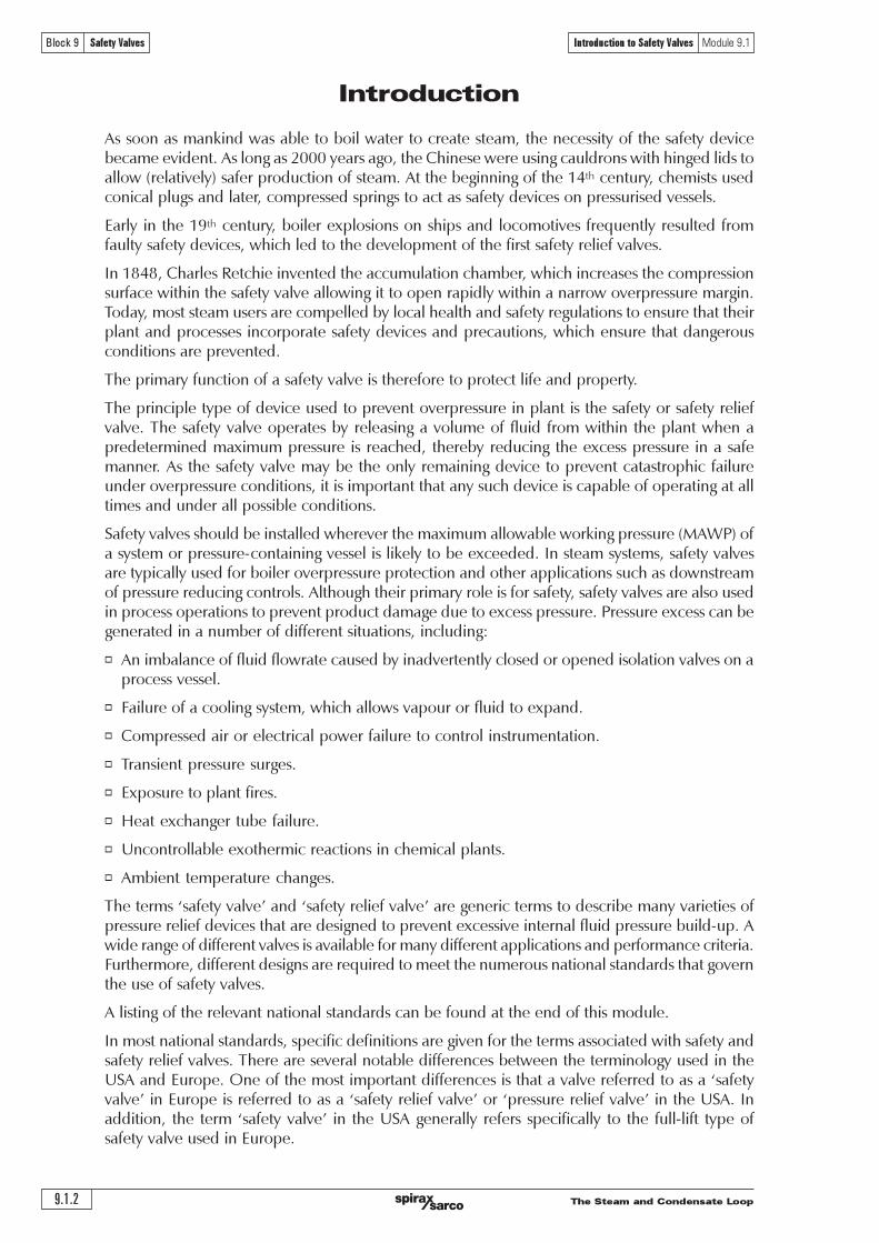
o Safety valve - A valve which automatically, without the assistance of any energy other thanthat of the fluid concerned, discharges a certified amount of the fluid so as to prevent apredetermined safe pressure being exceeded, and which is designed to re-close and preventthe further flow of fluid after normal pressure conditions of service have been restored.
Typical examples of safety valves used on steam systems are shown in Figure 9.1.1.
Fig. 9.1.1 Typical safety valves
ASME
The Steam and Condensate Loop9.1.4
Block 9 Safety Valves Introduction to Safety Valves Module 9.1
Cap
Springadjuster
Spring
Springhousing (bonnet)
Body
Upperblowdown ring
Disc
Lowerblowdown ring
Seat
Inlet tract(approach channel)
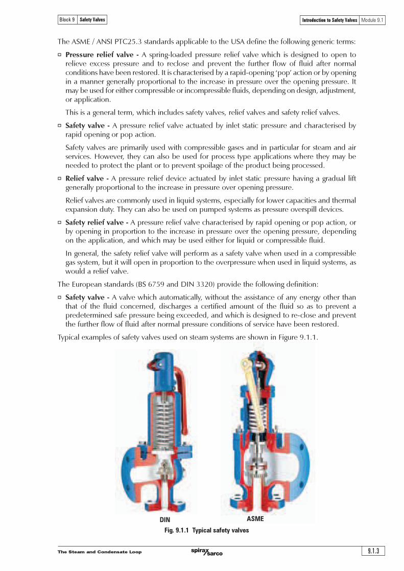
Fig. 9.1.2 Typical safety valve designs
Safety valve design
The basic spring loaded safety valve, referred to as �standard� or �conventional� is a simple,reliable self-acting device that provides overpressure protection.
The basic elements of the design consist of a right angle pattern valve body with the valve inletconnection, or nozzle, mounted on the pressure-containing system. The outlet connection maybe screwed or flanged for connection to a piped discharge system. However, in some applications,such as compressed air systems, the safety valve will not have an outlet connection, and the fluidis vented directly to the atmosphere.
Typical ASME valve
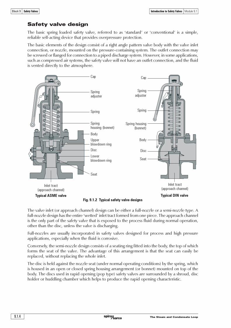
The valve inlet (or approach channel) design can be either a full-nozzle or a semi-nozzle type. Afull-nozzle design has the entire �wetted� inlet tract formed from one piece. The approach channelis the only part of the safety valve that is exposed to the process fluid during normal operation,other than the disc, unless the valve is discharging.
Full-nozzles are usually incorporated in safety valves designed for process and high pressureapplications, especially when the fluid is corrosive.
Conversely, the semi-nozzle design consists of a seating ring fitted into the body, the top of whichforms the seat of the valve. The advantage of this arrangement is that the seat can easily bereplaced, without replacing the whole inlet.
The disc is held against the nozzle seat (under normal operating conditions) by the spring, whichis housed in an open or closed spring housing arrangement (or bonnet) mounted on top of thebody. The discs used in rapid opening (pop type) safety valves are surrounded by a shroud, discholder or huddling chamber which helps to produce the rapid opening characteristic.
Typical DIN valve
Cap
Spring
adjuster
Spring
Spring housing(bonnet)
Body
Disc
Seat
Inlet tract(approach channel)
The Steam and Condensate Loop 9.1.5
Block 9 Safety Valves Introduction to Safety Valves Module 9.1
(a) (b)
The closing force on the disc is provided by a spring, typically made from carbon steel. Theamount of compression on the spring is usually adjustable, using the spring adjuster, to alter thepressure at which the disc is lifted off its seat.
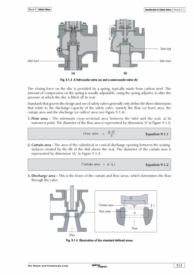
Standards that govern the design and use of safety valves generally only define the three dimensionsthat relate to the discharge capacity of the safety valve, namely the flow (or bore) area, thecurtain area and the discharge (or orifice) area (see Figure 9.1.4).
1. Flow area - The minimum cross-sectional area between the inlet and the seat, at itsnarrowest point. The diameter of the flow area is represented by dimension �d� in Figure 9.1.4.
2. Curtain area - The area of the cylindrical or conical discharge opening between the seatingsurfaces created by the lift of the disk above the seat. The diameter of the curtain area isrepresented by dimension �d1� in Figure 9.1.4.
3. Discharge area - This is the lesser of the curtain and flow areas, which determines the flowthrough the valve.
Equation 9.1.1 !"
#$%& '()'
*
Equation 9.1.2
!
!"#$%&'$"($ ' ') *'
Seat ring
Inlet tract
Fig. 9.1.4 Illustration of the standard defined areas
Curtain area
Flow area
d1
d
L
Fig. 9.1.3 A full-nozzle valve (a) and a semi-nozzle valve (b)
Flow
Flow
Inlet tract
The Steam and Condensate Loop9.1.6
Block 9 Safety Valves Introduction to Safety Valves Module 9.1
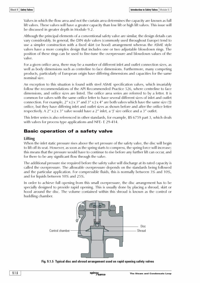
Fig. 9.1.5 Typical disc and shroud arrangement used on rapid opening safety valves
Valves in which the flow area and not the curtain area determines the capacity are known as fulllift valves. These valves will have a greater capacity than low lift or high lift valves. This issue willbe discussed in greater depth in Module 9.2.
Although the principal elements of a conventional safety valve are similar, the design details canvary considerably. In general, the DIN style valves (commonly used throughout Europe) tend touse a simpler construction with a fixed skirt (or hood) arrangement whereas the ASME stylevalves have a more complex design that includes one or two adjustable blowdown rings. Theposition of these rings can be used to fine-tune the overpressure and blowdown values of thevalve.
For a given orifice area, there may be a number of different inlet and outlet connection sizes, aswell as body dimensions such as centreline to face dimensions. Furthermore, many competingproducts, particularly of European origin have differing dimensions and capacities for the samenominal size.
An exception to this situation is found with steel ASME specification valves, which invariablyfollow the recommendations of the API Recommended Practice 526, where centreline to facedimensions, and orifice sizes are listed. The orifice area series are referred to by a letter. It iscommon for valves with the same orifice letter to have several different sizes of inlet and outletconnection. For example, 2� x J x 3� and 3� x J x 4� are both valves which have the same size (�J)orifice, but they have differing inlet and outlet sizes as shown before and after the orifice letterrespectively. A 2� x J x 3� valve would have a 2� inlet, a �J� size orifice and a 3� outlet.
This letter series is also referenced in other standards, for example, BS 6759 part 3, which dealswith valves for process type applications and NFE- E 29-414.
Basic operation of a safety valve
LiftingWhen the inlet static pressure rises above the set pressure of the safety valve, the disc will beginto lift off its seat. However, as soon as the spring starts to compress, the spring force will increase;this means that the pressure would have to continue to rise before any further lift can occur, andfor there to be any significant flow through the valve.
The additional pressure rise required before the safety valve will discharge at its rated capacity iscalled the overpressure. The allowable overpressure depends on the standards being followedand the particular application. For compressible fluids, this is normally between 3% and 10%,and for liquids between 10% and 25%.
In order to achieve full opening from this small overpressure, the disc arrangement has to bespecially designed to provide rapid opening. This is usually done by placing a shroud, skirt orhood around the disc. The volume contained within this shroud is known as the control orhuddling chamber.
Control chamber
Disc
Shroud
The Steam and Condensate Loop 9.1.7
Block 9 Safety Valves Introduction to Safety Valves Module 9.1
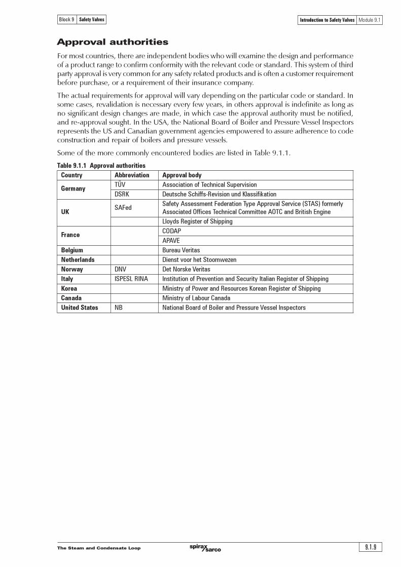
Fig. 9.1.7 Relationship between pressure and lift for a typical safety valve
Maximum discharge
Blowdown Overpressure
Closing
10%
% lift
100%
Opening
10%Reseat
Set pressure
Popaction
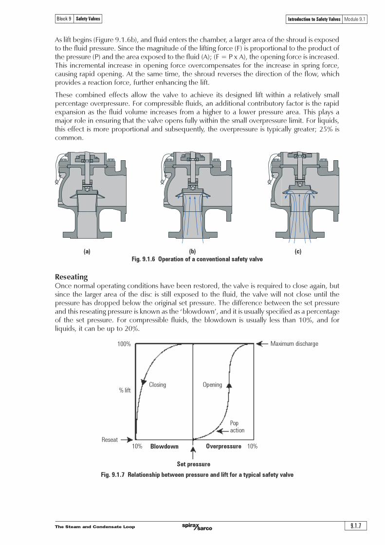
As lift begins (Figure 9.1.6b), and fluid enters the chamber, a larger area of the shroud is exposedto the fluid pressure. Since the magnitude of the lifting force (F) is proportional to the product ofthe pressure (P) and the area exposed to the fluid (A); (F = P x A), the opening force is increased.This incremental increase in opening force overcompensates for the increase in spring force,causing rapid opening. At the same time, the shroud reverses the direction of the flow, whichprovides a reaction force, further enhancing the lift.
These combined effects allow the valve to achieve its designed lift within a relatively smallpercentage overpressure. For compressible fluids, an additional contributory factor is the rapidexpansion as the fluid volume increases from a higher to a lower pressure area. This plays amajor role in ensuring that the valve opens fully within the small overpressure limit. For liquids,this effect is more proportional and subsequently, the overpressure is typically greater; 25% iscommon.
(a) (b) (c)
Fig. 9.1.6 Operation of a conventional safety valve
ReseatingOnce normal operating conditions have been restored, the valve is required to close again, butsince the larger area of the disc is still exposed to the fluid, the valve will not close until thepressure has dropped below the original set pressure. The difference between the set pressureand this reseating pressure is known as the �blowdown�, and it is usually specified as a percentageof the set pressure. For compressible fluids, the blowdown is usually less than 10%, and forliquids, it can be up to 20%.

The Steam and Condensate Loop9.1.8
Block 9 Safety Valves Introduction to Safety Valves Module 9.1
The design of the shroud must be such that it offers both rapid opening and relatively smallblowdown, so that as soon as a potentially hazardous situation is reached, any overpressure isrelieved, but excessive quantities of the fluid are prevented from being discharged. At the sametime, it is necessary to ensure that the system pressure is reduced sufficiently to prevent immediatereopening.
The blowdown rings found on most ASME type safety valves are used to make fine adjustmentsto the overpressure and blowdown values of the valves (see Figure 9.1.8). The lower blowdown(nozzle) ring is a common feature on many valves where the tighter overpressure and blowdownrequirements require a more sophisticated designed solution. The upper blowdown ring is usuallyfactory set and essentially takes out the manufacturing tolerances which affect the geometry ofthe huddling chamber.
The lower blowdown ring is also factory set to achieve the appropriate code performancerequirements but under certain circumstances can be altered. When the lower blowdown ring isadjusted to its top position the huddling chamber volume is such that the valve will pop rapidly,minimising the overpressure value but correspondingly requiring a greater blowdown before thevalve re-seats. When the lower blowdown ring is adjusted to its lower position there is minimalrestriction in the huddling chamber and a greater overpressure will be required before the valveis fully open but the blowdown value will be reduced.
Fig. 9.1.8 The blowdown rings on an ASME type safety valve
Upper adjusting pin
Lower adjusting pin
Upper adjusting ring
Lower adjusting ring
The Steam and Condensate Loop 9.1.9
Block 9 Safety Valves Introduction to Safety Valves Module 9.1
Approval authorities
For most countries, there are independent bodies who will examine the design and performanceof a product range to confirm conformity with the relevant code or standard. This system of thirdparty approval is very common for any safety related products and is often a customer requirementbefore purchase, or a requirement of their insurance company.
The actual requirements for approval will vary depending on the particular code or standard. Insome cases, revalidation is necessary every few years, in others approval is indefinite as long asno significant design changes are made, in which case the approval authority must be notified,and re-approval sought. In the USA, the National Board of Boiler and Pressure Vessel Inspectorsrepresents the US and Canadian government agencies empowered to assure adherence to codeconstruction and repair of boilers and pressure vessels.
Some of the more commonly encountered bodies are listed in Table 9.1.1.
Table 9.1.1 Approval authorities
Country Abbreviation Approval body
GermanyTÜV Association of Technical Supervision
DSRK Deutsche Schiffs-Revision und Klassifikation
SAFedSafety Assessment Federation Type Approval Service (STAS) formerly
UK Associated Offices Technical Committee AOTC and British Engine
Lloyds Register of Shipping
FranceCODAP
APAVE
Belgium Bureau Veritas
Netherlands Dienst voor het Stoomwezen
Norway DNV Det Norske Veritas
Italy ISPESL RINA Institution of Prevention and Security Italian Register of Shipping
Korea Ministry of Power and Resources Korean Register of Shipping
Canada Ministry of Labour Canada
United States NB National Board of Boiler and Pressure Vessel Inspectors

The Steam and Condensate Loop9.1.10
Block 9 Safety Valves Introduction to Safety Valves Module 9.1
Codes and Standards
Standards relevant to safety valves vary quite considerably in format around the world, andmany are sections within codes relevant to Boilers or Pressure Containing Vessels. Some will onlyoutline performance requirements, tolerances and essential constructional detail, but give noguidance on dimensions, orifice sizes etc. Others will be related to installation and application.It is quite common within many markets to use several in conjunction with each other.
Table 9.1.2 Standards relating to safety valves
Country Standard No. Description
AD-Merkblatt A2Pressure Vessel Equipment safety devicesagainst excess pressure - safety valves
GermanyTRD 421
Technical Equipment for Steam Boilers Safeguards against excessivepressure - safety valves for steam boilers of groups I, IlI & IV
TRD 721Technical Equipment for Steam Boilers Safeguards against excessivepressure - safety valves for steam boilers of group II
Part 1 specification for safety valves for steam and hot waterUK BS 6759 Part 2 specification for safety valves for compressed air or inert gas
Part 3 specification for safety valves for process fluids
AFNOR NFE-ESafety and relief valves
France 29-411 to 416
NFE-E 29-421 Safety and relief valves
Korea KS B 6216 Spring loaded safety valves for steam boilers and pressure vessels
Japan JIS B 8210 Steam boilers and pressure vessels - spring loaded safety valves
Australia SAA AS1271Safety valves, other valves, liquid level gauges and other fittings forboilers and unfired pressure vessels
ASME I Boiler Applications
ASME III Nuclear Applications
ASME VIII Unfired Pressure Vessel Applications
ANSI/ASMESafety and Relief Valves - performance test codes
PTC 25.3
USA Sizing selection and installation of pressure-relieving devices in refineries
API RP 520 Part 1 Design
Part 2 Installation
API RP 521 Guide for pressure relieving and depressurising systems
API STD 526 Flanged steel pressure relief valves
API STD 527 Seat tightness of pressure relief valves
Europe prEN ISO 4126* Safety devices for protection against excessive pressure
International ISO 4126 Safety valves - general requirements
*Note: pr = pre-ratification. This harmonised European standard is not offically issued.
For steam boiler applications there are very specific requirements for safety valve performance,demanded by national standards and often, insurance companies. Approval by an independentauthority is often necessary, such as British Engine, TÜV or Lloyd�s Register.
Safety valves used in Europe are also subject to the standards associated with the PressureEquipment Directive (PED). Being classified as �Safety accessories�, safety valves are consideredas �Category 4� equipment, which require the most demanding level of assessment within thePED regime. This can usually be met by the manufacturer having an ISO 9000 quality systemand the safety valve design and performance certified by an officially recognised approval authorityreferred to as a �Notified Body�.

The Steam and Condensate Loop 9.1.11
Block 9 Safety Valves Introduction to Safety Valves Module 9.1
Questions
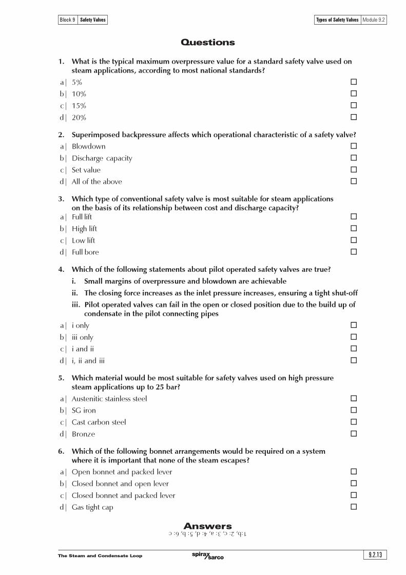
1. What is the primary function of a safety valve?
a| To maintain the pressure of a system within a specified range. ¨
b| To protect life and property ¨
c| To prevent product spoilage ¨
d| To allow the gradual release of overpressure ¨
2. What is the main operational difference between safety valves and relief valves?
a| Relief valves are characterised by a rapid opening or �popping� type lift characteristic ¨
b| Safety valves are characterised by a gradual opening type lift characteristic ¨
c| Relief valves are characterised by a gradual opening type lift characteristic ¨
d| Safety valves will have a rapid opening lift characteristic when used on compressiblefluid systems and a gradual opening characteristic when used on liquid systems ¨
3. Given the safety valve dimensions as indicated in the illustration below,what would the discharge area of the safety valve be?
Given:d = 29 mm
d1 = 35 mmL = 5 mm
a| 550 mm2 ¨
b| 617 mm2 ¨
c| 661 mm2 ¨
d| 693 mm2 ¨
4. Which of the following factors combine to produce the rapid openingcharacteristic of most safety valves used in steam applications?
a| The rapid expansion of the steam as the fluid volume increases ¨
b| Exposure of a greater disc surface area to the steam ¨
c| The vectoring effect created by the shroud ¨
d| All of the above ¨
Curtain area
Flow area
d1
d
L
Flow
Flow
The Steam and Condensate Loop9.1.12
Block 9 Safety Valves Introduction to Safety Valves Module 9.1
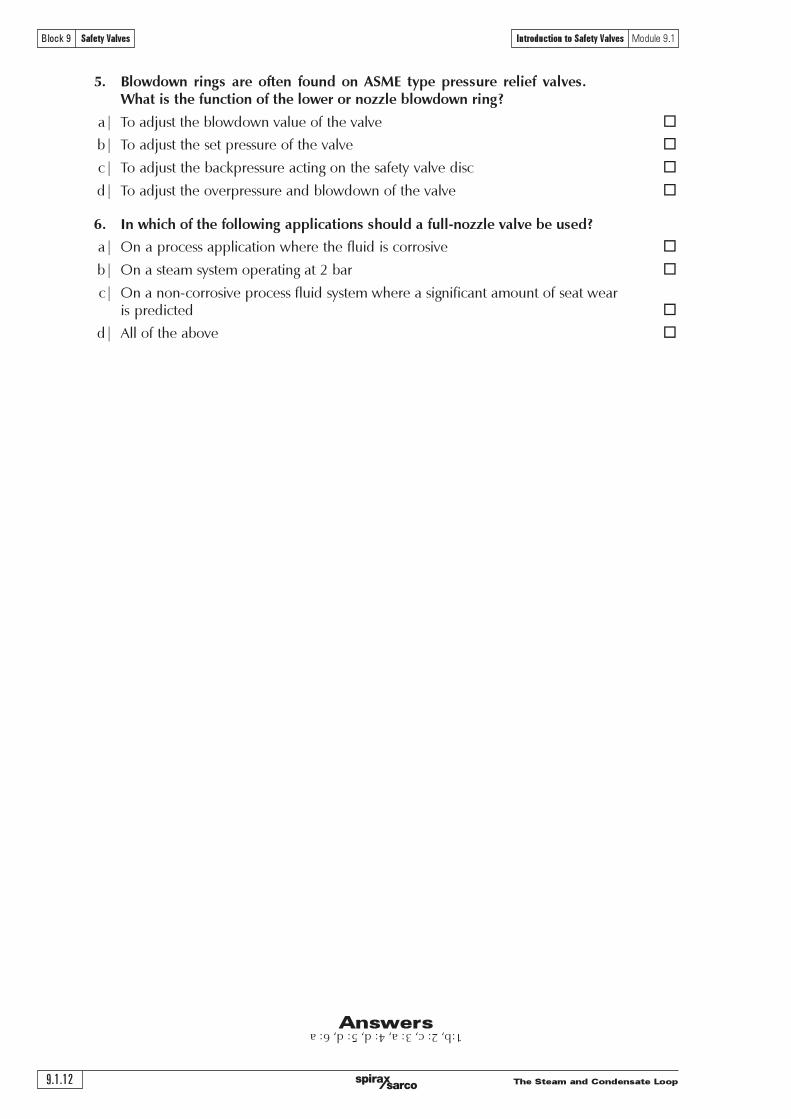
5. Blowdown rings are often found on ASME type pressure relief valves.What is the function of the lower or nozzle blowdown ring?
a| To adjust the blowdown value of the valve ¨
b| To adjust the set pressure of the valve ¨
c| To adjust the backpressure acting on the safety valve disc ¨
d| To adjust the overpressure and blowdown of the valve ¨
6. In which of the following applications should a full-nozzle valve be used?
a| On a process application where the fluid is corrosive ¨
b| On a steam system operating at 2 bar ¨
c| On a non-corrosive process fluid system where a significant amount of seat wearis predicted ¨
d| All of the above ¨
Answers 1:b, 2: c, 3: a, 4: d, 5: d, 6: a
����������������������������� �����
������� ������������� �!���"��������������� ����������
��������������������������������
������������������������� �!"#$%&'�())*�+!$#,-.+,#���/$0$'12

�����������������������������
���������������������� ����������
�����
������� �������������
����������������������
������ ���������� ��������� ������������������������ �������� �������������������������������������������������������������������������������������������������������������������������������������������������������������������
��������� ��������� �� ��������� �������������� ����������� ������������� ������� ������������� ��������������� ���°�µ�¾À�É����������������������������������������������������������������������������������������������������������������������������������������������������������������������������������������������������Ì
� ��������������������������������������������������������� ������������������������������������������������������������������������������������������������������É!������������������������������"!��������������������������������������������������������������������� ��������#�����$�%������
� ����� ������������������������������������������������������ ���������������������������������������������� ������� ����� ���� ��������� ������� ������������������������ ������������ &'!������������������������������(!������������������ ��������#�����$)�%�������
� !"#� �$%&� '�%�&(������� ������������������������� �������������������� ���������������������� ���������
� )*����$%&�'�%�&(��������������������������������������������������������������������������
� )*���+",��'�%�&(���������������������������������������������������������������������������������������������*������������������������������������������������������������������������������������������������������������
� -".��.&$".���'�%�&(�,��$�%�����������������������������������������������������������������������������������������������������������������������������������������+����������������������
� /���.0�1� '�%�&(� ,��$�%� ������ ������������� ������ ������������� �������� �������������� ����������������+���������������������������������������������������������
� 2$�"&�"3�,�&�1�3,�''*,��,��$�%���������������,�����������������������������������������������������������������-�����������*������������������������������
� 2"#�,��0&*�&�1� '�%�&(� ,��$�%� ������ ������������� ������� ������ ��������� ������,��� ������������������������������������������������������������������������� �����������*�����������������������
�������������������������������������������������������.� �Éɾ'�������������������������������������������������/��������������������������������Ì
� �&�.1�,1�'�%�&(��������������������������������������������������������������������������������������������������������������������������������������������������������������&'!��0����������������������������������������������������������������+�����������������1�
� )*��� �$%&� 4 "��5*+6�'�%�&(������� ���������������������������������������������� ����������������������������À!�������������������������������������������������������������������������������������������������������0������������������1������������������������¾'!�
� 7$,�0&��"�1�1�'�%�&(���������������������������������������������������������������������������������������������������������������������������������������
� 2,"3",&$".���'�%�&(��������������������������������������������������������������������������������������������������������������������������&'!����������������������������������������������������������������������������������������������������������&'!�����������������������������������������������������������������������������������

����������������������������� �����
������� ������������� �!���"��������������� ����������
� ���������������������������������������������������������������������������������������������������������������������������������������������������������������������������
� ���!"�� ������� ������ ����������� ������� ������� �������������� ������������ ������������� �����!��������������������������������������������������������������������������������������������"���������������������������������������������������������������������������#���������
� #!$��!���%����������������$����������������������������������������������%������������������������������������������������������������������������������&����������������������������������&������������������������������������������������
"���'�������(��������'(�)*+,������������������������������������������-
� ����&���!�%�%�������������������������������������������������������������������������������������������������������������������������������������������������������&�������������������&������������
� #!$��$��!$��� ������� ������ ���� ������� ������ ��� ����������� ������� ����&� ���� ���� ��������� �����������������������������������������������������������#���������
� '������%��������������������������������������������������&������������������������������������������&�������������������������������������������������������������������&��������������������������������������������������������&��������������������������������.���������������������������
� (��!��!������%�)�$%���&���!�%�%*����������������"����������������������������������������������������������������������������������&����������������������������������������������
� ���$&�%�+���!"�����������������������������������������������������������������������������.�����������������������������&�������������������������������#����������������������������������������&��������������������������������������������������������������������������������
� ���$&�%�+���!"���������������"�����,-�����������!$����������������������������������������������/�������������&���������������������������.���������������������&��������������������������������������������������������
� ���$&�%�����!$������������������������ ������������������������������������������.���� ������������������������&�������������������������������#������������������������������������������
� ���!"�����������������������������������������������������&����������������������������������������������������������������
%����������&�����'(�*+,������������������������������������������������������������������&�����������������&���������������������������������-
� .�����������������)!�%�$����&����*���"������������������������������������������������������������ !"#����������������������������������&���������������������������/��������012��������������������
� /������������������������3���������������������������������������������������������� "#���������������������������������&���������������������������/��������012���������������������
� 0,��� ����� ������� ������ ��3������������ ������ �������������� ��� ����� ������������ ������������0112�����412��������������������&�������������������������/��������+2���������������������
�����������������������������
���������������������� ����������
�����
������� �������������
���������������������������������������������������������������������
�!������������������������� �!����������"����
�! �!
������������������������������������������������������������������������������������������������������������������
#�������������������������"������������$�����
�������� ��$�� %���"����$�� &�������
����� ������������������������� ���
'�(��)��*������'� ���!��"�# ������������������������� ���
$�%��� ��� &��
� ����� �� ����
!"#����� !� "�
$��� #$%&'%&(�) !� "�
*$+,$- !�&%&''()*+'(,(-'.*/0
123+(4 ����� ���.-�%-& !�&/,00&0$/�&1� !�
5!(6789 123+(: #$%&'%&(�) !� !�
123+(, *$+,$- !&2&�1� �31&�&�!�
)*+'&;
4< #�45&60'7-'7.&8�0,�)&)9'7.&�%�&/'%&8�08�)&7$�9&�-:,)��60�&60'7-'7.3
:< ;�&�"1<&60'7-'7.&8�0,�)&)9'7.&�%�&/'%&8�08�)&7$�9&.'.��-:,)��60�&60'7-'7.3
,< �1�&$)&'/��.&,)�-&/'%&.'.�=�%�$/$�-&)$>$.(&=�0=,0��$'.)&�.-&�!�&=�.&6�&,)�-&/'%&/$%�&?%'��=�$'.&'/&)�'%�(�&8�))�0)3
��������������������������
������������������������������������������������������������������������������������������������������������������������������������������������������������������������������������������������������������������������������������������������������������������������������������������������������������������������������������������������������������������
� �������������������������� ������ ���������������� ������ �������� ����������� ����������������������
� ��!"����������������� ������ ����������� ��������� ���������� ��� ���� ������� ���������� ������������������������
!����"�������� ������������������ ������������������� ���� ����������������������������������������� �������� ��������������� ���� ���� ������� ���� ���� ��������� ������������� ����� ������ ���������������������������������������������
����#!$%&#'!�����������������������������������������������������������������������������������������������������������������������������������������������������������������������������������������������������������������������������������������������������������������������������������������������������(������)�*�+������������������������������������������������������������������������������������������������������������������������������������
����������
!"�#��$%##�&
=�
=�
=�
=�����
=�
���'�("�(�) *
=�=�
=�����
+�#&���!"�#��$%##�&
!"�#�>!
+�#&
="="
,%--.�("�(�) #*
!"�#�>!
,%--.�("�(�) #*
���'�("�(�) *
����������������������������� �����
������� ������������� �!���"��������������� ����������
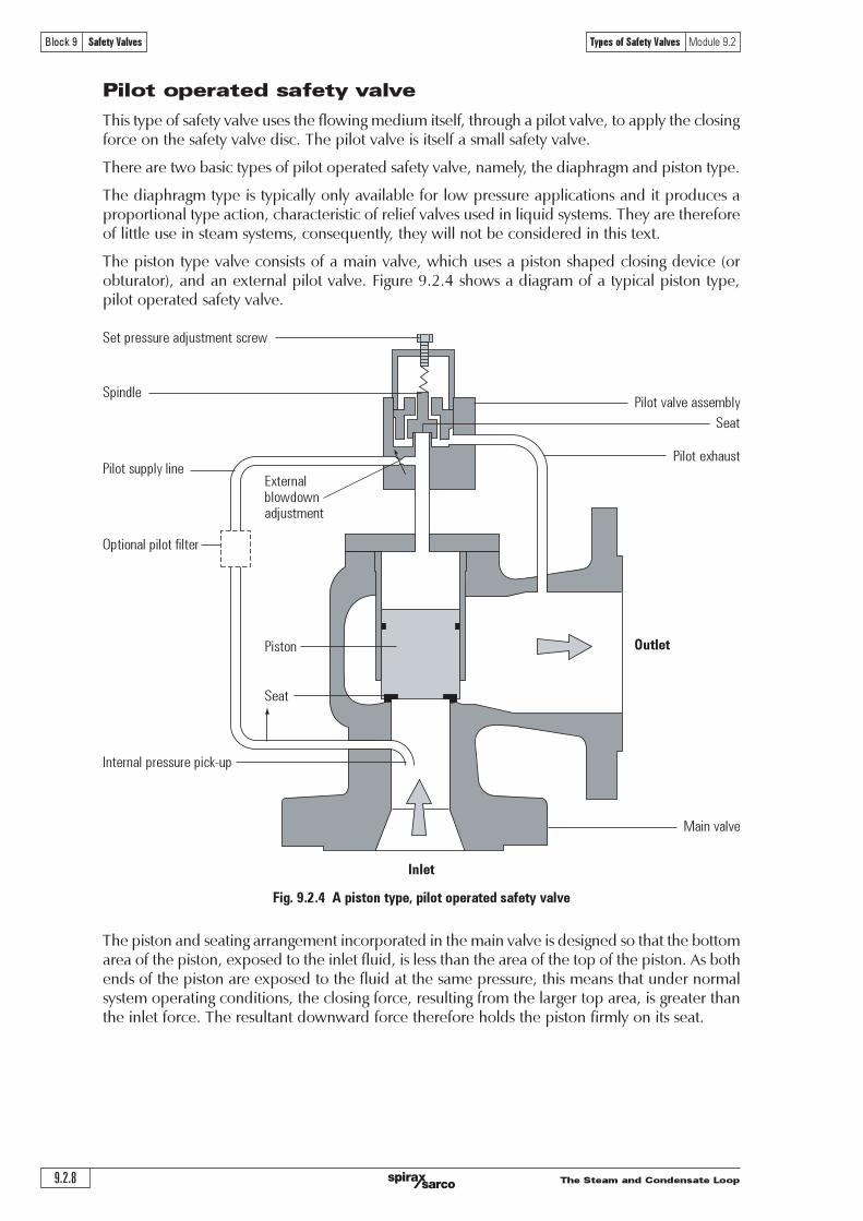
��������������� ���� ����������������� ��������� ������������� !� �������"������� ����� ������#$�����%��������������#$�&�'�����������%���$��������'���%����$����( �����������))'���������! ��������$*���������%������������+" ����������������$���������"��,%����$����(# �����������������%����"����*������������-�.�����������������%�������$�����&�����������������������������������&�'&������/01����&�������'����������'����&�'&�!�����+��$���2-3-4��� !�������#$������%��������������5
��������������
6����5( 7 +'$�����'���%����$���! 7 8�))'������+" 7 /%����������(# 7 ���,%����$��
9��������!������$%���*%�����"��,%����$�����''�����������������������'����������������������'��%����$�����#$��������'�����������������������-
.����������������&�'&���������%�������$����� ���&���������������*��%������+��$���2-3-4" !� �����#$������%��������������5
��������������
6����5( 7 +'$�����'���%����$���! 7 8�))'������+" 7 /%����������(# 7 ���,%����$���� 7 :��������
9�$�!������$%���*%�����"��,%����$�����������������&����'�%����$�������&����*�������%����������!���������%������%����$�����''�"��'����������;%�����-
.��"���������!�������������������$%���*%�����"��,%����$����;����!������������������������%����$����������"�������������������������������������&�'&�������*-
<��������&�'&�������������%��!����������������"$�'�=$%�"��,%����$����'�����&�����"����,�����������$��-�+��������&�������'��������&�'&������������%�������$�����&����������������������������������&�'&�!�����+��$���2-3-4��� !���������������"$�'�=$%�"��,%����$�������"�������*�����"�������������1#$������2-3-4�����"�����������������������&�'&�������������%��!�������'���%����$�����������$*�����������%����$��!�("!����������&��%����$��!�($-
�������������
6����5(" 7 /���%����$�������������&�'&���! 7 8�))'������+" 7 /%����������(# 7 ���,%����$��($ 7 <&��%����$��
9��������!� ��� ����"��,%����$��� ��� �������� ����� �����&��%����$��!� ���� &�'&����''� ����� ��� �'���!���$����������'��-�9��������'������������"�'��������������������*������������$'������'$����������������������&�'&�-

�����������������������������
���������������������� ����������
�����
������� �������������
��������������������������������������������������������������������
����������������������������������������������������������������������������������������������������������� ������ ��!�����"��#
������������������
�����������
�
�
�
�
��!
�
�!
������
"���
!"#"�!$
!"
$����������� ����������������������������������"���������������������%����������� �������&������� "���'"�� ��!�����"���������%��������������(�����&������)�*����������������*+$�,-.�/���((�����+��������0"��������#
� *�������������������"�������������������"����������������� ��"����%�������� "���'"�� ��!�����"������������������1.2�����������������"������1.2����������"��)�*��������(�&�("(�����%� �� "���'"�� ��!�����"���(��� ��"�����������������"����������������1.2)
3�����������4���������4�56,7����%���������������������� "���'"�� ��!�����"������"��� ����(�������1-2�����������������"���%������������������������������������������������������)
8�������(�9�������������(������������������� ��!�����"������� ��(����������%��������������(��� �������"������:�����������������������)�3����%���� ������"��������;��"���7)<)�$�����%�������������������� ���������"������� ��!�����"������������(��� ���������������"����� ��������������������)
����������������������
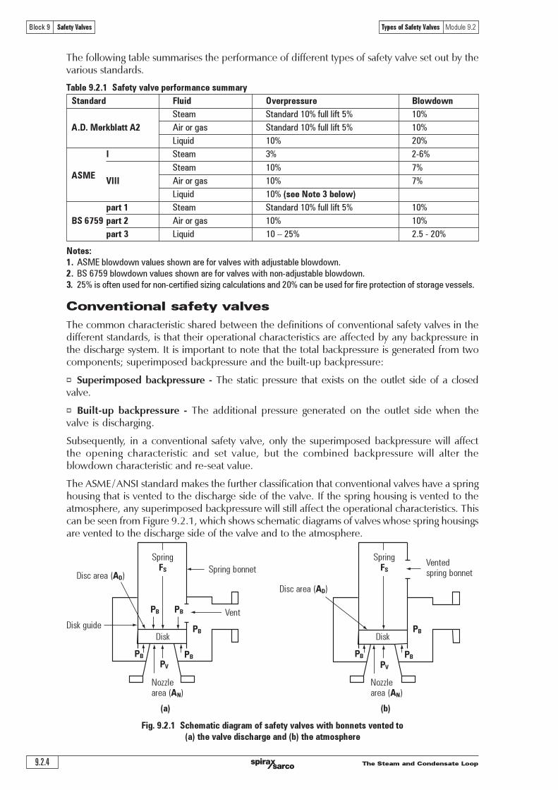
����������������������������������������������������(�����������(����������������������� ��!�����"��)3����������%�� ���������������������� ��"�������������������#
� ������� �������������� ������� ������*����"�������������������������������������������������������������������������������������������������%�����(���(������������������� ������������"���)�3��������������������������������������*�������������::��������������* ������������������ ���="��)�3����(������������������������������� ���������������� ����(��"��������������������&������������� ��!�����"��������="������������������������������������������� �������)�$����������������������� �����������������"��������������������������������������" 9�����������(��������������"����������%�����8��"���7)-)-)
>����#+! ? 8�"��������������"��* ? @�::�������8" ? 4�����������+# ? ���!�����"��*$ ? A��������*� ? +����������
4�����*���="����* ������������%�����(����������="�����������="������(�����"���������������"���������="�����)�3�����������������(�����������B="������7)-)<)
!$
!%
����������������������������� �����
������� ������������� �!���"��������������� ����������
������������������������������������������������������������������
������������������
������������
�
��!
! !"�!"
����"����#�"�
�������
�#
��������������
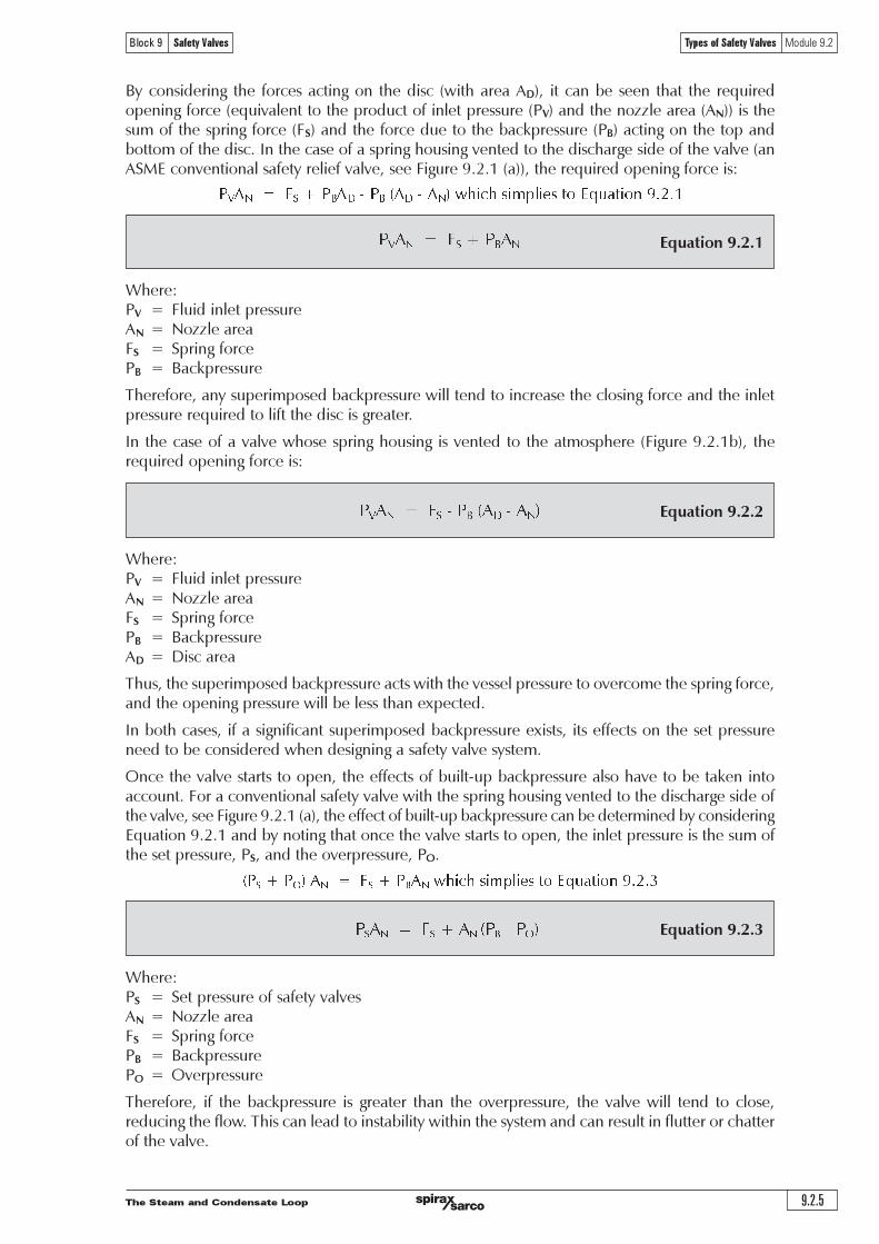
������ � ! "#$%&'%(#�)'*��++$��, ! -.//#�'0��0"! ! 1*�%(2'3.�4�
� !""�#$� �%&!�'�"��(!)� $�*!�%� +�"+!�,'5�##.6+'6%)�'0('�33�4)%7�'0��0'8,"9'�:$%70#�()').')��'(.//#�'+�0)'0��0'8, 9'%+'0))04��&').')��$**��'+$�304�'.3')��'&%+4'0(&').')��'+*%(&#�'2$%&�;
<��'5�##.6+'0��0(2�=�()'*��7�()+'504>*��++$��'04)%(2'.(')��'$**��'+%&�'.3')��'&%+4'6%)�%()��'0��0'.3')��'5�##.6+;'<��'&%+4'0��0'�?)�(&%(2'5�@.(&')��'5�##.6+'0(&')��'.**.+%(2'&%+40��0'0��'�:$0#A'0(&'+.')��'3.�4�+'04)%(2'.(')��'&%+4'0��'50#0(4�&A'0(&')��'504>*��++$��'�0+#%))#�'�33�4)'.(')��'70#7�'.*�(%(2'*��++$��;
<��'5�##.6+'7�()'0##.6+'0%�').'3#.6'3���#@'%('0(&'.$)'.3')��'5�##.6+'0+')��@'�?*0(&'.�'4.()�04);B�##.6+'30%#$��'%+'0('%=*.�)0()'4.(4��('6��('$+%(2'0'5�##.6+'50#0(4�&'+03�)@'70#7�A'0+')�%+=0@'033�4)')��'+�)'*��++$��'0(&'40*04%)@'.3')��'70#7�;'C)'%+'%=*.�)0()A')����3.��A')�0)')����'%++.=�'=�4�0(%+='3.�'&�)�4)%(2'0(@'$(4�0�04)��%+)%4'3#$%&'3#.6')��.$2�')��'5�##.6+'7�()+;'C(0&&%)%.(A' +.=�'5�##.6+' 50#0(4�&' +03�)@' 70#7�+' %(4#$&�' 0(' 0$?%#%0�@' *%+).(' )�0)' %+' $+�&' )..7��4.=�')��'�33�4)+'.3'504>*��++$��'%(')��'40+�'.3'5�##.6+'30%#$��;'<�%+')@*�'.3'+03�)@'70#7�'%+$+$0##@'.(#@'$+�&'.('4�%)%40#'0**#%40)%.(+'%(')��'.%#'0(&'*�)�.4��=%40#'%(&$+)�%�+;
C('0&&%)%.(').'��&$4%(2')��'�33�4)+'.3'504>*��++$��A')��'5�##.6+'0#+.'+��7�').'%+.#0)�')��'+*%(&#�2$%&�'0(&')��'+*�%(2'3�.=')��'*�.4�++'3#$%&A')�%+'%+'%=*.�)0()'6��(')��'3#$%&'%+'4.��.+%7�;
1%(4�' 50#0(4�&'*��++$��' ��#%�3' 70#7�+' 0��' )@*%40##@'=.��' �?*�(+%7�' )�0(' )��%�' $(50#0(4�&4.$()��*0�)+A')��@'0��'4.==.(#@'.(#@'$+�&'6����'�%2�'*��++$��'=0(%3.#&+'0��'$(07.%&05#�A.�'%('4�%)%40#'0**#%40)%.(+'6����'0'7��@'*��4%+�'+�)'*��++$��'.�'5#.6&.6('%+'��:$%��&;
!"
! !
�����������������������������
���������������������� ����������
�����
������� �������������
���������������������������
������������������������������������������������������������������������������������������������������������������������������������������������������������������������������������
������������������������������������������������������������������������������������������������
�����������������������������������������������������������������������������������������������������������������������������������������������������������������������������������������������������������������������������������������������������������������������������������������
������������������������������������������������������������������������������������������������������������������������������������������������������������������������������������������������������������������������
������������������������������������������������������
�����������������������������
�� ��!�
" !#������!$�! ��
%�� #��!�� !#��& !���
'(�����!)!#��#������������
����
" !#���(*����
!����
+� ��,�!,�
"����
-������!����������� �./��
" ��#�
����
������������������������������������������������������������������������������������������������������������������������������������������������������������������������������������������������ ���������������������������������������������������������������������������������������������������������������������������������������������������������������������������������������������������������������������������������������������������������������������������������������������������
" !#��,�!,�������)!$

����������������������������� �����
������� ������������� �!���"��������������� ����������
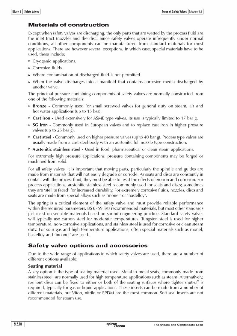
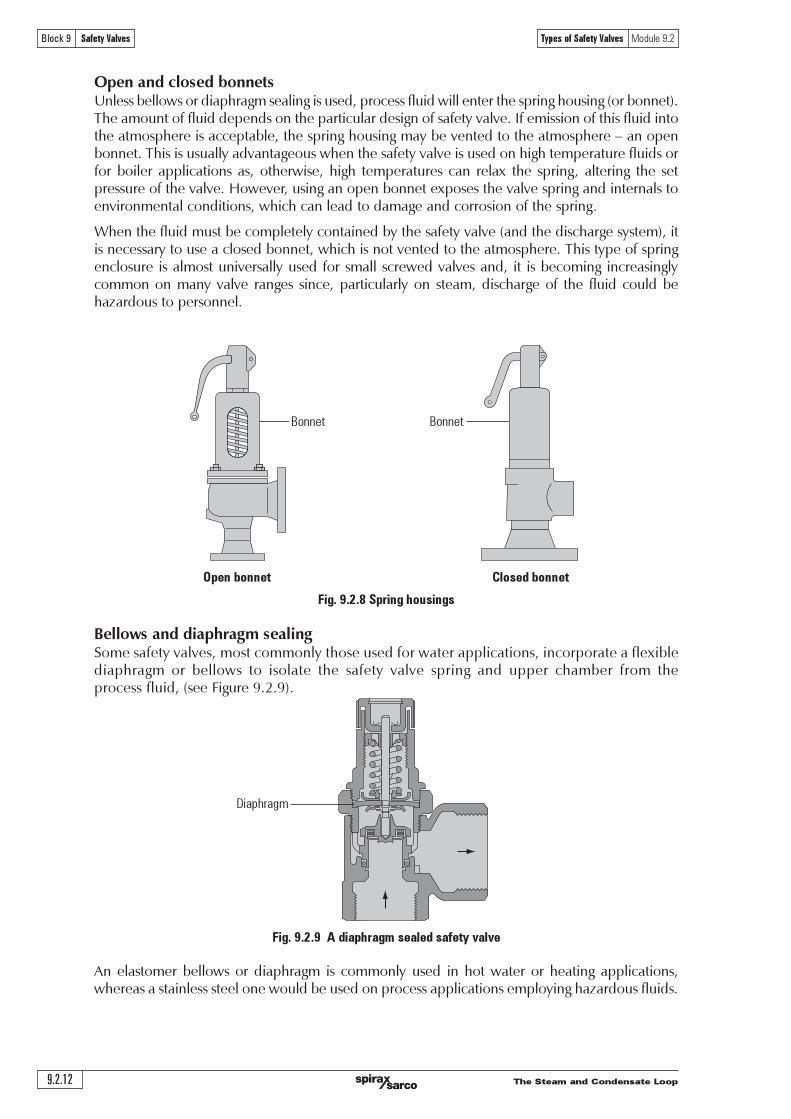
������������������������������������������������������������������������������������������������������� ������ ���� ���� ��� ����������!�"��������#$�%���&��������� ���� ������ ��������� �������� ���� �����������������������&��&�����������������������������������#�����������'�&������������$�(����"������������#��������������������������������������������������������������������������������������������#����������#��������������������&����������$�)���������������"����&��&���������������������������������������#����'��#��������#$
(���������������������������'���������������!���#���#������������&��&�������������������&����������������������������� ����#� ���"������������ ������������ �����'!��� ����'�������� ��������#������#���������#�����������������������������$
*������������#������!�&��&������������#��&�������������#�'���#����������"�����+��'���#������,-�����������'��.$�/�������������������!��������#����������������"�����������0����#�'�������������������������#������!���"�������������������$�*������������#�&��&�������������&����'�����"�������������1����"�2�������"�������������#��!�����������!�&��&�����������������������$
3����������"�������������������������������#������!�&��&����������������"����'���������������������������������������'������'���2����'!���������"����������#���������������������������#��������������������$�)���� ���� ���#� ��� ���� ����������� ���� &��&��� ������� ��� ������������ �����#����������#����#�����������������'���2����������$
)���4�������5���#��#�45�6789������������������������������#������!�&��&��������#���&����������������#����#����������#�&������������������������#���#�&�#����!���#��������#�������������������������������������������������������'������������!�&��&��������������������������������&��!$
�����������������������������������������������
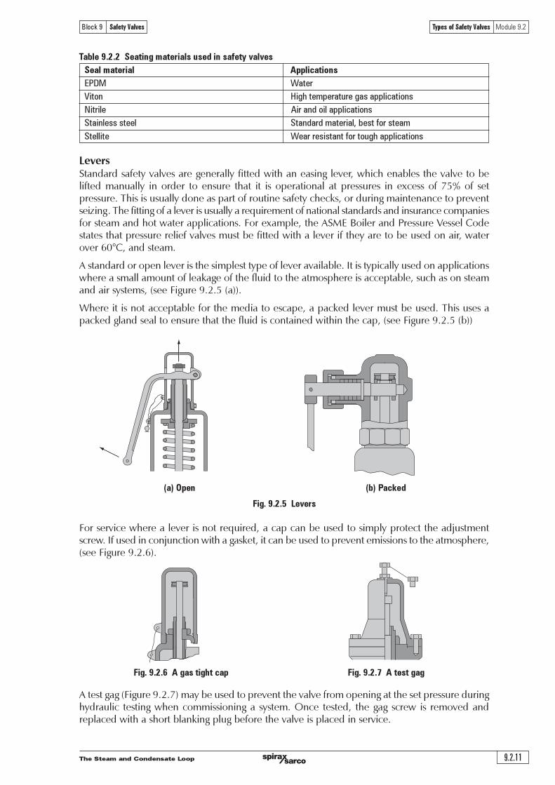
)������"�������������������������#������������������������"�����������&�������#������#�������������"�&�����"����������#����������������������������0����#�������#����������������#�#����������������!����#���������������������#����������������!��������&��&�$
:����������������!�&��&����������������������#���������������������!���������������������������������������������������#�������������$�)���#�����������������#����������������������!��������&��&�������'��0�����!�#����"���#�'!�����'��������$�)��������������������#������������#���������������������0���������� ����'����#��"����$�:� ����� ��������&��������� �����!�&��&�� ��������� ����'����������� ���������������"�������������$
)���#������������������������!�&��&����������#����������������������� !"��������'����#��"����$�)����"�����������������������������#�����"����!���������������������#�����#����"���������#�������������$)���#���������������������������������&��&������#����'��������������!������������������������������&��&������#���������&���#����������������!��������������!������'�������������������������&��&��������������"�������1����&�������"����"����������������������#��������������&��&���������������!�������������#&�������$�/������"���������������&��&������#����'�����#������"������'�������#�����������������������"����������������$
������������&��&��������#�������!���������#������������� #!"��������'����#��"����$�)���#����������������#����"���#��������!�'!���������������������#�������#�����������#�������!����������"�����"�����������������������#����'��"������������������������������������������&��&��$
�����������������������������
���������������������� ����������
������
������� �������������
�������������������������
������������������������������������������������������������������������������������������������������ ������ ������ ��������� ���� ���� ������ ������ ������� ������� �������� ������������� ������ ������������������ ���� ������ ����������� ���� ���������������� ����� ������������������� ���������������������������������������������������������������������������������������������������������������������������
� ����������������������
� ��������� �������
� !��������������������������������������������������������
� !���� ���� ������ ����������� ����� ����������� ����� ��������� ���������������� ����������� ����������������
����������������������"���������������������������������������������������������������������������������������������������
� ������� �� �������� ����� ���� ������ �������� ������� ���� �������� ����� ��� ������� ���� ���������������������������������#$������
� !"#�$������%��������������������&�'���������������(�������������������������������#)�������
� %&� $���� �� ������������� ����������������������� ��� ������������� ����� ��������������������������������*$��������
� !"#�"#��'��� ����������������������������������������������+,���������-�����������������������������������������������������������������������������������������������������������
� ()"#��$#$*�"#!$�'�""�"#��'���%��������������������������������������������������������
.������������������������������������������������������������������������������� �����������������������������
.���������������������� ��� ��� ���������������������������������������������������������������������������������������������������������������������������������&�������������������������������������������������������������������������������������������������������������������������������������.���������������������������������������������������������������������������������������/�������������������0��������������1���������������������������.��������������������������������������������������������������������������������������������0�����1����0���������1�
���� ������� ��� �� ��������� ����������� ���� ������� ������ ����������������� ����������������������������������������������������2��3)$4������������������������������������������������������5������������������������������������������������������������������������������������������������� ��������������������������� ������������� ����������������������������� �������� ��������������������������"��������������������������������������������������������������������������������������.���������������������������������������������������������������������������������������������������0�������1����������
����!�"��"���#��������$������������
6�����������������������������������������������������������������������������������������������������������������������
����������������&�7������������������������������������������������'����"��"�������������������������������������������������������������������������������������������������������������������&����������������������������� ������� ������ ��������������������� ���� �������� ��������������� �������� ����"���� �������������������������������������������������������������������������������������������������������������������������8������������������-6'�������������������������������������������������������������������������
����������������������������� ������
������� ������������� �!���"��������������� ����������
������������������
����������������������������������������������������������������������������������������������������������������������������������������������������������������������������������������������������������������� �
��������� ��!��"��#��$#�%"& ���������'��!�#��#��"�
���������������������������������������������������������������������������������������������������������� � ��������!���� �����������������������"� �� ������#� ��������� ��!� ��� ���������������� ���!����������������$�������������������������������� ����������� ��
����������������������������������������������������
������������� ������������
���� �����
!�"# $!%&'��()����*��'%�+'�)),!-��!"#+
.!��!,� /!�'�#0'"!,'�)),!-��!"#+
1��!#,�++'+���, 1��#0��0'(����!�,2'3�+�'4"�'+���(
1��,,!�� ����'��+!+��#�'4"�'�"*%&'�)),!-��!"#+
������
%�������������������������������������������!�������������������#�!�� ����������������������������������������� ��������� ��� ������� ����� ��� ��� ������������ ������������� ��� �& ������� �'(���� �������������)���������������������������������������������� �� $�#�������������������� ���������������*�����)�������������������������������������+������������������������������������������ �� ��������������������������!���������� �������������&�����#������%,-�.����������/��������0������1�����������������������������������������������������!�����������������������������������������#�!���������23�1#�����������
������������������������������������������������������������������4��������� ������������������ ������!��������������������������$��������������������������������������� �������#��� ����������������������������#�����������������'������
5���������������� ��������������������������� ���#����� $�����������������������)������������ $������������������������������������������ ���������!���������� ��#�����������������'�����
�!�"��#�� �!�$���
�����������������������������
���������������������� ����������
������
������� �������������
���������������������������������������������������������������������������������������������������������������������������������������������������������������������������������������������������������������������������������������������������������������������������������������������������������������������������������������������������������������������������������������������������������������������������������������������������������������������� ������������� ���� ������ ���� ����������������� ���� ��������������������������������������������������������������������������������������������������������������������������������������������������������������������������������
���������������������������������������������������������������������������������������������������������������������������������������������������������������������������������������������������������������������������������������������������������������� ��� ��������������������������������������������� ������� ����������������������� �������������������� ���� ���������������� ��������������������
��������������������������
��������������������������������� ��� �������������� ��������������������������������������������������������������������������������������������������������������������� ��������������
������������ �!�"���"�#��$"%$!��"&$'(�)"%)$
����!�������"��#$�%&�����"�%!���������������������������������������������������������������������������������������������������� ��� �������� ��� �������� ���� ������� ������ ������� ���� ������ �������� ����� �����������������������"������#�$�#��
*%��$!�+���$',�$��+���$'
���������
!""#$ !""#$
����������������������������� ������
������� ������������� �!���"��������������� ����������
�������
!��"#$��
�� �������������������������������������������������������������������������������������������������������������������������������������������
�� �� �
� !"� �
#� !�� �
$� %"� �
� !������������"��#�����������������$��������������������������������������������������
�� &'()$()* �
� +,-#.�/012 #�3�#,45 �
#� 61427�'81 �
$� 9''2(:24.12� (71 �
%� �����������������������������������������������������"��������������������������������"�������������������������"��$��������������������������������
�� ;8''2',:4 �
� <,0.2',:4 �
#� =()2',:4 �
$� ;8''2 (/1 �
&� ������������������$����������������"������������������������������������������
�� !���������������������������������"��$��$�������������"��
��� '���������������������������������������������������������������������������������(���
���� )������������������������������������������������������������������������"��������������������������������������������������
�� ,2(*'5 �
� ,,,2(*'5 �
#� ,2�*$2,, �
$� ,>2,,2�*$2,,, �
*� ���������������$�����"������������"������������������������������������������������������������������� *�"���
�� 98-41*,4,#2-4�,*'1--2-411' �
� 6?2,/(* �
#� @�-42#�/ (*2-411' �
$� &/(*A1 �
+� ������������������$����"�������������������$�����"����,�����������������$����������������������������������������������������
�� B31*2 (**142�*$23�#C1$2'171/ �
� @'(-1$2 (**142�*$2(31*2'171/ �
#� @'(-1$2 (**142�*$23�#C1$2'171/ �
$� ?�-24,0.42#�3 �
���������������������������������
�����������������������������
���������������������� ����������
������
������� �������������

The Steam and Condensate Loop 9.3.1
Block 9 Safety Valves Safety Valve Selection Module 9.3
Module 9.3Safety Valve Selection
SC
-GC
M-7
0
CM
Iss
ue 3
©
Cop
yri
ght
20
07
Sp
irax-
Sarc
o L
imit
ed
The Steam and Condensate Loop
Safety Valve Selection Module 9.3
9.3.2
Block 9 Safety Valves
Safety Valve Selection
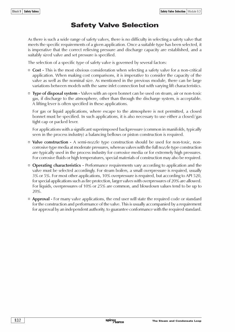
As there is such a wide range of safety valves, there is no difficulty in selecting a safety valve thatmeets the specific requirements of a given application. Once a suitable type has been selected, itis imperative that the correct relieving pressure and discharge capacity are established, and asuitably sized valve and set pressure is specified.
The selection of a specific type of safety valve is governed by several factors:
o Cost - This is the most obvious consideration when selecting a safety valve for a non-criticalapplication. When making cost comparisons, it is imperative to consider the capacity of thevalve as well as the nominal size. As mentioned in the previous module, there can be largevariations between models with the same inlet connection but with varying lift characteristics.
o Type of disposal system - Valves with an open bonnet can be used on steam, air or non-toxicgas, if discharge to the atmosphere, other than through the discharge system, is acceptable.A lifting lever is often specified in these applications.
For gas or liquid applications, where escape to the atmosphere is not permitted, a closedbonnet must be specified. In such applications, it is also necessary to use either a closed/ gastight cap or packed lever.
For applications with a significant superimposed backpressure (common in manifolds, typicallyseen in the process industry) a balancing bellows or piston construction is required.
o Valve construction - A semi-nozzle type construction should be used for non-toxic, non-corrosive type media at moderate pressures, whereas valves with the full nozzle type constructionare typically used in the process industry for corrosive media or for extremely high pressures.For corrosive fluids or high temperatures, special materials of construction may also be required.
o Operating characteristics - Performance requirements vary according to application and thevalve must be selected accordingly. For steam boilers, a small overpressure is required, usually3% or 5%. For most other applications, 10% overpressure is required, but according to API 520,for special applications such as fire protection, larger valves with overpressures of 20% are allowed.For liquids, overpressures of 10% or 25% are common, and blowdown values tend to be up to20%.
o Approval - For many valve applications, the end user will state the required code or standardfor the construction and performance of the valve. This is usually accompanied by a requirementfor approval by an independent authority, to guarantee conformance with the required standard.

The Steam and Condensate Loop 9.3.3
Block 9 Safety Valves Safety Valve Selection Module 9.3
Setting and sealing
In order to establish the set pressure correctly, the following terms require careful consideration:
o Normal working pressure (NWP) - The operating pressure of the system under full-loadconditions.
o Maximum allowable working pressure (MAWP) - Sometimes called the safe working pressure(SWP) or design pressure of the system. This is the maximum pressure existing at normaloperating conditions (relative to the maximum operating temperature) of the system.
o Maximum allowable accumulation pressure (MAAP) - The maximum pressure the system isallowed to reach in accordance with the specification of the design standards of the system.The MAAP is often expressed as a percentage of the MAWP.
For steam using apparatus, the MAAP will often be 10% higher than the MAWP, but this is notalways the case. If the MAWP is not readily available, the authority responsible for insuring theapparatus should be contacted. If the MAAP cannot be established, it must not be consideredto be higher than the MAWP.
o Set Pressure (PS) - The pressure at which the safety valve starts to lift.
o Relieving pressure (PR) - This is the pressure at which the full capacity of the safety valve isachieved. It is the sum of the set pressure (Ps) and the overpressure (Po).
o Overpressure (PO) - The overpressure is the percentage of the set pressure at which the safetyvalve is designed to operate.
There are two fundamental constraints, which must be taken into account when establishing asafety valve set pressure:
1. The set pressure must be low enough to ensure that the relieving pressure never exceeds themaximum allowable accumulation pressure (MAAP) of the system.
2. The set pressure must be high enough to ensure that there is sufficient margin above thenormal working pressure (NWP) to allow the safety valve to close. However, the set pressuremust never be greater than the maximum allowable working pressure (MAWP).
In order to meet the first constraint, it is necessary to consider the relative magnitudes of thepercentage overpressure and the percentage MAAP (expressed as a percentage of the MAWP).There are two possible cases:
o The percentage overpressure of the safety valve is less than or equal to the percentageMAAP of the system - This means that the set pressure can be made to equal the MAWP, asthe relieving pressure will always be less than the actual MAAP.
For example, if the safety valve overpressure was 5%, and the MAAP was 10% of the MAWP,the set pressure would be chosen to equal the MAWP. In this case, the relieving pressure(equal to the set pressure + 5% overpressure) would be less than the MAAP, which is acceptable.
Note that if the percentage MAAP were higher than the percentage overpressure, the set pressurewill still be made to equal the MAWP, as increasing it above the MAWP would violate thesecond constraint.
o The percentage overpressure of the safety valve is greater than the percentage MAAP ofthe system - In this case, making the set pressure equal to the MAWP will mean that therelieving pressure would be greater than the MAAP, so the set pressure must be lower than theMAWP.
For example, if the safety valve overpressure was 25% and the percentage MAAP wasonly 10%, making the set pressure equal to the MAWP means that the relieving pressurewould be 15% greater than the MAAP. In this instance, the correct set pressure should be 15%below the MAWP.
The Steam and Condensate Loop
Safety Valve Selection Module 9.3
9.3.4
Block 9 Safety Valves
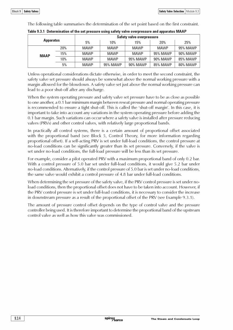
The following table summarises the determination of the set point based on the first constraint.
Table 9.3.1 Determination of the set pressure using safety valve overpressure and apparatus MAAP
Safety valve overpressureApparatus
5% 10% 15% 20% 25%
20% MAWP MAWP MAWP MAWP 95% MAWP
MAAP15% MAWP MAWP MAWP 95% MAWP 90% MAWP
10% MAWP MAWP 95% MAWP 90% MAWP 85% MAWP
5% MAWP 95% MAWP 90% MAWP 85% MAWP 80% MAWP
Unless operational considerations dictate otherwise, in order to meet the second constraint, thesafety valve set pressure should always be somewhat above the normal working pressure with amargin allowed for the blowdown. A safety valve set just above the normal working pressure canlead to a poor shut-off after any discharge.
When the system operating pressure and safety valve set pressure have to be as close as possibleto one another, a 0.1 bar minimum margin between reseat pressure and normal operating pressureis recommended to ensure a tight shut-off. This is called the �shut-off margin�. In this case, it isimportant to take into account any variations in the system operating pressure before adding the0.1 bar margin. Such variations can occur where a safety valve is installed after pressure reducingvalves (PRVs) and other control valves, with relatively large proportional bands.
In practically all control systems, there is a certain amount of proportional offset associatedwith the proportional band (see Block 5, Control Theory, for more information regardingproportional offset). If a self-acting PRV is set under full-load conditions, the control pressure atno-load conditions can be significantly greater than its set pressure. Conversely, if the valve isset under no-load conditions, the full-load pressure will be less than its set pressure.
For example, consider a pilot operated PRV with a maximum proportional band of only 0.2 bar.With a control pressure of 5.0 bar set under full-load conditions, it would give 5.2 bar underno-load conditions. Alternatively, if the control pressure of 5.0 bar is set under no-load conditions,the same valve would exhibit a control pressure of 4.8 bar under full-load conditions.
When determining the set pressure of the safety valve, if the PRV control pressure is set under no-load conditions, then the proportional offset does not have to be taken into account. However, ifthe PRV control pressure is set under full-load conditions, it is necessary to consider the increasein downstream pressure as a result of the proportional offset of the PRV (see Example 9.3.1).
The amount of pressure control offset depends on the type of control valve and the pressurecontroller being used. It is therefore important to determine the proportional band of the upstreamcontrol valve as well as how this valve was commissioned.

The Steam and Condensate Loop 9.3.5
Block 9 Safety Valves Safety Valve Selection Module 9.3
Equation 9.3.1 !"#$%$&'"#$($ )#
Example 9.3.1A safety valve, which is to be installed after a PRV, is required to be set as close as possible tothe PRV working pressure. Given the parameters below, determine the most suitable safetyvalve set pressure:
PRV set pressure: 6.0 bar (set under full-load conditions)PRV proportional band: 0.3 bar operating above the PRV working pressureSafety valve blowdown: 10%
Answer:Since it is necessary to ensure that the safety valve set pressure is as close to the PRV workingpressure as possible, the safety valve is chosen so that its blowdown pressure is greater thanthe PRV working pressure (taking into account the proportional offset), and a 0.1 bar shut-offmargin.
Firstly, the effect of the proportional offset needs to be considered; the normal maximum workingpressure that will be encountered is:
6.0 bar + 0.3 bar = 6.3 bar (NWP)
Where:CDSP = Cold differential set pressureRISP = Required installed set pressureCBP = Constant backpressure
For variable superimposed backpressure, the effective set pressure could change as thebackpressure varies, and a conventional valve could not be used if the variation were more than10% to 15% of the set pressure. Instead, a balanced valve would have to be used.
The pressure level relationships for pressure relief valves as shown in the API RecommendedPractice 520 is illustrated in Figure 9.3.1.
By adding the 0.1 bar shut-off margin, the blowdown pressure has to be 10% greater than6.4 bar. For this example, this means that the safety valve�s set pressure has to be:
The set pressure would therefore be chosen as 7.04 bar, provided that this does not exceedthe MAWP of the protected system.
Note that if the PRV were set at 6.0 bar under no-load conditions, and with a safety valve 10%blowdown, the safety valve set pressure would be:
Effects of backpressure on set pressure
For a conventional safety valve subject to a constant superimposed backpressure, the set pressureis effectively reduced by an amount equal to the backpressure. In order to compensate for this,the required set pressure must be increased by an amount equal to the backpressure. The colddifferential set pressure (the pressure set on the test stand) will therefore be:
=
!!
"#$%&% '# %()*
!!%+% !
( ) !!
"#$%&%!# %'% "#(%)*+
!!%,% !
=

The Steam and Condensate Loop
Safety Valve Selection Module 9.3
9.3.6
Block 9 Safety Valves
Fig. 9.3.1 Pressure level relationships for pressure relief valves (from API 520)
Pressure vessel requirements Percentagevessel pressure
%
Typical characteristics ofsafety relief valves
121
120
116
115
110
105
100
95
90
85
Maximum allowableaccumulated pressure
(fire exposure only)
Maximum allowableaccumulated pressure
for multiple valve installation(other than fire exposure)
Maximum allowableaccumulated pressure
for single valve(other than fire exposure)
Maximum allowableworking pressure or
design pressure(hydronic test at 150% NWP)
Equal maximum normaloperating pressure
Pe
rce
nt
of
ma
xim
um
all
ow
ab
le w
ork
ing
pre
ssu
re (
ga
ug
e)
Maximum relieving pressurefor fire sizing
Maximum relieving pressurefor process sizing:- Multiple valves- Single valves
Margin ofsafety dueto orificeselection
Maximum allowable setpressure for supplementalvalves (fire exposure)
Overpressure (maximum)
Maximum allowable setpressure for supplementalvalves (process)
Overpressure (typical)
Maximum allowable setpressure for single valve(average)
Start to open
Blowdown (typical)
Seat clamping force
Reseat pressure forsingle valve (typical)
Standard leaktest pressure
Set pressure tolerance ±3%
Simmer(Typical)

The Steam and Condensate Loop 9.3.7
Block 9 Safety Valves Safety Valve Selection Module 9.3
Fig. 9.3.2 Sealed cap showing a lead seal
To prevent unauthorised alteration ortampering, most standards require provision tobe made for sealing the valve after setting.
The most common method is to use sealing wireto secure the cap to the spring housing and thehousing to the body. It may also be used to lockany blowdown adjuster ring pins into position.
The wire is subsequently sealed with a lead seal,which may bear the imprint of the setter�strademark.
Setting a safety valve
For most types of safety valve, air or gas setting is permissible. A specially constructed test stand isusually employed, allowing easy and quick mounting of the safety valve, for adjustment, andsubsequent locking and sealing of the valve at the required set pressure.
The most important requirement, in addition to the usual safety considerations is that instrumentquality gauges are used and a regular calibration system is in place. All safety valve standards willspecify a particular tolerance for the set pressure (which is typically around 3%) and this must beobserved. It is also important that the environment is clean, dust free and relatively quiet.
The source of the setting fluid can vary from a compressed air cylinder to an intensifier andaccumulator vessel running off an industrial compressed air main. In the latter case, the air mustbe clean, oil, and water free.
It is worth noting that there is no requirement for any sort of capacity test. The test stand simplyenables the required set pressure to be ascertained. Usually this point is established by listeningfor an audible �hiss� as the set point is reached. When making adjustments it is imperative forboth metal seated and soft seated valves that the disc is not allowed to turn on the seat or nozzle,since this can easily cause damage and prevent a good shut-off being achieved. The stem shouldtherefore be gripped whilst the adjuster is turned.
There is a fundamental difference in the allowable setting procedures for ASME I steam boilervalves. In order to maintain the National Board approval and to apply the �V� stamp to thevalve body, these valves must be set using steam on a rig capable not only of achieving thedesired set pressure but also with sufficient capacity to demonstrate the popping point andreseat point. This must be done in accordance with an approved, and controlled, qualityprocedure. For ASME VIII valves (stamped on the body with �UV�), if the setter has a steamsetting facility, then these valves must also be set on steam. If not, then gas or air setting ispermissible. For liquid applications with ASME VIII valves, the appropriate liquid, usually water,must be used for setting purposes.
In the case of valves equipped with blowdown rings, the set positions will need to be establishedand the locking pins sealed in accordance with the relevant manufacturer�s recommendations.
Sealing
For valves not claiming any particular standard and with no reference to a standard on thename-plate or supporting literature there is no restriction on who can set the valve. Such valvesare normally used to indicate that a certain pressure has been reached, and do not act as asafety device.
For valves that are independently approved by a notified body, to a specific standard, the settingand sealing of the valve is a part of the approval. In this case, the valve must be set by themanufacturer or an approved agent of the manufacturer working in accordance with agreedquality procedures and using equipment approved by the manufacturer or the notified body.
Lead seal
The Steam and Condensate Loop
Safety Valve Selection Module 9.3
9.3.8
Block 9 Safety Valves
(b)
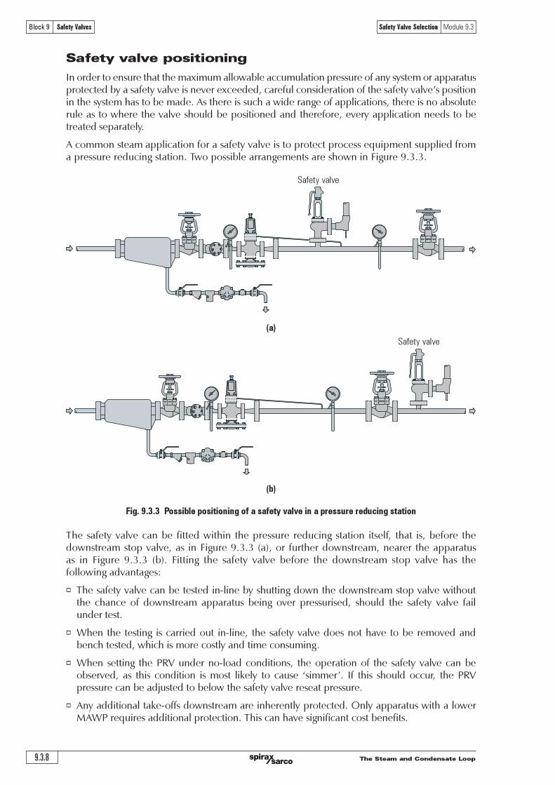
Fig. 9.3.3 Possible positioning of a safety valve in a pressure reducing station
(a)
Safety valve positioning
In order to ensure that the maximum allowable accumulation pressure of any system or apparatusprotected by a safety valve is never exceeded, careful consideration of the safety valve�s positionin the system has to be made. As there is such a wide range of applications, there is no absoluterule as to where the valve should be positioned and therefore, every application needs to betreated separately.
A common steam application for a safety valve is to protect process equipment supplied froma pressure reducing station. Two possible arrangements are shown in Figure 9.3.3.
The safety valve can be fitted within the pressure reducing station itself, that is, before thedownstream stop valve, as in Figure 9.3.3 (a), or further downstream, nearer the apparatusas in Figure 9.3.3 (b). Fitting the safety valve before the downstream stop valve has thefollowing advantages:
o The safety valve can be tested in-line by shutting down the downstream stop valve withoutthe chance of downstream apparatus being over pressurised, should the safety valve failunder test.
o When the testing is carried out in-line, the safety valve does not have to be removed andbench tested, which is more costly and time consuming.
o When setting the PRV under no-load conditions, the operation of the safety valve can beobserved, as this condition is most likely to cause �simmer�. If this should occur, the PRVpressure can be adjusted to below the safety valve reseat pressure.
o Any additional take-offs downstream are inherently protected. Only apparatus with a lowerMAWP requires additional protection. This can have significant cost benefits.
Safety valve
Safety valve
The Steam and Condensate Loop 9.3.9
Block 9 Safety Valves Safety Valve Selection Module 9.3
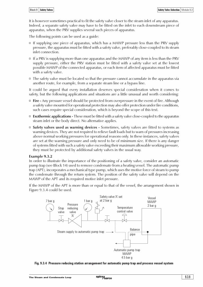
Fig. 9.3.4 Pressure reducing station arrangement for automatic pump trap and process vessel system
It is however sometimes practical to fit the safety valve closer to the steam inlet of any apparatus.Indeed, a separate safety valve may have to be fitted on the inlet to each downstream piece ofapparatus, when the PRV supplies several such pieces of apparatus.
The following points can be used as a guide:
o If supplying one piece of apparatus, which has a MAWP pressure less than the PRV supplypressure, the apparatus must be fitted with a safety valve, preferably close-coupled to its steaminlet connection.
o If a PRV is supplying more than one apparatus and the MAWP of any item is less than the PRVsupply pressure, either the PRV station must be fitted with a safety valve set at the lowestpossible MAWP of the connected apparatus, or each item of affected apparatus must be fittedwith a safety valve.
o The safety valve must be located so that the pressure cannot accumulate in the apparatus viaanother route, for example, from a separate steam line or a bypass line.
It could be argued that every installation deserves special consideration when it comes tosafety, but the following applications and situations are a little unusual and worth considering:
o Fire - Any pressure vessel should be protected from overpressure in the event of fire. Althougha safety valve mounted for operational protection may also offer protection under fire conditions,such cases require special consideration, which is beyond the scope of this text.
o Exothermic applications - These must be fitted with a safety valve close-coupled to the apparatussteam inlet or the body direct. No alternative applies.
o Safety valves used as warning devices - Sometimes, safety valves are fitted to systems aswarning devices. They are not required to relieve fault loads but to warn of pressures increasingabove normal working pressures for operational reasons only. In these instances, safety valvesare set at the warning pressure and only need to be of minimum size. If there is any dangerof systems fitted with such a safety valve exceeding their maximum allowable working pressure,they must be protected by additional safety valves in the usual way.
Example 9.3.2In order to illustrate the importance of the positioning of a safety valve, consider an automaticpump trap (see Block 14) used to remove condensate from a heating vessel. The automatic pumptrap (APT), incorporates a mechanical type pump, which uses the motive force of steam to pumpthe condensate through the return system. The position of the safety valve will depend on theMAWP of the APT and its required motive inlet pressure.
If the MAWP of the APT is more than or equal to that of the vessel, the arrangement shown inFigure 9.3.4 could be used.
7 bar g
Stopvalve
Pressurereducing
valve�A�
1 bar g
Safety valve �A� setat 2 bar g
Temperaturecontrol valve
VesselMAWP2 bar g
Steam supply to automatic pump trapBalance
pipe
Automatic pump trapMAWP
4!5 bar g

The Steam and Condensate Loop
Safety Valve Selection Module 9.3
9.3.10
Block 9 Safety Valves
Fig. 9.3.5 The automatic pump trap and vessel system using two PRV stations
This arrangement is suitable if the pump-trap motive pressure is less than 1.6 bar g (safety valveset pressure of 2 bar g less 0.3 bar blowdown and a 0.1 bar shut-off margin). Since the MAWPof both the APT and the vessel are greater than the safety valve set pressure, a single safetyvalve would provide suitable protection for the system.
However, if the pump-trap motive pressure had to be greater than 1.6 bar g, the APT supplywould have to be taken from the high pressure side of the PRV, and reduced to a moreappropriate pressure, but still less than the 4.5 bar g MAWP of the APT. The arrangementshown in Figure 9.3.5 would be suitable in this situation.
Here, two separate PRV stations are used each with its own safety valve. If the APT internalsfailed and steam at 4 bar g passed through the APT and into the vessel, safety valve �A� wouldrelieve this pressure and protect the vessel. Safety valve �B� would not lift as the pressure in theAPT is still acceptable and below its set pressure.
It should be noted that safety valve �A� is positioned on the downstream side of the temperaturecontrol valve; this is done for both safety and operational reasons:
o Safety - If the internals of the APT failed, the safety valve would still relieve the pressure in thevessel even if the control valve were shut.
o Operation - There is less chance of safety valve �A� simmering during operation in this position,as the pressure is typically lower after the control valve than before it.
Also, note that if the MAWP of the pump-trap were greater than the pressure upstream ofPRV �A�, it would be permissible to omit safety valve �B� from the system, but safety valve �A� mustbe sized to take into account the total fault flow through PRV �B� as well as through PRV �A�.
7 bar g
Stopvalve
Pressurereducing
valve �A�
1 bar g Safety valve �A�set at 2 bar g
VesselMAWP2 bar g
Steam supply toAutomatic pump trap
Balance
pipe
Automatic pump trapMAWP
4!5 bar g
Pressurereducing
valve�B�
set at3 bar g
Safetyvalve
�B�set at
4!5 bar g
Condensatedrain line
Temperaturecontrol valve
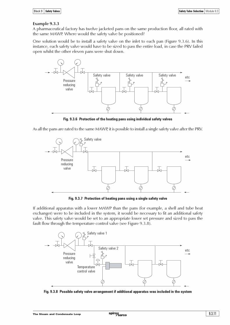
The Steam and Condensate Loop 9.3.11
Block 9 Safety Valves Safety Valve Selection Module 9.3
Example 9.3.3A pharmaceutical factory has twelve jacketed pans on the same production floor, all rated withthe same MAWP. Where would the safety valve be positioned?
One solution would be to install a safety valve on the inlet to each pan (Figure 9.3.6). In thisinstance, each safety valve would have to be sized to pass the entire load, in case the PRV failedopen whilst the other eleven pans were shut down.
As all the pans are rated to the same MAWP, it is possible to install a single safety valve after the PRV.
Fig. 9.3.6 Protection of the heating pans using individual safety valves
Fig. 9.3.7 Protection of heating pans using a single safety valve
If additional apparatus with a lower MAWP than the pans (for example, a shell and tube heatexchanger) were to be included in the system, it would be necessary to fit an additional safetyvalve. This safety valve would be set to an appropriate lower set pressure and sized to pass thefault flow through the temperature control valve (see Figure 9.3.8).
Fig. 9.3.8 Possible safety valve arrangement if additional apparatus was included in the system
Pressurereducing
valve
etc
Pressurereducing
valve
etc
Pressurereducing
valve
etcSafety valve 2
Temperaturecontrol valve
Safety valve Safety valve Safety valve
Safety valve
Safety valve 1

The Steam and Condensate Loop
Safety Valve Selection Module 9.3
9.3.12
Block 9 Safety Valves
Questions
1. Which of the following are the most important criteria in determiningthe set pressure of a safety valve?
i. The MAWP of the system must never be exceeded
ii. The MAAP of the system must never be exceeded
iii. The NWP of the system must never be exceeded
a| i only ¨
b| ii only ¨
c| i and ii ¨
d| i, ii and iii ¨
2. The manufacturer of a heating vessel states that the maximum allowableworking pressure (MAWP) of the vessel is 6.0 bar g, and the maximumallowable accumulation pressure is 6.3 bar g (5% of the MAWP).
If a safety valve used to protect the vessel has an overpressure of 10%,which set pressure would be selected?
a| 5.7 bar ¨
b| 6.0 bar ¨
c| 6.3 bar ¨
d| 6.5 bar ¨
3. Determine the set pressure of a safety valve to be installed in apressure reducing valve station, given the following conditions andensuring that the set pressure is as close to the PRV working pressure as possible:
Normal working pressure 7.4 bar g
PRV proportional band 0.2 bar
Blowdown 5%
MAWP of downstream apparatus 8.5 bar g
a| 8.0 bar ¨
b| 8.1 bar ¨
c| 8.2 bar ¨
d| 8.5 bar ¨
4. The required set pressure of a conventional safety valve is 8.5 bar g,if however, the valve experiences a constant backpressure of 1.0 bar g, atwhich pressure should the valve be set on the test stand?
a| 7.5 bar ¨
b| 8.5 bar ¨
c| 9.5 bar ¨
d| 10.5 bar ¨

The Steam and Condensate Loop 9.3.13
Block 9 Safety Valves Safety Valve Selection Module 9.3
Answers 1:b, 2: a, 3: b, 4: a, 5: d, 6: d5. Which location would be the most appropriate position for a safety valve
installed to protect a single temperature controlled heating vessel?
a| A ¨
b| B ¨
c| C ¨
d| D ¨
6. Who is permitted to adjust the settings of a safety valve approved by anotified body, to a specific standard?
a| Any suitable person provided with the necessary tools ¨
b| Only the certifying body ¨
c| Only the manufacturer ¨
d| The manufacturer or an agent approved by the manufacturer ¨
A B C D
Stopvalve
Stopvalve
Controlvalve
Heating vessel
Pressurereducing
valve

The Steam and Condensate Loop
Safety Valve Selection Module 9.3
9.3.14
Block 9 Safety Valves

The Steam and Condensate Loop 9.4.1
Block 9 Safety Valves Safety Valve Sizing Module 9.4
Module 9.4Safety Valve Sizing
SC
-GC
M-7
1
CM
Iss
ue 4
©
Cop
yri
ght
20
07
Sp
irax-
Sarc
o L
imit
ed

The Steam and Condensate Loop9.4.2
Block 9 Safety Valves Safety Valve Sizing Module 9.4
Safety Valve Sizing
A safety valve must always be sized and able to vent any source of steam so that the pressurewithin the protected apparatus cannot exceed the maximum allowable accumulated pressure(MAAP). This not only means that the valve has to be positioned correctly, but that it is alsocorrectly set. The safety valve must then also be sized correctly, enabling it to pass the requiredamount of steam at the required pressure under all possible fault conditions.
Once the type of safety valve has been established, along with its set pressure and its position in thesystem, it is necessary to calculate the required discharge capacity of the valve. Once this is known,the required orifice area and nominal size can be determined using the manufacturer�s specifications.
In order to establish the maximum capacity required, the potential flow through all the relevantbranches, upstream of the valve, need to be considered.
In applications where there is more than one possible flow path, the sizing of the safety valvebecomes more complicated, as there may be a number of alternative methods of determining itssize. Where more than one potential flow path exists, the following alternatives should be considered:
o The safety valve can be sized on the maximum flow experienced in the flow path with thegreatest amount of flow.
o The safety valve can be sized to discharge the flow from the combined flow paths.
This choice is determined by the risk of two or more devices failing simultaneously. If there is theslightest chance that this may occur, the valve must be sized to allow the combined flows of thefailed devices to be discharged. However, where the risk is negligible, cost advantages may dictatethat the valve should only be sized on the highest fault flow. The choice of method ultimately lieswith the company responsible for insuring the plant.
For example, consider the pressure vessel and automatic pump-trap (APT) system as shown inFigure 9.4.1. The unlikely situation is that both the APT and pressure reducing valve (PRV �A�)could fail simultaneously. The discharge capacity of safety valve �A� would either be the faultload of the largest PRV, or alternatively, the combined fault load of both the APT and PRV �A�.
This document recommends that where multiple flow paths exist, any relevant safety valve should,at all times, be sized on the possibility that relevant upstream pressure control valves may failsimultaneously.
Fig. 9.4.1 An automatic pump-trap and pressure vessel system
7 bar g
Stopvalve
PRV �A�set at
0!5 bar g
0!5 bar gSafety valve �A�set at 0!6 bar g
Pressure vesselMAWP
0!7 bar g
Steam supply to APT Balance
pipe
APT10MAWP
4!5 bar g
PRV �B�set at3 bar g
Safetyvalve
�B�set at4 bar g
7 bar g 3 bar g
Condensatedrain line
Steam
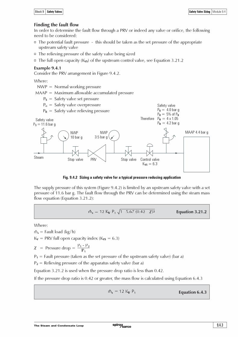
The Steam and Condensate Loop 9.4.3
Block 9 Safety Valves Safety Valve Sizing Module 9.4
NWP10 bar g
NWP3!5 bar g
PRVStop valve Control valveKvs = 6!3
MAAP 4!4 bar g
Stop valve
Fig. 9.4.2 Sizing a safety valve for a typical pressure reducing application
Finding the fault flowIn order to determine the fault flow through a PRV or indeed any valve or orifice, the followingneed to be considered:
o The potential fault pressure - this should be taken as the set pressure of the appropriateupstream safety valve
o The relieving pressure of the safety valve being sized
o The full open capacity (KVS) of the upstream control valve, see Equation 3.21.2
Example 9.4.1Consider the PRV arrangement in Figure 9.4.2.
Where:
NWP = Normal working pressure
MAAP = Maximum allowable accumulated pressure
PS = Safety valve set pressure
Po = Safety valve overpressure
PR = Safety valve relieving pressure
Equation 3.21.2
The supply pressure of this system (Figure 9.4.2) is limited by an upstream safety valve with a setpressure of 11.6 bar g. The fault flow through the PRV can be determined using the steam massflow equation (Equation 3.21.2):
Where:
ms = Fault load (kg / h)
KV = PRV full open capacity index (KVS = 6.3)
χ = Pressure drop =
P1 = Fault pressure (taken as the set pressure of the upstream safety valve) (bar a)
P2 = Relieving pressure of the apparatus safety valve (bar a)
Equation 3.21.2 is used when the pressure drop ratio is less than 0.42.
If the pressure drop ratio is 0.42 or greater, the mass flow is calculated using Equation 6.4.3
Equation 6.4.3 ! "# $ %
!
Steam
Safety valvePs =11!6 bar g
χ ! "# $ % " & '()* +,(-# & .
! "
Safety valvePS = 4!0 bar gPO = 5% of PS
Therefore PR = 4 x 1!05PR = 4!2 bar g
!"!
!
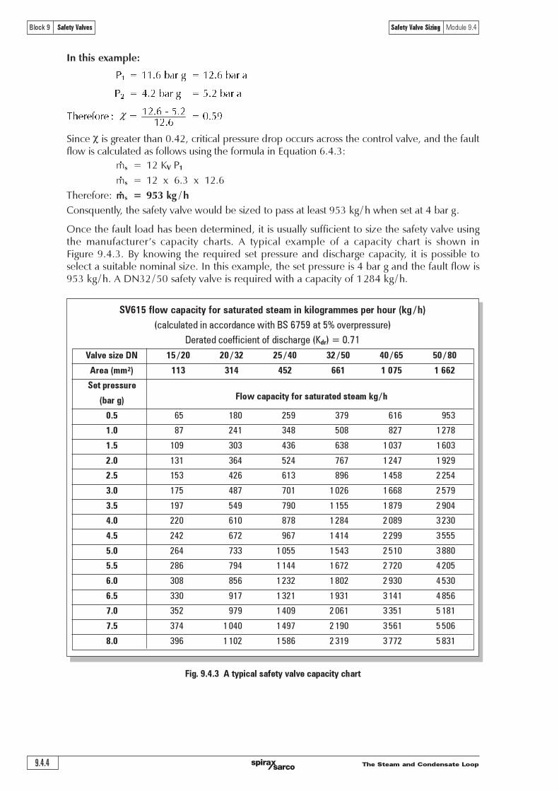
The Steam and Condensate Loop9.4.4
Block 9 Safety Valves Safety Valve Sizing Module 9.4
Fig. 9.4.3 A typical safety valve capacity chart
SV615 flow capacity for saturated steam in kilogrammes per hour (kg / h)
(calculated in accordance with BS 6759 at 5% overpressure)
Derated coefficient of discharge (Kdr) = 0.71
Valve size DN 15 / 20 20 / 32 25 / 40 32 / 50 40 / 65 50 / 80
Area (mm2) 113 314 452 661 1 075 1 662
Set pressure
(bar g) Flow capacity for saturated steam kg / h
0.5 65 180 259 379 616 953
1.0 87 241 348 508 827 1 278
1.5 109 303 436 638 1 037 1 603
2.0 131 364 524 767 1 247 1 929
2.5 153 426 613 896 1 458 2 254
3.0 175 487 701 1 026 1 668 2 579
3.5 197 549 790 1 155 1 879 2 904
4.0 220 610 878 1 284 2 089 3 230
4.5 242 672 967 1 414 2 299 3 555
5.0 264 733 1 055 1 543 2 510 3 880
5.5 286 794 1 144 1 672 2 720 4 205
6.0 308 856 1 232 1 802 2 930 4 530
6.5 330 917 1 321 1 931 3 141 4 856
7.0 352 979 1 409 2 061 3 351 5 181
7.5 374 1 040 1 497 2 190 3 561 5 506
8.0 396 1 102 1 586 2 319 3 772 5 831
Since c is greater than 0.42, critical pressure drop occurs across the control valve, and the faultflow is calculated as follows using the formula in Equation 6.4.3:
ms = 12 KV P1
ms = 12 x 6.3 x 12.6
Therefore: ms = 953 kg / h
Consquently, the safety valve would be sized to pass at least 953 kg / h when set at 4 bar g.
Once the fault load has been determined, it is usually sufficient to size the safety valve usingthe manufacturer�s capacity charts. A typical example of a capacity chart is shown inFigure 9.4.3. By knowing the required set pressure and discharge capacity, it is possible toselect a suitable nominal size. In this example, the set pressure is 4 bar g and the fault flow is953 kg /h. A DN32 /50 safety valve is required with a capacity of 1284 kg /h.
In this example:
! ""#$%&'(%)% !%"*#$%&'(%'
! +#*%&'(%)% !%,#*%&'(%'
"*#$%-%,#*
./0(012(0 3 % !% !%4#,5
"*#$
!
χ
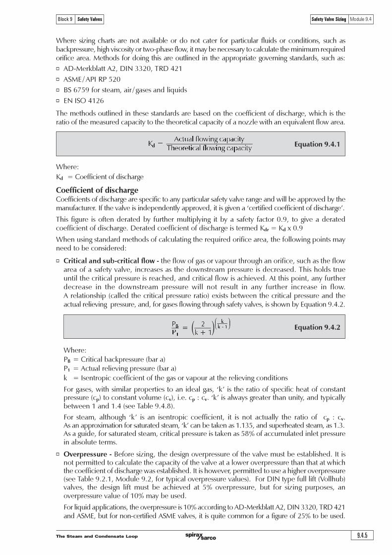
The Steam and Condensate Loop 9.4.5
Block 9 Safety Valves Safety Valve Sizing Module 9.4
Equation 9.4.1 !"#$%&'%()*+,&!$-$!*".
/ &0&
123(43"*!$%&'%()*+,&!$-$!*".
Where sizing charts are not available or do not cater for particular fluids or conditions, such asbackpressure, high viscosity or two-phase flow, it may be necessary to calculate the minimum requiredorifice area. Methods for doing this are outlined in the appropriate governing standards, such as:
o AD-Merkblatt A2, DIN 3320, TRD 421
o ASME / API RP 520
o BS 6759 for steam, air / gases and liquids
o EN ISO 4126
The methods outlined in these standards are based on the coefficient of discharge, which is theratio of the measured capacity to the theoretical capacity of a nozzle with an equivalent flow area.
Where:
Kd = Coefficient of discharge
Coefficient of dischargeCoefficients of discharge are specific to any particular safety valve range and will be approved by themanufacturer. If the valve is independently approved, it is given a �certified coefficient of discharge�.
This figure is often derated by further multiplying it by a safety factor 0.9, to give a deratedcoefficient of discharge. Derated coefficient of discharge is termed Kdr = Kd x 0.9
When using standard methods of calculating the required orifice area, the following points mayneed to be considered:
o Critical and sub-critical flow - the flow of gas or vapour through an orifice, such as the flowarea of a safety valve, increases as the downstream pressure is decreased. This holds trueuntil the critical pressure is reached, and critical flow is achieved. At this point, any furtherdecrease in the downstream pressure will not result in any further increase in flow.A relationship (called the critical pressure ratio) exists between the critical pressure and theactual relieving pressure, and, for gases flowing through safety valves, is shown by Equation 9.4.2.
Equation 9.4.2( ) !
!
"#"
$"%"&
!
"
"
Where:PB = Critical backpressure (bar a)P1 = Actual relieving pressure (bar a)
k = Isentropic coefficient of the gas or vapour at the relieving conditions
For gases, with similar properties to an ideal gas, �k� is the ratio of specific heat of constantpressure (cp) to constant volume (cv), i.e. cp : cv. �k� is always greater than unity, and typicallybetween 1 and 1.4 (see Table 9.4.8).
For steam, although �k� is an isentropic coefficient, it is not actually the ratio of cp : cv.As an approximation for saturated steam, �k� can be taken as 1.135, and superheated steam, as 1.3.As a guide, for saturated steam, critical pressure is taken as 58% of accumulated inlet pressurein absolute terms.
o Overpressure - Before sizing, the design overpressure of the valve must be established. It isnot permitted to calculate the capacity of the valve at a lower overpressure than that at whichthe coefficient of discharge was established. It is however, permitted to use a higher overpressure(see Table 9.2.1, Module 9.2, for typical overpressure values). For DIN type full lift (Vollhub)valves, the design lift must be achieved at 5% overpressure, but for sizing purposes, anoverpressure value of 10% may be used.
For liquid applications, the overpressure is 10% according to AD-Merkblatt A2, DIN 3320, TRD 421and ASME, but for non-certified ASME valves, it is quite common for a figure of 25% to be used.
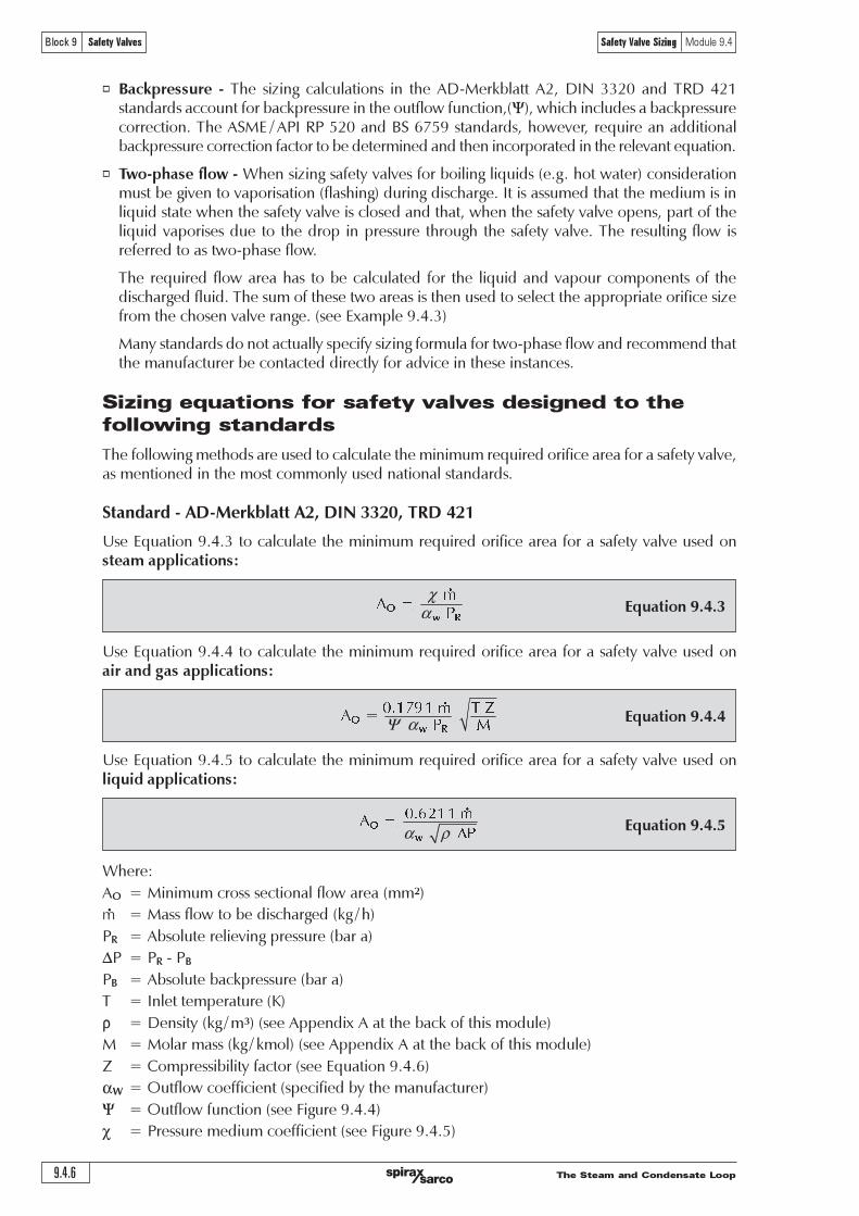
The Steam and Condensate Loop9.4.6
Block 9 Safety Valves Safety Valve Sizing Module 9.4
Equation 9.4.3
! "
#
! "
χα
Use Equation 9.4.4 to calculate the minimum required orifice area for a safety valve used onair and gas applications:
Equation 9.4.4
Use Equation 9.4.5 to calculate the minimum required orifice area for a safety valve used onliquid applications:
Equation 9.4.5
Where:
AO = Minimum cross sectional flow area (mm2)
m = Mass flow to be discharged (kg / h)
PR = Absolute relieving pressure (bar a)
DP = PR - PB
PB = Absolute backpressure (bar a)
T = Inlet temperature (K)
r = Density (kg / m3) (see Appendix A at the back of this module)
M = Molar mass (kg / kmol) (see Appendix A at the back of this module)
Z = Compressibility factor (see Equation 9.4.6)
aW = Outflow coefficient (specified by the manufacturer)
Y = Outflow function (see Figure 9.4.4)
c = Pressure medium coefficient (see Figure 9.4.5)
o Backpressure - The sizing calculations in the AD-Merkblatt A2, DIN 3320 and TRD 421standards account for backpressure in the outflow function,(Y), which includes a backpressurecorrection. The ASME / API RP 520 and BS 6759 standards, however, require an additionalbackpressure correction factor to be determined and then incorporated in the relevant equation.
o Two-phase flow - When sizing safety valves for boiling liquids (e.g. hot water) considerationmust be given to vaporisation (flashing) during discharge. It is assumed that the medium is inliquid state when the safety valve is closed and that, when the safety valve opens, part of theliquid vaporises due to the drop in pressure through the safety valve. The resulting flow isreferred to as two-phase flow.
The required flow area has to be calculated for the liquid and vapour components of thedischarged fluid. The sum of these two areas is then used to select the appropriate orifice sizefrom the chosen valve range. (see Example 9.4.3)
Many standards do not actually specify sizing formula for two-phase flow and recommend thatthe manufacturer be contacted directly for advice in these instances.
Sizing equations for safety valves designed to the
following standards
The following methods are used to calculate the minimum required orifice area for a safety valve,as mentioned in the most commonly used national standards.
Standard - AD-Merkblatt A2, DIN 3320, TRD 421
Use Equation 9.4.3 to calculate the minimum required orifice area for a safety valve used onsteam applications:
!"#$"% &%'
( %)% %
% %* +
! "
Ψ α
!"#$$%
& %'%
% % (
!
α ρ

The Steam and Condensate Loop 9.4.7
Block 9 Safety Valves Safety Valve Sizing Module 9.4
Fig. 9.4.4 The outflow function (Y) as used in AD-Merkblatt A2, DIN 3320 and TRD 421
0.6
0.5
0.4
0.3
0.2
0.1
00.2 0.3 0.4 0.5 0.6 0.7 0.8 0.9 1.0
k
1.8
1.6
1.4
1.2
1.0
Y max.
0.527
0.507
0.484
0.459
0.429
The outflow function (Y) for air and gas applications
Ou
tflo
w f
un
cti
on
Y
Pressure ratio (PB / PR)
PB = Absolute backpressure
PR = Absolute relieving pressure

The Steam and Condensate Loop9.4.8
Block 9 Safety Valves Safety Valve Sizing Module 9.4
Fig. 9.4.5 Pressure medium coefficient (c) for steam as used in
AD-Merkblatt A2, DIN 3320, TRD 421
2.8
2.6
2.4
2.2
2.0
1.8
1.6
1.4
700°C
600°C
500°C
400°C
300°C
200°C
1 2 3 4 5 10 20 30 40 50 100 200 300 400
Saturated steam
Pressure medium coefficient (c) for steam applications
Pre
ssu
re m
ed
ium
co
eff
icie
nt
(c)
Set pressure (bar a)

The Steam and Condensate Loop 9.4.9
Block 9 Safety Valves Safety Valve Sizing Module 9.4
Equation 9.4.6 ! "# "$"
%"&"
' "(
!
"
ν
Consequently, the chosen safety valve would need an orifice area of at least 1 678 mm2.
Compressibility factor (Z)For gases, the compressibility factor, Z, also needs to be determined. This factor accounts for thedeviation of the actual gas from the characteristics of an ideal gas. It is often recommended thatZ = 1 is used where insufficient data is available. Z can be calculated by using the formula inEquation 9.4.6:
Where:
Z = Compressibility factor
PR = Safety valve relieving pressure (bar a)
n = Specific volume of the gas at the actual relieving pressure and temperature (m3 / kg)
(see Appendix A at the back of this module). Note: The specific volume of a gas
will change with temperature and pressure, and therefore it must be determined for the
operating conditions.
M = Molar mass (kg / kmol) (see Appendix A at the back of this module)
Ru = Universal gas constant (8 314 Nm / kmol K)
T = Actual relieving temperature (K)
Example 9.4.2Determine the minimum required safety valve orifice area under the following conditions:
Medium: Saturated steamDischarge quantity (m): 2 500 kg / h
Set pressure (Ps): 4 bar aBackpressure: Atmospheric pressure 1 bar a
Stated outflow coefficient (aw): 0.7
It is first necessary to determine the pressure medium coefficient using Figure 9.4.5.
Pressure medium coefficient (c): 1.88
Using Equation 9.4.3: !
" #
! $
%&'' ! ()**
*&+ ! ,
! "
! " " # $%& ''
χα
Therefore:

The Steam and Condensate Loop9.4.10
Block 9 Safety Valves Safety Valve Sizing Module 9.4
Equation 9.4.7
!"!
#!$!
! "
#"
Where:
n = The proportion of discharge fluid which is vapour
hf1 = Enthalpy of liquid before the valve (kJ / kg)
hf2 = Enthalpy of liquid after the valve (kJ / kg)
hfg2 = Enthalpy of evaporation after the valve (kJ / kg)
For hot water, the enthalpy values can be obtained from steam tables.
In order to determine the proportion of flow, which is vapour, the discharge capacity is multipliedby n. The remainder of the flow will therefore be in the liquid state.
The area sizing calculation from Equations 9.4.3, 9.4.4 and 9.4.5 can then be used to calculatethe required area to discharge the vapour portion and then the liquid portion. The sum of theseareas is then used to establish the minimum required orifice area.
Example 9.4.3Consider hot water under the following conditions:
Temperature: 160°CDischarge quantity (m): 3 900 kg / h
Set pressure (PS): 10 bar g = 11 bar aBackpressure (PB): Atmospheric
Density of water at 160°C (r): 908 kg /m³DP = PS - PB: 10 bar
Stated outflow coefficient (aw): 0.7
Using steam tables, the proportion of vapour is first calculated:
hf1 = 675 kJ / kg (at 160°C)hf2 = 417 kJ / kg (at 1 bar a, atmospheric pressure)
hfg2 = 2 258 kJ / kg (at 1 bar a, atmospheric pressure)
Using Equation 9.4.7:
Two-phase flowIn order to determine the minimum orifice area for a two-phase flow system (e.g. hot water), it isfirst necessary to establish what proportion of the discharge will be vapour (n). This is done usingthe Equation 9.4.7:
!"!
# $
%&'!"!()&
* +,+-.,+ /!# $ !$!01))( 2
3!3'4
! "
#"
Capacity discharge as vapour (steam) = 0.114 3 x 3 900 kg / h = 446 kg / h
Capacity discharge as liquid (water) = 3 900 kg / h - 446 kg / h = 3 454 kg / h
Calculated area for vapour portion:
Using Equation 9.4.3: (where c = Pressure medium coefficientat the set pressure)
!"#$%
! "
#
$%&' ( ))*
+,-.-/0.- 1 ! " " $$$ 22
3%4 ( $$
! "
#
χα

The Steam and Condensate Loop 9.4.11
Block 9 Safety Valves Safety Valve Sizing Module 9.4
Equation 9.4.8
Use Equation 9.4.9 to calculate the minimum required orifice area for a safety valve used onair and gas applications:
Equation 9.4.9 ! " #
$ %
&'&() * + , +
! " # $
Use Equation 9.4.10 to calculate the minimum required orifice area for a safety valve used onliquid applications:
Equation 9.4.10
! "#" ""
$%"& "& "& ' "("'
!
" # $ %
Where:
AO = Required effective discharge area (in2)
m = Required mass flow through the valve (lb / h)
V = Required volume flow through the valve (ft3 / min)
V1 = Required volume flow through the valve (U.S. gal / min)
PR = Upstream relieving pressure (psi a)
PB = Absolute backpressure (psi a)
Cg = Nozzle gas constant (see Table 9.4.1)
T = Relieving temperature (°R º °F + 460)
G = Specific gravity (ratio of molar mass of the fluid to the molar mass of air (28.96 kg / kmol))
(see Appendix A at the back of this module)
Z = Compressibility factor (see Equation 9.4.6)
Kd = Effective coefficient of discharge (specified by the manufacturer)
KSH = Superheat correction factor (see Table 9.4.2)
KB = Backpressure correction factor for gas and vapour (see Figures 9.4.6 and 9.4.7)
KW = Backpressure correction factor for liquids (bellows balanced valves only) (see Figure 9.4.8)
Kµ = Viscosity factor (see Figure 9.4.9)
!"! !
#$%#!& !' !'
! " #$
Total required discharge area = 111 + 33 = 144 mm2
Therefore, a valve must be selected with a discharge area greater than 144 mm2.
Standard - ASME / API RP 520The following formulae are used for calculating the minimum required orifice area for a safetyvalve according to ASME standards and the API RP 520 guidelines.
Use Equation 9.4.8 to calculate the minimum required orifice area for a safety valve used onsteam applications:
Calculated area for liquid portion:
Using Equation 9.4.5:
!"#$"%
!"#$$%&%
' (
% % )
!"#$$%%&%%*%+,+
-./0/120/ 3% ' ( %(%**%44
!5% 6 7%%&%%$
!
"
α ρ

The Steam and Condensate Loop9.4.12
Block 9 Safety Valves Safety Valve Sizing Module 9.4
Nozzle gas constant for ASME / API RP 520
Table 9.4.1 Nozzle gas constant (Cg) relative to isentropic constant (k) for air and gases
k Cg k Cg k Cg k Cg
1.01 317 1.26 343 1.51 365 1.76 384
1.02 318 1.27 344 1.52 366 1.77 385
1.03 319 1.28 345 1.53 367 1.78 386
1.04 320 1.29 346 1.54 368 1.79 386
1.05 321 1.30 347 1.55 369 1.80 387
1.06 322 1.31 348 1.56 369 1.81 388
1.07 323 1.32 349 1.57 370 1.82 389
1.08 325 1.33 350 1.58 371 1.83 389
1.09 326 1.34 351 1.59 372 1.84 390
1.10 327 1.35 352 1.60 373 1.85 391
1.11 328 1.36 353 1.61 373 1.86 391
1.12 329 1.37 353 1.62 374 1.87 392
1.13 330 1.38 354 1.63 375 1.88 393
1.14 331 1.39 355 1.64 376 1.89 393
1.15 332 1.40 356 1.65 376 1.90 394
1.16 333 1.41 357 1.66 377 1.91 395
1.17 334 1.42 358 1.67 378 1.92 395
1.18 335 1.43 359 1.68 379 1.93 396
1.19 336 1.44 360 1.69 379 1.94 397
1.20 337 1.45 360 1.70 380 1.95 397
1.21 338 1.46 361 1.71 381 1.96 398
1.22 339 1.47 362 1.72 382 1.97 398
1.23 340 1.48 363 1.73 383 1.98 399
1.24 341 1.49 364 1.74 383 1.99 400
1.25 342 1.50 365 1.75 384 2.00 400
( ) ( ) !
"
! "#"$ %" &" " "'()"&"*"+"
&","+
! "#"-+$"'()"&"#"+
!
!
"
"
The nozzle gas constant Cg is calculated using Equation 9.4.11, for air and gas applications andapplied to Equation 9.4.9.
Equation 9.4.11
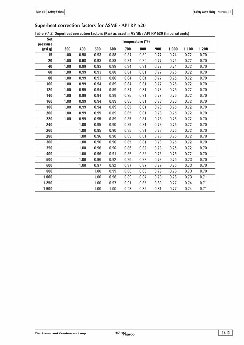
The Steam and Condensate Loop 9.4.13
Block 9 Safety Valves Safety Valve Sizing Module 9.4
Superheat correction factors for ASME / API RP 520
Table 9.4.2 Superheat correction factors (KSH) as used in ASME / API RP 520 (Imperial units)
SetTemperature (°F)
pressure
(psi g) 300 400 500 600 700 800 900 1 000 1 100 1 200
15 1.00 0.98 0.93 0.88 0.84 0.80 0.77 0.74 0.72 0.70
20 1.00 0.98 0.93 0.88 0.84 0.80 0.77 0.74 0.72 0.70
40 1.00 0.99 0.93 0.88 0.84 0.81 0.77 0.74 0.72 0.70
60 1.00 0.99 0.93 0.88 0.84 0.81 0.77 0.75 0.72 0.70
80 1.00 0.99 0.93 0.88 0.84 0.81 0.77 0.75 0.72 0.70
100 1.00 0.99 0.94 0.89 0.84 0.81 0.77 0.75 0.72 0.70
120 1.00 0.99 0.94 0.89 0.84 0.81 0.78 0.75 0.72 0.70
140 1.00 0.99 0.94 0.89 0.85 0.81 0.78 0.75 0.72 0.70
160 1.00 0.99 0.94 0.89 0.85 0.81 0.78 0.75 0.72 0.70
180 1.00 0.99 0.94 0.89 0.85 0.81 0.78 0.75 0.72 0.70
200 1.00 0.99 0.95 0.89 0.85 0.81 0.78 0.75 0.72 0.70
220 1.00 0.99 0.95 0.89 0.85 0.81 0.78 0.75 0.72 0.70
240 1.00 0.95 0.90 0.85 0.81 0.78 0.75 0.72 0.70
260 1.00 0.95 0.90 0.85 0.81 0.78 0.75 0.72 0.70
280 1.00 0.96 0.90 0.85 0.81 0.78 0.75 0.72 0.70
300 1.00 0.96 0.90 0.85 0.81 0.78 0.75 0.72 0.70
350 1.00 0.96 0.90 0.86 0.82 0.78 0.75 0.72 0.70
400 1.00 0.96 0.91 0.86 0.82 0.78 0.75 0.72 0.70
500 1.00 0.96 0.92 0.86 0.82 0.78 0.75 0.73 0.70
600 1.00 0.97 0.92 0.87 0.82 0.79 0.75 0.73 0.70
800 1.00 0.95 0.88 0.83 0.79 0.76 0.73 0.70
1 000 1.00 0.96 0.89 0.84 0.78 0.76 0.73 0.71
1 250 1.00 0.97 0.91 0.85 0.80 0.77 0.74 0.71
1 500 1.00 1.00 0.93 0.86 0.81 0.77 0.74 0.71
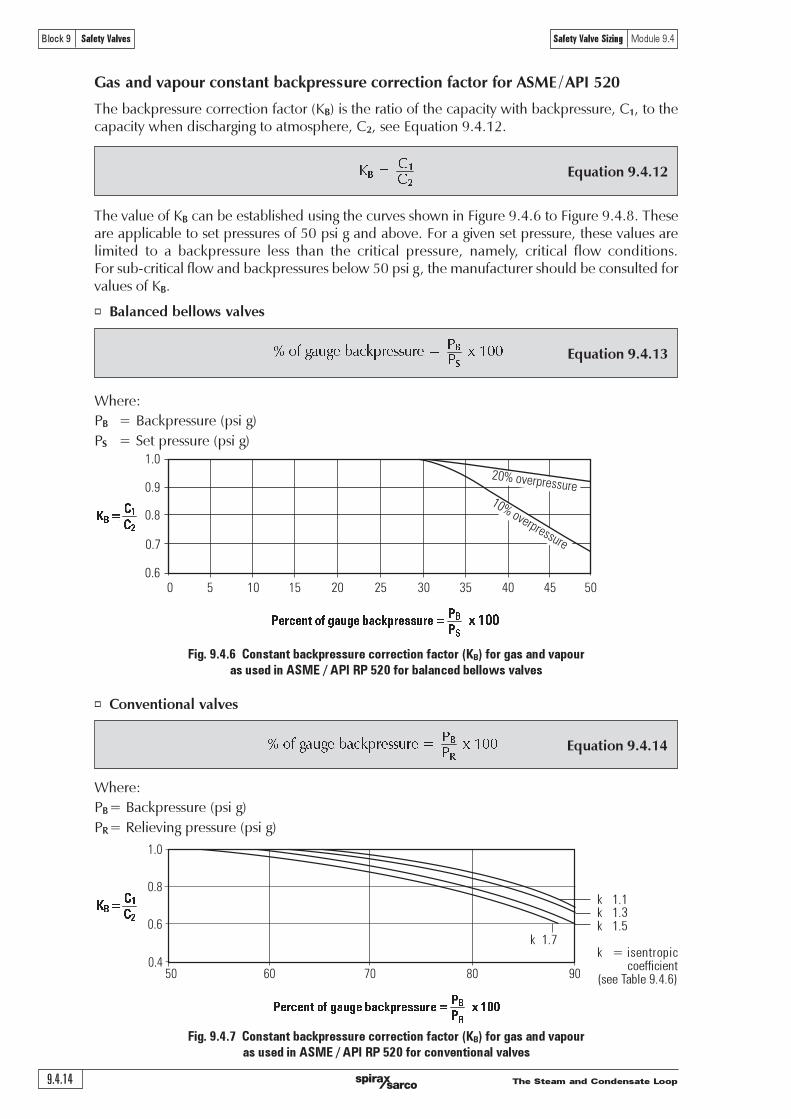
The Steam and Condensate Loop9.4.14
Block 9 Safety Valves Safety Valve Sizing Module 9.4
Equation 9.4.12
! "#"
!
"
Equation 9.4.13
!"#$"%&'%(")&*+,-(..'-("/" "0"122
!
Fig. 9.4.6 Constant backpressure correction factor (KB) for gas and vapour
as used in ASME / API RP 520 for balanced bellows valves
1.0
0.9
0.8
0.7
0.60 5 10 15 20 25 30 35 40 45 50
20% overpressure10% overpressure
Equation 9.4.14
!"#$"%&'%(")&*+,-(..'-("/" "0"122
!
Fig. 9.4.7 Constant backpressure correction factor (KB) for gas and vapour
as used in ASME / API RP 520 for conventional valves
Gas and vapour constant backpressure correction factor for ASME / API 520
The backpressure correction factor (KB) is the ratio of the capacity with backpressure, C1, to thecapacity when discharging to atmosphere, C2, see Equation 9.4.12.
The value of KB can be established using the curves shown in Figure 9.4.6 to Figure 9.4.8. Theseare applicable to set pressures of 50 psi g and above. For a given set pressure, these values arelimited to a backpressure less than the critical pressure, namely, critical flow conditions.For sub-critical flow and backpressures below 50 psi g, the manufacturer should be consulted forvalues of KB.
o Balanced bellows valves
Where:
PB = Backpressure (psi g)
PS = Set pressure (psi g)
Where:
PB= Backpressure (psi g)
PR= Relieving pressure (psi g)
!
!"#!$%&'(&)*+)!&,*#-."!//+"!&0&
!"##
k 1 1k 1 3k 1 5
k = isentropiccoefficient
(see!Table!9 4 6)
!
"
! "#"
!
!"#!$%&'(&)*+)!&,*#-."!//+"!&0& 1&233
k!!1 7
o Conventional valves
!
"
! "#"
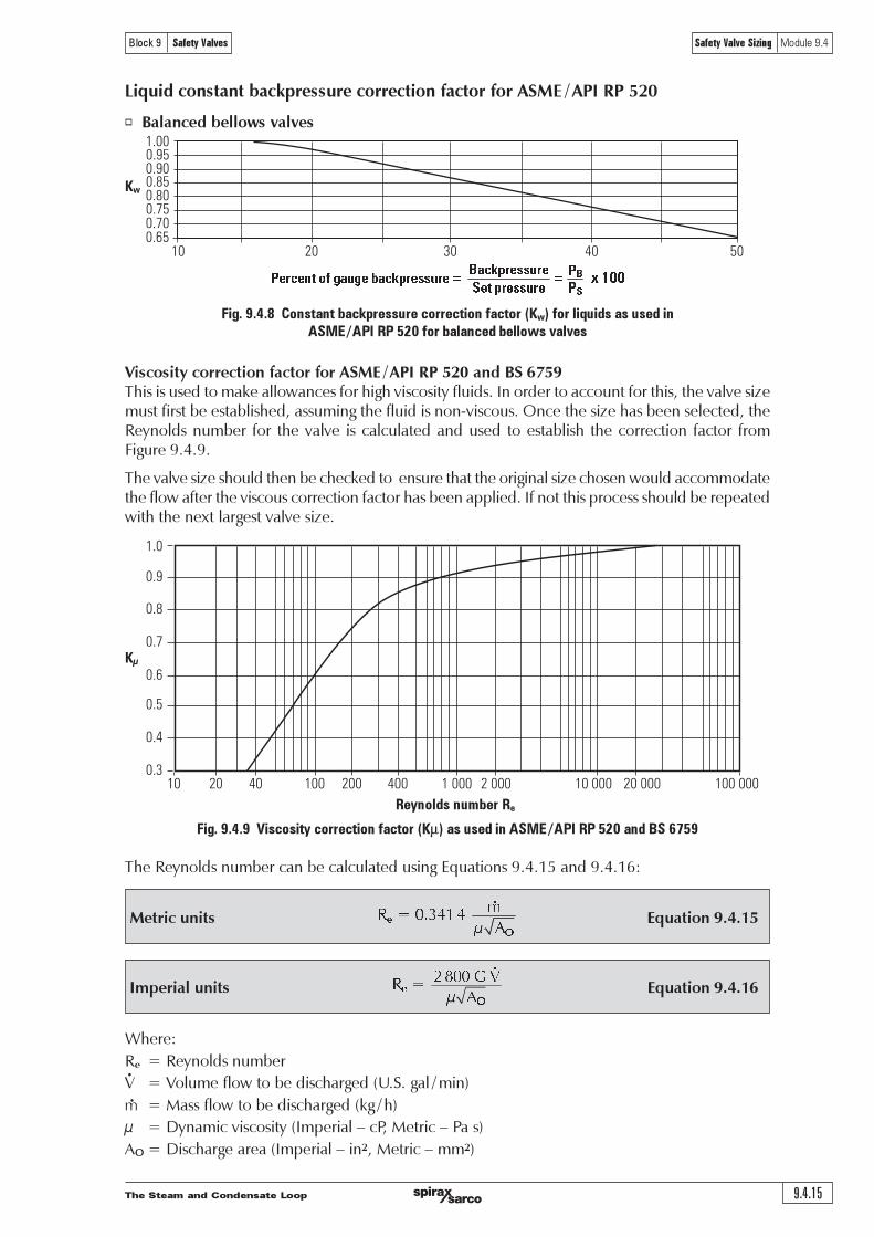
The Steam and Condensate Loop 9.4.15
Block 9 Safety Valves Safety Valve Sizing Module 9.4
Fig. 9.4.8 Constant backpressure correction factor (Kw) for liquids as used in
ASME / API RP 520 for balanced bellows valves
1.00
10 20 30 40 50
0.90
0.80
0.700.65
0.75
0.85
0.95
1.0
0.9
0.8
0.7
0.6
0.5
0.4
0.310 20 40 100 200 400 1 000 2 000 10 000 20 000 100 000
Liquid constant backpressure correction factor for ASME / API RP 520
o Balanced bellows valves
Viscosity correction factor for ASME / API RP 520 and BS 6759This is used to make allowances for high viscosity fluids. In order to account for this, the valve sizemust first be established, assuming the fluid is non-viscous. Once the size has been selected, theReynolds number for the valve is calculated and used to establish the correction factor fromFigure 9.4.9.
The valve size should then be checked to ensure that the original size chosen would accommodatethe flow after the viscous correction factor has been applied. If not this process should be repeatedwith the next largest valve size.
!
!"#$%&''(%&
)
)&%"&*+,-.,/!(/&,0!"#$%&''(%&,1,, 1
2&+,$%&''(%& )
!"##
Kw
Kµ
Fig. 9.4.9 Viscosity correction factor (Km) as used in ASME / API RP 520 and BS 6759
Metric units Equation 9.4.15 !"!#$%&'!&!
( )
!
Imperial units Equation 9.4.16 !"##!$!
% !&!
' (
!
The Reynolds number can be calculated using Equations 9.4.15 and 9.4.16:
Where:
Re = Reynolds number
V = Volume flow to be discharged (U.S. gal / min)
m = Mass flow to be discharged (kg / h)
µ = Dynamic viscosity (Imperial � cP, Metric � Pa s)
AO = Discharge area (Imperial � in2, Metric � mm2)
Reynolds number Re
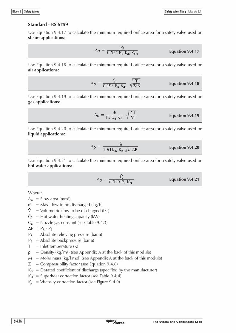
The Steam and Condensate Loop9.4.16
Block 9 Safety Valves Safety Valve Sizing Module 9.4
Standard - BS 6759
Use Equation 9.4.17 to calculate the minimum required orifice area for a safety valve used onsteam applications:
Equation 9.4.17 !"!
#$%&%!' !( !(
! "# $%
Use Equation 9.4.18 to calculate the minimum required orifice area for a safety valve used onair applications:
Equation 9.4.18
! "#" ""
$%&'(") "* +,,
! "#
Use Equation 9.4.19 to calculate the minimum required orifice area for a safety valve used ongas applications:
Equation 9.4.19
Use Equation 9.4.20 to calculate the minimum required orifice area for a safety valve used onliquid applications:
Equation 9.4.20
Use Equation 9.4.21 to calculate the minimum required orifice area for a safety valve used onhot water applications:
Equation 9.4.21 !"!
#$%&'!( !) !
! "#
!"
# !$! !!
% !& !' (
! " #$
Where:
AO = Flow area (mm2)
m = Mass flow to be discharged (kg / h)
V = Volumetric flow to be discharged (l / s)
Q = Hot water heating capacity (kW)
Cg = Nozzle gas constant (see Table 9.4.3)
DP = PR - PB
PR = Absolute relieving pressure (bar a)
PB = Absolute backpressure (bar a)
T = Inlet temperature (K)
r = Density (kg / m3) (see Appendix A at the back of this module)
M = Molar mass (kg / kmol) (see Appendix A at the back of this module)
Z = Compressibility factor (see Equation 9.4.6)
Kdr = Derated coefficient of discharge (specified by the manufacturer)
KSH = Superheat correction factor (see Table 9.4.4)
Kµ = Viscosity correction factor (see Figure 9.4.9)
!"! !
#$%#!& !& ! '
!"
ρ

The Steam and Condensate Loop 9.4.17
Block 9 Safety Valves Safety Valve Sizing Module 9.4
Nozzle gas constant for BS 6759
Table 9.4.3 Nozzle gas constant (Cg) relative to isentropic coefficient (k) for gases
k Cg k Cg k Cg
0.40 1.65 1.02 2.41 1.42 2.72
0.45 1.73 1.04 2.43 1.44 2.73
0.50 1.81 1.06 2.45 1.46 2.74
0.55 1.89 1.08 2.46 1.48 2.76
0.60 1.96 1.10 2.48 1.50 2.77
0.65 2.02 1.12 2.50 1.52 2.78
0.70 2.08 1.14 2.51 1.54 2.79
0.75 2.14 1.16 2.53 1.56 2.80
0.80 2.20 1.18 2.55 1.58 2.82
0.82 2.22 1.20 2.56 1.60 2.83
0.84 2.24 1.22 2.58 1.62 2.84
0.86 2.26 1.24 2.59 1.64 2.85
0.88 2.28 1.26 2.61 1.66 2.86
0.90 2.30 1.28 2.62 1.68 2.87
0.92 2.32 1.30 2.63 1.70 2.89
0.94 2.34 1.32 2.65 1.80 2.94
0.96 2.36 1.34 2.66 1.90 2.99
0.98 2.38 1.36 2.68 2.00 3.04
0.99 2.39 1.38 2.69 2.10 3.09
1.001 2.40 1.40 2.70 2.20 3.13
( )( ) !
!"!
! "#"$%&'(" )" "
)"*"+
!
!
"
The nozzle gas constant Cg is calculated using Equation 9.4.22, for gases, and applied toEquation 9.4.19.
Equation 9.4.22

The Steam and Condensate Loop9.4.18
Block 9 Safety Valves Safety Valve Sizing Module 9.4
Superheat correction factor (KSH) for BS 6759
Table 9.4.4 Superheat correction factors (KSH) as used in BS 6759 (Metric units)
SetTemperature (°C)
pressure
(bar g) 150 200 250 300 350 400 450 500 550 600
2 1.00 0.99 0.94 0.89 0.86 0.82 0.79 0.76 0.74 0.72
3 1.00 0.99 0.94 0.89 0.86 0.82 0.79 0.76 0.74 0.72
4 1.00 0.99 0.94 0.90 0.86 0.82 0.79 0.76 0.74 0.72
5 1.00 0.99 0.94 0.90 0.86 0.82 0.79 0.76 0.74 0.72
6 0.99 0.94 0.90 0.86 0.82 0.79 0.76 0.74 0.72
7 0.99 0.95 0.90 0.86 0.82 0.79 0.77 0.74 0.72
8 1.00 0.95 0.90 0.86 0.82 0.79 0.77 0.74 0.72
9 1.00 0.95 0.90 0.86 0.83 0.79 0.77 0.74 0.72
10 1.00 0.95 0.90 0.86 0.83 0.79 0.77 0.74 0.72
11 1.00 0.95 0.90 0.86 0.83 0.79 0.77 0.74 0.72
12 1.00 0.95 0.90 0.86 0.83 0.79 0.77 0.74 0.72
13 1.00 0.96 0.91 0.86 0.83 0.80 0.77 0.74 0.72
14 1.00 0.96 0.91 0.86 0.83 0.80 0.77 0.74 0.72
16 1.00 0.96 0.91 0.87 0.83 0.80 0.77 0.74 0.72
18 0.96 0.91 0.87 0.83 0.80 0.77 0.74 0.72
20 0.97 0.91 0.87 0.83 0.80 0.77 0.74 0.72
24 0.98 0.92 0.87 0.84 0.80 0.77 0.74 0.72
28 0.99 0.92 0.87 0.84 0.80 0.77 0.75 0.72
34 0.99 0.93 0.88 0.84 0.80 0.77 0.75 0.72
40 1.00 0.94 0.89 0.84 0.81 0.78 0.75 0.72
56 0.96 0.90 0.86 0.81 0.78 0.75 0.73
70 0.98 0.92 0.86 0.82 0.79 0.76 0.73
85 1.00 0.93 0.87 0.83 0.79 0.76 0.73
100 1.00 0.93 0.88 0.84 0.80 0.76 0.74
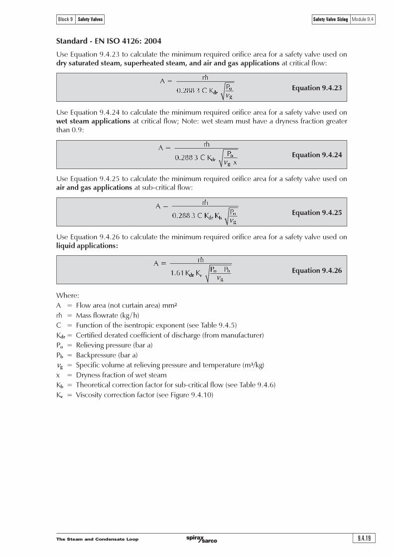
The Steam and Condensate Loop 9.4.19
Block 9 Safety Valves Safety Valve Sizing Module 9.4
Equation 9.4.24
Standard - EN ISO 4126: 2004
Use Equation 9.4.23 to calculate the minimum required orifice area for a safety valve used ondry saturated steam, superheated steam, and air and gas applications at critical flow:
Equation 9.4.23 !"!
#
$%&'' (!)!* !
!"
#
ν
Use Equation 9.4.24 to calculate the minimum required orifice area for a safety valve used onwet steam applications at critical flow; Note: wet steam must have a dryness fraction greaterthan 0.9:
!"!
#
$%&'' (!)!* !
!+
!"
#
ν
Use Equation 9.4.25 to calculate the minimum required orifice area for a safety valve used onair and gas applications at sub-critical flow:
Equation 9.4.25
!"!
#
$%&'' (!)!* * !
!"
#
$
ν
Use Equation 9.4.26 to calculate the minimum required orifice area for a safety valve used onliquid applications:
Equation 9.4.26
!"!
# !$!#
%&'%!( ( !
!
"#
$
%
ν
Where:
A = Flow area (not curtain area) mm2
m = Mass flowrate (kg / h)
C = Function of the isentropic exponent (see Table 9.4.5)
Kdr = Certified derated coefficient of discharge (from manufacturer)
Po = Relieving pressure (bar a)
Pb = Backpressure (bar a)
ng = Specific volume at relieving pressure and temperature (m³/kg)
x = Dryness fraction of wet steam
Kb = Theoretical correction factor for sub-critical flow (see Table 9.4.6)
Kv = Viscosity correction factor (see Figure 9.4.10)
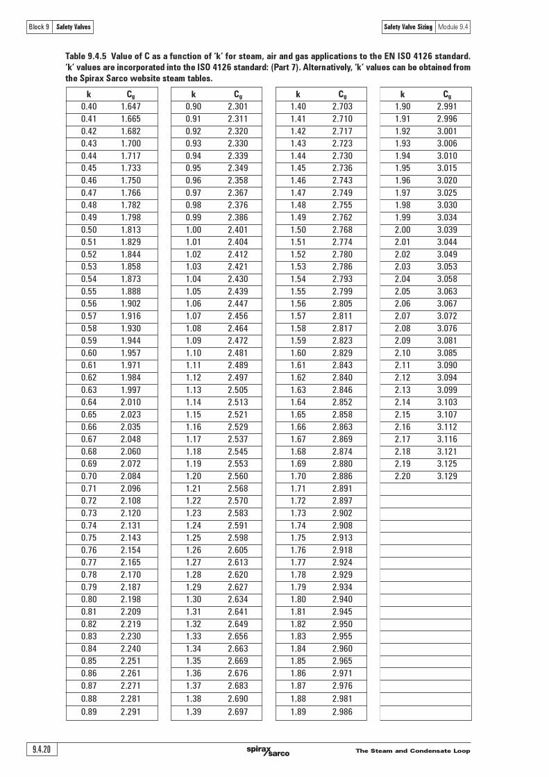
The Steam and Condensate Loop9.4.20
Block 9 Safety Valves Safety Valve Sizing Module 9.4
Table 9.4.5 Value of C as a function of �k� for steam, air and gas applications to the EN ISO 4126 standard.
�k� values are incorporated into the ISO 4126 standard: (Part 7). Alternatively, �k� values can be obtained from
the Spirax Sarco website steam tables.
k Cg k Cg k Cg k Cg
0.40 1.647 0.90 2.301 1.40 2.703 1.90 2.991
0.41 1.665 0.91 2.311 1.41 2.710 1.91 2.996
0.42 1.682 0.92 2.320 1.42 2.717 1.92 3.001
0.43 1.700 0.93 2.330 1.43 2.723 1.93 3.006
0.44 1.717 0.94 2.339 1.44 2.730 1.94 3.010
0.45 1.733 0.95 2.349 1.45 2.736 1.95 3.015
0.46 1.750 0.96 2.358 1.46 2.743 1.96 3.020
0.47 1.766 0.97 2.367 1.47 2.749 1.97 3.025
0.48 1.782 0.98 2.376 1.48 2.755 1.98 3.030
0.49 1.798 0.99 2.386 1.49 2.762 1.99 3.034
0.50 1.813 1.00 2.401 1.50 2.768 2.00 3.039
0.51 1.829 1.01 2.404 1.51 2.774 2.01 3.044
0.52 1.844 1.02 2.412 1.52 2.780 2.02 3.049
0.53 1.858 1.03 2.421 1.53 2.786 2.03 3.053
0.54 1.873 1.04 2.430 1.54 2.793 2.04 3.058
0.55 1.888 1.05 2.439 1.55 2.799 2.05 3.063
0.56 1.902 1.06 2.447 1.56 2.805 2.06 3.067
0.57 1.916 1.07 2.456 1.57 2.811 2.07 3.072
0.58 1.930 1.08 2.464 1.58 2.817 2.08 3.076
0.59 1.944 1.09 2.472 1.59 2.823 2.09 3.081
0.60 1.957 1.10 2.481 1.60 2.829 2.10 3.085
0.61 1.971 1.11 2.489 1.61 2.843 2.11 3.090
0.62 1.984 1.12 2.497 1.62 2.840 2.12 3.094
0.63 1.997 1.13 2.505 1.63 2.846 2.13 3.099
0.64 2.010 1.14 2.513 1.64 2.852 2.14 3.103
0.65 2.023 1.15 2.521 1.65 2.858 2.15 3.107
0.66 2.035 1.16 2.529 1.66 2.863 2.16 3.112
0.67 2.048 1.17 2.537 1.67 2.869 2.17 3.116
0.68 2.060 1.18 2.545 1.68 2.874 2.18 3.121
0.69 2.072 1.19 2.553 1.69 2.880 2.19 3.125
0.70 2.084 1.20 2.560 1.70 2.886 2.20 3.129
0.71 2.096 1.21 2.568 1.71 2.891
0.72 2.108 1.22 2.570 1.72 2.897
0.73 2.120 1.23 2.583 1.73 2.902
0.74 2.131 1.24 2.591 1.74 2.908
0.75 2.143 1.25 2.598 1.75 2.913
0.76 2.154 1.26 2.605 1.76 2.918
0.77 2.165 1.27 2.613 1.77 2.924
0.78 2.170 1.28 2.620 1.78 2.929
0.79 2.187 1.29 2.627 1.79 2.934
0.80 2.198 1.30 2.634 1.80 2.940
0.81 2.209 1.31 2.641 1.81 2.945
0.82 2.219 1.32 2.649 1.82 2.950
0.83 2.230 1.33 2.656 1.83 2.955
0.84 2.240 1.34 2.663 1.84 2.960
0.85 2.251 1.35 2.669 1.85 2.965
0.86 2.261 1.36 2.676 1.86 2.971
0.87 2.271 1.37 2.683 1.87 2.976
0.88 2.281 1.38 2.690 1.88 2.981
0.89 2.291 1.39 2.697 1.89 2.986
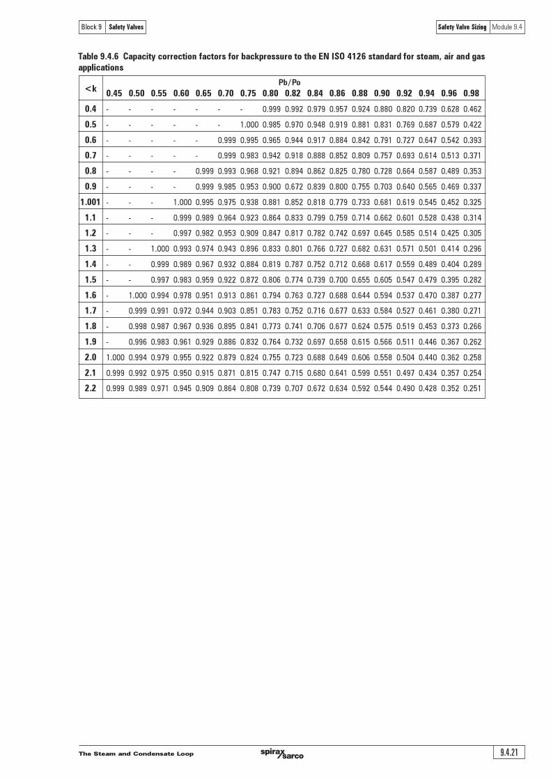
The Steam and Condensate Loop 9.4.21
Block 9 Safety Valves Safety Valve Sizing Module 9.4
Table 9.4.6 Capacity correction factors for backpressure to the EN ISO 4126 standard for steam, air and gas
applications
Pb / Po<k
0.45 0.50 0.55 0.60 0.65 0.70 0.75 0.80 0.82 0.84 0.86 0.88 0.90 0.92 0.94 0.96 0.98
0.4 - - - - - - - 0.999 0.992 0.979 0.957 0.924 0.880 0.820 0.739 0.628 0.462
0.5 - - - - - - 1.000 0.985 0.970 0.948 0.919 0.881 0.831 0.769 0.687 0.579 0.422
0.6 - - - - - 0.999 0.995 0.965 0.944 0.917 0.884 0.842 0.791 0.727 0.647 0.542 0.393
0.7 - - - - - 0.999 0.983 0.942 0.918 0.888 0.852 0.809 0.757 0.693 0.614 0.513 0.371
0.8 - - - - 0.999 0.993 0.968 0.921 0.894 0.862 0.825 0.780 0.728 0.664 0.587 0.489 0.353
0.9 - - - - 0.999 9.985 0.953 0.900 0.672 0.839 0.800 0.755 0.703 0.640 0.565 0.469 0.337
1.001 - - - 1.000 0.995 0.975 0.938 0.881 0.852 0.818 0.779 0.733 0.681 0.619 0.545 0.452 0.325
1.1 - - - 0.999 0.989 0.964 0.923 0.864 0.833 0.799 0.759 0.714 0.662 0.601 0.528 0.438 0.314
1.2 - - - 0.997 0.982 0.953 0.909 0.847 0.817 0.782 0.742 0.697 0.645 0.585 0.514 0.425 0.305
1.3 - - 1.000 0.993 0.974 0.943 0.896 0.833 0.801 0.766 0.727 0.682 0.631 0.571 0.501 0.414 0.296
1.4 - - 0.999 0.989 0.967 0.932 0.884 0.819 0.787 0.752 0.712 0.668 0.617 0.559 0.489 0.404 0.289
1.5 - - 0.997 0.983 0.959 0.922 0.872 0.806 0.774 0.739 0.700 0.655 0.605 0.547 0.479 0.395 0.282
1.6 - 1.000 0.994 0.978 0.951 0.913 0.861 0.794 0.763 0.727 0.688 0.644 0.594 0.537 0.470 0.387 0.277
1.7 - 0.999 0.991 0.972 0.944 0.903 0.851 0.783 0.752 0.716 0.677 0.633 0.584 0.527 0.461 0.380 0.271
1.8 - 0.998 0.987 0.967 0.936 0.895 0.841 0.773 0.741 0.706 0.677 0.624 0.575 0.519 0.453 0.373 0.266
1.9 - 0.996 0.983 0.961 0.929 0.886 0.832 0.764 0.732 0.697 0.658 0.615 0.566 0.511 0.446 0.367 0.262
2.0 1.000 0.994 0.979 0.955 0.922 0.879 0.824 0.755 0.723 0.688 0.649 0.606 0.558 0.504 0.440 0.362 0.258
2.1 0.999 0.992 0.975 0.950 0.915 0.871 0.815 0.747 0.715 0.680 0.641 0.599 0.551 0.497 0.434 0.357 0.254
2.2 0.999 0.989 0.971 0.945 0.909 0.864 0.808 0.739 0.707 0.672 0.634 0.592 0.544 0.490 0.428 0.352 0.251
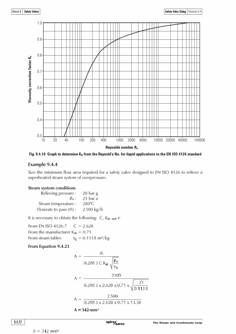
The Steam and Condensate Loop9.4.22
Block 9 Safety Valves Safety Valve Sizing Module 9.4
Example 9.4.4
Size the minimum flow area required for a safety valve designed to EN ISO 4126 to relieve asuperheated steam system of overpressure.
Steam system conditionsRelieving pressure : 20 bar g
ro : 21 bar aSteam temperature : 280°C
Flowrate to pass (m) : 2500 kg /h
It is necessary to obtain the following: C, Kdr and n
From EN ISO 4126:7 C = 2.628
From the manufacturer Kdr = 0.71
From steam tables ng = 0.1138 m³ /kg
From Equation 9.4.23
!"!
#$%&& '!(!) !
%*##
!"!
%+
#$%&& '!,!%$-%&!,!#$.+!,!
#$++' &
%*##
!"!
#$%&& '!,!%$-%&!,!#$.+!,!+'$*&
ν
!"
#
!"!#$%!&&'
!"!#$%!&&
1.0
0.9
0.8
0.7
0.6
0.5
0.4
0.310 20 40 40000100 200 400 1000 2000 4000 10000 20000 100000
Fig. 9.4.10 Graph to determine Kv from the Reynold�s No. for liquid applications to the EN ISO 4126 standard
Reynolds number Re
Vis
co
sity
co
rre
cti
on
fa
cto
r Kv

The Steam and Condensate Loop 9.4.23
Block 9 Safety Valves Safety Valve Sizing Module 9.4
Appendix A - Properties of industrial liquids
Table 9.4.7 Properties of some common industrial liquids
For specific gravity (G) used in ASME liquid sizing calculations, divide density by 998 (density of water).
Boiling point (°C)Liquid Chemical formula
at 1.013 bar aDensity (kg / m³)
Acetone CH2.CO.CH
356.0 791
Ammonia NH3
- 33.4 609
Benzene C6H6
80.0 879
Butalene C4H8
- 6.3 600
Butane C4H10
- 0.5 580
Carbon disulphide CS2
46.0 1 260
Carbon tetrachloride CCl4
76.7 1 594
20% caustic soda NaOH 1 220
Crude oil 700 to 1 040
Diesel oil 175.0 880
Ethanol C2H5OH 78.0 789
Freon 12 CF2Cl2
- 29.8 1 330
Glycol C2H4(OH)
2197.5 1 140
Light fuel oil 175.0 850
Heavy fuel oil 220.0 to 350.0 950
Kerosene 150.0 to 300.0 740
Methanol C3OH 65.0 792
Naphthalene C10
H8
218.0 1 145
Nitric acid HNO3
86.0 1 560
Propane C3H8
- 42.0 500
Sulphurous acid H2SO3
338.0 1 400
Toluene C6H5.CH3
111.0 867
Trichlorethylene CHCl.CCl2
87.0 1 464
Water H2O 100.0 998

The Steam and Condensate Loop9.4.24
Block 9 Safety Valves Safety Valve Sizing Module 9.4
Properties of industrial gases
Table 9.4.8 Properties of some common industrial gases
For specific gravity (G) used in ASME gas sizing calculations, divide molar mass by 28.96 (molar mass of air).
Molar Isentropic Specific volume (V)
Gas Chemical mass (M) coefficient (k) m³ / kg at
formula kg / kmol at 1.013 bar a 1.013 bar a
and 0°C � and 0°C
Acetylene C2H2
26.02 1.26 0.853
Air 28.96 1.40 0.773
Ammonia NH3
17.03 1.31 1.297
Argon Ar 39.91 1.66 0.561
Benzene C6H6
78.00 1.10
Biphenyl oxide C12
H10
166.00 1.05* 0.0094*
Butane - n C4H10
58.08 1.11 0.370
Butylene C4H8
56.10 1.20
Carbon disulphide 76.00 1.21
Carbon dioxide CO2
44.00 1.30 0.506
Carbon monoxide CO 28.00 1.40 0.800
Chlorine Cl2
70.91 1.35 0.311
Cyclohexane 84.00 1.08
Ethane C2H6
30.05 1.22 0.737
Ethylene C2H4
28.03 1.25 0.794
Freon 12 Cf2Cl2
121.00 1.14
Helium He 4.00 1.66
Hexane C6H14
86.00 1.08
Hydrogen H2
2.02 1.41 11.124
Hydrogen chloride HCl 36.46 1.40 0.610
Hydrogen sulphide H2S 34.08 1.32 0.651
Isobutane CH(CH3)3
58.05 1.11 0.375
Methane CH4
16.03 1.31 1.395
Methyl chloride CH3Cl 50.48 1.28 0.434
Natural gas 19.00 1.27
Nitrogen N2
28.02 1.40 0.799
Nitrous oxide N2O 44.02 1.30 0.746
Oxygen O2
32.00 1.40 0.700
Pentane C5H12
72.00 1.09 0.451
Propane C3H8
44.06 1.13 0.498
Sulphur dioxide SO2
64.07 1.29 0.342
Dry saturated steam H2O 18.015 1.135 �
Superheated steam H2O 18.015 1.30 �
� These are typical values, not values at 1.013 bar and 0°C
* At 15°C
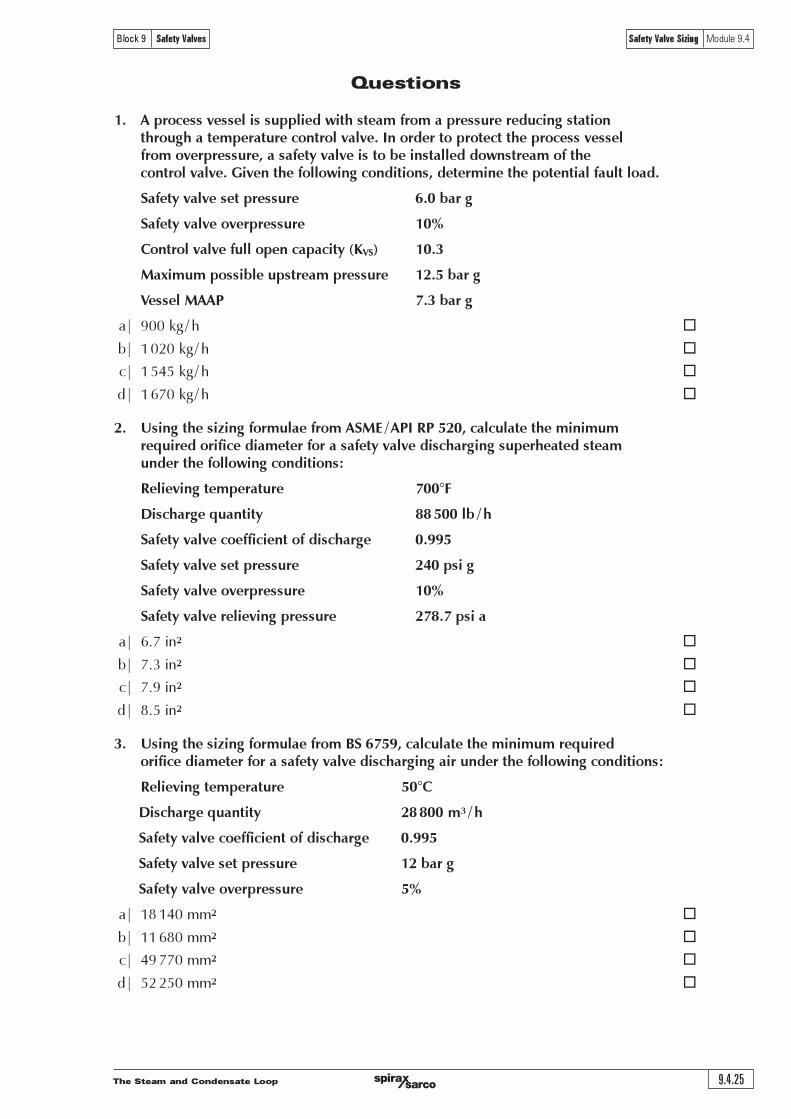
The Steam and Condensate Loop 9.4.25
Block 9 Safety Valves Safety Valve Sizing Module 9.4
Questions
1. A process vessel is supplied with steam from a pressure reducing stationthrough a temperature control valve. In order to protect the process vesselfrom overpressure, a safety valve is to be installed downstream of thecontrol valve. Given the following conditions, determine the potential fault load.
Safety valve set pressure 6.0 bar g
Safety valve overpressure 10%
Control valve full open capacity (KVS) 10.3
Maximum possible upstream pressure 12.5 bar g
Vessel MAAP 7.3 bar g
a| 900 kg / h ¨
b| 1020 kg / h ¨
c| 1545 kg / h ¨
d| 1670 kg / h ¨
2. Using the sizing formulae from ASME / API RP 520, calculate the minimumrequired orifice diameter for a safety valve discharging superheated steamunder the following conditions:
Relieving temperature 700°F
Discharge quantity 88 500 lb / h
Safety valve coefficient of discharge 0.995
Safety valve set pressure 240 psi g
Safety valve overpressure 10%
Safety valve relieving pressure 278.7 psi a
a| 6.7 in2 ¨
b| 7.3 in2 ¨
c| 7.9 in2 ¨
d| 8.5 in2 ¨
3. Using the sizing formulae from BS 6759, calculate the minimum requiredorifice diameter for a safety valve discharging air under the following conditions:
Relieving temperature 50°C
Discharge quantity 28 800 m3 / h
Safety valve coefficient of discharge 0.995
Safety valve set pressure 12 bar g
Safety valve overpressure 5%
a| 18 140 mm2 ¨
b| 11 680 mm2 ¨
c| 49 770 mm2 ¨
d| 52 250 mm2 ¨
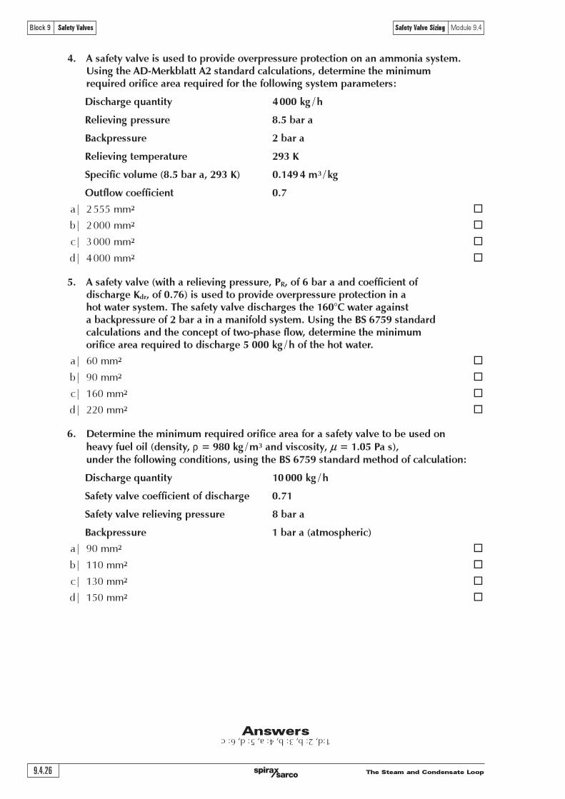
The Steam and Condensate Loop9.4.26
Block 9 Safety Valves Safety Valve Sizing Module 9.4
Answers 1:d, 2: b, 3: b, 4: a, 5: d, 6: c4. A safety valve is used to provide overpressure protection on an ammonia system.
Using the AD-Merkblatt A2 standard calculations, determine the minimumrequired orifice area required for the following system parameters:
Discharge quantity 4 000 kg / h
Relieving pressure 8.5 bar a
Backpressure 2 bar a
Relieving temperature 293 K
Specific volume (8.5 bar a, 293 K) 0.149 4 m3 / kg
Outflow coefficient 0.7
a| 2 555 mm2 ¨
b| 2 000 mm2 ¨
c| 3 000 mm2 ¨
d| 4 000 mm2 ¨
5. A safety valve (with a relieving pressure, PR, of 6 bar a and coefficient ofdischarge Kdr, of 0.76) is used to provide overpressure protection in ahot water system. The safety valve discharges the 160°C water againsta backpressure of 2 bar a in a manifold system. Using the BS 6759 standardcalculations and the concept of two-phase flow, determine the minimumorifice area required to discharge 5 000 kg / h of the hot water.
a| 60 mm2 ¨
b| 90 mm2 ¨
c| 160 mm2 ¨
d| 220 mm2 ¨
6. Determine the minimum required orifice area for a safety valve to be used onheavy fuel oil (density, r = 980 kg / m3 and viscosity, m = 1.05 Pa s),under the following conditions, using the BS 6759 standard method of calculation:
Discharge quantity 10 000 kg / h
Safety valve coefficient of discharge 0.71
Safety valve relieving pressure 8 bar a
Backpressure 1 bar a (atmospheric)
a| 90 mm2 ¨
b| 110 mm2 ¨
c| 130 mm2 ¨
d| 150 mm2 ¨

����������������������������� �����
������� ������������� ������������� !�������"#! ����������
�����������������������������������
������������������������� �!"#$%&'�())*�+!$#,-.+,#���/$0$'12
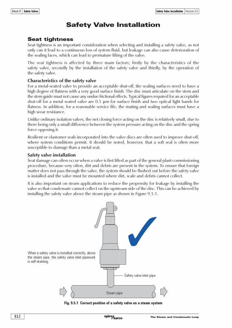
����������������������������������
������� ������������� ������������� !�������"#! ����������
�������������������������
�������������������������������������������������������������������������������������������������������������������������������������������������������������������������������������������������������������������������������������������������������������������������������������
���� ����� ���������� ��� ��������� ��� ����������� ��������� �������� ��� ���� ���������������� ��� ���������� ������� ������������ ���� ���������������� ���� ������� ������ ���� ��������� ��� ���������������������������������
����������������������������������� ����������!������������������������������������������!�����������������������������������������������������������������������������������������������������������������������������������������������������������������������������������������������������������������������"���������������������������!���������������������������������#�$����������������������������������������������������������������%�����������������������������������������������������������������������������������������������������������
&������������������������������������������������������������������������������������������������������������������������������������������������������������������������������������������������������������������������
'��������������������������������������������������������������������������������������������!���������� �������������������������� %�� �������������������������� ������� ����� ����� �����������������������������������������������������
�������������!���������!������������������������������������������������������������������������������������������������������������������������������������������������������������������������������������������������������������������������������������������������������������������������������������������������������������������������������������������������������������������������������������������
%�������������������������������������������������������������������������������������������������������������������������������������������������������������������������������������������������������������������������������������������������������������� ������(�$�)�
����������������������������������������������������������������
�����������������������
�����������������������������������������������������������������������������������������������������������������
�
����������

����������������������������� �����
������� ������������� ������������� !�������"#! ����������
������������������������������������������������������������������ ������ ����������� ������ ����������� ������������ ������������������ ������� ������� ���� ��������� �������� ��������� ��� ���������� ���������� ���� �����������������������������������������������������������������������������������������������������������������������
���������������������������������������������������������������������������������������������������������������������������������������������������������������������������������������������������������������������������������������������������
��������������������������������������������������������������������������������������������������������������������������������������������������������������������� °µ�¾ÀÉ����������������������������������������������������������������������
Ì�������������������������������������������������������������������������������������������������������������������������������������������� ��������������������������������������������������������������Ñ�¾�À������������������������
������������������������������������������������������������������
��������� ��!�������������������������������������������������������
����������
�������������������������������������������������������������������������������������������������������������������� ����������������������������������������������!���������������������������������Ñ�¾�"�
����������
!���"�!��#�$�%$���"��&"��%%�'(�%)*� �+�� "����� ����,"�����-�&�-)&'�&"���&'-)%%�-�� )&� �+�� .�"�/���"�'�� )!� �+�� $�%$�� "���0�
1�&��.�*�/'"
2)*��)�&��"��%%�()/��'/��&

����������������������������������
������� ������������� ������������� !�������"#! ����������
�����������������������������������������������������
���������������������������������������������������������������������������������������������������������� ��������������������������������������������������������������������������������!���������������!�����������"��������������������������� �#������������!���������������������������������������������������������������!�����������!�$%�����������������������!��������������������������
&���������������������������������������������������'������������!�������!�����������������(����������������������������������!����)����������������������!���������������'��������������������������������������������������������*+#�,-.
��������������������������������������������������������������������������������������������������������������� ��������� ��� ��������� ��������� �����������&��������� �!!���� �����������������������������������������������������!��(�������!������������!���������������������������� �#!������������������������� �������!� ����� ��������� �������������������!������������ �����������������(��(����������������������������������� ��������������!� ��������!������������������� ��!������������������(���������!�������
/������(�����������������������(������(������������������������������00������������������������������� �1��(� ������������ ����� ������������ �������� ���������� ���� ������ ���� ��������������"���!�����������"�����������������( �2�������� ��� ��� ���������������������0���!���������!������������������)����(��������������������������������������������������������������!!���������������������'�����(��!!��������������������
#������������������!��������������������������������(�������������������������(������������������������������������������������������������������������"�!!��!������!����
#������������!�����������������������������(����������3����������������(����456�������������7����������������������������������(
#!�#�����������*�������(�*�����������������������������������������������(���������������������������������������!�������6���������������� �����*819��������������������������������������������������(�����������(� ����:��������;��������� ��� �����'�����(����������������(��� 4<=6������������������������������������������������
���������������������������
� �!"#$%���&
'()���*������(������(�+(���+���,�-���,�
���!��.��+()���*�����/.(�������-������0��.��/����������)�+���(������)���(�1�*��//�������+�/�(-� �++�������� *(**��,� (-� �.�� /�-��1� )��)�$
2�1�*(��������/�+(����1���3�,��*��.��(������(+3��
&�������������!��������������������������������������������������������������������������(�����������������������������������������������>%?��!�������������������������3�����������> , @7 �&����������!� ������!��(������� ������������������A���������������������������� ���������!������� �������$- .�����������������!�����!�������������������������������������������������� �&�����������!�������� ����������� !���� ����� ����� ���� ������� ��� �������� � ���� ���� ��B����(� �!� ������� ���������.%�����������������������������������-%�������������������
����/*������)�//��
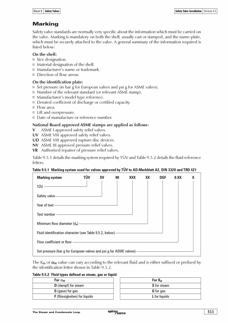
����������������������������� �����
������� ������������� ������������� !�������"#! ����������
�������
����������������������������������������������������������������������������������������������������������������������������������������������������������������������������������������������������������������������������������������������������������������������������������������������������������
�������������� �� ��������������� ����������������������������������� ������������!��������������������� "�����������������������
������� !��� " #$� %��&�$���� �������������#�������������$��������������������������������$�������%�� &�������������������������������#���������������$������%�� ������������!������������������������ "������������������������������������������������������� '���������� (���������������������� "���������������������������������������
'$� %�$��(%$)!�$&&)%*�!�+,-.���$/&��$)��$&&� �!�$��"%��%0��1 ���$�)�������������������������������21 ���$�*)))�������������������������������23 ���$�*)))�������������������������������'1 ���$�)))���������������������������������14 ����������������������������������������������
+�����,�-�.����������������������������������������+/*�����+�����,�-�0������������������������������������
��������������������������������������������������������������������������������� °�µµ�¾������À��É��
�������������� ��� Ì� �Ñ ÒÒÒ ÒÒ �ÓÔ ¾�ÒÒ Ò
���
������������
������������
�����������
�������������������������
!�������������"������"#���"���������������$%&%'(������
!����"�����"������������
����)�������������*�����+���)���������������)���*�����,��+�������
�������� !�� �"#$%��&#'�"#!(�#&& !)*'+�, �,���!�$�"#',�-$%*)�#')�*.��*,��!�.%--*/�)� !�0!�-*/�)�1(,���*)�',*-*&#,* '�$�,,�!�.� 2'�*'��#1$��345464
��������������������������������������������������������
����� ���� !"
!�����)� ���������� "����������
#��*��� �����*�� #�����*��
�����-���*.����� �������/���� $�������/����
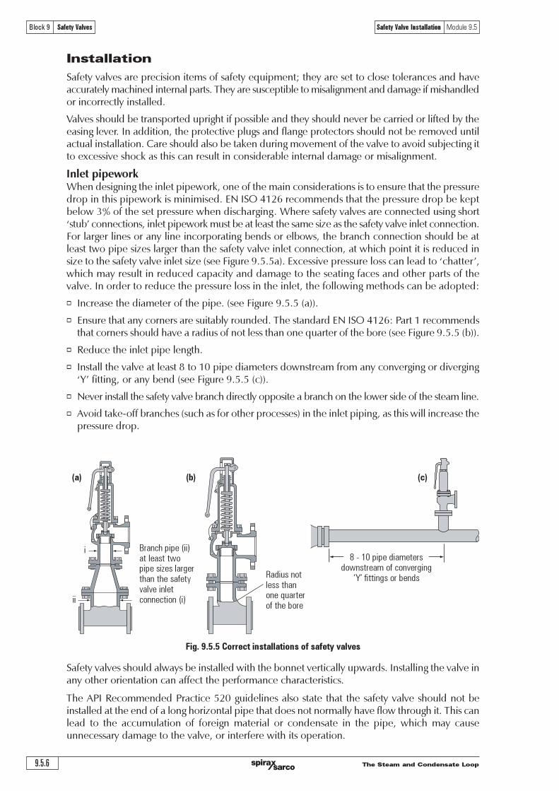
����������������������������������
������� ������������� ������������� !�������"#! ����������
������������
��������������������������������������������������������������������������������������������������������������������������������������������������������������������������������������������������������������������������
�������������������������������������������������������������������������������������������������������������������������������������������������������������������������������������������������������������������������������������������������������������������������������������������������������������������������������������������������������������������������������������������
�������������� ����������������������������!�����������������������������������������������������������������������������������!������������������"#���$�%&'(����������������������������������������������!�)*���������������������!����������������� ��������������������������������������������+����,������������������������!��������������������������������-���������������������������������������.�������������������������������������������������������!��������������������������������������������!���������-�����������������������������������������������������!�����������������������������-������������������������������-��/����.������0�1�1�2��"�����������������������������������+�������,�!�������������������������������������������������������������������������������������������������������������������������������������������������������������!��������������������������3
� �����������������������������������/����.������0�1�1�/�22�
� "����������������������������������������������������������"#���$�%&'(3�4����&��������������������������������������������������������������������������������������/����.������0�1�1�/�22�
� 5����������������������������
� ���������������������������6����&7������������������!����������������������������������������+8,����������������������/����.������0�1�1�/�22�
� #�������������������������������������������������������������������������!��������������������������
� 9���������:�������������/���������������������������2������������������������������!������������������������������
�����������������������!�����������������!����������������������������!����������������������������������������������������������������������������������������������
����94��5�����������4��������1'7���������������������������������������������������������������������������������������������-������������������������������������������!�������������������������� ��� ���� ������������� ��� ����������������� ��� ����������� ��� ���� ������!��������� ���������������������������������������������������!������������������
�������������������������������������������������
�! "! �!
�
��
�������������������������������������������������������������������������������������
�����������������������������������������
�!�"#���������$��������������$��������������
%&'������������������

����������������������������� �����
������� ������������� ������������� !�������"#! ����������
��������������
������ ! "#$�% #&'�(��%)''*+�! ,-.#/&0�1(%0�12(�%34%$#$�%)'*�! 5#67�&�2�%7&$&7#(8%)92%:%�*" ! ;&4�(8%/&0/�%6�(%$��66.��%)<&�%2*%%=%%>?@/ ! ;$�7#4#7%/30.'�%34%6&(.�&(� %6(�&'%&(%(��%$��66.��%)"*%)'!%:%92*
A��%$��66.��% )"*% 6�3.0 %<�% (&9�1%&6% (��%'&=#'.'%&003B&<0�%$��66.��% �3$%&773� #12% (3% (����0�/&1(%6(&1 &� ?%C1%(��%7&6�%34%,D%C;E%F@GH�%"&�(%@I%(�#6%B3.0 %<�%@>J%34%(��%6�(%$��66.��%&1 #(%#6%&(%(�#6%$��66.��%/ %#6%(&9�1?
� �!"#$������K&07.0&(�%(��%13'#1&0% #&'�(��%34%(��% #67�&�2�%$#$�B3�9%43�%&%6&4�(8%/&0/�%��-.#�� %(3% #67�&�2�@%>>>%92%:%�%34%6&(.�&(� %6(�&'L%2#/�1%(�&(%(��%6(�&'%#6%(3%<�% #67�&�2� %#1(3%&%/�1(� %(&19%/#&(��%$#$�B3�9I%B�#7�%�&6%&1%�-.#/&0�1(%0�12(�%34%GM%'?%A��%6�(%$��66.��%34%(��%6&4�(8%/&0/�%#6@>%<&�%2%&1 %(��%&77�$(&<0�%<&79$��66.��%#6%@>J%34%(��%6�(%$��66.��?%)N66.'�%O��3%$��66.��% �3$&0312%(��%(&19%/�1(*?
%�&'$()%C4%(��%'&=#'.'%@>J%<&79$��66.��%#6%&003B� I%(��1%(��%2&.2�%$��66.��%&(%(��%6&4�(8/&0/�%3.(0�(%B#00%<��
P6#12% 6&(.�&(� % 6(�&'% (&<0�6I% (��% 6$�7#4#7% /30.'�% &(% (�#6% $��66.��% #6I% / %!% >?QQ%'! % :%92?
N$$08#12%,-.&(#31%R?M?@�
A����43��I% (��%$#$�B3�9%7311�7(� % (3% (��%3.(0�(%34% (��% 6&4�(8%/&0/�% 6�3.0 %�&/�%&1% #1(��1&0 #&'�(��%34%&(%0�&6(%MF%''?%�#(�%67�� .0�%F>%$#$�I%(�#6%B3.0 %��-.#��%&%5DHM%$#$�?
�
���������������A����%&��%(B3%$366#<0�%(8$�6%34% #67�&�2�%686(�'%S%3$�1%&1 %7036� ?%N1%3$�1%686(�'% #67�&�2�6 #��7(08%#1(3%(��%&('36$����%B����&6%&%7036� %686(�'% #67�&�2�6%#1(3%&%'&1#430 %&0312%B#(�%3(���6&4�(8%/&0/�6?
C(%#6%��73''�1 � %(�&(% #67�&�2�%$#$�B3�9%6�3.0 %�#6�%43�%6(�&'%&1 %2&6%686(�'6I%B����&6%43�0#-.# 6I%#(%6�3.0 %4&00?%T3�#O31(&0%$#$�B3�9%6�3.0 %�&/�%&% 3B1B&� %2�& #�1(%34%&(%0�&6(%@%#1%@>>&B&8%4�3'%(��%/&0/�%�16.�#12%(�&(%&18% #67�&�2�%B#00%<�%6�04U �#12?%C(%#6%#'$3�(&1(%(3% �%&18�#6#12% #67�&�2�%$#$�B3�9?%V��(#7&0%�#6�6%B#00%��-.#��%6�$&�&(�% �&2�?%D3(��%&00%$3#1(6%34%686(�' �&2�%&��%6.<W�7(%(3%(��%6&'�%$��7&.(#316I%13(&<08%(�&(%/&0/�%$��43�'&17�%'.6(%13(%<�%&44�7(� I&1 %&18%40.# %'.6(%<�% #67�&�2� %(3%&%6&4�%037&(#31?
C(%#6%�66�1(#&0%(3%�16.��%(�&(%40.# %7&113(%7300�7(%31%(��% 3B16(��&'%6# �%34%&%6&4�(8%/&0/�I%&6%(�#6B#00% #'$&#�% #(6%$��43�'&17�%&1 %7&.6�%73��36#31%34%(��%6$�#12%&1 %#1(��1&0%$&�(6?%X&18%6&4�(8/&0/�6%&��%$�3/# � %B#(�%&%<3 8% �%7311�7(#31I%#4%(�#6%#6%13(%.6� %3�%13(%$�3/# � I%(��1%&%6'&00<3��% �%6�3.0 %<�%4#((� %#1%7036�%$�3=#'#(8%(3%(��%/&0/�%3.(0�(%)6��%Y#2.��%R?M?Z*?
E1�%34%(��%'%7317��16%#1%7036� %686(�'6%#6%(��%$��66.��% �3$%3�%<.#0(U.$%<&79$��66.��%#1%(�� #67�&�2�%686(�'?%N6%'�1(#31� %#1%X3 .0�%R?GI%(�#6%7&1% �&6(#7&008%&44�7(%(��%$��43�'&17�%34%&6&4�(8%/&0/�?%A��%,D%C;E%F@GH�%"&�(%@%6(&1 &� %6(&(�6%(�&(%(��%$��66.��% �3$%6�3.0 %<�%'(� <�03B%@>J%34%(��%6�(%$��66.��?%C1%3� ��%(3%&7�#�/�%(�#6I%(��% #67�&�2�%$#$�%7&1%<�%6#O� %.6#12,-.&(#31%R?M?@?
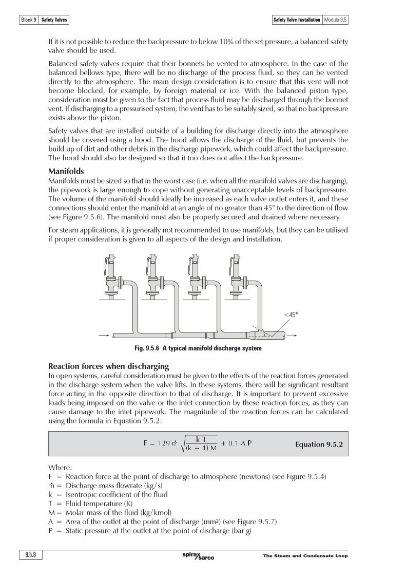
����������������������������������
������� ������������� ������������� !�������"#! ����������
�����������������������������������������������
��������������
���
���������������������������������������������������������������������������������������������������� �� ����������������!
"��������������� �� �����#��������������������������� �����������$�������!������������������������������������������������������������������%��������������������������������������� �����������������������$�������!�&���$��������%��������������������������������������� ����������������$�� ��������� ���� �'�$����� ��� �����%��$�������� ��� ���!�(���� ���� ��������� ������� �������������������$�������%� ����������������������������������$�������������%��������%������������ ���!�����������%��%�����������������������$������ �������������������������)����������������������������'�������� ������������!
*������ �� ������������������������������������������%������������%����������������������$������������������� ���������%�������!�&��������������������������%����������������������� ��������������������������������������������������������%�����������������������������������������������!&���������������������������%���������������������������������������������������!
���������+���������$���������)�����������������������������,�!�!��������������$�������� �� ��������������%��%-��������������������%������%������������������%��������%���������������� �������������������!&��� ���$���������$�������������������������������������������� �� ����������������������������������������������������������$����������������%���������%������������./ �������������������������,����0�%����1!/!2-!�&���$��������$��������������������������������������������������������!
0�������$���������������������%�����������������$$�������������$�������������������������������������������������������������%� �����������������������������%������������������!
!�"#���$��%"!�$&'!�$���"'�%(��(�������������$�������������������������$�������%� �����������������������������������������%����������������������%�������$���������� �� �������!���������������$�������������������%�����������������������������%���������������������������������������������%�!��������$�������������� �����'����� �����������%��$������������� �� �����������������������������������������������������������������������$�%�����������������������!�&���$�%���������������������������������������������������%��������$�������3#�������1!/!45
(����50 6 7�������������������������������������%�������$��������,�������-�,����0�%����1!/!.-�6 8������%��$�������������,�%�9��-� 6 �����������������������������������& 6 0�������$���������,:-+6 +�����$�����������������,�%�9��$��-; 6 ;�����������������������������������������%��,$$�-�,����0�%����1!/!<-= 6 *����������������������������������������������������%��,����%-
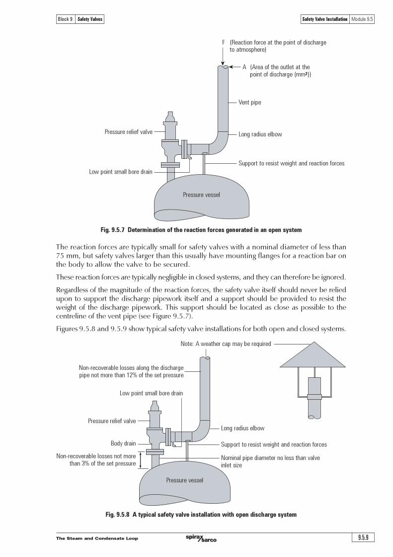
����������������������������� �����
������� ������������� ������������� !�������"#! ����������
����������������������������������������������������������������������������
��������� ��!�������"��������#�"#�������""������$�������������������������
� �������������������������� �!"�����#!$%���&���''�((
) �*��%�!�"����%��������� �!"�����#!$%���&������'�$ ����(
+��$$�������!���,��,� -�"&���#!�$���.�/
0� ���������$!$��/�!&����"#����%�!�"����%�$
+��$$����,�$$��
1�"�� ! �
2���3���/�������%� �'�4�.����5�!��#
+��$$�������!���,��,�
6�#4�#��!"
-�/� �!"��$'����.����#��!"
2�"7��%�,���.�����$$�$�"���'������"�89��������$��� ��$$���
-�"&���#!�$���.�/
0� ���������$!$��/�!&����"#����%�!�"����%�$
2�'!"��� ! ��#!�'�����"����$$����"�,��,�!"����$!:�
+��$$����,�$$��
���������������������������������������������������������������������������������������������� !���"�#$�������������������%�������������$�$������������$����%�����%������������������#���������#��������������������������#�����$���&
��������������������������������������%��%�#��������������������"������������������������#���%�����&
'�%�����������������%���$�������������������������"����������������������������$���������#��������$��������$�����������������%���������(���������������$���������$���#���������������������������%������ �����������%���������(&�������$���������$���#���������������������������#�������������������������������������)����*�%$���+&!& ,&
*�%$����+&!&-�����+&!&+���������������������������������������������#���������������������������&
�
�
2�"7��%�,���.�����$$�$����"&�����#!$%���&� ! ��"���'�������"�;<9��������$��� ��$$���
-�/� �!"��$'����.����#��!"
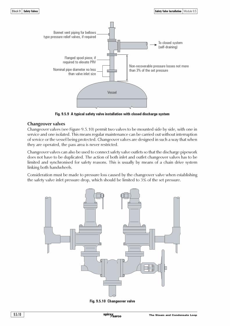
�����������������������������������
������� ������������� ������������� !�������"#! ����������
����������������������������������������������������������������������������
��������� !��"���������������
������������������������������� ��������!�����������"����#������$!���%
&��'����%�� ���()����*%�"�����+
,�"���%����������'�#�����$!���%��������"���-./
0�(��"�������%�"(�������������1"���"������������2�
0��*��'����"���������!��������������(����1"��34�����1�����������!��
/�����
���������������������������������������������������������������������������������������������������������������������������������������������������������������������������������������������������������������������������������������������������������������������������������������������������������������������������������������������������������������������
������������������������������������������������������������������������������������������������ ������������������������������������������������������������������������������������������������������������������������������������������������� ���������������������������������������������� ��������������������
�������������������������������������������������������������������������������������������������������������������������������������������������������������°µ���������������������
�
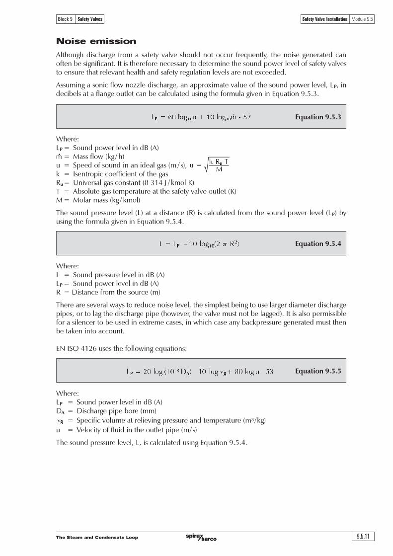
����������������������������� ������
������� ������������� ������������� !�������"#! ����������
������ �! "#$%&'(#)��'*�+�*',%'&-'./0�! 1233'4*#)'.56'7'�0$ ! "(��&'#4'3#$%&',%'2%',&�2*'623'.8'7'3095 ! :3�%;�#(,<'<#�44,<,�%;'#4';��'623= ! >%,+��32*'623'<#%3;2%;'.?'@AB'C'7'58#*'D0E ! /F3#*$;�'623';�8(��2;$��'2;';��'324�;G'+2*+�'#$;*�;'.D01! 1#*2�'8233'.56'7'58#*0
E��'3#$%&'(��33$��'*�+�*'. 0'2;'2'&,3;2%<�'.=0',3'<2*<$*2;�&'4�#8';��'3#$%&'(#)��'*�+�*'. �0'FG$3,%6';��'4#�8$*2'6,+�%',%'HI$2;,#%'JKLKBK
��������������
�������������
��������������
/*;�#$6�'&,3<�2�6�' 4�#8'2'324�;G'+2*+�'3�#$*&'%#;'#<<$�' 4��I$�%;*G9' ;��'%#,3�'6�%��2;�&'<2%#4;�%'F�'3,6%,4,<2%;K':;',3';����4#��'%�<�332�G';#'&�;��8,%�';��'3#$%&'(#)��'*�+�*'#4'324�;G'+2*+�3;#'�%3$��';�2;'��*�+2%;'��2*;�'2%&'324�;G'��6$*2;,#%'*�+�*3'2��'%#;'�M<��&�&K
/33$8,%6'2'3#%,<'4*#)'%#NN*�'&,3<�2�6�9'2%'2((�#M,82;�'+2*$�'#4';��'3#$%&'(#)��'*�+�*9' �9',%&�<,F�*3'2;'2'4*2%6�'#$;*�;'<2%'F�'<2*<$*2;�&'$3,%6';��'4#�8$*2'6,+�%',%'HI$2;,#%'JKLK@K
������ ! "#$%&'(��33$��'*�+�*',%'&-'./0 �! "#$%&'(#)��'*�+�*',%'&-'./0= !'O,3;2%<�'4�#8';��'3#$�<�'.80
E����'2��'3�+��2*')2G3';#'��&$<�'%#,3�'*�+�*9';��'3,8(*�3;'F�,%6';#'$3�'*2�6��'&,28�;��'&,3<�2�6�(,(�39'#�';#'*26';��'&,3<�2�6�'(,(�'.�#)�+��9';��'+2*+�'8$3;'%#;'F�'*266�&0K':;',3'2*3#'(��8,33,F*�4#�'2'3,*�%<��';#'F�'$3�&',%'�M;��8�'<23�39',%')�,<�'<23�'2%G'F2<5(��33$��'6�%��2;�&'8$3;';��%F�';25�%',%;#'2<<#$%;K
HP':"Q'BARS'$3�3';��'4#**#),%6'�I$2;,#%3�
��������������
������ � ! "#$%&'(#)��'*�+�*',%'&-'./0O! ! O,3<�2�6�'(,(�'F#��'.880
! "(�<,4,<'+#*$8�'2;'��*,�+,%6'(��33$��'2%&';�8(��2;$��'.8" '7'560
$ ! T�*#<,;G'#4'4*$,&',%';��'#$;*�;'(,(�'.8'7'30
E��'3#$%&'(��33$��'*�+�*9' 9',3'<2*<$*2;�&'$3,%6'HI$2;,#%'JKLKBK
�����������������������������������
������� ������������� ������������� !�������"#! ����������
���������
�� ���������������������������������������������������������������������������������������������
�� ������������ �
�� ������������������ �
� !"�������#�$��$#�%#�%���&��� �
%� '�()�&#$�)�����#$����$)�$"�� #�# �$*�)(�$"���#��� �
�� ������������������������������������������������������������������������������������������������������
� ��������������������������������������������
�� ������������������������������������������������������������������������������������
��� ������������������������������������������������������������������������������
#� ��)��* �
�� ���)��* �
� ��#�%��� �
%� �+����#�%���� �
�� ���������������������������������������������������������������� �������!�������������������������������������
� "�����������������������������������������
�� "���������������������������������
��� "�����������������������
#� ��)��* �
�� ���)��* �
� ��#�%��� �
%� �+����#�%���� �
#� $����������������������������������������%&�"'(�#)�*���������������������������������������������+,������������������'��������������������������������������������������������������������������������������-���������������������.�����������)�+,,����/���
#� ,-�&& �
�� .-�&& �
� /.�&& �
%� 0-�&& �

����������������������������� ������
������� ������������� ������������� !�������"#! ����������
������� ����������������������������������� ���������������������������������������������������������������������������������
���������������������������������������������������������������������������������������������������������������������������� °µ���������������������������� ¾���������������À���������������������µ
�� ����� �
� �!��� �
"� �#��� �
$� %&��� �
�� ����������������������������������������������������������������������������������������
�� '(���)*)+,-�./,0,�+/,�)�1,+*�2�32,)�0,4560,�10,45,(+�-�6(+,(�(", �
� '(���)+,�-�)*)+,-�170�./6"/��(*�$7.(+6-,�6)�"7)+3* �
"� 87�,36-6(�+,�$5936"�+6(:�75+3,+�969,.70;�7(���$5�3�)�1,+*�2�32,�)*)+,- �
$� <33�71�+/,�� 72, �

�����������������������������������
������� ������������� ������������� !�������"#! ����������
The Steam and Condensate Loop 9.6.1
Block 9 Safety Valves Alternative Plant Protection Devices and Terminology Module 9.6
Module 9.6Alternative Plant Protection
Devices and Terminology
SC
-GC
M-7
3
CM
Iss
ue 1
©
Copyr
ight
20
05
Spir
ax-S
arco
Lim
ited

The Steam and Condensate Loop9.6.2
Block 9 Safety Valves Alternative Plant Protection Devices and Terminology Module 9.6
Fig. 9.6.2 Typical supplementary loaded safety valves
Fig. 9.6.1 A counterweight safety valve
Alternative Methods of Plant Protection
Although safety valves are by far the most common devices used for plant protection in steamsystems, there are several other devices available to protect plant from overpressure conditions.Whilst some of them can be used in place of a safety valve, most have their own unique applicationsand indeed some devices, such as the bursting disc, may be used to complement the safetyvalve.
o Weighted pallet - This is the simplest type of overpressure protection device, and it is on low-pressure tanks and condensers, for pressure relief, vacuum relief or both.
A weight is applied to the top of a disc, keeping it closed until the pressure acting on theunderside of the pallet equals the weight. Due to the large weights required to keep a palletclosed, this type of valve is designed for low pressure applications below 0.1 bar. For higher setpressures, the weight required would be prohibitive and dangerous if oscillation of the palletoccurred at valve opening.
o Supplementary loaded safety valve - A supplementary loaded safety valve consists ofa conventional safety valve provided with an additional sealing force that is released oncethe set pressure is reached. One ofthe main concerns with this typeof device is ensuring that the loadis suitably released when the setpressure is reached. The BS 6759standard states that even in theevent of the release mechanismfailing , the valve must attainits certified discharge capacitywithin 115% of the set pressure.
Supplementary loaded safetyvalves tend only to be used whereany leakage of the fluid below setpressure is unacceptable, or onvery high pressure systems wheremaintaining a tight shut-off isotherwise difficult.
o Controlled safety pressure relief systems (CSPRS) - These are electric or electropneumaticsystems, which are not self-acting. When an overpressure situation is detected, a control deviceacts to correct the situation.
Counterweight
o Counterweight safety valve -Although these have been largelysuperseded by spring-loaded safetyvalves, they are still sometimesused for low-pressure applications.The closing force of the safety valveis provided by a weight rather thana spring. As the closing force isprovided by a weight, it will remainconstant and once the set pressureis reached, the safety valve willopen fully.
Flow
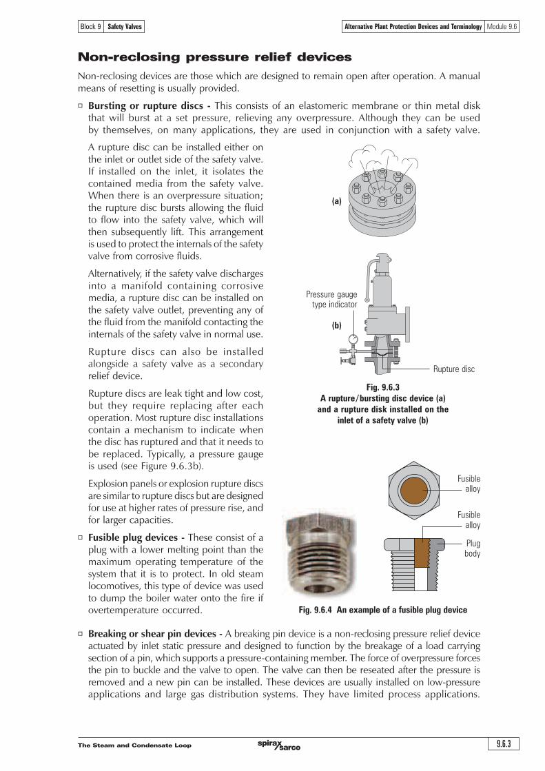
The Steam and Condensate Loop 9.6.3
Block 9 Safety Valves Alternative Plant Protection Devices and Terminology Module 9.6
Non-reclosing pressure relief devices
Non-reclosing devices are those which are designed to remain open after operation. A manualmeans of resetting is usually provided.
o Bursting or rupture discs - This consists of an elastomeric membrane or thin metal diskthat will burst at a set pressure, relieving any overpressure. Although they can be usedby themselves, on many applications, they are used in conjunction with a safety valve.
Fig. 9.6.3
A rupture /bursting disc device (a)
and a rupture disk installed on the
inlet of a safety valve (b)
Pressure gaugetype indicator
Rupture disc
Fusiblealloy
Plugbody
Fusiblealloy
(a)
(b)
Fig. 9.6.4 An example of a fusible plug device
o Breaking or shear pin devices - A breaking pin device is a non-reclosing pressure relief deviceactuated by inlet static pressure and designed to function by the breakage of a load carryingsection of a pin, which supports a pressure-containing member. The force of overpressure forcesthe pin to buckle and the valve to open. The valve can then be reseated after the pressure isremoved and a new pin can be installed. These devices are usually installed on low-pressureapplications and large gas distribution systems. They have limited process applications.
A rupture disc can be installed either onthe inlet or outlet side of the safety valve.If installed on the inlet, it isolates thecontained media from the safety valve.When there is an overpressure situation;the rupture disc bursts allowing the fluidto flow into the safety valve, which willthen subsequently lift. This arrangementis used to protect the internals of the safetyvalve from corrosive fluids.
Alternatively, if the safety valve dischargesinto a manifold containing corrosivemedia, a rupture disc can be installed onthe safety valve outlet, preventing any ofthe fluid from the manifold contacting theinternals of the safety valve in normal use.
Rupture discs can also be installedalongside a safety valve as a secondaryrelief device.
Rupture discs are leak tight and low cost,but they require replacing after eachoperation. Most rupture disc installationscontain a mechanism to indicate whenthe disc has ruptured and that it needs tobe replaced. Typically, a pressure gaugeis used (see Figure 9.6.3b).
Explosion panels or explosion rupture discsare similar to rupture discs but are designedfor use at higher rates of pressure rise, andfor larger capacities.
o Fusible plug devices - These consist of aplug with a lower melting point than themaximum operating temperature of thesystem that it is to protect. In old steamlocomotives, this type of device was usedto dump the boiler water onto the fire ifovertemperature occurred.

The Steam and Condensate Loop9.6.4
Block 9 Safety Valves Alternative Plant Protection Devices and Terminology Module 9.6
Terminology
The following definitions are taken from DIN 3320 but it should be noted that many of the termsand associated definitions used are universal and appear in many other standards. Wherecommonly used terms are not defined in DIN 3320 then ASME / ANSI PTC25.3 has been used asthe source of reference. This list is not exhaustive and is intended as a guide only; it should notbe used in place of the relevant current issue standard:
Operating pressure (working pressure) is the gauge pressure existing at normal operatingconditions within the system to be protected.
Set pressure is the gauge pressure at which under operating conditions direct loaded safetyvalves commence to lift.
Test pressure is the gauge pressure at which under test stand conditions (atmosphericbackpressure) direct loaded safety valves commence to lift.
Opening pressure is the gauge pressure at which the lift is sufficient to discharge thepredetermined flowing capacity. It is equal to the set pressure plus opening pressure difference.
Reseating pressure is the gauge pressure at which the direct loaded safety valve is re-closed.
Built-up backpressure is the gauge pressure built up at the outlet side by blowing.
Superimposed backpressure is the gauge pressure on the outlet side of the closed valve.
Backpressure is the gauge pressure built up on the outlet side during blowing (built-upbackpressure + superimposed backpressure).
Accumulation is the increase in pressure over the maximum allowable working gauge pressureof the system to be protected.
Opening pressure difference is the pressure rise over the set pressure necessary for a lift suitableto permit the predetermined flowing capacity.
Reseating pressure difference is the difference between set pressure and reseating pressure.
Functional pressure difference is the sum of opening pressure difference and reseating pressuredifference.
Operating pressure difference is the pressure difference between set pressure and operatingpressure.
Lift is the travel of the disc away from the closed position.
Commencement of lift (opening) is the first measurable movement of the disc or the perceptionof discharge noise.
Flow area is the cross sectional area upstream or downstream of the body seat calculated fromthe minimum diameter which is used to calculate the flow capacity without any deduction forobstructions.
Flow diameter is the minimum geometrical diameter upstream or downstream of the body seat.
Nominal size designation of a safety valve is the nominal size of the inlet.
Theoretical flowing capacity is the calculated mass flow from an orifice having a cross sectionalarea equal to the flow area of the safety valve without regard to flow losses of the valve.
Actual flowing capacity is the flowing capacity determined by measurement.
Certified flowing capacity is actual flowing capacity reduced by 10%.
Coefficient of discharge is the ratio of actual to the theoretical discharge capacity.
Certified coefficient of discharge is the coefficient of discharge reduced by 10% (also known asderated coefficient of discharge).
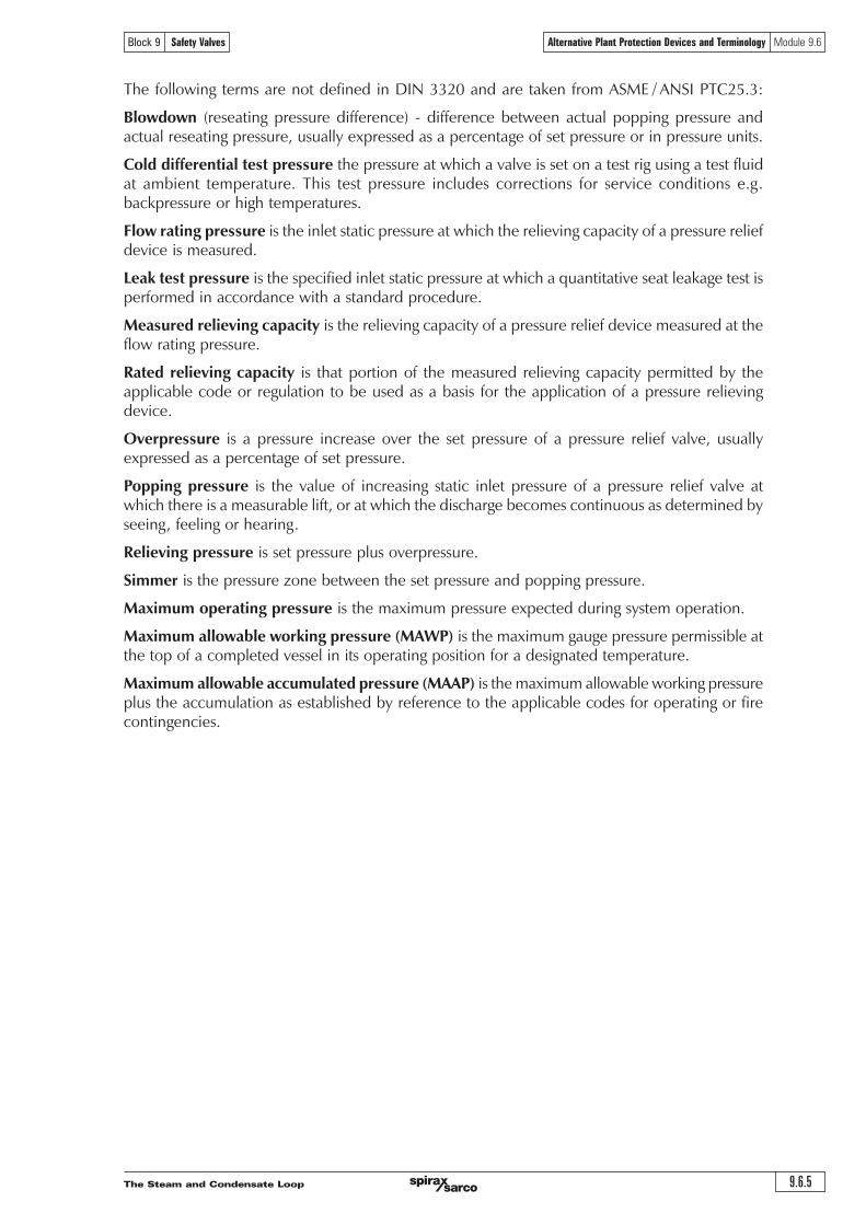
The Steam and Condensate Loop 9.6.5
Block 9 Safety Valves Alternative Plant Protection Devices and Terminology Module 9.6
The following terms are not defined in DIN 3320 and are taken from ASME / ANSI PTC25.3:
Blowdown (reseating pressure difference) - difference between actual popping pressure andactual reseating pressure, usually expressed as a percentage of set pressure or in pressure units.
Cold differential test pressure the pressure at which a valve is set on a test rig using a test fluidat ambient temperature. This test pressure includes corrections for service conditions e.g.backpressure or high temperatures.
Flow rating pressure is the inlet static pressure at which the relieving capacity of a pressure reliefdevice is measured.
Leak test pressure is the specified inlet static pressure at which a quantitative seat leakage test isperformed in accordance with a standard procedure.
Measured relieving capacity is the relieving capacity of a pressure relief device measured at theflow rating pressure.
Rated relieving capacity is that portion of the measured relieving capacity permitted by theapplicable code or regulation to be used as a basis for the application of a pressure relievingdevice.
Overpressure is a pressure increase over the set pressure of a pressure relief valve, usuallyexpressed as a percentage of set pressure.
Popping pressure is the value of increasing static inlet pressure of a pressure relief valve atwhich there is a measurable lift, or at which the discharge becomes continuous as determined byseeing, feeling or hearing.
Relieving pressure is set pressure plus overpressure.
Simmer is the pressure zone between the set pressure and popping pressure.
Maximum operating pressure is the maximum pressure expected during system operation.
Maximum allowable working pressure (MAWP) is the maximum gauge pressure permissible atthe top of a completed vessel in its operating position for a designated temperature.
Maximum allowable accumulated pressure (MAAP) is the maximum allowable working pressureplus the accumulation as established by reference to the applicable codes for operating or firecontingencies.