BlobTree Trees - webhome.cs.uvic.ca
8
BlobTree Trees Callum Galbraith Peter MacMurchy Brian Wyvill Department of Computer Science University of Calgary callum/peterm/[email protected] Abstract In recent years several methods for modeling botanical trees have been proposed. The geometry and topology of tree skeletons can be well described by L-systems; however, there are several approaches to modeling smooth surfaces to represent branches, and not all of the observed phenom- ena can be represented by current methods. Many tree types exhibit non-smooth features such as branch bark ridges and collars. In this research a hierarchical implicit modeling sys- tem is used to produce models of branching structures that capture smooth branching, branch collars and branch bark ridges. The BlobTree provides several techniques to control the combination of primitives, allowing both smooth and non-smooth effects to be intuitively combined in a single blend volume. Irregular effects are implemented using Pre- cise Contact Modeling, Constructive Solid Geometry and space warping. We show that smooth blends can be ob- tained, without noticeable bulging, using summation of dis- tance based implicit surfaces. L-systems are used to create the branching structure allowing botanically based simula- tions to be used as input. 1. Introduction Modeling of branching topologies for botanical struc- tures is a well-studied problem, as is their subsequent vi- sualization. However, generating a realistic and smoothly connected surface around an arbitrary branching skeleton remains difficult. Current methods do not capture the sub- tleties of the blends at branching points, in particular the branch bark ridge [28] and collars, shown in Figure 1. Previous work has focused on the construction of smoothly connected surfaces using parametric, implicit, and subdivision techniques. In this research, a method is pro- posed for the next step in generating realistic models of trees. The approach uses skeletal implicit surfaces in the context of a hierarchical data structure called the Blob- Figure 1. Photographs of poplar trees show- ing: branch bark ridges, rings around branches, branch collar. Tree [31], which combines blending operations with non- blending operations such as Constructive Solid Geome- try (CSG), spacial warping, and Precise Contact Model- ing (PCM) [13]. The method combines PCM and blend- ing to model both smooth blending and the branch bark ridge at branching points as appropriate. Sufficient blend- ing control is demonstrated using summation of distance based skeletal implicit primitives to model smoothly blend- ing branching structures without noticeable bulging. This obviates the need for convolution surfaces, which impose an increase in computational and implementation complex- ity. Non-smooth qualities of trees, such as scars formed where branches have been discarded, are also easily incor-
Transcript of BlobTree Trees - webhome.cs.uvic.ca

BlobTree Trees
Callum Galbraith Peter MacMurchy Brian Wyvill
Department of Computer ScienceUniversity of Calgary
callum/peterm/[email protected]
Abstract
In recent years several methods for modeling botanicaltrees have been proposed. The geometry and topology oftree skeletons can be well described by L-systems; however,there are several approaches to modeling smooth surfacesto represent branches, and not all of the observed phenom-ena can be represented by current methods. Many tree typesexhibit non-smooth features such as branch bark ridges andcollars.
In this research a hierarchical implicit modeling sys-tem is used to produce models of branching structures thatcapture smooth branching, branch collars and branch barkridges. The BlobTree provides several techniques to controlthe combination of primitives, allowing both smooth andnon-smooth effects to be intuitively combined in a singleblend volume. Irregular effects are implemented using Pre-cise Contact Modeling, Constructive Solid Geometry andspace warping. We show that smooth blends can be ob-tained, without noticeable bulging, using summation of dis-tance based implicit surfaces. L-systems are used to createthe branching structure allowing botanically based simula-tions to be used as input.
1. Introduction
Modeling of branching topologies for botanical struc-tures is a well-studied problem, as is their subsequent vi-sualization. However, generating a realistic and smoothlyconnected surface around an arbitrary branching skeletonremains difficult. Current methods do not capture the sub-tleties of the blends at branching points, in particular thebranch bark ridge [28] and collars, shown in Figure 1.
Previous work has focused on the construction ofsmoothly connected surfaces using parametric, implicit, andsubdivision techniques. In this research, a method is pro-posed for the next step in generating realistic models oftrees. The approach uses skeletal implicit surfaces in thecontext of a hierarchical data structure called the Blob-
Figure 1. Photographs of poplar trees show-ing: branch bark ridges, rings aroundbranches, branch collar.
Tree [31], which combines blending operations with non-blending operations such as Constructive Solid Geome-try (CSG), spacial warping, and Precise Contact Model-ing (PCM) [13]. The method combines PCM and blend-ing to model both smooth blending and the branch barkridge at branching points as appropriate. Sufficient blend-ing control is demonstrated using summation of distancebased skeletal implicit primitives to model smoothly blend-ing branching structures without noticeable bulging. Thisobviates the need for convolution surfaces, which imposean increase in computational and implementation complex-ity. Non-smooth qualities of trees, such as scars formedwhere branches have been discarded, are also easily incor-
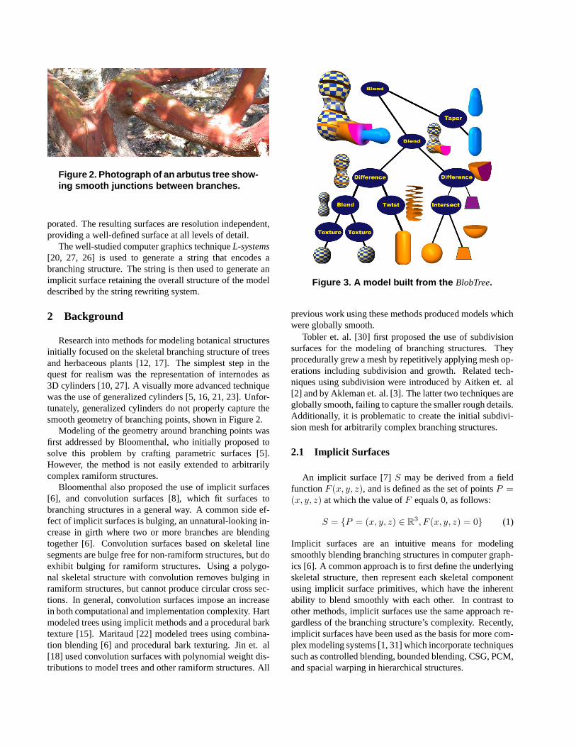
Figure 2. Photograph of an arbutus tree show-ing smooth junctions between branches.
porated. The resulting surfaces are resolution independent,providing a well-defined surface at all levels of detail.
The well-studied computer graphics technique L-systems[20, 27, 26] is used to generate a string that encodes abranching structure. The string is then used to generate animplicit surface retaining the overall structure of the modeldescribed by the string rewriting system.
2 Background
Research into methods for modeling botanical structuresinitially focused on the skeletal branching structure of treesand herbaceous plants [12, 17]. The simplest step in thequest for realism was the representation of internodes as3D cylinders [10, 27]. A visually more advanced techniquewas the use of generalized cylinders [5, 16, 21, 23]. Unfor-tunately, generalized cylinders do not properly capture thesmooth geometry of branching points, shown in Figure 2.
Modeling of the geometry around branching points wasfirst addressed by Bloomenthal, who initially proposed tosolve this problem by crafting parametric surfaces [5].However, the method is not easily extended to arbitrarilycomplex ramiform structures.
Bloomenthal also proposed the use of implicit surfaces[6], and convolution surfaces [8], which fit surfaces tobranching structures in a general way. A common side ef-fect of implicit surfaces is bulging, an unnatural-looking in-crease in girth where two or more branches are blendingtogether [6]. Convolution surfaces based on skeletal linesegments are bulge free for non-ramiform structures, but doexhibit bulging for ramiform structures. Using a polygo-nal skeletal structure with convolution removes bulging inramiform structures, but cannot produce circular cross sec-tions. In general, convolution surfaces impose an increasein both computational and implementation complexity. Hartmodeled trees using implicit methods and a procedural barktexture [15]. Maritaud [22] modeled trees using combina-tion blending [6] and procedural bark texturing. Jin et. al[18] used convolution surfaces with polynomial weight dis-tributions to model trees and other ramiform structures. All
Figure 3. A model built from the BlobTree.
previous work using these methods produced models whichwere globally smooth.
Tobler et. al. [30] first proposed the use of subdivisionsurfaces for the modeling of branching structures. Theyprocedurally grew a mesh by repetitively applying mesh op-erations including subdivision and growth. Related tech-niques using subdivision were introduced by Aitken et. al[2] and by Akleman et. al. [3]. The latter two techniques areglobally smooth, failing to capture the smaller rough details.Additionally, it is problematic to create the initial subdivi-sion mesh for arbitrarily complex branching structures.
2.1 Implicit Surfaces
An implicit surface [7] S may be derived from a fieldfunction F (x, y, z), and is defined as the set of points P =(x, y, z) at which the value of F equals 0, as follows:
S = {P = (x, y, z) ∈ R3, F (x, y, z) = 0} (1)
Implicit surfaces are an intuitive means for modelingsmoothly blending branching structures in computer graph-ics [6]. A common approach is to first define the underlyingskeletal structure, then represent each skeletal componentusing implicit surface primitives, which have the inherentability to blend smoothly with each other. In contrast toother methods, implicit surfaces use the same approach re-gardless of the branching structure’s complexity. Recently,implicit surfaces have been used as the basis for more com-plex modeling systems [1, 31] which incorporate techniquessuch as controlled blending, bounded blending, CSG, PCM,and spacial warping in hierarchical structures.

2.2 The BlobTree
The BlobTree provides a hierarchical data structure forthe definition of complex models based on implicit surfaces.Implicit surface primitives based on distance fields are usedas leaf nodes, while internal nodes consist of operations onarbitrary implicit surfaces (see Figure 3). The BlobTree isan extensible data structure, currently supporting the fol-lowing modeling techniques: CSG, space warping, PCM,2D texture mapping [29], controlled blending [14], local re-finement [19] and R-functions [24]. As Pasko [25] pointsout, there are problems with using the max/min functionsfor CSG in certain circumstances. However, these are notproblems in the case of the tree examples presented in thispaper. Operations on the BlobTree, such as visualization ofa surface, depend only on the ability to evaluate the fieldfunction at any point in space, which is performed by atraversal of the BlobTree. For example, a blend of m childfunctions Fi is expressed functionally as follows:
F (x, y, z) =
m∑
i=1
Fi(x, y, z) (2)
The power of this methodology comes from the fact thatthe large number of operations mentioned above are easilyimplemented in the context of a tree traversal [31].
Specification of BlobTrees can be done through a spe-cialized interactive user interface, or using a proceduralapproach either through the interpreted language Python,or the C++ programming language. These approaches,together with the intuitive appeal of combining geomet-ric skeletal elements to form models, make an appropriatechoice for modeling complex biological objects.
2.3 Precise Contact Modeling
Precise Contact Modeling (PCM) [11, 13] is a method ofdeforming implicit surfaces in contact situations to maintaina precise contact surface with C1 continuity. The method isonly an approximation to a properly deformed surface, butis an attractive algorithm due to its simplicity.
The deformation is applied by adding a deformation termd to the implicit function F . There are three cases whencalculating d, shown in Figure 4: in the interpenetrationregion: d < 0, simulating compression and creating a con-tact surface; in the propagation region: d > 0, modelinglocal expansion due to compression in the interpenetrationregion; elsewhere: d = 0, implying no deformation. Acomplete description of this function is given by Cani [9].
3 Modeling Trees
Initially, a branching hierarchy representing a botanicaltree is constructed using L-systems, which defines length,
Figure 4. Precise contact modeling.
Figure 5. A BlobTree cone primitive.
base radius, tip radius, position, and connectivity of eachinternode (branch segment). An instance of a BlobTree datastructure is then built by interpreting the L-system string;thus botanically based simulations may be used as input.Each internode is represented by an individual skeletal im-plicit primitive, and a hierarchy of BlobTree operationscombines the primitives in a single blend volume. Bothsmooth and non-smooth blending operations are applied be-tween primitives depending on their relationship within thebranching hierarchy. Spacial warping and 2D texture map-ping are incorporated to enhance the photo-realism of theresulting models.
3.1 Modeling Branches
The increased complexity of convolution surfaces overimplicit surfaces is warranted when the model requires per-fectly smooth blending between branch segments. How-ever, it can be observed that the branching structures of treesexhibit small amounts of bulging at branching points, and ingeneral are not perfectly smooth. Skeletal implicit surfacesallow for sufficient control over bulging for modeling real-istic trees, thus convolution surfaces are not employed.
Individual internodes are represented by skeletal coneprimitives, shown in Figure 5. Where rb defines the base ra-dius of the internode and rt defines the top radius (rt ≤ rb),the radius of the cone is set to rcb
= rb − rt at the base andrct
= 0 at the top, and the distance di from the cone to thevisualized iso-surface is di = rt. Branches are modeled by

Figure 6. Bulge when two line segments withcoincident end points are blended.
surfaceNon−blended
B B
A A
P P
Blended surface
Figure 7. Left: two skeletal primitives A andB intersect at branching point P , resulting inbulging. Right: length of A is shortened toreduce bulging.
summing the fields defined by cone primitives representingsuccessive internodes.
An undesirable feature of summation blending is the ap-pearance of bulges (Figure 6) where skeletal primitives in-tersect. Bloomenthal noted that bulging in ramiform struc-tures using convolution surfaces based on line segmentsmay be reduced by offsetting the skeletal elements [6]. Thesame approach may be used with skeletal implicit surfacesto reduce the bulging to an acceptable level for the model-ing of trees, while retaining smooth blends. The length ofthe skeletal primitive representing the basal internode A isreduced by an amount δA, defined in equation 3, where rBt
is the top radius of internode B.
δA = 1.75 ∗ rBt(3)
Figure 7 shows the resulting iso-surfaces when skeletal lineprimitives A and B are blended. On the left, A and B
are connected at the branching point P , resulting in a largebulge. In contrast, the right image shows the result of re-ducing the length of A by δA. This method does not com-pletely remove the bulging between internodes, but makesit practically unnoticeable, while maintaining a large blend-ing radius in the interior angle between adjoining intern-odes, shown in Figure 8. It was found that the scale factor1.75 used in Equation 3 could be varied by up to 3% withoutaffecting the bulge appreciably.
Further to the method introduced above, it is possibleto reduce the length of internode B, and displace it awayfrom the branching point P along its axis, while keeping
Figure 8. Two cone primitives with their endpoints offset are blended using summation.Left: 180 degrees separation. Right 90 de-grees separation.
Figure 9. Examples of branching structuresusing summation blend.
the length of A fixed. It was found that this results in lesssmooth blends when the radius decreases noticeably fromA to B. Additionally, if the lengths of both A and B arereduced so that neither of the skeletal elements actually in-tersects the branching point P , then an undesirable indenta-tion on the elbow of the blend occurs. Thus the base of B isfixed to the branching point P .
3.2 Branching Points
One of the advantages of using implicit surfaces to modelbranching structures is the automatic way in which anynumber of branches may be combined. The operators usedto combine the branches are commutative, thus the branchesmay be defined in any order. Additionally, there is no limitto the number of branches that may be combined at a singlelocation, making the method directly applicable to branch-ing structures of arbitrary complexity. The only problem isto ensure that no unwanted bulging occurs.
With a summation blend, the unwanted bulging is mit-igated by the fact that, in trees, the sum of the cross sec-tional areas of the branching internodes Bi is less than orequal to the cross sectional area of the basal internode A
[27]. This implies that the radius of the field of A is largerthan that due to the branches. This disparity in field radii

Figure 10. Branches combined with PCM,then blended with base. Left: union of prim-itives. Center: PCM combines the branches.Right: basal internode is blended with thebranches after PCM is applied.
tends to smooth out any bulging. Figure 9 shows three ex-amples of branching, and the amount of bulging is minimalin all three. The branching primitives all intersect at thebranching point, while the basal internode has been reducedin length by δA from Equation 3.
3.3 Precise Contact Modeling at Branching points
While smoothly blending branching points can be gener-ated using a simple summation blend, the resulting surfacesdo not model the appearance of the branch bark ridge. Tomodel this phenomenon, PCM is employed. Although theformulation of PCM does not emulate the growth of treebark, similar visual effects are observed. Each primitivemodifies the field due to neighboring primitives, by addingto it in the propagation region. The advantages of usingPCM in this way are that it is easy to apply, and that thebranch bark ridge can be generated without having to per-form a physically-based simulation.
The field FJ of a branching junction J with basal in-ternode A and m branching internodes Bi, i ∈ [0,m − 1]is formed by first combining the branch primitives Bi witheach other using PCM to produce the field FB . FJ is thendefined as the blend of FB and the field FA due to A asfollows:
FB = PCM(FB0, FB1
, ..., FBm−1) (4)
FJ = FB + FA (5)
The process is shown in Figure 10, with the result in theright hand image. Unfortunately, unwanted bulging is ob-served in the region just below the branching point. Thisis caused by the PCM operation adding material not only inthe space between branches, but also on the outer part of thebranching junction, due to the branching skeletal primitivesintersecting, and thus overlapping at the branching point.
In Section 3.1, it was required that the base of branchingskeletal elements B intersect with the branching point P
Figure 11. Left: bulging from PCM reducedby offsetting branch primitives from P . Right:use of PCM in higher order branching situa-tions.
to produce natural-looking blends between internodes. Toapply PCM at a branching junction without bulging, thisrequirement must be altered. To reduce the bulging, eachbranch Bi is displaced away from the branching point P
along its axis. The amount of displacement δBiis given by
Equation 6, where rA is the radius of the basal internode A,and ri is the radius of branch i:
δBi= rA − ri (6)
To avoid a loss of blending between the basal primitive A
and the branches, the length of A is increased by rA −max(ri), where max(ri) is the maximum of the radii ofthe child branches. This results in two equations for thevalue of δA, which is used to reduce the length of the basalprimitive. Equation 3 is used when the basal internode hasa single branch at its tip, and Equation 7 is used when mul-tiple branches are present, as follows:
δA = 2.75 × max(ri) − rA (7)
The resulting blend when using this formulation is shownin the left image of Figure 11. This method extends eas-ily to higher order branching nodes as shown on the rightin Figure 11. Three effects of this formulation are ob-served: the first observation is the formation of ridges be-tween branches; the second is that large branches continueto blend smoothly with the basal branch; the third is thatsmaller branches exhibit a collar where they blend with themain trunk. As a lateral branch is increased in diameter, thecollar will gradually become a smooth blend with the mainbranch while maintaining a branch bark ridge between itselfand any other branches present. All three of these effects arefound in real trees.
3.4 Modeling Missing Organs
Trees, and indeed all plants in nature, often lose lateralorgans for a variety of reasons. Shedding organs can be

Figure 12. Use of CSG to prune branches asif they were cut off with a saw.
Figure 13. Use of negative potential fields tocreate scars where organs have been lost.
intentional, as in the case of deciduous leaves, or uninten-tional, as when a branch is broken. We would like to capturethese effects in our model.
The surface left behind when a branch is broken is by nomeans simple to define, and this phenomenon is not presentin the proposed method. We speculate that CSG may beused to capture these effects. As a simple example, CSG isused to simulate the effect of pruning a branch by cutting it,shown in Figure 12.
To model the scars left behind when a plant organ is lost,a negative potential field is used to make an indentationinto the structure of the tree. This negative potential fieldis blended with the BlobTree in the same location at whicha shortened branch stub has been placed. By varying the ra-dius of influence of the branch stub and the negative poten-tial field a variety of different sized scars can be achieved,shown in Figure 13.
3.5 Bending the Branches
Previous work involving tree modeling has focused ongenerating perfect versions of real world plant structures.As a result, many models of plant structures tend to be toorigid, and lack a feeling of life. The BlobTree provides a setof spacial warping operators which are used to reduce theregularity present in the model. A good example is to usethe Bend operator [4] to alter the perfectly straight individ-ual internodes.
Randomly applying bend results in a very artificial look.
Figure 14. Spacial warping used to bend in-ternodes. Bend is applied in the plane de-fined by the internode and its basal internode.
Better results can be obtained by applying bend to individ-ual skeletal primitives based on their position in the hierar-chy and their relationship to adjacent internodes.
The direction is chosen so that the result of the bend willcause the bent internode to grow more directly away fromthe axis of its basal internode, then slowly bend back towardits defined termination point. This choice is based purely onaesthetics and is not based on biological principles.
The bend is parameterized so that regardless of what an-gle is chosen, or what plane the bend occurs in, the bent in-ternode will have its initial and terminal points at the samelocation as if it were not bent. This allows individual in-ternodes to be bent without altering the connectivity of thesurface or modifying the global position of any internodes.In order to achieve this effect, rotations are applied, andthe length of the internode is increased depending on theamount of bend.
Figure 14 shows a simple example of bend. The branchsegment which is collinear with the basal internode is notbent at all. The lateral branch is bent in the plane defined byits original position and its basal internode, and its directionof bend causes it to grow more directly away from the axisof the basal internode, then bend back toward its originalterminal point.
3.6 Applying Texture
The final step in building the tree model is to apply tex-ture to give a more realistic appearance. The BlobTree de-fines several methods that can be used to apply 2D texture;the most straightforward of them is used [29]. IndividualBlobTree primitives can be described parametrically, andthus have their own natural 2D coordinate systems. Theglobal surface attributes at any point will be determined bya linear combination of the attributes defined by the con-tributing primitives at that point. Each contributing prim-itive uses its native 2D coordinates to determine its con-tribution. This method results in an automatic blending oftextures across branching points. The effects are good whenviewing the whole tree. However, when viewed from close
up the method gives a slightly unnatural look to the texturewithin regions of blend if the texture contains an anisotropicpattern. The poplar texture used in Section 4 does not havethis property and gives good results for all levels of detail.
4 Results
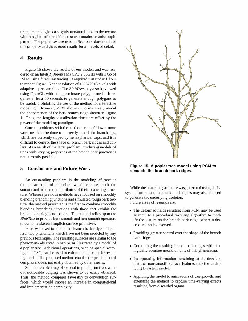
Figure 15 shows the results of our model, and was ren-dered on an Intel(R) Xeon(TM) CPU 2.66GHz with 1 Gb ofRAM using direct ray tracing. It required just under 1 hourto render Figure 15 at a resolution of 1536x2048 pixels withadaptive super-sampling. The BlobTree may also be viewedusing OpenGL with an approximate polygon mesh. It re-quires at least 60 seconds to generate enough polygons tobe useful, prohibiting the use of the method for interactivemodeling. However, PCM allows us to intuitively modelthe phenomenon of the bark branch ridge shown in Figure1. Thus, the lengthy visualization times are offset by thepower of the modeling paradigm.
Current problems with the method are as follows: morework needs to be done to correctly model the branch tips,which are currently tipped by hemispherical caps, and it isdifficult to control the shape of branch bark ridges and col-lars. As a result of the latter problem, producing models oftrees with varying properties at the branch bark junction isnot currently possible.
5 Conclusions and Future Work
An outstanding problem in the modeling of trees isthe construction of a surface which captures both thesmooth and non-smooth attributes of their branching struc-ture. Whereas previous methods have focused on smoothlyblending branching junctions and simulated rough bark tex-ture, the method presented is the first to combine smoothlyblending branching junctions with those that exhibit thebranch bark ridge and collars. The method relies upon theBlobTree to provide both smooth and non-smooth operatorsto combine skeletal implicit surface primitives.
PCM was used to model the branch bark ridge and col-lars, two phenomena which have not been modeled by anyprevious technique. The resulting surfaces are similar to thephenomena observed in nature, as illustrated by a model ofa poplar tree. Additional operations, such as spacial warp-ing and CSG, can be used to enhance realism in the result-ing model. The proposed method enables the production ofcomplex models not easily obtained by other means.
Summation blending of skeletal implicit primitives with-out noticeable bulging was shown to be easily obtained.Thus, the method compares favorably to convolution sur-faces, which would impose an increase in computationaland implementation complexity.
Figure 15. A poplar tree model using PCM tosimulate the branch bark ridges.
While the branching structure was generated using the L-system formalism, interactive techniques may also be usedto generate the underlying skeleton.
Future areas of research are:
• The deformed fields resulting from PCM may be usedas input to a procedural texturing algorithm to mod-ify the texture on the branch bark ridge, where a dis-colouration is observed.
• Providing greater control over the shape of the branchbark ridges.
• Correlating the resulting branch bark ridges with bio-logically accurate measurements of this phenomena.
• Incorporating information pertaining to the develop-ment of non-smooth surface features into the under-lying L-system model.
• Applying the model to animations of tree growth, andextending the method to capture time-varying effectsresulting from discarded organs.

6 Acknowledgments
We would like to thank the many students who have con-tributed toward implicit modeling research at the Univer-sity of Calgary. In particular, we thank Dr. Prusinkiewicz,whose tree modeling inspired this work, and for providingthe photograph of an arbutus tree, shown in Figure 2. Thiswork is partially sponsored by the Natural Sciences and En-gineering Research Council.
References
[1] V. Adzhiev, R. Cartwright, E. Fausett, A. Ossipov, A. Pasko,and V. Savchenko. HyperFun project: a framework for col-laborative multidimensional F-rep modeling. In Proceedingsof Implicit Surfaces ’99, pages 59–69, Sept. 1999.
[2] M. Aitken and M. Preston. Foliage generation and animationfor “The Lord of the Rings: The Two Towers”. SIGGRAPH2003 DVD-ROM, ACM SIGGRAPH, New York, 2003.
[3] E. Akleman, J. Chenb, and V. Srinivasan. A minimal andcomplete set of operators for the development of robust man-ifold mesh modelers. Graphical Models, 65(5):286–304,Sep 2003.
[4] A. H. Barr. Gloabl and Local Deformations of Solid Prim-itives. In Proceedings of SIGGRAPH 84, volume 18 ofComputer Graphics Proceedings, Annual Conference Se-ries, pages 21–30, 1984.
[5] J. Bloomenthal. Modeling the Mighty Maple. In Proceed-ings of SIGGRAPH 1985, volume 19, pages 305–311. ACM,Jul 1985.
[6] J. Bloomenthal. Skeletal Design of Natural Forms. Ph.D.dissertation, University of Calgary, 1995.
[7] J. Bloomenthal, editor. Introduction to Implicit Surfaces.Morgan Kaufmann, ISBN 1-55860-233-X, 1997.
[8] J. Bloomenthal and K. Shoemake. Convolution surfaces.In Proceedings of SIGGRAPH 1991, pages 251–256. ACM,1991.
[9] M.-P. Cani. Layered models with implicit surfaces.In Graphics Interface (GI’98) Proceedings, Vancouver,Canada, Jun 1998. Invited paper, published under the nameMarie-Paule Cani-Gascuel.
[10] P. de Reffye, C. Edelin, J. Francon, M. Jaeger, and C. Puech.Plant models faithful to botanical structure and develop-ment. In Proceedings of SIGGRAPH 1988, pages 151–158.ACM, 1988.
[11] M. Desbrun and M.-P. Cani-Gascuel. Active implicit surfacefor animation. Graphics Interface ’98, pages 143–150, June1998. ISBN 0-9695338-6-1.
[12] D. Frijters and A. Lindenmayer. A model for the growthand flowering of Aster novae-angliae on the basis of table(1,0)L-systems. In G. Rozenberg and A. Salomaa, editors,L-systems, Lecture Notes in Computer Science 15, pages 24–52. Springer-Verlag, Berlin, 1974.
[13] M.-P. Gascuel. An Implicit Formulation for Precise Con-tact Modeling Between Flexible Solids. Computer Graphics(Proc. SIGGRAPH 93), pages 313–320, August 1993.
[14] A. Guy and B. Wyvill. Controlled Blending For ImplicitSurfaces. In Implicit Surfaces ’95, Apr. 1995.
[15] J. C. Hart and B. Baker. Implicit modeling of tree surfaces.In Proceedings of Implicit Surfaces ’96, pages 143–152, Oct1996.
[16] M. Holton. Strands, gravity, and botanical tree imagery.Computer Graphics Forum, 13(1):57–67, 1994.
[17] H. Honda. Description of the form of trees by the parametersof the tree-like body: Effects of the branching angle and thebranch length on the shape of the tree-like body. Journal ofTheoretical Biology, 31:331–338, 1971.
[18] X. Jin, C.-L. Tai, J. Feng, and Q. Peng. Convolution sur-faces for line skeletons with polynomial weight distribu-tions. Journal of Graphics Tools, 6(3):17–28, 2001.
[19] X. Liang and B. Wyvill. Hierarchical implicit surface refine-ment. Proc. Computer Graphics International, Hong Kong,pages 291–298, 2001.
[20] A. Lindenmayer. Mathematical models for cellular interac-tion in development, Parts I and II. Journal of TheoreticalBiology, 18:280–315, 1968.
[21] B. Lintermann and O. Deussen. Interactive modelingof plants. IEEE Computer Graphics and Applications,19(1):56–65, 1999.
[22] K. Maritaud. Rendu realiste d’arbres vus de pres en imagesde synthese. PhD thesis, University de Limoges, France,December 2003.
[23] P. E. Oppenheimer. Real time design and animation of frac-tal plants and trees. In Proceedings of SIGGRAPH 1986,volume 20, pages 55–64, Aug 1986.
[24] A. Pasko, V. Adzhiev, A. Sourin, and V. Savchenko. Func-tion representation in geometric modeling: concepts, imple-mentation and applications. The Visual Computer, 2(8):429–446, 1995.
[25] G. Pasko, A. Pasko, M. Ikeda, and T. Kunnii. BoundedBlending Operations. In Proceedings of the InternationalConference on Shape Modeling and Applications (SMI2002), pages 95–103. IEEE Computer Society, May 2002.
[26] P. Prusinkiewicz, M. Hammel, J. Hanan, and R. Mech.Handbook of Formal Languages, chapter Visual models ofplant development. Springer–Verlag, Berlin, 1996.
[27] P. Prusinkiewicz and A. Lindenmayer. The AlgorithmicBeauty of Plants. Springer-Verlag, New York, 1990.
[28] A. Shigo. Tree Autopsy . Tree Care Industry, 7(6), Jun 1996.[29] Tigges. M. and Wyvill, B. Texture Mapping the BlobTree.
Implicit Surfaces, 3, Jun 1998.[30] R. F. Tobler, S. Maierhofer, and A. Wilkie. Mesh-Based
Parametrized L-Systems And Generalized Subdivision forGenerating Complex Geometry. International Journal ofShape Modeling, 8(2):173–191, Dec 2002.
[31] B. Wyvill, E. Galin, and A. Guy. Extending The CSGTree. Warping, Blending and Boolean Operations in an Im-plicit Surface Modeling System. Computer Graphics Forum,18(2):149–158, Jun 1999.