BLM National Training Center HYDRAULIC DESIGN PART 2.
14
B L M N a t i o n a l T r a i n i n g C e n t e r HYDRAULIC DESIGN PART 2
-
Upload
myles-allison -
Category
Documents
-
view
217 -
download
0
Transcript of BLM National Training Center HYDRAULIC DESIGN PART 2.
BLMN
atio
nal Tra
inin
g C
ente
rHYDRAULIC DESIGN PART 2
BLMN
atio
nal Tra
inin
g C
ente
r
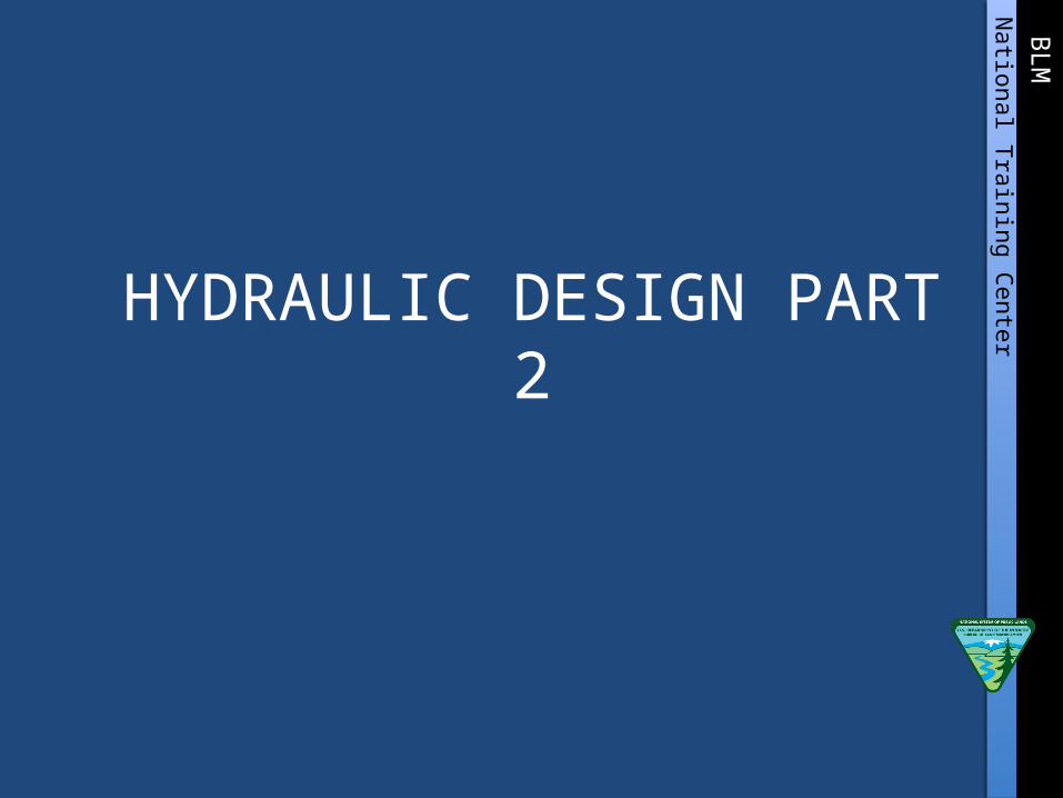
EXAMPLE 2, PUMPED AUTOMATIC PRESSURE PIPELINE DESIGN
Given: Flow rate from pump to station 120+00 is 8 gpm Existing well will produce 15 gpm; at 8 gpm well will drawdown to elevation
150 ft. Pipeline requirement will be 8 gpm. Clearance head (CH) for pipeline is 23.1 ft. Delivery pressure at all tanks shall be 20 psi. Cut-in, cut-out pressure range is 30 psi.

BLMN
atio
nal Tra
inin
g C
ente
r
BLMN
atio
nal Tra
inin
g C
ente
r

BLMN
atio
nal Tra
inin
g C
ente
r
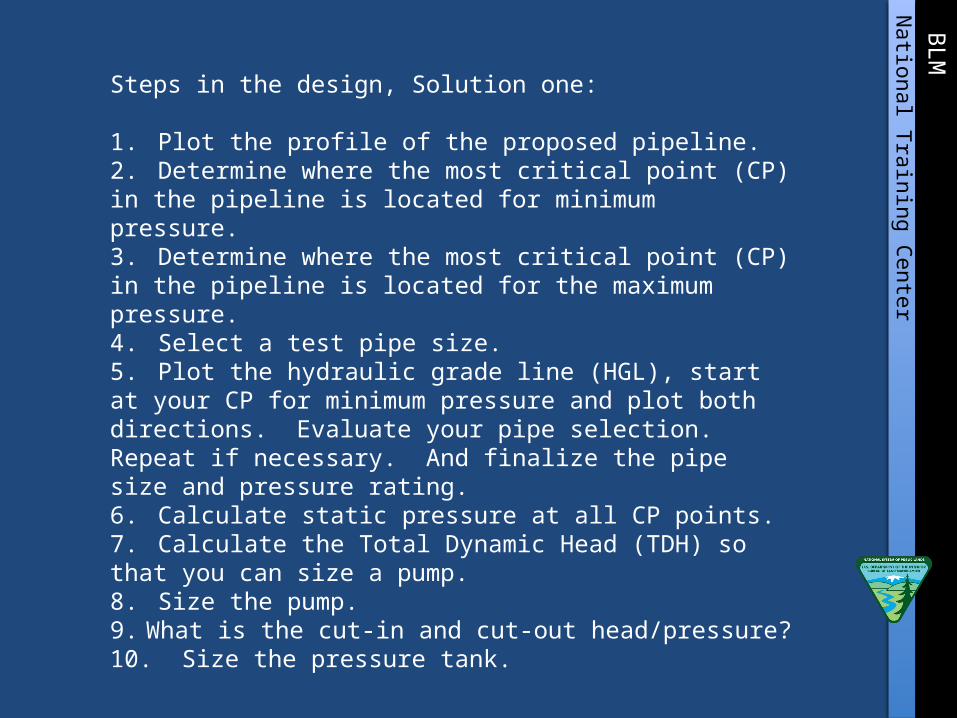
Steps in the design, Solution one:
1. Plot the profile of the proposed pipeline.2. Determine where the most critical point (CP) in the pipeline is located for minimum pressure.3. Determine where the most critical point (CP) in the pipeline is located for the maximum pressure.4. Select a test pipe size.5. Plot the hydraulic grade line (HGL), start at your CP for minimum pressure and plot both directions. Evaluate your pipe selection. Repeat if necessary. And finalize the pipe size and pressure rating.6. Calculate static pressure at all CP points.7. Calculate the Total Dynamic Head (TDH) so that you can size a pump.8. Size the pump.9. What is the cut-in and cut-out head/pressure?10. Size the pressure tank.

BLMN
atio
nal Tra
inin
g C
ente
r

BLMN
atio
nal Tra
inin
g C
ente
r
BLMN
atio
nal Tra
inin
g C
ente
r
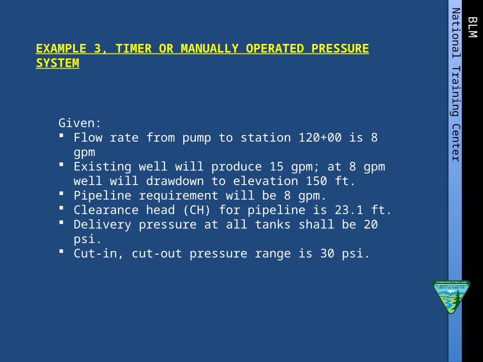
EXAMPLE 3, TIMER OR MANUALLY OPERATED PRESSURE SYSTEM
Given: Flow rate from pump to station 120+00 is 8 gpm Existing well will produce 15 gpm; at 8 gpm well will drawdown to
elevation 150 ft. Pipeline requirement will be 8 gpm. Clearance head (CH) for pipeline is 23.1 ft. Delivery pressure at all tanks shall be 20 psi. Cut-in, cut-out pressure range is 30 psi.

BLMN
atio
nal Tra
inin
g C
ente
r
BLMN
atio
nal Tra
inin
g C
ente
r
BLMN
atio
nal Tra
inin
g C
ente
r
Steps in the design, Solution one:
1. Plot the profile of the proposed pipeline.2. Determine where the most critical point (CP) in the pipeline is located for minimum pressure.3. Determine where the most critical point (CP) in the pipeline is located for the maximum pressure.4. Select a test pipe size.5. Plot the hydraulic grade line (HGL), start at your CP for minimum pressure and plot both directions. Evaluate your pipe selection. Repeat if necessary. And finalize the pipe size and pressure rating.6. Calculate static pressure at all CP points.7. Calculate the Total Dynamic Head (TDH) so that you can size a pump.8. Size the pump.9. What is the cut-in and cut-out head/pressure?10. Size the pressure tank.
BLMN
atio
nal Tra
inin
g C
ente
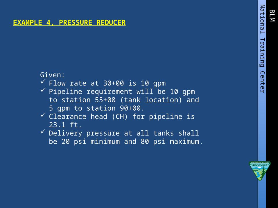
rEXAMPLE 4, PRESSURE REDUCER
Given: Flow rate at 30+00 is 10 gpm Pipeline requirement will be 10 gpm to station 55+00
(tank location) and 5 gpm to station 90+00. Clearance head (CH) for pipeline is 23.1 ft. Delivery pressure at all tanks shall be 20 psi minimum
and 80 psi maximum.
BLMN
atio
nal Tra
inin
g C
ente
r
Steps in the design, Solution one:
1. Plot the profile of the proposed pipeline.2. Determine where the most critical point (CP) in the pipeline is located for minimum pressure.3. Determine where the most critical point (CP) in the pipeline is located for the maximum pressure.4. Select a test pipe size.5. Plot the hydraulic grade line (HGL), start at your CP for minimum pressure and plot both directions. Evaluate your pipe selection. Repeat if necessary.6. Calculate static pressure at all CP points.

BLMN
atio
nal Tra
inin
g C
ente
r