BLITZRCWORKS V-22 OSPREY - Banana Hobby
16
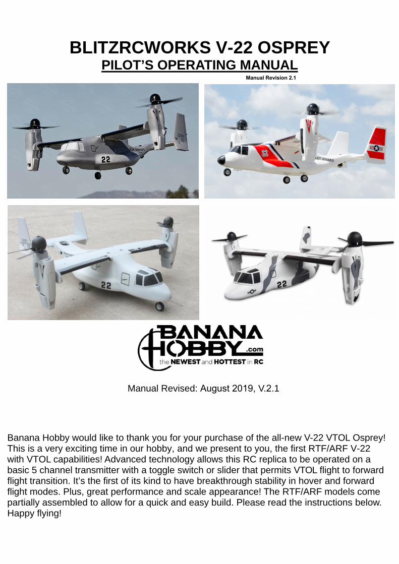
1 BLITZRCWORKS V-22 OSPREY PILOT’S OPERATING MANUAL Manual Revised: August 2019, V.2.1 Banana Hobby would like to thank you for your purchase of the all-new V-22 VTOL Osprey! This is a very exciting time in our hobby, and we present to you, the first RTF/ARF V-22 with VTOL capabilities! Advanced technology allows this RC replica to be operated on a basic 5 channel transmitter with a toggle switch or slider that permits VTOL flight to forward flight transition. It’s the first of its kind to have breakthrough stability in hover and forward flight modes. Plus, great performance and scale appearance! The RTF/ARF models come partially assembled to allow for a quick and easy build. Please read the instructions below. Happy flying! Manual Revision 2.1
Transcript of BLITZRCWORKS V-22 OSPREY - Banana Hobby
1
BLITZRCWORKS V-22 OSPREY PILOT’S OPERATING MANUAL
Manual Revised: August 2019, V.2.1
Banana Hobby would like to thank you for your purchase of the all-new V-22 VTOL Osprey! This is a very exciting time in our hobby, and we present to you, the first RTF/ARF V-22 with VTOL capabilities! Advanced technology allows this RC replica to be operated on a basic 5 channel transmitter with a toggle switch or slider that permits VTOL flight to forward flight transition. It’s the first of its kind to have breakthrough stability in hover and forward flight modes. Plus, great performance and scale appearance! The RTF/ARF models come partially assembled to allow for a quick and easy build. Please read the instructions below. Happy flying!
Manual Revision 2.1
2
Table of Contents Safety Notices ................................................................................................................................................................... 1
Model Specifications ........................................................................................................................................................ 2
Package Contents ............................................................................................................................................................. 2
Assembly and Pre-Flight Check ........................................................................................................................................ 2
Function Check ................................................................................................................................................................. 6
Center of Gravity Check ................................................................................................................................................... 9
Flight ............................................................................................................................................................................... 10
Maintenance ................................................................................................................................................................... 11
Spare Parts List ............................................................................................................................................................... 12
1: Safety Notices This product is not a toy. Improper operation may cause bodily injury or property damage. It is highly suggested for beginners new to this hobby to seek help from an experienced RC pilot.
1.1 Please follow all lithium-polymer battery safety procedures and warnings. If you are new to using Li-Po batteries, be sure to research their specific handling. Do not puncture the battery. Do not store the battery fully charged as it will lose its capacity overtime and discharge. Do not overcharge or over discharge the battery. Keep the battery away from flammable materials. Do not charge the lithium polymer battery unattended. Monitoring the Li-Po charge and checking the charge process is highly suggested. Remember, Lithium Polymer batteries should not get warm during the charging process. If the battery becomes warm or hot during charging, please disconnect the battery from the charger immediately. Consult with the dealer for more information if needed.
1.2 To avoid injury and damage, do not operate this model in a crowded space, in the presence of high voltage cables, and keep away from buildings. Be sure to follow local, state-wide or country-wide rules and regulations.
This model and its electronic components are not suitable for flying in rainy or windy weather. Avoid flying when wind speed reaches 6 MPH or higher.
1.3 To avoid damage or bodily harm, the propeller must be undamaged and fastened. Do not attempt to repair broken propellers.
1.4 Make sure to use fully charged or brand new AA batteries in the transmitter/remote control to prevent signal loss. If you are using your own transmitter system, please be sure to fully charge your transmitter if applicable.
1.5 To begin operation, the transmitter must be turned on first with the throttle stick set to its lowest possible position. Next, the V-22 MUST BE on a flat surface. Plug in the battery to the V-22 and allow at least 5 seconds for the Flight Control Board unit to initialize before picking up the V-22 and taking flight. After flight, always turn off the model first by unplugging the battery before turning off the transmitter.
1.6 Never operate this model within the proximity of an airport without prior permission or you will be fined, and potentially arrested for safety violations. U.S. RC pilots, more details here: https://www.faa.gov/uas/getting_started/fly_for_fun/
1

3
2: Model Specifications (ARF)
• Wingspan: 700mm (Without Motor Nacelles)• Length: 848mm• Weight: 1150g (Without Battery)• Motor: (2) 3510 brushless motors, (1) 2520 brushless motor (EDF)• Battery: 4S 2200MAH - 2800MAH (Flight time 3-7 minutes, varies on battery/flying
style)• ESC: (2) 30A Brushless ESC (1) 20A Brushless ESC• Servo: (3) 9g Standard and (2) 17g Metal Gear ServosFeatures:
With our advanced VTOL technology, this model is capable of switching between hovering/landing like a helicopter (VTOL) to flying like a standard fixed wing airplane. Some of its capabilities include flying like a helicopter/multirotor to flying like an airplane. It’s capable of maneuvers such as rolls, loops, and other aerobatic stunts, but exercise extreme caution.
3: Package Contents
3.1 Airframe (Fuselage, Main Wing, Horizontal and Vertical Stabilizers) 3.2 Propeller Assembly (Left and Right Blade Sets and Spinner Sets) 3.3 Landing Gear Set 3.4 Manual Booklet 3.5 4S 2200mAh Lithium-Polymer Battery (RTF ONLY) 3.6 Balance Charger (RTF ONLY) 3.7 Transmitter and Receiver (RTF ONLY) 3.8 M3 Hex Wrench
4: Assembly and Pre-Flight Check This model arrives partially assembled. The fuselage has been mostly assembled and tested at the factory, but additional assembly is required for the tail section.
4.1 You will require glue such as foam-safe epoxy to attach the vertical and horizontal stabilizers to the fuselage. Epoxy or CA glue(Foam-safe) is suggested. Make sure to center the two vertical stabilizers parallel to the centerline of the fuselage, as shown on the images below. Always test fit the vertical stabilizers and horizontal stabilizer to insure proper fitment before applying adhesive. Remove any paint on the surface where glue will be applied for a stronger adhesion. TIP: You can use packing tape, clear scotch tape to remove the paint from areas where glue will be applied. Simply press the tape on the areas and peel the tape off. Most time the paint will peel away with the tape.
2
4
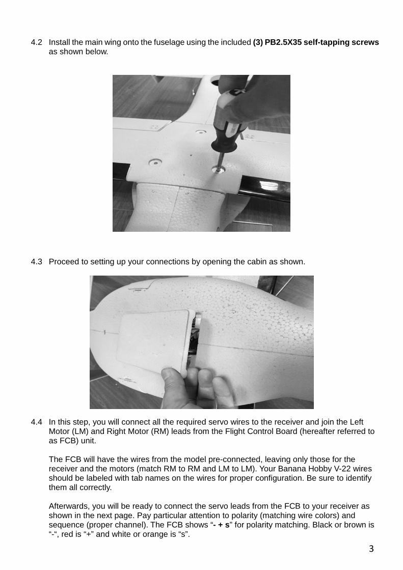
4.2 Install the main wing onto the fuselage using the included (3) PB2.5X35 self-tapping screws as shown below.
4.3 Proceed to setting up your connections by opening the cabin as shown.
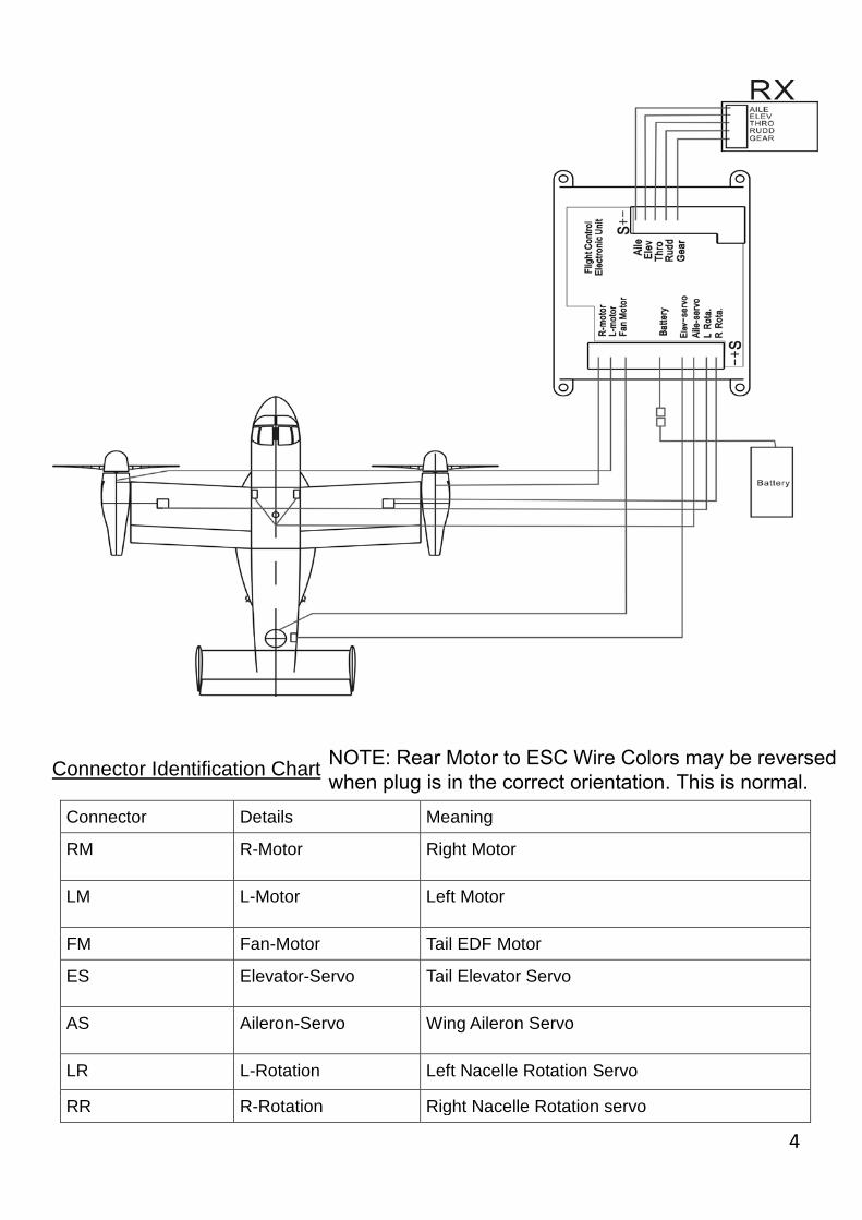
4.4 In this step, you will connect all the required servo wires to the receiver and join the Left Motor (LM) and Right Motor (RM) leads from the Flight Control Board (hereafter referred to as FCB) unit.
The FCB will have the wires from the model pre-connected, leaving only those for the receiver and the motors (match RM to RM and LM to LM). Your Banana Hobby V-22 wires should be labeled with tab names on the wires for proper configuration. Be sure to identify them all correctly.
Afterwards, you will be ready to connect the servo leads from the FCB to your receiver as shown in the next page. Pay particular attention to polarity (matching wire colors) and sequence (proper channel). The FCB shows “- + s” for polarity matching. Black or brown is “-“, red is “+” and white or orange is “s”.
3
5
Connector Identification Chart
Connector Details Meaning
RM R-Motor Right Motor
LM L-Motor Left Motor
FM Fan-Motor Tail EDF Motor
ES Elevator-Servo Tail Elevator Servo
AS Aileron-Servo Wing Aileron Servo
LR L-Rotation Left Nacelle Rotation Servo
RR R-Rotation Right Nacelle Rotation servo
4
NOTE: Rear Motor to ESC Wire Colors may be reversed when plug is in the correct orientation. This is normal.
6
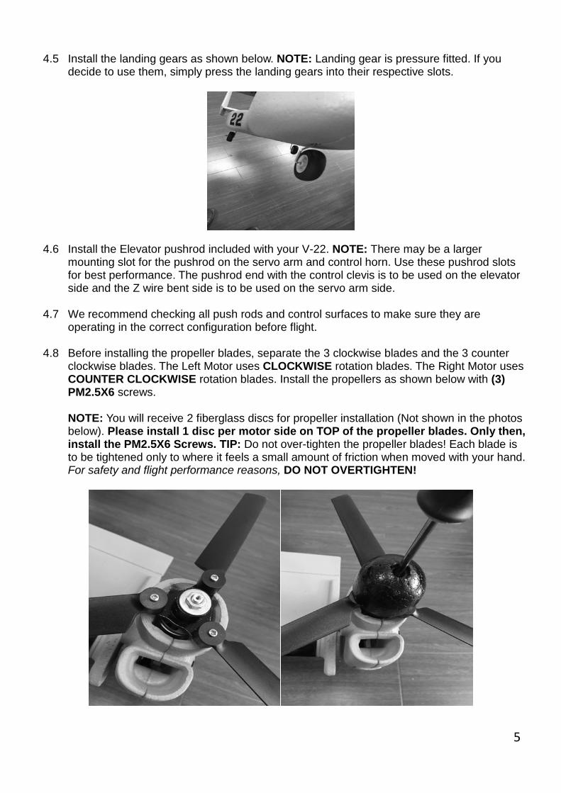
4.5 Install the landing gears as shown below. NOTE: Landing gear is pressure fitted. If you decide to use them, simply press the landing gears into their respective slots.
4.6 Install the Elevator pushrod included with your V-22. NOTE: There may be a larger mounting slot for the pushrod on the servo arm and control horn. Use these pushrod slots for best performance. The pushrod end with the control clevis is to be used on the elevator side and the Z wire bent side is to be used on the servo arm side.
4.7 We recommend checking all push rods and control surfaces to make sure they are operating in the correct configuration before flight.
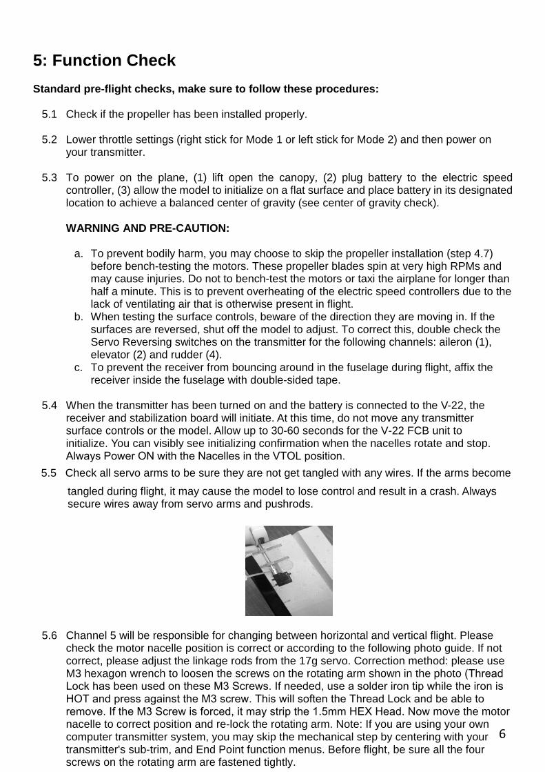
4.8 Before installing the propeller blades, separate the 3 clockwise blades and the 3 counter clockwise blades. The Left Motor uses CLOCKWISE rotation blades. The Right Motor uses COUNTER CLOCKWISE rotation blades. Install the propellers as shown below with (3) PM2.5X6 screws.
NOTE: You will receive 2 fiberglass discs for propeller installation (Not shown in the photos below). Please install 1 disc per motor side on TOP of the propeller blades. Only then, install the PM2.5X6 Screws. TIP: Do not over-tighten the propeller blades! Each blade is to be tightened only to where it feels a small amount of friction when moved with your hand. For safety and flight performance reasons, DO NOT OVERTIGHTEN!
5
7
5: Function Check Standard pre-flight checks, make sure to follow these procedures:
5.1 Check if the propeller has been installed properly.
5.2 Lower throttle settings (right stick for Mode 1 or left stick for Mode 2) and then power on your transmitter.
5.3 To power on the plane, (1) lift open the canopy, (2) plug battery to the electric speed controller, (3) allow the model to initialize on a flat surface and place battery in its designated location to achieve a balanced center of gravity (see center of gravity check).
WARNING AND PRE-CAUTION:
a. To prevent bodily harm, you may choose to skip the propeller installation (step 4.7)before bench-testing the motors. These propeller blades spin at very high RPMs andmay cause injuries. Do not to bench-test the motors or taxi the airplane for longer thanhalf a minute. This is to prevent overheating of the electric speed controllers due to thelack of ventilating air that is otherwise present in flight.
b. When testing the surface controls, beware of the direction they are moving in. If thesurfaces are reversed, shut off the model to adjust. To correct this, double check theServo Reversing switches on the transmitter for the following channels: aileron (1),elevator (2) and rudder (4).
c. To prevent the receiver from bouncing around in the fuselage during flight, affix thereceiver inside the fuselage with double-sided tape.
5.4 When the transmitter has been turned on and the battery is connected to the V-22, the receiver and stabilization board will initiate. At this time, do not move any transmitter surface controls or the model. Allow up to 30-60 seconds for the V-22 FCB unit to initialize. You can visibly see initializing confirmation when the nacelles rotate and stop. Always Power ON with the Nacelles in the VTOL position.
5.5 Check all servo arms to be sure they are not get tangled with any wires. If the arms become tangled during flight, it may cause the model to lose control and result in a crash. Always secure wires away from servo arms and pushrods.
5.6 Channel 5 will be responsible for changing between horizontal and vertical flight. Please check the motor nacelle position is correct or according to the following photo guide. If not correct, please adjust the linkage rods from the 17g servo. Correction method: please use M3 hexagon wrench to loosen the screws on the rotating arm shown in the photo (Thread Lock has been used on these M3 Screws. If needed, use a solder iron tip while the iron is HOT and press against the M3 screw. This will soften the Thread Lock and be able to remove. If the M3 Screw is forced, it may strip the 1.5mm HEX Head. Now move the motor nacelle to correct position and re-lock the rotating arm. Note: If you are using your own computer transmitter system, you may skip the mechanical step by centering with your transmitter's sub-trim, and End Point function menus. Before flight, be sure all the four screws on the rotating arm are fastened tightly.
6
8
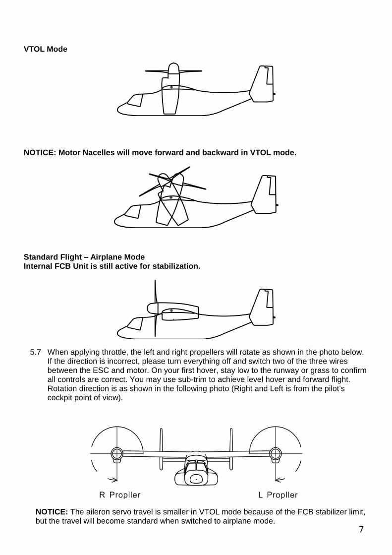
VTOL Mode
NOTICE: Motor Nacelles will move forward and backward in VTOL mode.
Standard Flight – Airplane Mode Internal FCB Unit is still active for stabilization.
5.7 When applying throttle, the left and right propellers will rotate as shown in the photo below. If the direction is incorrect, please turn everything off and switch two of the three wires between the ESC and motor. On your first hover, stay low to the runway or grass to confirm all controls are correct. You may use sub-trim to achieve level hover and forward flight. Rotation direction is as shown in the following photo (Right and Left is from the pilot’s cockpit point of view).
NOTICE: The aileron servo travel is smaller in VTOL mode because of the FCB stabilizer limit, but the travel will become standard when switched to airplane mode.
7

9
5.8 Double check the nacelle rotation by using the CH. 5 function. Be sure the Nacelle's achieve proper rotation levels.
5.9 Check channels 1, 2 and 4 for proper response. Be sure the control surfaces are neutral when not in use. Remember, make sure the surfaces are not reversed!
5.10 Double check the entire fuselage assembly as well as the tail section prior to flight.
NOTICE: Trim Setup: When hovering in VTOL flight, the model can be adjusted by using the trim tabs. This can be used when there is forward/backward or side by side drifting.
NOTICE: Winds can affect stability when in VTOL mode because of the model’s characteristics. If to be flown in LIGHT wind conditions, stability increases when the nose is against the wind or flying forward. Please consider do not allow the model have a severe tail wind or to fly backwards in a quick manner. This may result in stability/vibrating issues and lead to a loss of altitude. Flying at altitudes near the ground can also be dangerous since it does not allow much time to recover.
NOTICE: Remember to initialize the model on flat or hard level surfaces. A solid or hard floor is suggested. Soft level surfaces such as grass could cause issues due to a slight unevenness. Uneven surfaces such as a car hood top is not advised. For best results, have the model placed on a flat surface before plugging in the battery. This will allow it enough time to initialize correctly.
8
***IMPORTANT CALIBRATION NOTICE!
Before each flight always power on your V-22 on a flat surface and allow up to 30 seconds for the FC Controller to initialize. Do not move the V-22 during this initializing process. Once the V-22 has initialized, PLEASE rotate the nacelles using the transition switch to full forward flightmode and back to VTOL mode at least 3 times. If in the event you see the ailerons and thenacelles deflect violently in opposing directions, DO NOT FLY. Follow the steps below tocalibrate the FC board for flight:
*Flight Control Board Calibration/Throttle Calibration*:
When you have powered on your transmitter and plugged in the V-22 flight battery, flip your Nacelle transition switch from VTOL to Forward Flight QUICKLY up to 10 to 12 times. Do not wait for the Nacelles to reach full down or full up. This is for calibration only. Flip in a quick Up, Down, Up, Down, Up, Down about 10 times and then stop and wait. You should see the V-22 Ailerons deflect one direction and back to neutral. Possibly the Nacelles may perform the same as well as the motors may initialize quickly. This will indicate FC Calibration successful. If you do not see the motions stated above, perform the Nacelle switch flips again until you see the results. This is a crucial step to insure your V-22 will transition smoothly! Be sure to transition from VTOL to Forward flight towards a head wind if applicable and with plenty of altitude! For more information, please watch Pete's V-22 Calibration and Flight video at the YouTube link below:
https://www.youtube.com/watch?v=BPY_VfW3wegor
https://www.youtube.com/user/bananahobby
10
6: Center of Gravity Check
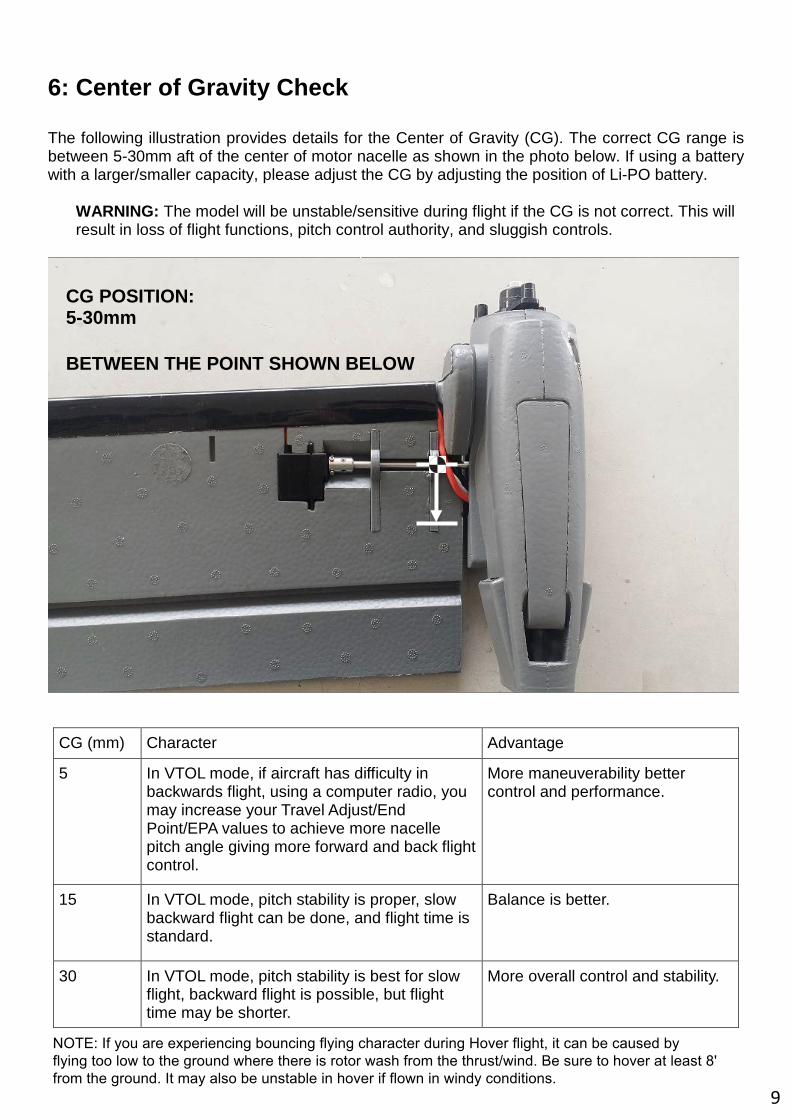
The following illustration provides details for the Center of Gravity (CG). The correct CG range is between 5-30mm aft of the center of motor nacelle as shown in the photo below. If using a battery with a larger/smaller capacity, please adjust the CG by adjusting the position of Li-PO battery.
WARNING: The model will be unstable/sensitive during flight if the CG is not correct. This will result in loss of flight functions, pitch control authority, and sluggish controls.
CG (mm) Character Advantage
5 In VTOL mode, if aircraft has difficulty in backwards flight, using a computer radio, you may increase your Travel Adjust/End Point/EPA values to achieve more nacelle pitch angle giving more forward and back flight control.
More maneuverability better control and performance.
15 In VTOL mode, pitch stability is proper, slow backward flight can be done, and flight time is standard.
Balance is better.
30 In VTOL mode, pitch stability is best for slow flight, backward flight is possible, but flight time may be shorter.
More overall control and stability.
CG POSITION: 5-30mm
BETWEEN THE POINT SHOWN BELOW
9
NOTE: If you are experiencing bouncing flying character during Hover flight, it can be caused byflying too low to the ground where there is rotor wash from the thrust/wind. Be sure to hover at least 8' from the ground. It may also be unstable in hover if flown in windy conditions.

11
7: Flight
If you are an experienced pilot, flight can be achieved indoors or outdoors due to the V-22’s VTOL capabilities. We suggest to choose a room measured at 20ftx20ftx20ft for VTOL mode ONLY. An outdoor flying area with calm weather is best for maiden flights.
WARNING: Please organize the wires after the battery is put into the fuselage to avoid any movement issues with the motor nacelles. Please check the motor nacelle movement to make sure they work normally and double check the CG balance.
1. This model’s VTOL mode is similar to a standard quadcopter. Controlling the model mayfeel similar to a standard quadcopter.
2. As a pilot, several styles of flight are available such as taking off in VTOL mode andswitching to airplane mode during flight.
3. VTOL flight may feel more stable than standard airplane flight because of onboard flightcontroller and stabilizer.
4. When taking off in VTOL mode, it is suggested to fly the model higher than 100 ft. to makesure it is able to clear any obstacles, and to be able to safely switch between flight modeswhile keeping the throttle in position. The onboard flight controller and stabilizer will maketransition between flight modes are smooth as possible, but be sure to keep speed and liftto prevent a stall.
5. When changing back to VTOL mode, it’s advised to be at least 100 ft. high.
WARNING:
1. When changing from standard flight mode to VTOL mode, please keep throttle up anddo not input elevator, rudder or aileron because the model itself will finish the transfersmoothly. The model may lose control or crash if any additional inputs are applied on theelevator, rudder or aileron while it is in transition mode.
2. Be sure the Li-PO battery still has sufficient charge before switching to VTOL mode toland. If the battery is nearly drained before switching to VTOL mode, the model maycrash due to loss of power. Consult with the dealer for more information if needed.
3. When in VTOL mode, if pitch stability is affected by wind direction or other reasons,remain calm and apply any of the necessary control inputs to land safely.
10
12
8: Maintenance 8.1 To power down, make sure to unplug the battery first before turning off the transmitter.
Doing so will help to prevent the receiver from potentially connecting with another system. ALWAYS unplug the aircraft battery FIRST before powering down the transmitter!
8.2 Check the propellers for any damage and to be sure they are still secured.
8.3 For precautionary reasons, be sure to check the motor and ESC wires as they can come loose from flight vibrations.
8.4 Check the fit between main wings and tail section on the fuselage.
8.5 Check to make sure the landing gear is secured.
8.6 Check the main wing screws as they may come loose when many flights have been logged on the V-22.
8.7 Make sure all control pushrods and the clevises are secure. Check the clevis from flight to flight for any cracks or splits.
8.8 Check control surface horns on the ailerons and elevator to make sure the arm backing is tight.
8.9 On bright sunny days or warm days, avoid direct sunlight exposure to your V-22 to prevent damage.
8.10 Store your V-22 in a climate controlled room.
8.11 If touch-up paint is needed, any model paint or acrylic paint will work fine. Do not use any automotive paint!
11

13
9: Spare Parts List
Part Number Part Name Description Photo
15201 Fuselage Main Fuselage Body
15202 Main Wing Main Wing
15203 Tail Section Vertical Stabilizer and Horizontal Stabilizer (Part listing may vary)
15204 Left and Right Motor Nacelles
Left and Right Motor Compartments (Additional parts may vary)
15205 Propeller Spinner Set Two Propeller Spinners
12

14
15206 Canopy Painted Canopy
15207 Landing Gear Set Front and Main Gear Set
15208 Propeller Left and Right Blade Set (three pieces each side)
15209 Propeller Collet
Aluminum Propeller Collet
15210 Tail EDF Tail EDF Set
15211 Rotating Motor Axis Rotating Axis Parts
13
15
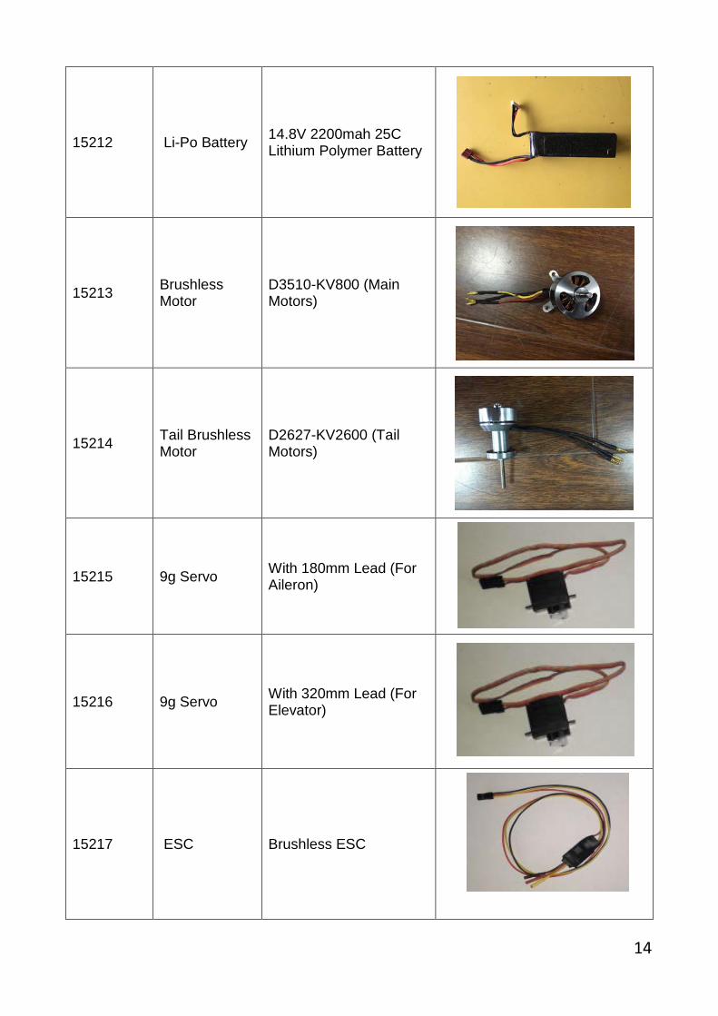
15212 Li-Po Battery 14.8V 2200mah 25C Lithium Polymer Battery
15213 Brushless Motor
D3510-KV800 (Main Motors)
15214 Tail Brushless Motor
D2627-KV2600 (Tail Motors)
15215 9g Servo With 180mm Lead (For Aileron)
15216 9g Servo With 320mm Lead (For Elevator)
15217 ESC Brushless ESC
14
16
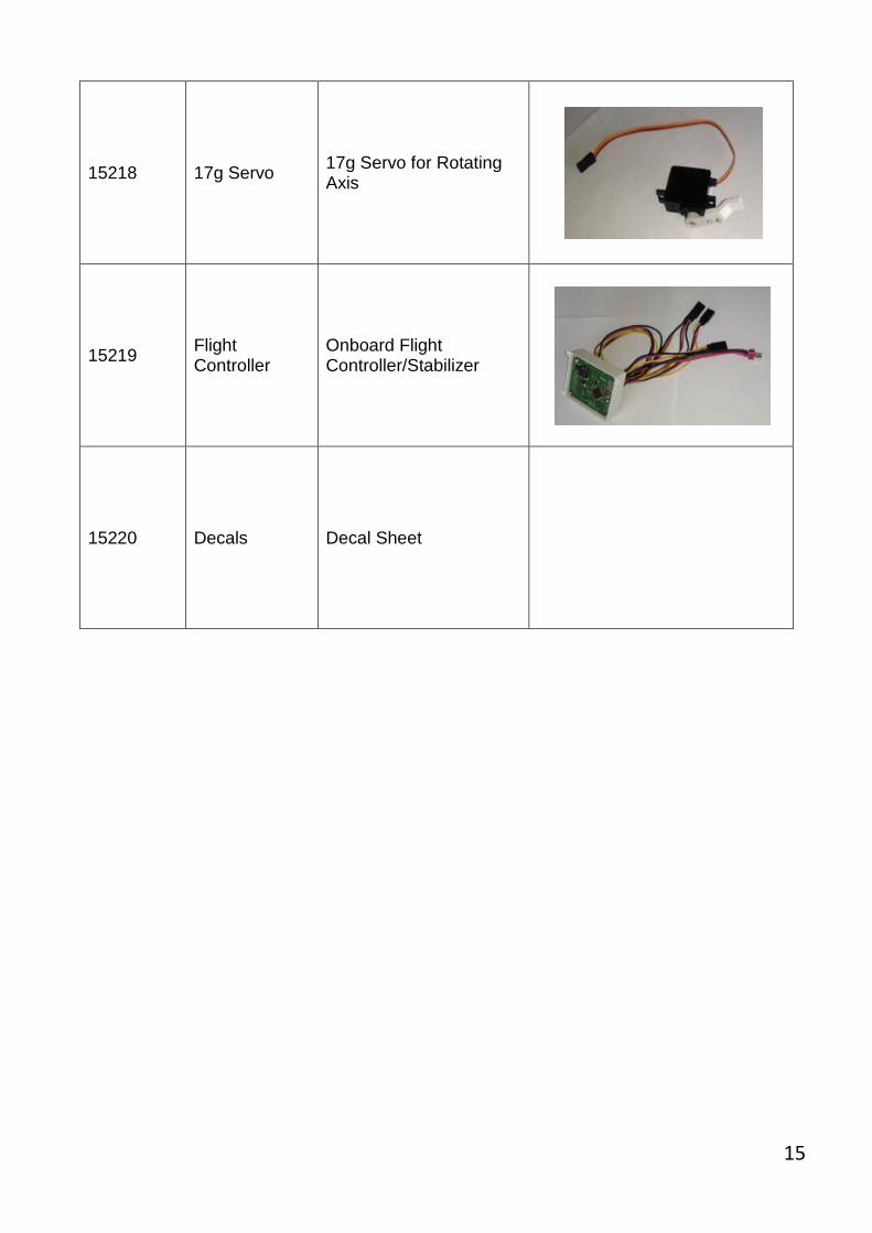
15218 17g Servo 17g Servo for Rotating Axis
15219 Flight Controller
Onboard Flight Controller/Stabilizer
15220 Decals Decal Sheet
15