
BLIND NAVIGATION SYSTEM BY USING ARDUINO WITH …eprints.utem.edu.my/16411/1/Blind Navigation System...
24
i BLIND NAVIGATION SYSTEM BY USING ARDUINO WITH 1SHEELD MASNAH GAMBILOK THIS REPORT IS SUBMITTED IN PARTIAL FULFILLMENT OF REQUIREMENTS FOR THE BACHELOR DEGREE OF ELECTRONIC ENGINEERING(INDUSTRIAL ELECTRONIC) FAKULTI KEJURUTERAAN ELEKTRONIK DAN KEJURUTERAAN KOMPUTER UNIVERSITI TEKNIKAL MALAYSIA MELAKA JUNE 2015
Transcript of BLIND NAVIGATION SYSTEM BY USING ARDUINO WITH …eprints.utem.edu.my/16411/1/Blind Navigation System...

i
BLIND NAVIGATION SYSTEM BY USING ARDUINO WITH 1SHEELD
MASNAH GAMBILOK
THIS REPORT IS SUBMITTED IN PARTIAL FULFILLMENT OF REQUIREMENTS FOR THE BACHELOR DEGREE OF ELECTRONIC
ENGINEERING(INDUSTRIAL ELECTRONIC)
FAKULTI KEJURUTERAAN ELEKTRONIK DAN KEJURUTERAAN KOMPUTER UNIVERSITI TEKNIKAL MALAYSIA MELAKA
JUNE 2015

ii
“Saya akui laporan ini adalah hasil kerja saya sendiri kecuali ringkasan dan petikan yang tiaptiap
satunya telah saya jelaskan sumbernya.”
Tandatangan : ………………………………………
Nama Penulis : MASNAH GAMBILOK
Tarikh : 8 JUN 2015

iii
“Saya/kami akui bahawa saya telah membaca karya ini pada pandangan saya/kami karya ini
adalah memadai dari skop dan kualiti untuk tujuan penganugerahan Ijazah Sarjana Muda
Kejuruteraan Elektronik (Elektronik Industri).”
Tandatangan : ……………………………………………….
Nama Penyelia : PUAN KHAIRUN NISA BINTI KHAMIL
Tarikh : 8 JUN 2015

iv
For My Beloved Family And Friends

v
ACKNOWLEDGEMENT
I would like to express my highest gratitude to God and to both of my
parents, as because of them I manage to be where I am now. This project
development would be hard if i don’t have them as a biggest comforter and supporter
in my life. My big appreciation also goes to my supervisor, Madam Khairun nisa Bt
Khamil, for she is the sources of some of the idea, concept and materials. As for our,
panel, Mr Vigneswara Rao A/L Ganapathy (Co – supervisor) and Dr Wira Hidayat,
thank for their comments and suggestions, I had able to see and discover the
drawback of some part in this project and think of ways to improve my design and
scope. It is undeniable that all the lecturers in Universiti Teknikal Malaysia Melaka
that had pour their knowledge in many circumstances for students including me, are
deserve to be given the biggest applause as they were not only teaching by book but
also fully by heart. For my friends in 4BENE and all the senior that always give their
hand to share knowledges, I sincerely will not forget it.

vi
ABSTRACT
Blind Navigation by using Arduino and 1sheeld is about project that helps
blind community in the whole world to get a better access to the environment. The
project provides alert system through vibration and speech system by using cane,
1Sheeld, Arduino Programming , ultrasonic sensor and vibration motor. Nowadays,
when it comes to travelling alone, blind people always prepared all his/her guider,
whether the cane,the surrounding noise, a guide dog, an assistive technology, or a
relative. This project is an assistive technology which consist of four ultrasonic
sensor( above waistline, left, right and front detector) mounted on the cane gripper
and two mini Grove vibration motor embedded on the gripper. The system also
provides alternative ways everytime an obstacles is detected.
ABSTRAK
Projek Alat Pembantu Orang Buta Dengan Menggunakan Arduino Dan
1Sheeld adalah projek yang dicipta khas untuk meberikan informasi yang lebih
banyak kepada orang buta tentang keadaan sekeliling mereka. Projek ini
menyediakan sistem pemberitahuan atau amaran melalui getaran dan bunyi, dan
komponen yang terlibat ialah tongkat, 1Sheeld, Pengprograman Arduino, sensor
ultrasonik, dan motor getaran. Pada masa kini, orang buta sentiasa ditemani tongkat,
bunyi sekeliling,anjing penunjuk arah, teknologi atau keluarga. Projek ini terdiri
daripada empat sensor ultrasonik (pengesan halangan atas paras pinggang, kiri,
kanan dan depan), dipasang pada bahagian atas pemegang dan dua motor getaran di
bahagian dalam pemegang. Sistem ini juga memberikan arah alternatif setiap kali
objek dikesan.

vii
CONTENT
CHAPTER ABOUT PAGE
PROJECT TITLE I
DECLARATION II
DEDICATION III
ACKNOWLEDGEMENT V
ABSTRACT VI
ABSTRAK VI
CONTENT VII
LIST OF TABLE X
LIST OF FIGURE XI
I INTRODUCTION 1
1.1 PROJECT SUMMARY 1
1.2 INTRODUCTION 2
1.3 PROBLEM STATEMENT 3
1.4 OBJECTIVES 4
1.5 IMPORTANCE OF PROJECT 5
1.6 SCOPE 5
1.7 ORGANIZATION OF THESIS 5
II LITERATURE REVIEW 7
2.1 INTRODUCTION 7
2.2 MY 2ND EYE 8

viii
2.3 GPS BASED VIRTUAL EYEFOR BLIND PEOPLE 9
2.4 SMART CANE : ASSISTIVE CANE FOR VISUALLY 10
IMPAIRED PEOPLE
2.5 EVALUATION OF ELECTRONIC HAPTIC 11
DEVICE FOR BLIND PEOPLE
(ELECTRONIC LONG CANE): A CASE STUDY.
2.6 NAVEYE 12
2.7 MASTER RESEARCH TABLE 14
2.8 REVIEW ON COMPONENTS 18
2.8.1 Ultrasonic Sensor 18
2.8.1.1 Distance Measurement 20
For Obstacle Avoidance
2.8.2 Vibration Motor 21
2.8.3 1sheeld 23
2.8.4 Arduino Uno 26
2.8.5 Power Supply 27
III METHODOLOGY 29
3.1 INTRODUCTION 29
3.2 DEVELOPMENT PHASE 30
3.3 SYSTEM DESIGN 31
IV RESULT AND DISCUSSION 36
4.1 INTRODUCTION 36
4.2 SIMULATION RESULT 37
4.2.1 Ultrasonic Sensor 37
4.2.2 Simulation With Vibration Motor 38

ix
4.2.3 Two Vibration Motors And 39
Four Ultrasonic Sensors
4.3 PROTOTYPE INSTALLATION 44
4.4 DISCUSSION 48
V CONCLUSION AND SUGGESTION 49
5.1 CONCLUSION 49
5.2 SUGGESTIONS FOR FUTURE WORK 50
APPENDIX A 51
APPENDIX B 57
REFERENCES 59- 60

x
LIST OF TABLES
NO TITLE PAGE
2.7.1 MASTER RESEARCH TABLE 17
3.1.2 GANTT CHART 30
3.3.1 SENSOR POSITION WITH 32
CORRESPONDING SETPOINT
3.3.2 VIBRATION ALERT POSITION 33
3.3.3 AUDIO OUTPUT FOR EACH SENSOR 34

xi
LIST OF FIGURES
NO TITLE PAGE
1.2.1 BLIND PEOPLE STATISTIC GLOBALLY 2
2.2.1 MY 2ND EYE BLOCK DIAGRAM 8
2.2.2 MY 2ND EYE PROTOTYPE 8
2.2.3 LOCATION OF VIBRATION MOTORS 8
2.3.1 BLOCK DIAGRAM FOR GPS VIRTUAL EYE 9
2.4.1 SMART CANE 10
2.5.1 COMPONENTS INSIDE GRIPPER 11
2.5.2 ORDINARY CANE LIMITATION 11
2.5.3 ELECTRONIC LONG CANE IMPROVE SPATIAL 11
PERCEPTION
2.6.1 NAVEYE FUNCTIONAL OPERATION 12
2.6.2 CANE IMPLEMENTATION 13
2.8.1.1 TIMING DIAGRAM OF SOUND SIGNAL 20
2.8.1.2 EXAMPLE OF ULTRASONIC SCHEMATIC 20
WITH ARDUINO BOARD
2.8.2.1 CYLINDER TYPE VIBRATION MOTOR 21

xii
2.8.2.2 COIN TYPE VIBRATION MOTOR 21
2.8.3.1 1SHEELD HARDWARE PART 25
2.8.3.2 1SHEELD SOFTWARE PART 25
2.8.4.1 ARDUINO UNO BOARD 26
3.2.1 PROJECT PLANNING FLOWCHART 31
3.3.1 HOW CANE DESIGN WORKS 31
3.3.2 CANE WORKING PRINCIPLE 34
3.3.3 CLOSE LOOP DIAGRAM OF SYSTEM’S OPERATION 35
4.2.1.1 WIRING FOR 1 ULTRASONIC SENSOR 37
4.2.1.2 CODE FOR 1 ULTRASONIC SENSOR 37
4.2.1.3 OUTPUT READING OF SENSOR IN FORM 38
OF DISTANCE WITH SPEECH OUTPUT
4.2.2.1 VIBRATION MOTOR CONNECTION TO GROVE 38
BASE SHIELD BOARD
4.2.2.2 WIRING FOR 1 SENSOR AND 1 VIBRATION MOTOR 38
4.2.2.3 OUTPUT CODE FOR MOTOR AND SENSOR 39
4.2.2.4 OUTPUT FROM SERIAL MONITOR 39
4.2.3.1 CONNECTION FOR TWO VIBRATION MOTORS 40
4.2.3.2 WIRING FOR FOUR SENSORS AND FOUR MOTORS 40
4.2.3.3 RIGHT AND LEFT SENSORS OPERATION 41
4.2.3.4 FRONT AND UPWARD SENSORS OPERATION 41
4.2.3.5 CODE FOR CONDITION WHEN ALL SENSORS IN 41
HIGH AND ALL IN LOW CONDITION

xiii
4.2.3.6 RIGHT SENSOR’S OUTPUT 42
4.2.3.7 LEFT’S SENSOR’S OUTPUT 42
4.2.3.8 FRONT SENSOR’S OUTPUT 42
4.2.3.9 UPWARD SENSOR’S OUTPUT 43
4.2.3.10 OUTPUT WHEN ALL DISTANCE ARE 43
LESS THAN SETPOINT
4.2.3.11 OUTPUT WHEN ALL DISTANCE ARE 43
MORE THAN SETPOINT
4.3.1 ULTRASONIC SENSORS CASING DIMENSION 44
4.3.2 ULTRASONIC SENSORS POSITIONS AND 44
DIRECTIONS
4.3.3 BOX DIMENSION OF CONTROLLER WITH 45
1SHEELD AND BASE SHIELD BOARD
4.3.4 ULTRASONIC SENSOR OF CANE 46
4.3.5 CONTROLLER BOX OF CANE 46
4.3.6 ULTRASONIC SENSORS WITH CONTROLLER
BOX
4.3.7 GRIPPER OF CANE 47
4.3.8 FULL CANE PROTOTYPE 47
4.3.9 CANE IN FOLDED CONDITION 47

1
CHAPTER I
INTRODUCTION
1.1 Project Summary
This project is about a blind navigation system that sends information
wirelessly from Arduino’s shield to a smartphone, in order to alert the user about the
distance of obstacles through speech warning and vibration. Alternative ways also
notified each time an obstacle is detected. Four ultrasonic sensors are mounted on
cane to detect objects from all four directions, front, left, right and over waistline
space. The ultrasonic sensor is chosen because it performs distance calculation which
is not affected by ambient light with better detection range compared to the infrared
sensor. Speech to alert the user will be written in arduino coding as a distance
notification.
2
1.2 Introduction
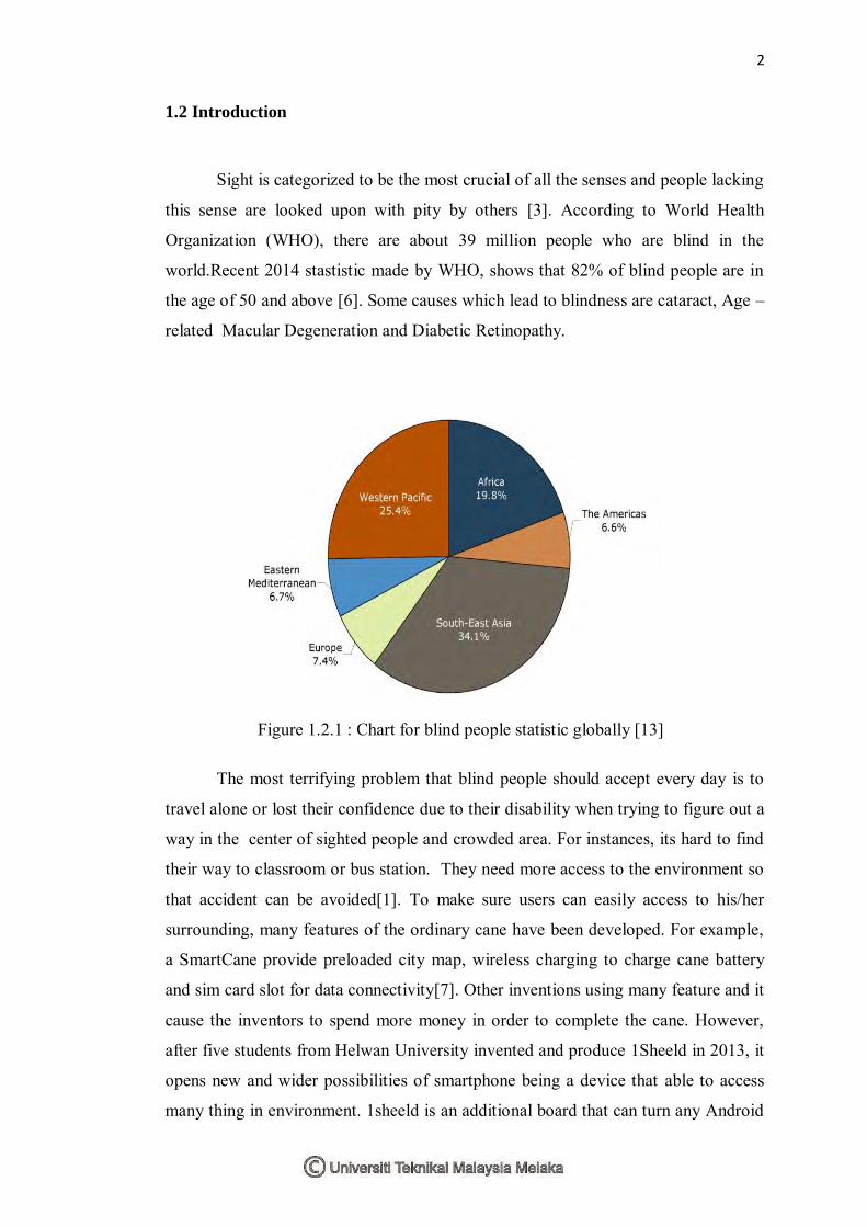
Sight is categorized to be the most crucial of all the senses and people lacking
this sense are looked upon with pity by others [3]. According to World Health
Organization (WHO), there are about 39 million people who are blind in the
world.Recent 2014 stastistic made by WHO, shows that 82% of blind people are in
the age of 50 and above [6]. Some causes which lead to blindness are cataract, Age –
related Macular Degeneration and Diabetic Retinopathy.
The most terrifying problem that blind people should accept every day is to
travel alone or lost their confidence due to their disability when trying to figure out a
way in the center of sighted people and crowded area. For instances, its hard to find
their way to classroom or bus station. They need more access to the environment so
that accident can be avoided[1]. To make sure users can easily access to his/her
surrounding, many features of the ordinary cane have been developed. For example,
a SmartCane provide preloaded city map, wireless charging to charge cane battery
and sim card slot for data connectivity[7]. Other inventions using many feature and it
cause the inventors to spend more money in order to complete the cane. However,
after five students from Helwan University invented and produce 1Sheeld in 2013, it
opens new and wider possibilities of smartphone being a device that able to access
many thing in environment. 1sheeld is an additional board that can turn any Android
Figure 1.2.1 : Chart for blind people statistic globally [13]

3
smartphone into actuator or sensors in the real world[8]. In blind aids prespective,
some feature of 1sheeld can be applied, such as text to speech to alert the user about
obstacles.By using 1Sheeld, cost is reduced by reducing the item list to create this
project, as there is no need to purchase additional hardware feature such as speech
Integrated Circuit to fulfil or provide many functionality of the cane. In addition, in
this 21st century, smartphone already become a neccescity and most people using this
can download 1sheeld application easily to transform their smartphone into a
sopishticated sensors.
1.3 Problem Statement
In growing technologies, many types of wearable computers and assistive
technology were created for visually impaired people with varying amounts of
cost.However, Until today, traditional white cane is still the number one choice
among blind people, due to its low cost, as low as RM15 in Malaysia. Some
inventions have drastically changed their lifestyle, such as electronic canes like Ultra
cane (Sound Foresight Technology LTD) and Bat K sonar (Bay Advanced
Technologies Ltd) [1]. The ultra cane provide protection on the user by using 2
ultrasound sensor attached in front, foward the chest and head of the user [3].
However, ultra-cane is expensive (estimated at RM 2957.04 and RM 2299.92) and it
detects excessive vibration with heavy pedestrian flow even though it can sense
signal over the waist line level [1]. Some invention also needs a separate power
supply or navigator which is requiring the user to bring it in a bag every time they
travel outdoor [2]. These bulky designs will tire out the user, especially in a long way
travelling. Other than that, those novel invention such as smart belt and other cane
features require necessary skills and training phase of the user [3].

4
1.4 Objective
This project will fulfil the following objectives;
1. To design an assistive technology for visually impaired people in which can
detect obstacles and provides alternative ways.
2. To alarm the user through speech (earphone/headphone) and vibration to
determine the obstacles direction sources.
3. To build low cost blind navigation using Arduino with 1sheeld to connect to
smartphone.

5
1.5 Importance of project
1. To enhance the mobility of blind people.
2. protecting blind people from possible hazard
3. less costly product will be affordable for many people.
1.6 Scope
Speech alert delivered to smartphone using 1sheeld text-to-speech feature.
Vibration alert triggered in 2 mini vibration motor.
4 ultrasonic sensor are set up on the cane gripper to detect obstacle from four
directions( up, front ,left ,right)
Controller used is the Arduino Uno.
1.7 Organization Of Thesis
Each chapter’s goal is described and arranged as below;
CHAPTER 1
Introduction, objective, scope and project summary are written to gives better
understanding on where this project direction, and generally explain the
significance of this project. This chapter also try to discover the problem or
deficiency that has emerged in previous inventions.
CHAPTER 2
All data collection such as theories and possible solutions are written in this
chapter. This chapter is neccesary to enable or verify that this invention is
achieveable, based on many method from vary sources of reference. In other
words, chapter two is more on comparisons of researches, fundamental
working principles of component involved and formulas.
6
CHAPTER 3
This chapter is considered as one of the most crucial part and all the
statement has to be written thoughtfully. Chapter three is about the way of
managing this project and provides first step on much clearer view on how
the theories and researches can be adapted in this project to solve the
problem in chapter 1. It is consist of a Gantt chart, flowchart and the system
design.
CHAPTER 4
The circuit and arduino program are analysed, simulated and explained in this
chapter. It involves the program for grove mini vibration motor and ultrasonic
sensor. The prototype body was decided after all the functionality met the
objectives requirement.
CHAPTER 5
Chapter 5 conclude all the significant achievement of this project and consists
of some suggestion for future work to improvises its feature.

7
CHAPTER II
LITERATURE REVIEW
2.1 Introduction
In this chapter, all the sources from journals, books and websites that related
to this project is clarified. This chapter covering five different types of
research about cane invention that had been produced in several years before
and also elaborate about some background of component specification which
are expected to be implemented in this project.
8
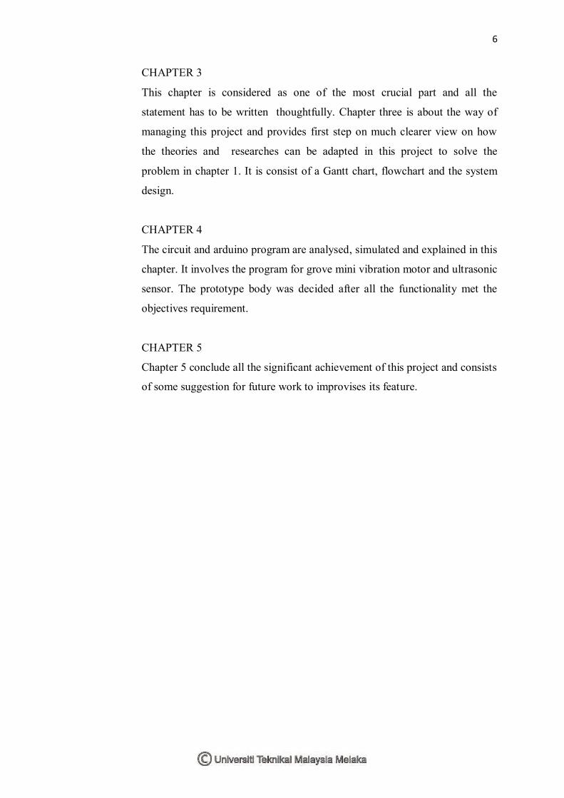
2.2 My 2nd
Eye
My 2nd Eye use solar panel to charge the battery. The power produced will be
used by the motor driver, 4 vibration motor, PIC microcontroller and 4 infrared
sensors. When obstacle detected by infrared sensor, signal will be sended to
controller and controller will deliver signal about the obstacle direction source and
distance in the glove’s vibration motor. The vibration concept is same with a phone
vibration. This type of warning system is a good choice as it use human sense of
touch and therefore, the fastest way to alert them[4]. However, this invention does
not provides alternative ways for the user.
Figure 2.2.1: My 2nd Eye Block diagram[4] Figure 2.2.2: My 2nd Eye Prototype [4]
Figure 2.2.3: Location of vibration motors [4]
9
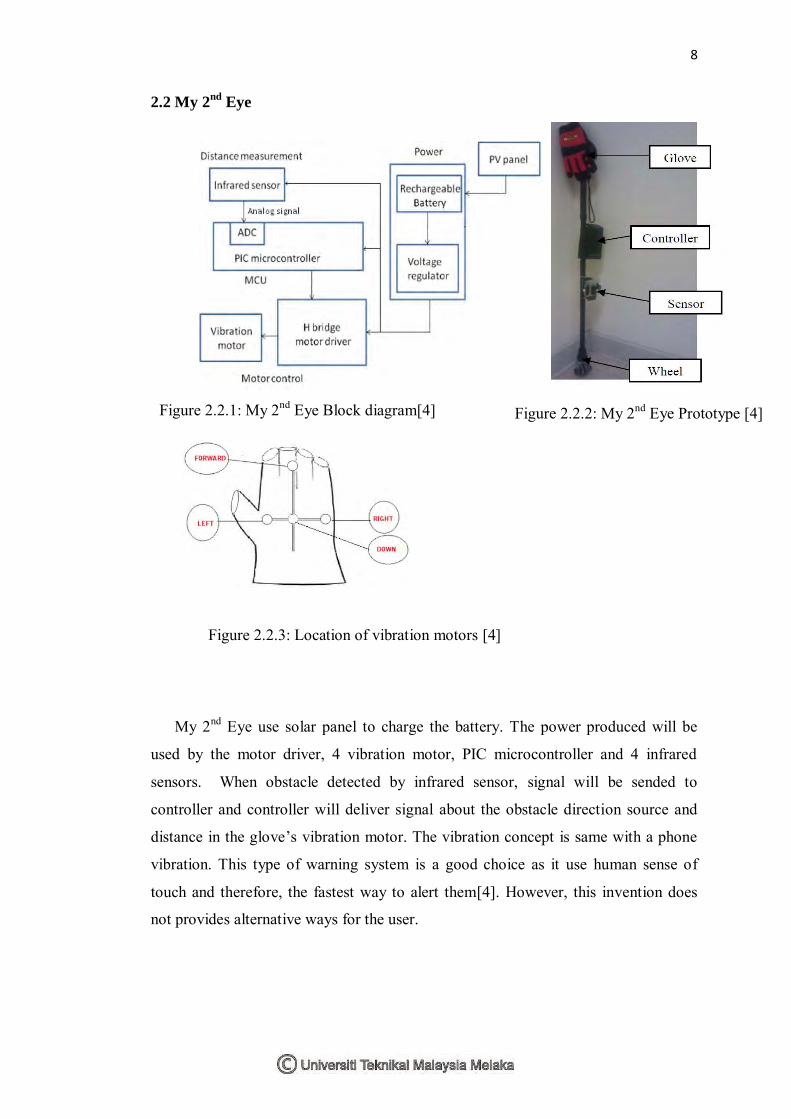
2.3 GPS based Virtual Eye for the Blind People
Global Positioning System (GPS) and Global System for Mobile
communications (GSM) are interfaced to the microcontroller to detect the blind
person location [3]. Microcontroller get the location from the GPS modem and
transmit the location to the GSM modem which will send a SMS messages to the all
saved numbers[3].Which is means, if the blind person is missing, his/her relative can
identify the person coordinate location as tha GPS will send the information
continuously to the controller. The coordintae location can be received immediately
as the relative send one message such as ‘TRACK’ to the blind person. The
controller used for this system is the ARM7 based ATMEGA 328 microcontroller.
For its obstacle avoidance, GPS based Virtual Eye use 1 ultrasonic sensor with
distance ranging from 2cm-400cm non-contact measurement function. Obstacle
notification also provided by speech ic (APR33A3). APR33A3 is integrated circuit
that can record and play audio in 11 Minutes . The controller will send signal about
the obstacle to the speech ic and it will inform the user that obstacle has been
detected. To obtain better speech alert, headphone is applied as well, directly from
the speech ic. Power supply used consist of battery, rectifier, filter and regulation[3].
Advantages of this system are, it is applicable inside and outside of house
and also in known and unknown evironment such as airport, hospital and market.
However, even though it is a dynamic system, the item list is too many and this
subsequently increase the cost of product. For example, item such as GSM module,
GPS module and speech ic(APR33A3) need to be purchased. This system does not
Figure 2.3.1: Block diagram for GPS based Virtual Eye [3]
10
use vibration as in MY 2nd EYE and it can detect obstacle in one direction only as
there is only one ultarsonic sensor which is mounted to the cane.
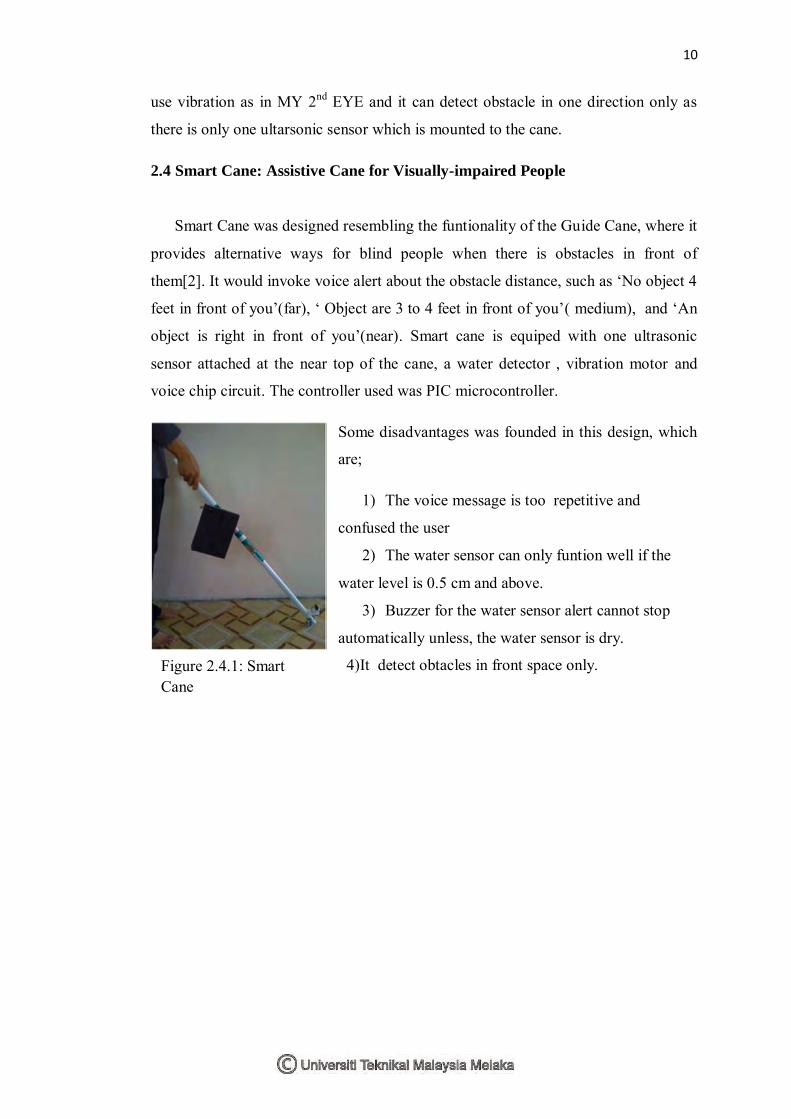
2.4 Smart Cane: Assistive Cane for Visually-impaired People
Smart Cane was designed resembling the funtionality of the Guide Cane, where it
provides alternative ways for blind people when there is obstacles in front of
them[2]. It would invoke voice alert about the obstacle distance, such as ‘No object 4
feet in front of you’(far), ‘ Object are 3 to 4 feet in front of you’( medium), and ‘An
object is right in front of you’(near). Smart cane is equiped with one ultrasonic
sensor attached at the near top of the cane, a water detector , vibration motor and
voice chip circuit. The controller used was PIC microcontroller.
Some disadvantages was founded in this design, which
are;
1) The voice message is too repetitive and
confused the user
2) The water sensor can only funtion well if the
water level is 0.5 cm and above.
3) Buzzer for the water sensor alert cannot stop
automatically unless, the water sensor is dry.
4)It detect obtacles in front space only.
Figure 2.4.1: Smart Cane
prototype[2]
11
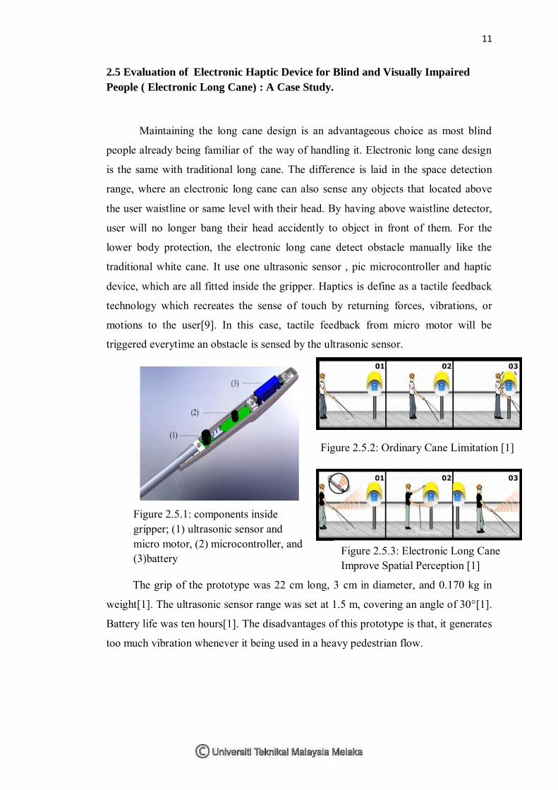
2.5 Evaluation of Electronic Haptic Device for Blind and Visually Impaired
People ( Electronic Long Cane) : A Case Study.
Maintaining the long cane design is an advantageous choice as most blind
people already being familiar of the way of handling it. Electronic long cane design
is the same with traditional long cane. The difference is laid in the space detection
range, where an electronic long cane can also sense any objects that located above
the user waistline or same level with their head. By having above waistline detector,
user will no longer bang their head accidently to object in front of them. For the
lower body protection, the electronic long cane detect obstacle manually like the
traditional white cane. It use one ultrasonic sensor , pic microcontroller and haptic
device, which are all fitted inside the gripper. Haptics is define as a tactile feedback
technology which recreates the sense of touch by returning forces, vibrations, or
motions to the user[9]. In this case, tactile feedback from micro motor will be
triggered everytime an obstacle is sensed by the ultrasonic sensor.
The grip of the prototype was 22 cm long, 3 cm in diameter, and 0.170 kg in
weight[1]. The ultrasonic sensor range was set at 1.5 m, covering an angle of 30°[1].
Battery life was ten hours[1]. The disadvantages of this prototype is that, it generates
too much vibration whenever it being used in a heavy pedestrian flow.
Figure 2.5.1: components inside gripper; (1) ultrasonic sensor and micro motor, (2) microcontroller, and (3)battery
Figure 2.5.2: Ordinary Cane Limitation [1]
Figure 2.5.3: Electronic Long Cane Improve Spatial Perception [1]


