BLE Series - Oriental Motor U.S.A. … · 2018-05-15 · BLE Series For detailed ... assignment,...
40
D-42 D-42 ORIENTAL MOTOR GENERAL CATALOG 2015/2016 Page Features D-42 / System Configuration D-45 / Product Line D-46 / Specifications D-51 / Characteristics D-54 Dimensions D-59 / Connection and Operation D-70 / Motor and Driver Combinations D-79 Standard Type RS-485 Communication Type Brushless Motor and Driver Package BLE Series ●For detailed information about regulations and standards, please see the Oriental Motor website. Standard Type RS-485 Communication Type View Expanded Product Information, Specifications, CAD, Accessories & more online. Visit www.orientalmotor.com/catalog or use the QR code and select "BLE Series". • A brushless motor and driver package designed with all the necessary functions for effective speed control. • Speed Control Range: 100∼4000 r/min (speed ratio 40:1) • By using the control module (sold separately), additional performance and functions are possible. • An RS-485 communications type is also available for easy connection to a wide variety of industrial networks and host systems. About FLEX ➜ Page F-4 <Additional Information> •Technical reference ➜ Page H-1 •Regulations & Standards ➜ Page I-2 ■Features Speed Control Range of 100∼4000 r/min (Speed ratio 40:1) Compared with conventional products, the speed control range is greatly expanded. Use in high-speed applications even at a maximum speed of 4000 r/min is possible. Speed control range BLE Series: 100∼4000 r/min (speed ratio 40:1) Conventional Product: 300∼3000 r/min (speed ratio 10:1) 0 3000 1000 300 100 4000 2000 Speed [r/min] BLE Series [120 W (1/6 HP)] Conventional Product [120 W (1/6 HP)] Speed Control Range 100∼4000 r/min [Comparison Using 120 W (1/6 HP) Output Model] Maximum Speed 4000 r/min The starting torque is twice the rated torque. [N·m] 0.6 0.4 0.2 0.8 0 20 40 60 80 100 [oz-in] Torque Excellent Speed Stability The speed regulation (load) is ±0.5%. For this reason, this mechanism ensures that the motor drives at a stable speed over its entire speed range from low to high, even when the load condition fluctuates. [Conventional Product] [BLE Series ✽ ] Load −1% Voltage ±1% Temperature ±1% Load ±0.5% Voltage ±0.5% Temperature ±0.5% ✽During Analog Setting Compact yet Powerful High power is achieved with a slim body, efficient gearhead and a compact design allowing for additional space savings. 105 mm (4.13 in.) □90 mm (□3.54 in.) [BLE Series 120 W (1/6 HP)] Mass: 3.0 kg (6.6 lb.) Energy Savings Brushless motors use permanent magnets in the rotor. In comparison with inverter-controlled motors, they are high-efficiency with little loss, which means that energy savings is possible. Speed Control during Vertical Operation is Possible The electromagnetic brake type motor enables stable speed control even during vertical operation (gravitational operation). The electromagnetic brake is automatically controlled via the driver in accordance with the operation command signal. When the power is turned OFF, such as during a blackout, the motor stops instantaneously to hold the load in place. Note ●Since regenerated energy is produced during vertical operation, a regeneration unit, sold separately, is required. Regeneration units ➜ Page D-188 Additional Performance and Function Functionality and performance can be improved by using in combination with the control module OPX-2A or the data setting software MEXE02. ●Control Module OPX-2A (Sold separately) ●Data Setting Software MEXE02 The software can be downloaded from the Oriental Motor website. Various Settings Speed, torque limit, acceleration time, deceleration time, I/O assignment, gear ratio, speed increasing ratio, conveyor gear ratio, conveyor speed increasing ratio, speed attainment range, overload warning level, overload warning function (enable/disable), JOG (test) run speed, JOG (test) run torque, digital/analog input signal selection ●Up to 16 points of operating data (speed, torque limit, acceleration time, and deceleration time) can be set ✽1 Monitoring Function (OPX-2A) Speed, conveyor transportation speed, load factor, operating data No., alarm/ warning (code indication), alarm/warning log (code indication), I/O monitor Monitoring Function (MEXE02) Status monitor: Speed, gear shaft speed, conveyor speed, load factor, operating selection number, alarm/warning, alarm/warning log I/O monitor: I/O signals, current internal/external potentiometer setting Waveform monitor: Setting speed, detected speed, I/O signals Test Function I/O test, JOG (test) operation Data Copy Download, upload, query ✽2 , reset ✽1 Specifications for the RS-485 communication type. Specifications of the standard type are up to 8 points. ✽2 This function is only for the control module (OPX-2A). W Load or
Transcript of BLE Series - Oriental Motor U.S.A. … · 2018-05-15 · BLE Series For detailed ... assignment,...

D-42
D-42
ORIENTAL MOTOR GENERAL CATALOG 2015/2016
Page Features D-42 / System Configuration D-45 / Product Line D-46 / Specifications D-51 / Characteristics D-54
Dimensions D-59 / Connection and Operation D-70 / Motor and Driver Combinations D-79
Standard Type
RS-485
Communication
Type
Brushless Motor and Driver Package
BLE Series
●For detailed information about regulations and standards, please see the Oriental Motor website.
Standard Type RS-485 Communication Type
View Expanded Product Information, Specifications, CAD, Accessories & more online.Visit www.orientalmotor.com/catalog or use the QR code and select "BLE Series".
• A brushless motor and driver package designed with all the necessary functions for effective speed control.
• Speed Control Range: 100∼4000 r/min (speed ratio 40:1)
• By using the control module (sold separately), additional performance and functions are possible.
• An RS-485 communications type is also available for easy connection to a wide variety of industrial networks and host systems.
About FLEX ➜ Page F-4
<Additional Information>•Technical reference ➜ Page H-1•Regulations & Standards ➜ Page I-2
■Features
Speed Control Range of 100∼4000 r/min (Speed ratio 40:1)Compared with conventional products, the speed control range is greatly expanded. Use in high-speed applications even at a maximum speed of 4000 r/min is possible.
Speed control range BLE Series: 100∼4000 r/min (speed ratio 40:1) Conventional Product: 300∼3000 r/min (speed ratio 10:1)
0 30001000300100 40002000Speed [r/min]
BLE Series
[120 W (1/6 HP)]
Conventional Product
[120 W (1/6 HP)]
Speed Control Range 100∼4000 r/min
[Comparison Using 120 W (1/6 HP) Output Model]
Maximum Speed
4000 r/min
The starting torque is twice the rated torque.[N·m
]
0.6
0.4
0.2
0.8
0
20
40
60
80
100
[oz-
in]
Torq
ue
Excellent Speed StabilityThe speed regulation (load) is ±0.5%.For this reason, this mechanism ensures that the motor drives at a stable speed over its entire speed range from low to high, even when the load condition fluctuates.
[Conventional Product] [BLE Series✽]Load −1%
Voltage ±1%Temperature ±1%
Load ±0.5%Voltage ±0.5%
Temperature ±0.5% ✽During Analog Setting
Compact yet PowerfulHigh power is achieved with a slim body, efficient gearhead and a compact design allowing for additional space savings.
105 mm(4.13 in.)
□90
mm
(□3.
54 in
.)
[BLE Series 120 W (1/6 HP)]
Mass: 3.0 kg (6.6 lb.)
Energy SavingsBrushless motors use permanent magnets in the rotor. In comparison with inverter-controlled motors, they are high-efficiency with little loss, which means that energy savings is possible.
Speed Control during Vertical Operation is PossibleThe electromagnetic brake type motor enables stable speed control even during vertical operation (gravitational operation).The electromagnetic brake is automatically controlled via the driver in accordance with the operation command signal. When the power is turned OFF, such as during a blackout, the motor stops instantaneously to hold the load in place.Note
●Since regenerated energy is produced during vertical operation, a regeneration unit, sold separately, is required. Regeneration units ➜ Page D-188
Additional Performance and FunctionFunctionality and performance can be improved by using in combination with the control module OPX-2A or the data setting software MEXE02.
●Control Module OPX-2A (Sold separately)
●Data Setting Software MEXE02The software can be downloaded from the Oriental Motor website.
Various Settings
Speed, torque limit, acceleration time, deceleration time, I/O assignment, gear ratio, speed increasing ratio, conveyor gear ratio, conveyor speed increasing ratio, speed attainment range, overload warning level, overload warning function (enable/disable), JOG (test) run speed, JOG (test) run torque, digital/analog input signal selection● Up to 16 points of operating data (speed, torque limit, acceleration
time, and deceleration time) can be set✽1
Monitoring Function(OPX-2A)
Speed, conveyor transportation speed, load factor, operating data No., alarm/warning (code indication), alarm/warning log (code indication), I/O monitor
Monitoring Function(MEXE02)
Status monitor: Speed, gear shaft speed, conveyor speed, load factor, operating selection number, alarm/warning, alarm/warning log
I/O monitor: I/O signals, current internal/external potentiometer settingWaveform monitor: Setting speed, detected speed, I/O signals
Test Function I/O test, JOG (test) operationData Copy Download, upload, query✽2, reset
✽1 Specifications for the RS-485 communication type. Specifications of the standard type are up to 8 points.
✽2 This function is only for the control module (OPX-2A).
WLoad
or

D-43
Brushless Motors/AC Speed Control Motors D-43
Brushless
Motors
Overview,
Product
Series
AC InputBMU
AC Input BLE
AC Input BLF
AC Input BX
DC Input BLH
DSC
BHF
AC Speed
Control
Motors
Accessories
Installation
CAD DataManuals
www.orientalmotor.com Technical Support
TEL: (800) 468-3982E-mail: [email protected]
◇Speed Control Range Expanded to 80∼4000 r/minThe digital speed setting function expands the speed control range to cover 80∼4000 r/min (speed ratio 50:1).
1000
80 4000 Speed [r/min]
Torq
ue
When Using an OPX-2A
(Digital Setting)
◇Improved Speed Regulation
[BLE Series] [When using digital speed setting]Load ±0.5%
Voltage ±0.5%Temperature ±0.5%
Load ±0.2%Voltage ±0.2%
Temperature ±0.2%
◇Multistep Speed-Change Operation up to 16 Speeds is Possible✽
Multistep speed-change operation up to 16 speeds is possible using the OPX-2A or MEXE02. Speed setting in 1 r/min units as well as separate setting of the acceleration and deceleration time are possible.
No.8No.7
No.6No.5
No.4No.3
No.2No.1
Motor Operation Pattern
Spee
d[r
/min
]
Time ✽Specifications for the RS-485 Communication Type. Up to 8 types of operations are possible for the standard type.
◇Limiting the Motor Output TorqueThe motor output torque can be suppressed in accordance with the application and use condition.
Press Applications, etc.
Brake to Produce Tension
Tension
◇Various Digital Indications are Possible (Control module OPX-2A)Speed, load factor, alarm code, etc. can be displayed digitally.
●The speed can be displayed as the speed of the gearhead output shaft.
Speed (r/min) Transportation Speed (m/min)
Load Factor (%) Alarm Code
Gearhead Rated Life of 10000 Hours
The rated life of the parallel shaft gearhead and hollow shaft flat gearhead is 10000 hours. The parallel shaft gearhead has a long life that is twice as long as that of a conventional product.
●The parallel shaft gearheads for the 60 W (1/12 HP) and 120 W (1/6 HP) models have a tapped hole at the output shaft end.
Space Saving is Achieved with a Hollow Shaft Flat Gearhead
Direct connection to the drive shaft is possible without using a coupling, which will enable space saving.
Space Saving
●Refer to page D-14 for further information on the features of parallel shaft gearheads and hollow shaft flat gearheads.
Cable Length and Flexible Extension Cable Can be Selected
◇The Included Cable is 3 m (9.8 ft.)Comes with a cable that is 3 m (9.8 ft.) in length for connecting the motor to the driver.
Connection Cable (Included)
◇Cables up to 20 m (65.6 ft.) are Available (Sold separately)When the distance between the motor and the driver is 5 m (16.4 ft.) or longer, an accessory connection cable (sold separately) must be used. The distance between the motor and the driver can be extended up to 20 m (65.6 ft.).
●Connection Cables ➜ Page D-183
◇Flexible Extension Cables are Also Available (Sold separately)
Use the flexible connection cable in applications where the cable is bent and flexed.
●Flexible Connection Cables ➜ Page D-183
■Product Line
2 different types are available based on the system requirements. ●Standard Type ● RS-485 Communication Type ●Motor Types
Combination Type with Parallel Shaft GearheadStandard or with electromagnetic brake
Combination Type with Hollow Shaft Flat GearheadStandard or with electromagnetic brake
Round Shaft Type
Standard or with electromagnetic brake
Output Power 30 W (1/25 HP), 60 W (1/12 HP), 120 W (1/6 HP)

D-44
D-44 Brushless Motors/BLE Series
ORIENTAL MOTOR GENERAL CATALOG 2015/2016
Page Features D-42 / System Configuration D-45 / Product Line D-46 / Specifications D-51 / Characteristics D-54
Dimensions D-59 / Connection and Operation D-70 / Motor and Driver Combinations D-79
Standard Type
RS-485
Communication
Type
Connecting to a Wide Variety of Industrial Networks and Host Systems
In addition to the conventional I/O control, FA network control is now possible using Modbus (RTU) or network converters.
RS-485 Communication Type Standard Type
I/O Control Serial Communication Control
Control from a Computer or Touch Panel
FA Network Control
② RS-485
① I/O ② Modbus (RTU)
Network Converter
③ FA Network
CC-LinkMECHATROLINK-MECHATROLINK-
EtherCAT
Power Supply Module
CPUModule
I/OModule
Power Supply Module
CPUModule
Serial Communication
Module
Power Supply Module
CPUModule
FA Network Module
Touch Panel Touch-Screen
Panel ComputerComputeror
Serial Communication Board (RS-485)
② Modbus (RTU)
Various Settings Speed Setting
Control Module
(Sold separately)
Data Setting Software
Connection with the host system and control (configuration, operation, output signal indication) are performed via either ① I/O, ② Modbus (RTU)/RS-485, or ③ FA network.
Settings can also be performed easily using the following options.
External Speed Potentiometer
(Included)
External DC Voltage
(Not supplied) RS-485 Communication Type
0∼10 VDC
I/O Control
① I/O
Power Supply Module
CPUModule
I/OModule
Standard Type
① I/O ② Modbus (RTU)/RS-485 ③ FA NetworkConnect directly to a switch box or PLC to construct an operation system controlled via I/O communication.
RS-485 communication can be used to set operating data and parameters, as well as input operation commands.Up to 31 drivers can be connected to 1 serial communication driver. There is a function that enables multiple shafts to be started simultaneously. The Modbus (RTU) protocol is supported and can be used to connect to panel computers and PCs.
By using a network converter (sold separately), CC-link communication, MECHATROLINK communication or EtherCAT communication is possible. All of these can be used to set operating data and parameters, as well as input operation commands.
◇Advantages of the RS-485 Communication TypeThe BLE Series FLEX RS-485 Communication Type can be controlled entirely from a host system because operation, configuration, and monitoring are fed back to the host system. When controlling with a touch-screen or panel computer, load factor and other output signals can be monitored.
●The motor can be controlled directly from the host system such as a touch-screen or touch-screen PLC.
The motor outputs its operating status such as motor speed and load factor to the host system to help improve
equipment reliability.
●The motor is controlled through inputs received from a switch box, PLC, or the like.
Motor speed, alarm, and other signals are output to the master control system.
· Touchscreen · Touch-screen
· Touch-Screen PLC
PLC
Speed Indicator
Standard Type
InputOperation CommandsSpeed Selection Input
Control Module
or
Data Setting Software
Setting
OutputSpeed OutputAlarm Output
InputOperation CommandsSpeed Selection Input
SettingSpeedTorque LimitMotor Rotation DirectionAcceleration and Deceleration TimeOther Settings
Output
OutputSpeed Output
Various Settings
Output
●Standard Type ●RS-485 Communication Type
● SpeedOutputs the motor speed, gear shaft speed, etc.
● AlarmGenerated when overload, overvoltage, overcurrent,
etc. occur.
● Load FactorOutputs the torque generated by the motor as a
percentage with 100% as the rated torque.
● WarningGenerated when overload, communication error, etc.
occur.
● Torque LimitOutputs the setting value when limiting the torque.
RS-485 Communication Type
Settings, operations, and monitoring can be managed collectively by the master control system without going through PLC
Various output signals, such as load factor, can be monitored
Motor control is performed through a PLC
For settings and monitoring, a separate accessory is required

D-45
Brushless Motors/AC Speed Control Motors D-45
Brushless
Motors
Overview,
Product
Series
AC InputBMU
AC Input BLE
AC Input BLF
AC Input BX
DC Input BLH
DSC
BHF
AC Speed
Control
Motors
Accessories
Installation
CAD DataManuals
www.orientalmotor.com Technical Support
TEL: (800) 468-3982E-mail: [email protected]
Combination Type
(Motor and gearhead)
Driver✽2
Connection Cable (Included)
External Speed
Potentiometer (Included)
■ System Configuration ✽1 Not supplied
Control Module
➜ Page A-303Data Setting Software
Communication Cable
➜ Page A-303
Accessories (Sold separately)
Example of System Confi guration●
BLE Series
Combination Type with
Parallel Shaft
Sold Separately
Connection Cable
[7 m (23.0 ft.)]
DIN Rail Installation
PlatesMounting Bracket Flexible Coupling
BLE512AR5S-3 CC07BLE PADP03 SOL5M8 MCL5518F12$687.00 $127.00 $7.00 $34.00 $97.00
● The system configuration shown above is an example. Other combinations are also available.
BLE Series
or
Flexible Couplings
➜ Page D-190Connection Cables, Flexible Connection Cables
➜ Page D-183
Accessories (Sold separately)
Computer✽1
USBport
Data Setting Software
MEXE02MEXE02 can be downloaded from the Oriental Motor website.
Necessary for the RS-485 communication type.
Network Converters
➜ Page F-8
Peripheral Products (Sold separately)
✽2 The photo shows the RS-485 communication type.
●A User Manual, which describes how to operate the BLE Series RS-485 communication type, is available. For details, please contact the nearest Oriental Motor sales office, or download from the Oriental Motor website.http://www.orientalmotor.com/catalog
Mounting Brackets
➜ Page D-190DIN Rail Mounting Plate
➜ Page D-189
Regeneration Unit
➜ Page D-188Motor Speed Indicator
●Not a standard certified product.
➜ Page D-188
AC Power Supply
(Main power supply)
Programmable
Controller✽1
24 VDC Power Supply
(For control)
Accessories (Sold separately)

D-46
D-46 Brushless Motors/BLE Series
ORIENTAL MOTOR GENERAL CATALOG 2015/2016
Page Features D-42 / System Configuration D-45 / Product Line D-46 / Specifications D-51 / Characteristics D-54
Dimensions D-59 / Connection and Operation D-70 / Motor and Driver Combinations D-79
Standard Type
RS-485
Communication
Type
■Product Line
Combination Type
Delivered with the motor and gearhead pre-assembled.The combination of motor and gearhead can be changed, or purchased separately. In addition, the gearhead can be removed and the assembly position can be changed in 90° increments.
●Standard Type ◇Combination Type, Parallel Shaft Gearhead
Output Power Power Supply Voltage Product Name Gear Ratio List Price
30 W(1/25 HP)
Single-Phase100-120 VAC
BLE23A□S-35, 10, 15, 20 $577.0030, 50, 100 $586.00
200 $595.00
Single-Phase200-240 VAC
BLE23C□S-35, 10, 15, 20 $577.0030, 50, 100 $586.00
200 $595.00
Three-Phase200-240 VAC
BLE23S□S-35, 10, 15, 20 $577.0030, 50, 100 $586.00
200 $595.00
60 W(1/12 HP)
Single-Phase100-120 VAC
BLE46A□S-35, 10, 15, 20 $604.0030, 50, 100 $612.00
200 $622.00
Single-Phase200-240 VAC
BLE46C□S-35, 10, 15, 20 $604.0030, 50, 100 $612.00
200 $622.00
Three-Phase200-240 VAC
BLE46S□S-35, 10, 15, 20 $604.0030, 50, 100 $612.00
200 $622.00
120 W(1/6 HP)
Single-Phase100-120 VAC
BLE512A□S-35, 10, 15, 20 $686.0030, 50, 100 $697.00
200 $708.00
Single-Phase200-240 VAC
BLE512C□S-35, 10, 15, 20 $686.0030, 50, 100 $697.00
200 $708.00
Three-Phase200-240 VAC
BLE512S□S-35, 10, 15, 20 $686.0030, 50, 100 $697.00
200 $708.00
The following items are included with each product.
Motor, Driver, Gearhead, Connection Cable, External Speed Potentiometer (with signal line), Installation Screws, Parallel Key, Operating Manual
■Product Number
① ② ⑥③ ④ ⑤ ⑦ ⑧ ⑨
BLE 5 12 A M R 200 F - 3 ① Series Name BLE: BLE Series② Motor Frame Size 2: 60 mm (2.36 in.) 4: 80 mm (3.15 in.) 5: 90 mm (3.54 in.)③ Output Power 3: 30 W (1/25 HP) 6: 60 W (1/12 HP) 12: 120 W (1/6 HP)
④
Power Supply Voltage Standard TypeA: Single-Phase 100-120 VAC C: Single-Phase 200-240 VACS: Three-Phase 200-240 VACRS-485 Communication TypeA: Single-Phase 100-120 VACC: Single-Phase, Three-Phase 200-240 VAC
⑤ M: With Electromagnetic Brake Blank: Standard Type⑥ R: RS-485 Communication Type
⑦ Gear Ratio and Motor Shaft Type
Number: Gear ratio for combination typesA: Round Shaft Type
⑧Gearhead Type(Combination type only)
S: Parallel Shaft GearheadF: Hollow Shaft Flat Gearhead
⑨ Connection Cable (Included) 3: Included Connection Cable Length 3 m (9.8 ft.)
●A number indicating the gear ratio is entered where the box □ is located within the product name.

D-47
Brushless Motors/AC Speed Control Motors D-47
Brushless
Motors
Overview,
Product
Series
AC InputBMU
AC Input BLE
AC Input BLF
AC Input BX
DC Input BLH
DSC
BHF
AC Speed
Control
Motors
Accessories
Installation
CAD DataManuals
www.orientalmotor.com Technical Support
TEL: (800) 468-3982E-mail: [email protected]
◇Combination Type, Hollow Shaft Flat Gearhead Output Power Power Supply Voltage Product Name Gear Ratio List Price
30 W(1/25 HP)
Single-Phase100-120 VAC
BLE23A□F-35, 10, 15, 20 $635.0030, 50, 100 $647.00
200 $659.00
Single-Phase200-240 VAC
BLE23C□F-35, 10, 15, 20 $635.0030, 50, 100 $647.00
200 $659.00
Three-Phase200-240 VAC
BLE23S□F-35, 10, 15, 20 $635.0030, 50, 100 $647.00
200 $659.00
60 W(1/12 HP)
Single-Phase100-120 VAC
BLE46A□F-35, 10, 15, 20 $696.0030, 50, 100 $708.00
200 $720.00
Single-Phase200-240 VAC
BLE46C□F-35, 10, 15, 20 $696.0030, 50, 100 $708.00
200 $720.00
Three-Phase200-240 VAC
BLE46S□F-35, 10, 15, 20 $696.0030, 50, 100 $708.00
200 $720.00
120 W(1/6 HP)
Single-Phase100-120 VAC
BLE512A□F-35, 10, 15, 20 $789.0030, 50, 100 $801.00
200 $813.00
Single-Phase200-240 VAC
BLE512C□F-35, 10, 15, 20 $789.0030, 50, 100 $801.00
200 $813.00
Three-Phase200-240 VAC
BLE512S□F-35, 10, 15, 20 $789.0030, 50, 100 $801.00
200 $813.00
The following items are included with each product.
Motor, Driver, Gearhead, Connection Cable, External Speed Potentiometer (with signal line), Installation Screws, Parallel Key, Safety Cover (Screws included), Operating Manual
●A number indicating the gear ratio is entered where the box □ is located within the product name.
◇Round Shaft Type Output Power Power Supply Voltage Product Name List Price
30 W(1/25 HP)
Single-Phase100-120 VAC
BLE23AA-3 $451.00
Single-Phase200-240 VAC
BLE23CA-3 $451.00
Three-Phase200-240 VAC
BLE23SA-3 $451.00
60 W(1/12 HP)
Single-Phase100-120 VAC
BLE46AA-3 $463.00
Single-Phase200-240 VAC
BLE46CA-3 $463.00
Three-Phase200-240 VAC
BLE46SA-3 $463.00
120 W(1/6 HP)
Single-Phase100-120 VAC
BLE512AA-3 $507.00
Single-Phase200-240 VAC
BLE512CA-3 $507.00
Three-Phase200-240 VAC
BLE512SA-3 $507.00
The following items are included with each product.
Motor, Driver, Connection Cable, External Speed Potentiometer (with signal line), Operating Manual

D-48
D-48 Brushless Motors/BLE Series
ORIENTAL MOTOR GENERAL CATALOG 2015/2016
Page Features D-42 / System Configuration D-45 / Product Line D-46 / Specifications D-51 / Characteristics D-54
Dimensions D-59 / Connection and Operation D-70 / Motor and Driver Combinations D-79
Standard Type
RS-485
Communication
Type
●A number indicating the gear ratio is entered where the box □ is located within the product name.
●Standard Type with Electromagnetic Brake ◇Combination Type, Parallel Shaft Gearhead
Output Power Power Supply Voltage Product Name Gear Ratio List Price
30 W(1/25 HP)
Single-Phase100-120 VAC
BLE23AM□S-35, 10, 15, 20 $757.0030, 50, 100 $766.00
200 $775.00
Single-Phase200-240 VAC
BLE23CM□S-35, 10, 15, 20 $757.0030, 50, 100 $766.00
200 $775.00
Three-Phase200-240 VAC
BLE23SM□S-35, 10, 15, 20 $757.0030, 50, 100 $766.00
200 $775.00
60 W(1/12 HP)
Single-Phase100-120 VAC
BLE46AM□S-35, 10, 15, 20 $784.0030, 50, 100 $792.00
200 $802.00
Single-Phase200-240 VAC
BLE46CM□S-35, 10, 15, 20 $784.0030, 50, 100 $792.00
200 $802.00
Three-Phase200-240 VAC
BLE46SM□S-35, 10, 15, 20 $784.0030, 50, 100 $792.00
200 $802.00
120 W(1/6 HP)
Single-Phase100-120 VAC
BLE512AM□S-35, 10, 15, 20 $926.0030, 50, 100 $937.00
200 $948.00
Single-Phase200-240 VAC
BLE512CM□S-35, 10, 15, 20 $926.0030, 50, 100 $937.00
200 $948.00
Three-Phase200-240 VAC
BLE512SM□S-35, 10, 15, 20 $926.0030, 50, 100 $937.00
200 $948.00
The following items are included with each product.
Motor, Driver, Gearhead, Connection Cable, External Speed Potentiometer (with signal line), Installation Screws, Parallel Key, Operating Manual
◇Combination Type, Hollow Shaft Flat Gearhead Output Power Power Supply Voltage Product Name Gear Ratio List Price
30 W(1/25 HP)
Single-Phase100-120 VAC
BLE23AM□F-35, 10, 15, 20 $815.0030, 50, 100 $827.00
200 $839.00
Single-Phase200-240 VAC
BLE23CM□F-35, 10, 15, 20 $815.0030, 50, 100 $827.00
200 $839.00
Three-Phase200-240 VAC
BLE23SM□F-35, 10, 15, 20 $815.0030, 50, 100 $827.00
200 $839.00
60 W(1/12 HP)
Single-Phase100-120 VAC
BLE46AM□F-35, 10, 15, 20 $876.0030, 50, 100 $888.00
200 $900.00
Single-Phase200-240 VAC
BLE46CM□F-35, 10, 15, 20 $876.0030, 50, 100 $888.00
200 $900.00
Three-Phase200-240 VAC
BLE46SM□F-35, 10, 15, 20 $876.0030, 50, 100 $888.00
200 $900.00
120 W(1/6 HP)
Single-Phase100-120 VAC
BLE512AM□F-35, 10, 15, 20 $1,029.0030, 50, 100 $1,041.00
200 $1,053.00
Single-Phase200-240 VAC
BLE512CM□F-35, 10, 15, 20 $1,029.0030, 50, 100 $1,041.00
200 $1,053.00
Three-Phase200-240 VAC
BLE512SM□F-35, 10, 15, 20 $1,029.0030, 50, 100 $1,041.00
200 $1,053.00
The following items are included with each product.
Motor, Driver, Gearhead, Connection Cable, External Speed Potentiometer (with signal line), Installation Screws, Parallel Key, Safety Cover (Screws included), Operating Manual
◇Round Shaft Type Output Power Power Supply Voltage Product Name List Price
30 W(1/25 HP)
Single-Phase100-120 VAC
BLE23AMA-3 $631.00
Single-Phase200-240 VAC
BLE23CMA-3 $631.00
Three-Phase200-240 VAC
BLE23SMA-3 $631.00
60 W(1/12 HP)
Single-Phase100-120 VAC
BLE46AMA-3 $643.00
Single-Phase200-240 VAC
BLE46CMA-3 $643.00
Three-Phase200-240 VAC
BLE46SMA-3 $643.00
120 W(1/6 HP)
Single-Phase100-120 VAC
BLE512AMA-3 $747.00
Single-Phase200-240 VAC
BLE512CMA-3 $747.00
Three-Phase200-240 VAC
BLE512SMA-3 $747.00
The following items are included with each product.
Motor, Driver, Connection Cable, External Speed Potentiometer (with signal line), Operating Manual
D-49
Brushless Motors/AC Speed Control Motors D-49
Brushless
Motors
Overview,
Product
Series
AC InputBMU
AC Input BLE
AC Input BLF
AC Input BX
DC Input BLH
DSC
BHF
AC Speed
Control
Motors
Accessories
Installation
CAD DataManuals
www.orientalmotor.com Technical Support
TEL: (800) 468-3982E-mail: [email protected]
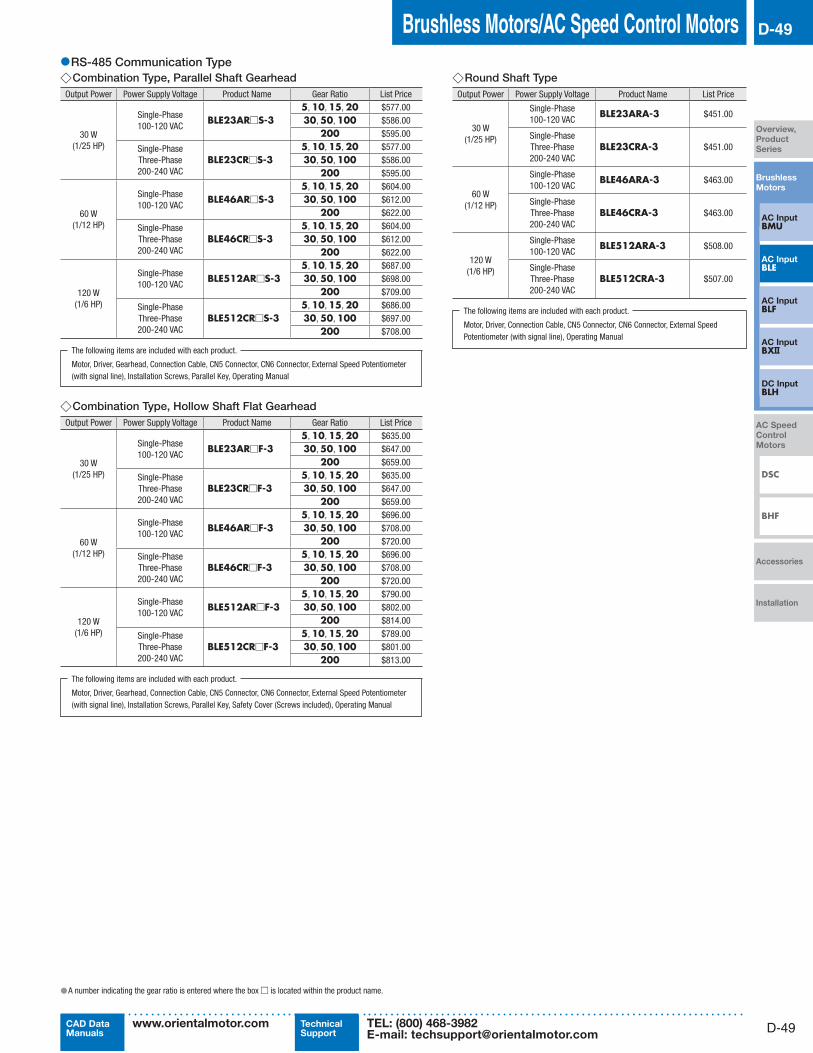
●RS-485 Communication Type ◇Combination Type, Parallel Shaft Gearhead
Output Power Power Supply Voltage Product Name Gear Ratio List Price
30 W(1/25 HP)
Single-Phase100-120 VAC
BLE23AR□S-35, 10, 15, 20 $577.0030, 50, 100 $586.00
200 $595.00
Single-PhaseThree-Phase200-240 VAC
BLE23CR□S-35, 10, 15, 20 $577.0030, 50, 100 $586.00
200 $595.00
60 W(1/12 HP)
Single-Phase100-120 VAC
BLE46AR□S-35, 10, 15, 20 $604.0030, 50, 100 $612.00
200 $622.00
Single-PhaseThree-Phase200-240 VAC
BLE46CR□S-35, 10, 15, 20 $604.0030, 50, 100 $612.00
200 $622.00
120 W(1/6 HP)
Single-Phase100-120 VAC
BLE512AR□S-35, 10, 15, 20 $687.0030, 50, 100 $698.00
200 $709.00
Single-PhaseThree-Phase200-240 VAC
BLE512CR□S-35, 10, 15, 20 $686.0030, 50, 100 $697.00
200 $708.00
The following items are included with each product.
Motor, Driver, Gearhead, Connection Cable, CN5 Connector, CN6 Connector, External Speed Potentiometer (with signal line), Installation Screws, Parallel Key, Operating Manual
◇Combination Type, Hollow Shaft Flat GearheadOutput Power Power Supply Voltage Product Name Gear Ratio List Price
30 W(1/25 HP)
Single-Phase100-120 VAC
BLE23AR□F-35, 10, 15, 20 $635.0030, 50, 100 $647.00
200 $659.00
Single-PhaseThree-Phase200-240 VAC
BLE23CR□F-35, 10, 15, 20 $635.0030, 50, 100 $647.00
200 $659.00
60 W(1/12 HP)
Single-Phase100-120 VAC
BLE46AR□F-35, 10, 15, 20 $696.0030, 50, 100 $708.00
200 $720.00
Single-PhaseThree-Phase200-240 VAC
BLE46CR□F-35, 10, 15, 20 $696.0030, 50, 100 $708.00
200 $720.00
120 W(1/6 HP)
Single-Phase100-120 VAC
BLE512AR□F-35, 10, 15, 20 $790.0030, 50, 100 $802.00
200 $814.00
Single-PhaseThree-Phase200-240 VAC
BLE512CR□F-35, 10, 15, 20 $789.0030, 50, 100 $801.00
200 $813.00
The following items are included with each product.
Motor, Driver, Gearhead, Connection Cable, CN5 Connector, CN6 Connector, External Speed Potentiometer (with signal line), Installation Screws, Parallel Key, Safety Cover (Screws included), Operating Manual
◇Round Shaft Type Output Power Power Supply Voltage Product Name List Price
30 W(1/25 HP)
Single-Phase100-120 VAC
BLE23ARA-3 $451.00
Single-PhaseThree-Phase200-240 VAC
BLE23CRA-3 $451.00
60 W(1/12 HP)
Single-Phase100-120 VAC
BLE46ARA-3 $463.00
Single-PhaseThree-Phase200-240 VAC
BLE46CRA-3 $463.00
120 W(1/6 HP)
Single-Phase100-120 VAC
BLE512ARA-3 $508.00
Single-PhaseThree-Phase200-240 VAC
BLE512CRA-3 $507.00
The following items are included with each product.
Motor, Driver, Connection Cable, CN5 Connector, CN6 Connector, External Speed Potentiometer (with signal line), Operating Manual
●A number indicating the gear ratio is entered where the box □ is located within the product name.

D-50
D-50 Brushless Motors/BLE Series
ORIENTAL MOTOR GENERAL CATALOG 2015/2016
Page Features D-42 / System Configuration D-45 / Product Line D-46 / Specifications D-51 / Characteristics D-54
Dimensions D-59 / Connection and Operation D-70 / Motor and Driver Combinations D-79
Standard Type
RS-485
Communication
Type
●A number indicating the gear ratio is entered where the box □ is located within the product name.
●RS-485 Communication Type with Electromagnetic Brake ◇Combination Type, Parallel Shaft Gearhead
Output Power Power Supply Voltage Product Name Gear Ratio List Price
30 W(1/25 HP)
Single-Phase100-120 VAC
BLE23AMR□S-35, 10, 15, 20 $757.0030, 50, 100 $766.00
200 $775.00
Single-PhaseThree-Phase200-240 VAC
BLE23CMR□S-35, 10, 15, 20 $757.0030, 50, 100 $766.00
200 $775.00
60 W(1/12 HP)
Single-Phase100-120 VAC
BLE46AMR□S-35, 10, 15, 20 $784.0030, 50, 100 $792.00
200 $802.00
Single-PhaseThree-Phase200-240 VAC
BLE46CMR□S-35, 10, 15, 20 $784.0030, 50, 100 $792.00
200 $802.00
120 W(1/6 HP)
Single-Phase100-120 VAC
BLE512AMR□S-35, 10, 15, 20 $926.0030, 50, 100 $938.00
200 $948.00
Single-PhaseThree-Phase200-240 VAC
BLE512CMR□S-35, 10, 15, 20 $927.0030, 50, 100 $938.00
200 $949.00
The following items are included with each product.
Motor, Driver, Gearhead, Connection Cable, CN5 Connector, CN6 Connector, External Speed Potentiometer (with signal line), Installation Screws, Parallel Key, Operating Manual
◇Combination Type, Hollow Shaft Flat GearheadOutput Power Power Supply Voltage Product Name Gear Ratio List Price
30 W(1/25 HP)
Single-Phase100-120 VAC
BLE23AMR□F-35, 10, 15, 20 $815.0030, 50, 100 $827.00
200 $839.00
Single-PhaseThree-Phase200-240 VAC
BLE23CMR□F-35, 10, 15, 20 $815.0030, 50, 100 $827.00
200 $839.00
60 W(1/12 HP)
Single-Phase100-120 VAC
BLE46AMR□F-35, 10, 15, 20 $876.0030, 50, 100 $888.00
200 $900.00
Single-PhaseThree-Phase200-240 VAC
BLE46CMR□F-35, 10, 15, 20 $876.0030, 50, 100 $888.00
200 $900.00
120 W(1/6 HP)
Single-Phase100-120 VAC
BLE512AMR□F-35, 10, 15, 20 $1,029.0030, 50, 100 $1,041.00
200 $1,053.00
Single-PhaseThree-Phase200-240 VAC
BLE512CMR□F-35, 10, 15, 20 $1,030.0030, 50, 100 $1,042.00
200 $1,054.00
The following items are included with each product.
Motor, Driver, Gearhead, Connection Cable, CN5 Connector, CN6 Connector, External Speed Potentiometer (with signal line), Installation Screws, Parallel Key, Safety Cover (Screws included), Operating Manual
◇Round Shaft TypeOutput Power Power Supply Voltage Product Name List Price
30 W(1/25 HP)
Single-Phase100-120 VAC
BLE23AMRA-3 $631.00
Single-PhaseThree-Phase200-240 VAC
BLE23CMRA-3 $631.00
60 W(1/12 HP)
Single-Phase100-120 VAC
BLE46AMRA-3 $643.00
Single-PhaseThree-Phase200-240 VAC
BLE46CMRA-3 $643.00
120 W(1/6 HP)
Single-Phase100-120 VAC
BLE512AMRA-3 $748.00
Single-PhaseThree-Phase200-240 VAC
BLE512CMRA-3 $747.00
The following items are included with each product.
Motor, Driver, Connection Cable, CN5 Connector, CN6 Connector, External Speed Potentiometer (with signal line), Operating Manual

D-51
Brushless Motors/AC Speed Control Motors D-51
Brushless
Motors
Overview,
Product
Series
AC InputBMU
AC Input BLE
AC Input BLF
AC Input BX
DC Input BLH
DSC
BHF
AC Speed
Control
Motors
Accessories
Installation
CAD DataManuals
www.orientalmotor.com Technical Support
TEL: (800) 468-3982E-mail: [email protected]
■Specifications
●Standard Type and RS-485 Communication Type ◇30 W (1/25 HP) Standard Type: / RS-485 Communication Type:
Product Name
Standard Type, Combination Type BLE23A□ ■■ -3 BLE23C□ ■■-3 BLE23S□ ■■ -3Standard Type, Round Shaft Type BLE23AA-3 BLE23CA-3 BLE23SA-3RS-485 Communication Type, Combination Type BLE23AR□ ■■ -3 BLE23CR□ ■■ -3RS-485 Communication Type, Round Shaft Type BLE23ARA-3 BLE23CRA-3
Rated Output Power (Continuous) W (HP) 30 (1/25)
Power Supply Input
Rated Voltage V Single-Phase 100-120 Single-Phase 200-240 Three-Phase 200-240Permissible Voltage Range −15∼+10%Rated Frequency Hz 50/60Permissible Frequency Range ±5%Rated Input Current A 1.3 0.8 0.45Maximum Input Current A 3.5 2.1 1.2
Control Power Supply✽1
Voltage 24 VDCPermissible Voltage Range −15∼+20%
Rated Torque N·m (oz-in) 0.1 (14.2)Maximum Instantaneous Torque✽2 N·m (oz-in) 0.2 (28)Rated Speed r/min 3000
Speed Control Range r/min 100∼4000 (Analog setting) 80∼4000 (Setting in 1 r/min increments during digital setting)✽3
Round Shaft Type Permissible Inertia J: ×10-4 kg·m2 (oz-in2) 1.8 (9.8)Rotor Inertia J: ×10-4 kg·m2 (oz-in2) 0.087 (0.48)
Speed Regulation
Load ±0.5% (±0.2%)✽3 or less: Conditions 0∼rated torque, rated speed, rated voltage, normal ambient temperatureVoltage ±0.5% (±0.2%)✽3 or less: Conditions Rated voltage −15∼+10%, rated speed, no load, normal ambient temperature
Temperature±0.5% (±0.2%)✽3 or less: Conditions Operating ambient temperature 0∼+50˚C (+32∼+122˚F), rated speed, no load, rated voltage
◇60 W (1/12 HP) Standard Type: / RS-485 Communication Type:
Product Name
Standard Type, Combination Type BLE46A□ ■■ -3 BLE46C□ ■■ -3 BLE46S□ ■■ -3Standard Type, Round Shaft Type BLE46AA-3 BLE46CA-3 BLE46SA-3RS-485 Communication Type, Combination Type BLE46AR□ ■■ -3 BLE46CR□ ■■ -3RS-485 Communication Type, Round Shaft Type BLE46ARA-3 BLE46CRA-3
Rated Output Power (Continuous) W (HP) 60 (1/12)
Power Supply Input
Rated Voltage V Single-Phase 100-120 Single-Phase 200-240 Three-Phase 200-240Permissible Voltage Range −15∼+10%Rated Frequency Hz 50/60Permissible Frequency Range ±5%Rated Input Current A 2.0 1.2 0.7 Maximum Input Current A 4.5 2.6 1.5
Control Power Supply✽1
Voltage 24 VDCPermissible Voltage Range −15∼+20%
Rated Torque N·m (oz-in) 0.2 (28)Maximum Instantaneous Torque✽2 N·m (oz-in) 0.4 (56)Rated Speed r/min 3000
Speed Control Range r/min 100∼4000 (Analog setting) 80∼4000 (Setting in 1 r/min increments during digital setting)✽3
Round Shaft Type Permissible Inertia J: ×10-4 kg·m2 (oz-in2) 3.75 (21)Rotor Inertia J: ×10-4 kg·m2 (oz-in2) 0.24 (1.31)
Speed Regulation
Load ±0.5% (±0.2%)✽3 or less: Conditions 0∼rated torque, rated speed, rated voltage, normal ambient temperatureVoltage ±0.5% (±0.2%)✽3 or less: Conditions Rated voltage −15∼+10%, rated speed, no load, normal ambient temperature
Temperature±0.5% (±0.2%)✽3 or less: Conditions Operating ambient temperature 0∼+50˚C (+32∼+122˚F), rated speed, no load, rated voltage
✽1 Please provide for the RS-485 communication type.
✽2 The maximum instantaneous torque can be used for up to approximately five seconds.
✽3 These specifications apply when the RS-485 communication is used with either the OPX-2A or MEXE02. ●The values in the table are characteristics for the motor only.
●A number indicating the gear ratio is entered where the box □ is located within the product name.Either S or F indicating the type of gearhead is entered where the box ■■ is located within the product name.

D-52
D-52 Brushless Motors/BLE Series
ORIENTAL MOTOR GENERAL CATALOG 2015/2016
Page Features D-42 / System Configuration D-45 / Product Line D-46 / Specifications D-51 / Characteristics D-54
Dimensions D-59 / Connection and Operation D-70 / Motor and Driver Combinations D-79
Standard Type
RS-485
Communication
Type
◇120 W (1/6 HP) Standard Type: / RS-485 Communication Type:
Product Name
Standard Type, Combination Type BLE512A□ ■■ -3 BLE512C□ ■■-3 BLE512S□ ■■ -3Standard Type, Round Shaft Type BLE512AA-3 BLE512CA-3 BLE512SA-3RS-485 Communication Type, Combination Type BLE512AR□ ■■-3 BLE512CR□ ■■ -3RS-485 Communication Type, Round Shaft Type BLE512ARA-3 BLE512CRA-3
Rated Output Power (Continuous) W (HP) 120 (1/6)
Power Supply Input
Rated Voltage V Single-Phase 100-120 Single-Phase 200-240 Three-Phase 200-240Permissible Voltage Range −15∼+10%Rated Frequency Hz 50/60Permissible Frequency Range ±5%Rated Input Current A 3.3 2.0 1.2 Maximum Input Current A 8.2 4.4 2.5
Control Power Supply✽1
Voltage 24 VDCPermissible Voltage Range −15∼+20%
Rated Torque N·m (oz-in) 0.4 (56)Maximum Instantaneous Torque✽2 N·m (oz-in) 0.8 (113)Rated Speed r/min 3000
Speed Control Range r/min 100∼4000 (Analog setting) 80∼4000 (Setting in 1 r/min increments during digital setting)✽3
Round Shaft Type Permissible Inertia J: ×10-4 kg·m2 (oz-in2) 5.6 (31)Rotor Inertia J: ×10-4 kg·m2 (oz-in2) 0.61 (3.3)
Speed Regulation
Load ±0.5% (±0.2%)✽3 or less: Conditions 0∼rated torque, rated speed, rated voltage, normal ambient temperature
Voltage±0.5% (±0.2%)✽3 or less: Conditions Rated voltage −15∼+10%, rated speed, no load, normal ambient temperature
Temperature±0.5% (±0.2%)✽3 or less: Conditions Operating ambient temperature 0∼+50˚C (+32∼+122˚F), rated speed, no load, rated voltage
●Standard Type with Electromagnetic Brake and RS-485 Communication Type with Electromagnetic Brake ◇30 W (1/25 HP) Standard Type: / RS-485 Communication Type:
Product Name
Standard Type, Combination Type BLE23AM□ ■■ -3 BLE23CM□ ■■-3 BLE23SM□ ■■ -3Standard Type, Round Shaft Type BLE23AMA-3 BLE23CMA-3 BLE23SMA-3RS-485 Communication Type, Combination Type BLE23AMR□ ■■ -3 BLE23CMR□ ■■ -3RS-485 Communication Type, Round Shaft Type BLE23AMRA-3 BLE23CMRA-3
Rated Output Power (Continuous) W (HP) 30 (1/25)
Power Supply Input
Rated Voltage V Single-Phase 100-120 Single-Phase 200-240 Three-Phase 200-240Permissible Voltage Range −15∼+10%Rated Frequency Hz 50/60Permissible Frequency Range ±5%Rated Input Current A 1.3 0.8 0.45Maximum Input Current A 3.5 2.1 1.2
Control Power Supply✽1
Voltage 24 VDCPermissible Voltage Range −15∼+20%
Rated Torque N·m (oz-in) 0.1 (14.2)Maximum Instantaneous Torque✽2 N·m (oz-in) 0.2 (28)Rated Speed r/min 3000
Speed Control Range r/min 100∼4000 (Analog setting) 80∼4000 (Setting in 1 r/min increments during digital setting)✽3
Round Shaft Type Permissible Inertia J: ×10-4 kg·m2 (oz-in2) 1.8 (9.8)Rotor Inertia J: ×10-4 kg·m2 (oz-in2) 0.087 (0.48)
Speed Regulation
Load ±0.5% (±0.2%)✽3 or less: Conditions 0∼rated torque, rated speed, rated voltage, normal ambient temperature
Voltage±0.5% (±0.2%)✽3 or less: Conditions Rated voltage −15∼+10%, rated speed, no load, normal ambient temperature
Temperature±0.5% (±0.2%)✽3 or less: Conditions Operating ambient temperature 0∼+50˚C (+32∼+122˚F), rated speed, no load, rated voltage
Gravitational Operation Capability
Continuous Regenerative Power W (HP) 100 (1/8)Instantaneous Regenerative Power W (HP) 240 (1/3)Applicable Regeneration Unit✽4 EPRC-400P
Electromagnetic Brake✽5 Brake Type Power off activated type, automatically controlled by the driverStatic Friction Torque N·m (oz-in) 0.1 (14.2)
✽1 Please provide for the RS-485 communication type.
✽2 The maximum instantaneous torque can be used for up to approximately five seconds.
✽3 These specifications apply when the RS-485 communication is used with either the OPX-2A or MEXE02.
✽4 Install the regeneration unit in a place that has the same heat radiation capability as the heat sink [material: aluminum, 350×350 mm (13.8×13.8 in.), 3 mm (0.12 in.) thick].
✽5 Do not start or stop the motor by turning the power supply ON/OFF, as this will cause the electromagnetic brake to wear abnormally. ●The values in the table are characteristics for the motor only.
●A number indicating the gear ratio is entered where the box □ is located within the product name.Either S or F indicating the type of gearhead is entered where the box ■■ is located within the product name.

D-53
Brushless Motors/AC Speed Control Motors D-53
Brushless
Motors
Overview,
Product
Series
AC InputBMU
AC Input BLE
AC Input BLF
AC Input BX
DC Input BLH
DSC
BHF
AC Speed
Control
Motors
Accessories
Installation
CAD DataManuals
www.orientalmotor.com Technical Support
TEL: (800) 468-3982E-mail: [email protected]
◇60 W (1/12 HP) Standard Type: / RS-485 Communication Type:
Product Name
Standard Type, Combination Type BLE46AM□ ■■ -3 BLE46CM□ ■■ -3 BLE46SM□ ■■ -3Standard Type, Round Shaft Type BLE46AMA-3 BLE46CMA-3 BLE46SMA-3RS-485 Communication Type, Combination Type BLE46AMR□ ■■ -3 BLE46CMR□ ■■ -3RS-485 Communication Type, Round Shaft Type BLE46AMRA-3 BLE46CMRA-3
Rated Output Power (Continuous) W (HP) 60 (1/12)
Power Supply Input
Rated Voltage V Single-Phase 100-120 Single-Phase 200-240 Three-Phase 200-240Permissible Voltage Range −15∼+10%Rated Frequency Hz 50/60Permissible Frequency Range ±5%Rated Input Current A 2.0 1.2 0.7
Maximum Input Current A 4.5 2.6 1.5
Control Power Supply✽1
Voltage 24 VDCPermissible Voltage Range −15∼+20%
Rated Torque N·m (oz-in) 0.2 (28)Maximum Instantaneous Torque✽2 N·m (oz-in) 0.4 (56)Rated Speed r/min 3000
Speed Control Range r/min 100∼4000 (Analog setting) 80∼4000 (Setting in 1 r/min increments during digital setting)✽3
Round Shaft Type Permissible Inertia J: ×10-4 kg·m2 (oz-in2) 3.75 (21)Rotor Inertia J: ×10-4 kg·m2 (oz-in2) 0.24 (1.31)
Speed Regulation
Load ±0.5% (±0.2%)✽3 or less: Conditions 0∼rated torque, rated speed, rated voltage, normal ambient temperature
Voltage±0.5% (±0.2%)✽3 or less: Conditions Rated voltage −15∼+10%, rated speed, no load, normal ambient temperature
Temperature±0.5% (±0.2%)✽3 or less: Conditions Operating ambient temperature 0∼+50˚C (+32∼+122˚F), rated speed, no load, rated voltage
Gravitational Operation Capability
Continuous Regenerative Power W (HP) 100 (1/8)Instantaneous Regenerative Power W (HP) 240 (1/3)Applicable Regeneration Unit✽4 EPRC-400P
Electromagnetic Brake✽5 Brake Type Power off activated type, automatically controlled by the driverStatic Friction Torque N·m (oz-in) 0.2 (28)
◇120 W (1/6 HP) Standard Type: / RS-485 Communication Type:
Product Name
Standard Type, Combination Type BLE512AM□ ■■ -3 BLE512CM□ ■■ -3 BLE512SM□ ■■-3Standard Type, Round Shaft Type BLE512AMA-3 BLE512CMA-3 BLE512SMA-3RS-485 Communication Type, Combination Type BLE512AMR□ ■■ -3 BLE512CMR□ ■■ -3RS-485 Communication Type, Round Shaft Type BLE512AMRA-3 BLE512CMRA-3
Rated Output Power (Continuous) W (HP) 120 (1/6)
Power Supply Input
Rated Voltage V Single-Phase 100-120 Single-Phase 200-240 Three-Phase 200-240Permissible Voltage Range −15∼+10%Rated Frequency Hz 50/60Permissible Frequency Range ±5%Rated Input Current A 3.3 2.0 1.2 Maximum Input Current A 8.2 4.4 2.5
Control Power Supply✽1
Voltage 24 VDCPermissible Voltage Range −15∼+20%
Rated Torque N·m (oz-in) 0.4 (56)Maximum Instantaneous Torque✽2 N·m (oz-in) 0.8 (113)Rated Speed r/min 3000
Speed Control Range r/min 100∼4000 (Analog setting) 80∼4000 (Setting in 1 r/min increments during digital setting)✽3
Round Shaft Type Permissible Inertia J: ×10-4 kg·m2 (oz-in2) 5.6 (31)Rotor Inertia J: ×10-4 kg·m2 (oz-in2) 0.61 (3.3)
Speed Regulation
Load ±0.5% (±0.2%)✽3 or less: Conditions 0∼rated torque, rated speed, rated voltage, normal ambient temperature
Voltage±0.5% (±0.2%)✽3 or less: Conditions Rated voltage −15∼+10%, rated speed, no load, normal ambient temperature
Temperature±0.5% (±0.2%)✽3 or less: Conditions Operating ambient temperature 0∼+50˚C (+32∼+122˚F), rated speed, no load, rated voltage
Gravitational Operation Capability
Continuous Regenerative Power W (HP) 100 (1/8)Instantaneous Regenerative Power W (HP) 240 (1/3)Applicable Regeneration Unit✽4 EPRC-400P
Electromagnetic Brake✽5 Brake Type Power off activated type, automatically controlled by the driverStatic Friction Torque N·m (oz-in) 0.4 (56)
✽1 Please provide for the RS-485 communication type.
✽2 The maximum instantaneous torque can be used for up to approximately five seconds.
✽3 These specifications apply when the RS-485 communication is used with either the OPX-2A or MEXE02.
✽4 Install the regeneration unit in a place that has the same heat radiation capability as the heat sink [material: aluminum, 350×350 mm (13.8×13.8 in.), 3 mm (0.12 in.) thick].
✽5 Do not start or stop the motor by turning the power supply ON/OFF, as this will cause the electromagnetic brake to wear abnormally. ●The values in the table are characteristics for the motor only.
●A number indicating the gear ratio is entered where the box □ is located within the product name.Either S or F indicating the type of gearhead is entered where the box ■■ is located within the product name.

D-54
D-54 Brushless Motors/BLE Series
ORIENTAL MOTOR GENERAL CATALOG 2015/2016
Page Features D-42 / System Configuration D-45 / Product Line D-46 / Specifications D-51 / Characteristics D-54
Dimensions D-59 / Connection and Operation D-70 / Motor and Driver Combinations D-79
Standard Type
RS-485
Communication
Type
■Vertical Operation (Gravitational operation)
The BLE Series achieves stable speed control during gravitational operation.During vertical operation, shown in the figure to the right, normally an external force causes the motor to rotate and function as a power generator. If this energy is applied to the driver, an error will occur.The accessory regeneration unit (sold separately) can convert regenerative energy into thermal energy for dissipation. Use the accessory regeneration unit when using the motor for vertical operation or when braking a big inertial load quickly.
Regeneration Unit Product Name : EPRC-400PContinuous Regenerative Power : 100 W (1/8 HP)Instantaneous Regenerative Power: 240 W (1/3 HP)
● Install the regeneration unit in a place that has the same heat radiation capability as the heat sink [material: aluminum, 350×350 mm (13.8×13.8 in.), 3 mm (0.12 in.) thick].
Note ● If the motor is used in a lift, the load may drop if the load exceeds the motor's rating or if the torque limit is set to a small value through RS-485 communication, OPX-2A or MEXE02. Even if the load is within the motor's rating, depending on the load conditions, reversing may occur momentarily during startup or shutdown.
● Regenerative PowerThe regenerative power can be estimated using the formula below. Use the calculated value as a reference. Regenerative Power (W) = 0.1047 × TL [N·m] × N [r/min] TL : Load torque N : Speed
●Use the electromagnetic brake type for gravitational operation.
●Gravitational Operation Capability
WLoad
0
-0.05
-0.1
-0.15
-0.2
-0.25
-0.3
-0.35
-0.4
-0.45
0 1000 2000 3000 4000
BLE23
BLE46
BLE512
-10
-20
-30
-40
-50
-60
0
Gravitational Operation Capability
Speed [r/min]
Torq
ue [N
·m]
Torq
ue [o
z-in
]
●Gravitational operation exceeding the range of continuous regeneration capability will trigger the built-in thermal protector [150˚C (302˚F)].
■Speed - Torque Characteristics
Continuous Duty Region: Continuous operation is possible in this region.Limited Duty Region : This region is used primarily when accelerating. When a load that exceeds the rated torque is applied continuously for
approximately 5 seconds, overload protection is activated and the motor coasts to a stop.
●30 W (1/25 HP) ●60 W (1/12 HP)
40000
1000 2000 3000
0.0750.1
0.228
14.210.6
0100 (80)✽
[ N· m
]
[oz-
in]
Continuous Duty Region
Limited Duty RegionRated Torque
Maximum Instantaneous Torque
Speed [r/min]
Torq
ue
40001000 2000 3000100 (80)✽
0.2
0.4
0.15
0
[ N· m
]
56
2821
0
[oz-
in]
Continuous Duty Region
Limited Duty Region
Maximum Instantaneous Torque
Speed [r/min]
Torq
ue
Rated Torque
●120 W (1/6 HP)
40001000 2000 3000100 (80)✽
0.4
0.8
0.3
0
[ N· m
]
113
5642
0
[oz-
in]
Continuous Duty Region
Limited Duty RegionRated Torque
Maximum Instantaneous Torque
Speed [r/min]
Torq
ue
✽Values in parentheses apply when RS-485 communication, OPX-2A or MEXE02 is used. ●For combination types, the values are for the motor only.

D-55
Brushless Motors/AC Speed Control Motors D-55
Brushless
Motors
Overview,
Product
Series
AC InputBMU
AC Input BLE
AC Input BLF
AC Input BX
DC Input BLH
DSC
BHF
AC Speed
Control
Motors
Accessories
Installation
CAD DataManuals
www.orientalmotor.com Technical Support
TEL: (800) 468-3982E-mail: [email protected]
■Common Specifications (Standard type)
● Standard Product : These specifications apply when the basic motor and driver package is used. ● Extended Functions: These specifications apply when control module (OPX-2A) or data setting software (MEXE02) is used.
Item Standard Product Extended Functions
Speed Setting Methods
Select one of the following methods.·Set using the internal speed potentiometer·Set using an external speed potentiometer (included): PAVR-20KZ (20 kΩ, 1/4 W)·Set using external DC voltage: 0∼5 VDC, or 0∼10 VDC, 1 mA min.
Select one of the following methods.·Digital setting (OPX-2A or MEXE02)·Set using the internal speed potentiometer·Set using an external speed potentiometer (included): PAVR-20KZ (20 kΩ, 1/4 W)·Set using external DC voltage: 0∼5 VDC, or 0∼10 VDC, 1 mA min.
Acceleration/Deceleration Time
Set using acceleration and deceleration time potentiometer:0.2∼15 sec. (3000 r/min at no load)
Select one of the following methods.· Digital setting (OPX-2A or MEXE02): 0.2∼15 sec. (time until setting speed is achieved)·Set using acceleration and deceleration time potentiometer: 0.2∼15 sec. (3000 r/min at no load)
Multi-Speed Setting Methods
2 Speeds: 1 speed set by the internal speed potentiometer and 1 speed set by the external speed potentiometer (20 kΩ, 1/4 W) or external DC voltage (0∼5 VDC or 0∼10 VDC)
Select one of the following methods.·8 Speeds: 8 speeds set by digital setting (OPX-2A or MEXE02)·8 Speeds: 6 speeds set by digital setting (OPX-2A or MEXE02) and 2 speeds set by analog setting✽
Input Signals
Photocoupler Input Input Resistance: 5.1 kΩOperated by Internal Power Supply: 17 VDC±10%Connectable External DC Power Supply: 24 VDC −15∼+20% Current 100 mA min.
Forward input (FWD), Reverse input (REV), Stop mode selection input (STOP-MODE), Speed setting selection input (M0), Alarm reset input (ALARM-RESET), Electromagnetic brake release input (MB-FREE), Regeneration unit thermal input (TH)
Arbitrary signal assignment to general purpose input X0∼X6 (7 points) is possibleForward input (FWD), Reverse input (REV), Stop mode selection input (STOP-MODE), Speed setting selection input (M0, M1, M2), Alarm reset input (ALARM-RESET), Electromagnetic brake release input (MB-FREE), Regeneration unit thermal input (TH), External error signal (EXT-ERROR)
Output Signals
Open-collector outputExternal Use Condition: Voltage control 4.5∼30.0 VDC Current 40 mA max.Speed Output: 5 mA min.
Speed output (SPEED-OUT), Alarm output 1 (ALARM-OUT 1)
Arbitrary signal assignment to general purpose output Y0, Y1 (2 points) is possibleSpeed output (SPEED-OUT), Alarm output 1 (ALARM-OUT1), Motor running output (MOVE), Speed attainment output (VA), Alarm output 2 (ALARM-OUT2), Warning output (WNG), Torque limit output (TLC)
Protective FunctionWhen the following protective functions are activated, the motor will coast to a stop, and the ALARM output will be turned off.Overload, Sensor error, Initial sensor error, Overvoltage, Undervoltage, Overspeed, Overcurrent, EEPROM error, Regeneration unit overheat, External stop, Initial operation inhibition, Main circuit output error
Maximum Extension Distance
Motor and Driver Distance: 20.5 m (67.2 ft.) (when a connection cable is used)
Time Rating Continuous
✽One speed set by the internal speed potentiometer and one speed set by the external speed potentiometer (20 kΩ, 1/4 W) or external DC voltage (0∼5 VDC or 0∼10 VDC).
■Common Specifications (RS-485 communication type)
● Analog Speed Setting: Speed setting by the external speed potentiometer or external DC voltage ● Digital Speed Setting : Speed setting through RS-485 communication with the OPX-2A or MEXE02
Item Specifi cations
Speed Setting MethodsDigital Setting
· RS-485 Communication · Control Module (OPX-2A) · Data Setting Software (MEXE02)
Analog Setting · External speed potentiometer (included): PAVR-20KZ (20 kΩ, 1/4 W) · External DC voltage: 0∼10 VDC, 1 mA min.
Acceleration/Deceleration Time Digital Setting0.2∼15 sec.Analog Speed Setting: Time to change from standstill to the rated speedDigital Speed Setting: Time to change from the current speed to the set speed
Multi-Speed Setting Methods Digital Setting
Select one of the following methods. · 16 Speeds: 16 speeds set by digital setting (RS-485 communication, OPX-2A or MEXE02) · 16 Speeds: 15 speeds set by digital setting (RS-485 communication, OPX-2A or MEXE02) and 1 speed set by analog setting (external
speed potentiometer or external DC voltage)
Input Signals
Photocoupler Input Input Resistance: 5.1 kΩOperated by Internal Power Supply: 24 VDC −15∼+20%Connectable External Power Supply: 24 VDC −15∼+20% 100 mA min.
Input signals can be assigned to input terminals IN0∼IN6.For the input signals that can be assigned, refer to page D-75.
Output Signals
Open-collector outputExternal power supply: 4.5∼30 VDC Speed output: 5∼40 mA Other outputs: 40 mA max.
Output signals can be assigned to output terminals OUT0 and OUT1.For the output signals that can be assigned, refer to page D-75.
Protective Function
When the following protective functions are activated, the motor will coast to a stop, and the ALARM output will be turned off.Overload, Sensor error, Initial sensor error, Overvoltage, Undervoltage, Overspeed, Overcurrent, EEPROM error, Regeneration unit overheat, External stop, Initial operation inhibition, Network bus error, Communication switch setting error, RS-485 communication error, RS-485 communication timeout, Network converter error, Main power supply off, Main circuit output error
Maximum Extension Distance Motor and Driver Distance: 20.5 m (67.2 ft.) (when a connection cable is used)Time Rating Continuous

D-56
D-56 Brushless Motors/BLE Series
ORIENTAL MOTOR GENERAL CATALOG 2015/2016
Page Features D-42 / System Configuration D-45 / Product Line D-46 / Specifications D-51 / Characteristics D-54
Dimensions D-59 / Connection and Operation D-70 / Motor and Driver Combinations D-79
Standard Type
RS-485
Communication
Type
■RS-485 Communication Specifications (RS-485 communication type)
Protocol Modbus Protocol (Modbus RTU mode)
Electrical CharacteristicsComplies with EIA-485.Use twisted-pair cables (TIA/EIA-568B CAT5e or better recommended). The maximum total extension length is 50 m (164 ft.).
Transmission/Reception Mode Half duplexBaud Rate 9600 bps, 19200 bps, 38400 bps, 57600 bps, 115200 bpsPhysical Layer Start-stop synchronization (data: 8 bits, stop bit: 1 bit or 2 bits, parity: none, even, or odd)Connection Type Up to 31 units can be connected to a single programmable controller (master unit).
■Torque Limiting Function
A limit on the output torque of the motor can be set by using a control module (OPX-2A), data setting software (MEXE02), or RS-485 communication.
Item Specifi cations
Torque Limiting Setting Methods
Select one of the following methods.·Digital Independent Setting: Torque limiting values can be set separately for 8 data sets (standard type) and 16 data sets (RS-485 communication type).· External Analog Common Setting: A torque limiting value can be set to all data sets at once with an external speed potentiometer PAVR-20KZ (20 kΩ, 1/4 W) or with external DC voltage (0∼5 VDC or 0∼10 VDC).
The same torque limiting value applies to all operation data.
Torque Limiting Setting Range
Assuming that the rated torque of the motor is 100%, torque limiting values can be set in the following ranges (initial value 200%).·Digital Setting: 0∼200% (set in 1% increments)·External Analog Common Setting: Set from 0∼200% with an external speed potentiometer PAVR-20KZ (20 kΩ, 1/4 W) or with external DC voltage (0∼5 VDC
or 0∼10 VDC)
Note ●An error up to a maximum of approximately ±20% (at rated torque and rated speed) may occur between the setting value and generated torque due to the setting speed, power supply voltage and motor cable extension length.
■General Specifications
Item Motor Driver
Insulation Resistance
100 MΩ or more when 500 VDC megger is applied between the windings and the case after continuous operation under normal ambient temperature and humidity.
100 MΩ or more when a 500 VDC megger is applied between the power supply terminal and the protective earth terminal and between the power supply terminal and the I/O signal terminal after continuous operation under normal ambient temperature and humidity.
Dielectric Strength
Sufficient to withstand 1.5 kVAC at 50 Hz applied between the windings and the case for 1 minute after continuous operation under normal ambient temperature and humidity.
Sufficient to withstand 1834 VAC at 50 Hz applied between the power supply terminal and the protective earth terminal and with application of 3 kVAC at 50 Hz between the power supply terminal and the I/O terminal for 1 minute after continuous operation under normal ambient temperature and humidity.
Temperature Rise
Temperature rise of the windings and the case are 50˚C (90˚F) or less, and 40˚C (72˚F) or less✽1 respectively measured by the thermocouple method after continuous operation under normal ambient temperature and humidity.
Temperature rise of the heat radiation plate is 50˚C (90˚F) or less measured by the thermocouple method after continuous operation under normal ambient temperature and humidity.
OperatingEnvironment
Ambient Temperature 0∼+50˚C (+32∼+122˚F) (non-freezing)Ambient Humidity 85% or less (non-condensing) Altitude Up to 1000 m (3300 ft.) above sea levelAtmosphere No corrosive gases or dust. Cannot be used in a radioactive area, magnetic field, vacuum or other special environment
Vibration
Not subject to continuous vibration or excessive impactIn conformance with JIS C 60068-2-6, "Sine-wave vibration test method"Frequency range: 10∼55 Hz Pulsating amplitude: 0.15 mm (0.006 in.)Sweep direction: 3 directions (X, Y, Z) Number of sweeps: 20 times
Storage Condition✽2
Ambient Temperature −25∼+70˚C (−13∼+158˚F) (non-freezing) Ambient Humidity 85% or less (non-condensing) Altitude Up to 3000 m (10000 ft.) above sea level
Thermal Class UL/CSA standards: 105 (A), EN standards: 120 (E) −
Degree of ProtectionIP65 (Excluding the mounting surface of the round shaft type and connectors)
IP20
✽1 For round shaft types, please attach to the heat radiation plate (material: aluminum) of the following sizes to maintain a maximum motor case temperature of 90˚C (194˚F).30 W (1/25 HP) Standard Type: 115×115 mm (4.53×4.53 in.), 5 mm (0.20 in.) thick30 W (1/25 HP) With Electromagnetic Brake Type: 135×135 mm (5.31×5.31 in.), 5 mm (0.20 in.) thick60 W (1/12 HP) Type: 135×135 mm (5.31×5.31 in.), 5 mm (0.20 in.) thick120 W (1/6 HP) Type: 165×165 mm (6.50×6.50 in.), 5 mm (0.20 in.) thick
✽2 The storage condition applies to a short period such as a period during transportation.
Note ●Do not measure insulation resistance or perform the dielectric strength test while the motor and driver are connected.

D-57
Brushless Motors/AC Speed Control Motors D-57
Brushless
Motors
Overview,
Product
Series
AC InputBMU
AC Input BLE
AC Input BLF
AC Input BX
DC Input BLH
DSC
BHF
AC Speed
Control
Motors
Accessories
Installation
CAD DataManuals
www.orientalmotor.com Technical Support
TEL: (800) 468-3982E-mail: [email protected]
■ Permissible Torque on Combination Types
●Combination Type, Parallel Shaft Gearhead Unit: N·m (lb-in)
Product NameGear Ratio
Motor ShaftSpeed
5 10 15 20 30 50 100 200
BLE23At 100∼3000 r/min 0.45 (3.9) 0.90 (7.9) 1.4 (12.3) 1.8 (15.9) 2.6 (23) 4.3 (38) 6 (53) 6 (53)At 4000 r/min 0.34 (3.0) 0.68 (6.0) 1.0 (8.8) 1.4 (12.3) 1.9 (16.8) 3.2 (28) 5.4 (47) 5.4 (47)
BLE46At 100∼3000 r/min 0.90 (7.9) 1.8 (15.9) 2.7 (23) 3.6 (31) 5.2 (46) 8.6 (76) 16 (141) 16 (141)At 4000 r/min 0.68 (6.0) 1.4 (12.3) 2.0 (17.7) 2.7 (23) 3.9 (34) 6.5 (57) 12.9 (114) 14 (123)
BLE512At 100∼3000 r/min 1.8 (15.9) 3.6 (31) 5.4 (47) 7.2 (63) 10.3 (91) 17.2 (152) 30 (260) 30 (260)At 4000 r/min 1.4 (12.3) 2.7 (23) 4.1 (36) 5.4 (47) 7.7 (68) 12.9 (114) 25.8 (220) 27 (230)
●A colored background ( ) indicates gear shaft rotation in the same direction as the motor shaft. Others rotate in the opposite direction.
●Combination Type, Hollow Shaft Flat Gearhead Unit: N·m (lb-in)
Product NameGear Ratio
Motor ShaftSpeed
5 10 15 20 30 50 100 200
BLE23At 100∼3000 r/min 0.4 (3.5) 0.85 (7.5) 1.3 (11.5) 1.7 (15.0) 2.6 (23) 4.3 (38) 8.5 (75) 17 (150)At 4000 r/min 0.3 (2.6) 0.64 (5.6) 0.96 (8.4) 1.3 (11.5) 1.9 (16.8) 3.2 (28) 6.4 (56) 12.8 (113)
BLE46At 100∼3000 r/min 0.85 (7.5) 1.7 (15.0) 2.6 (23) 3.4 (30) 5.1 (45) 8.5 (75) 17 (150) 34 (300)At 4000 r/min 0.64 (5.6) 1.3 (11.5) 1.9 (16.8) 2.6 (23) 3.8 (33) 6.4 (56) 12.8 (113) 25.5 (220)
BLE512At 100∼3000 r/min 1.7 (15.0) 3.4 (30) 5.1 (45) 6.8 (60) 10.2 (90) 17 (150) 34 (300) 68 (600)At 4000 r/min 1.3 (11.5) 2.6 (23) 3.8 (33) 5.1 (45) 7.7 (68) 12.8 (113) 25.5 (220) 51 (450)
●The flat gearhead rotates in the opposite direction to the motor when viewed from the front face of the gearhead. It rotates in the same direction as the motor when viewed from the rear (motor mounting surface) of the gearhead.Rotation direction of hollow shaft flat gearhead ➜ Page D-195
■Output Shaft Speed of Combination Types Unit: r/min
Gear RatioMotor ShaftSpeed
5 10 15 20 30 50 100 200
100 r/min 20 10 6.7 5 3.3 2 1 0.53000 r/min 600 300 200 150 100 60 30 154000 r/min 800 400 267 200 133 80 40 20
■Permissible Radial Load and Permissible Axial Load
●Combination Type, Parallel Shaft Gearhead
Product Name Gear RatioPermissible Radial Load
Permissible Axial Load10 mm (0.39 in.) from shaft end 20 mm (0.79 in.) from shaft end
N lb. N lb. N lb.
BLE23
5At 100∼3000 r/min 100 22 150 33
40 9
At 4000 r/min 90 20 110 24
10, 15, 20At 100∼3000 r/min 150 33 200 45At 4000 r/min 130 29 170 38
30, 50, 100, 200At 100∼3000 r/min 200 45 300 67At 4000 r/min 180 40 230 51
BLE46
5At 100∼3000 r/min 200 45 250 56
100 22
At 4000 r/min 180 40 220 49
10, 15, 20At 100∼3000 r/min 300 67 350 78At 4000 r/min 270 60 330 74
30, 50, 100, 200At 100∼3000 r/min 450 101 550 123At 4000 r/min 420 94 500 112
BLE512
5At 100∼3000 r/min 300 67 400 90
150 33
At 4000 r/min 230 51 300 67
10, 15, 20At 100∼3000 r/min 400 90 500 112At 4000 r/min 370 83 430 96
30, 50, 100, 200At 100∼3000 r/min 500 112 650 146At 4000 r/min 450 101 550 123
10 mm (0.39 in.)20 mm (0.79 in.)
Distance from Output Shaft End
Axial Load
Radial Load

D-58
D-58 Brushless Motors/BLE Series
ORIENTAL MOTOR GENERAL CATALOG 2015/2016
Page Features D-42 / System Configuration D-45 / Product Line D-46 / Specifications D-51 / Characteristics D-54
Dimensions D-59 / Connection and Operation D-70 / Motor and Driver Combinations D-79
Standard Type
RS-485
Communication
Type
●Combination Type, Hollow Shaft Flat Gearhead
Product Name Gear Ratio
Permissible Radial LoadPermissible Axial Load10 mm (0.39 in.) from
mounting surface of gearhead20 mm (0.79 in.) from
mounting surface of gearheadN lb. N lb. N lb.
BLE23 5, 10
At 100∼3000 r/min 450 101 370 83
200 45At 4000 r/min 410 92 330 74
15, 20, 30, 50, 100, 200At 100∼3000 r/min 500 112 400 90At 4000 r/min 460 103 370 83
BLE465, 10
At 100∼3000 r/min 800 180 660 148
400 90At 4000 r/min 730 164 600 135
15, 20, 30, 50, 100, 200At 100∼3000 r/min 1200 270 1000 220At 4000 r/min 1100 240 910 200
BLE512
5, 10At 100∼3000 r/min 900 200 770 173
500 112
At 4000 r/min 820 184 700 157
15, 20At 100∼3000 r/min 1300 290 1110 240At 4000 r/min 1200 270 1020 220
30, 50, 100, 200At 100∼3000 r/min 1500 330 1280 280At 4000 r/min 1400 310 1200 270
●The permissible radial load can also be calculated with a formula. Calculation of permissible radial load ➜ Page D-194
Axial Load
Radial Load
10 mm (0.39 in.)20 mm (0.79 in.)
Distance from installation surface
●Round Shaft Type
Product NamePermissible Radial Load
Permissible Axial Load10 mm (0.39 in.) from shaft end 20 mm (0.79 in.) from shaft endN lb. N lb.
BLE23 80 18 100 22 The permissible axial load should not be greater than half the motor mass.
BLE46 110 24 130 29BLE512 150 33 170 38
■ Permissible Inertia J of Combination Types
●Combination Type, Parallel Shaft Gearhead Unit: ×10-4kg•m2 (oz-in2)
Gear RatioProduct Name
5 10 15 20 30 50 100 200
BLE23
12(66)
50(270)
110(600)
200(1090)
370(2000)
920(5000)
2500(13700)
5000(27000)
When instantaneous stop or instantaneous bi-directional operation is performed
1.55(8.5)
6.2(34)
14.0(77)
24.8(136)
55.8(310)
155(850)
155(850)
155(850)
BLE46
22(120)
95(520)
220(1200)
350(1910)
800(4400)
2200(12000)
6200(34000)
12000(66000)
When instantaneous stop or instantaneous bi-directional operation is performed
5.5(30)
22(120)
49.5(270)
88(480)
198(1080)
550(3000)
550(3000)
550(3000)
BLE512
45(250)
190(1040)
420(2300)
700(3800)
1600(8800)
4500(25000)
12000(66000)
25000(137000)
When instantaneous stop or instantaneous bi-directional operation is performed
25(137)
100(550)
225(1230)
400(2200)
900(4900)
2500(13700)
2500(13700)
2500(13700)
●Combination Type, Hollow Shaft Flat Gearhead Unit: ×10-4kg•m2 (oz-in2)
Gear RatioProduct Name
5 10 15 20 30 50 100 200
BLE23
12(66)
50(270)
110(600)
200(1090)
370(2000)
920(5000)
2500(13700)
5000(27000)
When instantaneous stop or instantaneous bi-directional operation is performed
1.55(8.5)
6.2(34)
14.0(77)
24.8(136)
55.8(310)
155(850)
155(850)
155(850)
BLE46
22(120)
95(520)
220(1200)
350(1910)
800(4400)
2200(12000)
6200(34000)
12000(66000)
When instantaneous stop or instantaneous bi-directional operation is performed
5.5(30)
22(120)
49.5(270)
88(480)
198(1080)
550(3000)
550(3000)
550(3000)
BLE512
45(250)
190(1040)
420(2300)
700(3800)
1600(8800)
4500(25000)
12000(66000)
25000(137000)
When instantaneous stop or instantaneous bi-directional opera-tion is performed
25(137)
100(550)
225(1230)
400(2200)
900(4900)
2500(13700)
2500(13700)
2500(13700)

D-59
Brushless Motors/AC Speed Control Motors D-59
Brushless
Motors
Overview,
Product
Series
AC InputBMU
AC Input BLE
AC Input BLF
AC Input BX
DC Input BLH
DSC
BHF
AC Speed
Control
Motors
Accessories
Installation
CAD DataManuals
www.orientalmotor.com Technical Support
TEL: (800) 468-3982E-mail: [email protected]
■Dimensions Unit = mm (in.)
● Installation screws are included with the combination type. Dimensions for installation screws ➜ Page D-194 ● For the RS-485 communication type, R is entered where the box ■ is located within the product name. ● A number indicating the gear ratio is entered where the box □ is located within the product name.
●Standard Type, RS-485 Communication Type, 30 W (1/25 HP) ◇Motor/Parallel Shaft Gearhead
Product Name Motor Product Name Gearhead Product Name Gear Ratio L Mass kg (lb.) 2D CAD
BLE23A■□S-3BLE23C■□S-3BLE23S□S-3
BLEM23-GFS GFS2G□
5∼20 34 (1.34)1.1 (2.4)
A694A30∼100 38 (1.50) A694B
200 43 (1.69) A694C
8 (0.31)
60 ( 2
.36)
□60
31 (1.22)
A
254
A
2 (0.08) 50 (1.97) L 32±1
10±
0.5
( 0.3
9±0.
02)
ϕ70±0.5
25450 (18)28.5 (1.12)
9.5
( 0.3
7)
11 ( 0
.43)
(1.26±0.04)
(0.98)
ϕ10
0−
0.01
5 (ϕ
0.39
37−
0.00
06)
0
ϕ24
(ϕ0.
94)
( □2.
36)
(1)
(0.984±0.008)
A−A
4−0.
03 0
0
4+0.040
0
0 2.5+
0.1 00
(0.1575+0.0016) ( 0.09
8+0.
004 )
( 0.15
75−
0.00
12)
25±0.2 4−0.030
(0.1575−0.0012)0(ϕ2.76±0.02)
(0.16)
Housing: 5557-06R-210 (MOLEX)
Housing: 43025-0600 (MOLEX)Motor Cable ϕ9 (ϕ0.35)Protective Earth
Terminal M4
◇Key and Key Slot (Included)
4×ϕ4.5 (ϕ0.177) Thru
◇Motor/Hollow Shaft Flat GearheadBLE23A■□F-3, BLE23C■□F-3, BLE23S□F-3Motor: BLEM23-GFSGearhead: GFS2G□FRMass: 1.4 kg (3.1 lb.)
A695
ϕ12
0
+0.
027
ϕ12
.5 0+
0.11
( ϕ0.
4724
0
) +
0.00
11
( ϕ0.
4921
0
)+
0.00
43
ϕ70±0.5
4 0 +0.040
13.8
( 0.5
4)31
60 ( 2
.36)
120.
5 ( 4
.74)
11 (0.43)
60 (2.36)
49 (1.93)14
8
1.15
47.8 (1.88) 3 (0.12)2 (0.08)0.8 (0.03)
ϕ20
60.5
( 2.3
8)60
( 2.3
6)
8 (0.31) 1.5 (0.06)39.850 (1.97)
450 (18) 25
59.5
( 2.3
4)A
A
A−A
9.5 (0.37)
( ϕ ( ϕ0.
4724
0
) +
0.00
11
( ϕ0.
4921
0
)+
0.00
43
ϕ12
0
+0.
027
ϕ12
.5 0+
0.11(0.05)
1.15(0.05)
(0.31)8
(0.31)(0.55)
14(0.55)
(1)
ϕ34
0−
0.03
9
(1.57)
(ϕ0.
79)
(ϕ2.76±0.02)
(0.1575 0 ) +0.0016
( 1.2
2)
0( ϕ
1.33
86−
0.00
15)
(0.1575−0.0012)04−0.03
0
0( 0.
1575
−0.
0012
)4−
0.03
0
(0.984±0.008)25±0.2
◇Key (Included)
Housing: 5557-06R-210 (MOLEX)
Housing: 43025-0600 (MOLEX)Motor Cable ϕ9 (ϕ0.35)
Protective Earth Terminal M4
4×ϕ5.5 (ϕ0.217) Thru

D-60
D-60 Brushless Motors/BLE Series
ORIENTAL MOTOR GENERAL CATALOG 2015/2016
Page Features D-42 / System Configuration D-45 / Product Line D-46 / Specifications D-51 / Characteristics D-54
Dimensions D-59 / Connection and Operation D-70 / Motor and Driver Combinations D-79
Standard Type
RS-485
Communication
Type
●Standard Type, RS-485 Communication Type, 60 W (1/12 HP) ◇Motor/Parallel Shaft Gearhead
Product Name Motor Product Name Gearhead Product Name Gear Ratio L Mass kg (lb.) 2D CAD
BLE46A■□S-3BLE46C■□S-3BLE46S□S-3
BLEM46-GFS GFS4G□
5∼20 41 (1.61)1.9 (4.2)
A697A30∼100 46 (1.81) A697B
200 51 (2.01) A697C
ϕ94±0.5
L
25
35±150 (1.97)
A
A
5 0+0.040 3
0+
0.1
5−0.03 0
25±0.2
5−0.
03 0
A−A
1.5 (0.06)
11 ( 0
.43)
9.5
( 0.3
7)80
( 3.1
5)
31 (1.22)
(ϕ3.70±0.02)
(0.984±0.008) 0(0.1969+0.0016)(0.1969−0.0012)0
0( 0.
1969
−0.
0012
)
0( 0.
118+
0.00
4 )
ϕ15
0−
0.01
8 (ϕ
0.59
06−0
.000
7) 0
□80
13±
0.5
( 0.5
1±0.
02)
ϕ34
(ϕ1.
34)
( □3.
15)
25450 (18)28.5 (1.12) (1)
8 (0.31) 7 (0.28)(0.98)
(1.38±0.04)
M5×10 (0.39) Deep
Motor Cable ϕ9 (ϕ0.35)Protective Earth Terminal M4Housing: 5557-06R-210 (MOLEX)
Housing: 43025-0600 (MOLEX)
4×ϕ6.5 (ϕ0.256) Thru
◇Key and Key Slot (Included)
◇Round Shaft TypeBLE23A■A-3, BLE23C■A-3, BLE23SA-3Motor: BLEM23-AMass: 0.6 kg (1.32 lb.)
A696
Motor Cable ϕ9 (ϕ0.35)Protective Earth Terminal M4Housing: 5557-06R-210 (MOLEX)
Housing: 43025-0600 (MOLEX)
4×ϕ4.5 (ϕ0.177) Thru8 (0.31)60
( 2.3
6)
31 (1.22)
50 (1.97)
ϕ70±0.5
2
16
24±1
7.5
( 0.3
0)
ϕ54
−0.
030
( ϕ2.
1260
−0.
0012
)0
□60
9.5
( 0.3
7)11
( 0.4
3)
2 (0.08)
(ϕ2.76±0.02)
(0.94±0.04)
(0.08)
(0.63) ϕ8
0−
0.01
5 (ϕ
0.31
50−
0.00
06)
0
0
( □2.
36)
25450 (18)28.5 (1.12) (1)

D-61
Brushless Motors/AC Speed Control Motors D-61
Brushless
Motors
Overview,
Product
Series
AC InputBMU
AC Input BLE
AC Input BLF
AC Input BX
DC Input BLH
DSC
BHF
AC Speed
Control
Motors
Accessories
Installation
CAD DataManuals
www.orientalmotor.com Technical Support
TEL: (800) 468-3982E-mail: [email protected]
◇Motor/Hollow Shaft Flat GearheadBLE46A■□F-3, BLE46C■□F-3, BLE46S□F-3Motor: BLEM46-GFSGearhead: GFS4G□FRMass: 2.5 kg (5.5 lb.)
A698
◇Key (Included)
Housing: 5557-06R-210 (MOLEX)
Housing: 43025-0600 (MOLEX)Motor Cable ϕ9 (ϕ0.35)
Protective Earth Terminal M4
4×ϕ6.5 (ϕ0.256) Thru80 (3.15)
31
A−A
A
A
ϕ94±0.5
9.5 (0.37)
25±0.2(0.984±0.008)
5−0.
03 0
0( 0.
1969
−0.
0012
)
5−0.03 0
(0.1969−0.0012)0
450 (18) 25
79.5
( 3.1
3)
(1)
8 (0.31) 1.5 (0.06)45.250 (1.97)
(1.78)
1 (0.04)
80.5
( 3.1
7)80
( 3.1
5)
53.2 (2.09)3 (0.12)4 (0.16)
ϕ25
ϕ38
0−
0.03
9
(ϕ0.
98)
0( ϕ
1.49
61−
0.00
15)
(ϕ3.70±0.02)
5 0 +0.040
(0.1969 0 ) +0.0016
17.3
( 0.6
8)80
( 3.1
5)
11 (0.43)
( 1.2
2)16
0.5
( 6.3
2)
( ϕ0.
5906
0
) +
0.00
11ϕ
15 0
+
0.02
7
( ϕ0.
6181
0
)+
0.00
43ϕ
15.7
0+0.
11
( ϕ0.
5906
0
) +
0.00
11ϕ
15 0
+
0.02
7
( ϕ0.
6181
0
)+
0.00
43ϕ
15.7
0+0.
11
1.15(0.05)
55.2 (2.17)18
10(0.39)
(0.71)
1.15(0.05)
10(0.39)
18(0.71)
◇Round Shaft TypeBLE46A■A-3, BLE46C■A-3, BLE46SA-3Motor: BLEM46-AMass: 0.9 kg (2.0 lb.)
A699
ϕ94±0.5
25
ϕ10
−0.
015
( ϕ0.
3937
−0.
0006
)0
□80
31 (1.22)
(ϕ3.70±0.02)
25450 (18)28.5 (1.12) (1)
11 ( 0
.43)
9.5
( 0.3
7)
80 ( 3
.15)
50 (1.97)1.5 (0.06)
8 (0.31) 2
32±1
9.5
( 0.3
7)
(1.26±0.04)
(0.08)
(0.98)
0
ϕ73
−0.
030 ( ϕ
2.87
40−
0.00
12)
0 0
( □3.
15)
Motor Cable ϕ9 (ϕ0.35)Protective Earth Terminal M4Housing: 5557-06R-210 (MOLEX)
Housing: 43025-0600 (MOLEX)
4×ϕ6.5 (ϕ0.256) Thru

D-62
D-62 Brushless Motors/BLE Series
ORIENTAL MOTOR GENERAL CATALOG 2015/2016
Page Features D-42 / System Configuration D-45 / Product Line D-46 / Specifications D-51 / Characteristics D-54
Dimensions D-59 / Connection and Operation D-70 / Motor and Driver Combinations D-79
Standard Type
RS-485
Communication
Type
●Standard Type, RS-485 Communication Type, 120 W (1/6 HP) ◇Motor/Parallel Shaft Gearhead
Product Name Motor Product Name Gearhead Product Name Gear Ratio L Mass kg (lb.) 2D CAD
BLE512A■□S-3BLE512C■□S-3BLE512S□S-3
BLEM512-GFS GFS5G□
5∼20 45 (1.77)3.0 (6.6)
A700A30∼100 58 (2.28) A700B
200 64 (2.52) A700C
ϕ104±0.5
L
5 (0.20)
25
42±1
34±0.5
□90
3.5
0
+0.
1
A−A
A
A6 0
+0.040
6−0.03 0
25±0.2 6−0.
03 0
(0.984±0.008)
0(0.2362+0.0016)
(0.2362−0.0012)0
0( 0.
2362
−0.
0012
)0
( 0.13
8+0.
004 )
(ϕ4.09±0.02)
31 (1.22)
11 ( 0
.43)
9.5
( 0.3
7)90 ( 3
.54)
25450 (18)28.5 (1.12) (1)
60 (2.36)0.5 (0.02)
10 (0.39)(1.65±0.04)
(0.98)
(1.34±0.02)
ϕ18
0−
0.01
8 (ϕ
0.70
87−
0.00
07)
0
18±
0.5
( 0.7
1±0.
02)
ϕ20
(ϕ0.
79)
( □3.
54)
ϕ40
(ϕ1.
57)
◇Key and Key Slot (Included)
Motor Cable ϕ9 (ϕ0.35)
Protective Earth Terminal M4
Housing: 5557-06R-210 (MOLEX)
Housing: 43025-0600 (MOLEX)
M6×12 (0.47) Deep
4×ϕ8.5 (ϕ0.335) Thru
◇Motor/Hollow Shaft Flat GearheadBLE512A■□F-3, BLE512C■□F-3, BLE512S□F-3Motor: BLEM512-GFSGearhead: GFS5G□FRMass: 3.7 kg (8.1 lb.)
A701
A
A
90 (3.54)
ϕ104±0.5
A−A
10 (0.39) 2 (0.08)60 (2.36) 55.2 (2.17)
ϕ30
90 ( 3
.54)
90 ( 3
.54)
25±0.2(0.984±0.008)
6−0.
03 0
0( 0.
2362
−0.
0012
)
6−0.03 0
(0.2362−0.0012)0
( ϕ0.
7874
0
) +
0.00
13ϕ
20 0
+
0.03
3( ϕ
0.82
68 0
)
+0.
0083
ϕ21
0+0.
21
1.15(0.05)
67.2 (2.65)22 (0.87)13
(0.51)
( ϕ0.
7874
0
) +
0.00
13ϕ
20 0
+
0.03
3
( ϕ0.
8268
0
)+
0.00
83ϕ
21 0+
0.21
1.15(0.05)
13(0.51)
22 (0.87)
450 (18) 25(1)
9.5 (0.37)
89 ( 3
.50)
1 (0.04)65.2 (2.57)
3 (0.12)4 (0.16)
ϕ50
0−
0.03
9
(ϕ1.
18)
0( ϕ
1.96
85−
0.00
15)
(ϕ4.09±0.02)
6 0 +0.040
(0.2362 0 ) +0.0016
3122
.8 ( 0
.90)
90 ( 3
.54)
11 (0.43)
( 1.2
2)18
0 ( 7
.09)
◇Key (Included)
4×ϕ8.5 (ϕ0.335) Thru
Motor Cable ϕ9 (ϕ0.35)
Protective Earth Terminal M4
Housing: 5557-06R-210 (MOLEX)
Housing: 43025-0600 (MOLEX)

D-63
Brushless Motors/AC Speed Control Motors D-63
Brushless
Motors
Overview,
Product
Series
AC InputBMU
AC Input BLE
AC Input BLF
AC Input BX
DC Input BLH
DSC
BHF
AC Speed
Control
Motors
Accessories
Installation
CAD DataManuals
www.orientalmotor.com Technical Support
TEL: (800) 468-3982E-mail: [email protected]
◇Round Shaft TypeBLE512A■A-3, BLE512C■A-3, BLE512SA-3Motor: BLEM512-AMass: 1.5 kg (3.3 lb.)
A702
ϕ104±0.5
11.5
( 0.4
5)
ϕ12
−0.
018 (
ϕ0.
4724
−0.
0007
)030
37±1
□90
31 (1.22)
2 (0.08)
450 (18) 25(1)28.5 (1.12)
11 ( 0
.43)
9.5
( 0.3
7)90 ( 3
.54)
60 (2.36)0.5 (0.02)
10 (0.39)
(ϕ4.09±0.02)
(1.46±0.04)
(1.18)
( □3.
54)
0
ϕ83
−0.
035 (
ϕ3.
2677
−0.
0014
)0
0
Motor Cable ϕ9 (ϕ0.35)Protective Earth Terminal M4Housing: 5557-06R-210 (MOLEX)
Housing: 43025-0600 (MOLEX)
4×ϕ8.5 (ϕ0.335) Thru
●Standard Type with Electromagnetic Brake, RS-485 Communication Type with Electromagnetic Brake, 30 W (1/25 HP) ◇Motor/Parallel Shaft Gearhead
Product Name Motor Product Name Gearhead Product Name Gear Ratio L Mass kg (lb.) 2D CAD
BLE23AM■□S-3BLE23CM■□S-3BLE23SM□S-3
BLEM23M2-GFS GFS2G□
5∼20 34 (1.34)1.4 (3.1)
A1132A30∼100 38 (1.50) A1132B
200 43 (1.69) A1132C
A−A
16 ( 0
.63)
26
B
L
ϕ70±0.5
11
32±1
A
A
B
□60
(1.02)
(0.984±0.008)25±0.2
4−0.
03 0
0
( 0.15
75−
0.00
12)
4−0.030
(0.1575−0.0012)04
+0.040
0
0
(0.1575+0.0016)
2.5+
0.1
0 0( 0.
098+
0.00
4 )
(1.22)
(ϕ2.76±0.02)
60 ( 2
.36)
8 (0.31)
25
4
84 (3.31)(1.26±0.04)
(0.98)
(0.16)
10±
0.5
( 0.3
9±0.
02)
ϕ10
0−
0.01
5 (ϕ
0.39
37−
0.00
06)
0
ϕ24
(ϕ0.
94)
( □2.
36)
25450 (18)28.5 (1.12) (1)
( 0.4
3)
31
5 (0.20) max.
Housing: 5557-06R-210 (MOLEX)
Housing: 43025-0600 (MOLEX)
Motor Cable ϕ9 (ϕ0.35)
Protective Earth Terminal M4
◇Key and Key Slot (Included)
4×ϕ4.5 (ϕ0.177) Thru
Housing: 5557-02R-210 (MOLEX)

D-64
D-64 Brushless Motors/BLE Series
ORIENTAL MOTOR GENERAL CATALOG 2015/2016
Page Features D-42 / System Configuration D-45 / Product Line D-46 / Specifications D-51 / Characteristics D-54
Dimensions D-59 / Connection and Operation D-70 / Motor and Driver Combinations D-79
Standard Type
RS-485
Communication
Type
◇Motor/Hollow Shaft Flat GearheadBLE23AM■□F-3, BLE23CM■□F-3, BLE23SM□F-3Motor: BLEM23M2-GFSGearhead: GFS2G□FRMass: 1.7 kg (3.7 lb.)
A1133
A−A
84 (3.31)
26
16 (0.63)
25
A
A
39.8 (1.57)
ϕ70±0.5
31
( ϕ0.
4921
0
)+
0.00
43ϕ
12.5
0+0.
11
( ϕ0.
4724
0
) +
0.00
11ϕ
12 0
+
0.02
7
8
1.15(0.05)
(0.31)
14(0.55)
49 (1.93)14
(0.55)
1.15(0.05)
8(0.31)
( ϕ0.
4724
0
) +
0.00
11
( ϕ0.
4921
0
)+
0.00
43
ϕ12
0
+0.
027
ϕ12
.5 0+
0.11
( ϕ0( 0.
1575
−0.
0012
)4−
0.03
0
(0.984±0.008)25±0.2
(0.1575−0.0012)04−0.03
0
59.5
( 2.3
4)( 1
.02)
450 (18)(1)
8 (0.31) 1.5 (0.06) 11 (0.43)60
.5 ( 2
.38)
60 ( 2
.36)
47.8 (1.88) 3 (0.12)2 (0.08)0.8 (0.03)
ϕ20
ϕ34
0−
0.03
9(ϕ
0.79
)
0( ϕ
1.33
86−
0.00
15)
4 0 +0.040
13.8
( 0.5
4)60
( 2.3
6)
120.
5 ( 4
.74)
60 (2.36)
(ϕ2.76±0.02)
(0.1575 0 ) +0.0016
( 1.2
2)
5 (0.20) max.
◇Key (Included)
Housing: 5557-02R-210 (MOLEX)Housing: 43025-0600 (MOLEX)Motor Cable ϕ9 (ϕ0.35)
Protective EarthTerminal M4
Housing: 5557-06R-210 (MOLEX)
4×ϕ5.5 (ϕ0.217) Thru
◇Round Shaft TypeBLE23AM■A-3, BLE23CM■A-3, BLE23SMA-3Motor: BLEM23M2-AMass: 0.9 kg (2.0 lb.)
A1134
A
16
□60
A
ϕ70±0.5
16 ( 0
.63) 26
(1.02)
25450 (18)28.5 (1.12) (1)
60 ( 2
.36) (ϕ2.76±0.02)
( 0.4
3)11
(1.22)31
7.5
( 0.3
0)
ϕ54
−0.
030
( ϕ2.
1260
−0.
0012
)0
ϕ8
0−
0.01
5 (ϕ
0.31
50−
0.00
06)
0
0
( □2.
36)(0.63)
8 (0.31) 2
24±1(0.94±0.04)
(0.08)
84 (3.31)
Motor Cable ϕ9 (ϕ0.35)
Protective Earth Terminal M4
Housing: 5557-06R-210 (MOLEX)
Housing: 43025-0600 (MOLEX)
4×ϕ4.5 (ϕ0.177) Thru
Housing: 5557-02R-210 (MOLEX)
5 (0.20) max.

D-65
Brushless Motors/AC Speed Control Motors D-65
Brushless
Motors
Overview,
Product
Series
AC InputBMU
AC Input BLE
AC Input BLF
AC Input BX
DC Input BLH
DSC
BHF
AC Speed
Control
Motors
Accessories
Installation
CAD DataManuals
www.orientalmotor.com Technical Support
TEL: (800) 468-3982E-mail: [email protected]
●Standard Type with Electromagnetic Brake, RS-485 Communication Type with Electromagnetic Brake, 60 W (1/12 HP) ◇Motor/Parallel Shaft Gearhead
Product Name Motor Product Name Gearhead Product Name Gear Ratio L Mass kg (lb.) 2D CAD
BLE46AM■□S-3BLE46CM■□S-3BLE46SM□S-3
BLEM46M2-GFS GFS4G□
5∼20 41 (1.61)2.5 (5.5)
A1135A30∼100 46 (1.81) A1135B
200 51 (2.01) A1135C
81 (3.19)
B
L 35±1
25
□80
11
31
ϕ94±0.5
34
20.5
( 0.8
1)
B
A
A
25±0.2(0.984±0.008)
5−0.
03 0
0( 0.
1969
−0.
0012
)
5−0.03 0
(0.1969−0.0012)0
5 0+0.040
0(0.1969+0.0016)
3 0
+0.
1 0( 0.
118+
0.00
4 )
(1.34)
(ϕ3.70±0.02)
80 ( 3
.15)
25450 (18)28.5 (1.12) (1)
ϕ15
0−
0.01
8 (ϕ
0.59
06−0
.000
7) 0
13±
0.5
( 0.5
1±0.
02)
ϕ34
(ϕ1.
34)
( □3.
15)
(1.22)
( 0.4
3)
8 (0.31) 7
(0.98)
(1.38±0.04)
(0.28)
A−A
◇Key and Key Slot (Included)
Protective Earth Terminal M4
Housing: 5557-06R-210 (MOLEX)
Housing: 43025-0600 (MOLEX)Housing: 5557-02R-210 (MOLEX)Motor Cable ϕ9 (ϕ0.35)
M5×10 (0.39) Deep4×ϕ6.5 (ϕ0.256) Thru
5 (0.20) max.
◇Motor/Hollow Shaft Flat GearheadBLE46AM■□F-3, BLE46CM■□F-3, BLE46SM□F-3Motor: BLEM46M2-GFSGearhead: GFS4G□FRMass: 3.1 kg (6.8 lb.)
A1136
31ϕ94±0.5
34
20.5 (0.81)
A
A
81 (3.19)
( ϕ0.
5906
0
) +
0.00
11ϕ
15 0
+
0.02
7
( ϕ0.
6181
0
)+
0.00
43ϕ
15.7
0+0.
11
1.15(0.05)
55.2 (2.17)18
10(0.39)
(0.71)
1.15(0.05)
10(0.39)
18(0.71)
( ϕ0.
5906
0
) +
0.00
11ϕ
15 0
+
0.02
7
( ϕ0.
6181
0
)+
0.00
43ϕ
15.7
0+0.
11
A−A
79.5
( 3.1
3)( 1
.34)
450 (18) 25(1)
25±0.2(0.984±0.008)
5−0.
03 0
( 0.19
69−
0.00
12)
5−0.03 0
(0.1969−0.0012)0
0
8 (0.31) 1.5 (0.06)
45.2 (1.78)
80.5
( 3.1
7)
80 ( 3
.15)
1 (0.04)53.2 (2.09)
3 (0.12)4 (0.16)
ϕ25
ϕ38
0−
0.03
9(ϕ
0.98
) 0
( ϕ1.
4961
−0.
0015
)
(ϕ3.70±0.02)
80 (3.15)
5 0 +0.040
(0.1969 0 ) +0.0016
17.3
( 0.6
8)80
( 3.1
5)
11 (0.43)
( 1.2
2)16
0.5
( 6.3
2)
Housing: 5557-06R-210 (MOLEX)
Housing: 43025-0600 (MOLEX)Motor Cable ϕ9 (ϕ0.35)
Protective EarthTerminal M4
4×ϕ6.5 (ϕ0.256) Thru
Housing: 5557-02R-210 (MOLEX)
5 (0.20) max.
◇Key (Included)

D-66
D-66 Brushless Motors/BLE Series
ORIENTAL MOTOR GENERAL CATALOG 2015/2016
Page Features D-42 / System Configuration D-45 / Product Line D-46 / Specifications D-51 / Characteristics D-54
Dimensions D-59 / Connection and Operation D-70 / Motor and Driver Combinations D-79
Standard Type
RS-485
Communication
Type
◇Round Shaft TypeBLE46AM■A-3, BLE46CM■A-3, BLE46SMA-3Motor: BLEM46M2-AMass: 1.5 kg (3.3 lb.)
A1137
2
81 (3.19) 32±1(1.26±0.04)
(0.08)8 (0.31)
25
□80ϕ
10−
0.01
5 ( ϕ
0.39
37−
0.00
06)
09.
5 ( 0
.37) ϕ
73−
0.03
0 ( ϕ2.
8740
−0.
0012
)0
0
( □3.
15)
0
(0.98)ϕ94±0.5
(ϕ3.70±0.02)
20.5
( 0.8
1)
(1.34)34
A31 11( 0
.43)
(1.22)
80 ( 3
.15)
25450 (18)28.5 (1.12) (1)
A
5 (0.20) max.
4×ϕ6.5 (ϕ0.256) Thru
Housing: 5557-02R-210 (MOLEX)Housing: 43025-0600 (MOLEX)
Housing: 5557-06R-210 (MOLEX)Motor Cable ϕ9 (ϕ0.35)
Protective Earth Terminal M4
●Standard Type with Electromagnetic Brake, RS-485 Communication Type with Electromagnetic Brake, 120 W (1/6 HP) ◇Motor/Parallel Shaft Gearhead
Product Name Motor Product Name Gearhead Product Name Gear Ratio L Mass kg (lb.) 2D CAD
BLE512AM■□S-3BLE512CM■□S-3BLE512SM□S-3
BLEM512M2-GFS GFS5G□
5∼20 45 (1.77)3.6 (7.9)
A1093A30∼100 58 (2.28) A1093B
200 64 (2.52) A1093C
93 (3.66)
38.5
ϕ104±0.5
31
11
□90
L
A
A
B
B
25±0.2(0.984±0.008)
6−0.
03 0
0( 0.
2362
−0.
0012
)
6−0.03 0
(0.2362−0.0012)06 0+0.040
0(0.2362+0.0016)
3.5
0
+0.
1 0( 0.
138+
0.00
4 )
A−A
(ϕ4.09±0.02)
(1.22)
90 ( 3
.54)
25450 (18)28.5 (1.12) (1)
ϕ18
0−
0.01
8 (ϕ
0.70
87−
0.00
07)
0
18±
0.5
( 0.7
1±0.
02)
ϕ20
(ϕ0.
79)
( □3.
54)
ϕ40
(ϕ1.
57)
5 (0.20)10 (0.39)
25
42±1
34±0.5
(1.65±0.04)
(0.98)
(1.34±0.02)
23 ( 0
.91)
(1.52)
( 0.4
3)
◇Key and Key Slot (Included)
Motor Cable ϕ9 (ϕ0.35)
Protective Earth Terminal M4
Housing: 5557-06R-210 (MOLEX)
Housing: 43025-0600 (MOLEX)
M6×12 (0.47) Deep4×ϕ8.5 (ϕ0.335) Thru
Housing: 5557-02R-210 (MOLEX)
5 (0.20) max.

D-67
Brushless Motors/AC Speed Control Motors D-67
Brushless
Motors
Overview,
Product
Series
AC InputBMU
AC Input BLE
AC Input BLF
AC Input BX
DC Input BLH
DSC
BHF
AC Speed
Control
Motors
Accessories
Installation
CAD DataManuals
www.orientalmotor.com Technical Support
TEL: (800) 468-3982E-mail: [email protected]
◇Motor/Hollow Shaft Flat GearheadBLE512AM■□F-3, BLE512CM■□F-3, BLE512SM□F-3Motor: BLEM512M2-GFSGearhead: GFS5G□FRMass: 4.3 kg (9.5 lb.)
A1096
31
ϕ104±0.5
93 (3.66)
38.5
23(0.91)
A
A
ϕ30
450 (18) 25(1)
89 ( 3
.50)
( 1.5
2)
25±0.2(0.984±0.008)
6−0.
03 0
( 0.23
62−
0.00
12)
6−0.03 0
(0.2362−0.0012)
0
0
( ϕ0.
7874
0
) +
0.00
13ϕ
20 0
+
0.03
3( ϕ
0.82
68 0
)
+0.
0083
ϕ21
0+0.
21
( ϕ0.
7874
0
) +
0.00
13ϕ
20 0
+
0.03
3
( ϕ0.
8268
0
)+
0.00
83ϕ
21 0+
0.21
1.15(0.05)
67.2 (2.65)22 (0.87)13
(0.51)1.15
(0.05)
13(0.51)
22 (0.87)
90 ( 3
.54)
90 ( 3
.54)
10 (0.39) 2 (0.08)
55.2 (2.17)
1 (0.04)65.2 (2.57)
3 (0.12)4 (0.16)
ϕ50
0−
0.03
9(ϕ
1.18
) 0
( ϕ1.
9685
−0.
0015
)
(ϕ4.09±0.02)
90 (3.54)
6 0 +0.040
(0.2362 0 ) +0.0016
22.8
( 0.9
0)90
( 3.5
4)
11 (0.43)
( 1.2
2)18
0 ( 7
.09)
A−A
Motor Cable ϕ9 (ϕ0.35)
Protective EarthTerminal M4
Housing: 5557-06R-210 (MOLEX)
Housing: 43025-0600 (MOLEX)
4×ϕ8.5 (ϕ0.335) Thru
Housing: 5557-02R-210 (MOLEX)
◇Key (Included)
5 (0.20) max.
◇Round Shaft TypeBLE512AM■A-3, BLE512CM■A-3, BLE512SMA-3Motor: BLEM512M2-AMass: 2.1 kg (4.6 lb.)
A1099
93 (3.66)
30
31
38.5
A
A
□90
ϕ104±0.5
37±1
23 ( 0
.91)
(1.52)(ϕ4.09±0.02)
11
(1.22)
90 ( 3
.54)
2 (0.08)10 (0.39)(1.46±0.04)
(1.18)
25450 (18)28.5 (1.12) (1)
11.5
( 0.4
5)ϕ
12−
0.01
8 (ϕ
0.47
24−
0.00
07)
0
( □3.
54)
0
ϕ83
−0.
035 (
ϕ3.
2677
−0.
0014
)0
0
( 0.4
3)
Motor Cable ϕ9 (ϕ0.35)
Protective Earth Terminal M4
Housing: 5557-02R-210 (MOLEX)Housing: 43025-0600 (MOLEX)
Housing: 5557-06R-210 (MOLEX)
4×ϕ8.5 (ϕ0.335) Thru
5 (0.20) max.

D-68
D-68 Brushless Motors/BLE Series
ORIENTAL MOTOR GENERAL CATALOG 2015/2016
Page Features D-42 / System Configuration D-45 / Product Line D-46 / Specifications D-51 / Characteristics D-54
Dimensions D-59 / Connection and Operation D-70 / Motor and Driver Combinations D-79
Standard Type
RS-485
Communication
Type
●Driver ◇Standard Type
BLED3A, BLED3C, BLED3S, BLED6A, BLED6C, BLED6S, BLED12A, BLED12C, BLED12SBLED3AM, BLED3CM, BLED3SM, BLED6AM, BLED6CM, BLED6SM, BLED12AM, BLED12CM, BLED12SMMass: 0.7 kg (1.54 lb.)
A916
45(1.77)
125 (4.92)25±0.2
(0.98±0.008)10 (0.39)
5 (0.20)35(1.38)10
(0.39)17.5
(0.69)
17.9 (0.70) max.
5×M3.5 4×M3
150
( 5.9
1)
134±
0.2
(5.2
8±0.
008)
14 ( 0.55)
5 ( 0
.20)
160
( 6.3
0)7.
2( 0
.28) 8.
1( 0
.32)
5 (0.20)ϕ4.5 (ϕ0.177) ThruSlits
8.89
( 0.3
5) P
itch
3.81
( 0.1
5) P
itch
Protective EarthTerminal 2×M4
◇RS-485 Communication TypeBLED3AM-R, BLED3CM-R, BLED6AM-R, BLED6CM-R, BLED12AM-R, BLED12CM-RMass: 0.7 kg (1.54 lb.)
A1183
10(0.39) 14
(0.5
5)
134±
0.2
(5.2
8±0.
008)
5(0.20)
35(1.38)
4×M3
150
(5.9
1)5
(0.2
0)
160
(6.3
0)
45 (1.77)
10(0.39)
17.5(0.69)
5 (0.20)
17.9 (0.70) max. 125 (4.92)
Slits
5×M3.5 8.1
(0.3
2)
25±0.2
(0.98±0.008)
8.89
(0.3
5) P
itch
7.2
(0.2
8)
2.5
(0.1
0)Pi
tch
2.5
(0.1
0)Pi
tch
Protective Earth Terminal 2×M4
ϕ4.5 (ϕ0.177) Thru

D-69
Brushless Motors/AC Speed Control Motors D-69
Brushless
Motors
Overview,
Product
Series
AC InputBMU
AC Input BLE
AC Input BLF
AC Input BX
DC Input BLH
DSC
BHF
AC Speed
Control
Motors
Accessories
Installation
CAD DataManuals
www.orientalmotor.com Technical Support
TEL: (800) 468-3982E-mail: [email protected]
●Connection Cable (Included) ◇Cable for the Standard Type Motor
13.8
9.85
14.5 (0.57)
10.9 (0.43)8.28 (0.33)
11.6 (0.46)
25 3000 (9.8 ft.)15
.810
.5
11.6 (0.46)
7.9 (0.31)
ϕ9 (ϕ0.35)
(1)( 0
.41)
( 0.6
2)
( 0.3
9)( 0
.54)
Motor Side Driver Side
Housing: 43025-0600 (MOLEX)
Housing: 5557-06R-210 (MOLEX)
Housing: 5559-06P-210 (MOLEX)
Housing: 43020-0600 (MOLEX)
◇Cable for the Motor with the Electromagnetic Brake
C
EF
DB
A
F
E
D
AB
C
10.5
25
15.8
ϕ9 (ϕ0.35)
7.4
3000 (9.8 ft.)
5.4
13.8
9.85
11.6 (0.46)
7.9 (0.31)
( 0.4
1)( 0
.62)
11.6 (0.46)
( 0.2
9)
(1) 10.9 (0.43)8.28 (0.33)
( 0.3
9)
14.5 (0.57)11.6 (0.46)
( 0.5
4)( 0
.21)
10.6 (0.42) 14.5 (0.57)
Motor Side Driver Side
Code Housing Part Number Manufacturer
A 43020-0600
MOLEX
B 5559-02P-210
C 5559-06P-210
D 43025-0600
E 5557-02R-210
F 5557-06R-210
●External Speed Potentiometer (Included)
9.5
ϕ 2
.8
15
3
(Screw)
KnobDial PlateInsulated Sheet
Potentiometer
40 (1.57)7.5
12.5
40 ( 1
.57)
Insulated Sheet
ϕ 3±0.2 ϕ 9.5±0.2
30 (1.18) min.
ϕ 2
0
ϕ 2
0
M4×6 (0.24) Deep
□40 (□1.57) t=0.5 (0.02) □40 (□1.57) t=0.5 (0.02)
(0.59)
(0.30)
(0.37)
(ϕ 0
.79)
(ϕ 0
.11) ( 0
.79) ( 0
.49)
( 0.1
2)
(ϕ 0.118±0.008) (ϕ 0.374±0.008)
Recommended thickness of a mounting plate is a maximum of 4.5 mm (0.18 in.).

D-70
D-70 Brushless Motors/BLE Series
ORIENTAL MOTOR GENERAL CATALOG 2015/2016
Page Features D-42 / System Configuration D-45 / Product Line D-46 / Specifications D-51 / Characteristics D-54
Dimensions D-59 / Connection and Operation D-70 / Motor and Driver Combinations D-79
Standard Type
RS-485
Communication
Type
■Connection and Operation (Standard type)
●Names and Functions of Driver Parts
CHARGE LED
Main Power Supply Input Terminals
Regeneration Unit Connection Terminal(RG1, RG2)
Protective Earth TerminalInstallation Hole (Back face)
Deceleration Time Potentiometer (DECEL)
Acceleration Time Potentiometer (ACCEL)
Internal Speed Potentiometer (SPEED)
Electromagnetic Brake Connector(CN1)✽2
Motor Signal Connector(CN4)
Motor Connector(CN2)
External Voltage Select Switch(SW2-1, SW2-2)
Not used (SW1-1)
ALARM LED (Red)
Installation Hole (Back face)
I/O Signals Connector(CN5)
FBL Compatibility Mode Setting Switch (SW1-2)
POWER LED (Green)
Communication Connector (CN3)
Name DescriptionInternal Speed Potentiometer [SPEED] Sets the motor speedAcceleration Time Potentiometer [ACCEL] Sets the acceleration time at starting of motorDeceleration Time Potentiometer [DECEL] Sets the deceleration time when the motor is stoppedPOWER LED (Green) Lights when main power supply is ONALARM LED (Red) Blinks when protective functions are activatedMotor Signal Connector (CN4) Connects the signal cable connector
FBL Compatibility Mode Setting Switch (SW1)✽1
SW1-1: Not used.SW1-2: Sets the FBL compatibility mode
External Voltage Select Switch (SW2)
SW2-1: Selects the power supply for input signal and selects either external power supply or driver built-in power supply
SW2-2: Switches according to external DC voltage and selects either 5 VDC or 10 VDC
Electromagnetic Brake Connector (CN1)✽2
Connects the connector for the electromagnetic brake either of the motor cable or the connection cable
CHARGE LED (Red)Lights when main power supply is ONTurns off after main power supply is turned OFF and internal residual voltage is reduced to a stable level
Motor Connector (CN2) Connects the cable motor connector
Regeneration Unit Connection Terminal (TB1) [RG1, RG2]
Connects the accessory regeneration unit EPRC-400P (sold separately)
Main Power Input Terminal (TB1)[L, N] (Single-phase input)[L1, L2, L3] (Three-phase input)
Connects the main power supply● Single-Phase 100-120 VAC: Connects single-phase
100-120 VAC to L, N● Single-Phase 200-240 VAC: Connects single-phase
200-240 VAC to L, N● Three-Phase 200-240 VAC: Connects three-phase
200-240 VAC to L1, L2, L3
Communication Connector (CN3)Connects to control module OPX-2A or data setting software MEXE02
I/O Signals Connector (CN5) Connects when external I/O signals are usedProtective Earth Terminal Grounds with AWG18∼14 grounding conductor
✽1 Settings can be changed to the same as those of the FBL series using the FBL compatibility mode.
✽2 Only the electromagnetic brake type is connected. I/O Signals
CN5 Terminal Number
Signal Type
Terminal Name
Signal Name✽2 Name Description
1
Input
C0 IN-COM0 Input Signal Common −
2 X0 FWD Forward Input The motor rotates in the clockwise direction.3 X1 REV Reverse Input The motor rotates in the counterclockwise direction.4 X2 STOP-MODE Stop Mode Selection Input Selects instantaneous stop or deceleration stop.5 X3 M0 Speed Setting Selection Input The internal speed potentiometer or external speed potentiometer (external DC voltage) is selected.6 X4 ALARM-RESET Alarm Reset Input Alarms are reset.
7 X5 MB-FREEElectromagnetic Brake Release Input
The electromagnetic brake operation is selected when the motor stops.Not used for the standard type.
8 X6 THRegeneration Unit Thermal Input
The thermostat output of a regeneration unit is connected when using the regeneration unit (normally closed).
9 VH VHExternal Speed Setting Input Speed is set with an external speed potentiometer (external DC voltage).10 VM VM
11 VL VL12 C1 IN-COM1 Input Common (0 V) −
− − M1✽1Speed Setting Selection Input For multistep speed-change operation, the M0, M1, and M2 signals are used in combination.
− − M2✽1
− − EXT-ERROR✽1 External Error Input When an external error signal is input, the motor stops.13
Output
Y0+ SPEED-OUT (+)Speed Output
30 pulses are output per each rotation of the motor output shaft. (12 pulses are output if the FBL compatibility mode is used.)14 Y0− SPEED-OUT (−)
15 Y1+ ALARM-OUT1 (+)Alarm Output 1
This signal is output when an alarm is generated (normally closed).(Normally open if the FBL compatibility mode is used.)16 Y1− ALARM-OUT1 (−)
− − MOVE✽1 Motor Running Output This signal is output during motor rotation.
− − VA✽1 Speed Attainment OutputThis signal is output if the motor speed reaches a speed within the speed attainment range that has been set.
− − ALARM-OUT2✽1 Alarm Output 2This signal is output if the overload warning level is exceeded when the overload warning function is set to enable. In addition, it outputs if an overload alarm is generated even when the overload warning function is set to disable (normally closed).
− − WNG✽1 Warning OutputThis signal turns ON if a warning is generated (overload warning function is activated). It turns OFF if the warning is cancelled.
− − TLC✽1 Torque Limit Output This signal is output when the motor output torque reaches the torque limiting value.
✽1 Functions can be extended using the OPX-2A or the MEXE02.
✽2 The OPX-2A or the MEXE02) may be used to assign the required signals out of the seven input terminals (X0∼X6) and the two output signal terminals (Y0∼Y1). 7 types for the 10 types of input signals (FWD/REV/STOP-MODE/M0/ALARM-RESET/MB-FREE/TH/M1/M2/EXT-ERROR)2 types for the 7 types of output signals (SPEED-OUT/ALARM-OUT1/MOVE/VA/ALARM-OUT2/WNG/TLC)

D-71
Brushless Motors/AC Speed Control Motors D-71
Brushless
Motors
Overview,
Product
Series
AC InputBMU
AC Input BLE
AC Input BLF
AC Input BX
DC Input BLH
DSC
BHF
AC Speed
Control
Motors
Accessories
Installation
CAD DataManuals
www.orientalmotor.com Technical Support
TEL: (800) 468-3982E-mail: [email protected]
●Connection DiagramThe figure shows a connection example for when a single-phase 100-120 VAC internal power supply and an external speed potentiometer are used to set speed.
L3
L2
L1L
NC
N
OFF
ONSW2-1
FBL:OFF FBL: ONFBL:SW1-2
OFF
ONSW2-2
GND
GNDSPEED-OUT Output
ALARM-OUT1 Output
ALARM-RESET Input
1
12
150°C3
2
3
PE
PE
4: STOP-MODE
16: ALARM-OUT1 (−)15: ALARM-OUT1 (+)14: SPEED-OUT (−)13: SPEED-OUT (+)12: IN-COM111: VL10: VM9: VH8: TH7: MB-FREE6: ALARM-RESET5: M0
3: REV2: FWD1: IN-COM0
SW1-1
Electromagnetic Brake Release Input✽2
Electromagnetic Brake Connector
Single-Phase 100-120 VAC −15∼+10% 50/60 HzPower Supply Input
For Three-Phase Power Supply Input
For Single-Phase Power Supply Input
Power Connection Terminals
To Power Supply
To Power Supply
Motor Signal Connector
Motor Power Connector
Motor Cable: When controlling with external DC voltage
such as a programmable controller (factory setting)
(driver built-in power supply): When controlling with a relay or switch: Sets the power supply for input signals
Compatibility mode is disabled (factory setting) Compatibility mode is enabled Sets the compatibility mode
: When external DC voltage is used to set speed at 10 VDC
: When included external speed potentiometer or external DC voltage is used to set at 5 VDC (factory setting)
: When performing speed setting externally
Input Common✽1
Speed Setting Selection Input (ON: external OFF: internal)
Reverse InputForward Input
External Speed Potentiometer (Included)Shielded Wire
Regeneration Unit Thermal Input
Stop Mode Selection Input
Connection Cable
: Not used
Connect to CN4
Connect to CN1✽2
Connect to CN2
200 VAC specifications are:Single-Phase 200-240 VAC −15∼+10% 50/60 HzThree-Phase 200-240 VAC −15∼+10% 50/60 Hz
◇Applicable Crimp Terminals ● Power Supply Connection Terminal (M3.5) Insulated Round Terminal
ϕ3.6 mm (0.14 in.) min.
3.8 mm(0.15 in.) max.
7.2 mm (0.28 in.) max.
after crimp6.2 mm (0.24 in.) max.
●Timing Chart
1000 r/min
3000 r/min
OFF
ON
OFF
ON
OFF
ON
OFF
ON
ReleaseReleaseReleaseReleaseReleaseReleaseElectromagnetic Brake Operation
Counterclockwise
Acceleration Operation/Deceleration Stop
Instantaneous Stop during Deceleration
Rotation Direction Switching/Instantaneous Reverse
Run/Instantaneous StopRun/Speed-Select/Stop
Clockwise
Motor Movement
M0 Input(Internal speed potentiometer/External speed potentiometer switching)
FWD Input(Clockwise rotation input)
REV Input(Counterclockwise rotation input)
STOP-MODE Input(Deceleration stop/Instantaneous stop)
●FWD input, REV input and STOP-MODE input can be used to control all operations, such as run, stop, rotation direction switching, deceleration stop and instantaneous stop. ●Switching the FWD input to ON will cause the motor to turn clockwise as viewed from the motor shaft side, while switching the REV input to ON will cause the motor to turn counterclockwise. Switching it OFF will stop the motor. If both the FWD input and REV input are turned ON simultaneously, the motor will stop instantaneously. The starting time is the time set by the acceleration time potentiometer (ACCEL). ●If STOP-MODE input is turned ON, the motor comes to deceleration stop at the time set by the deceleration time potentiometer (DECEL). Switching the STOP-MODE input to OFF will cause the motor to stop instantaneously. ●For electromagnetic brake types, the motor stops and the brake is activated.
● Protective Earth Terminal (M4)Insulated Round Terminal
ϕ4.1 mm (0.16 in.) min.
4.8 mm(0.19 in.) max.
9.5 mm (0.37 in.) max.
●I/O TerminalsUse the terminals specified below for connection using crimp terminals. Please note that the applicable crimp terminal will vary depending on the size of the wire. The following terminals can be used with wires of AWG24∼20 in size.
[Manufacturer: PHOENIX CONTACT Inc.]AI 0.25-6 Applicable Cable Size: AWG24AI 0.34-6 Applicable Cable Size: AWG22AI 0.5-6 Applicable Cable Size: AWG20
✽1 When a built-in power supply is used, connection is not necessary.
✽2 Only the electromagnetic brake type is connected.

D-72
D-72 Brushless Motors/BLE Series
ORIENTAL MOTOR GENERAL CATALOG 2015/2016
Page Features D-42 / System Configuration D-45 / Product Line D-46 / Specifications D-51 / Characteristics D-54
Dimensions D-59 / Connection and Operation D-70 / Motor and Driver Combinations D-79
Standard Type
RS-485
Communication
Type
●I/O Signal CircuitsSelect sink logic or source logic according to the external control device that will be used.
◇Input CircuitFWD/REV/STOP-MODE/M0/ALARM-RESET/MB-FREE/TH (M1✽/M2✽/EXT-ERROR✽)
✽When using OPX-2A or MEXE02
⑫
②∼⑧
①5.1 kΩ
0 V
+17 VDC
660 Ω
Reinforced Insulation Photocoupler
External Voltage Select Switch SW2-1
Inside of Driver
1.8 kΩ
◇Connection to Programmable Controller ●Sink Logic
5.1 kΩ
5.1 kΩ
5.1 kΩ
5.1 kΩ
5.1 kΩ
5.1 kΩ
5.1 kΩ8
7
6
5
4
3
2
0 V
24 VDC1
DriverProgrammable Controller
1.8 kΩ
1.8 kΩ
1.8 kΩ
1.8 kΩ
1.8 kΩ
1.8 kΩ
1.8 kΩ
●Source Logic
5.1 kΩ
5.1 kΩ
5.1 kΩ
5.1 kΩ
5.1 kΩ
5.1 kΩ
5.1 kΩ8
7
6
5
4
3
20 V
24 VDC1
DriverProgrammable Controller
1.8 kΩ
1.8 kΩ
1.8 kΩ
1.8 kΩ
1.8 kΩ
1.8 kΩ
1.8 kΩ
◇Output CircuitSPEED-OUT/ALARM-OUT1/ (MOVE✽/VA✽/ALARM-OUT2✽/WNG✽/TLC✽)
✽When using OPX-2A or MEXE02
⑭, ⑯
⑬, ⑮
Inside of Driver
◇Programmable Controller Connection Examples ●Sink Logic
16
14
15R0
R013
0 V
DriverProgrammable Controller
30 VDC max.
40 mA max.
40 mA max.
●Source Logic
16
14
15R0
R013
0 V
DriverProgrammable Controller
30 VDC max. 40 mA max.
40 mA max.
◇When an External Control Device with a Built-In Clamp Diode is UsedWhen an external control device with a built-in clamp diode is used, if the power is being supplied to the driver, current may flow and cause the motor to run, even if the power supply of the external control device is off. When the power supply is turned ON or OFF simultaneously, the motor may run temporarily due to differences in power supply capacity. The external control device power supply must be turned ON first, and driver power supply must be turned OFF first.
●Example of Sink Logic
0 V
0 V
+17 VDCVcc
⑫
②∼⑧
DriverExternal Control Device
◇Speed Output (SPEED-OUT)Pulse signals of 30 pulses (Pulse Width: 0.2 ms) are output per each rotation of the motor output shaft in synchronization with the motor operation.The speed output frequency can be measured and the approximate motor speed calculated.
T
0.2 ms
1T[s]
×60Speed Output Frequency [Hz]
30
Speed Output Frequency [Hz] =
Motor Shaft Speed [r/min] =
●The calculated SPEED output frequency will be slightly off from the actual frequency. ●To display and monitor the speed of the output shaft of the motor and gearhead, use the accessory SDM496 motor speed indicator (sold separately). Motor speed indicator ➜ Page D-188
◇Alarm Output 1 (ALARM-OUT 1)When any of the driver's protective functions is activated, the alarm output turns OFF and the alarm LED blinks. The motor will coast to a stop.

D-73
Brushless Motors/AC Speed Control Motors D-73
Brushless
Motors
Overview,
Product
Series
AC InputBMU
AC Input BLE
AC Input BLF
AC Input BX
DC Input BLH
DSC
BHF
AC Speed
Control
Motors
Accessories
Installation
CAD DataManuals
www.orientalmotor.com Technical Support
TEL: (800) 468-3982E-mail: [email protected]
●Speed Setting Method ◇Set Using the Internal Speed Potentiometer
When setting is performed with the internal speed potentiometer, set the M0 input to OFF.
Fast
Slow
◇Using the External Speed PotentiometerConnect the included external speed potentiometer to the I/O signal connector (CN5). For the connection, use the included signal line [1 m (3.3 ft.)].When setting is performed with the external speed potentiometer, set the M0 input to ON.
1110
9 321
CN5
YellowWhite
Red
External Speed Potentiometer
Red
YellowWhite
VL Input
Low Speed High Speed
VH InputVM Input
100806040200
4000
3500
3000
2500
2000
1500
1000
500
External Speed Potentiometer Scale − Speed Characteristics (Representative values)External Speed Potentiometer [Scale]
Mot
or S
haft
Spee
d [r
/min
]
●SW2-2: ON (5 VDC: Factory setting)Note
●The speed in the graph represents the speed of the motor alone. The gear output shaft speed of the combination type is calculated by dividing the graph speed by the gear ratio.
◇Using External DC VoltageSet the external voltage select switch on the driver in accordance with the voltage value of the external DC voltage. Switch it to 5 VDC or 10 VDC.
SW2-2
ON: 5 VDCOFF: 10 VDC
External Voltage Select Switch
Use external DC voltage and connect to the I/O signal connector (CN5) using the included signal line [1 m (3.3 ft.)].When setting is performed with the external DC voltage, set the M0 input to ON.
1110
CN5
YellowWhite
YellowWhite
VL InputVM Input
External DC Power Supply
0∼5 VDC1mA min.
500
5 VDC
10 VDC
9 107531 8642
4000
3500
3000
2500
2000
1500
1000
0
External DC Voltage [V]
Mot
or S
haft
Spee
d [r
/min
]
External DC Voltage − Speed Characteristics (Representative values)
Note ●The speed in the graph represents the speed of the motor alone. The gear output shaft speed of the combination type is calculated by dividing the graph speed by the gear ratio.
●Multi-Motor ControlWhen operating two or more sets of motor and driver at the same speed using a single speed potentiometer, an external speed potentiometer or external DC voltage must be used.The figure below shows an example of the single-phase power supply specification. For a three-phase power supply specification, change the power supply line to a three-phase power supply. The motor and operation control unit are not illustrated in the figure.
◇When Using an External Speed PotentiometerConnect all drivers using a common power supply line and common speed control line, as shown in the figure, and set a speed using the external speed potentiometer VRx.The resistance value of the external speed potentiometer is determined using the formula below.
Resistance value when the number of drivers is n: VRx=20/n (kΩ), n/4 (W) Example: When two drivers are connected VRx=20/2=10 (kΩ), 2/4=1/2 (W) Resistance is 10 kΩ, 1/2 W.
To adjust the speed difference among the motors, connect a 470 Ω, 1/4 W resistor to the VM terminal on the first driver, and connect a 1 kΩ, 1/4 W (VRn) potentiometer to the VM terminal on each of the remaining drivers.Up to twenty motors can be operated in parallel using an external speed potentiometer.
VRn1 kΩ, 1/4 W
470 Ω, 1/4 W VH
VLVM
VH
NL
NL
VLVM
23 1
Power Supply LinePower Supply Input
Driver nDriver 1External Speed PotentiometerVRx
Speed Setting Line
◇Using External DC VoltageConnect all drivers using a common power supply line and common speed control line, as shown in the figure, and connect a 5 VDC or 10 VDC power supply.The power supply capacity of the external DC power supply is determined as follows.
Power supply capacity when the number of drivers is n: I=1×n (mA) Example: When two drivers are connected I=1×2=2 (mA) Power supply capacity is 2 mA or more.
To adjust the speed difference among the motors, connect a 470 Ω, 1/4 W resistor to the VM terminal on the first driver, and connect a 1 kΩ, 1/4 W (VRn) potentiometer to the VM terminal on each of the remaining drivers.
VRn1 kΩ, 1/4 W
470 Ω, 1/4 W VH
VLVM
VH
NL
NL
VLVM
0∼5 VDC
0∼10 VDC
Power Supply LinePower Supply Input
Driver nDriver 1
Speed Setting Line
DC Power Supply
or

D-74
D-74 Brushless Motors/BLE Series
ORIENTAL MOTOR GENERAL CATALOG 2015/2016
Page Features D-42 / System Configuration D-45 / Product Line D-46 / Specifications D-51 / Characteristics D-54
Dimensions D-59 / Connection and Operation D-70 / Motor and Driver Combinations D-79
Standard Type
RS-485
Communication
Type
■Connection and Operation (RS-485 communication type)
●Names and Functions of Driver Parts
Baud Rate Setting Switch (SW4)
Function Setting Switch 2 (SW5)
RS-485 Communication Connector (CN7/CN8)
I/O Signal Connector (CN6)
Input Signal Connector (CN5)
PWR/ALM LED
C-DAT/C-ERR LED
Axis Setting Switch (SW1)
Test Run Mode Switch (SW2)
CHARGE LED
Regeneration Unit Connection Terminal (TB1)
Main Power Supply Input Terminal (TB1)
Control Module Connector (CN3)
Function Setting Switch 1 (SW3)
[Bottom Side of the Driver]
Motor Signal Connector (CN4)
Electromagnetic Brake Connector (CN1)
Motor Connector (CN2)
Protective Earth Terminal
24 VDC Power Supply Input (CN5)
Signal Monitor Displays ◇LED Indicators
Indication Color Function Lighting ConditionPWR Green Power supply indication When a 24 VDC power supply is being receivedALM Red Alarm indication When a protective function is activated (blinking)
C-DAT Green Communication indication When communication data is being sent or receivedC-ERR Red Communication error indication When communication data is in error
Axis Setting Switch (SW1)Indication Switch Name Function
SW1 Axis Setting Switch Set this when RS-485 communication is used. Set the axis number (factory setting: 0).
Test Run Mode Switch (SW2)Indication Switch Name Function
SW2 Test Run Mode Switch · SW2-No.1: The connection between the motor and driver can be checked before establishing a connection (factory setting: OFF). · SW2-No.2: Not used (keep this in the OFF position).
Function Setting Switch 1 (SW3)Indication No. Function
SW33
Set the power supply for input signals (factory setting: OFF).OFF: To control with external DC voltage ON: To control with a relay or switch (driver built-in power supply)
4Set the RS-485 communication termination resistance (120 Ω) (factory setting: OFF).OFF: Disable termination resistance ON: Enable termination resistance
Baud Rate Setting Switch (SW4)Indication Switch Name Function
SW4 Baud Rate Setting Switch Set this when RS-485 communication is used. Set the baud rate (factory setting: 7).
◇RS-485 Baud Rate SettingNo. Baud Rate (bps)0 96001 192002 384003 576004 115200
5∼6 Not used7 625000 (connection with a network converter)
8∼F Not used

D-75
Brushless Motors/AC Speed Control Motors D-75
Brushless
Motors
Overview,
Product
Series
AC InputBMU
AC Input BLE
AC Input BLF
AC Input BX
DC Input BLH
DSC
BHF
AC Speed
Control
Motors
Accessories
Installation
CAD DataManuals
www.orientalmotor.com Technical Support
TEL: (800) 468-3982E-mail: [email protected]
Function Setting Switch 2 (SW5)Indication No. Function
SW51 Set the axis number (factory setting: OFF) in combination with Axis Setting Switch SW1.2 Set the RS-485 communication protocol (factory setting: OFF).
◇RS-485 Communication Protocol Setting
ConnectionNo.
Connection with a Network Converter Modbus RTU Mode
2 OFF ON
Input Signal Connector (CN5), 24 VDC Power Supply Input (CN5)Indication Pin No. Signal Name Initial Value
CN5
1 IN0 FWD The motor rotates in the FWD direction.2 IN1 REV The motor rotates in the REV direction.3 IN2 STOP-MODE Selects instantaneous stop or deceleration stop.4 IN3 M0 Speed selection input5 IN4 ALARM-RESET Resets alarms.6 IN5 MB-FREE Releases the electromagnetic brake.7 IN6 TH Stop the motor. (Normally closed)8 IN-COM0 − Input signal common− − − Power supply GND and input signal common (0 V)+ − − 24 VDC Power Supply
●Functions to assign can be set by specifying parameters. Initial values are shown above. For details, see the user manual.
The following input signals can be assigned to input terminals IN0∼IN6.
Input Signals
0: Not used 21: EXT-ERROR 33: R1 38: R6 43: R11 48: M01: FWD 22: TH 34: R2 39: R7 44: R12 49: M12: REV 24: ALARM-RESET 35: R3 40: R8 45: R13 50: M2
19: STOP-MODE 27: HMI 36: R4 41: R9 46: R14 51: M320: MB-FREE 32: R0 37: R5 42: R10 47: R15 54: TL
I/O Signal Connector (CN6)Indication Pin No. Signal Name Initial Value
CN6
1 VH VHExternal analog speed setting input2 VM VM
3 VL VL4 IN-COM1 − Input signal common (0 V)5 OUT0+
SPEED-OUT 30 pulses are output per motor rotation of the motor shaft.6 OUT0−
7 OUT1+ALARM-OUT1 This signal is output when an alarm is generated. (Normally closed)
8 OUT1−
●Functions to assign can be set by specifying parameters. Initial values are shown above. For details, see the user manual.
The following output signals can be assigned to output terminals OUT0∼OUT1.
Output Signals
0: Not used 33: R1 40: R8 47: R15 66: WNG 84: DIR1: FWD_R 34: R2 41: R9 48: M0_R 68: MOVE 85: SPEED-OUT2: REV_R 35: R3 42: R10 49: M1_R 71: TLC
19: STOP-MODE_R 36: R4 43: R11 50: M2_R 77: VA20: MB-FREE_R 37: R5 44: R12 51: M3_R 80: S-BSY27: HMI_R 38: R6 45: R13 54: TL_R 81: ALARM_OUT232: R0 39: R7 46: R14 65: ALARM_OUT1 82: MPS

D-76
D-76 Brushless Motors/BLE Series
ORIENTAL MOTOR GENERAL CATALOG 2015/2016
Page Features D-42 / System Configuration D-45 / Product Line D-46 / Specifications D-51 / Characteristics D-54
Dimensions D-59 / Connection and Operation D-70 / Motor and Driver Combinations D-79
Standard Type
RS-485
Communication
Type
●Connection DiagramThe figure shows a connection example for the electromagnetic brake type motor. In addition to the AC power supply, be sure to connect the DC power supply for control when operating the motor.
PE
SW3-3: Sets the power supply for input signalsON: When controlled using relay, switch, etc. (driver built-in power supply)OFF: When controlled external DC voltage (factory setting)
24 VDC±5%1.0 A min.
24 VDC Power Supply
Input SignalConnect to CN5 pin No. 1∼8
External Speed PotentiometerConnect to CN6 pin No. 1∼3
Input Signal Common (0 V)Connect to CN6 pin No. 4
Output SignalConnect to CN6 pin No. 5∼8
Motor Power ConnectorConnect to CN2
Motor Signal ConnectorConnect to CN4
Connection CableMotor Cable
Electromagnetic Brake Connector✽
Connect to CN1
Main Power SupplySingle-Phase 100-120 VACSingle-Phase 200-240 VAC
Main Power SupplyThree-Phase 200-240 VAC
RS-485 Communication CableConnect to CN7 or CN8
✽Only for an electromagnetic brake type.
◇Applicable Crimp Terminals ● Power Supply Connection Terminal (M3.5)Insulated Round Terminal
ϕ3.6 mm (0.14 in.) min.
3.8 mm(0.15 in.) max.
7.2 mm (0.28 in.) max.
after crimp6.2 mm (0.24 in.) max.
● Protective Earth Terminal (M4)Insulated Round Terminal
ϕ4.1 mm (0.16 in.) min.
4.8 mm(0.19 in.) max.
9.5 mm (0.37 in.) max.
◇RS-485 Communication Connector (CN7/CN8)Indication Pin No. Signal Name Description
CN7CN8
1 N.C. Not used2 GND GND3 TR+ RS-485 communication signal (+)4 N.C.
Not used5 N.C.6 TR− RS-485 communication signal (−)7 N.C.
Not used8 N.C.
●RS-485 Communication Cable ConnectionConnect when controlling the BLE Series with RS-485 communication. Connect the RS-485 communication cable to CN7 or CN8.Another driver can be connected to the open connectors.
●Accessory cables (sold separately) to connect drivers are available. RS-485 Communication Cable ➜ Page A-285 ●Drivers can be connected to each other using commercially available LAN cables (straight through).
✽Shared with the ground for the 24 VDC power input terminal (CN5).
RS-485 Communication Connector(CN7/CN8)
Connection between Drivers is Possible
6 TR-
3 TR+2 GND
6 TR-
3 TR+2 GND
0 V ✽ 0 V ✽
120 Ω
100 kΩ
5 VDC
100 kΩ
SW3-No.4
1
8
.
.
.
.
.

D-77
Brushless Motors/AC Speed Control Motors D-77
Brushless
Motors
Overview,
Product
Series
AC InputBMU
AC Input BLE
AC Input BLF
AC Input BX
DC Input BLH
DSC
BHF
AC Speed
Control
Motors
Accessories
Installation
CAD DataManuals
www.orientalmotor.com Technical Support
TEL: (800) 468-3982E-mail: [email protected]
●I/O Signal CircuitsSelect sink logic or source logic according to the external control device that will be used.
◇Input CircuitFWD, REV, STOP-MODE, M0, ALARM-RESET, MB-FREE, and TH are initial settings.✽
✽ Input signals can be changed with parameters.
−
1∼7
85.1 kΩ
0 V
+24 VDC
240 Ω
CN5 Pin No. External Voltage Select
Switch SW3-3
Reinforced Insulation Photocoupler
820 Ω
◇Output CircuitSPEED-OUT and ALARM-OUT1 are initial settings.✽
✽Output signals can be changed with parameters.
6, 8
5, 7
CN6 Pin No.
Reinforced Insulation Photocoupler
◇Connection to Programmable Controller ●Sink Logic
R0
8
6
7R0
5
820 Ω
820 Ω
820 Ω
820 Ω
820 Ω
820 Ω
820 Ω5.1 kΩ
5.1 kΩ
5.1 kΩ
5.1 kΩ
5.1 kΩ
5.1 kΩ
5.1 kΩ7
6
5
4
3
2
1
0 V
0 V
0 V
CN6
CN5
24 VDC
24 VDC8
-
+30 VDC max.
40 mA max.
40 mA max.
Programmable Controller Driver
●Source Logic
R0
R0
8
6
7
5
820 Ω
820 Ω
820 Ω
820 Ω
820 Ω
820 Ω
820 Ω5.1 kΩ
5.1 kΩ
5.1 kΩ
5.1 kΩ
5.1 kΩ
5.1 kΩ
5.1 kΩ7
6
5
4
3
2
1
0 V
0 V
24 VDC
CN6
CN5
24 VDC0 V8
-
+
30 VDC max.40 mA max.
40 mA max.
Programmable Controller Driver
●Output SignalsThe output signal is assigned to output terminal CN6. (Initial setting)
◇Speed Output (SPEED-OUT)Pulse signals of 30 pulses (pulse width: 0.2 ms) are output per each rotation of the motor output shaft in synchronization with the motor operation.The speed output frequency can be measured and the approximate motor speed calculated.
T
0.2 ms
1T[s]
×60Speed Output Frequency [Hz]
30Motor Shaft Speed [r/min] =
Speed Output Frequency [Hz] =
●The calculated SPEED output frequency will be slightly off from the actual frequency.
◇Alarm Output 1 (ALARM-OUT 1)When any of the driver's protective functions is activated, the alarm output turns OFF and the alarm LED blinks. The motor will stop. In the case of an electromagnetic brake type, the electromagnetic brake is activated, and the motor shaft is held in position.
●When an External Control Device with a Built-In Clamp Diode is Used
If a controller with a built-in clamp diode is connected and the controller is turned off when the driver power is on, current may flow, and the motor may turn. Because the current capacity between the driver and controller is different, the motor may also run when their power supplies are turned ON or OFF simultaneously.To turn the power OFF, turn OFF the driver and then the controller. To turn the power ON, turn ON the controller and then the driver.
●Example of Sink Logic
0 V
0 V
+24 VDCVCC
−
CN5
1∼7
External Control Device Driver

D-78
D-78 Brushless Motors/BLE Series
ORIENTAL MOTOR GENERAL CATALOG 2015/2016
Page Features D-42 / System Configuration D-45 / Product Line D-46 / Specifications D-51 / Characteristics D-54
Dimensions D-59 / Connection and Operation D-70 / Motor and Driver Combinations D-79
Standard Type
RS-485
Communication
Type
●How to Set Operating DataThe table below shows the pieces of data that are needed to operate a motor. Operating data for up to 16 speeds can be set (No.0∼No.15). There are 2 ways to set the data.
● Analog Speed Setting: Speed setting by the external speed potentiometer or external DC voltage ● Digital Speed Setting: Speed setting through RS-485 communication with the OPX-2A or MEXE02
Data Name Description Setting Method Set Range Initial Value
Speed Set the motor speed.Analog Setting 100∼4000 r/min
0 r/minDigital Setting 80∼4000 r/min
Acceleration Time✽1 Set the time until the appropriate speed is reached.Digital Setting 0.2∼15 sec. 0.5 sec.
Deceleration Time✽2 Set the time to change from given speed to until the motor stops.
Torque LimitingLimits the motor output torque. Set the maximum torque as percentage by assuming the rated torque to be 100%.
Digital SettingAnalog Setting
0∼200% 200%
✽1 The acceleration time for digital speed setting is the time until the specified speed is reached. The acceleration time for analog speed setting is the time until the rated speed (3000 r/min) is reached.
✽2 The deceleration time for digital speed setting is the time to change from the specified speed to until the motor stops. The deceleration time for analog speed setting is the time to change from the rated speed (3000 r/min) to until the motor stops.
●Speed SettingConnect the external speed potentiometer (included) or and external DC voltage to set the motor speed using analog signals.
◇Using the External Speed PotentiometerConnect the external speed potentiometer (included) to pin numbers 1∼3 of CN6.
321CN6
2 VM Input
1 VH Input
3 VL Input
WhiteWhite
Yellow
Yellow Red
Red
External Speed Potentiometer
100806040200
4000
3500
3000
2500
2000
1500
1000
500
External Speed Potentiometer [Scale]
Mot
or S
haft
Spee
d [r
/min
]
Note ●The speed in the graph represents the speed of the motor alone. The gear output shaft speed of the combination type is calculated by dividing the graph speed by the gear ratio.
◇Using External DC VoltageConnect external DC voltage to pin numbers 2 and 3 of CN6.
CN6
0∼10 VDC1 mA min.
External DC Power Supply2 VM Input
3 VL Input
9 107531 8642
4000
3500
3000
2500
2000
1500
1000
500
0External DC Voltage [V]
Mot
or S
haft
Spee
d [r
/min
]
Note ●The speed in the graph represents the speed of the motor alone. The gear output shaft speed of the combination type is calculated by dividing the graph speed by the gear ratio.
For details (specifications, characteristics, dimensions and others) on these products please refer to either to our website, contact technical support or your nearest Oriental Motor sales office.
www.orientalmotor.com/catalog

D-79
Brushless Motors/AC Speed Control Motors D-79
Brushless
Motors
Overview,
Product
Series
AC InputBMU
AC Input BLE
AC Input BLF
AC Input BX
DC Input BLH
DSC
BHF
AC Speed
Control
Motors
Accessories
Installation
CAD DataManuals
www.orientalmotor.com Technical Support
TEL: (800) 468-3982E-mail: [email protected]
■ Motor and Driver Combinations
●Standard Type ◇Combination Type, Parallel Shaft Gearhead
The combination type comes with the motor and parallel shaft gearhead pre-assembled.
Output Power
Product Name Motor Product NameGearhead
Product NameDriver Product
Name
30 W (1/25 HP)
BLE23A□S-3BLEM23-GFS GFS2G□
BLED3ABLE23C□S-3 BLED3CBLE23S□S-3 BLED3S
60 W (1/12 HP)
BLE46A□S-3BLEM46-GFS GFS4G□
BLED6ABLE46C□S-3 BLED6CBLE46S□S-3 BLED6S
120 W (1/6 HP)
BLE512A□S-3BLEM512-GFS GFS5G□
BLED12ABLE512C□S-3 BLED12CBLE512S□S-3 BLED12S
◇Combination Type, Hollow Shaft Flat GearheadThe combination type comes with the motor and hollow shaft flat gearhead pre-assembled.
Output Power
Product Name Motor Product NameGearhead
Product NameDriver Product
Name
30 W (1/25 HP)
BLE23A□F-3BLEM23-GFS GFS2G□FR
BLED3ABLE23C□F-3 BLED3CBLE23S□F-3 BLED3S
60 W (1/12 HP)
BLE46A□F-3BLEM46-GFS GFS4G□FR
BLED6ABLE46C□F-3 BLED6CBLE46S□F-3 BLED6S
120 W (1/6 HP)
BLE512A□F-3BLEM512-GFS GFS5G□FR
BLED12ABLE512C□F-3 BLED12CBLE512S□F-3 BLED12S
◇Round Shaft TypeOutput Power
Product Name Motor Product NameDriver Product
Name
30 W (1/25 HP)
BLE23AA-3BLEM23-A
BLED3ABLE23CA-3 BLED3CBLE23SA-3 BLED3S
60 W (1/12 HP)
BLE46AA-3BLEM46-A
BLED6ABLE46CA-3 BLED6CBLE46SA-3 BLED6S
120 W (1/6 HP)
BLE512AA-3BLEM512-A
BLED12ABLE512CA-3 BLED12CBLE512SA-3 BLED12S
●Standard Type with Electromagnetic Brake ◇Combination Type, Parallel Shaft Gearhead
The combination type comes with the motor and parallel shaft gearhead pre-assembled.
Output Power
Product Name Motor Product NameGearhead
Product NameDriver Product
Name
30 W (1/25 HP)
BLE23AM□S-3BLEM23M2-GFS GFS2G□
BLED3AMBLE23CM□S-3 BLED3CMBLE23SM□S-3 BLED3SM
60 W (1/12 HP)
BLE46AM□S-3BLEM46M2-GFS GFS4G□
BLED6AMBLE46CM□S-3 BLED6CMBLE46SM□S-3 BLED6SM
120 W (1/6 HP)
BLE512AM□S-3BLEM512M2-GFS GFS5G□
BLED12AMBLE512CM□S-3 BLED12CMBLE512SM□S-3 BLED12SM
◇Combination Type, Hollow Shaft Flat GearheadThe combination type comes with the motor and hollow shaft flat gearhead pre-assembled.
Output Power
Product Name Motor Product NameGearhead
Product NameDriver Product
Name
30 W (1/25 HP)
BLE23AM□F-3BLEM23M2-GFS GFS2G□FR
BLED3AMBLE23CM□F-3 BLED3CMBLE23SM□F-3 BLED3SM
60 W (1/12 HP)
BLE46AM□F-3BLEM46M2-GFS GFS4G□FR
BLED6AMBLE46CM□F-3 BLED6CMBLE46SM□F-3 BLED6SM
120 W (1/6 HP)
BLE512AM□F-3BLEM512M2-GFS GFS5G□FR
BLED12AMBLE512CM□F-3 BLED12CMBLE512SM□F-3 BLED12SM
◇Round Shaft TypeOutput Power
Product Name Motor Product NameDriver Product
Name
30 W (1/25 HP)
BLE23AMA-3BLEM23M2-A
BLED3AMBLE23CMA-3 BLED3CMBLE23SMA-3 BLED3SM
60 W (1/12 HP)
BLE46AMA-3BLEM46M2-A
BLED6AMBLE46CMA-3 BLED6CMBLE46SMA-3 BLED6SM
120 W (1/6 HP)
BLE512AMA-3BLEM512M2-A
BLED12AMBLE512CMA-3 BLED12CMBLE512SMA-3 BLED12SM
●A number indicating the gear ratio is entered where the box □ is located within the product name.

D-80
D-80 Brushless Motors/BLE Series
ORIENTAL MOTOR GENERAL CATALOG 2015/2016
Page Features D-42 / System Configuration D-45 / Product Line D-46 / Specifications D-51 / Characteristics D-54
Dimensions D-59 / Connection and Operation D-70 / Motor and Driver Combinations D-79
Standard Type
RS-485
Communication
Type
●RS-485 Communication Type ◇Combination Type, Parallel Shaft Gearhead
The combination type comes with the motor and parallel shaft gearhead pre-assembled.
Output Power
Product Name Motor Product NameGearhead
Product NameDriver Product
Name
30 W (1/25 HP)
BLE23AR□S-3BLEM23-GFS GFS2G□
BLED3AM-RBLE23CR□S-3 BLED3CM-R
60 W (1/12 HP)
BLE46AR□S-3BLEM46-GFS GFS4G□
BLED6AM-RBLE46CR□S-3 BLED6CM-R
120 W (1/6 HP)
BLE512AR□S-3BLEM512-GFS GFS5G□
BLED12AM-RBLE512CR□S-3 BLED12CM-R
◇Combination Type, Hollow Shaft Flat GearheadThe combination type comes with the motor and hollow shaft flat gearhead pre-assembled.
Output Power
Product Name Motor Product NameGearhead
Product NameDriver Product
Name
30 W (1/25 HP)
BLE23AR□F-3BLEM23-GFS GFS2G□FR
BLED3AM-RBLE23CR□F-3 BLED3CM-R
60 W (1/12 HP)
BLE46AR□F-3BLEM46-GFS GFS4G□FR
BLED6AM-RBLE46CR□F-3 BLED6CM-R
120 W (1/6 HP)
BLE512AR□F-3BLEM512-GFS GFS5G□FR
BLED12AM-RBLE512CR□F-3 BLED12CM-R
◇Round Shaft TypeOutput Power
Product Name Motor Product NameDriver Product
Name
30 W (1/25 HP)
BLE23ARA-3BLEM23-A
BLED3AM-RBLE23CRA-3 BLED3CM-R
60 W (1/12 HP)
BLE46ARA-3BLEM46-A
BLED6AM-RBLE46CRA-3 BLED6CM-R
120 W (1/6 HP)
BLE512ARA-3BLEM512-A
BLED12AM-RBLE512CRA-3 BLED12CM-R
●A number indicating the gear ratio is entered where the box □ is located within the product name.
●RS-485 Communication Type with Electromagnetic Brake ◇Combination Type, Parallel Shaft Gearhead
The combination type comes with the motor and parallel shaft gearhead pre-assembled.
Output Power
Product Name Motor Product NameGearhead
Product NameDriver Product
Name
30 W (1/25 HP)
BLE23AMR□S-3BLEM23M2-GFS GFS2G□
BLED3AM-RBLE23CMR□S-3 BLED3CM-R
60 W (1/12 HP)
BLE46AMR□S-3BLEM46M2-GFS GFS4G□
BLED6AM-RBLE46CMR□S-3 BLED6CM-R
120 W (1/6 HP)
BLE512AMR□S-3BLEM512M2-GFS GFS5G□
BLED12AM-RBLE512CMR□S-3 BLED12CM-R
◇Combination Type, Hollow Shaft Flat GearheadThe combination type comes with the motor and hollow shaft flat gearhead pre-assembled.
Output Power
Product Name Motor Product NameGearhead
Product NameDriver Product
Name
30 W (1/25 HP)
BLE23AMR□F-3BLEM23M2-GFS GFS2G□FR
BLED3AM-RBLE23CMR□F-3 BLED3CM-R
60 W (1/12 HP)
BLE46AMR□F-3BLEM46M2-GFS GFS4G□FR
BLED6AM-RBLE46CMR□F-3 BLED6CM-R
120 W (1/6 HP)
BLE512AMR□F-3BLEM512M2-GFS GFS5G□FR
BLED12AM-RBLE512CMR□F-3 BLED12CM-R
◇Round Shaft TypeOutput Power
Product Name Motor Product NameDriver Product
Name
30 W (1/25 HP)
BLE23AMRA-3BLEM23M2-A
BLED3AM-RBLE23CMRA-3 BLED3CM-R
60 W (1/12 HP)
BLE46AMRA-3BLEM46M2-A
BLED6AM-RBLE46CMRA-3 BLED6CM-R
120 W (1/6 HP)
BLE512AMRA-3BLEM512M2-A
BLED12AM-RBLE512CMRA-3 BLED12CM-R

D-81
Brushless Motors/AC Speed Control Motors D-81
Brushless
Motors
Overview,
Product
Series
AC InputBMU
AC Input BLE
AC Input BLF
AC Input BX
DC Input BLH
DSC
BHF
AC Speed
Control
Motors
Accessories
Installation
CAD DataManuals
www.orientalmotor.com Technical Support
TEL: (800) 468-3982E-mail: [email protected]