BLE 1 GHz Data Sheet
5
DA TA SHEET STARLINE ® Series BLE100 1 GHz Line Extender Motorola’s 1 GHz STARLINE ® BLE100 Broadband Line Extender leads the industry in features and performance. This two-way–capable single-output amplifier of fers high gain, high output levels, ergonomics, superior distortion performance, multiple diplex filter options, 16 dB return loss, and Bode equalization, as well as optional ad vanced feat ures such as ingress control switching and status monitoring. FEATURES 1003 MHz Enhanced Gallium Arsenide (E-GaAs) power doubling technology High gain High output level Multiple diplex filter frequency split options N-split (5 to 85 MHz/104 to 1003 MHz) available Ease-of-use ergonomics 16 dB return loss 60/90 V powering Meets T elcordia GR- 1098-Core voltage surge requirements using IEEE C62.41 surge waveforms FCC, CENELEC, and CCC approved RoHS-compliant models available Bode equalization (thermal or auto controlled) 15 A AC capability Optional return path ingress control and status monitor Directional coupler –20 dB test points Enhanced Gallium Arsenide The BLE100 uses second-generation Enhanced Gallium Arsenide (E-GaAs) hybrid technology to provide superior distortion performance in CTB and CSO over the standard silicon and competing GaAs technologies. E-GaAs distortion performance remains linear at significantly higher output levels, allowing the operator to maximize system performance and reduce system costs. Motorola encourages customers to contact their Motorola Account Representative to determine optimal system levels. High Gain The BLE100 off ers high gain, allowing the operator to hold existing amplifier locations during system upgrades, reducing maintenance, installation, and powering costs. Return Path High-gain return amplifier kits providing 24 dB minimum station gain are available. Return path equalizers from 0 to 12 dB can be selected. Thermal compensation is an optional feature, available as a plug-in JXP-TH*C, which stabilizes gain and match over temperature extremes. Ingress Control Switching (ICS) in three states is also available. This pin diode attenuator circuit can lower levels by 6 dB or by 38 dB with a controlled slew rate for minimum bit errors. The LIFELINE ® Broadband Line Extender transponder (available directly from AM Networks) and accompanying deeper housing lid are required to operate the Ingress Control Switch from a remote location.
-
Upload
anonymous-lu6nvf -
Category
Documents
-
view
222 -
download
0
Transcript of BLE 1 GHz Data Sheet

8/10/2019 BLE 1 GHz Data Sheet
http://slidepdf.com/reader/full/ble-1-ghz-data-sheet 1/5
DATA SHEET
STARLINE® Series
BLE100 1 GHz Line Extender
Motorola’s 1 GHz STARLINE
®
BLE100 Broadband Line Extender leads theindustry in features and performance. This two-way–capable single-outputamplifier offers high gain, high output levels, ergonomics, superior distortionperformance, multiple diplex filter options, 16 dB return loss, and Bodeequalization, as well as optional advanced features such as ingress controlswitching and status monitoring.
FEATURES
1003 MHz Enhanced
Gallium Arsenide (E-GaAs)
power doubling technology
High gain
High output level
Multiple diplex filter
frequency split options
N-split (5 to 85 MHz/104 to
1003 MHz) available
Ease-of-use ergonomics
16 dB return loss
60/90 V powering
Meets Telcordia GR-
1098-Core voltage surge
requirements using IEEE
C62.41 surge waveforms
FCC, CENELEC, and CCC
approved
RoHS-compliant models
available
Bode equalization (thermal
or auto controlled)
15 A AC capability
Optional return path ingress
control and status monitor
Directional coupler –20 dB
test points
Enhanced Gallium Arsenide
The BLE100 uses second-generation Enhanced
Gallium Arsenide (E-GaAs) hybrid technology to
provide superior distortion performance in CTB
and CSO over the standard silicon and competingGaAs technologies. E-GaAs distortion performance
remains linear at significantly higher output
levels, allowing the operator to maximize system
performance and reduce system costs. Motorola
encourages customers to contact their Motorola
Account Representative to determine optimal
system levels.
High Gain
The BLE100 offers high gain, allowing the operator
to hold existing amplifier locations during system
upgrades, reducing maintenance, installation, and
powering costs.
Return Path
High-gain return amplifier kits providing 24 dB
minimum station gain are available. Return path
equalizers from 0 to 12 dB can be selected. Therma
compensation is an optional feature, available as aplug-in JXP-TH*C, which stabilizes gain and match
over temperature extremes.
Ingress Control Switching (ICS) in three states is
also available. This pin diode attenuator circuit can
lower levels by 6 dB or by 38 dB with a controlled
slew rate for minimum bit errors. The LIFELINE®
Broadband Line Extender transponder (available
directly from AM Networks) and accompanying
deeper housing lid are required to operate the
Ingress Control Switch from a remote location.

8/10/2019 BLE 1 GHz Data Sheet
http://slidepdf.com/reader/full/ble-1-ghz-data-sheet 2/5
DATA SHEET
STARLINE BLE100 1 GHZ LINE EXTENDER
Forward Path
The operational gain of the BLE100 is 34 dB, with
16 dB return loss. Output level control is achieved
through the use of an interstage Bode equalizer,
which compensates for coaxial cable attenuation
changes due to temperature. Equalization may
be controlled manually, with a thermal drive unit
(TDU), or with a single-pilot closed-loop automatic
drive unit, model ADU-* (analog pilot) or QADU-*
(QAM pilot). Both the ADU and QADU boards are
common to the STARLINE family of amplifiers (with
the exception of the SLE and MBV3). ADUs use
Surface Acoustic Wave (SAW) filters for determining
pilot frequency, improving amplifier stability over
temperature.
To further ensure system flexibility, installation ease,
and maintenance, the amplifier is engineered for
compatibility with standard accessories, such as
attenuators, equalizers, ADUs or QADUs, returnamplifiers, automotive fuses, and FTEC crowbar
circuits.
The BLE100 uses modular diplex filters, which
can be changed for a different frequency split as
required. The following filters are available for use
with all US-style Motorola RF distribution amplifiers
(models BLE, MB/MBE/MBV3, BT):
• S-split (5 to 40 MHz return and 52 to 1003 MHz
forward band)
• K-split (5 to 42 MHz/54 to 1003 MHz)
• J-split (5 to 55 MHz/70 to 1003 MHz)
• A-split (5 to 65 MHz/85 to 1003 MHz)
• N-split (5 to 85 MHz/104 to 1003 MHz)
Backward Compatibility
The BLE100 electronics package can be made
backward compatible with the 10-Amp MB*/*
housing by installing the MB-15A Kit or the MB-15A
Kit II. These kits contain 50 mil gold plated platform
assemblies. This makes it possible for the amplifier
to carry 15 Amperes continuous through the inputor output ports. There is also a “low current”
(10A) model available that can be ordered as an
electronics module (no housing included), which is
backward compatible with the 10-Amp MB housing,
without the use of a kit.
Block Diagram
STARLINE 1 GHz BLE100
amplifiers are available with
Gallium Nitride (GaN) Output
Hybrids to allow for an increased
drive level while maintaining
existing specifications. Contact
your sales representativeto learn the system design
cost benefits when using
GaN products and design
implementation.

8/10/2019 BLE 1 GHz Data Sheet
http://slidepdf.com/reader/full/ble-1-ghz-data-sheet 3/5
DATA SHEET
STARLINE BLE100 1 GHZ LINE EXTENDER
Units Forward
Return
(RA-Kit/H)
Passband1 MHz 52–1003 5–40
Flatness2 dB ±0.7 ±0.5
Minimum Full Gain3 dB 38 NA
Operational Gain4 dB 34 24
Manual Bode SlopeControl Range5
dB ±4 NA
Interstage EqualizerSlope6
dB 9±1 NA
Noise Figure
40/52/870/1003 MHz7
dB NA/8/8/8 5.5/NA/NA
Reference Frequency8 MHz 1003/550/52
Output Level dBmV 45/44/37 35 flatChannel Loading NTSC 79 6
Compressed Data
Loading20
MHz 450 NA
Distortion CTB9,19,21
XM10,19
CSO9,11,19
dBcdBc
dBc
7670
71
8070
81
Test Point (all)12 dB 20±1
Return Loss13 dB 16 15
Hum Modulation14
@12 A
@15 A
dBcdBc
dBc
dBc
70 (52–900 MHz)65 (901–1003 MHz
65 (52–900 MHz)
60 (901–1003 MH
60 (5–10 MHz)70 (11–40 MHz
55 (5–10 MHz)
65 (11–40 MHz
Units Forward
Return
(RA-Kit/H)
DC Voltage15 VDC 24.0±0.25 24.0±0.25
Current DC16 mA 800 925
DC Ripple mV 15 P-P 15 P-P
Power Consumption W 22.6 26.6
AC Input VoltageRange
VAC 38–90
AC Current Draw17
@90 VAC
@75 VAC @60 VAC @53 VAC
@45 VAC @38 VAC
A
AAA
AA
Forward only0.48
0.500.560.60
0.670.75
With return0.56
0.590.650.70
0.780.88
AC Bypass Current 17 A 15 (10 A option)
Group Delay18
55.25 to 58.83 MHz
61.25 to 64.83 MHz 67.25 to 70.83 MHz 77.25 to 80.83 MHz 5.0 to 6.5 MHz
10.0 to 11.5 MHz 33.5 to 35.0 MHz 38.5 to 40.0 MHz
nSec
nSecnSecnSecnSec
nSecnSecnSec
32
952NA
NANANA
NA
NANANA45
101235
Housing Dimensions 10.6 in L x 8.0 in W x 4.7 in D
(26.9 cm x 20.3 cm x 11.9 cm)
Weight 7.2 lb (3.2 kg)
Ambient Operating
Temperature
–40 °F to 140 °F (–40 °C to 60 °C)
Specifications
All specifications are stated as worst-case over temperature unless otherwise noted.
1. Operating passband of station. Diplex filters are plugged into
the electronic chassis.
2. Referenced to the average gain across the passband.
3. Minimum full gain at 1003 MHz includes loss of equalizer but
Bode slope reserves have not been set. Return gain includes
loss of SRE-*-4 return equalizer.
4. Includes loss of slope reserves as well as equalizer.
5. From midpoint (typical setting is –4 dB at 1003 MHz @ 20 °C).
This control should not be used for gain reduction.
6. Amount of slope created and cable equivalence of fixed, plug-
in interstage equalizer.
7. Specified at the housing cable entry facility and includes theloss of 1 dB for the pre-stage equalizer. The return noise figure
includes the station loss preceding the RF hybrid.
8. Frequencies that relate the picture carriers or passband edges
to the specified output levels and tilts.
9. Measured with CW carriers and spectrum analyzer over speci-
fied temperature range. References the worst-case channel.*
10. Measured with wave analyzer and synchronous, 100% depth
modulated channels. References the worst-case channels over
specified temperature range. *
11. Refers only to beat clusters that fall 0.75 MHz and 1.25 MHz
above the subject picture carrier.
12. Test points should be used with GFAL adapter.
13. Match measurement at the station input and output, cable-
entry facilities, at the specified passbands for operational gain
14. Measured with the AC bypass current.
15. Measured at the power connector.
16. Current draw at 24 VDC.
17. Stated in RMS continuous. A 10 A compatible electronics
package is also available for installing into older 10 A housings
during upgrades.
18. Specified for standard NTSC video, where delay is the delta
from picture carrier to 3.58 MHz color subcarrier. Reverse
delay is in a 1.5 MHz bandwidth.
19. Worst-case over temperature in a cascade.20. QAM carriers, –6 dB relative to the analog CW carriers.
21. At the specified channel loading, E-GaAs performance varies
on a 2.3:1 basis with amplifier output level.
* Specifications are compliant with the test methods as stated
in NCTA Recommended Practices For Measurements On
Cable Television Systems.

8/10/2019 BLE 1 GHz Data Sheet
http://slidepdf.com/reader/full/ble-1-ghz-data-sheet 4/5
DATA SHEET
STARLINE BLE100 1 GHZ LINE EXTENDER
Order Information
Model Description Part Number
BLE100S-HAXH-F STARLINE ergonomic 1 GHz BLE with 5–40/52–1003
MHz S-split,ADU 499.25 MHz gain control,full station
711000-002-00
BLE100S-HTXH-F STARLINE ergonomic 1 GHz BLE with 5–40/52–1003
MHz S-split,TDU gain control,full station
711000-003-00
BLE100S-HXXH-F STARLINE ergonomic 1 GHz BLE with 5–40/52–1003
MHz S-split,full station
711000-004-00
BLE100S-HXXH-E15 STARLINE ergonomic 1 GHz BLE with 5–40/52–1003
MHz S-split,15 A electronics module only (no housing)
711000-005-00
BLE100S-HSXH-F STARLINE ergonomic 1 GHz BLE with 5–40/52–1003
MHz S-split,QAM ADU 711 MHz gain control,full station
711000-021-00
BLE100S-HTXH-F-W STARLINE ergonomic 1 GHz BLE with 5–40/52–1003
MHz S-split,TDU gain control,full station
711000-028-00
BLE100K-HAXH-F STARLINE ergonomic 1 GHz BLE with 5–42/54–1003
MHz K-split,ADU 499.25 MHz gain control,full station
711000-008-00
BLE100K-HTXH-F STARLINE ergonomic 1 GHz BLE with 5–42/54–1003
MHz K-split,TDU gain control,full station
711000-009-00
BLE100K-HSXH-F STARLINE ergonomic 1 GHz BLE with 5–42/54–1003
MHz K-split,QAM ADU 711 MHz gain control,full station
711000-027-00
BLE100J-HXXH-F-R STARLINE ergonomic 1 GHz BLE with 5–55/70–1003
MHz J-split,full station,RoHS-compliant
811000-002-00
BLE100A-HXXH-F-R STARLINE ergonomic 1 GHz BLE with 5-65/85-1003 MHz
A-split,full station,RoHS-compliant
811000-001-00
BLE100N-HXXH-F-R STARLINE ergonomic 1 GHz BLE with 5-85/104-1003
MHz N-split,full station,RoHS-compliant
811000-005-00
Required Accessories
SFE-100-0
SFE-100-1 to -22
SCS-1 to SCS-10
One of the following per BLE:
STARLINE forward 1003 MHz equalizer (0 dB) -or-
STARLINE forward 1003 MHz equalizer (values 1 to 22 dB
in 1 dB steps) -or-
STARLINE cable simulator (values 1 to 10 dB in 1 dB
steps)
535723-001-00
531124-001 to -022
531161-001 to -010
SRE-*-* STARLINE return equalizer,5-40 MHz (S-split),5-42
(K-split),5-55 (J-split),5-65 (A-split),values 0 to 12 dB in
1 dB steps for S-split (2 dB steps for all other frequency
splits) (one per BLE)
531163-XXX-00
JXP-*B Plug-in attenuator/pad (values 0 to 26 dB in 1 dB steps
(up to five per BLE)
531186-XXX-00
8/10/2019 BLE 1 GHz Data Sheet
http://slidepdf.com/reader/full/ble-1-ghz-data-sheet 5/5
Motorola, Inc., 101 Tournament Drive, Horsham, Pennsylvania 19044 U.S.A. www.motorola.comMOTOROLA and the Stylized M Logo are registered and Broadscape is trademarked in the US Patent & Trademark Office. All other
product or service names are the property of their respective owners. © Motorola, Inc. 2010. All rights reserved.
365-095-14729 x.2 07/10
DATA SHEET
STARLINE BLE100 1 GHZ LINE EXTENDER
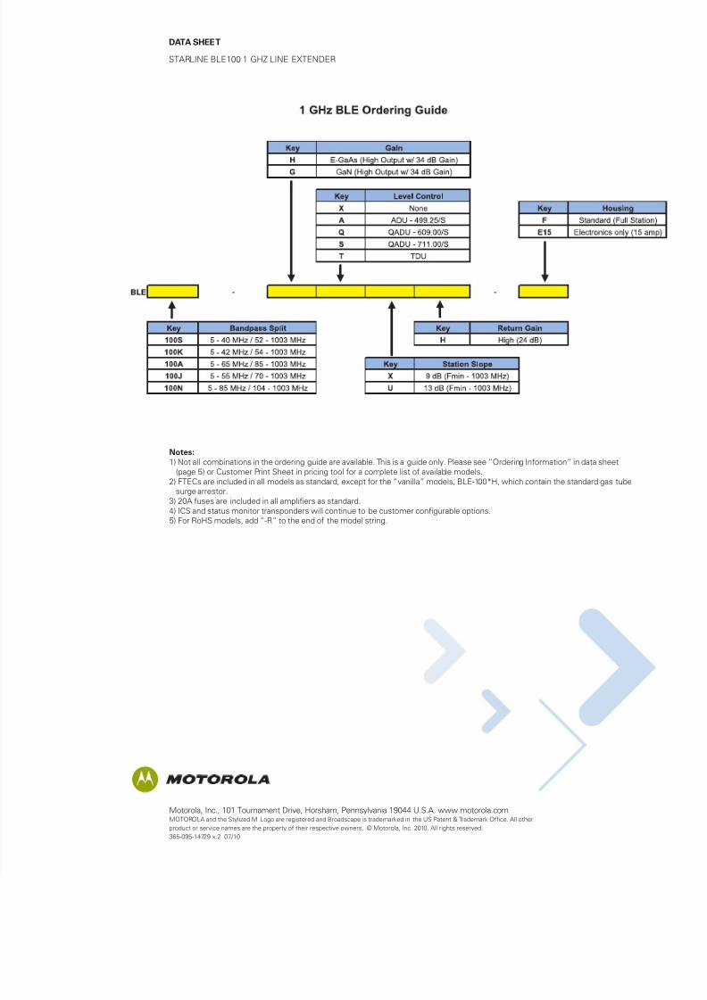
Notes:
1) Not all combinations in the ordering guide are available. This is a guide only. Please see “Ordering Information” in data sheet
(page 5) or Customer Print Sheet in pricing tool for a complete list of available models.
2) FTECs are included in all models as standard, except for the “vanilla” models, BLE-100*H, which contain the standard gas tube
surge arrestor.
3) 20A fuses are included in all amplifiers as standard.
4) ICS and status monitor transponders will continue to be customer configurable options.
5) For RoHS models, add “-R” to the end of the model string.