Blast Design and Vibration Control at Kayad Lead-Zinc ... · PDF fileBlast Design and...
27
Blast Design and Vibration Control at Kayad Lead-Zinc Underground Mine CSIR - Central Institute of Mining and Fuel Research, Dhanbad, India 826 015 Pradeep K Singh, Chief Scientist & Professor, Academy of Scientific & Innovative Research
Transcript of Blast Design and Vibration Control at Kayad Lead-Zinc ... · PDF fileBlast Design and...

Blast Design and Vibration Control at Kayad Lead-Zinc Underground Mine
CSIR - Central Institute of Mining and Fuel Research, Dhanbad, India 826 015
Pradeep K Singh, Chief Scientist &
Professor, Academy of Scientific & Innovative Research

Introduction Drilling and blasting continues to be an important method of rock
excavation and rock breaking. Ground vibrations from blasting have been a constant problem
for the mining and construction industries, the public living near the mining activities and the regulatory agencies responsible for setting safety and environmental standards.
The three factors of ground vibrations that determine the degree of
shaking are ground vibration amplitude (peak particle velocity; PPV), its duration and its frequency.
The mining industry needs realistic design levels and also practical techniques to safe guard the structures in their periphery.
Last but not the least, the mining operations should not be stopped only due to apprehension of the damage to the structures/buildings.
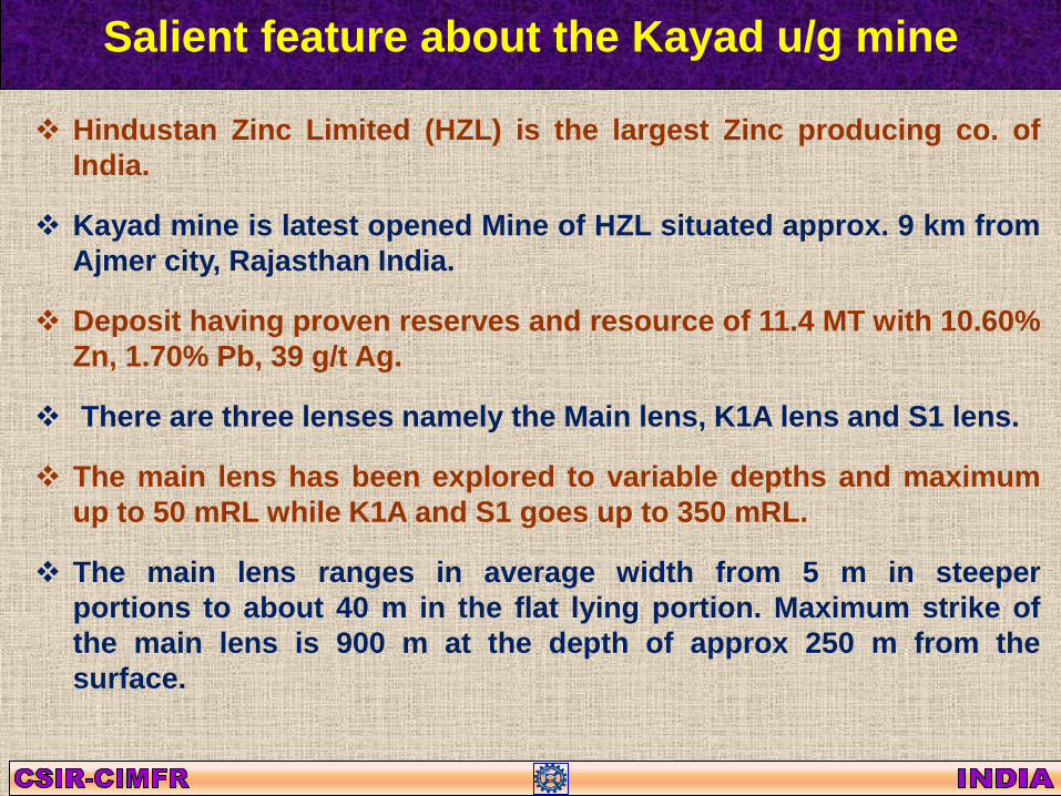
Hindustan Zinc Limited (HZL) is the largest Zinc producing co. of India.
Kayad mine is latest opened Mine of HZL situated approx. 9 km from Ajmer city, Rajasthan India.
Deposit having proven reserves and resource of 11.4 MT with 10.60%
Zn, 1.70% Pb, 39 g/t Ag. There are three lenses namely the Main lens, K1A lens and S1 lens. The main lens has been explored to variable depths and maximum
up to 50 mRL while K1A and S1 goes up to 350 mRL.
The main lens ranges in average width from 5 m in steeper portions to about 40 m in the flat lying portion. Maximum strike of the main lens is 900 m at the depth of approx 250 m from the surface.
Salient feature about the Kayad u/g mine
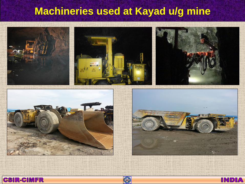
Machineries used at Kayad u/g mine

Blasting details In total 1203 blasts were performed and 2612 vibration data were
recorded on the surface in the periphery of the mine. Development face blast : 1041 Slot raise blast: 110 Ring blast : 52
Dia. of blast holes: 45 mm - development face blasting 76 mm - slot raise and ring blasts 102 mm – Reamers holes
No. of holes: 17 to 78 in case of development face blasting
No. of holes: 2 to 13 in case of Slot raise and ring blasting
Total explosives weight detonated in blast around : 70 to 310 kg
Explosives weight / delay : 3.90 to 18.75 kg
Initiation System : NONEL (shock tube) & Electronic delay detonators
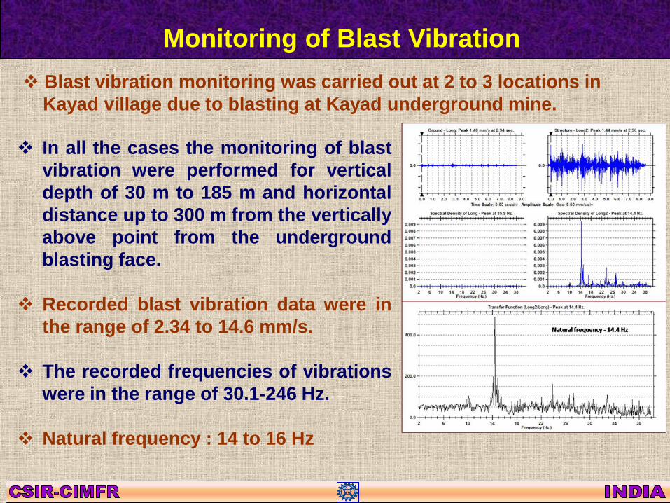
Blast vibration monitoring was carried out at 2 to 3 locations in Kayad village due to blasting at Kayad underground mine.
In all the cases the monitoring of blast vibration were performed for vertical depth of 30 m to 185 m and horizontal distance up to 300 m from the vertically above point from the underground blasting face.
Recorded blast vibration data were in the range of 2.34 to 14.6 mm/s.
The recorded frequencies of vibrations
were in the range of 30.1-246 Hz.
Natural frequency : 14 to 16 Hz
Monitoring of Blast Vibration

View of Vibration Monitoring Locations

Blast wave signature of development face blast

Development face blast propagation equation
Correlation co-efficient = 84.2 % v = Peak particle velocity (mm/s) R = Distance between vibration monitoring point and blasting face (m) Qmax = Maximum explosive weight/delay (kg)

Plot of dominant peak frequencies of vibration
The recorded frequencies of vibrations were in the range of 30.1-246 Hz. The Fast Fourier Transform (FFT) analyses of vibration data obtained shows that the concentrations of vibration energy were in the range of 50-150 Hz.
The safe level of vibration has been taken as 15 mm/s for the safety of houses/ structures as per DGMS standard.

Development face blasting
The Development blast face were conducted with different blast design in order to optimize blast design parameters and to control ground vibration at lowest possible levels.
Initially, the blast were conducted with delay intervals of 15ms, 20ms and 25ms between the holes for detonation of 5 center holes taking one by one and the recorded vibration signatures with high sampling rate were analyzed.
It was found that the delay interval of 25ms resulted into generation of lower level of ground vibration.
The delay interval between subsequent holes were provided with 50ms with a jump delay of 200ms and 100ms at two sectional cut.
The overall pull of the blast was in the range of 70-80%.
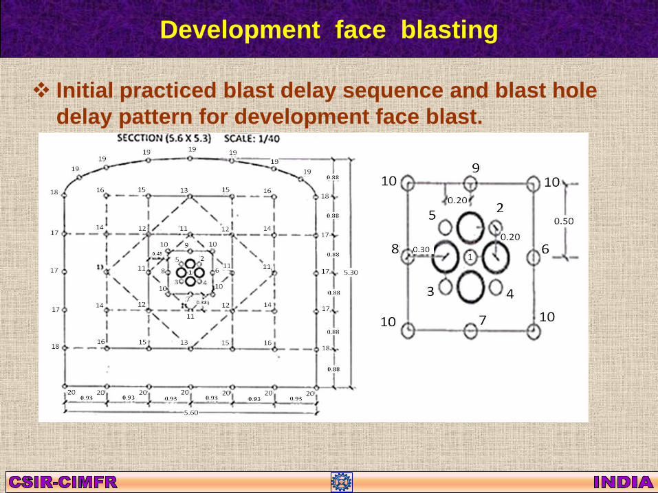
Initial practiced blast delay sequence and blast hole delay pattern for development face blast.
Development face blasting
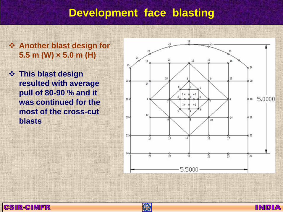
Another blast design for 5.5 m (W) × 5.0 m (H)
This blast design resulted with average pull of 80-90 % and it was continued for the most of the cross-cut blasts
Development face blasting

The design was slightly modified for decline and main faces blasts particularly in the drill design i.e., burden and spacing of the blast holes.
The average pulls obtained in this modified design were of 90-95 %.
Development face blasting

Hole no. Delay [ms] Delay interval [ms]
Hole no. Delay [ms] Delay interval [ms] Hole no. Delay [ms] Delay interval [ms]
1 0 22 1150 50 43 2200 50 2 25 25 23 1200 50 44 2250 50 3 50 25 24 1250 50 45 2300 50 4 75 25 25 1300 50 46 2350 50 5 100 25 26 1350 50 47 2400 50 6 300 200 27 1400 50 48 2450 50 7 350 50 28 1450 50 49 2500 50 8 400 50 29 1500 50 50 2550 50 9 450 50 30 1550 50 51 2600 50
10 550 100 31 1600 50 52 2650 50 11 600 50 32 1650 50 53 2700 50 12 650 50 33 1700 50 54 2800 100 13 700 50 34 1750 50 55 2850 50 14 750 50 35 1800 50 56 2900 50 15 800 50 36 1850 50 57 2950 50 16 850 50 37 1900 50 58 3000 50 17 900 50 38 1950 50 59 3050 50 18 950 50 39 2000 50 60 3100 50 19 1000 50 40 2050 50 61 3150 50 20 1050 50 41 2100 50 62 3200 50 21 1100 50 42 2150 50 63 3250 FACE (Width – 5.6 m and Height – 5.2 m)
Hole Type No. of holes
Cartridge per hole Explosives per hole Explosives quantity
Cut holes 17 11 11 × 0.395 g = 4.34 kg 73.8 kg (187 cartridges) Easers or reliever holes 30 10 10 × 0.395 g = 3.95 kg 118.5 kg (300 cartridges)
Lifter holes 7 11 11 × 0.395 g = 4.34 kg 30.4 kg (77 cartridges) Perimeter holes 9 8 8 × 0.395 g = 3.16 kg 28.4 kg (56 cartridges)
Total explosive used in (kg) 251 kg (620 cartridges)
Charging pattern of development face blasting

Slot raise blasting
The slot raise blasts commented after sufficient development blasts were performed in north and south decline faces. The numbers of holes and deck charging were modified to get desired pull from the slot raise blast.
The maximum pull of 2.7 m was recorded in a few blasts. The explosives loaded in slot holes were 4.5 to 9.4 kg . The number of blast holes varied between 3 and 14 depending
upon the condition of blast holes. The total explosives in a blast round varied between 16 and 172 kg.

Slot raise blasting

Ring blasting
Initially, the ring blasting started with emulsion cartridge explosives of 150 kg distributed in 5 blast holes and were detonated keeping the explosive weight per delay of 25 kg.
No. of blast holes in case of ring blasting : 2 to 7. Total explosives detonated in a blasting round: 64 to 340 kg
Explosives weight per delay : 11 to 17 kg In this case a few blast holes were decked up to 4 places with the
help of electronic delay detonators. On the basis of waveform analysis, the delay interval of 20ms to
80ms at an interval of 20ms is found optimal in case of deck charging while the minimum delay of 40ms to maximum of 80ms is to be provided between the two successive blast holes.

Ring blasting

Blast wave signature of ring face blast
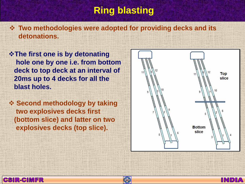
Two methodologies were adopted for providing decks and its detonations.
Ring blasting
The first one is by detonating hole one by one i.e. from bottom deck to top deck at an interval of 20ms up to 4 decks for all the blast holes.
Second methodology by taking two explosives decks first (bottom slice) and latter on two explosives decks (top slice).
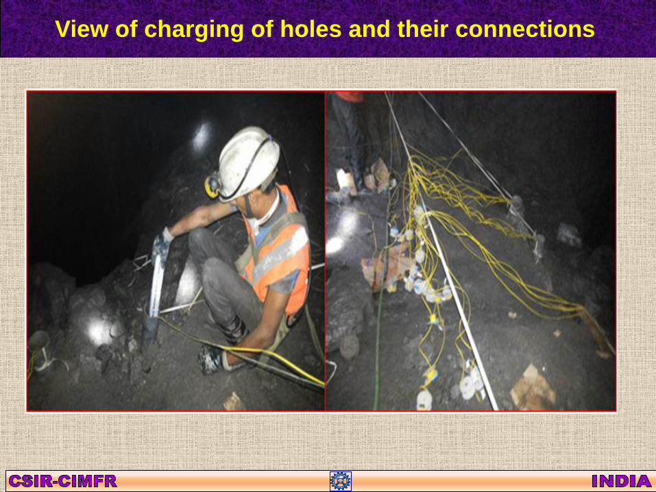
View of charging of holes and their connections

In-the-hole VOD measurement in ring blast holes The in-the-hole continuous velocity of detonation of emulsion
explosives was also recorded for 4 holes of Ring.
Out of 4 holes 3 holes were deck charged.
The recorded in-the- hole VOD of explosi- ves of 1st hole were in the range of 4846- 4890 m/s.

In-the-hole VOD measurement in ring blast holes
The recorded in-the-hole VOD of explosives of 2nd hole were in the range of 5224-5260 m/s.

Fragmentation analyses
The fragmentation results of ring blast of S-2 Stope (Ring 5): Average mean size of
the block is 0.643 m The most common size
of the block - 0.532 m. The maximum size of
the boulder is 1.2 m.
Conclusions
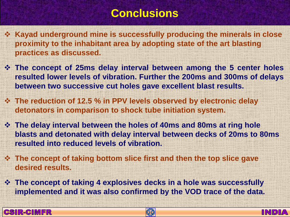
Kayad underground mine is successfully producing the minerals in close proximity to the inhabitant area by adopting state of the art blasting practices as discussed.
The concept of 25ms delay interval between among the 5 center holes resulted lower levels of vibration. Further the 200ms and 300ms of delays between two successive cut holes gave excellent blast results.
The reduction of 12.5 % in PPV levels observed by electronic delay detonators in comparison to shock tube initiation system.
The delay interval between the holes of 40ms and 80ms at ring hole blasts and detonated with delay interval between decks of 20ms to 80ms resulted into reduced levels of vibration.
The concept of taking bottom slice first and then the top slice gave desired results.
The concept of taking 4 explosives decks in a hole was successfully implemented and it was also confirmed by the VOD trace of the data.