
Blanking of Low-Carbon Steel
3
: . . .' " I 32 B.I.ANKING OF LOW·CARBON STEEL I i. ; i I " , : I" l '- l ' ; t'" .. s c r o P ' _ " ' ~ = = = - ~ s ~ b ) 4F O s ~ p ~ t ) Blonk For , med box Fig, 4, Notched work illu.stratlng use 01 notchinQ' fo r /reelnQ' 01 metal be/ore draw ln g (a ) an d be/ore formirtg (b), an ã lo r removing excess metal be/ore lormlng (c ) Fig. 5, Strip lanced to free metal fo r forming Piereing of ho!es of an y shape in a strip to fre e meta! for subsequent forming, or to produee surfaees that Iater coincide with th e outllne of a blanked part, is sometimes called semi notching. Th e pierced area ma y outllne a portion of on e part, or of two or more adjaeent parts in a strip. Progressive di e layouts Incorporatlng seminotchlng ar e lllustrated in Fig. 2, 18 a n d 31. Lancing is a press operation in whieh a slngle-line cu t or sllt is ma de part wny across the strlp stock, wlthout re ll10ving an y metal. Oenerally, lancing ls done to free metal for formlng, as shown In FIg. 5, or as in forming lou verso Th e eu t does no t have a closed contour a nd does n o t release a blank ar a plece of scrap. Besldes !ts use in freelng metaí fo r subsequent formlng, lanclng also is used to cut partia! con tours for blanked parts, partlcularly In progressive dies. Trimming is nn operation for remov in g excess metal (such as deformed a nd uneven metal on drawn or formed parts) and metal that has been needed In a previous opeI'ation (such as a blankholding flange for a draw opera tlon). Trlmmlng Is done In several ways, depending on th e shape of th e workp ie ce, on th e accuracy required, an d on production quantlty. Figure 6 lllustrates th e tooling fo r trimming a horizontal flange on a drawn shell in a s e p a r a t ~ operation. The drawn shell ls set on a locating plug for trlmmlng. After scrap from a sufficient number of trimmed shells ha s accumulated, th e piece of scrap a t th e bottom Is severed a t eaeh stroke of th e press b y th e scrap cutters shown in Fig. 6, an d falls e l ear. Except that th e dle must be construeted to aecept an d 10 cate th e drawn shell , th e operation ls ldentical with th e blanklng o f a flat workpiece a nd produces square edges of th e same aecuracy an d qual1ty. A drawn shell or formed part may be trlmmed in a press wlthout leavlng a flange on the completed part, by on e of three methods: plnch trlm, shlmmy trlm, or trlm a nd wlpe-down. Plnch trlmmlng, shown as a separate oper atlbn In a push-through dle In Flg. 7, la done only on a part that ha a a t least a narrow flange aS-formed , Th e shell must be free Crom wrlnkles a t or near th e trlmmlng . IIne. Th e trlmmed edge Is Ilot square wlth tl1e slde wall, but has th e general shape showll In th e lower rlght corl1er of lg. 7. A c c u ~ a c y of helght re s ultIng from plnch trlmmlng la afIeeted by varlatlon In waU thlekness an d fiange nidlus. To be Bure of an even plneh-otf alld to avold shllrp or rough edgelJ, clearance between punch an d dia must be held to a mlnlmum, an d th e pune h must be kept sharp, Plnch trlmmll1g la a L ~ o done wlthout a blo.nkholder OI' hold-down, uslng adie other wlse slmllo.r to that shown In Flg. 7. Th e scrap rlngs may be blown oH th e dl e at each stroke. In another method, the scrap rlngs cllmb th e punch untll they ar e severed by belng compressed agalnst a scrBp cutter, after whlch they ar e spread apart an d allowed to run out along a trnck for dlsposal. Plnch trlmmlng wlthout a blankholder Is partlcular 1y well sulted for us e In 1Ilgh-volume produc tlonJI eyelets an d other small partB, FIg. 6, Single-operatton dte lo r trtmmtng a horizontal flange OU' a drawu shell Trimming punch Blonkholder Workpiece ~ } } T r l m m e d "'- edge ••• Workpiece Oie Oeloll A (before workplece Is Irlmmed) Flg. 7. Plnch trlmming a drawn ~ h e l l in a push-through dle . , . ,, . . Plnch trlmmlng Is prlmurlly e. mass ductlon melhod, Th e productlon rate 15 beca use only one stroke of th e press Qulred to complete lh e lrlm, Th e m often Is comblned wlth drawing In a pound draw-and-trlm dle, to reduce pr t10n cost sllll further. Dlsadvantages ar e excesslve burrs, cu t edge, an d hlgh dle malntenanee. Shimmy Trlmmlng. In trlmmlng w 8hlmmy dl e (known al50 as Brehm or trlmmlng), the drawn shell Is held close-flttlng dl e of the exact shell helgh l 18 trlmmcd In I;egmcnts by successlve zontal osclllatlon" or a n InternaI cam-ael punch toward th e outside o( th e shell resultlng trlmmed edge Is sQuare an d ( resembles th e convenllonal blanked ed l o. f1at parto 8hell helght 18 more M< than wlth plnch trlmmlng. Besldeli ltB appllcatlon to shells that have square, accurate edges, shlmmy t r ln 18 used 011 shellll that have a wrlnkl otherwlse nonunHorm top edge as-drawn oH Is done below the detecta), an d on that cannot be produced economlcally even the narrow flange need e d for trlmmlng, Toollng cost fo r shlmmy trlmmlng 15 hlgher than fo r plnch trlmmlng. Also, sh trlmmlng Is slower, because 1t requlrel or more osclllatlons of th e punch In one stroke an d cannot be combined with operatlons In a c o n ~ ; J o u n d dle. Shlmmy dles ar e Inexpensive to ma l because they remaln In allgnment and are not IIkely to wear by shearlng or chl l Trim anel Wlpe·Down. In thls type oí rulng, a f1ange Is cu t to wldth wlth Buch as that shown In Flg, 6. anrl thcn o r stralghtened Into IIne wlth th e \ 1 i th e shell 01 ' fonned part. Because of n f1ange wldth, trimmlng an d wlplng dOWI be two operatlons, Th e edge Is square wlth th e sldewaJ the shell he l g h t rnay be sllghtly 1m , because of th e form!ng characterlstlcs ( metal. Al so , a. rlng ma y be vlslble a original locatloll of Lhe flangc radlus, Trimming, oLheI' than shímmy 1 ming, Is frequently combined with or more other operatíons in a I pound dle. Trim stoek often Is left drawn or formed workpiece so th ca n be trlmmed to size in a seeon c eration. Thls is dane to ge t the . accurate relation of s ome otheI' fea Buch as a plerced hole, to th e trlrr . outl1ne of the workpiece. Characteristics of Blanked Ed ! The sheared edges of a blank d u e ~ d in a convention a l die are smooth a nd vertical for th e el th!ckness of th e part, bu t insteM ! th e charaeteristlcs represented ot exaggerated seale in F ig . 8. The li ls shown in th e position in whic would be cu t from th e work me ta th e downward motion of th e pu n e. portion of th e stock rcmaining aft e: moval of th e bJank 13 shown at th! of th e lllustratlon. Rollover on th e lowcr edgcs 01 blank develops by plastlc deforrm of th e work metal as it is forceo th e die by th e punch. Co m pressiQ th e metal above th e rollover against th e wa l '8 of tlle die op.: burnishes a portlOJ , qf th e edge o: bIank, as shown in Fig. 8, As the Il' completes its stroke, th e re m a: portlon of th e blank edge 13 br · away or fraetured (re s ulting In . break"), a n d a tensile burr is f l.; along th e to p of th e blanJc edgc. i Tl1e angle of the fractur ed p o r t th e edge ls ldentifteà In Fig. 8 a; breakout angIe. Th e breakout dl slon of th e blank and the burnlz menslon of th e bole in the ,
-
Upload
ricardo-pace -
Category
Documents
-
view
227 -
download
0
Transcript of Blanking of Low-Carbon Steel
8/2/2019 Blanking of Low-Carbon Steel
http://slidepdf.com/reader/full/blanking-of-low-carbon-steel 1/2
: . .
.'"I
32 B.I.ANKING OF LOW·CARBON STEEL
I i.;iI
",:I"
l '-
l' ; t'"..
s c r o P ' _ " ' ~ = = = -~ s ~ b) 4F
O s ~ p ~ t ) Blonk For,med box
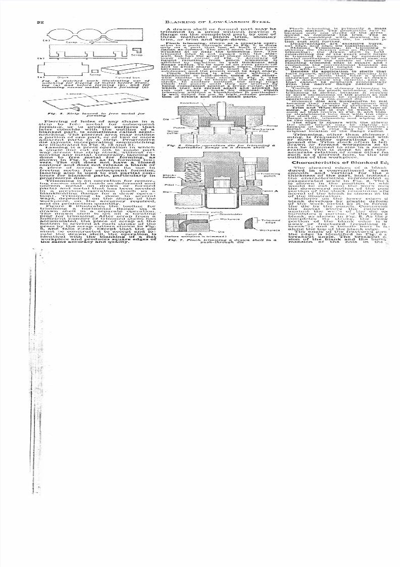
Fig, 4, Notched work illu.stratlng use 01
notchinQ' fo r /reelnQ' 01 metal be/ore drawln g (a ) and be/ore formirtg (b) , anã lo rremoving excess metal be/ore lormlng (c )
Fig. 5, Strip lanced to free metal fo rforming
Piereing of ho!es of an y shape in astrip to free meta! for subsequentforming, or to produee surfaees thatIater coincide with th e outllne of ablanked part, is sometimes called seminotching. The pierced area ma y outllnea portion of one part, or of two or moreadjaeent parts in a strip. Progressivedie layouts Incorporatlng seminotchlngare lllustrated in Fig. 2, 18 and 31.
Lancing is a press operation in whieha slngle-line cu t or sllt is made partwny across the strlp stock, wlthout re ll10ving any metal. Oenerally, lancing lsdone to free metal for formlng, asshown In FIg. 5, or as in forming louverso The eu t does no t have a closedcontour and does not release a blank ara plece of scrap. Besldes !ts use infreelng metaí for subsequent formlng,lanclng also is used to cut partia! contours for blanked parts, partlcularly Inprogressive dies.
Trimming is nn operation for removin g excess metal (such as deformed anduneven metal on drawn or formedparts) an d metal that ha s been neededIn a previous opeI'ation (such as ablankholding flange for a draw operatlon). Trlmmlng Is done In severalways, depending on th e shape of th eworkpiece, on the accuracy required,an d on production quantlty.
Figure 6 lllustrates th e tooling fortrimming a horizontal flange on adrawn shell in a s e p a r a t ~ operation.The drawn shell ls set on a locatingplug for trlmmlng. After scrap from asufficient number of trimmed shells ha saccumulated, th e piece of scrap at th ebottom Is severed at eaeh stroke of th e
press by the scrap cutters shown in Fig.6, an d falls e lear. Except that th e dlemust be construeted to aecept an d 10cate th e drawn shell, th e operation lsldentical with th e blanklng of a flatworkpiece and produces square edges ofthe same aecuracy an d qual1ty.
A drawn shell or formed part may betrlmmed in a press wlthout leavlng aflange on the completed part, by one ofthree methods: plnch trlm, shlmmytrlm, or trlm and wlpe-down.
Plnch trlmmlng, shown as a separate oper
atlbn In a push-through dle In Flg. 7, la doneonly on a part that ha a at least a narrowflange aS-formed , Th e shell must be free Cromwrlnkles at or near th e trlmmlng . IIne. Th etrlmmed edge Is Ilot square wlth tl1e sldewall, but has th e general shape showll In th elower rlght corl1er of Flg. 7. A c c u ~ a c y ofhelght resultIng from plnch trlmmlng laafIeeted by varlatlon In waU thlekness an dfiange nidlus. To be Bure of an even plneh-otfalld to avold shllrp or rough edgelJ, clearancebetween punch an d dia must be held to amlnlmum, an d th e puneh must be kept sharp,
Plnch trlmmll1g la a L ~ o done wlthout ablo.nkholder OI' hold-down, uslng ad ie otherwlse slmllo.r to that shown In Flg. 7. Th escrap rlngs may be blown oH th e dle at eachstroke. In another method, the scrap rlngscllmb th e punch untll they are severed bybelng compressed agalnst a scrBp cutter, afterwhlch they are spread apart an d allowed to
run out along a trnck for dlsposal. Plnchtrlmmlng wlthout a blankholder Is partlcular1y well sulted for use In 1Ilgh-volume productlonJI eyelets an d other small partB,
FIg. 6, Single-operatton dte lo r tr tmmtng ahorizontal flange OU' a drawu shell
Trimming punch
Blonkholder
Workpiece ~ } } T r l m m e d "'- edge
••• Workpiece
Oie
Oeloll A(before workplece Is Irlmmed)
Flg. 7. Plnch trlmming a drawn ~ h e l l in apush-through dle
. ,. ,, . .
Plnch trlmmlng Is prlmurlly e. massductlon melhod, Th e productlon rate 15because only one stroke of th e pressQulred to complete lh e lrlm, Th e moften Is comblned wlth drawing In apound draw-and-trlm dle, to reduce prt10n cost sllll further.
Dlsadvantages ar e excesslve burrs,
cu t edge, an d hlgh dle malntenanee.Shimmy Trlmmlng. In trlmmlng w
8hlmmy dle (known al50 as Brehm ortrlmmlng), the drawn shell Is heldclose-flttlng dle of the exact shell helghl18 trlmmcd In I;egmcnts by successlvezontal osclllatlon" or an InternaI cam-aelpunch toward th e outside o( th e shellresultlng trlmmed edge Is sQuare and (resembles th e convenllonal blanked ed lo. f1at parto 8hell helght 18 more M<than wlth plnch trlmmlng.
Besldeli ltB appllcatlon to shells thathave square, accurate edges, shlmmy tr ln 18 used 011 shellll that have a wrlnkl otherwlse nonunHorm top edge as-drawn oH Is done below the detecta), an d on that cannot be produced economlcally even the narrow flange needed for trlmmlng,
Toollng cost for shlmmy trlmmlng 15
hlgher than for plnch trlmmlng. Also, shtrlmmlng Is slower, because 1t requlrelor more osclllatlons of th e punch In onestroke an d cannot be combined withoperatlons In a c o n ~ ; J o u n d dle.
Shlmmy dles are Inexpensive to malbecause they remaln In allgnment andare not IIkely to wear by shearlng or chll
Trim anel Wlpe·Down. In thls type oírulng, a f1ange Is cu t to wldth wlthBuch as that shown In Flg, 6. anrl thcnor stralghtened Into IIne wlth th e t \ 1 i th e shell 01 ' fonned part. Because of nf1ange wldth, trimmlng an d wlplng dOWIbe two operatlons,
Th e edge Is square wlth th e sldewaJthe shell he lght rnay be sllghtly 1m,because of th e form!ng characterlstlcs (metal. Also, a. rlng ma y be vlslble aoriginal locatloll of Lhe flangc radlus,
Trimming, oLheI' than shímmy 1ming, Is frequently combined withor more other operatíons in a I
pound dle. Trim stoek often Is leftdrawn or formed workpiece so thca n be trlmmed to size in a seeonceration. Thls is dane to get the .accurate relation of some otheI' feaBuch as a plerced hole, to th e trlrr.outl1ne of the workpiece.
Characteristics of Blanked Ed !
The sheared edges of a blankd u e ~ d in a conventional die aresmooth and vertical for th e el
th!ckness of the part, but insteM !th e charaeteristlcs represented ot
exaggerated seale in Fig. 8. The lils shown in th e position in whicwould be cu t from the work me tath e downward motion of th e pune.
portion of th e stock rcmaining afte:moval of th e bJank 13 shown at th!of th e lllustratlon.
Rollover on th e lowcr edgcs 01
blank develops by plastlc deforrmof the work metal as it is forceothe die by th e punch. CompressiQthe metal above the rolloveragainst th e wa l'8 of tlle die op.:burnishes a portlOJ , qf th e edge o:bIank, as shown in Fig. 8, As the Il'
completes its stroke, th e rem a:
portlon of th e blank edge 13 br ·away or fraetured (re sulting In .
break") , and a tensile burr is f l.;along the to p of th e blanJc edgc. i
Tl1e angle of the fractured p o r tth e edge ls ldentifteà In Fig. 8 a;
breakout angIe. Th e breakout dlslon of th e blank and the burnlzmenslon of th e bole in the ,
8/2/2019 Blanking of Low-Carbon Steel
http://slidepdf.com/reader/full/blanking-of-low-carbon-steel 2/2
33
~ s i z e .
,,{
°o
.• . t n g'\ h~ ; .
>
.;.:;
ge
o
lide are
U
y
-.lo
" l th
:t i l . Also,
es
a n c e .
ee ton are approximateIy equal to th e. sponding puneh dimension, andburnlsh dimenslon of the blank lsdose to the eorresponding die dion. Thus, the punch determines
hoie slze and the dle governs th e
:" Ptnetration depth, or the amount oft.etratlon of the puneh Into th e work
1before fracture oecurs, ls shownhe edge of the remalning stoek or
p skeleton In Fig. 8. Thls depth isxlmately equal to the Bum of rolldepth and burnlsh depth on the
k, except when low dle elearance\Jeea secondary burnlsh. I t 13 usual
expressed as a percentage of th eo: .c.<'I'1rk·metal thlckness. o
) The percentage of penetration (belme fracture) depends on the proper
rif t h ~ work metal, as shown In Tal, which gives approximate values
or rarlous steels and nonferrous metll s under typical blanklng eondlt1ons.
<Jmentage penetration atIects energy; I»nsumptlon and cuttlng force In blank
ns descrlbed under "Calculation oflte Requirements", on thls page.
Die Clearance
T h e terms c1earance, dle clcarance,';'alld punch-to-dle clearance are used': ,l'1nonymously to refer to th e space be
: , . , l f f i ! n punch and die. Clearance is Imtant for reliable operation of th enklng equipment, quality an d typeeut edges. and !ife of punch and die.~ ~ n e r a l , the effects of clearance on
:t these factors in blanking are the same00A/l In plercíng, and are discussed on
14 in the ar t iele "Plerelng ofCarbon Steel".
The edge eharacterlstics of slugs proIn plercing holes are described
pages 44 and 45 in th e article onrcing. and are illustrated in Fig. 2
of lhat article. The data in that lllusitQtlon can serve as a guide for selectl'ng clearances for blanking. . ~ U clearance values glven In thls ar
per slde, except where lndlti otherwlse.
Optimum blanking clearance mayJCr.letlmes be less than optlmum pleremg clearance. This Is partly because'!.he blanked edge generally 1s elose to
stock edge, and material expansíonm etore Is less restricted. A pierclng
\"001must move a great deal of materialfrorn !ts cuttlng edge and, for
gest lHe, the clearance should be se .ted to elirnlnate as much compresslve
Joadtng on the work metal as possible.Apart blanked uslng c1earance much
tlTeater than normal may show doubleü ,u r. whlch ordinarlly is evldent only
extremely small cIearanee (seefttge types 4 and 5 in Fig. 2 on page
a part blanked uslng largedrarance \viU be smaller than the dieOlltning (except for a deeply dishedbll:lk), and it is d!fficult to correct th e
llng to compensate for this. In someppllcations, retalnlng the blank be
almost as great a problem asng the slugs Into a dle cavity
,atter pierclng, because of the increasedo
&elíd in a blanlclng die (Fig. 9) 18 ttle taper that 18 provlded 80 that the ;MTered blank can fall free. The relief
'bgle may range from y'\0 to 2· ' from
BLANKING OF LOW-CARUON STEEL
__ Appro,imalelydie diomeler
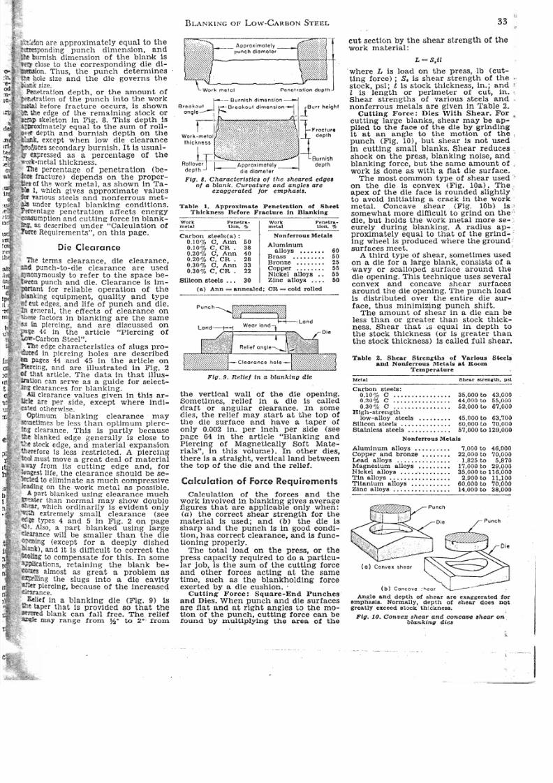
Ftg. 8. Charactertsttcs 01 the sheared edgel01 a blank o Curvature and angles are
exaggerated jo r empha8t8.
Table 1. Approxlmate Penetratlon oi Sheei T h l c k n ~ s 9 Ucfore Fracture In Blanklng
Work Penetra- Work Penetra ..
metal tlon. % _m.....t_a_'_ _ _ _loon, %
Carbon steels(a): Nonterrous MetaIs
0.10% C, Ann 50 AIumlnum
0010% C, CR . 38 alloys ••••••• 600.20% C, Ann 40
Brass ••••••••• 600020% C, CR . 20 Bronze , . . . . . . . 0250030% C, An n 33
Copper . . • • • • . • 550.30% C, CR . 22
Nlckel alloys .. 55 Slllcon steels . . . 30 Zlnc a11oY8 •••• 50
(a ) An n annealed; CR = cold rolled
p u n C h ~ 1-+-"0 LondL o n d _ ~ ~ ~ w ~ e ~ a ~ r l ~ o n ~ d ~ =
Flg o 9, Reltej In a blanking dte
th e vertical wall of th e die opening.Sometlmes, relle! in li. die is calleddraft or angular clearance. In somedles, th e rellef may start at the top ofth e d1e surface an d have a tape r ofonly 0.002 In. pe r Inch per side (see
page 64 In the artlcle "Blanking andPierclng of Magnetically Soft MateriaIs", in thls volume>. In other dies,there Is a stralght, vertlcalland betweenthe top of th e die and the relief.
Calculation of Force Requirements
Calculation of the forces and thework involved in blanklng gives averagefigures thatare applicable only when:(a ) th e correct shear strength for th ematerial i8 u8ed; an d (b ) th e die issharp and the punch i8 in good conditlon, ha s correct clearance, an d 1s runetionlng properly. o
The total load on the préss, or thepress capacity required to do a particula r job, 18 th e sum of the cutting forceand other forces acting at the sametime, such as the blankholding forceexerted by adie cushion. .
Cutting Force: Square-End Punches o
an d Dies. When punch an d dle surfacesare ftat an d at rlght angles to th e mo Uon of the punch, cuttlng force can be
found by multlply1ng the are a of the
cu t 8ectlon by th e shear strength of thework material:
L = S.tl
°where L is load on the pre8s,lb (cuttlng force); S. Is shear strength of th e "stock, psl; t is stock thickness, In.; a ~ d l Is length or perlmeter of cut, m. ,Shear strengths of various steels and .nonferrous metais are given in Table 2.
Cutting Force: Dies With Shear. For •
cutting lal'ge blanks, shear may be ap pl1ed to the face of th e die by grlndlnglt at an angle to th e motlon of the I
punch (Flg. 10), but shear 18 no t used In cuttlng small blanks. Shear reduces o;shock on th e press, blanking noise, andblanking force, bu t the same amount of <
work Is done as with a fiat die surface.The most common type of shear used "
on the die is convex (Fig. 10a). The ;apex of the dle face i5 rounded slightlyto avold init1atlng a craek in the workmetal. Cone ave shear (Figo 10b) is '!
somewhat more dlfficult to grlnd on th e "die, bu t holds the work metal more se - :curely during blanking. A radlus ap-.proximately equal to that of the grind- ;ing wheel Is produced where the ground :
surfaces meet.A third type of shear, sometlmes used
o
on a dle for a large blank, consists of awavy ar scalloped surface around th edle opening. This technique uses severalconvex an d concave shear surfacesaround the dle opening. The puneh loadis distributed over the entire die surface, thus minim!zing punch shift.
The amount of shear in adie can beless than or greater than stock thickness. Shear that equal in depth tothe stock thickness (or is greater thanthe stock thicknes8) 1s called fuH shear.
Table 2. Shear Strengths of Varlous Steela and NonIerrollS Metais a i Room
Tempt'rllture
Metal 8hear' . . . . .nith. ps l
Carbon ateeIs;0.10% C • . • • • . . • • • • . • . • • 35.000 to 43,0000020% C . . • • . • • • • • . • . . . . 44,000 to 55,0000030% C ................ 52.000 to 67.000
Hlgh-strengthlow-alloy ateeIs ,........ 45,000 to 63,700
Sll1con steeIs . • . • • . . • • • . • . • 60,000 to 70.000Stalnless steels • • • • . . . . . . . • 57,000 to 129,000
Nonferrous MetaIs
AIumlnum a110ys •••••••••• 7,000 to 46.000Copper and bronze •••••••• 22.000 to 70,000Lead alloys . o 1,825 to 5,870•••••••••••• o
Magneslum aJloys . • • • . . . • • 17,000 to 29,000Nlckel alloys • . . . • • • • • • . . • • 35.000 to 116,000T1n alloys . . . • • • • • • • • • • . . . • 2,900 to 11.100Titan!um alloys ••••••••••• 60.000 to 70,000Zlnc alloys . . • . . • • . . . . • . • • . 14,000 to 38,000
Punch
(b ) Concave ,oear
Pune h
Angle and depth of shear are exaggerated foremphasls. Normally, depth or I.Ihear does no igreatly exceed ato_clt thlckneB8. o
Fig. 10. Convex shear an d concave,hear onblankínl1 die,
1 . 0


