Bladder Accumulators - Airline Hydraulics
16
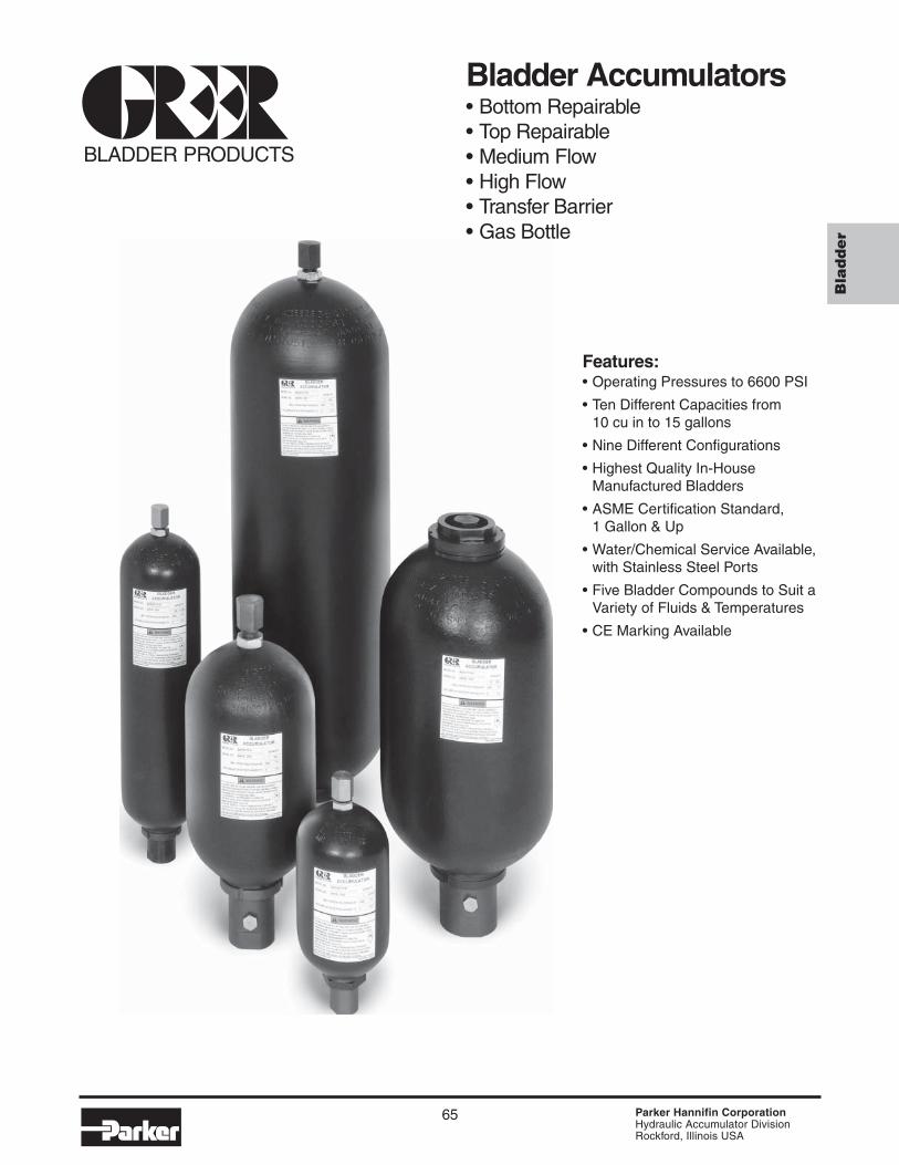
65 Parker Hannifin Corporation Hydraulic Accumulator Division Rockford, Illinois USA Bladder Bladder Accumulators • Bottom Repairable • Top Repairable • Medium Flow • High Flow • Transfer Barrier • Gas Bottle Features: • Operating Pressures to 6600 PSI • Ten Different Capacities from 10 cu in to 15 gallons • Nine Different Configurations • Highest Quality In-House Manufactured Bladders • ASME Certification Standard, 1 Gallon & Up • Water/Chemical Service Available, with Stainless Steel Ports • Five Bladder Compounds to Suit a Variety of Fluids & Temperatures • CE Marking Available BLADDER PRODUCTS
Transcript of Bladder Accumulators - Airline Hydraulics
65 Parker Hannifin CorporationHydraulic Accumulator DivisionRockford, Illinois USA
Bla
dder
Bladder Accumulators• Bottom Repairable• Top Repairable• Medium Flow• High Flow• Transfer Barrier• Gas Bottle
Features:• Operating Pressures to 6600 PSI
• Ten Different Capacities from10 cu in to 15 gallons
• Nine Different Configurations
• Highest Quality In-HouseManufactured Bladders
• ASME Certification Standard,1 Gallon & Up
• Water/Chemical Service Available,with Stainless Steel Ports
• Five Bladder Compounds to Suit aVariety of Fluids & Temperatures
• CE Marking Available
BLADDER PRODUCTS
Catalog HY10-1630/US Bladder AccumulatorsIntroduction
66 Parker Hannifin CorporationHydraulic Accumulator DivisionRockford, Illinois USA
Bladder accumulators provide a means of regulating theperformance of a hydraulic system. They are suitable forstoring energy under pressure, absorbing hydraulic shocks,and dampening pump pulsation and flow fluctuations. Bladderaccumulators provide excellent gas and fluid separationensuring dependable performance, maximum efficiency, andlong service life.
Why Use Bladder Accumulators?• improves system efficiency• supplements pump flow• supplies power in emergency
• compensates for leakage• absorbs hydraulic shocks• highly contaminant tolerant
• universal application• high/low temperature tolerance• safety, cannot be disassembled under pressure
• very quick response• works well with water, low lubricity fluids• wide range of compounds for a variety of fluids
Bladder Products…The Original and still the Best!The Greer bladder style accumulator is the industry's original,and still the best! For years this style of accumulator hasserved both the industrial and mobile hydraulic markets,providing a proven design for many hydraulic systemapplications.
The Greer bladder product line offers the broadest line ofquality products, including:
• 3000 & 5000 PSI Bottom Repairable• 3000 & 5000 PSI Top Repairable• 3000 PSI Medium Flow• 3000 PSI High Flow• 3000 PSI Transfer Barrier• 3000 & 5000 PSI Gas Bottles• A Wide Array of Options and Accessories
Greer bladder products maintain the highest quality becauseof our in-house bladder molding operations. The heart of thebladder accumulator is the actual bladder, and all Greerbladders are engineered and manufactured in our own facilityand subjected to our own high quality inspection standards.For your convenience, the latest in accumulator sizingtechnology is available with the inPHorm Accumulator Sizingand Selection Software.
SpecificationsMaterials• Shell – high strength alloy steel (SA372, all sizes comply
with ASME material specifications, 1 gal. & larger suppliedwith ASME Certification as standard)
• Ports – all oil service ports, high strength alloy steel– water & chemical service:
3000 psi, 304 stainless steel5000 psi, 17-4 PH stainless steel
• Poppet & Spring – 304 stainless steel• Gas Valve Cartridge – steel• Gas Valve Protector – steel• Gas Valve Stem – steel• Bladders – various polymers, see Standard and Optional
Bladders.
Maximum Flow Rates
Pressure Ratings – 3000 and 5000 psi bladder accumulatorsare rated at minimum 4 to 1 design factors as standard. 4000and 6600 psi (ASME Appendix 22) bladder accumulators areavailable as an option at minimum 3 to 1 design factors. Forpressures over 6600 psi, consult the factory.
Max. Recommended Compression Ratio (max. workingpressure/precharge pressure): 4 to 1.
Max. Recommended Flow Size for Standard Mineral Oils
(gallon) GPM LPM10 cu in 23 87
1 pt & 1 qt 40 151150 cu in 60 227
1 150 5682½ thru 15 220 833
2½ thru 15, Medium Flow 480 18192½ thru 15, High Flow 600 2271
Fluids – Greer bladder accumulators are compatible with awide variety of fluids. The standard accumulator may be usedwith petroleum-based industrial or water-based flame resistantfluids. Bladders compatible with most industrial fluids can befurnished on special orders with temperature ranges from-40°F to 250°F (-40°C to 121°C).
Precharge – Units are shipped with a nominal nitrogenprecharge as standard. For specific precharge pressures,specify at the time of order.
Available Options – a wide variety of options are available onGreer bladder accumulators including:• Bladder Compounds (see Standard and Optional
Bladders in this section).• Ports (see Options in this section)• Port Adapters (see Accumulator Accessories)• Water & Chemical Service (see Options in this section)• Gas Valves (see Options in this section)• Fuse Plugs Assemblies (see Options in this section)• Fixed Gauge Adapters (see Accumulator Accessories)
IntroductionSpecifications
Certifications – ASME Certification (Section VIII-Div. 1) isavailable as standard on bladder accumulators (1 gallon & up)and ASME Appendix 22 Certification as an option. See page 3for a complete certification summary.
Std. ASME Cert. ASME Appendix 22
Size Status Rating D.F.* Rating D.F.*10 thru 150 in3 Consult
3000 PSI Option 3000 PSI 4 to 1 Factory1 thru 15 gal.
3000 PSI Std. 3000 PSI 4 to 1 4000 PSI 3 to 11 thru 15 gal.
5000 PSI Std. 5000 PSI 4 to 1 6600 PSI 3 to 1
*Note: D.F. = Design Factor.
Catalog HY10-1630/UStontent Bladder AccumulatorsIntroduction
67 Parker Hannifin CorporationHydraulic Accumulator DivisionRockford, Illinois USA
7
3
7
1
2
5
4
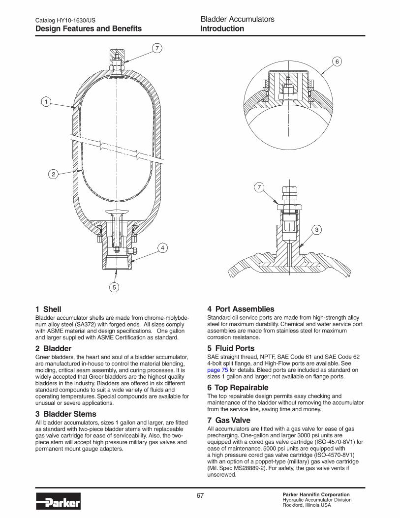
1 ShellBladder accumulator shells are made from chrome-molybde-num alloy steel (SA372) with forged ends. All sizes complywith ASME material and design specifications. One gallonand larger supplied with ASME Certification as standard.
2 BladderGreer bladders, the heart and soul of a bladder accumulator,are manufactured in-house to control the material blending,molding, critical seam assembly, and curing processes. It iswidely accepted that Greer bladders are the highest qualitybladders in the industry. Bladders are offered in six differentstandard compounds to suit a wide variety of fluids andoperating temperatures. Special compounds are available forunusual or severe applications.
3 Bladder StemsAll bladder accumulators, sizes 1 gallon and larger, are fittedas standard with two-piece bladder stems with replaceablegas valve cartridge for ease of serviceability. Also, the two-piece stem will accept high pressure military gas valves andpermanent mount gauge adapters.
4 Port AssembliesStandard oil service ports are made from high-strength alloysteel for maximum durability. Chemical and water service portassemblies are made from stainless steel for maximumcorrosion resistance.
5 Fluid PortsSAE straight thread, NPTF, SAE Code 61 and SAE Code 624-bolt split flange, and High-Flow ports are available. Seepage 75 for details. Bleed ports are included as standard onsizes 1 gallon and larger; not available on flange ports.
6 Top RepairableThe top repairable design permits easy checking andmaintenance of the bladder without removing the accumulatorfrom the service line, saving time and money.
7 Gas ValveAll accumulators are fitted with a gas valve for ease of gasprecharging. One-gallon and larger 3000 psi units areequipped with a cored gas valve cartridge (ISO-4570-8V1) forease of maintenance. 5000 psi units are equipped witha high pressure cored gas valve cartridge (ISO-4570-8V1)with an option of a poppet-type (military) gas valve cartridge(Mil. Spec MS28889-2). For safety, the gas valve vents ifunscrewed.
6
IntroductionDesign Features and Benefits

Catalog HY10-1630/US Bladder AccumulatorsIntroduction
68 Parker Hannifin CorporationHydraulic Accumulator DivisionRockford, Illinois USA
Models Dimensions, inch (mm) Hydraulic Ports WeightOil Service Gallon cu in H I lbs.Water Service (Liters) (Liters) A B C D E F G (Thread) (Thread) (Kg.)BAC10B3T01A1 10 cu in 12 11.18 1.56 2.25 1.03 0.94 7.75 0.94 SAE#8 N/A 3.5BAC10B3T01WA1 (0.16) (0.21) (284) (40) (57) (26) (24) (197) (24) (3/4 - 16) (1.6)
BA001B3T01A1 1 Pt. 31 10.75 2.00 3.40 1.39 1.31 6.87 0.94 SAE #12 N/A 8BA001B3T01WA1 (0.47) (0.51) (273) (51) (86) (35) (33) (174) (24) (1-1/16 - 12) (3.6)
BA002B3T01A1 1 Qt. 66 11.12 2.00 4.50 1.62 1.50 7.63 0.94 SAE #12 N/A 10BA002B3T01WA1 (0.95) (1.08) (282) (51) (114) (41) (38) (194) (24) (1-1/16 - 12) (4.5)
BA005B3T01A1 150 cu in 156 19.56 2.08 4.50 1.62 1.50 15.50 0.94 SAE #16 N/A 20BA005B3T01WA1 (2.5) (2.56) (497) (53) (114) (41) (38) (394) (24) (1-5/16 - 12) (9.1)
BA01B3T01A1 1 231 17.00 3.50 6.75 2.37 2.13 11.36 1.25 SAE #20 SAE #6 34BA01B3T01WA1 (3.79) (3.79) (432) (89) (171) (60) (54) (289) (32) (1-5/8 - 12) (9/16 - 18) (15)
BA02B3T01A1 2.5 556 21.38 3.62 9.06 3.00 2.88 15.50 1.25 SAE #24 SAE #6 80BA02B3T01WA1 (9.46) (9.11) (543) (92) (230) (76) (73) (394) (32) (1-7/8 - 12) (9/16 - 18) (36)
BA05B3T01A1 5 1124 33.38 3.62 9.06 3.00 2.88 27.50 1.25 SAE #24 SAE #6 120BA05B3T01WA1 (18.9) (18.42) (848) (92) (230) (76) (73) (700) (32) (1-7/8 - 12) (9/16 - 18) (55)
BA10B3T01A1 10 2097 54.38 3.62 9.06 3.00 2.88 48.50 1.25 SAE #24 SAE #6 220BA10B3T01WA1 (37.9) (34.36) (1382) (92) (230) (76) (73) (1231) (32) (1-7/8 - 12) (9/16 - 18) (100)
BA11B3T01A1 11 2400 59.88 3.62 9.06 3.00 2.88 54.00 1.25 SAE #24 SAE #6 240BA11B3T01WA1 (41.6) (39.33) (1520) (92) (230) (76) (73) (1371) (32) (1-7/8 - 12) (9/16 - 18) (109)
BA15B3T01A1 15 3267 77.88 3.62 9.06 3.00 2.88 72.00 1.25 SAE #24 SAE #6 305BA15B3T01WA1 (56.8) (53.54) (1978) (92) (230) (76) (73) (1830) (32) (1-7/8 - 12) (9/16 - 18) (139)
The simplicity and cost effectiveness of the bottom repairabledesign has made it the “Industry Standard” bladder accumula-tor. Sizes range from 10 cu in to 15 gallons.
Models Dimensions, inch (mm) Hydraulic Ports WeightOil Service Gallon cu in H I lbs.Water Service (Liters) (Liters) A B C D E F G (Thread) (Thread) (Kg.)BA01B5T01A1 1 231 17.25 3.25 7.14 2.25 N/A 11.44 1.44 SAE #20 SAE #6 50BA01B5T01WA1 (3.79) (3.79) (438) (83) (181) (57) (291) (37) (1-5/8 - 12) (9/16 - 18) (23)
BA02B5T01A1 2.5 556 22.55 3.88 9.63 3.00 2.88 16.12 2.50 SAE #24 SAE #6 120BA02B5T01WA1 (9.46) (9.11) (573) (99) (245) (76) (73) (409) (64) (1-7/8 - 12) (9/16 - 18) (55)
BA05B5T01A1 5 1124 34.80 3.88 9.63 3.00 2.88 28.36 2.50 SAE #24 SAE #6 200BA05B5T01WA1 (18.9) (18.42) (884) (99) (245) (76) (73) (720) (64) (1-7/8 - 12) (9/16 - 18) (91)
BA10B5T01A1 10 2097 55.30 3.88 9.63 3.00 2.88 48.88 2.50 SAE #24 SAE #6 335BA10B5T01WA1 (37.9) (34.36) (1405) (99) (245) (76) (73) (1242) (64) (1-7/8 - 12) (9/16 - 18) (152)
BA15B5T01A1 15 3267 76.80 3.88 9.63 3.00 2.88 70.38 2.50 SAE #24 SAE #6 485BA15B5T01WA1 (56.8) (53.54) (1951) (99) (245) (76) (73) (1788) (64) (1-7/8 - 12) (9/16 - 18) (220)
5000 PSI (345 Bar)2
1) Note: 1 thru 15 gallon sizes available with 4000 PSI (275 Bar) Appendix 22 Approval.
3000 PSI (207 Bar)1
2) Note: Available with 6600 PSI (455 Bar) Appendix 22 Approval.
CG (Hex)
I
E FLAT
HD
AF
B
Bottom Repairable Models, Capacities and Dimensions
GasVolume
NominalSize
NominalSize
GasVolume

Catalog HY10-1630/UStontent Bladder AccumulatorsIntroduction
69 Parker Hannifin CorporationHydraulic Accumulator DivisionRockford, Illinois USA
The Top Repairable Accumulator permits easy checking andmaintenance of the bladder without removing the accumulatorfrom the service line, saving time and money. Sizes rangefrom 2-1/2 to 15 gallons.
Models Dimensions, inch (mm) Hydraulic Ports WeightOil Service Gallon cu in H I lbs.Water Service (Liters) (Liters) A B C D E F G (Thread) (Thread) (Kg.)BA02T3T01A1 2.5 541 20.50 3.62 9.06 3.00 2.88 15.38 1.25 SAE #24 SAE #6 80BA02T3T01WA1 (9.45) (8.87) (521) (92) (230) (76) (73) (391) (32) (1-7/8 - 12) (9/16 - 18) (36)
BA05T3T01A1 5 1110 32.75 3.62 9.06 3.00 2.88 27.63 1.25 SAE #24 SAE #6 120BA05T3T01WA1 (18.9) (18.19) (832) (92) (230) (76) (73) (702) (32) (1-7/8 - 12) (9/16 - 18) (55)
BA10T3T01A1 10 2083 53.25 3.62 9.06 3.00 2.88 48.13 1.25 SAE #24 SAE #6 220BA10T3T01WA1 (37.8) (34.13) (1353) (92) (230) (76) (73) (1223) (32) (1-7/8 - 12) (9/16 - 18) 100
BA11T3T01A1 11 2386 59.00 3.62 9.06 3.00 2.88 53.88 1.25 SAE #24 SAE #6 240BA11T3T01WA1 (41.6) (39.1) (1499) (92) (230) (76) (73) (1369) (32) (1-7/8 - 12) (9/16 - 18) (109)
BA15T3T01A1 15 3253 77.38 3.62 9.06 3.00 2.88 71.75 1.25 SAE #24 SAE #6 305BA15T3T01WA1 (56.7) (53.31) (1965) (92) (230) (76) (73) (1822) (32) (1-7/8 - 12) (9/16 - 18) (139)
Models Dimensions, inch (mm) Hydraulic Ports WeightOil Service Gallon cu in H I lbs.Water Service (Liters) (Liters) A B C D E F G (Thread) (Thread) (Kg.)BA02T5T01A1 2.5 541 21.68 3.88 9.63 3.00 2.88 15.88 1.25 SAE #24 SAE #6 120BA02T5T01WA1 (9.46) (8.87) (551) (99) (245) (76) (73) (403) (32) (1-7/8 - 12) (9/16 - 18) (55)
BA05T5T01A1 5 1110 33.92 3.88 9.63 3.00 2.88 23.13 1.25 SAE #24 SAE #6 220BA05T5T01WA1 (18.9) (18.19) (862) (99) (245) (76) (73) (715) (32) (1-7/8 - 12) (9/16 - 18) (100)
BA10T5T01A1 10 2083 54.42 3.88 9.63 3.00 2.88 48.63 1.25 SAE #24 SAE #6 335BA10T5T01WA1 (37.8) (34.13) (1382) (99) (245) (76) (73) (1235) (32) (1-7/8 - 12) (9/16 - 18) (152)
BA15T5T01A1 15 3253 75.92 3.88 9.63 3.00 2.88 70.13 1.25 SAE #24 SAE #6 485BA15T5T01WA1 (56.8) (53.31) (1928) (99) (245) (76) (73) (1781) (32) (1-7/8 - 12) (9/16 - 18) (220)
2) Note: Available with 6600 PSI (455 Bar) Appendix 22
3000 PSI (207 Bar)1
1) Note: Available with 4000 PSI (275 Bar) Appendix 22
5000 PSI (345 Bar)2
C
G (Hex)
E FLATH
I
D
A
B
F
Top Repairable Models, Capacities and Dimensions
NominalSize
GasVolume
NominalSize
GasVolume

Catalog HY10-1630/US Bladder AccumulatorsIntroduction
70 Parker Hannifin CorporationHydraulic Accumulator DivisionRockford, Illinois USA
Medium Flow Models, Capacities and Dimensions
For systems requiring a faster “dumping” rate, the MediumFlow accumulator incorporates a larger port assemblycapable of flows up to 480 GPM (1819 LPM). Sizes rangefrom 2-1/2 to 15 gallons.
Optional Flange Port Details
2.25
Groove for2-232 O-ring
4.870∅3.000
∅6.887 B.C.
4.87
0
∅1.300 (4)
Models Dimensions, in (mm) H Port WeightMale Str. Thd. Gal. cu in A B C D E F G Hydraulic I lbsMale NPT (L) (L) Port (Thread) (Kg.)
BA02B3C01A12.5 556 22.87 5.88 9.06 3.63 3.85 15.25 1.25
M95x2SAE #6 80
(9.46) (9.11) (581) (149) (230) (92) (98) (387) (32) (9/16-18) (36)
BA05B3C01A15 1124 35.12 5.88 9.06 3.63 3.85 27.50 1.25
M95x2SAE #6 120
(18.9) (18.42) (892) (149) (230) (92) (98) (699) (32) (9/16-18) (55)
BA10B3C01A110 2097 55.62 5.88 9.06 3.63 3.85 48.00 1.25
M95x2SAE #6 220
(37.9) (34.36) (1413) (149) (230) (92) (98) (1219) (32) (9/16-18) (100)
BA11B3C01A111 2400 61.37 5.88 9.06 3.63 3.85 53.75 1.25
M95x2SAE #6 240
(41.6) (39.33) (1559) (149) (230) (92) (98) (1365) (32) (9/16-18) (109)
BA15B3C01A115 3267 79.12 5.88 9.06 3.63 3.85 71.5 1.25
M95x2SAE #6 305
(56.8) (53.54) (2010) (149) (230) (92) (98) (1816) (32) (9/16-18) (139)
3000 PSI (207 Bar)Nom.Size
GasVol.
G
H
E
D
I
B
A
F
C
Note: Accumulator assembly does not include flange.
NOTE: Medium flow bladder accumulators not available with Appendix 22 option.
Catalog HY10-1630/UStontent Bladder AccumulatorsIntroduction
71 Parker Hannifin CorporationHydraulic Accumulator DivisionRockford, Illinois USA
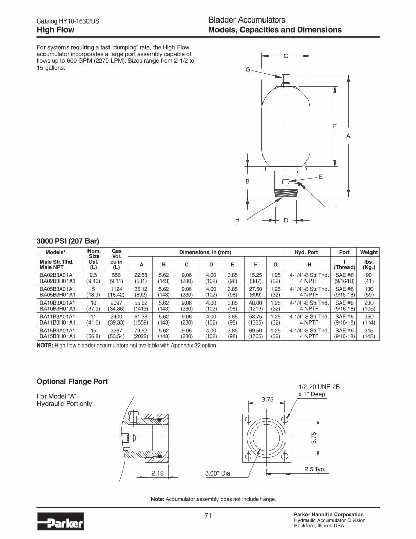
For systems requiring a fast “dumping” rate, the High Flowaccumulator incorporates a large port assembly capable offlows up to 600 GPM (2270 LPM). Sizes range from 2-1/2 to15 gallons.
Models1 Dimensions, in (mm) Hyd. Port Port Weight
Male Str. Thd. Gal. cu in A B C D E F G H I lbs.
Male NPT (L) (L) (Thread) (Kg.)BA02B3A01A1 2.5 556 22.88 5.62 9.06 4.00 3.85 15.25 1.25 4-1/4"-8 Str. Thd. SAE #6 90BA02B3H01A1 (9.46) (9.11) (581) (143) (230) (102) (98) (387) (32) 4 NPTF (9/16-18) (41)
BA05B3A01A1 5 1124 35.12 5.62 9.06 4.00 3.85 27.50 1.25 4-1/4"-8 Str. Thd. SAE #6 130BA05B3H01A1 (18.9) (18.42) (892) (143) (230) (102) (98) (699) (32) 4 NPTF (9/16-18) (59)
BA10B3A01A1 10 2097 55.62 5.62 9.06 4.00 3.85 48.00 1.25 4-1/4"-8 Str. Thd. SAE #6 230BA10B3H01A1 (37.9) (34.36) (1413) (143) (230) (102) (98) (1219) (32) 4 NPTF (9/16-18) (105)
BA11B3A01A1 11 2400 61.38 5.62 9.06 4.00 3.85 53.75 1.25 4-1/4"-8 Str. Thd. SAE #6 250BA11B3H01A1 (41.6) (39.33) (1559) (143) (230) (102) (98) (1365) (32) 4 NPTF (9/16-18) (114)
BA15B3A01A1 15 3267 79.62 5.62 9.06 4.00 3.85 69.50 1.25 4-1/4"-8 Str. Thd. SAE #6 315BA15B3H01A1 (56.8) (53.54) (2022) (143) (230) (102) (98) (1765) (32) 4 NPTF (9/16-18) (143)
3000 PSI (207 Bar)
Optional Flange Port
For Model “A”Hydraulic Port only
High Flow Models, Capacities and Dimensions
C
F
A
B
D
E
I
H
G
2.19 3.00" Dia.
3.75
3.75
2.5 Typ.
1/2-20 UNF-2Bx 1" Deep
Nom.Size
GasVol.
Note: Accumulator assembly does not include flange.
NOTE: High flow bladder accumulators not available with Appendix 22 option.
Catalog HY10-1630/US Bladder AccumulatorsIntroduction
72 Parker Hannifin CorporationHydraulic Accumulator DivisionRockford, Illinois USA
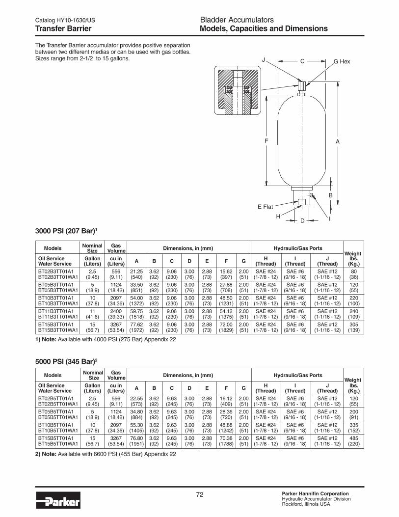
The Transfer Barrier accumulator provides positive separationbetween two different medias or can be used with gas bottles.Sizes range from 2-1/2 to 15 gallons.
Nominal GasModels Size Volume Dimensions, in (mm) Hydraulic/Gas Ports Weight
Oil Service Gallon cu in H I J lbs.Water Service (Liters) (Liters) A B C D E F G (Thread) (Thread) (Thread) (Kg.)BT02B3TT01A1 2.5 556 21.25 3.62 9.06 3.00 2.88 15.62 2.00 SAE #24 SAE #6 SAE #12 80BT02B3TT01WA1 (9.45) (9.11) (540) (92) (230) (76) (73) (397) (51) (1-7/8 - 12) (9/16 - 18) (1-1/16 - 12) (36)
BT05B3TT01A1 5 1124 33.50 3.62 9.06 3.00 2.88 27.88 2.00 SAE #24 SAE #6 SAE #12 120BT05B3TT01WA1 (18.9) (18.42) (851) (92) (230) (76) (73) (708) (51) (1-7/8 - 12) (9/16 - 18) (1-1/16 - 12) (55)
BT10B3TT01A1 10 2097 54.00 3.62 9.06 3.00 2.88 48.50 2.00 SAE #24 SAE #6 SAE #12 220BT10B3TT01WA1 (37.8) (34.36) (1372) (92) (230) (76) (73) (1231) (51) (1-7/8 - 12) (9/16 - 18) (1-1/16 - 12) (100)
BT11B3TT01A1 11 2400 59.75 3.62 9.06 3.00 2.88 54.12 2.00 SAE #24 SAE #6 SAE #12 240BT11B3TT01WA1 (41.6) (39.33) (1518) (92) (230) (76) (73) (1375) (51) (1-7/8 - 12) (9/16 - 18) (1-1/16 - 12) (109)
BT15B3TT01A1 15 3267 77.62 3.62 9.06 3.00 2.88 72.00 2.00 SAE #24 SAE #6 SAE #12 305BT15B3TT01WA1 (56.7) (53.54) (1972) (92) (230) (76) (73) (1829) (51) (1-7/8 - 12) (9/16 - 18) (1-1/16 - 12) (139)
3000 PSI (207 Bar)1
1) Note: Available with 4000 PSI (275 Bar) Appendix 22
Nominal GasModels Size Volume Dimensions, in (mm) Hydraulic/Gas Ports Weight
Oil Service Gallon cu in H I J lbs.Water Service (Liters) (Liters) A B C D E F G (Thread) (Thread) (Thread) (Kg.)BT02B5TT01A1 2.5 556 22.55 3.62 9.63 3.00 2.88 16.12 2.00 SAE #24 SAE #6 SAE #12 120BT02B5TT01WA1 (9.45) (9.11) (573) (92) (245) (76) (73) (409) (51) (1-7/8 - 12) (9/16 - 18) (1-1/16 - 12) (55)
BT05B5TT01A1 5 1124 34.80 3.62 9.63 3.00 2.88 28.36 2.00 SAE #24 SAE #6 SAE #12 200BT05B5TT01WA1 (18.9) (18.42) (884) (92) (245) (76) (73) (720) (51) (1-7/8 - 12) (9/16 - 18) (1-1/16 - 12) (91)
BT10B5TT01A1 10 2097 55.30 3.62 9.63 3.00 2.88 48.88 2.00 SAE #24 SAE #6 SAE #12 335BT10B5TT01WA1 (37.8) (34.36) (1405) (92) (245) (76) (73) (1242) (51) (1-7/8 - 12) (9/16 - 18) (1-1/16 - 12) (152)
BT15B5TT01A1 15 3267 76.80 3.62 9.63 3.00 2.88 70.38 2.00 SAE #24 SAE #6 SAE #12 485BT15B5TT01WA1 (56.7) (53.54) (1951) (92) (245) (76) (73) (1788) (51) (1-7/8 - 12) (9/16 - 18) (1-1/16 - 12) (220)
5000 PSI (345 Bar)2
2) Note: Available with 6600 PSI (455 Bar) Appendix 22
Models, Capacities and DimensionsTransfer Barrier
C G Hex
AF
B
E Flat
DH I
J

Catalog HY10-1630/UStontent Bladder AccumulatorsIntroduction
73 Parker Hannifin CorporationHydraulic Accumulator DivisionRockford, Illinois USA
Dimensions, inch (mm) Ports WeightGallon H I lbs.
Models (Liters) A B C D E F G (Thread) (Thread) (Kg.)
BG01B3T01A1 1 17.00 3.50 6.75 2.37 2.13 11.36 1.25 SAE #20 SAE #6 34(3.79) (432) (89) (171) (60) (54) (289) (32) (1-5/8 - 12) (9/16 - 18) (15)
BG02B3T01A1 2.5 21.25 3.62 9.06 3.00 2.88 15.62 1.25 SAE #24 SAE #6 80(9.46) (540) (92) (230) (76) (73) (397) (32) (1-7/8 - 12) (9/16 - 18) (36)
BG05B3T01A1 5 33.50 3.62 9.06 3.00 2.88 27.88 1.25 SAE #24 SAE #6 120(18.9) (851) (92) (230) (76) (73) (708) (32) (1-7/8 - 12) (9/16 - 18) (55)
BG10B3T01A1 10 54.00 3.62 9.06 3.00 2.88 43.38 1.25 SAE #24 SAE #6 220(37.9) (1372) (92) (230) (76) (73) (1102) (32) (1-7/8 - 12) (9/16 - 18) (100)
BG11B3T01A1 11 59.75 3.62 9.06 3.00 2.88 54.12 1.25 SAE #24 SAE #6 240(41.6) (1518) (92) (230) (76) (73) (1375) (32) (1-7/8 - 12) (9/16 - 18) (109)
BG15B3T01A1 15 77.62 3.62 9.06 3.00 2.88 72.00 1.25 SAE #24 SAE #6 305(56.8) (1972) (92) (230) (76) (73) (1829) (32) (1-7/8 - 12) (9/16 - 18) (139)
Where space does not permit the installation of the requiredaccumulator, a smaller accumulator may be used by connect-ing it to an auxiliary gas bottle(s) that may be located in somenearby spot where space is available. (See Large Gas Bottlesfor additional offerings and page 104 for sizing information.)Sizes range from 1 to 15 gallons.
3000 PSI (207 Bar)1
5000 PSI (345 Bar)2
Dimensions, inch (mm) Ports WeightGallon H I lbs.
Models (Liters) A B C D E F G (Thread) (Thread) (Kg.)
BG01B5T1A1 1 17.25 3.25 7.14 2.25 N/A 11.44 1.44 SAE #20 SAE #6 50(3.79) (438) (83) (181) (57) (291) (37) (1-5/8 - 12) (9/16 - 18) (23)
BG02B5T1A1 2.5 22.55 3.88 9.63 3.00 2.88 16.12 2.50 SAE #24 SAE #6 120(9.46) (573) (99) (245) (76) (73) (409) (64) (1-7/8 - 12) (9/16 - 18) (55)
BG05B5T1A1 5 34.80 3.88 9.63 3.00 2.88 28.36 2.50 SAE #24 SAE #6 200(18.9) (884) (99) (245) (76) (73) (720) (64) (1-7/8 - 12) (9/16 - 18) (91)
BG10B5T1A1 10 55.30 3.88 9.63 3.00 2.88 48.88 2.50 SAE #24 SAE #6 335(37.9) (1405) (99) (245) (76) (73) (1242) (64) (1-7/8 - 12) (9/16 - 18) (152)
BG15B5T1A1 15 76.80 3.88 9.63 3.00 2.88 70.38 2.50 SAE #24 SAE #6 485(56.8) (1951) (99) (245) (76) (73) (1788) (64) (1-7/8 - 12) (9/16 - 18) (220)
2) Note: Available with 6600 PSI (455 Bar) Appendix 22
1) Note: Available with 4000 PSI (275 Bar) Appendix 22
Models, Capacities and DimensionsGas Bottles
DE (Flat)
B
IH
AF
GC
NominalSize
NominalSize

Catalog HY10-1630/US Bladder AccumulatorsIntroduction
74 Parker Hannifin CorporationHydraulic Accumulator DivisionRockford, Illinois USA
Standard and Optional BladdersA variety of bladders are offered to suit a wide range of fluids and operating temperatures. The following table lists the optionalbladders available, their recommended operating temperature ranges, and the types of fluids that are generally compatible.
Recommended MaximumSeal Operating Temperature with General ApplicationCode Polymer Temperature Range Reduced Life & Compatibility*
01 Buna-Nitrile -20°F to 200°F 225°F Standard Compound – Compatible-29°C to 93°C 107°C with most mineral oil-based fluids
04 Hydrin -40°F to 225°F 250°F Compatible with most mineral oil-based fluids(Lo-Temp.) -40°C to 107°C 121°C with enhanced low temperature performance
06 Butyl -40°F to 200°F 300°F Compatible with most phosphate ester fluids-40°C to 93°C 149°C and some synthetic fluids
08 Ethylene -40°F to 200°F 300°F Compatible with some synthetic fluidsPropylene -40°C to 93°C 149°C and water
28 Fluorocarbon -10°F to 250°F 400°F Compatible with most mineral oil-based fluidsElastomer -23°C to 121°C 204°C at higher temperatures and some exotic fluids
*Note: Consult your local distributor or the factory for fluid compatibility information.Temperature ranges may vary depending upon the fluid used in the hydraulic system.
OptionsBladders, Water Service, Gas Valves
Water & Chemical Service Options (W)Bladder accumulators are available with a water and chemical resistance option. The (W) designation includes an internallySkotchkoted shell and stainless steel or electroless nickel plated port assembly. The Skotchkote offers added protection againstmore corrosive fluids.
Gas ValvesTwo types of gas valves are available on bladder accumula-tors. 3000 PSI rated models are offered with a cored gasvalve cartridge (cartridge type, 1 gal. & up, ISO-4570-8V1)as standard. 5000 PSI units are equipped with a highpressure cored gas valve cartridge (ISO-4570-8V1) with anoption of a heavy duty (military) poppet-type gas valvecartridge (Mil. Spec. MS28889-2).
Standard Gas Valve Military Gas Valve
#5 SAE THREAD1/2–20 UNF-2A
1/2–20 UNF-2A
L07421000*(3000 PSI)
L07688000*(4000 PSI)
L07440000*

Catalog HY10-1630/UStontent Bladder AccumulatorsIntroduction
75 Parker Hannifin CorporationHydraulic Accumulator DivisionRockford, Illinois USA
Bla
dder
Standard Port
Optional Ports
SAE Str. SAE 4-Bolt Undersize ISOThread Split Flange* NPTF NPTF BSPP 6149-1
Sizes Code T Code F Code U Code X Code R Code Y3000 PSI (207 Bar) Models
10 cu in SAE #8 – 3/4" Male – – M 8x1.51 pt., 1 qt. SAE #12 – 3/4" – G 3/4" M 27x2150 cu in SAE #16 – 1" – G 1" M 33x2
1 gal. SAE #20 1-1/4", Code 61 1-1/4" – G 1-1/4" M 42x22½ to 15 gal. SAE #24 2", Code 61 2" 1-1/4" G 2" M 48x2
5000 PSI (345 Bar) Models1 gal. SAE #20 1-1/4", Code 62 1-1/4" – G 1-1/4" M 42x2
2½ to 15 gal. SAE #24 1-1/2", Code 62 2" – G 2" M 48x2
SAE 4-Bolt Flange Port Dimensions
Standard Pressure – Code 61 (ISO 6162) – 3000 PSI (207 Bar)
High Pressure – Code 62 (ISO 6162) – 6000 PSI (410 Bar)
Flange SAE Flange Dimensions (in.) ISO 6162 Flange Dimensions (mm)Size A B C F G A B C F G1-1/4" 7/16 - 4 1.188 2.312 1-1/2 1.000 M10 30.2 58.7 32 25.4
2" 1/2 - 13 1.688 3.062 2 1.062 M12 42.9 77.8 51 26.9
Flange SAE Flange Dimensions (in.) ISO 6162 Flange Dimensions (mm)Size A B C F G A B C F G1-1/4" 1/2 - 13 1.250 2.625 1-1/4 1.000 M16 31.8 66.7 32 25.4
1-1/2" 5/8 - 11 1.438 3.125 1-1/2 1.375 M16 36.5 79.4 38 34.9
Standard and OptionalFluid PortsThe following standard and optional fluidports are offered on all Bottom Repair-able, Top Repairable, and TransferBarrier accumulators (for high flow ports,see High Flow). See How to Order at theend of this section for complete orderinginstructions.
Port AdaptersA wide variety of port adapters are offered to convert Parker’sstandard SAE port offerings to NPTF or smaller SAE port sizes.For a complete listing, see Accumulator Accessories.
OptionsPorts, Port Adapters
C
B
F
A (4 places) xG Min. Depth
*Split flanges not supplied.
Note: The dimensions shown on this chart are for the mating manifold. The flange halves are notsupplied with the accumulator.
Flange end for SAE J518 Code 61/62NOTE: 4-bolt split flange halves (notincluded).
Catalog HY10-1630/US Bladder AccumulatorsIntroduction
76 Parker Hannifin CorporationHydraulic Accumulator DivisionRockford, Illinois USA
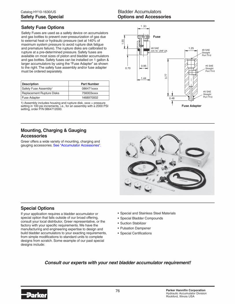
Safety Fuse OptionsSafety Fuses are used as a safety device on accumulatorsand gas bottles to prevent over-pressurization of gas dueto external heat or hydraulic pressure (set at 140% ofmaximum system pressure to avoid rupture disk fatigueand premature failure). The rupture disks are calibrated torupture at a pre-determined pressure. Safety fuses areavailable on most sizes of piston and bladder accumulatorsand gas bottles. Safety fuses can be installed on 1 gallon &larger accumulators by using the “Fuse Adapter” as shownto the right. The safety fuse assembly and/or fuse adaptermust be ordered separately.
Mounting, Charging & GaugingAccessoriesGreer offers a wide variety of mounting, charging andgauging accessories. See “Accumulator Accessories”.
Special OptionsIf your application requires a bladder accumulator orspecial option that falls outside of our broad offering,consult your local distributor, Greer representative, or thefactory with your specific requirements. We have themanufacturing and engineering expertise to design andbuild bladder accumulators to your exacting requirements,from simple modifications to standard units to completedesigns from scratch. Some example of our past specialdesigns include:
• Special and Stainless Steel Materials
• Special Bladder Compounds• Suction Stabilizer• Pulsation Dampener
• Special Certifications
Consult our experts with your next bladder accumulator requirement!
Description Part Number Safety Fuse Assembly1 086471xxxx
Replacement Rupture Disks 756003xxxx
Fuse Adapter 1468970002
1) Assembly includes housing and rupture disk, xxxx = pressuresetting in 100 psi increments, i.e., for an assembly with a 2000 PSIsetting, order P/N 0864712000.
Options and AccessoriesSafety Fuse, Special
1.25#8 SAEStraightPort Th’d
#5 SAEStraightPort Th’d
#5 SAEStraightPort Th’d0.48
3.77
Fuse Adapter
1.44
0.950.70
1.55
Fuse
#8 SAE3/4-16 UNF-2A

Catalog HY10-1630/UStontent Bladder AccumulatorsIntroduction
77 Parker Hannifin CorporationHydraulic Accumulator DivisionRockford, Illinois USA
Bla
dder
A full range of genuine Greer replacement bladder kits are available to bring your accumulator back to original condition shouldreplacement become necessary. All bladder kits include port o-ring, backup seals and gas valves with secondary seals.NOTE: Part numbers shaded in gray will be phased out.
Replacement KitsBladder Kits
Bladder & Seal Compound
Group 01 Group 04 Group 06 Group 08 Group 28Size Brand Nitrile (NBR) Hydrin Butyl EPR Fluorocarbon
3,000 PSI Standard Bladder Kits (Top & Bottom Repairable)
10 Cu. In. Greer 702900 702902 702903 702904 702906
Parker 0850693C10 0856663C10 0850703C10 0851053C10 0851043C10
1 Pt. Greer 702914 702916 702917 702918 702920
Parker 0850693001 0856663001 0850703001 0851053001 0851043001
1 Qt. Greer 702928 702930 702931 702932 702934
Parker 0850693002 0856663002 0850703002 0851053002 0851043002
150 Cu. In. Greer 702942 702944 702945 702946 702948
Parker 0850693006 0856663006 0850703006 0851053006 0851043006
1 Gal. Greer 702956 702958 702959 702960 702962
Parker 0850693010 0856663010 0850703010 0851053010 0851043010
2 1/2 Gal. Greer 702970 702972 702973 702974 702976
Parker 0850693025 0856663025 0850703025 0851053025 0851043025
5 Gal. Greer 702984 702986 702987 702988 702990
Parker 0850693050 0856663050 0850703050 0851053050 0851043050
10 Gal. Greer 702998 703000 703001 703002 703004
Parker 0850693100 0856663100 0850703100 0851053100 0851043100
11 Gal. Greer 703012 703014 703015 703016 703018
Parker 0850693110 0856663110 0850703110 0851053110 0851043110
15 Gal. Greer 703026 703028 703029 703030 703032
Parker 0850693150 0856663150 0850703150 0851053150 0851043150
25 Gal. Greer 703340 704008 704009 703341 703342
Parker 0850693250 0856663250 0850703250 0851053250 0851043250
40 Gal. Greer 703346 704014 704015 703347 703348
Parker 0850693400 0856663400 0850703400 0851053400 0851043400
5,000 PSI Bottom Repairable Bladder Kits (2" Valve Stem - New Style)
1 Gal. Greer 8706135010 8706175010 8706145010 8706145010 8706155010
7/8" ∅ Stem Parker 8706135010 8706175010 8706145010 8706145010 8706155010
1 Gal. Greer 704060 704062 704063 704064 704066
1" ∅ Stem Parker 0850695010 0856665010 080705010 0851055010 0851045010
2 1/2 Gal. Greer 706000 706002 706003 706004 706006
Parker 0861905025 0861945025 0861915025 0861935025 0861925025
5 Gal. Greer 706010 706012 706013 706014 706016
Parker 0861905050 0861945050 0861915050 0861935050 0861925050
10 Gal. Greer 706020 706022 706023 706024 706026
Parker 0861905100 0861945100 0861915100 0861935100 0861925100
15 Gal. Greer 706030 706032 706033 706034 706036
Parker 0861905150 0861945150 0861915150 0861935150 0861925150
5,000 PSI Bottom Repairable Bladder Kits (7/8" Valve Stem - Old Style)
2 1/2 Gal. Parker 0850695025 0856665025 0850705025 0851055025 0851045025
5 Gal. Parker 0850695050 0856665050 0850705050 0851055050 0851045050
10 Gal. Parker 0850695100 0856665100 0850705100 0851055100 0851045100
15 Gal. Parker 0850695150 0856665150 0850705150 0851055150 0851045150

Catalog HY10-1630/UStontent Bladder AccumulatorsIntroduction
79 Parker Hannifin CorporationHydraulic Accumulator DivisionRockford, Illinois USA
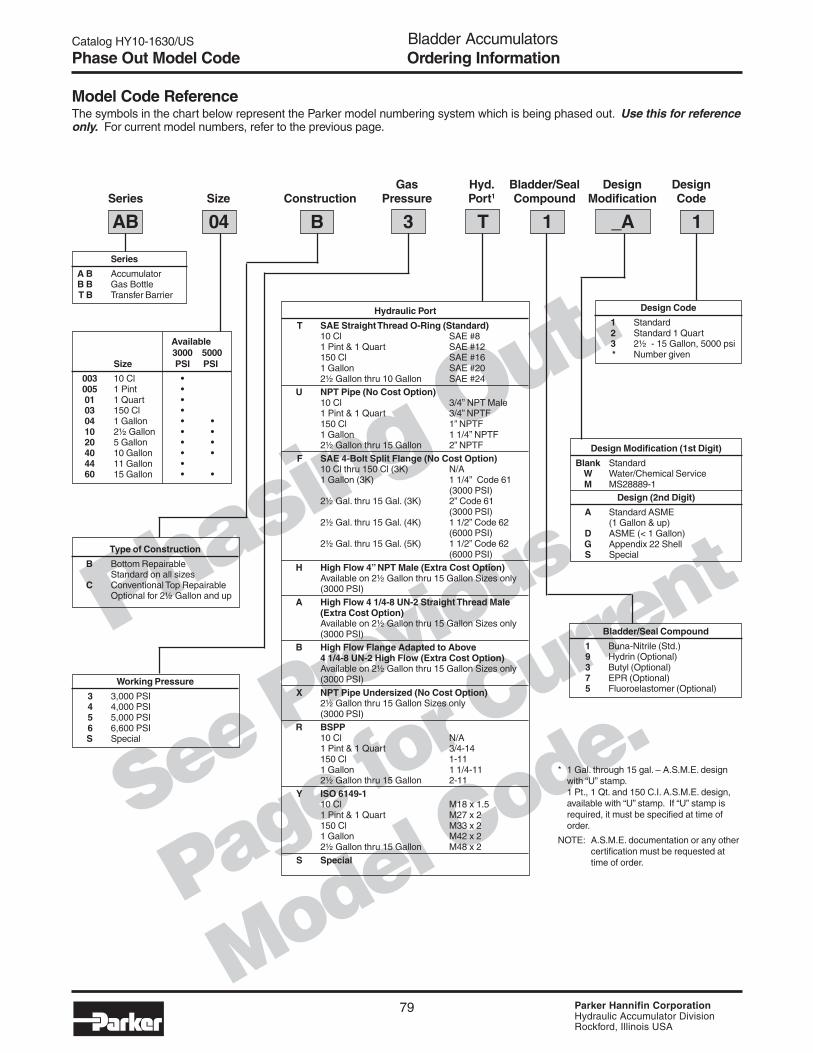
Phasing Out.
See Previous
Page for Curre
nt
Model Code.
Gas Hyd. Bladder/Seal Design DesignSeries Size Construction Pressure Port1 Compound Modification Code
AB 04 B T 1 _A 1
Series
A B AccumulatorB B Gas BottleT B Transfer Barrier
3
Available3000 5000
Size PSI PSI
003 10 Cl •005 1 Pint •01 1 Quart •03 150 Cl •04 1 Gallon • •10 2½ Gallon • •20 5 Gallon • •40 10 Gallon • •44 11 Gallon •60 15 Gallon • •
Type of Construction
B Bottom RepairableStandard on all sizes
C Conventional Top RepairableOptional for 2½ Gallon and up
Working Pressure
3 3,000 PSI4 4,000 PSI5 5,000 PSI6 6,600 PSIS Special
Hydraulic Port
T SAE Straight Thread O-Ring (Standard)10 Cl SAE #81 Pint & 1 Quart SAE #12150 Cl SAE #161 Gallon SAE #202½ Gallon thru 10 Gallon SAE #24
U NPT Pipe (No Cost Option)10 Cl 3/4” NPT Male1 Pint & 1 Quart 3/4” NPTF150 Cl 1” NPTF1 Gallon 1 1/4” NPTF2½ Gallon thru 15 Gallon 2” NPTF
F SAE 4-Bolt Split Flange (No Cost Option)10 Cl thru 150 Cl (3K) N/A1 Gallon (3K) 1 1/4” Code 61
(3000 PSI)2½ Gal. thru 15 Gal. (3K) 2” Code 61
(3000 PSI)2½ Gal. thru 15 Gal. (4K) 1 1/2” Code 62
(6000 PSI)2½ Gal. thru 15 Gal. (5K) 1 1/2” Code 62
(6000 PSI)H High Flow 4” NPT Male (Extra Cost Option)
Available on 2½ Gallon thru 15 Gallon Sizes only(3000 PSI)
A High Flow 4 1/4-8 UN-2 Straight Thread Male(Extra Cost Option)Available on 2½ Gallon thru 15 Gallon Sizes only(3000 PSI)
B High Flow Flange Adapted to Above4 1/4-8 UN-2 High Flow (Extra Cost Option)Available on 2½ Gallon thru 15 Gallon Sizes only(3000 PSI)
X NPT Pipe Undersized (No Cost Option)2½ Gallon thru 15 Gallon Sizes only(3000 PSI)
R BSPP10 Cl N/A1 Pint & 1 Quart 3/4-14150 Cl 1-111 Gallon 1 1/4-112½ Gallon thru 15 Gallon 2-11
Y ISO 6149-110 Cl M18 x 1.51 Pint & 1 Quart M27 x 2150 Cl M33 x 21 Gallon M42 x 22½ Gallon thru 15 Gallon M48 x 2
S Special
Design Modification (1st Digit)
Blank StandardW Water/Chemical ServiceM MS28889-1
Design (2nd Digit)
A Standard ASME(1 Gallon & up)
D ASME (< 1 Gallon)G Appendix 22 ShellS Special
Design Code
1 Standard2 Standard 1 Quart3 2½ - 15 Gallon, 5000 psi* Number given
* 1 Gal. through 15 gal. – A.S.M.E. designwith “U” stamp.1 Pt., 1 Qt. and 150 C.I. A.S.M.E. design,available with “U” stamp. If “U” stamp isrequired, it must be specified at time oforder.
NOTE: A.S.M.E. documentation or any othercertification must be requested attime of order.
Bladder/Seal Compound
1 Buna-Nitrile (Std.)9 Hydrin (Optional)3 Butyl (Optional)7 EPR (Optional)5 Fluoroelastomer (Optional)
Phase Out Model Code
Model Code ReferenceThe symbols in the chart below represent the Parker model numbering system which is being phased out. Use this for referenceonly. For current model numbers, refer to the previous page.
Ordering Information

Catalog HY10-1630/US Bladder AccumulatorsIntroduction
80 Parker Hannifin CorporationHydraulic Accumulator DivisionRockford, Illinois USA
Notes