
BIOS SECTION N3530 - Fujitsu Global · 2010-04-09 · BIOS SECTION N3530. 2 ... This will open the...
22
BIOS SECTION N3530
Transcript of BIOS SECTION N3530 - Fujitsu Global · 2010-04-09 · BIOS SECTION N3530. 2 ... This will open the...

BIOSSECTION
N3530

L i f e B o o k N S e r i e s N o t e b o o k B I O S
2
N Series BIOSBIOS SETUP UTILITYThe BIOS Setup Utility is a program that sets up the operating environment for your notebook. Your BIOSis set at the factory for normal operating conditions, therefore there is no need to set or change the BIOS environment to operate your notebook.
The BIOS Setup Utility configures:
■ Device control feature parameters, such as changingI/O addresses and boot devices.
■ System Data Security feature parameters, such as passwords.
Entering the BIOS Setup Utility
To enter the BIOS Setup Utility do the following:
1. Turn on or restart your notebook.
2. Press the [F2] key once the Fujitsu logo appears on the screen. This will open the main menu of the BIOS Setup Utility with the current settings displayed.
3. Press the arrow keys to scroll through the other setup menus to review or alter the current settings.
Navigating Through The Setup Utility
The BIOS setup utility consists of six menus: Informa-tion, Main, Advanced, Security, Boot, and Exit. This document explains each menu in turn, including all submenus and setup items.
The following procedures allow you to navigate the setup utility menus:
1. To select a menu, use the cursor keys:
2. To select a field within a menu or a submenu, use the cursor keys:
3. To select the different values for each field, press the [Spacebar] or [+] to change to the next higher selection and [F5] or [-] to go to the next lower selection.
4. To activate a submenu press the [Enter] key.
5. To return to a menu from a submenu, pressthe [Esc] key.
6. To go to the Exit menu from any other menu,
press the [Esc] key.
7. Pressing the [F9] key resets all items in the BIOS to the default values.
8. Pressing the [F10] key saves the current configura-tion and exits the BIOS Setup Utility. You will be asked to verify this selection before it is executed.
9. Pressing the [F1] key gives you a general help screen.
Entering the Setup Utility After a Configuration Change or System Failure
If there has been a change in the system configuration that does not agree with the parameter settings storedin your BIOS memory, or there is a failure in the system, the system beeps and/or displays an error message after the Power On Self Test (POST). If the failure is nottoo severe, it will give you the opportunity to modify the settings of the setup utility, as described in the following steps:
1. When you turn on or restart the computer there is a beep and/or the following message appears on the screen:
Error message - please run SETUP program Press <F1> key to continue, <F2> to run SETUP
2. If an error message is displayed on the screen, and you want to continue with the boot process and start
the operating system anyway, press the [F1] key.
[ ], [ ].
[ ], [ ].
■ Selecting a field causes a help message about that field to be displayed on the right-hand side of the screen.
■ Pressing the Enter key with the highlight on a selection that is not a submenu or auto selection will cause a list of all options for that item to be displayed. Pressing the Enter key again will select the highlighted choice.
■ If your notebook emits a series of beeps that sounds like a code and the display is blank, refer to the Troubleshooting sec-tion of your system Use’s Guide. The Troubleshooting Section includes a list of error messages and their meanings.
■ If your data security settings require it, you may be asked for a password before the operating system will be opened.

B I O S S e t u p U t i l i t y
3
3. If an error message is displayed on the screen, and you want to enter the setup utility, press the [F2] key.
4. When the setup utility starts with a fault present, the system displays the following message:
Warning!
Error message[Continue]
5. Press any key to enter the setup utility. The system will then display the Main Menu with current parameters values.

4
L i f e B o o k N S e r i e s N o t e b o o k B I O S
INFORMATION MENU - DISPLAYS BASIC SYSTEM INFORMATIONThe Information menu is a display-only screen that provides the configuration information for your note-book.
The following table shows the names of the menu fields for the Information menu and the information displayed in those fields. These fields are for information purposes only, and cannot be modified by the user.
Figure 1. Information Menu
The information, including CPU type and speed, and total memory, displayed on this screen varies according to the unit you purchased.
Table 1: Fields, Options and Defaults for the Information MenuNote that the parameters listed in the following table may be different, depending upon the system configuration.
Menu Field Default Menu Field Default
BIOS Version: 1.XX L2 Cache RAM: 2048 KB
BIOS Date: 01/XX/2006 Total (Memory): 512 MB DDR2
BIOS Area: E000h – FFFFh Slot 1: 512 MB DDR2
CPU: Genuine Intel(R) CPU T2300 @ 1.66GHz Slot 2: None
L1 Cache RAM: 128 KB Asset Number: None
InsydeH20 Setup Utility
Information
SystemBIOS Version: 1.09BIOS Date: 03/13/2006BIOS Area: E000h - FFFFh
CPU Genuine Intel(R) CPU T2300 @ 1.66GHzL1 Cache RAM: 128 KBL2 Cache RAM: 2048 KB
MemoryTotal: 512 MB DDR2 Slot 1: 512 MB DDR2 Slot 2: None
Asset Number: None
▲
Up/Dn Select Boot Device<> Select Screen
Select ItemEnter Select SubmenuF1 = HelpF9 = Setup DefaultsF10 = Save and ExitEsc = Exit

M a i n M e n u
5
MAIN MENU – SETTING STANDARD SYSTEM PARAMETERSThe Main Menu allows you to set or view the current system parameters. (See Navigating Through The Setup Utility on page 2 for more information.)
The following tables show the names of the menu fields for the Main menu and its submenus, all of the options for each field, the default settings and a description of
the field’s function and any special information needed to help understand the field’s use.
Figure 2. Main Menu
System Time and System Date can also be set from your operating system without using the setup utility. Use the Date and Time icon on your Windows Control panel or type time or date from the MS-DOS prompt.
Table 2: Fields, Options and Defaults for the Main MenuNote that the parameters listed in the following table may vary depending upon your system’s configuration.
Menu Field Options Default Description
System Time: –— –— Sets and displays the current time. Time is in a 24 hour formatof hours:minutes:seconds with 2 digits for each. (HH:MM:SS). Example: 16:45:57. You may change each segment of the time separately. Move between the seg-ments with the [Tab] key. Change the setting using the Page Up and Page Down buttons.
System Date: –— –— Sets and displays the current date. Date is in a month/day/year numeric format with 2 digits each for month and day and 4 digits for year. (MM/DD/YYYY) for example: 03/20/1998. You may change each segment of the date separately. Move between the segments with the [Tab] key. Change the setting using the page Up and Page Down buttons.
InsydeH20 Setup Utility
Information Main Advanced Security Boot Exit
Adjust calendar clock.
<Pg Up> and <Pg Dn>keys increase anddecrease setting.
Press <Tab> to changenext item.
System Time: [14:57:01]System Date: [03/28/2006]
Drive0 <Auto> [FUJITSU MHV2100BH ]Drive1 <Auto>[DV-W28EAD ]
Language: <English>
▲
Up/Dn Select Boot Device<> Select Screen
Select ItemEnter Select SubmenuF1 = HelpF9 = Setup DefaultsF10 = Save and ExitEsc = Exit

L i f e B o o k N S e r i e s N o t e b o o k B I O S
6
Exiting from Main MenuWhen you have finished setting the parameters on this menu, you can either exit from the setup utility, or move to another menu. If you wish to exit from the setup utility, press the [Esc] key or use the cursor keys to go to the Exit menu. If you wish to move to another menu, use the cursor keys.
Drive0 ■ Auto■ Disabled
[Auto] {Auto] automatically selects the Drive0 ATA/ATAPI device type. To change the selection, press the [Enter] key to display the selections. Select [Auto] to have the type automatically configured by the BIOS at POST. Select [Disabled] if you don’t want to select a primary master.
Drive1 ■ Auto■ Disabled
[Auto] {Auto] automatically selects the Drive1 ATA/ATAPI device type. To change the selection, press the [Enter] key to display the selections. Select [Auto] to have the type automatically configured by the BIOS at POST. Select [Disabled] if you don’t want to select a primary master.
Language: ___ [English] The default setting is English.
Table 2: Fields, Options and Defaults for the Main MenuNote that the parameters listed in the following table may vary depending upon your system’s configuration.
Menu Field Options Default Description

A d v a n c e d M e n u
7
ADVANCED MENU – SETTING DEVICE FEATURE CONTROLSThe Advanced Menu allows you to:
■ Set the keyboard Numlock feature.■ Select between the display panel and an external
CRT display or video projector.■ Enable or disable compensation for your display.■ Enables or disables the internal controllers.■ Configure CPU and USB features in your system.
(See Navigating Through The Setup Utility on page 2 for more information.)
The following tables show the names of the menu fields for the Advanced Menu and its submenus, all of the options for each field, the default settings and a descrip-tion of the field’s function and any special information needed to help understand the field’s use.
Figure 3. Advanced Menu
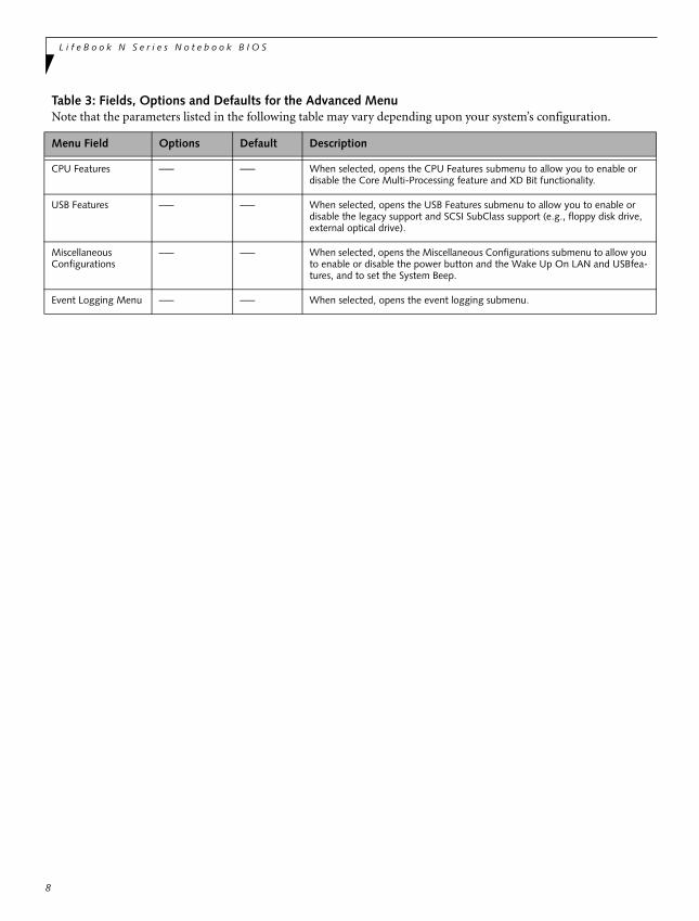
Table 3: Fields, Options and Defaults for the Advanced MenuNote that the parameters listed in the following table may vary depending upon your system’s configuration.
Menu Field Options Default Description
Keyboard Numlock ■ Disabled■ Enabled
[Disabled] When enabled or disabled, turns NumLock on and off, respectively.
Video Features –— –— When selected, opens the Video Features submenu, which allows setting of the display parameters, including routing of video signals to different displays.
Internal Device Configurations
–— –— When selected, opens the Internal Device Configuration submenu, which allows enabling or disabling the Serial ATA, IDE, and WLAN Controllers.
InsydeH20 Setup Utility
Information Main Advanced Security Boot Exit
Selects Power-On Statefor Numlock.
▲
Up/Dn Select Boot Device<> Select Screen
Select ItemEnter Select SubmenuF1 = HelpF9 = Setup DefaultsF10 = Save and ExitEsc = Exit
▲ ▲
▲ ▲
▲
Keyboard Numlock <Disabled>Video FeaturesInternal Device ConfigurationsCPU FeaturesUSB FeaturesMiscellaneous ConfigurationsEvent Logging Menu
▲
L i f e B o o k N S e r i e s N o t e b o o k B I O S
8
CPU Features –— –— When selected, opens the CPU Features submenu to allow you to enable or disable the Core Multi-Processing feature and XD Bit functionality.
USB Features –— –— When selected, opens the USB Features submenu to allow you to enable or disable the legacy support and SCSI SubClass support (e.g., floppy disk drive, external optical drive).
MiscellaneousConfigurations
–— –— When selected, opens the Miscellaneous Configurations submenu to allow you to enable or disable the power button and the Wake Up On LAN and USBfea-tures, and to set the System Beep.
Event Logging Menu –— –— When selected, opens the event logging submenu.
Table 3: Fields, Options and Defaults for the Advanced MenuNote that the parameters listed in the following table may vary depending upon your system’s configuration.
Menu Field Options Default Description
A d v a n c e d M e n u
9
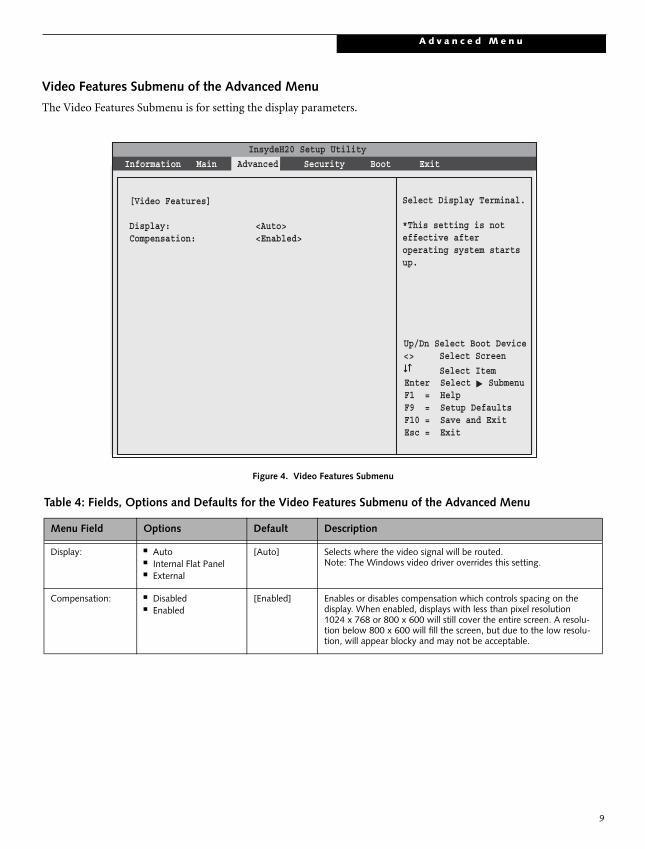
Video Features Submenu of the Advanced Menu
The Video Features Submenu is for setting the display parameters.
Figure 4. Video Features Submenu
Table 4: Fields, Options and Defaults for the Video Features Submenu of the Advanced Menu
Menu Field Options Default Description
Display: ■ Auto■ Internal Flat Panel■ External
[Auto] Selects where the video signal will be routed.Note: The Windows video driver overrides this setting.
Compensation: ■ Disabled■ Enabled
[Enabled] Enables or disables compensation which controls spacing on thedisplay. When enabled, displays with less than pixel resolution1024 x 768 or 800 x 600 will still cover the entire screen. A resolu-tion below 800 x 600 will fill the screen, but due to the low resolu-tion, will appear blocky and may not be acceptable.
InsydeH20 Setup Utility
Information Main Advanced Security Boot Exit▲
Up/Dn Select Boot Device<> Select Screen
Select ItemEnter Select SubmenuF1 = HelpF9 = Setup DefaultsF10 = Save and ExitEsc = Exit
[Video Features]
Display: <Auto>Compensation: <Enabled>
Select Display Terminal.
*This setting is noteffective afteroperating system starts up.

L i f e B o o k N S e r i e s N o t e b o o k B I O S
Internal Device Configurations Submenu of the Advanced Menu
The Internal Device Configuration submenu allows the user to configure other internal devices.
Figure 5. Internal Device Configuration Submenu
Table 5: Fields, Options and Defaults for the Internal Device Configuration Submenu of the Advanced Menu
Menu Field Options Default Description
Serial ATA Controller: ■ Disabled■ Enabled
[Enabled] Enables or disables the Serial ATA port.
AHCI Configuration: ■ Disabled■ Enabled
[Enabled] Enables or disables the AHCI (Advanced Host Controller Interface).
IDE Controller: ■ Disabled■ Enabled
[Enabled] Enables or disables selected IDE devices.
InsydeH20 Setup Utility
Information Main Advanced Security Boot Exit▲
Up/Dn Select Boot Device<> Select Screen
Select ItemEnter Select SubmenuF1 = HelpF9 = Setup DefaultsF10 = Save and ExitEsc = Exit
[Internal Device Configurations]
Serial ATA Controller: <Enabled> AHCI Configuration: <Enabled>IDE Controller: <Enabled>
[Disabled]Serial ATA port isdisabled.
[Enabled]Serial ATA port isenabled.
10

A d v a n c e d M e n u
11
CPU Features Submenu of the Advanced Menu
The CPU Features Submenu provides options for enabling or disabling the SpeedStep® Technology feature.
Figure 6. CPU Features Submenu
Table 6: Fields, Options and Defaults for the CPU Features Submenu of the Advanced Menu
Menu Field Options Default Description
Core Multi-Processing
• Disabled• Enabled
[Enabled] Enables or disables the multi-processing functionality of the Core processor.
XD Bit functionality:
• Disabled• Enabled
[Enabled] Allows the user to enable and disable the Execute Disable Bit functionality. Execute Disable Bit allows the processor to classify areas in memory where application code can and cannot execute. In the event an internet worm attempts to insert code in the buffer, the processor disables code execution to prevent damage or worm propagation.
InsydeH20 Setup Utility
Information Main Advanced Security Boot Exit▲
Up/Dn Select Boot Device<> Select Screen
Select ItemEnter Select SubmenuF1 = HelpF9 = Setup DefaultsF10 = Save and ExitEsc = Exit
[CPU Features]
Core Multi-Processing: <Enabled>XD Bit functionality: <Enabled>
Select Core Multi-Processingenabled or disabled.
L i f e B o o k N S e r i e s N o t e b o o k B I O S
12
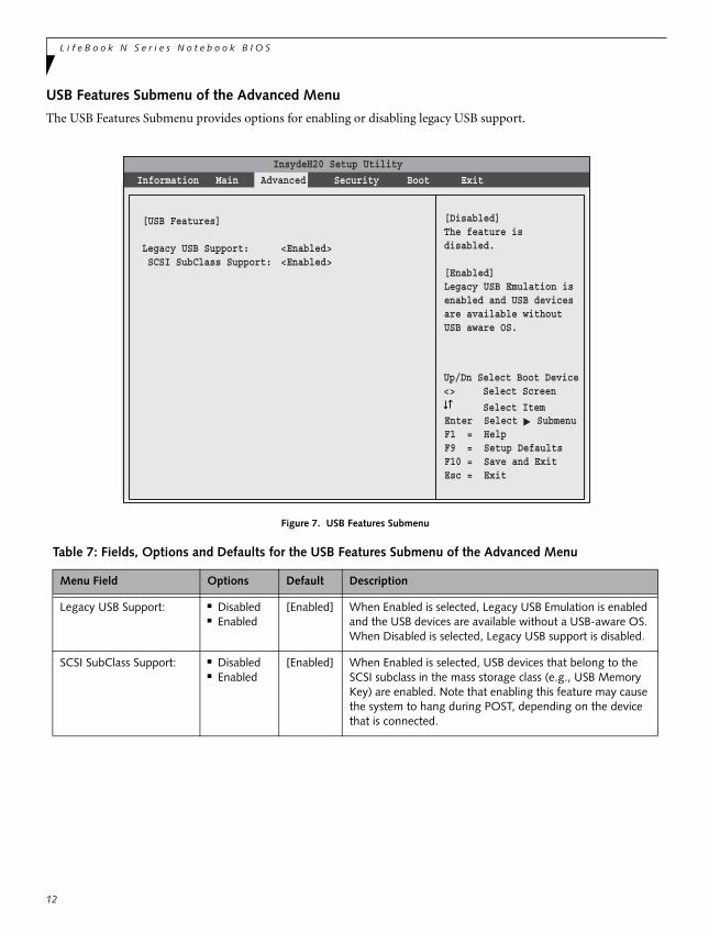
USB Features Submenu of the Advanced Menu
The USB Features Submenu provides options for enabling or disabling legacy USB support.
Figure 7. USB Features Submenu
Table 7: Fields, Options and Defaults for the USB Features Submenu of the Advanced Menu
Menu Field Options Default Description
Legacy USB Support: ■ Disabled■ Enabled
[Enabled] When Enabled is selected, Legacy USB Emulation is enabled and the USB devices are available without a USB-aware OS. When Disabled is selected, Legacy USB support is disabled.
SCSI SubClass Support: ■ Disabled■ Enabled
[Enabled] When Enabled is selected, USB devices that belong to the SCSI subclass in the mass storage class (e.g., USB Memory Key) are enabled. Note that enabling this feature may cause the system to hang during POST, depending on the device that is connected.
InsydeH20 Setup Utility
Information Main Advanced Security Boot Exit▲
Up/Dn Select Boot Device<> Select Screen
Select ItemEnter Select SubmenuF1 = HelpF9 = Setup DefaultsF10 = Save and ExitEsc = Exit
[USB Features]
Legacy USB Support: <Enabled> SCSI SubClass Support: <Enabled>
[Disabled]The feature is disabled.
[Enabled]Legacy USB Emulation isenabled and USB devicesare available withoutUSB aware OS.

A d v a n c e d M e n u
13
Miscellaneous Configurations Submenu of the Advanced Menu
The Miscellaneous Configurations Submenu provides options for enabling or disabling the power button and the Wake Up On LAN or USB features, and for setting the System Beep.
Figure 8. Miscellaneous Configurations Submenu
Table 8: Fields, Options and Defaults for the Miscellaneous Configurations Submenu of the Advanced Menu
Menu Field Options Default Description
Power Button: ■ Disabled■ Enabled
[Disabled] Selecting Disabled disables the power button. Selecting Enabled allows you to turn off system power with the power button.
Wake up on LAN: ■ Disabled■ Enabled
[Disabled] Selecting Enabled allows the system to wake up when the internal LAN device receives a specific signal while in power-off state. Selecting Disabled disables this feature.
Wake up on USB Device: ■ Disabled■ Enabled
[Disabled] Selecting Enabled allows the system to be awakened from Standby mode by a USB device on a specific port. Selecting Disabled disables this feature.
System Beep: ■ Disabled■ Enabled
[Enabled] Allows you to set or disable the system beep. This item is enabled by default.
InsydeH20 Setup Utility
Information Main Advanced Security Boot Exit▲
Up/Dn Select Boot Device<> Select Screen
Select ItemEnter Select SubmenuF1 = HelpF9 = Setup DefaultsF10 = Save and ExitEsc = Exit
[Miscellaneous Configurations]
Power Button: <Disabled>Wake up on LAN: <Disabled>Wake up on USB Device: <Disabled>System Beep: <Enabled>
Configures the powerbutton.*ACPI OS ignores thissetting.
L i f e B o o k N S e r i e s N o t e b o o k B I O S
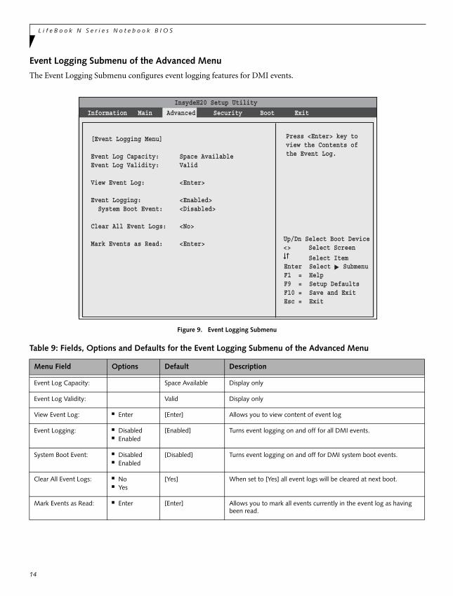
Event Logging Submenu of the Advanced Menu
The Event Logging Submenu configures event logging features for DMI events.
Figure 9. Event Logging Submenu
Table 9: Fields, Options and Defaults for the Event Logging Submenu of the Advanced Menu
Menu Field Options Default Description
Event Log Capacity: Space Available Display only
Event Log Validity: Valid Display only
View Event Log: ■ Enter [Enter] Allows you to view content of event log
Event Logging: ■ Disabled■ Enabled
[Enabled] Turns event logging on and off for all DMI events.
System Boot Event: ■ Disabled■ Enabled
[Disabled] Turns event logging on and off for DMI system boot events.
Clear All Event Logs: ■ No■ Yes
[Yes] When set to [Yes] all event logs will be cleared at next boot.
Mark Events as Read: ■ Enter [Enter] Allows you to mark all events currently in the event log as having been read.
InsydeH20 Setup Utility
Information Main Advanced Security Boot Exit▲
Up/Dn Select Boot Device<> Select Screen
Select ItemEnter Select SubmenuF1 = HelpF9 = Setup DefaultsF10 = Save and ExitEsc = Exit
[Event Logging Menu]
Event Log Capacity: Space AvailableEvent Log Validity: Valid
View Event Log: <Enter>
Event Logging: <Enabled> System Boot Event: <Disabled>
Clear All Event Logs: <No>
Mark Events as Read: <Enter>
Press <Enter> key toview the Contents ofthe Event Log.
14
S e c u r i t y M e n u
15
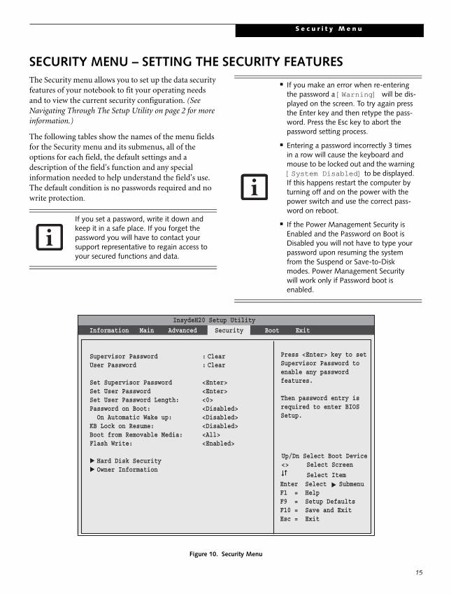
SECURITY MENU – SETTING THE SECURITY FEATURESThe Security menu allows you to set up the data security features of your notebook to fit your operating needs and to view the current security configuration. (See Navigating Through The Setup Utility on page 2 for more information.)
The following tables show the names of the menu fields for the Security menu and its submenus, all of the options for each field, the default settings and a description of the field's function and any special information needed to help understand the field's use. The default condition is no passwords required and no write protection.
Figure 10. Security Menu
If you set a password, write it down and keep it in a safe place. If you forget the password you will have to contact your support representative to regain access to your secured functions and data.
■ If you make an error when re-entering the password a [Warning] will be dis-played on the screen. To try again press the Enter key and then retype the pass-word. Press the Esc key to abort the password setting process.
■ Entering a password incorrectly 3 times in a row will cause the keyboard and mouse to be locked out and the warning [System Disabled] to be displayed. If this happens restart the computer by turning off and on the power with the power switch and use the correct pass-word on reboot.
■ If the Power Management Security is Enabled and the Password on Boot is Disabled you will not have to type your password upon resuming the system from the Suspend or Save-to-Disk modes. Power Management Security will work only if Password boot is enabled.
InsydeH20 Setup Utility
Information Main Advanced Security Boot Exit
▲
Up/Dn Select Boot Device<> Select Screen
Select ItemEnter Select SubmenuF1 = HelpF9 = Setup DefaultsF10 = Save and ExitEsc = Exit
Supervisor Password : ClearUser Password : Clear
Set Supervisor Password <Enter> Set User Password <Enter>Set User Password Length: <0>Password on Boot: <Disabled> On Automatic Wake up: <Disabled>KB Lock on Resume: <Disabled>Boot from Removable Media: <All>Flash Write: <Enabled>
Hard Disk Security Owner Information
Press <Enter> key to setSupervisor Password toenable any passwordfeatures.
Then password entry isrequired to enter BIOSSetup.
▲▲

L i f e B o o k N S e r i e s N o t e b o o k B I O S
16
Exiting from the Security Menu
When you have finished setting the parameters on the Security Menu, you can either exit from setup utility or move to another menu. If you wish to exit from setup utility, press the Esc key to go to the Exit Menu. If you wish to move to another menu, use the cursor keys.
Table 10: Fields, Options and Defaults for the Security Menu
Menu Field Options Default Description
SupervisorPassword is:
–— Clear A display-only field. Set is displayed when the system supervisor password is set and Clear when it is not.
User Password is: –— Clear A display-only field. Set is displayed when the general userpassword is set, and Clear when it is not.
Set Supervisor Password
–— [Enter] Sets, changes or cancels the Supervisor Password. Supervisor’s Password may be up to seven characters long and must include only letters or num-bers (no symbols). Passwords are NOT case- sensitive. To cancel a pass-word press the Enter key instead of entering characters in the Enter New Password field and in the Re-enter New Password field. When a Supervi-sor Password is set it must be used to access the BIOS setup utility.
Set User Password –— [Enter] This field can only be accessed if the Supervisor Password is set. Sets, changes or cancels the User Password. The User Password may be up to seven characters long and must include only letters or numbers (no symbols). Passwords are NOT case-sensitive. To cancel a password press the Enter key instead of entering characters in the Enter New Password field and in the Re-enter New Password field. When a User Password is set it must be used to access the BIOS setup utility.
Set User Password Length:
–— [0] Supervisor can set password length (0 to 8) for user password. User cannot set a password shorter than the minimum length.
Password on Boot: ■ Disabled■ First Boot■ Every Boot
[Disabled] When set to First Boot, a password (User or Supervisor) is required just once after the Power On Self Test (POST) before the operating system will be read from a disk. When set to Every Boot, a password (User or Supervisor) is required every time after the Power On Self Test (POST) before the operating system will be read from a disk. When set to Dis-abled no password is required.
On Automatic Wake up:
■ Disabled■ Enabled
[Disabled] When set to Disabled, it is not necessary to enter a password to wake up from LAN or Real Time Clock (RTC). When Enabled, it is still necessary to enter a password after automatic wake-up.
KB Lock on Resume:
■ Disabled■ Enabled
[Disabled] When set to Enabled, the PS/2 mouse and keyboard inputs are locked out upon Resume from Suspend or Save to Disk mode until you enter the password. When set to Disabled no password is required. If no Supervisor Password is set, this feature is not available and no password is required.
Boot from Removable Media:
■ All■ Supervisor only
[All] When All is selected, booting from removable media is not restricted. When Supervisor Only is selected, only the Supervisor (i.e., the user who enters Supervisor password), can boot from removable media.
Flash Write: ■ Disabled■ Enabled
[Enabled] When set to [Disabled], the BIOS Flash memory is write protected.
Hard Disk Security: –— –— Configures hard disk security features
Owner Information:
–— –— Sets Owner information.

S e c u r i t y M e n u
17
Hard Disk Security Submenu of the Security Menu
The Hard Disk Security Submenu is for configuring hard disk security features.
Figure 11. Hard Disk Security Submenu
Table 11: Fields, Options and Defaults for the Hard Disk Security Submenu of the Security Menu
Menu Field Options Default Description
Drive0 Password Is: --- Clear The default is Clear. When the Drive0 Password has been set in the field below, the field changes to Set.
Set Drive0 Password:
--- [Enter] When the Drive0 Password has been set, the field can be changed. When enabled, the hard disk is locked with the password. Data in the locked disk cannot be read on any systems other than the original system on which it is locked or systems that have the identical password setting.
Password Entry on Boot:
■ Disabled■ Enabled
[Enabled] When disabled, the master password entry is not required before booting the oper-ating system, but the hard disk is still password-protected without password entry.
InsydeH20 Setup Utility
Information Main Advanced Security Boot Exit▲
Up/Dn Select Boot Device<> Select Screen
Select ItemEnter Select SubmenuF1 = HelpF9 = Setup DefaultsF10 = Save and ExitEsc = Exit
Press <Enter> key to setHard Disk Password. The hard disk is locked with the password. Data in the locked diskcannot be read on othersystems.
[Hard Disk Security]
Drive0 Password: Clear Set Drive0 Password <Enter>
Password Entry on Boot <Enabled>

L i f e B o o k N S e r i e s N o t e b o o k B I O S
18
Owner Information Submenu of the Security Menu
The Owner Information Submenu is for setting owner information. Note that the owner information cannot be set without having entered a Supervisor password.
Figure 12. Owner Information Submenu
Table 12: Fields, Options and Defaults for the Owner Information Submenu of the Security Menu
Menu Field Options Default Description
Owner Information Is: –— Clear Display only.
Set Owner Information: –— [Enter] Field to write owner information, (i.e., name).
Foreground Color: ■ Black■ Blue■ Green■ Cyan■ Red■ Magenta
■ Brown■ White■ Gray■ Light Blue■ Light Green
■ Light Cyan■ Light Red■ Light Magenta■ Yellow■ Bright White
[Gray] Set foreground color.
Background Color: ■ Black■ Blue■ Green■ Cyan■ Red■ Magenta
■ Brown■ White■ Gray■ Light Blue■ Light Green
■ Light Cyan■ Light Red■ Light Magenta■ Yellow■ Bright White
[Black] Set background color.
InsydeH20 Setup Utility
Information Main Advanced Security Boot Exit▲
Up/Dn Select Boot Device<> Select Screen
Select ItemEnter Select SubmenuF1 = HelpF9 = Setup DefaultsF10 = Save and ExitEsc = Exit
Press <Enter> key to setowner information. Upto 80 characters can beset. Available characters are ASCIIcodes from 32 through126.
[Owner Information]
Owner Information: Clear
Set Owner Information <Enter>
Foreground Color <Gray> Background Color <Black>
The owner informationis always displayed atthe bottom line of thescreen during POST.

B o o t M e n u
19
BOOT MENU – SELECTING THE OPERATING SYSTEM SOURCEThe Boot Menu is used to select the order in which the BIOS searches sources for the operating system. (See Navigating Through The Setup Utility on page 2 for more information.)
The following tables show the names of the menu fields for the Boot menu and its submenu, all of the options for each field, the default settings and a description of the field's function and any special information needed to help understand the field's use.
Figure 13. Boot Menu
Table 13: Fields, Options and Defaults for the Boot Menu
Menu Field Options Default Description
QuickBoot ■ Disabled■ Enabled
[Enabled] Turns on and off booting with a truncated set of Power On Self Test. (Fewer tests mean faster turn on.)
Boot-timeDiagnostic Screen
■ Disabled■ Enabled
[Disabled] Turns on and off display of test results instead of Fujitsu logo screen during Power On Self Test.
Boot Menu ■ Disabled■ Enabled
[Enabled] This field is not active unless the Supervisor’s Password has been set. When disabled, access to the Boot Menu with the [F12] key is disabled. When enabled, the Boot Menu is enabled and the [F12] key will allow you to dis-play it..
PXE Boot to LAN ■ Disabled■ Enabled
[Enabled] Turns on and off the preboot execution environment feature.
Boot Device Priority — — This menu allows setting up the source for the operating system.See “The Boot Device Priority Submenu” in the following section.
InsydeH20 Setup Utility
Information Main Advanced Security Boot Exit
▲
Up/Dn Select Boot Device<> Select Screen
Select ItemEnter Select SubmenuF1 = HelpF9 = Setup DefaultsF10 = Save and ExitEsc = Exit
[Disabled]All Diagnostic Testswill be done.
[Enabled]Some diagnostic testsmay be skipped whilebooting to speed up.
Quick Boot <Enabled>Diagnostic Screen <Disabled>Boot Menu <Enabled>PXE Boot to LAN <Enabled>
Boot Device Priority Hard Disk Drive CD/DVD-ROM Drive Network Boot Device
▲▲
▲▲

L i f e B o o k N S e r i e s N o t e b o o k B I O S
20
Hard Disk Drive — — This menu allows you to select which hard disk drive to use for booting up (in cases in which there are multiple hard disk drives). See “The Boot Device Priority Submenu” in the following section.
CD/DVD-ROM Drive
— — This menu allows you to select which optical drive to use for booting up (in cases in which there are multiple optical drives).. See “The Boot Device Priority Sub-menu” in the following section.
Network Boot Drive — — This menu allows you to select which network boot drive drive to use for boot-ing up (in cases in which there are multiple network boot drives).See “The Boot Device Priority Submenu” in the following section.
Table 13: Fields, Options and Defaults for the Boot Menu
Menu Field Options Default Description
B o o t M e n u
21
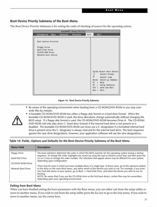
Boot Device Priority Submenu of the Boot Menu
The Boot Device Priority Submenu is for setting the order of checking of sources for the operating system.
Figure 14. Boot Device Priority Submenu
Exiting from Boot MenuWhen you have finished setting the boot parameters with the Boot menu, you can either exit from the setup utility or move to another menu. If you wish to exit from the setup utility press the Esc key to go to the Exit menu. If you wish to move to another menu, use the cursor keys.
■ Be aware of the operating environment when booting from a CD-ROM/DVD-ROM or you may over-write files by mistake.
■ A bootable CD-ROM/DVD-ROM has either a floppy disk format or a hard drive format. When the bootable CD-ROM/DVD-ROM is used, the drive allocations change automatically without changing the BIOS setup. If a floppy disk format is used, the CD-ROM/DVD-ROM becomes Drive A. The CD-ROM/DVD-ROM will only take drive C: (hard drive format) if the internal hard drive is not present or is disabled. The bootable CD-ROM/DVD-ROM can never use a C: designation if a formatted internal hard drive is present since the C: designator is always reserved for the internal hard drive. The boot sequence ignores the new drive designations, however, your application software will use the new designations..
Table 14: Fields, Options and Defaults for the Boot Device Priority Submenu of the Boot Menu
Menu Field Description
Floppy Drive
Hard Disk Drive
CD/DVD-ROM Drive
Network Boot Drive
The boot selections determine the order in which the BIOS searches for the operating system during a startup sequence. To change the order, highlight one source by using the [up] or [down] cursor keys and then press the [+] or [-] key to change the order number. The selections that appear above may be different for your system, depending upon configuration.
There may be cases in which you have multiple drives of a single type. In those cases, go to the submenu related to the drive on the main Boot menu, and select which of the devices you wish to use. For example, if you have two hard disk drives in your system, go to Boot -> Hard Disk Drive, and select the device you wish to use for booting. NOTE: Be aware that if you use the CD-ROM drive as the first boot device, certain files may be overwritten, depending upon your operating environment.
InsydeH20 Setup Utility
Information Main Advanced Security Boot Exit
▲
Up/Dn Select Boot Device<> Select Screen
Select ItemEnter Select SubmenuF1 = HelpF9 = Setup DefaultsF10 = Save and ExitEsc = Exit
Boot Device Priority
Floppy DriveHard Disk DriveCD/DVD-ROM DriveNetwork Boot Device
L i f e B o o k N S e r i e s N o t e b o o k B I O S
22
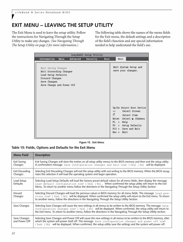
EXIT MENU – LEAVING THE SETUP UTILITYThe Exit Menu is used to leave the setup utility. Follow the instructions for Navigating Through the Setup Utility to make any changes. (See Navigating Through The Setup Utility on page 2 for more information.)
The following table shows the names of the menu fields for the Exit menu, the default settings and a description of the field's function and any special information needed to help understand the field's use.
Figure 15. Exit Menu
Table 15: Fields, Options and Defaults for the Exit Menu
Menu Field Description
Exit Saving Changes
Exit Saving Changes will store the entries on all setup utility menus to the BIOS memory and then exit the setup utility. A confirmation message Save Configuration changes and exit now? [Yes] [No] will be displayed.
Exit Discarding Changes
Selecting Exit Discarding Changes will exit the setup utility with out writing to the BIOS memory. When the BIOS recog-nizes this selection it will load the operating system and begin operation.
Load Setup Defaults
Selecting Load Setup Defaults will load the factory preset default values for all menu fields, then display the message Load default configuration now? [Yes] [No]. When confirmed the setup utility will return to the Exit Menu. To return to another menu follow the directions in the Navigating Through the Setup Utility Section.
Discard Changes
Selecting Discard Changes will load the previous values in BIOS memory for all menu fields. The message Load pre-vious now? [Yes] [No] will be displayed. When confirmed the setup utility will return to the Exit menu. To return to another menu, follow the directions in the Navigating Through the Setup Utility Section.
Save Changes Selecting Save Changes will cause the new settings in all menus to be written to the BIOS memory. The message Save configuration changes now? [Yes] [No] will be displayed. When confirmed, the setup utility will return to the Exit menu. To return to another menu, follow the directions in the Navigating Through the Setup Utility section.
Save Changes and Power Off
Selecting Save Changes and Power Off will cause the new settings in all menus to be written to the BIOS memory, after which the system will power itself off. The message Save configuration changes and power off now? [Yes] [No] will be displayed. When confirmed, the setup utility save the settings and the system will power off.
InsydeH20 Setup Utility
Information Main Advanced Security Boot Exit
▲
Up/Dn Select Boot Device<> Select Screen
Select ItemEnter Select SubmenuF1 = HelpF9 = Setup DefaultsF10 = Save and ExitEsc = Exit
Exit System Setup andsave your changes.
Exit Saving ChangesExit Discarding ChangesLoad Setup DefaultsDiscard ChangesSave ChangesSave Change and Power Off


![BIOS SECTION S2110 - Fujitsu Global · BIOS SECTION S2110. 2 ... in your BIOS memory, ... Primary Master [TOSHIBA MK4025GAS-(PM)] Secondary Master [MATSHITADVD-RAM UJ-840S- ...](https://static.fdocuments.in/doc/165x107/5b0dd4817f8b9a02508e5efb/bios-section-s2110-fujitsu-section-s2110-2-in-your-bios-memory-primary.jpg)
![BIOS SECTION P7230 - Fujitsu · BIOS SECTION P7230. 2 LifeBook P7000 Notebook BIOS ... Press [F2] once the Fujitsu logo appears on the screen. This will open the main menu of the](https://static.fdocuments.in/doc/165x107/5b5c46157f8b9a65028b805c/bios-section-p7230-bios-section-p7230-2-lifebook-p7000-notebook-bios-.jpg)