Biometric Fingerprint - IJESIijesi.org/papers/Vol 2(7)/Version-3/F0273031049.pdf · Fingerprint...
19
International Journal of Engineering Science Invention ISSN (Online): 2319 – 6734, ISSN (Print): 2319 – 6726 www.ijesi.org Volume 2 Issue 7 ǁ July. 2013 ǁ PP.31-49 www.ijesi.org 31 | Page “Biometric Fingerprint” 1, Aman Chandra Kaushik , 2, Abheek Chaudhuri , 3, Vandana Sharma, 4, Paroma Bhattacharya 1,2,3,4, Department of Bioinformatics, University Institute of Engineering & Technology Chhatrapati Shahu Ji Maharaj University, Kanpur-208024, Uttar Pradesh, India ABSTRACT: Fingerprint-based identification is one of the most important biometric technologies which have drawn a Substantial amount of attention. Humans have used fingerprints for personal identification for centuries and the validity of fingerprint identification has been well established. In fact, fingerprint technology is so common in personal identification that it has almost become the synonym of biometrics. Fingerprints are believed to be unique across individuals and across fingers of same individual. Even identical twins having similar DNA, are believed to have different fingerprints. These observations have led to the increased use of automatic finger print based identification in both civilian and law-enforcement applications. I. INTRODUCTION: A fingerprint is the pattern of ridges and furrows on the surface of a fingertip. Ridges and valleys are often run in parallel and sometimes they bifurcate and sometimes they terminate. When fingerprint image is analyzed at global level, the fingerprint pattern exhibits one or more regions where ridge lines assume distinctive shapes. These shapes are characterized by high curvature, terminations, bifurcations, cross-over etc. These regions are called singular regions or singularities. These singularities may be classified into three topologies; loop, delta and whorl. At local level, there are other important features known as minutiae can be found in the fingerprint patterns. Minutiae mean small details and this refers to the various ways that the ridges can be discontinuous. A ridge can suddenly come to an end which is called termination or it can divide into two ridges which is called bifurcation. Fingerprint matching techniques can be broadly classified as minutiae based and correlation based. Minutiae based technique first locates the minutiae points in a given fingerprint image and matches their relative placements in a stored template fingerprint. A good quality fingerprint contains between 60 and 80 minutiae, but different fingerprints have different number of minutiae. The performance of minutiae-based techniques rely on the accurate detection of minutiae points and the use of sophisticated matching techniques to compare two minutiae fields which undergo non-rigid transformations. Correlation based techniques compare the global pattern of ridges and valleys to see if the ridges in the two fingerprints align Figure1: Finger rint Pattern
Transcript of Biometric Fingerprint - IJESIijesi.org/papers/Vol 2(7)/Version-3/F0273031049.pdf · Fingerprint...

International Journal of Engineering Science Invention
ISSN (Online): 2319 – 6734, ISSN (Print): 2319 – 6726
www.ijesi.org Volume 2 Issue 7 ǁ July. 2013 ǁ PP.31-49
www.ijesi.org 31 | Page
“Biometric Fingerprint”
1,Aman Chandra Kaushik ,
2,Abheek Chaudhuri ,
3,Vandana Sharma,
4,Paroma
Bhattacharya 1,2,3,4,Department of Bioinformatics, University Institute of Engineering & Technology
Chhatrapati Shahu Ji Maharaj University, Kanpur-208024, Uttar Pradesh, India
ABSTRACT: Fingerprint-based identification is one of the most important biometric technologies which have
drawn a Substantial amount of attention. Humans have used fingerprints for personal identification for centuries and the validity of fingerprint identification has been well established. In fact, fingerprint technology
is so common in personal identification that it has almost become the synonym of biometrics. Fingerprints are
believed to be unique across individuals and across fingers of same individual. Even identical twins having
similar DNA, are believed to have different fingerprints. These observations have led to the increased use of
automatic finger print based identification in both civilian and law-enforcement applications.
I. INTRODUCTION: A fingerprint is the pattern of ridges and furrows on the surface of a fingertip. Ridges and valleys are
often run in parallel and sometimes they bifurcate and sometimes they terminate. When fingerprint image is
analyzed at global level, the fingerprint pattern exhibits one or more regions where ridge lines assume
distinctive shapes. These shapes are characterized by high curvature, terminations, bifurcations, cross-over etc.
These regions are called singular regions or singularities. These singularities may be classified into three
topologies; loop, delta and whorl. At local level, there are other important features known as minutiae can be
found in the fingerprint patterns. Minutiae mean small details and this refers to the various ways that the ridges
can be discontinuous. A ridge can suddenly come to an end which is called termination or it can divide into two
ridges which is called bifurcation.
Fingerprint matching techniques can be broadly classified as minutiae based and correlation based. Minutiae based technique first locates the minutiae points in a given fingerprint image and matches their relative
placements in a stored template fingerprint. A good quality fingerprint contains between 60 and 80 minutiae, but
different fingerprints have different number of minutiae. The performance of minutiae-based techniques rely on
the accurate detection of minutiae points and the use of sophisticated matching techniques to compare two
minutiae fields which undergo non-rigid transformations. Correlation based techniques compare the global
pattern of ridges and valleys to see if the ridges in the two fingerprints align
Figure1: Finger rint Pattern

Biometric Fingerprint
www.ijesi.org 32 | Page
Figure1.1: Minutia (Valley is also referred as Furrow, Termination is also called Ending, and Bifurcation is also
called Branch).
Flow diagram of fingerprint recognition algorithm.
The fingerprint recognition problem can be grouped into two sub-domains: one is fingerprint verification and
the other is fingerprint identification (Figure 1.2.). In addition, different from the manual approach for
fingerprint recognition by experts, the fingerprint recognition here is referred as AFRS (Automatic Fingerprint Recognition System), which is program-based.

Biometric Fingerprint
www.ijesi.org 33 | Page
Figure 1.2: Verification vs. Identification
Fingerprint verification is to verify the authenticity of one person by his fingerprint. The user provides
his fingerprint together with his identity information like his ID number. The fingerprint verification system
retrieves the fingerprint template according to the ID number and matches the template with the real-time
acquired fingerprint from the user. Usually it is the underlying design principle of AFAS (Automatic Fingerprint
Authentication System).Fingerprint identification is to specify one person‟s identity by his fingerprint(s).
Without knowledge of the person‟s identity, the fingerprint identification system tries to match his fingerprint(s)
with those in the whole fingerprint database. It is especially useful for criminal investigation cases. And it is the
design principle of AFIS (Automatic Fingerprint Identification System).
II. IMAGE ENCHANCEMENT
When an image is scanned from a finger print scanner the center of image and its support are quite
clear and easy to study. There is another part of image that is much darker and its size and other feature are not
easily discernable . In this the problem to enchance dark areas while leaving the other area as unchanged as
possible since it does not require enchancement.the objective of enhancement
is to improve the interpretability of the information present in images for human viewers.
Figure3: Input Fringer Print
Biometric Fingerprint
www.ijesi.org 34 | Page
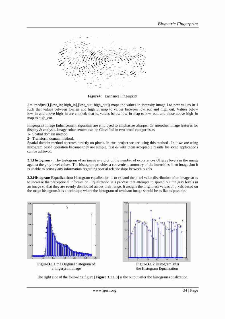
Figure4: Enchance Fingerprint
J = imadjust(I,[low_in; high_in],[low_out; high_out]) maps the values in intensity image I to new values in J
such that values between low_in and high_in map to values between low_out and high_out. Values below low_in and above high_in are clipped; that is, values below low_in map to low_out, and those above high_in
map to high_out.
Fingerprint Image Enhancement algorithm are employed to emphasize ,sharpen Or smoothen image features for
display & analysis. Image enhancement can be Classified in two broad categories as
1- Spatial domain method.
2- Transform domain method. Spatial domain method operates directly on pixels. In our project we are using this method . In it we are using
histogram based operation because they are simple, fast & with them acceptable results for some applications
can be achieved.
2.1.Histogram -: The histogram of an image is a plot of the number of occurrences Of gray levels in the image
against the gray-level values. The histogram provides a convenient summary of the intensities in an image ,but it
is unable to convey any information regarding spatial relationships between pixels.
2.2.Histogram Equalization: Histogram equalization is to expand the pixel value distribution of an image so as
to increase the perceptional information. Equalization is a process that attempts to spread out the gray levels in
an image so that they are evenly distributed across their range. It assigns the brightness values of pixels based on the mage histogram.It is a technique where the histogram of resultant image should be as flat as possible.
Figure3.1.1 the Original histogram of
a fingerprint image
Figure3.1.2 Histogram after
the Histogram Equalization
The right side of the following figure [Figure 3.1.1.3] is the output after the histogram equalization.

Biometric Fingerprint
www.ijesi.org 35 | Page
Figure3.1.3 Histogram Enhancement. Original Image (Left). Enhanced image (Right)
2.3.Fingerprint Image Binarization
Fingerprint Image Binarization is to transform the 8-bit Gray fingerprint image to a 1-bit image with 0-
value for ridges and 1-value for furrows. After the operation, ridges in the fingerprint are highlighted with black
color while furrows are white.
A locally adaptive binarization method is performed to binarize the fingerprint image. Such a named
method comes from the mechanism of transforming a pixel value to 1 if the value is larger than the mean
intensity value of the current block (16x16) to which the pixel belongs [Figure 3.2.1].
Figure3.2.1 the Fingerprint image after adaptive binarization Binarized image (left), Enhanced gray image (right)
2.4.Segmentation The first step of the fingerprint enhancement algorithm is image segmentation.Segmentation is the
process of separating the foreground regions in the image from the background regions. The foreground regions
correspond to the clear fingerprint area containing the ridges and valleys, which is the area of interest. The
background corresponds to the regions outside the borders of the fingerprint area, which do not
contain any valid fingerprint information. When minutiae extraction algorithms are applied to the background
regions of an image, it results in the extraction of noisy and false minutiae. Thus, segmentations employed to
discard these background regions, which facilitate the reliable extraction of minutiae.
In general, only a Region of Interest (ROI) is useful to be recognized for each fingerprint image. The image area
without effective ridges and furrows is first discarded since it only holds background information. Then the bound of the remaining effective area is sketched out since the minutia in the bound region is confusing with
that spurious minutia that are generated when the ridges are out of the sensor.
To extract the ROI, a two-step method is used. The first step is block direction estimation and direction variety
check [1], while the second is intrigued from some Morphological methods.

Biometric Fingerprint
www.ijesi.org 36 | Page
2.4.Block direction estimation Estimate the block direction for each block of the fingerprint image with WxW in size(W is 16 pixels by
default). The algorithm is:
[1] Calculate the gradient values along x-direction (gx) and y-direction (gy) for each pixel of the block. Two
Sobel filters are used to fulfill the task.
[2] For each block, use Following formula to get the Least Square approximation of the block direction.
[3] tg2ß = 2 (gx*gy)/ (gx2-gy2) for all the pixels in each block.
[4] The formula is easy to understand by regarding gradient values along x-direction and y-direction as
cosine value and sine value. So the tangent value of the block direction is estimated nearly the same as
the way illustrated by the following formula.
[5] tg2 = 2sin cos /(cos2 -sin2 ) [6] 1.2 After finished with the estimation of each block direction, those blocks without significant
information on ridges and furrows are discarded based on the following formulas:
E = {2 (gx*gy)+ (gx2-gy2)}/ W*W* (gx2+gy2)
For each block, if its certainty level E is below a threshold, then the block is regarded as a background block.
The direction map is shown in the following diagram. We assume there is only one fingerprint in each image.
Figure3.3.1.1 Direction map Binarized fingerprint (left), Direction map (right)
2.5.ROI extraction by Morphological operations
Two Morphological operations called „OPEN‟ and „CLOSE‟ are adopted. The „OPEN‟ operation can
expand images and remove peaks introduced by background noise [Figure 3.3.2.2]. The „CLOSE‟ operation can shrink images and eliminate small cavities [Figure 3.3.2.3].
Figure 3.3.2.1 Original Image Area Figure 3.3.2.2 After CLOSE operation
Figure 3.3.2.3 After OPEN operation Figure 3.3.2.4 ROI + Bound

Biometric Fingerprint
www.ijesi.org 37 | Page
Figure 3.3.2.4 show the interest fingerprint image area and its bound. The bound is the subtraction of the closed
area from the opened area. Then the algorithm throws away those leftmost, rightmost, uppermost and
bottommost blocks out of the bound so as to get the tightly bounded region just containing the bound and inner
area.
SELECTED QUERY FINGERPRINT
SEGMENTED QUERY FINGERPRINT
Figure5: Selected and Segmented Query Finger Print
2.6.Gabor Filter
Gabor filter method is assumed that the parallel ridges and valleys exhibit some ideal sinusoidal-shaped plane waves associated with some noises. In other words, the 1-Dsignal orthogonal to the local orientation is
approximately a digital sinusoidal wave.
Figure6: Ridges and Valleys Pattern
Fingerprint images present a strong orientation tendency and have a well-defined spatial frequency in
each local neighborhood that does not contain singular point(s) Gabor filters are band-pass filters which have
both orientation-selective and frequency-selective properties and have optimal joint resolution in both spatial
and frequency domains. By applying properly tuned Gabor filters to a fingerprint image, the true ridge and
furrow structures can be greatly accentuated. These accentuated ridges and furrow structures constitute an

Biometric Fingerprint
www.ijesi.org 38 | Page
efficient representation of a fingerprint image.An even symmetric Gabor filter has the following general form in
the spatial domain:
where f is the frequency of the sinusoidal plane wave along the direction q from the x-axis, and dx and dy
specify the Gaussian envelope along x and y axes, respectively, which determine the bandwidth of the Gabor
filter In our algorithm, the filter frequency f is set to the average ridge frequency (1/K), where K is the inter ridge
distance. The average inter ridge image. If f is too large, spurious ridges may be created in the filtered image,
whereas if f is too small, nearby ridges may be merged into one. The bandwidth of the Gabor filters is
determined by dx and dy. The selection of the values of dx and dy is based on the following trade-off. If they are
too large, the filter is more robust to noise, but is more likely to smooth the image to the extent that the ridge and
furrow details in the fingerprint are lost. On the other hand, if they are too small, the filter is not effective in
removing noise. In our algorithm, the values of dx and dy were empirically determined and both were set to 4.0. If we decompose formula into two orthogonal parts, one parallel and the other perpendicular to the orientation /,
the following formula can be
The first part hx behaves as a 1-D Gabor function which is a band pass filter, and the second one hy
represents a Gaussian function which is a low pass filter Therefore, a 2-D even-symmetric Gabor filter(TGF)
performs a low pass filtering along the orientation / and a band pass filtering orthogonal to its orientation /. The
band pass and low pass properties along the two orthogonal orientations are very beneficial to enhancing
fingerprint images, since these images usually show a periodic alternation between ridges and valleys
orthogonal to the local orientation and parallel exhibit an approximate continuity along the local orientation.It
should be pointed out that hx in formula could be treated as a non-admissible mother wavelet (indicated by its
Fourier representation Its band pass property is related with the rx. If rx is too small, the band pass filter
degenerates into a low pass function. On the other hand, if rx is appropriately large, hx can be approximately
regarded as an admissible mother wavelet with good band pass property.The filter frequency f is set to the
average ridge frequency (1/K), where K is the inter ridge distance. The average inter ridge distance is approximately 10 pixels in a 500 dpi fingerprint image. If f is too large, spurious ridges may be created in the
filtered image, whereas if f is too small, nearby ridges may be merged into one. The rx is the standard deviation
of the 2-D Gaussian function along the x-axis and ry along the y-axis. rx and ry control the spatial– frequency
bandwidth of the response. The larger they are, the wider bandwidth is expected. However, too wide bandwidth
can unexpectedly enlarge the noises, and too narrow bandwidth tends to suppress some useful signals. The value
of ry determines the smoothing degree along the local orientation. Too large ry can blur the minutiae. In our
algorithms, ry is empirically set as 4.0.

Biometric Fingerprint
www.ijesi.org 39 | Page
Figure7: Gabor Filter Function
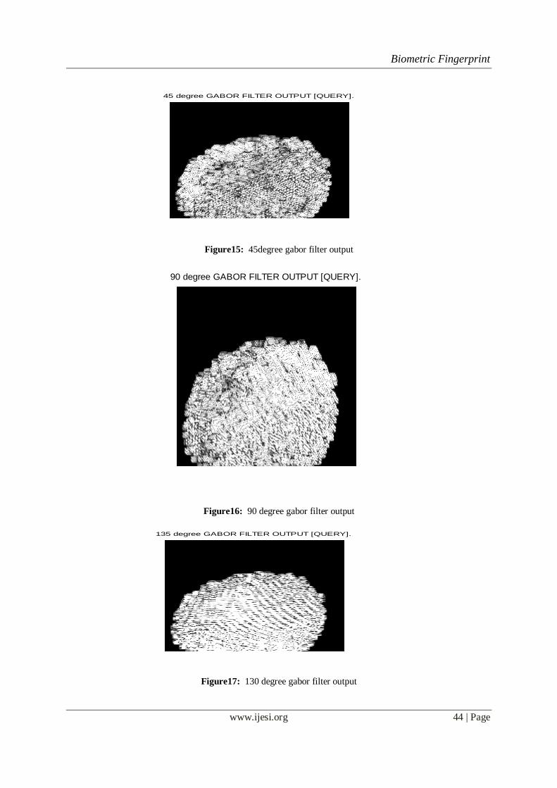
A fingerprint image is decomposed into four component images corresponding to four different values
of q (0o, 45o, 90o, and 135o) with respect to the x-axis. A fingerprint image is convolved with each of the four
Gabor filters to produce the four component images. Convolution with a 0o-oriented filter accentuates ridges parallel to the x-axis, and it smoothes ridges which are not parallel to the x-axis. Filters tuned to other
directions work in a similar way. The four component images capture most of the ridge directionality
information present in a fingerprint image by reconstructing a fingerprint image by adding together all the four
filtered images. The reconstructed image is similar to the original image but the ridge has been enhanced before
decomposing the fingerprint image, we normalize the region of interest in each sector separately to a constant
mean and variance. Normalization is done to remove the effects of sensor noise and finger pressure differences.
Let I(x, y) denote the gray value at pixel (x, y), Mi and Vi, the estimated mean and variance of sector Si,
respectively, and Ni(x, y), the normalized gray-level value at pixel (x, y). For all the pixels in sector Si, the
normalized image is defined as:
Where M0 and V0 are the desired mean and variance values, respectively. Normalization is a pixel-wise
operation which does not change the clarity of the ridge and furrow structures.

Biometric Fingerprint
www.ijesi.org 40 | Page
If normalization is done on the entire image, then it cannot compensate for the intensity variations in the
different parts of the finger due to finger pressure differences. Normalization of each sector separately alleviates
this problem. Ridgeshave been enhanced ridge and valley structures.
Figure8: Gabor Filter Output
III. TESSELLATION A fingerprint consists of a series of ridges that mainly flow parallel to the locally dominant direction
and occasionally make local singularities, like a core or delta point. Since fingerprint patterns have strong
directionality, directional information can be exploited as fingerprint features. In this sense, a DFB is suitable
for extracting the features of fingerprints containing many linear and directional components because it can
effectively and accurately decompose an image into several directional sub band outputs. For feature extraction,
the original fingerprint image is decomposed into directional sub band outputs using the DFB, and the
directional energy of each block can be obtained from the decomposed sub band outputs. Let denote the coefficient at position of sub band corresponding to an image block. The energy of the image
block associated with sub band is defined as

Biometric Fingerprint
www.ijesi.org 41 | Page
Where Each energy value is calculated from the sub band corresponding to the image block. The directional energy distributions of the sample fingerprint image blocks. We can see that by this
directional filtering operation the ridges and valleys became more distinct and noisy components were
suppressed at the same time.
Figure9: Tessellation
IV. FEATURE Extraction
In each component image, a local neighborhood with ridges and furrows that are parallel to the
corresponding filter direction exhibits a higher variation, whereas a local neighborhood with ridges and furrows
that are not parallel to the corresponding filter tends to be diminished by the filter which results in a lower
variation. The spatial distribution of the variations in local neighborhoods of theComponent images thus
constitute a characterization of the global ridge structures and are well captured by the standard deviation of
grayscale values. The standard deviation within the sectors defines the feature vector.
Let Ci (x, y) be the component image corresponding to for sector Si
Feature is the standard deviation Fi defined as
Where Ki is the number of pixels in Si and Miq is the mean of the pixel values in Ciq(x, y). The dimensional
feature vectors, also called Finger Codes

Biometric Fingerprint
www.ijesi.org 42 | Page
V. FINGERPRINT ALIGNMENT AND MATCHING Before the input print and template print are compared with each other, they should be translation ally
and rotationally aligned with each other. In the proposed method, the translational alignment is accomplished by
the reference point detection procedure for the ROI extraction processes. Rotational alignment is achieved by
generating cyclical input feature vectors and matching input feature vectors with template feature vectors. Since the proposed feature extraction process is performed on a block-by-block basis and the directions of ridges
change smoothly, the proposed method is robust to small angular deviations, even without rotation
compensation. However if the input image is significantly rotated, the performance Degrades compensation for
rotation is partially achieved by cyclically rotating the feature values in the feature vector and finding the
minimum distance between the input and template feature vector. This only provides robustness for a small
perturbation with in, that is , half the angle of a sector. However, for this method to be invariant to smaller
perturbations , the extent of the rotation needs to be the same as the multiple of the angle of a sector, e.g., 22.5,
45 or many feature vectors for a variously rotated image must be enrolled in the database. To compensate
effectively for various kinds of rotation, the proposed method converts the ROI from Cartesian to polar
coordinates. In Cartesian coordinates, the rotation of an image changes the entire directional sub bands to totally
different ones, whereas in polar coordinates rotation corresponds to a horizontal shift in each directional sub
band output. Thus the coordinate system conversion facilitates the procedure of compensating for rotation. Instead of using a single feature vector asthe input, the proposed method performs matching using several
feature vectors in which various rotations are considered. After an input fingerprint image is decomposed into
eight directional sub band outputs, the input feature vectors are obtained by cyclically shifting the sub band
images
Figure10: Feature vector
Fingerprint matching is performed based on finding the normalized Euclidean distance between the
input feature vectors and the template feature vector enrolled in the database. Let denote the -direction feature value for the th block of the ROI for an input fingerprint image, in which degree rotation is considered and let
denote the -direction feature value for the th block of the ROI for the template fingerprint.
Then the normalized Euclidean distance between input and template image
and is the number of the feature vector elements where is not zero. Rotational and translational alignment
between the input and template fingerprints is achieved by finding the minimum normalized Euclidean distance
between the input and template feature vectors.

Biometric Fingerprint
www.ijesi.org 43 | Page
VI. SIMULATION RESULT
SELECTED QUERY FINGERPRINT
Figure11: Input Image
SEGMENTED QUERY FINGERPRINT
Figure12: Segmented query fingerprint
ENHANCED QUERY FINGERPRINT
Figure13: Enhanced Image
0 degree GABOR FILTER OUTPUT [QUERY].
Figure14: 0 degree gabor filter output
Biometric Fingerprint
www.ijesi.org 44 | Page
45 degree GABOR FILTER OUTPUT [QUERY].
Figure15: 45degree gabor filter output
90 degree GABOR FILTER OUTPUT [QUERY].
Figure16: 90 degree gabor filter output
135 degree GABOR FILTER OUTPUT [QUERY].
Figure17: 130 degree gabor filter output

Biometric Fingerprint
www.ijesi.org 45 | Page
User Manual
1. Type command start_gui_single_mode in MATLAB 6.0
Figure M.1 the User Interface of the Fingerprint Recognition System. The series of buttons on the left side will
be invoked sequentially in the consequent demonstration. The two blank areas are used to show the fingerprint
image before and after a transaction respectively.

Biometric Fingerprint
www.ijesi.org 46 | Page
2. Click Load Button
Figure M.2 Load a gray level fingerprint image from a drive specified by Users. Multiple formats are supported
and the image size is not limited. But the fingerprint ridges should have large gray intensity comparing with the
background and valleys.
3. Click his-Equalization Button
Figure M.3 After Histogram Equalization. The image on the left side is the original fingerprint. The enhanced
image after the Histogram Equalization is shown on the right side.
4. Click fft Button
Figure M.4 Captured window after click „FFT‟ button. The pop-up dialog accepts the parameter k (please refer
the formula 2). The experimental optimal k value is 0.45. Users can fill any other constant in the dialog to get a
better performance. The enhanced image will be shown in the left screen box, which however is not shown here.
Its replaced by gabour

Biometric Fingerprint
www.ijesi.org 47 | Page
5. Click Binarization Button
Figure M.5.6 Screen capture after binarization (left) and block direction estimation (right).
7. Click ROI Area Button
Figure M.7 ROI extraction(right). The intermediate steps for all the morphological operations such close and
open are not shown. The right screen box shows the final region of interest of the fingerprint image. The subsequent operations will only operate on the region of interest.
8. Click Thinning Button
9. Click Remove H breaks Button
10. Click Remove spikes Button
Figure M.10 the Fingerprint image after thining, H breaks removal, isolated peaks removal and spike removal.(right).

Biometric Fingerprint
www.ijesi.org 48 | Page
11. Click Extract Button
Click Real Minutia Button
Figure M.12 Minutia marking (right) and False Minutia Removal (Left). Bifurcations are located with yellow
crosses and terminations are denotes with red stars. And the genuine minutia (left) is labeled with orientations
with green arrows.
12. Click Save Button
Figure M.13 Save minutia to a text file. The saved text file stores the information on all genuine minutia. The
exact format of the files are explained in the source code.
13. Click Match Button
Figure M.14 Load two minutia files and do matching. Users can open two minutia data files from the dialog
invoked by clicking the „Match‟ button. The match algorithm will return a prompt of the match score. But be

Biometric Fingerprint
www.ijesi.org 49 | Page
noted that matching in the GUI mode is not encouraged since the match algorithm relies on heavy computation.
Unpredicted states will happen after a long irresponsive running time. Batch testing is prepared for testing
match. Please refer the source files for batch testing.
REFERENCES [1] A. K. Jain, L. Hong, S. Pankanti, and R. Bolle, “An identity authentication
system using fingerprints,” Proc. IEEE, vol. 85, pp. 1365–1388, Sept. 1997.
[2] R. H. Bamberger and M. J. T. Smith, “A filter bank for the directional
decomposition of images: Theory and design,” IEEE Trans. Signal
Processing, vol. 40, pp. 882–893, Apr. 1992.
[3] Almansa, A., Lindeberg, T., 2000. Fingerprint enhancement by shape adaptation of scale-space operators with automatic scale
selection. IEEE Trans. Image Process.
[4] L. Hong, Y. Wan, and A.J. Jain, “Fingerprint Image Enhancement: Algorithm and Performance Evaluation,” IEEE Transactions
on Pattern Analysis and Machine Intelligence, vol. 20,no. 8, pp.777-789, August 1998.
[5] V. Areekul, U. Watchareeruetai, and S. Tantaratana, “Fast Separable Gabor Filter for Fingerprint Enhancement,” Proceeding
International Conference on Biometric Authentication (ICBA2004), LNCS3072, Springer, pp. 403-409, 2004
[6] A. Ross, A. K. Jain, and J. Reisman, "A Hybrid Fingerprint Matcher", Pattern Recognition, Vol. 36, No. 7, pp. 1661-1673, 2003.