Biomet Multi-Axial Correction (MAC) System · mechanical axis of the limb through a system of...
40
Surgical Technique Biomet Multi-Axial Correction (MAC) System
Transcript of Biomet Multi-Axial Correction (MAC) System · mechanical axis of the limb through a system of...

Surgical Technique
Biomet Multi-Axial Correction (MAC) System

Contents
Introduction .................................................. Page 1
Indications and Contraindications ................. Page 2
Device Description ........................................ Page 6
Technique Overview ..................................... Page 8
Surgical Technique ....................................... Page 10
CORA-Centric ............................................ Page 10
CORA-Perpendicular ................................. Page 14
CORA-Proximal ......................................... Page 18
Rotation Ring Application .......................... Page 19
Using The Angulation Rate Turn Guide .......... Page 20
Applications .................................................. Page 25
Case Examples ............................................ Page 26 Ollier’s Disease ........................................ Page 26 Charcot Foot Collapse .............................. Page 28 Multi-planar Femoral Deformity ............... Page 30
Application Examples ................................... Page 31
Additional Biomet Options To Consider ........ Page 33
Further Information ....................................... Page 34

1
Introduction
The Biomet MAC (Multi-Axial Correction) System is an
external fixation system with the unique ability to gradually
or acutely correct single or multi-planar deformities of the
extremities utilizing two planes of angulation and two
planes of translation, rotation and lengthening. The MAC
System is a component system that allows the correcting
mechanism to be applied directly at the point of deformity to
minimize secondary deformities.
Through compatible rails, rings, and arcs, bone screws can
be applied to the limited safe zones of human anatomy. This
reduces soft tissue injuries and stiffness. In turn, the need
for physical therapy declines. With the MAC System, it is
possible to accomplish all this without compromising
accurate and efficient correction of deformity.
Injury, birth defects, tumors, growth disturbances, and
metabolic diseases can cause deformities of the limbs.
Since the mid 1980’s, complex multi-planar deformities
have been treated using ring fixation systems. Ring fixation
revolutionized the ability of the orthopedic surgeon to
correct such complex deformities. However, these same
ring fixators can be bulky, cumbersome and complicated
to use, for both the treating physician and the patient.
Failure to correctly apply any fixator can lead to residual
or secondary deformities. Such deformities can then be
difficult or impossible to correct with standard fixators.
The MAC System allows for accurate correction of the limb
deformities. It also provides the ability to directly correct
those common secondary deformities, inherent in, and
resulting from corrections with external fixators, by simply
dialing in the multi-planar corrections.

2
Indications and Contraindications
INDICATIONS
The Biomet Multi-Axial Correction (MAC) System is an external
fixation device intended for use in the treatment of bone condi-
tions including leg lengthening, osteotomies, arthrodesis, fracture
fixation, and other bone conditions amenable to treatment by use
of the external fixation modality.
CONTRAINDICATIONS
Patients with mental or neurologic conditions who are unwilling
or incapable of following postoperative care instructions.

3
Adult MAC Tray
Adult Multi-Axial Correction (MAC) Deformity SystemCatalog No. 00048
Catalog # Description Qty.03178 Surgical Tray 1
Top LevelCatalog # Description Qty.09595 3.2 mm Guide Pin 203075 Trocars 203085 60 mm Soft Tissue Guides 403090 80 mm Soft Tissue Guides 203110 5 mm Allen Wrench 203125 T-Wrench for Bone Screws 2-------- (Includes (1) 03216 in above item) 203216 1.6 mm Partially Threaded k-wire 203225 4.8 mm Cannulated Drill Bit 203215 3.2 mm Cannulated Drill Bit 403015 4.8 mm x 240 mm Drill Bit 203035 3.2 mm x 200 mm Drill Bit 203060 4.8 mm Drill Guide 203065 3.2 mm Drill Guide 215305 Low Profile Clamp (Not Shown) 2
Middle LevelCatalog # Description Qty.13080 Variable Bone Screw Carriage 615240 130 mm Rotating Ring 115250 220 mm Rotating Ring 115255 180 mm Rotating Ring 115260 150 mm Rotating Ring 1
Base LevelCatalog # Description Qty.15210 MAC Correction Module 215219 MAC Ring Bolt 415220 Ring-Male Rotation Adapter 215270 MAC-Female Rotation Adapter 401801 Construx Fixator 101810 Male Telescoping Arm Complete 101820 Female Telescoping Arm Complete 101180 1-5 cm C/D Mechanism 201227 Distraction Wrench 215290 MAC-Ring Distraction Mechanism 1

XS Rotating Ring
XS Slotted AC
XS Fixator T-Clamp
XS Ring Bolt
XS Variable Screw Carriage
XS Bone Clamp
XS Rails, Clamps and Bridges
XS MAC Tray
XS MAC Module
XS Fixator Complete
1 Knuckle XS Fixator
2 Knuckle XS Fixator
3 Knuckle XS Fixator
XS Ring - Female Adapter
XS MAC - Female Adapter
XS Ring - Male Adapter
Tray Layouts
4
5
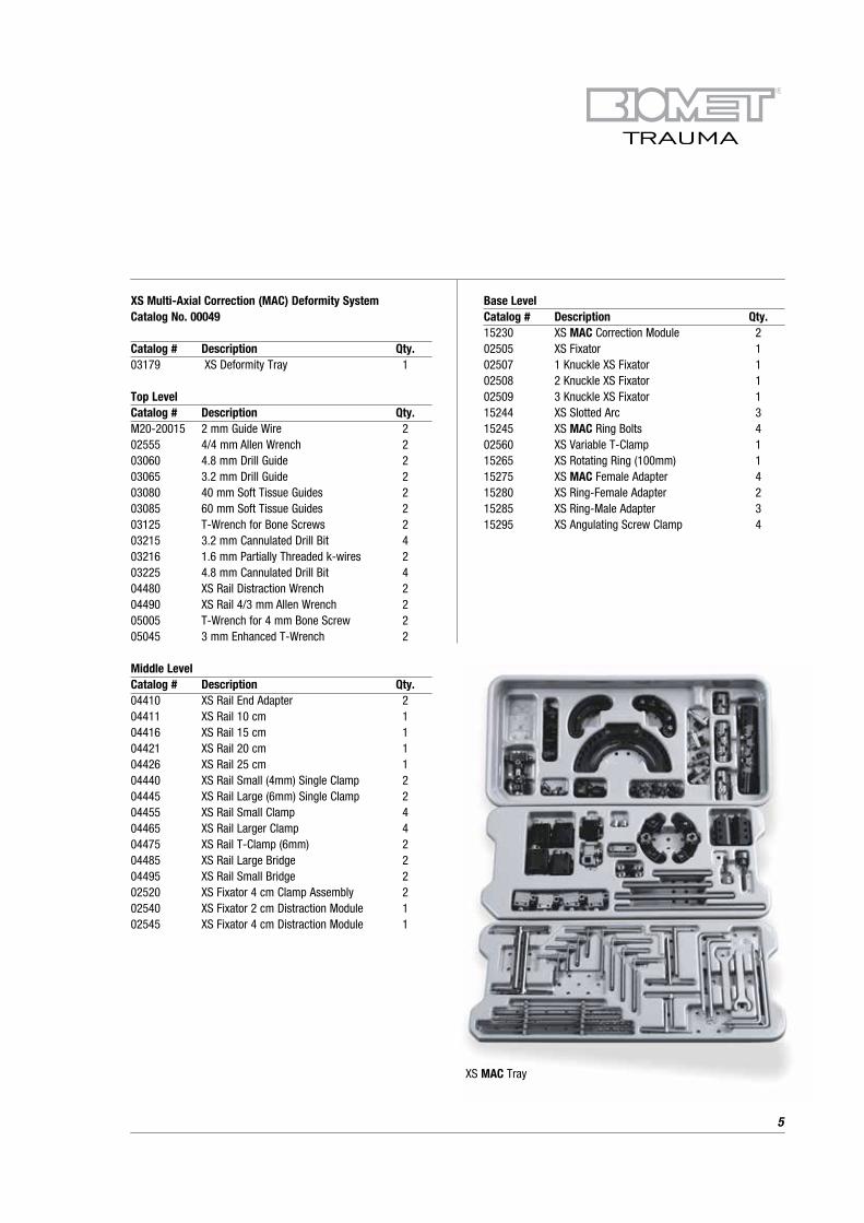
XS MAC Tray
Base LevelCatalog # Description Qty.15230 XS MAC Correction Module 202505 XS Fixator 102507 1 Knuckle XS Fixator 102508 2 Knuckle XS Fixator 102509 3 Knuckle XS Fixator 115244 XS Slotted Arc 315245 XS MAC Ring Bolts 402560 XS Variable T-Clamp 115265 XS Rotating Ring (100mm) 115275 XS MAC Female Adapter 415280 XS Ring-Female Adapter 215285 XS Ring-Male Adapter 315295 XS Angulating Screw Clamp 4
XS Multi-Axial Correction (MAC) Deformity SystemCatalog No. 00049
Catalog # Description Qty.03179 XS Deformity Tray 1
Top LevelCatalog # Description Qty.M20-20015 2 mm Guide Wire 202555 4/4 mm Allen Wrench 203060 4.8 mm Drill Guide 203065 3.2 mm Drill Guide 203080 40 mm Soft Tissue Guides 203085 60 mm Soft Tissue Guides 203125 T-Wrench for Bone Screws 203215 3.2 mm Cannulated Drill Bit 403216 1.6 mm Partially Threaded k-wires 203225 4.8 mm Cannulated Drill Bit 404480 XS Rail Distraction Wrench 204490 XS Rail 4/3 mm Allen Wrench 205005 T-Wrench for 4 mm Bone Screw 205045 3 mm Enhanced T-Wrench 2
Middle LevelCatalog # Description Qty.04410 XS Rail End Adapter 204411 XS Rail 10 cm 104416 XS Rail 15 cm 104421 XS Rail 20 cm 104426 XS Rail 25 cm 104440 XS Rail Small (4mm) Single Clamp 204445 XS Rail Large (6mm) Single Clamp 204455 XS Rail Small Clamp 404465 XS Rail Larger Clamp 404475 XS Rail T-Clamp (6mm) 204485 XS Rail Large Bridge 204495 XS Rail Small Bridge 202520 XS Fixator 4 cm Clamp Assembly 202540 XS Fixator 2 cm Distraction Module 102545 XS Fixator 4 cm Distraction Module 1
Device Description
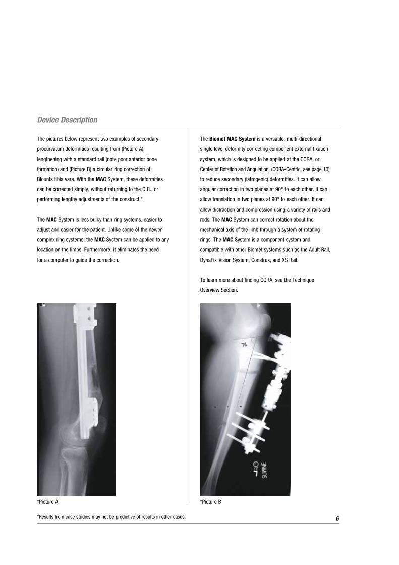
The pictures below represent two examples of secondary
procurvatum deformities resulting from (Picture A)
lengthening with a standard rail (note poor anterior bone
formation) and (Picture B) a circular ring correction of
Blounts tibia vara. With the MAC System, these deformities
can be corrected simply, without returning to the O.R., or
performing lengthy adjustments of the construct.*
The MAC System is less bulky than ring systems, easier to
adjust and easier for the patient. Unlike some of the newer
complex ring systems, the MAC System can be applied to any
location on the limbs. Furthermore, it eliminates the need
for a computer to guide the correction.
The Biomet MAC System is a versatile, multi-directional
single level deformity correcting component external fixation
system, which is designed to be applied at the CORA, or
Center of Rotation and Angulation, (CORA-Centric, see page 10)
to reduce secondary (iatrogenic) deformities. It can allow
angular correction in two planes at 90° to each other. It can
allow translation in two planes at 90° to each other. It can
allow distraction and compression using a variety of rails and
rods. The MAC System can correct rotation about the
mechanical axis of the limb through a system of rotating
rings. The MAC System is a component system and
compatible with other Biomet systems such as the Adult Rail,
DynaFix Vision System, Construx, and XS Rail.
To learn more about finding CORA, see the Technique
Overview Section.
6
*Picture A
*Results from case studies may not be predictive of results in other cases.
*Picture B
The MAC System can also be applied in a plane
perpendicular to the CORA (CORA-Perpendicular).
When placed along the bisector of the CORA, full deformity
correction will occur with varying amounts of lengthening
or shortening, whichever may be desirable. See page 14.
The MAC System can also be placed off the CORA, but
nearby (CORA-Proximal), using the multi-directional
components of the device to correct secondary translation.
See page 17.
Translation errors due to miscalculation and errors of
centering can be corrected after application using the MAC
System’s ability to angulate in two planes, translate in two
planes, lengthen and shorten, as well as rotate the deformity.
Once the CORA is identified, a guide pin is inserted into
the CORA and the MAC System is centered over it and the
screws and wires are safely added on. It is user friendly and
allows for correction of errors (residual deformity) without
returning to the operating room. It allows multi-planar
application of wires or half pins for increased strength.
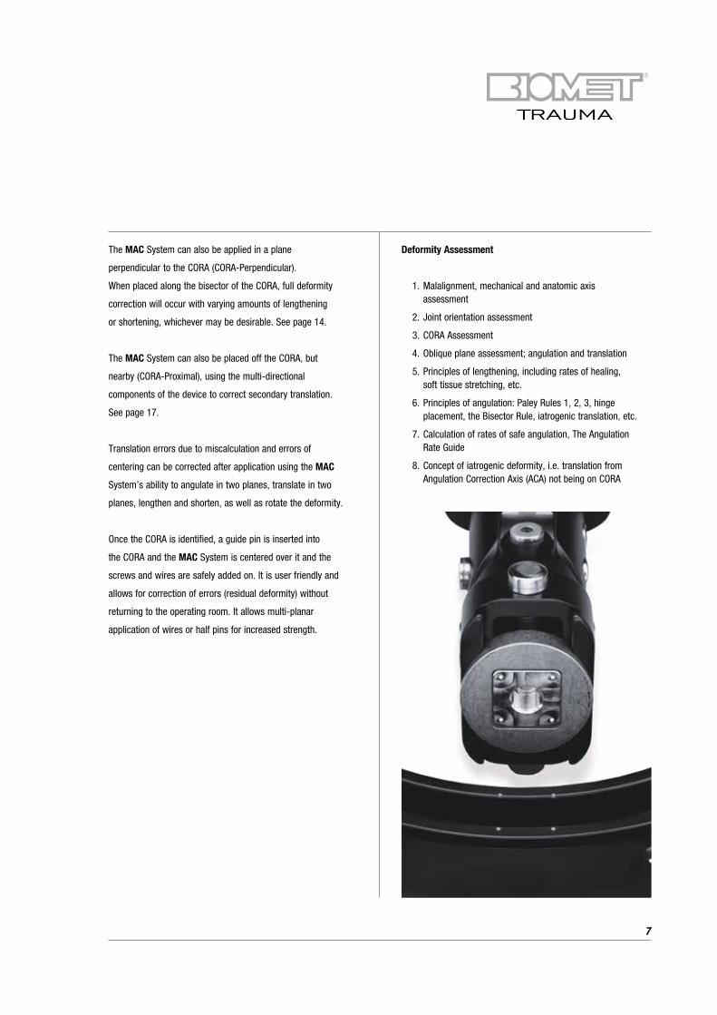
Deformity Assessment
1. Malalignment, mechanical and anatomic axis assessment
2. Joint orientation assessment
3. CORA Assessment
4. Oblique plane assessment; angulation and translation
5. Principles of lengthening, including rates of healing, soft tissue stretching, etc.
6. Principles of angulation: Paley Rules 1, 2, 3, hinge placement, the Bisector Rule, iatrogenic translation, etc.
7. Calculation of rates of safe angulation, The Angulation Rate Guide
8. Concept of iatrogenic deformity, i.e. translation from Angulation Correction Axis (ACA) not being on CORA
7

Technique Overview
Manual Of System Techniques
The Biomet MAC System can be applied in three different locations with respect to the CORA: CORA-Centric, CORA-Perpendicular
and CORA-Proximal. Each permits correction in a unique way.
The CORA-Centric method places the fixator hinge directly over the CORA, minimizing unintended translation.
8
The CORA-Perpendicular application places the fixator hinge on the bisector of the deformity. Placement on the convex side of the
deformity will produce lengthening while placement on the concave side of the deformity will produce shortening. This application
should be employed when such lengthening or shortening is desired .
9
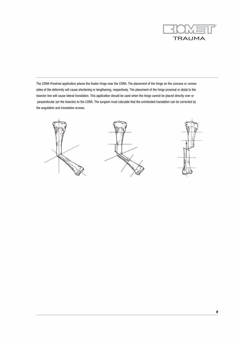
The CORA-Proximal application places the fixator hinge near the CORA. The placement of the hinge on the concave or convex
sides of the deformity will cause shortening or lengthening, respectively. The placement of the hinge proximal or distal to the
bisector line will cause lateral translation. This application should be used when the hinge cannot be placed directly over or
perpendicular (on the bisector) to the CORA. The surgeon must calculate that the unintended translation can be corrected by
the angulation and translation screws.

Surgical Technique
CORA-Centric MAC System Application
NOTE: In this example the Adult MAC System will be used to demonstrate the application.
10
Step 1: Identification of the CORA, see the Technique Overview
NOTE: Allow for at least 1 cm of shortening or lengthening to allow for compression, distraction and clearance of bone edges
during angulation.

Step 2: Place a temporary K-wire (3.2 mm Adult / 1.6 mm XS)
as a guide wire axially through the CORA. If this
would harm neurovascular or other tissues, mark
the skin and hold the device in place manually
on a two-finger breadth spacer.
Step 3: Place a two-finger breadth spacer on the skin over
the guide wire.
Step 4: Place the centering hole of the MAC System
(marked “Primary”) through the guide pin to
rest on the spacer.
NOTE: The primary hinge is capable of 80° and the
secondary hinge is capable of 30°-50°. If the
guide pin is placed perfectly, the deformity
can be fully corrected with the primary hinge.
However, it is difficult to place the pin perfectly
in the CORA, and this will result in a small
iatrogenic angulation, translation, and rotation.
The versatility of the system allows for easy
correction of these secondary deformities.
Step 5: Adjust the hinges so that the arms of the MAC
System are parallel to the CORA divisions of the
deformed bone. The translation screws should be
centered unless a larger translational deformity is to
be corrected, in which case, the translation screws
should be positioned to accomplish that correction.
Step 6: Beginning with the end of the MAC System closest
to a joint, assess the anatomy to determine the
safest and strongest location for bone screw and/or
pin placement. Shorter distances to the bone are
likely to be strongest. Then, select from the
components (simple bone clamp, arcs, rings, rails,
etc.) the component that will connect the MAC to
bone screws. Fix the desired component to the end
of the MAC System. Choose a connection device that
will allow the best fixation and desired lengthening.
Step 7: For the end of the MAC System opposite the closest
joint, assess the anatomy to determine the safest
and strongest location for bone screw and/or pin
placement. Shorter distances are likely to be
strongest. Then select from the components
(simple bone clamp, arcs, rings, rails, etc.) and
fix to the opposing end of the MAC System.
Step 8: With the MAC System in position, begin fixation
(bone screws and/or wires) closest to the nearest
joint. Then place fixation farthest from this point,
making adjustments to assure that all fixation
devices (bone screws and/or wires) will fixate the
bone through diameters of bone. Add additional
fixation as warranted to accomplish correction.
Generally three fixation points (bone screws) on
either side of the osteotomy are recommended.
Step 9: Remove guide pin. The Osteotomy is performed at
the CORA unless there are concerns about the bone
quality or other anatomic problems, such as
ligaments, physes, etc.
Step 10: It is generally best to wait 5-10 days, depending
on age and other factors, before lengthening or
correcting angular deformity.
NOTE: The translation screws move at a rate of
1 mm per 360° turn of the appropriate screw.
The angulation hinges correct at 4° per 360°
turn of the appropriate screw. Angulation
causing lengthening or translation should
proceed at a rate of 1mm/day for nerves at
risk or bone. Faster rates may lead to
permanent nerve damage or delayed and
nonunion. The amount of lengthening for
structures at a specific distance from the
hinge are calculated using the “Angulation
Rate Guide”, (See page 20-24).
11

Surgical Technique (Continued)
CORA-Centric Application, Oblique Plane Tibia Deformity
12

13
CORA-Centric Application, Blounts Proximal Tibia Vara, Rotation Rings
Correcting Rotation

Surgical Technique (Continued)
CORA-Perpendicular MAC System Application
A CORA-Perpendicular construct is primarily recommended
when the MAC System can be safely applied to the convex
side of a deformity where length is desirable. It can also be
used where a lower profile device is desired; however,
calculation of the length change must be made and the device
set up to correct for such length changes.
A simple method to approximate the length change in
CORA-Perpendicular applications:
1. On the X-Ray, at the level of the osteotomy, mark the
position of the fixation device at 2-3 cm from the skin.
2. Draw a line perpendicular from the bone to this point
(distal to the deformity).
3. Take a ruler and place along this line. Pivoting on the point,
rotate the ruler until it is perpendicular to the upper bone
(other side of the deformity). Measure the length change
along the bone.
Step 1: Identification of the CORA, (see Technique Overview).
Identify the bisector line, (see Technique Overview).
Determine the amount of lengthening or shortening
needed. NOTE: the device should be planned for at
least 1 cm of shortening or lengthening to allow for
compression and clearance of bone edges
during angulation.
Step 2: The primary hinge should be aligned along the
bisector, perpendicular to the CORA. Align
the primary hinge at the level of the bisector with
the arms of the MAC System parallel to the upper
and lower limbs of the bone deformity.
14
NOTE: as the MAC System is being applied perpendicular to
the CORA, the axis is not on the CORA and the guide wire
cannot be used.
Step 3: Select from the components (simple bone clamp,
arcs, rings, rails, etc.) and fix to the end of the MAC
System. Choose a connection device that will allow
best fixation and will allow adequate lengthening.
Assemble the device.
Step 4: Place a two-finger breadth spacer on the skin at the
guide wire site.
Step 5: Adjust the hinges so that the arms of the MAC
System are parallel to the limbs of the deformed
bone. There should be at least a two-finger breadth
space between the skin and the device along it’s
entire length.
Step 6: Beginning with the end of the MAC System closest
to a joint, assess the anatomy to determine the
safest and strongest location for bone screw
and/or pin placement. Shorter distances are likely
to be strongest.
Step 7: For the end of the MAC System farthest from the
closest joint assess the anatomy to determine the
safest and strongest location for bone screw and/or
pin placement. Shorter distances are likely to be
strongest. Then select from the components (simple
bone clamp, arcs, rings, rails, etc.) and fix to the end
of the MAC System.

Step 8: With the MAC System in position, begin fixation
(bone screws and/or wires) closest to the nearest
joint. Then place fixation farthest from this point
making adjustments to assure that all fixation
devices (bone screws and/or wires) will fixate
the bone through diameters of bone. Use the
lengtheners, angulation and translation screws
to position the primary hinge along the bisector.
Add additional fixation as warranted to accomplish
correction. Generally three points of fixation above
and below the osteotomy are suggested.
CORA-Perpendicular, Femur Application
15

Surgical Technique (Continued)
16
Check to be sure that there is enough lengthening and
shortening available to obtain the desired length, as well
as compression if needed.
Step 9: The translation portions should be centered unless
translation deformity is to be corrected, in which
case, the translation screws should be positioned
to accomplish that correction.
Step 10: Osteotomy is performed.
Step 11: It is generally best to wait 5-10 days, depending
on age and other factors, before lengthening or
correcting angular deformity.
NOTE: The translation screws move at a rate of 1 mm per
360° turn of the appropriate screw. The angulation hinges
correct at 4° per 360° turn of the appropriate screw.
Angulation causing lengthening or translation should
proceed at a rate of 1mm/day for nerves at risk or bone.
Faster rates may lead to permanent nerve damage or delayed
and nonunion. The amount of lengthening for structures at
a specific distance from the hinge are calculated using the
“Angulation Rate Guide” (See page 20).
*NOTE: In this example of CORA-Perpendicular application,
a second osteotomy was performed to acutely correct
a lesser second deformity at a different level than the
larger deformity. (See steps 1-11 for detailed explanation
of correction).
*Results from case studies may not be predictive of results in other cases.

*Example Of XS MAC System Used On The Forearm In A CORA-Perpendicular Application
17*Results from case studies may not be predictive of results in other cases.

Surgical Technique (Continued)
CORA-Proximal MAC System Application
This application is used when the fixator cannot be
placed at the CORA (CORA-Centric) or along the bisector
(CORA-Perpendicular). The translation, angulation and
rotation screws are needed to correct the secondary
deformities caused by failure to place the device at
the CORA.
18
Below is an example of CORA-Proximal application using the
XS MAC System for proximal tibia vara, Blounts, with a CORA
very close to the joint. Note how the translation device is
used to correct the secondary translation due to not placing
the MAC System directly over the CORA.

Rotation Ring Application
• With proper pre-operative planning up to 90° of rotation can be accomplished with any of the various diameter
rotation rings
• In order to avoid unintended translation when using the MAC System Rotation Arc, it is necessary to center the arc
on the mechanical axis of the limb and keep the plane of the arc perpendicular to the mechanical axis
• Here is a simple method of centering the arc on the mechanical axis using two equal length bone screws
at different angles. The arcs are available in four sizes representing the diameter of the inner edge of the arc. The bone must be centered within the arc. If two bone screws hold the bone at a radius length from the inner edge of the arc, then the bone will be centered. Each bone screw must be the length of the radius of the arc, plus half the diameter of the bone to which it is attached (at the level of attachment), plus the thickness of the rotation arc, plus the width of the bone screw clamp, plus 1 cm beyond the bone screw clamp (to allow for the wrench)
The Formula
Diameter of bone + radius of ring (inner edge of rings) +
thickness of the ring + width of the bone screw clamp +
1 cm for placing the wrench.
• If two screws at two different locations along the arc are screwed along a diameter of the bone into two cortices
and has 1 cm of length beyond the bone screw clamp, then the bone will be centered within the arc
• Any unintended or undesired translation can be corrected using the angulation and translation screws
of the MAC System
19

Using The Angulation Rate Turn Guide
Left/right, varus/valgus, wrench placement one side or
the other, turn clockwise/counterclockwise, etc has always
been a variable in every device designed to gradually correct
deformity. The surgeon must always decide which screw to
turn and in which direction to turn it. Before the Angulation/
Rate/Turn/Guide (ARTG), the surgeon pointed to the screw,
told the patient to place the Allen wrench and “turn in
this direction.”
This has not changed. What has changed is that the patient
will receive a card (ARTG) with instructions that tell him/her
to place the wrench into the screw, turn it in a specific
direction and a specific amount. The doctor will show the
patient where to place the card, in just the same way.
For example: with the MAC System, the doctor might tell the
patient to place the Allen wrench into the primary screw from
the lateral side, place the ARTG facing laterally and line the
filled-in wedge edge with the handle of the wrench. The
doctor will have marked the ARTG with an arrow so the
patient will turn in the direction of the arrow to the other side
of the filled-in wedge.
The reverse side of the ARTG will have the directions, the
frequency of turning (usually 4x/day), and the number of
days to turn.
How to determine the direction of turning is a little harder.
Which arc to turn is easy. The doctor should know where the
deformity is and which arc is in the plane of that deformity.
Choosing the side of the screw to turn should depend on
convenience to the patient or parent who is turning it, that is,
where is it easiest to reach for the person turning. There is
enough play in the device to turn the screw 90° either way,
watching the hinge’s teeth move, without hurting the patient.
20
This allows the doctor to make a trial “double check” in the
office on the day instructions are given to the patient (usually on
the 7-10th day) so he is sure which way he wants the patient to
turn the screw. [The doctor should have done this trial in the
O.R. when he first put the MAC System on.] Instructions are
then given to the patient and written on the ARTG.
The other method to determine which way to turn the screw
is to know that the screw works with the “right hand rule.”
The screw will move along the teeth of the arc. If one points
his right thumb along the axis of the screw, in the direction he
wants the screw to travel, he should turn the screw in the
direction of the fingers of his right hand. Doing this will move
the screw along the teeth of the arc (usually the teeth are
showing out of the MAC). That is the correct direction.
Draw right hand with thumb pointing to part of arc that is
visible (shiny) i.e., to the left. Fingers of the hand tell which
way to turn. The only thing that the ARTG has added is a way
for the doctor to figure out for himself and then tell the
patient how much to turn. There is also the advantage of
giving the patient a piece of paper with directions for what to
do and a phone number to call in case of problems. Generally,
soft tissues and bone can be safely lengthened at a rate of
1 mm per day. Faster lengthening of bone can lead to poor
bone formation or delayed and nonunion. Slower distraction
may lead to premature consolidation.

Angulation along the bisector line of a deformity leads to lengthening or shortening. The amount will be determined by both the rate
of angulation and the distance from the hinge.
21
The actual amount of lengthening or shortening can be calculated trigonometrically using the rule of simple triangles or arcs.

Using The Angulation Rate Turn Guide (Continued)
It is important to evaluate the anatomy and decide which
structures should be lengthened at the rate of 1 mm per day.
Tissues closer to the hinge will lengthen slower while those
farther from the hinge will lengthen at a faster rate.
22
Distraction Rate = Distractor circle radius X 1mm/day
Regenerate circle radius

Using the rule of simple triangles, a table can be made to
show the degrees of angulation needed to obtain 1 mm of
length at distances of 1 cm to 15 cm from the angulating
hinge. A card (The Angulation Rate/Turn Guide, ARTG) has
been developed to facilitate determining how fast to change
the angle for correction of deformity and to provide simple
instructions to the patient.
23

Using The Angulation Rate Turn Guide (Continued)
With this card, the distance between the hinge and the
structure to be lengthened 1 mm per day is measured with the
ruler at the top.
24
The table is then used to determine the rate of angulation and
distraction. For example, if the distance between the hinge
and the structure to be lengthened is 7mm, and the goal is to
keep the structures lengthening at 1 mm per day then the
chart specifies an angulation rate of 1/16 of a circle (of 360°)
four times per day.
The doctor will determine the direction to turn and mark this
on the ARTG and fill in the wedge to be turned.
The physician will then show the patient which screw is to be
turned. The Allen wrench is then placed into the screw. The
ARTG has a notch, which is place on the Allen wrench and
the patient is instructed in how to turn the screw.
Above: Example of ARTG: Distance between hinge and bone is
8 cm. ARTG advises a rate of 1/16 turn q.i.d. to obtain 1 mm of
length per day. In this example, two weeks of 1/16 turn q.i.d.
resulted in 14 mm of length.

Applications
• Reduction of acute fractures: Thin wires and olive wires can be used to reduce a fracture about the knee and ankle
with rings. These rings are then attached to the MAC System for realignment to the diaphysis
• Single level deformity whether it is in the frontal, sagittal or oblique plane
• Proximal tibial deformities such as Blounts Disease where the CORA is centered on the anatomic axis
• Proximal tibial (High tibial osteotomy) osteotomy to alter tibial plateau weight bearing such as in DJD of the knee.
By placing the mechanical hinge directly over the CORA, which is at the lateral cortex in these cases
• Fracture treatment, especially where late deformity could be a problem such as in tibial plafond fractures which
migrate into varus or where late compression may be needed to attain healing
• Radial club hand
• Mal/delayed and nonunions of the extremities
Lengthening resulting in pin bending. MAC System as able to
correct the resultant deformity
25

*Case Examples - Ollier’s Disease
PRE OP: Young girl with short and deformed upper arm from Ollier’s Disease.
26
POST OP: Gradual lengthening (9 cm) and correction was achieved with an Biomet MAC frame.
*Results from case studies may not be predictive of results in other cases.

27
...and full mobility.
FOLLOW UP: She now has equal arm lengths...
*Results from case studies may not be predictive of results in other cases.

Case Examples - Charcot Foot Collapse
28
PRE OP: X-Ray and picture demonstrating foot collapse and valgus deformity
Application of XS MAC Device over midfoot osteotomies
*Results from case studies may not be predictive of results in other cases.
29
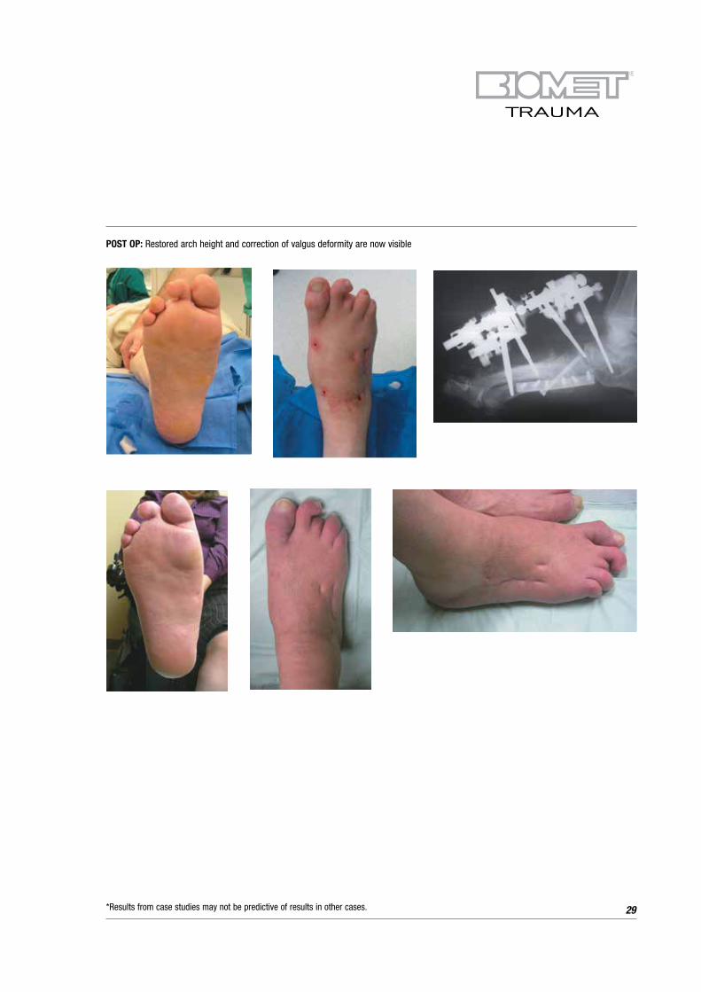
POST OP: Restored arch height and correction of valgus deformity are now visible
*Results from case studies may not be predictive of results in other cases.

Case Examples - Multi-planar Femoral Deformity
30
Figure #1: Left Proximal Femoral Focal Deficiency(PFFD) with short femur, mid-diaphyseal varus deformity, and distal femoral valgus deformity
Figure #2: PFFD, lateral x-ray, procurvatum deformity
Figure #3: PFFD, AP x-ray, XS MAC CORA perpendicular application for simultaneous correction of length and angulation
Figure #4: Clinical view, front
Figure #5: Clinical view, lateral Figure #6: AP x-ray with XS MAC after correction
Figure #7: AP view, XS MAC after correction
*Results from case studies may not be predictive of results in other cases.

14 year old male with short tibia secondary to fibular
hemimelia. The fibula can be stabilized using two arcs
on the MAC to reach laterally, allowing screw insertion
into the proximal and distal fibula
Adult Blounts patient demonstrating the centering of the Rotating
Ring
Adult MAC - Distal Femoral Valgus Correction
Application Examples
31*Results from case studies may not be predictive of results in other cases.

Radial Club Hand ApplicationXS MAC - Supramalleolar Osteotomy Clubfoot Correction
Foot Arch Correction Superior Placement of XS MAC
Femur Application utilizing the Ring C/D Mechanism
Blounts Correction utilizingthe Adult MAC
Blounts Correction utilizing the XS MAC
Club Foot Correction Lateral Placement of XS MAC
XS MAC for Derotational Osteotomy
Application Examples (Continued)
32*Results from case studies may not be predictive of results in other cases.
33
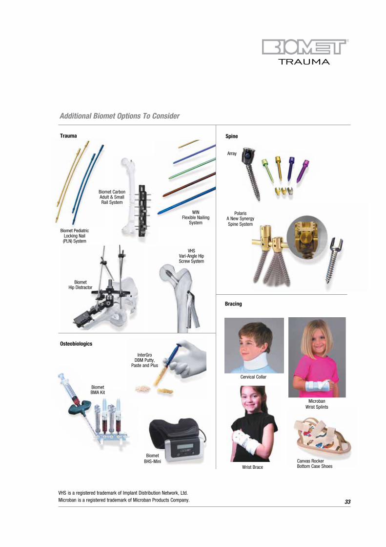
Biomet BMA Kit
Trauma Spine
Biomet Hip Distractor
WIN Flexible Nailing
System
Polaris
A New Synergy
Spine System
Bracing
Cervical Collar
Canvas Rocker Bottom Case Shoes
Microban Wrist Splints
Wrist Brace
Biomet Pediatric Locking Nail (PLN) System
VHS Vari-Angle Hip Screw System
Array
Osteobiologics
InterGro DBM Putty,
Paste and Plus
Biomet BHS-Mini
Additional Biomet Options To Consider
VHS is a registered trademark of Implant Distribution Network, Ltd. Microban is a registered trademark of Microban Products Company.
Biomet Carbon Adult & Small Rail System

Further Information
This brochure describes the surgical technique used by
Richard S. Davidson, M.D. Biomet Trauma, as the
manufacturer of this device, does not practice medicine and
does not recommend this product or any specific surgical
technique for use on any individual patient. The surgeon who
performs any implant procedure is responsible for
determining the appropriate product(s) and utilizing the
appropriate technique(s) for said implantation in each
individual patient
34
For further information, please contact the Customer
Service Department at:
Biomet Trauma
56 East Bell Drive
P.O. Box 587
Warsaw, IN 46581-0587 USA
+1 (574) 267 6639
www.Biomet.com

35
Notes:

36
Notes:


©2013 Biomet Orthopedics • Form No. BMET0331.0-ENG • REV011513
Responsible ManufacturerBiomet, Inc.P.O. Box 58756 E. Bell DriveWarsaw, Indiana 46581-0587USA
www.biomet.com
European RepresentativeBiomet UK, Ltd.Waterton Industrial EstateBridgend, South WalesCF31 3XAUK
www.biometeurope.com
Rx only.
0086
This publication and all content, artwork, photographs, names, logos and marks contained in it are protected by copyright, trademarks and other intellectual property rights owned by or licensed to Biomet or its affiliates. This publication must not be used, copied or reproduced in whole or in part for any purposes other than marketing by Biomet or its authorised representatives. Use for any other purposes is prohibited.
This material is intended for the sole use and benefit of the Biomet sales force and health care professionals. Biomet does not practice medicine and does not recommend any particular orthopaedic implant or surgical technique and is not responsible for use on a specific patient. The surgeon who performs any implant procedure is responsible for determining and utilising the appropriate techniques for implanting prosthesis in each individual patient.
For product information, including indications, contraindications, warnings, precautions and potential adverse effects, see the package insert and Biomet’s website.